computer networks - technical university of denmark · autumn 2008 computer networks ©robin sharp...
TRANSCRIPT

Robin SharpInformatics and Mathematical Modelling
Technical University of DenmarkPhone: (+45) 4525 3749
e-mail: [email protected]
Computer Networks

Autumn 2008 Computer Networks ©Robin Sharp 2
Basic Network Concepts
A computer network is a set of nodes connected by communication links.Nodes may be:
End systems, on which applications can runCommunication nodes, which just pass data

Autumn 2008 Computer Networks ©Robin Sharp 3
Types of Computer Network
Computer networks are often classified into:Local Area Networks (LAN): Size up to a few kilometers, typically covering a building, company or institution.Wide Area Networks (WAN): Large geographical coverage, perhaps world-wide.Metropolitan Area Networks (MAN): Covering a town or other relatively large area.
Classification is partly:Historical: Before liberalisation of telecommunication services, only tele-monopolies could set up large networks.Technological: Small networks can use cheaper technology to give high-speed access.

Autumn 2008 Computer Networks ©Robin Sharp 4
Concepts of Layering
Layer N offers a service (a set of facilities) to its “users” in the layer above, layer (N+1).
The service offered by layer N builds on the facilities offered by the layer below, layer (N-1).
Added value offered by layer N is achieved by exchange of messages following a set of rules characteristic for that layer: the (N)-protocol. Example:
Layer (N-1) offers an insecure service where data may be overheard by intruders.(N)-protocol specifies that messages sent via the (N-1)-service must be encrypted using secret key encryption.Layer N offers a secure, confidential service.

Autumn 2008 Computer Networks ©Robin Sharp 5
(N+1)-Layer
(N)-Layer
(N-1)-Layer
Layered Architectures (2)
Exchange controlledby (N)-protocol
(N+1)-entity
(N+1)-entity
(N)-layer offers(N)-service
System A System B
(N)-entity
(N)-entity
(N)-layer uses(N-1)-service

Autumn 2008 Computer Networks ©Robin Sharp 6
OSI Reference Model
Physical
Direct support to application processes(File transfer, e-mail, transactions,…)
End-to-end transfer of data(End-to-end error, sequence & flow control)Transfer of data between arbitrary systems(Routing, multiple subnets, flow control)
Transfer of data between directly connected systems (Error, sequence & flow control)Signalling on physical medium
Data Link
Network
Transport
Session
Presentation
Application
Organisation of dialogues(Synchronisation points, token control)
Transformation to suitable syntactic form(Character sets, data structures,…)
MEDIUM (cable, fibre, wireless,…)

Autumn 2008 Computer Networks ©Robin Sharp 7
OSI Lower Layers
Data Link: transfers data between directly connected systems (via direct cable or shared medium)Network: permits data transfer to arbitrary systems (“nodes”).Transport: provides illusion of direct end-to-end connection between processes in arbitrary systems.

Autumn 2008 Computer Networks ©Robin Sharp 8
Internet Layered Architecture
A simplified model, with OSI Upper Layers reduced to a single layer:
Application
Transport
Network
Data Link
Physical
Direct support to application processes
End-to-end transfer of data
Transfer of data between arbitrary systems
Transfer of data between directly connected systems
Signalling on physical medium

Autumn 2008 Computer Networks ©Robin Sharp 9
Services and Protocols
Autumn 2008 Computer Networks ©Robin Sharp 10
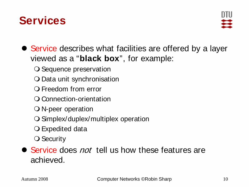
Services
Service describes what facilities are offered by a layer viewed as a “black box”, for example:
Sequence preservationData unit synchronisationFreedom from errorConnection-orientationN-peer operationSimplex/duplex/multiplex operationExpedited dataSecurity
Service does not tell us how these features are achieved.

Autumn 2008 Computer Networks ©Robin Sharp 11
Are the “data units” received by the receiver(s) the same size as those sent by the sender?
Message(/block-) oriented services:
Stream-oriented services:
Data unit synchronisation
Service
ServiceClip
anywhere

Autumn 2008 Computer Networks ©Robin Sharp 12
Errors in communication
Three basic error types:Message loss: Receiver fails to receive a message sent by the sender.Message corruption: Receiver receives a message different from the one sent by the sender.Spurious message: Receiver receives a message not sent by the (apparent) sender.
Measures of error rate:Bit Error Rate (BER): Fraction of received bits in error.Residual Error Rate (RER): Fraction of erroneous blocks.
us
ucl
NNNNNRER
+++=
Ns = Blocks sentNc = Corrupt blocksNl = Lost blocksNu = Spurious blocks
Autumn 2008 Computer Networks ©Robin Sharp 13
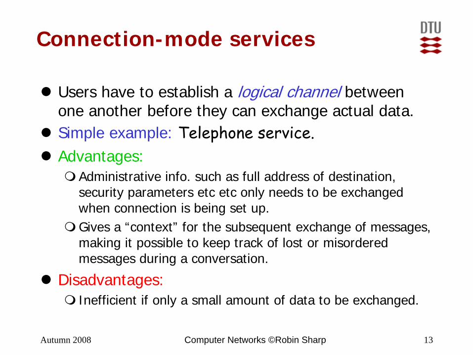
Connection-mode services
Users have to establish a logical channel between one another before they can exchange actual data.Simple example: Telephone service.Advantages:
Administrative info. such as full address of destination, security parameters etc etc only needs to be exchanged when connection is being set up.Gives a “context” for the subsequent exchange of messages, making it possible to keep track of lost or misorderedmessages during a conversation.
Disadvantages:Inefficient if only a small amount of data to be exchanged.

Autumn 2008 Computer Networks ©Robin Sharp 14
Connectionless-mode services
No connection set up before exchange of data.Each message is sent independently of the others.Simple example: Postal service.Advantages:
Less administration if small amount of data.May be faster: No need to wait for delivery of predecessors.
Disadvantages:All administrative info. has to be carried round in all messages, as the service has no memory of previous messages (stateless service).No guarantee of delivery in right order.No guarantee of delivery at all (“send-and-pray”).

Autumn 2008 Computer Networks ©Robin Sharp 15
N-peer operation
Point-to-point service:Offers point-to-point communication between two parties.Simple case: Two parties with equal status (Two-peer service).
Multi-peer service:Several users can communicate with one another at one time.Often classified into:
Broadcast service: All available users of service receive a message sent by one of them.Multicast service: A selected subset of users receive a message sent by one of them.Inverse broadcast: A single receiver can receive simultaneously from all the other service users.

Autumn 2008 Computer Networks ©Robin Sharp 16
N-plex services
Simplex service: Transfers messages in one direction only through logical or physical channel.Duplex service: Messages can pass between two parties in both directions.
Half-duplex: Only one direction at a time.Full duplex: Both directions at once.
Multiplex service: Many users can use the logical or physical channel, via some sharing mechanism. E.g.:
Frequency-division multiplexing: Use different frequencies (radio, TV, optical,…)Time-division multiplexing: Share the available time between the users.

Autumn 2008 Computer Networks ©Robin Sharp 17
Security
Typical aims of a secure service are to ensure:Confidentiality: Protection of information in transit from being picked up by unauthorised parties.Integrity: Protection of information in transit from being modified by alteration, deletion, replaying orinsertion of new messages.Authentication: Correct identification of the originof a message or electronic document.Non-repudiation: Protection against the sender orreceiver denying that a message was transferredbetween them.Availability: Protection against service being deniedto authorised users.

Autumn 2008 Computer Networks ©Robin Sharp 18
Quality of Service (QoS)
Summarises quantitative properties of a service:Throughput (bits/unit time)Delay (for connection setup, transfer, connection release)Reliability (in connection setup, transfer, connection release)Resilience (probability of unrequested disconnection)Error rate (BER, RER)Protection against intruders (passive, active,…)Priority (in delivery, in maintaining service quality)
Parameters often given in terms of:Target value (mean or median).Permissible spread (max/min interval, variance,…).(Possibly) a list of acceptable discrete values.

Autumn 2008 Computer Networks ©Robin Sharp 19
Protocols
Specify rules for how to provide the desired service:Rules of procedure: Which messages to exchange in response to events occurring at the interface to the layer or internally (e.g. timeout).Message formats: Format and encoding of messages to be transferred between the parties involved.
OSI notation:Service Data Unit (SDU): A message supplied by a user of a service.Protocol Data Unit (PDU): A message exchanged between two or more parties as part of a protocol.An initial is often used to indicate the relevant OSI layer. E.g. NPDU: A PDU exchanged in the Network layer.

Autumn 2008 Computer Networks ©Robin Sharp 20
Protocol Control Information (PCI)
Information used to control the exchange of PDUsaccording to the rules of the protocol, such as:
Identification of source and destination of PDU.Sequence numbers used to detect lost or misordered PDUs.Checksums used to detect corrupted PDUs.Timestamps used to detect outdated PDUs.Security-related information.
An administrative PDU (e.g. acknowledgement for receipt of data) may consist just of PCI.In a Data PDU, PCI is added as a header and/or trailer to (part of) an SDU supplied by the user.

Autumn 2008 Computer Networks ©Robin Sharp 21
PCI in a PDU
Simple example: PCI in header, data from whole SDU.
(N)-SDU
(N)-PCI
(N)-PCI (N)-SDU
(N)-PDU
(N)-SAP
(N+1)-Layer
(N)-Layer
Transmissionvia (N)-Protocol

Autumn 2008 Computer Networks ©Robin Sharp 22
Embedding of layered PDUs
In a layered architecture, PCI will be added in each layer. Simple case:
Application data
APDU
TPDU
NPDU
DPDU
User
A
T
N
D
Layer

Autumn 2008 Computer Networks ©Robin Sharp 23
Segmented embedded PDUs
When PDUs get larger than a given layer permits, segmentation may be needed, giving many fragments:
Effective data rate may drop due to sudden jumps inamount of PCI.

Autumn 2008 Computer Networks ©Robin Sharp 24
Network Technology

Autumn 2008 Computer Networks ©Robin Sharp 25
Communication nodes
Communication nodes typically implement OSI layers up to and including the Network layer:
Comm. nodes are responsible for accepting PDUs on incoming link, routing to an outgoing link and transmitting on outgoing link.

Autumn 2008 Computer Networks ©Robin Sharp 26
Routers
Implement layers up to (at least) Network layer.Can choose a suitable route for sending an incoming PDU on to its destination.May be able to filter off irrelevant or unsuitable traffic, for example:
Traffic which has taken too long time to cross the network.Traffic from known unreliable sources.Traffic on incoming links not “matching” the claimed source address.Traffic to destinations or applications which do not want it.Traffic which misuses the protocols in some way.

Autumn 2008 Computer Networks ©Robin Sharp 27
Implement layers up to Data Link layer.Are used to connect segments within a given network.
Bridges
DPh Ph
MEDIUMSegment 2
MEDIUMSegment 1
Typical functions:Adaptation between different conventions used for signalling inPhysical layer in different segments.Filtering to remove traffic which does not need to cross the bridge to reach destination. (Note: not really routing!)

Autumn 2008 Computer Networks ©Robin Sharp 28
LAN Technologies
Differ from WAN technologies especially in the Data Link and Physical layers.Data Link layer divided into two sub-layers:
Technology-dependent Medium Access Control sub-layer.Technology-independent Logical Link Control sub-layer, which can be based on various different MAC sub-layers.
LLC
MAC
Physical
MEDIUM
14243
Data Link layer

Autumn 2008 Computer Networks ©Robin Sharp 29
IEEE/ISO LAN MAC Standards
IEEE ISO Technology
802.3 8802-3 CSMA/CD (“Ethernet”)802.4 8802-4 Token Bus802.5 8802-5 Token Ring802.6 8802-6 Distributed Queue Dual Bus (DQDB)802.9 8802-9 Integrated Services (IS) LAN802.11 8802-11 Wireless LAN802.12 8802-12 Demand-priority Access802.15 8802-15 Wireless Personal Area Networks (WPAN)802.16 8802-16 Fixed Broadband Wireless Access (FBWA)
80

Autumn 2008 Computer Networks ©Robin Sharp 30
Contention protocols
Simple principle for controlling access to medium: Senders compete for access. If medium is free, transmission is OK.Typically used on broadcast media (bus, cable, wireless).Basic feature of broadcast medium: Signals spread out from sender in all directions.
If several systems send at same time, signals “collide” and messages gets lost.

Autumn 2008 Computer Networks ©Robin Sharp 31
CSMA/CD
Unrestricted contention, where systems just try to send when they want to, is inefficient: Many collisions (⇒ many retransmissions) occur as traffic intensity rises.CSMA/CD uses two rules to increase efficiency:
Carrier Sense Multiple Access: Listen before sending. If medium is occupied, wait a random time before trying again.Collision Detect: Listen while sending. If another system is sending at same time, stop transmitting and try again later.
In IEEE/ISO standardised CSMA/CD, the random waiting time is doubled (on average…) on each retry (Binary Exponential Backoff). This ensures stability as traffic intensity rises.

Autumn 2008 Computer Networks ©Robin Sharp 32
CSMA/CD (2)
Operation of CSMA/CD when collision occurs:
Collision occurs if several senders find medium free at same time.After detection of collision, all systems are informed (CE), and the senders wait a random time before trying again.

Autumn 2008 Computer Networks ©Robin Sharp 33
CSMA/CD (3)
For collisions to be detected, transmission of a PDU must last (significantly) longer than the time required for signals to reach the most distant systems. So:
Min. PDU length (depending on data rate)Max. physical extent of medium
CSMA/CD standards cover several technologies, media and data rates. Important examples:
10 Mbit/s thick coaxial cable (classic Ethernet).10 Mbit/s thin coaxial cable (thinwire Ethernet).10 Mbit/s unshielded twisted pair, UTP-5.100 Mbit/s unshielded twisted pair, UTP-5 (fast Ethernet).1000 Mbit/s coaxial cable (gigabit Ethernet).

Autumn 2008 Computer Networks ©Robin Sharp 34
Switched Ethernet
An alternative to cable-based Ethernet, in which path between sender and receiver is set up dynamically in a switch:
If path can be set up, full bandwidth of medium is available between the two nodes.
Contention only for simultaneous transmissions to same destination.

Autumn 2008 Computer Networks ©Robin Sharp 35
Wireless LAN
Important new technology, allowing mobility.Three basic setups:
(a) Basic: single Access Point (AP)(b) Extended: multiple APs(c) Ad hoc (peer-to-peer): no AP

Autumn 2008 Computer Networks ©Robin Sharp 36
Wireless LAN (2)
A large number of standardised technologies, all part of IEEE 802.11 standard:
Standard Physical Layer Technology802.11 2.4 GHz radio band, 1 or 2Mbit/s data rate802.11a 5 GHz radio band, up to 54 Mbit/s802.11b 2.4 GHz radio band, 1, 2, 5.5 or 11 Mbit/s802.11g 2.4 GHz radio band, 22 or 54 Mbit/s802.11h Spectrum management to use 5GHz band
in Europe.
802.11e describes enhancements to give QoS.
802.11i describes enhancements to give improved security.

Autumn 2008 Computer Networks ©Robin Sharp 37
CSMA/CA Wireless MAC ProtocolA contention protocol based on CSMA together with:
Collision Avoidance via reservation slots.ACKnowledgments to check that contention really didn’t occur.

Course 02152, DTU, Autumn 2008
Thank you for
your attention
8