computer networks unit i - vidyarthiplus
TRANSCRIPT
CS2302-COMPUTER NETWORKS
III YEAR
COMPUTER NETWORKS UNIT I
Network architecture – layers – Physical links – Channel Access on links – Hybrid multiple access techniques – Issues in the data link layer – Framing – Error correction and detection – Link-level flow control Introduction Computer Network: Definition Collection of autonomous computers interconnected by single
technology.
Connectivity Connectivity occurs between two computers through physical medium
like coaxial cable or an optical fiber.
Physical Medium – Link
Computers - Nodes
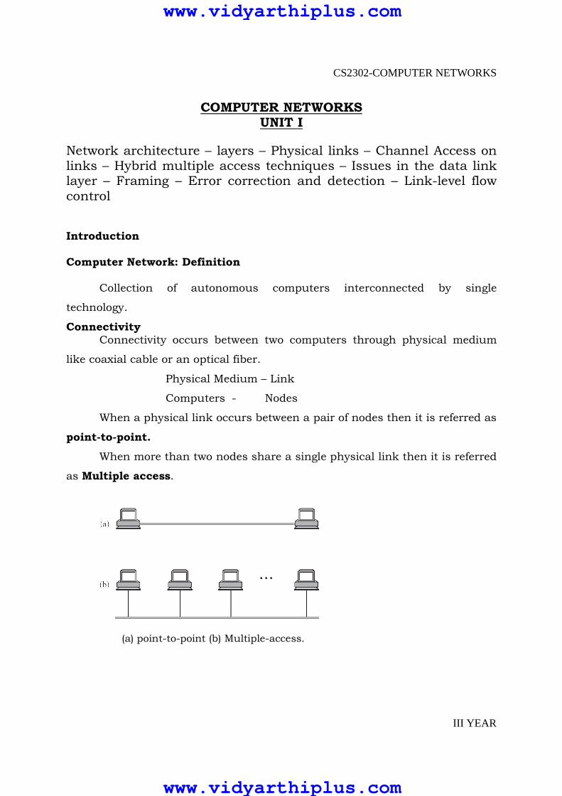
When a physical link occurs between a pair of nodes then it is referred as
point-to-point.
When more than two nodes share a single physical link then it is referred
as Multiple access.
(a) point-to-point (b) Multiple-access.
www.vidyarthiplus.com
www.vidyarthiplus.com

CS2302-COMPUTER NETWORKS
III YEAR
Data communication between the nodes is done by forwarding the data
from one link to another. The systematic way of organizing these forwarding
nodes form a switched network.
Two common types of switched network are
� Circuit switched – e.g. Telephone System
� Packet switched – e.g. Postal System
Packet Switched Network
In this network nodes send discrete blocks of data to each other. These
blocks can be called as packet or message.
Store and forward strategy:
This network follows this technique. It means “Each node receives a
complete packets over the link, stores in internal memory and then forwards to
next node”.
Circuit Switched Network It first establishes a circuit across the links and allows source node to
send stream of bits across this circuit to the destination node
The representation of network is given by cloud symbol
Fig: Switched network.
Cloud represents the network
Nodes inside the cloud (Switches) – Implement the network
Nodes outside the cloud (host) - Use the network
www.vidyarthiplus.com
www.vidyarthiplus.com
CS2302-COMPUTER NETWORKS
III YEAR
Internetwork
Set of independent network are interconnected to form inter network or
internet. Node that is connected to two or more network is called router or
gateway. It is responsible for forwarding data between the networks.
Addressing
The final requirement is that each node must be able to say which of the
other node it wants to communicate with.
This is done by assigning address to each node. when a source node
wants to deliver message to destination node, it specifies the address of
destination node.
Switches and Routers use this address to decide how to forward the
message. This process based on address is called Routing.
Unicast – sending message to single node.
Broadcast – Sending message to all the nodes on the network.
Multicast – Sending message to some subnet not to all.
Resource Sharing
Pblm: How do several hosts share the same link when they all want to
use it at the same time?
Sol: Multiplexing – System resources are shared among multiple users
Methods:
1. Synchronous Time Division Multiplexing(STDM)
Divide time into equal sized quanta
2. Frequency Division Multiplexing(FDM)
Transmit each flow at different frequency
3. Statistical Multiplexing
First two methods are limited in 2 ways
� If one flow does not have data to send then its time quantum
remains idle, even the other flow has data to transmit.
� No of flows are fixed and known ahead of time, it cannot be
resized.
www.vidyarthiplus.com
www.vidyarthiplus.com

CS2302-COMPUTER NETWORKS
III YEAR
Statistical methods combine the ideas of both STDM and FDM
� Data from each flow is transmitted on demand so no idle
quantum
� It defines upper bound on size of data and it is referred as
packet.
Common communication patterns
Communication between a pair of processes is done by request /
reply basis. The process which sends request is referred as client and the one
which honors the request is referred as server.
This can be done using channels. Two types of channels are
� Request / Reply channels
� Message stream Channels
Reliability
To get the reliable network, it is necessary to find how network fails.
Three classes of failures
� Bit error
� Packet loss
� Physical link and node failure
Network Architecture
Networks do not remain fixed at single point in time, but it must evolve
to accommodate changes based on the technologies on which they are based
and demands made by application programmer.
Network architecture guides the design and implementation of network.
Two commonly used architecture are
� OSI Architecture
� Internet or TCP/IP architecture
Layering and Protocols
When the system gets complex, the system designer introduces another
level of abstraction. It defines unifying model with important aspects of the
system, encapsulated this model in interface objects and hide it from users
www.vidyarthiplus.com
www.vidyarthiplus.com

CS2302-COMPUTER NETWORKS
III YEAR
In network, abstraction leads to layering. Layering provides two nice
features.
� It decomposes the problem of building a network into more
manageable components. Rather than implementing a monolithic
piece of software that does everything implement several layers, each
of which solves one part of the problem.
� It provides more modular design. To add some new service, it is
enough to modify the functionality at one layer, reusing the functions
provided at all the other layers.
Protocols A protocol is a set of rules that governs data communication. It defines
what is communicated, how it is communicated, and when it is communicated.
The key elements of a protocol are syntax, semantics and timing.
Each protocol defines two different interfaces.
� Service interface - to the other objects on the same computer
that want to use its communication services. This service interface
defines the operations that local objects can perform on the
protocol.
� Peer interface - to its counterpart (peer) on another machine. It
also defines the form and meaning of messages exchanged
between protocol peers to implement the communication service.
Fig: Service and peer interfaces.
www.vidyarthiplus.com
www.vidyarthiplus.com
CS2302-COMPUTER NETWORKS
III YEAR
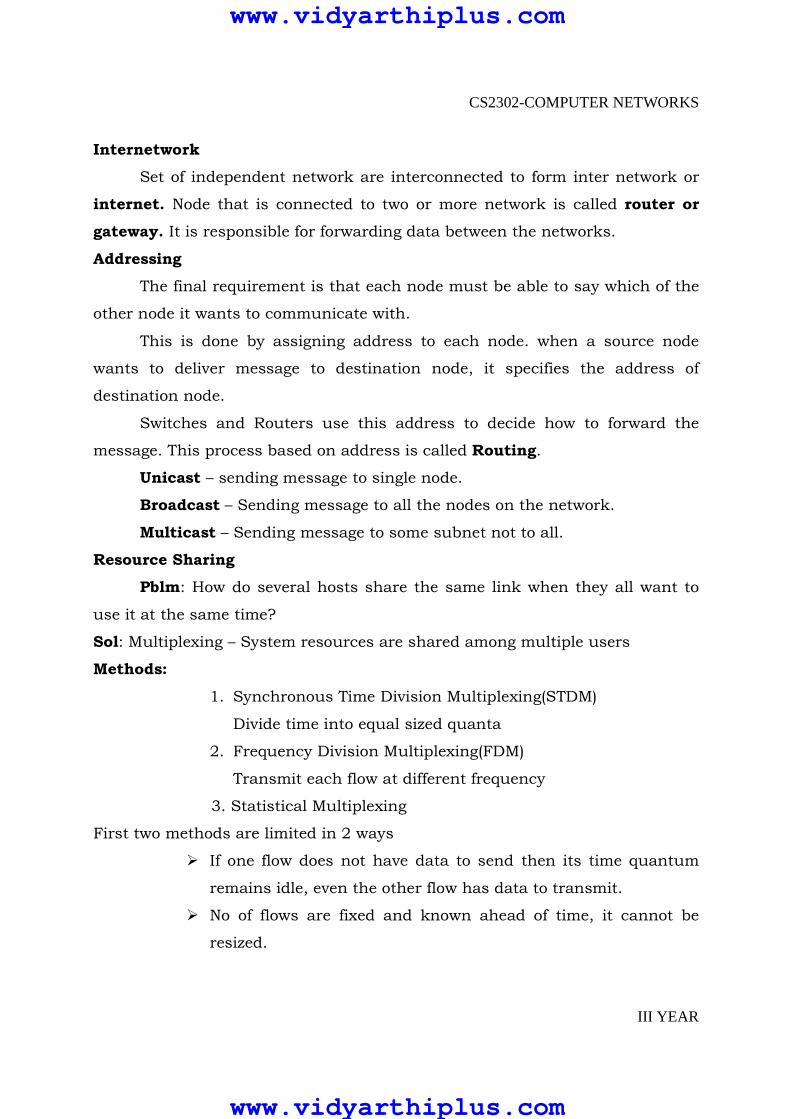
Except at the hardware level, peer to peer communication is indirect.
We can represent these protocols as protocol graph. Nodes of the graph
correspond to protocols, and the edges represent a depends-on relation.
Fig: Example of a protocol graph.
For example, the file access program on host 1 wants to send a message
to its peer on host 2 using the communication service offered by protocol RRP.
In this case, the file application asks RRP to send the message on its behalf. To
communicate with its peer, RRP then invokes the services of HHP, which in
turn transmits the message to its peer on the other machine. Once the
message has arrived at protocol HHP on host 2, HHP passes the message up to
RRP, which in turn delivers the message to the file application. In this
particular case, the application is said to employ the services of the protocol
stack RRP/HHP.
www.vidyarthiplus.com
www.vidyarthiplus.com
CS2302-COMPUTER NETWORKS
III YEAR
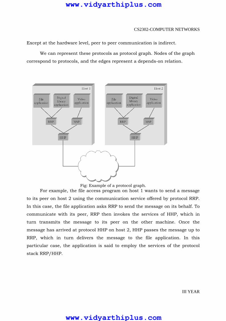
Encapsulation Control information must be added with the data to instruct the peer
how to handle with the received message. It will be added into the header or
trailer.
Header - Small data structure from few bytes to few kilobytes attached to
the front of message.
Trailer – Information will be added at the end of the message
Payload or message body – Data send by the program
In this case data is encapsulated with new message created by
protocol at each level.
Fig: High-level messages are encapsulated inside of low-level messages.
In this example HHP encapsulates RRP’s message by attaching a header
of its own. Then HHP sends the message to its peer over some network, and
then when the message arrives at the destination host, it is processed in the
opposite order.
www.vidyarthiplus.com
www.vidyarthiplus.com

CS2302-COMPUTER NETWORKS
III YEAR
Multiplexing and De-Multiplexing
The fundamental idea of packet switching is to multiplex multiple flows
of data over a single physical link. This can be achieved by adding identifier to
the header message. It is known as demultiplexing or demux key. It gives the
address to which it has to communicate.
The messages are demultiplexed at the destination side. In some cases
same demux key is used on both sides and in some cases different keys are
used.
OSI Architecture
ISO defines a common way to connect computer by the architecture
called Open System Interconnection(OSI) architecture.
Network functionality is divided into seven layers.
www.vidyarthiplus.com
www.vidyarthiplus.com

CS2302-COMPUTER NETWORKS
III YEAR
Organization of the layers The 7 layers can be grouped into 3 subgroups
1. Network Support Layers
Layers 1,2,3 - Physical, Data link and Network are the network
support layers. They deal with the physical aspects of moving data from
one device to another such as electrical specifications, physical
addressing, transport timing and reliability.
2. Transport Layer Layer4, transport layer, ensures end-to-end reliable data
transmission on a single link.
3. User Support Layers Layers 5,6,7 – Session, presentation and application are the user
support layers. They allow interoperability among unrelated software
systems
An Data exchange using the OSI model
www.vidyarthiplus.com
www.vidyarthiplus.com
CS2302-COMPUTER NETWORKS
III YEAR
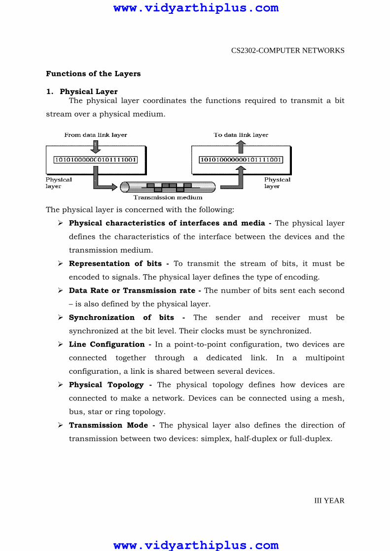
Functions of the Layers 1. Physical Layer
The physical layer coordinates the functions required to transmit a bit
stream over a physical medium.
The physical layer is concerned with the following:
� Physical characteristics of interfaces and media - The physical layer
defines the characteristics of the interface between the devices and the
transmission medium.
� Representation of bits - To transmit the stream of bits, it must be
encoded to signals. The physical layer defines the type of encoding.
� Data Rate or Transmission rate - The number of bits sent each second
– is also defined by the physical layer.
� Synchronization of bits - The sender and receiver must be
synchronized at the bit level. Their clocks must be synchronized.
� Line Configuration - In a point-to-point configuration, two devices are
connected together through a dedicated link. In a multipoint
configuration, a link is shared between several devices.
� Physical Topology - The physical topology defines how devices are
connected to make a network. Devices can be connected using a mesh,
bus, star or ring topology.
� Transmission Mode - The physical layer also defines the direction of
transmission between two devices: simplex, half-duplex or full-duplex.
www.vidyarthiplus.com
www.vidyarthiplus.com

CS2302-COMPUTER NETWORKS
III YEAR
2. Data Link Layer It is responsible for transmitting frames from one node to next node.
The other responsibilities of this layer are
� Framing - Divides the stream of bits received into data units called
frames.
� Physical addressing – If frames are to be distributed to different systems
on the n/w , data link layer adds a header to the frame to define the
sender and receiver.
� Flow control- If the rate at which the data are absorbed by the receiver
is less than the rate produced in the sender ,the Data link layer imposes
a flow ctrl mechanism.
� Error control- Used for detecting and retransmitting damaged or lost
frames and to prevent duplication of frames. This is achieved through a
trailer added at the end of the frame.
� Access control -Used to determine which device has control over the
link at any given time.
3. NETWORK LAYER
This layer is responsible for the delivery of packets from source to destination.
www.vidyarthiplus.com
www.vidyarthiplus.com

CS2302-COMPUTER NETWORKS
III YEAR
It is mainly required, when it is necessary to send information from one
network to another.
The other responsibilities of this layer are � Logical addressing - If a packet passes the n/w boundary, we need
another addressing system for source and destination called logical
address.
� Routing – The devices which connects various networks called routers
are responsible for delivering packets to final destination.
4. TRANSPORT LAYER � It is responsible for Process to Process delivery.
� It also ensures whether the message arrives in order or not.
The other responsibilities of this layer are � Port addressing - The header in this must therefore include a address
called port address. This layer gets the entire message to the correct
process on that computer.
� Segmentation and reassembly - The message is divided into segments
and each segment is assigned a sequence number. These numbers are
arranged correctly on the arrival side by this layer.
� Connection control - This can either be connectionless or
connection-oriented. The connectionless treats each segment as a
individual packet and delivers to the destination. The connection-
www.vidyarthiplus.com
www.vidyarthiplus.com

CS2302-COMPUTER NETWORKS
III YEAR
oriented makes connection on the destination side before the delivery.
After the delivery the termination will be terminated.
� Flow and error control - Similar to data link layer, but process to
process take place.
5.SESSION LAYER
This layer establishes, manages and terminates connections between
applications.
The other responsibilities of this layer are
� Dialog control - This session allows two systems to enter into a dialog
either in half duplex or full duplex.
� Synchronization-This allows to add checkpoints into a stream of data.
6.PRESENTATION LAYER
It is concerned with the syntax and semantics of information
exchanged between two systems.
www.vidyarthiplus.com
www.vidyarthiplus.com
CS2302-COMPUTER NETWORKS
III YEAR
The other responsibilities of this layer are
� Translation – Different computers use different encoding system, this
layer is responsible for interoperability between these different encoding
methods. It will change the message into some common format.
� Encryption and decryption-It means that sender transforms the
original information to another form and sends the resulting message
over the n/w. and vice versa.
� Compression and expansion-Compression reduces the number of bits
contained in the information particularly in text, audio and video.
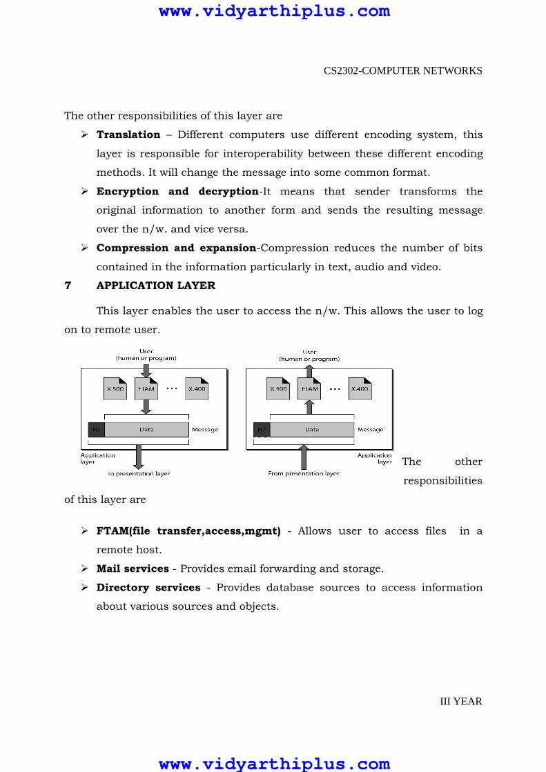
7 APPLICATION LAYER
This layer enables the user to access the n/w. This allows the user to log
on to remote user.
The other
responsibilities
of this layer are
� FTAM(file transfer,access,mgmt) - Allows user to access files in a
remote host.
� Mail services - Provides email forwarding and storage.
� Directory services - Provides database sources to access information
about various sources and objects.
www.vidyarthiplus.com
www.vidyarthiplus.com

CS2302-COMPUTER NETWORKS
III YEAR
The interaction between layers in the OSI model
www.vidyarthiplus.com
www.vidyarthiplus.com
CS2302-COMPUTER NETWORKS
III YEAR
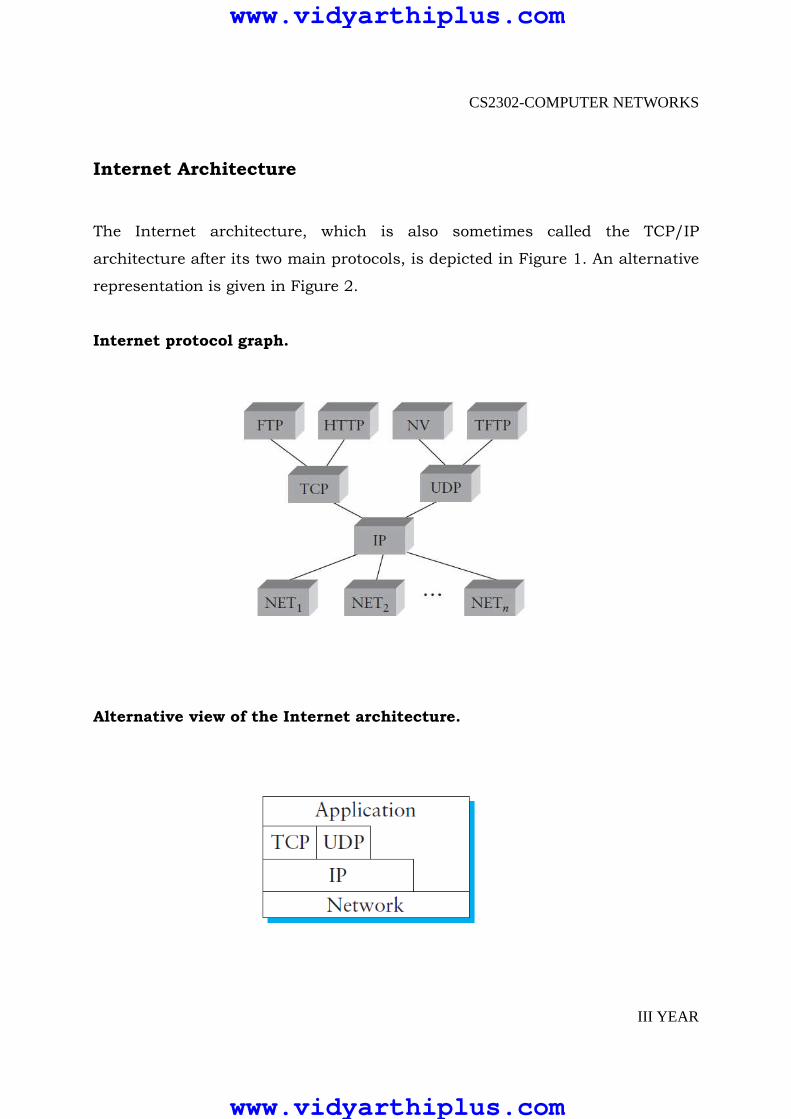
Internet Architecture
The Internet architecture, which is also sometimes called the TCP/IP
architecture after its two main protocols, is depicted in Figure 1. An alternative
representation is given in Figure 2.
Internet protocol graph.
Alternative view of the Internet architecture.
www.vidyarthiplus.com
www.vidyarthiplus.com

CS2302-COMPUTER NETWORKS
III YEAR
� The Internet architecture evolved out of experiences with an earlier
packet-switched network called the ARPANET.
� Both the Internet and the ARPANET were funded by the Advanced
Research Projects Agency (ARPA), one of the R&D funding agencies of the
U.S. Department of Defense.
Layers of Internet Architecture
� Internet Architecture uses a four-layer model is used At the lowest level
are a wide variety of network protocols, denoted NET1, NET2, and so on.
In practice, these protocols are implemented by a combination of
hardware (e.g., a network adaptor) and software(e.g., a network device
driver).
� For example, you might find Ethernet or Fiber Distributed Data Interface
(FDDI) protocols at this layer.
� The second layer consists of a single protocol—the Internet Protocol (IP).
This is the protocol that supports the interconnection of multiple
networking technologies into a single, logical internetwork.
� The third layer contains two main protocols—the Transmission Control
Protocol (TCP) and the User Datagram Protocol (UDP).
• TCP provides a reliable byte-stream channel, and UDP
provides an unreliable datagram delivery channel.
• In the language of the Internet, TCP and UDP are sometimes
called end-to-end protocols, although it is equally correct to
refer to them as transport protocols.
� Running above the transport layer are a range of application protocols,
such as FTP, TFTP (Trivial File Transport Protocol), Telnet (remote login),
and SMTP (Simple Mail Transfer Protocol, or electronic mail), that enable
the interoperation of popular applications.
www.vidyarthiplus.com
www.vidyarthiplus.com

CS2302-COMPUTER NETWORKS
III YEAR
Features of Internet
� The Internet architecture does not imply strict layering.
� Second, internet architecture uses hourglass shape—it is wide at the top
narrow in the middle, and wide at the bottom. This shape actually
reflects the central philosophy of the architecture. That is, IP serves as
the focal point for the architecture—it defines a common method for
exchanging packets among a wide collection of networks.
� A final attribute of the Internet architecture is that in order for someone
to propose a new protocol to be included in the architecture, they must
produce both a protocol specification and at least one (and preferably
two) representative implementations of the specification.
PHYSICAL LINKS
1.Network links are implemented on a variety of different physical media,
including
a. Twisted pair (the wire that your phone connects to),
b. Coaxial cable (the wire that your TV connects to),
c. Optical fiber (the medium most commonly used for high-
bandwidth, long distance links),
d. space (the stuff that radio waves, microwaves, and infrared beams
propagate through)
2. Whatever the physical medium, it is used to propagate signals.
3. These signals are actually electromagnetic waves traveling at the speed of
light.
4. One important property of an electromagnetic wave is the frequency,
measured in hertz, with which the wave oscillates.
www.vidyarthiplus.com
www.vidyarthiplus.com
CS2302-COMPUTER NETWORKS
III YEAR
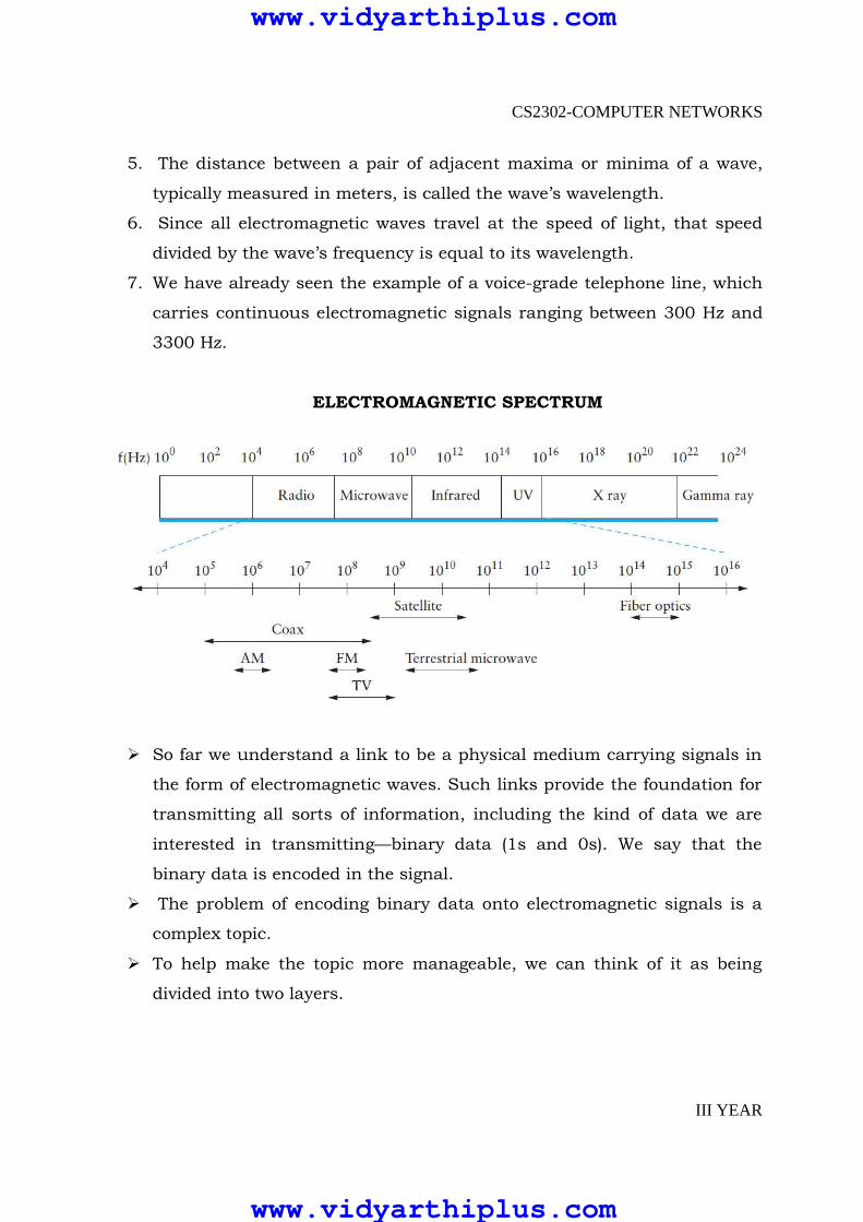
5. The distance between a pair of adjacent maxima or minima of a wave,
typically measured in meters, is called the wave’s wavelength.
6. Since all electromagnetic waves travel at the speed of light, that speed
divided by the wave’s frequency is equal to its wavelength.
7. We have already seen the example of a voice-grade telephone line, which
carries continuous electromagnetic signals ranging between 300 Hz and
3300 Hz.
ELECTROMAGNETIC SPECTRUM
� So far we understand a link to be a physical medium carrying signals in
the form of electromagnetic waves. Such links provide the foundation for
transmitting all sorts of information, including the kind of data we are
interested in transmitting—binary data (1s and 0s). We say that the
binary data is encoded in the signal.
� The problem of encoding binary data onto electromagnetic signals is a
complex topic.
� To help make the topic more manageable, we can think of it as being
divided into two layers.
www.vidyarthiplus.com
www.vidyarthiplus.com

CS2302-COMPUTER NETWORKS
III YEAR
� The Lower layer is concerned with modulation—varying the frequency,
amplitude, or phase of the signal to effect the transmission of
information.
CABLES
� If the nodes you want to connect are in the same room, in the same
building ,or even on the same site (e.g., a campus), then you can buy a
piece of cable and physically string it between the nodes. Exactly what
type of cable you choose to install depends on the technology you plan to
use to transmit data over the link;
Common types of cables and fibers available for local links.
Leased Lines
� If the two nodes you want to connect are on opposite sides of the
country, or even across town, then it is not practical to install the link
yourself.
� Your only option is to lease a dedicated link from the telephone company,
in which case all you’ll need to be able to do is conduct an intelligent
conversation with the phone company customer.
www.vidyarthiplus.com
www.vidyarthiplus.com

CS2302-COMPUTER NETWORKS
III YEAR
Common bandwidths available from the carriers
� DS1 and DS3 (they are also sometimes called T1 and T3,respectively) are
relatively old technologies that were orginally defined for copper based
transmission media. DS1 is equal to the aggregation of 24 digital voice
circuits of 64 Kbps each, and DS3 is equal to 28 DS1 links. All the STS-N
links are for optical fiber.
� (STS stands for Synchronous Transport Signal). STS-1 is the base link
speed, and each STS-N has N times the bandwidth of STS-1. An STS-N link
is also sometimes called an OC-N link (OC stands for optical carrier).
Last-Mile Links
� We call these “last-mile” links because they often span the last mile from
the home to a network service provider.
� This links typically connect a home to an existing network.
� This means they are probably not suitable for use in building a complete
network from scratch, but if you’ve already succeeded in building a
network—and “you” happen to be either the telephone company or the
cable company—then you can use these links to reach millions of
customers.
www.vidyarthiplus.com
www.vidyarthiplus.com
CS2302-COMPUTER NETWORKS
III YEAR
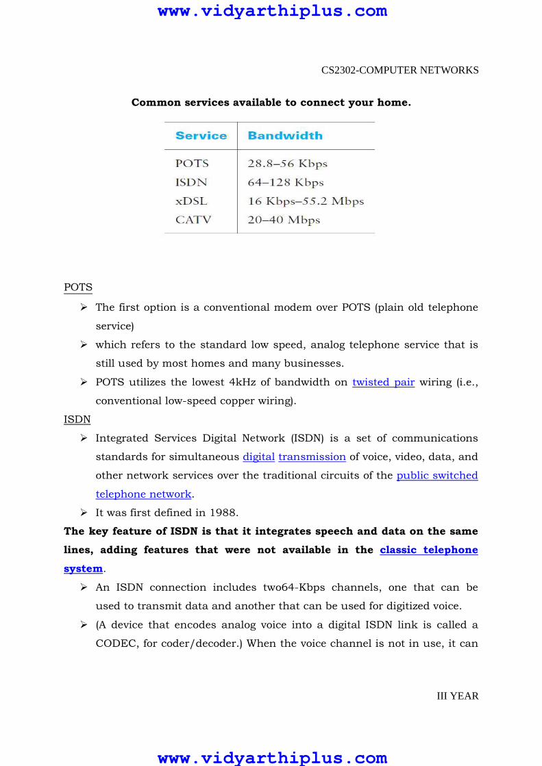
Common services available to connect your home.
POTS
� The first option is a conventional modem over POTS (plain old telephone
service)
� which refers to the standard low speed, analog telephone service that is
still used by most homes and many businesses.
� POTS utilizes the lowest 4kHz of bandwidth on twisted pair wiring (i.e.,
conventional low-speed copper wiring).
ISDN
� Integrated Services Digital Network (ISDN) is a set of communications
standards for simultaneous digital transmission of voice, video, data, and
other network services over the traditional circuits of the public switched
telephone network.
� It was first defined in 1988.
The key feature of ISDN is that it integrates speech and data on the same
lines, adding features that were not available in the classic telephone
system.
� An ISDN connection includes two64-Kbps channels, one that can be
used to transmit data and another that can be used for digitized voice.
� (A device that encodes analog voice into a digital ISDN link is called a
CODEC, for coder/decoder.) When the voice channel is not in use, it can
www.vidyarthiplus.com
www.vidyarthiplus.com
CS2302-COMPUTER NETWORKS
III YEAR
be combined with the data channel to support up to 128 Kbps of data
bandwidth.
� For many years ISDN was viewed as the future for modest bandwidth
into the home.
� ISDN has now been largely overtaken, however, by two newer
technologies: xDSL (digital subscriber line) and cable modems.
� The former is actually a collection of technologies that are able to
transmit data at high speeds over the standard twisted pair lines that
currently come into most homes in the United States(and many other
places).
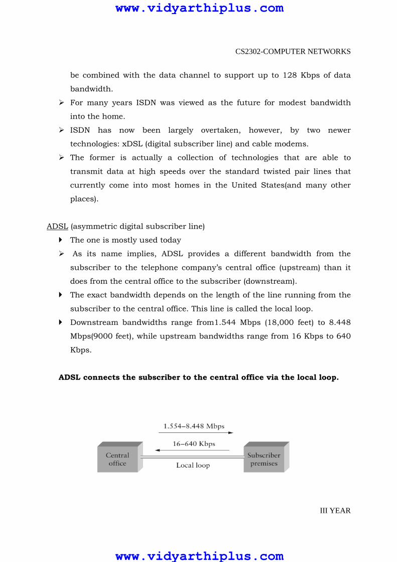
ADSL (asymmetric digital subscriber line)
� The one is mostly used today
� As its name implies, ADSL provides a different bandwidth from the
subscriber to the telephone company’s central office (upstream) than it
does from the central office to the subscriber (downstream).
� The exact bandwidth depends on the length of the line running from the
subscriber to the central office. This line is called the local loop.
� Downstream bandwidths range from1.544 Mbps (18,000 feet) to 8.448
Mbps(9000 feet), while upstream bandwidths range from 16 Kbps to 640
Kbps.
ADSL connects the subscriber to the central office via the local loop.
www.vidyarthiplus.com
www.vidyarthiplus.com

CS2302-COMPUTER NETWORKS
III YEAR
VDSL
� An alternative technology that has yet to be widely deployed—very high
data rate digital subscriber line (VDSL)—is symmetric, with data rates
ranging from 12.96 Mbps to 55.2 Mbps. VDSL runs over much shorter
distances—1000 to 4500 feet.
� Which means that it will not typically reach from the home to the central
office. Instead, the telephone company would have to put VDSL
transmission hardware in neighborhoods, with some other technology
(e.g., STS-N running over fiber) connecting the neighborhood to the central
officeThis is sometimes called “fiber to the neighborhood.
VDSL connects the subscriber to the optical network that reaches the
neighborhood
www.vidyarthiplus.com
www.vidyarthiplus.com

CS2302-COMPUTER NETWORKS
III YEAR
CATV
� Cable modems are an alternative to the various types of DSL. As the name
suggests, this technology uses the cableTV (CATV) infrastructure, which
currently reaches 95% of the households in the United States. (Only 65% of
U.S. homes actually subscribe.)
� In this approach, some subset of the available CATV channels are made
available for transmitting digital data, where a single CATV channel has a
bandwidth of 6 MHz.
� CATV, like ADSL, is used in an asymmetric way, with downstream rates
much greater than upstream rates.
� The technology is currently able to achieve 40 Mbps downstream on a
single CATV channel, with 100 Mbps as the theoretical capacity.
� The upstream rate is roughly half the downstream rate(i.e., 20 Mbps) due
to a 1000-fold decrease in the signal-to-noise ratio.
� It is also the case that fewer CATV channels are dedicated to upstream
traffic than to downstream traffic.
� Unlike DSL, the bandwidth is shared among all subscribers in a
neighborhood (a fact that led to some amusing advertising from DSL
providers).
WIRELESS LINKS
� Wireless Links The field of wireless communication is exploding, both
economically and technologically.
� The Advanced Mobile Phone System (AMPS) has been the standard for
cellular phones in the United States for several years. AMPS, which is
based on analog technology, is rapidly giving way to digital cellular–PCS
(Personal Communication Services)in the United States and Canada, and
GSM (Global System for Mobile Communication)in the rest of the world.
www.vidyarthiplus.com
www.vidyarthiplus.com
CS2302-COMPUTER NETWORKS
III YEAR
� All three systems currently use a system of towers to transmit signals,
although some significant efforts have been made to supplement this
infrastructure by ringing the globe with a grid of medium- and low-orbit
satellites. These projects—which include ICO, Globalstar, Iridium, and
Teledesic—have had mixed success.
� Those that are still viable are mostly focusing on delivery of telephone
service to those increasingly rare parts of the globe where cellular service
is not available.
� Thinking a bit less globally, frequency bands from the radio and infrared
portions of the electromagnetic spectrum can be used to provide wireless
links over short distances, such as inside office buildings, coffee shops,
building complexes, and campuses.
� In the case of infrared, signals with wavelengths in the 850–950-
nanometer range can be used to transmit data at1-Mbps rates over
distances of about 10 m.
� This technology does not require line of sight, but is limited to in-building
environments.
� In the case of radio, several different bands are currently being made
available for data communication. For example, bands at 5.2 GHz and 17
GHz are allocated to HIPERLAN (High Performance European Radio LAN)
in Europe.
� Similarly, bandwidth at 2.4 GHz has been set aside in many countries for
use with the IEEE 802.11standard for wireless LANs.
� (Additional bandwidth is available at 5 GHz, but unfortunately it is subject
to interference from microwave ovens.) IEEE 802.11, which is an evolving
standard that supports data rates of up to 54 Mbps.
� Another interesting development in the wireless arena is the Bluetooth
radio interface that operates in the 2.45-GHz frequency band. Bluetooth is
designed for short distances (on the order of 10 m) with a bandwidth of 1
Mbps.
www.vidyarthiplus.com
www.vidyarthiplus.com
CS2302-COMPUTER NETWORKS
III YEAR
� Its developers envision it being used in all devices (e.g., printers,
workstations, laptops, projectors, PDAs, mobile phones), thereby
eliminating the need for wires and cables in the office(or between the
various devices on your body, perhaps).
� Networks of such devices are starting to be called piconets.
Channel Access on links
Multiple Access Techniques
Various multiple access techniques are
� Frequency Division Multiple Access(FDMA)
� Time Division Multiple Access (TDMA)
� Code Division Multiple Access(CDMA)
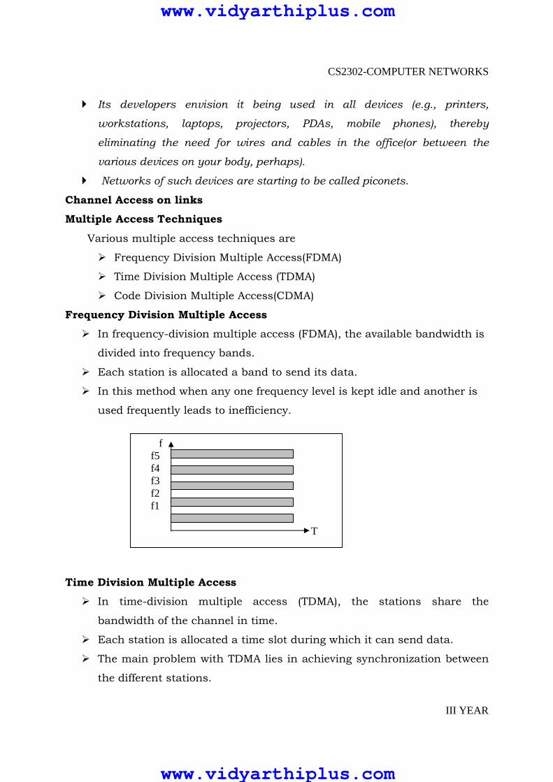
Frequency Division Multiple Access
� In frequency-division multiple access (FDMA), the available bandwidth is
divided into frequency bands.
� Each station is allocated a band to send its data.
� In this method when any one frequency level is kept idle and another is
used frequently leads to inefficiency.
Time Division Multiple Access
� In time-division multiple access (TDMA), the stations share the
bandwidth of the channel in time.
� Each station is allocated a time slot during which it can send data.
� The main problem with TDMA lies in achieving synchronization between
the different stations.
f f5 f4 f3 f2 f1 T
www.vidyarthiplus.com
www.vidyarthiplus.com

CS2302-COMPUTER NETWORKS
III YEAR
� Each station needs to know the beginning of its slot and the location of
its slot.
Code Division Multiple Access
� CDMA differs from FDMA because only one channel occupies the entire
bandwidth of the link.
� It differs from TDMA because all stations can send data at the same time
without timesharing.
� CDMA simply means communication with different codes.
� CDMA is based on coding theory. Each station is assigned a code, which
is a sequence of numbers called chips.
Chips will be added with the original data and it can be transmitted
through same medium.
f f1 f2 f3 f4 f5 f6 T
Code c C5 c4 c3 c2 c1 Frequency f
www.vidyarthiplus.com
www.vidyarthiplus.com

CS2302-COMPUTER NETWORKS
III YEAR
HYBRID MULIPLE ACESS TECHNIQUES 1. Hybrid FDMA/CDMA(FCDMA), 2. Hybrid Direct Sequence/Frequency Hopped Multiple Access(DS/FHMA), 3. Time Division CDMA(TCDMA), 4. Time Division Frequency Hopping(TDFH).
Hybrid FDMA/CDMA(FCDMA)
� The available wideband spectrum is divided into a number of sub spectras with smaller bandwidths. Each of these smaller sub channels becomes a narrowband CDMA system having processing gain lower than the original CDMA system.
� Advantage: the required bandwidth need not be contiguous and different users and be allotted different sub spectrum bandwidths depending on their requirement.
Hybrid Direct Sequence/Frequency Hopped Multiple Access(DS/FHMA)
� This technique consists of a direct sequence modulated signal whose center frequency is made to hop periodically in a pseudorandom fashion.
� Advantage: they avoid the near-far effect. � Disadvantage: they are not adaptable to the soft handoff process.
www.vidyarthiplus.com
www.vidyarthiplus.com
CS2302-COMPUTER NETWORKS
III YEAR
Time Division CDMA(TCDMA)
� Different spreading codes are assigned to different cells. Within each cell, only one user per cell is allotted a particular time slot. Thus at any time, only one CDMA user is transmitting in each cell. When a handoff takes place, the spreading code of the user is changed to that of the new cell.
� Advantage: it avoids the near-far effect.
Time Division Frequency Hopping(TDFH)
� The subscriber can hop to a new frequency at the start of a new TDMA frame. In GSM standard, hopping sequence is predefined and the subscriber is allowed to hop only on certain frequencies which are assigned to a cell.
� Advantage:
◦ Avoiding a severe fade or erasure event on a particular channel.
◦ Avoiding the co-channel interference problems between neighboring cells if two interfering base station transmitters are made to transmit on different frequencies at different times.
Issues in the data link layer
Framing
To transmit frames over the node it is necessary to mention start and
end of each frame. There are three techniques to solve this frame
� Byte-Oriented Protocols (BISYNC, PPP, DDCMP)
� Bit-Oriented Protocols (HDLC)
� Clock-Based Framing (SONET)
Byte Oriented protocols
In this, view each frame as a collection of bytes (characters) rather
than a collection of bits. Such a byte-oriented approach is exemplified by the
BISYNC (Binary Synchronous Communication) protocol and the DDCMP
(Digital Data Communication Message Protocol)
www.vidyarthiplus.com
www.vidyarthiplus.com
CS2302-COMPUTER NETWORKS
III YEAR
Sentinel Approach
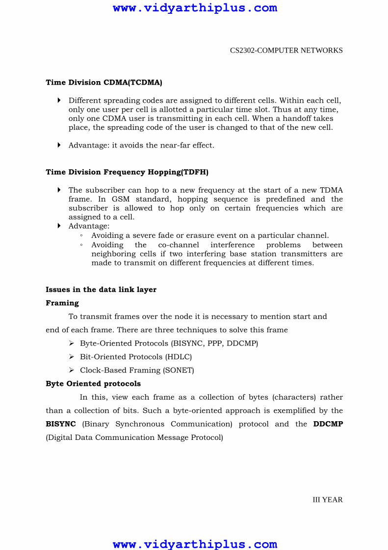
The BISYNC protocol illustrates the sentinel approach to framing; its
frame format is
Fig: BISYNC Frame format
� The beginning of a frame is denoted by sending a special SYN
(synchronization) character.
� The data portion of the frame is then contained between special
sentinel characters: STX (start of text) and ETX (end of text).
� The SOH (start of header) field serves much the same purpose as the
STX field.
� The frame format also includes a field labeled CRC (cyclic redundancy
check) that is used to detect transmission errors.
The problem with the sentinel approach is that the ETX character might
appear in the data portion of the frame. BISYNC overcomes this problem by
“escaping” the ETX character by preceding it with a DLE (data-link-escape)
character whenever it appears in the body of a frame; the DLE character is also
escaped (by preceding it with an extra DLE) in the frame body. This approach is
called character stuffing.
Point-to-Point Protocol (PPP)
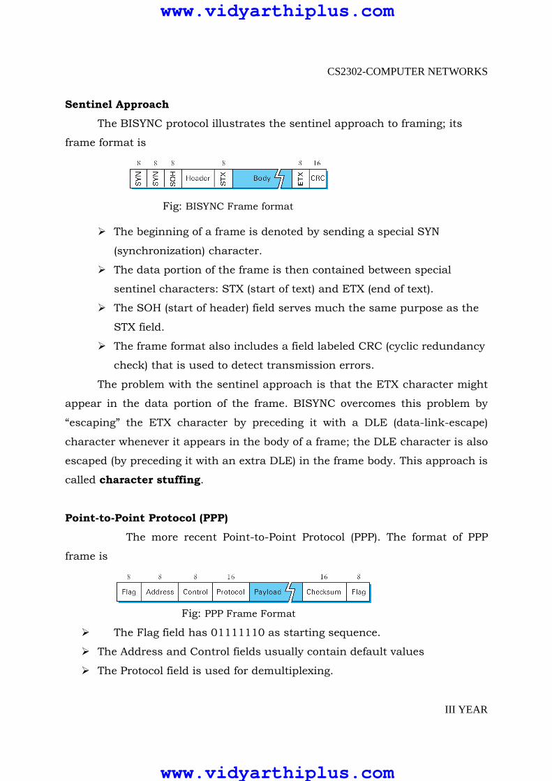
The more recent Point-to-Point Protocol (PPP). The format of PPP
frame is
Fig: PPP Frame Format
� The Flag field has 01111110 as starting sequence.
� The Address and Control fields usually contain default values
� The Protocol field is used for demultiplexing.
www.vidyarthiplus.com
www.vidyarthiplus.com
CS2302-COMPUTER NETWORKS
III YEAR
� The frame payload size can he negotiated, but it is 1500 bytes by default.
� The PPP frame format is unusual in that several of the field sizes are
negotiated rather than fixed.
� Negotiation is conducted by a protocol called LCP (Link Control Protocol).
� LCP sends control messages encapsulated in PPP frames—such
messages are denoted by an LCP identifier in the PPP Protocol.
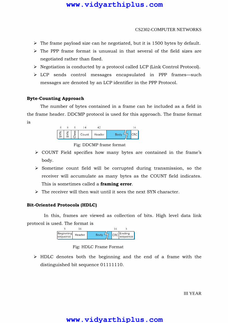
Byte-Counting Approach
The number of bytes contained in a frame can he included as a field in
the frame header. DDCMP protocol is used for this approach. The frame format
is
Fig: DDCMP frame format
� COUNT Field specifies how many bytes are contained in the frame’s
body.
� Sometime count field will be corrupted during transmission, so the
receiver will accumulate as many bytes as the COUNT field indicates.
This is sometimes called a framing error.
� The receiver will then wait until it sees the next SYN character.
Bit-Oriented Protocols (HDLC) In this, frames are viewed as collection of bits. High level data link
protocol is used. The format is
Fig: HDLC Frame Format
� HDLC denotes both the beginning and the end of a frame with the
distinguished bit sequence 01111110.
www.vidyarthiplus.com
www.vidyarthiplus.com
CS2302-COMPUTER NETWORKS
III YEAR
� This sequence might appear anywhere in the body of the frame, it can be
avoided by bit stuffing.
� On the sending side, any time five consecutive 1’s have been transmitted
from the body of the message (i.e., excluding when the sender is trying to
transmit the distinguished 01111110 sequence), the sender inserts a 0
before transmitting the next bit.
� On the receiving side, five consecutive 1’s arrived, the receiver makes its
decision based on the next bit it sees (i.e., the bit following the five is).
� If the next bit is a 0, it must have been stuffed, and so the receiver
removes it. If the next bit is a 1, then one of two things is true, either this
is the end-of-frame marker or an error has been introduced into the bit
stream.
� By looking at the next bit, the receiver can distinguish between these two
cases:
8 If it sees a 0 (i.e., the last eight bits it has looked at are 01111110), then
it is the end-of- frame marker.
9 If it sees a 1 (i.e., the last eight bits it has looked at are 01111111), then
there must have been an error and the whole frame is discarded.
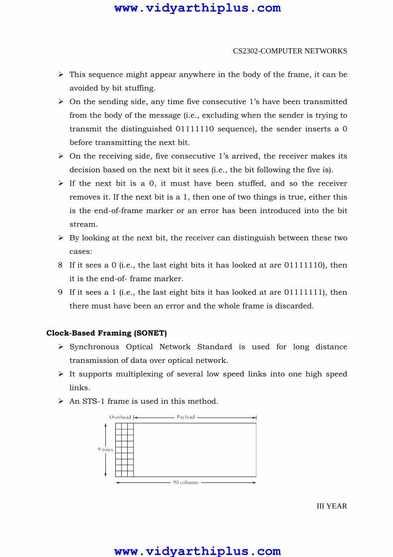
Clock-Based Framing (SONET)
� Synchronous Optical Network Standard is used for long distance
transmission of data over optical network.
� It supports multiplexing of several low speed links into one high speed
links.
� An STS-1 frame is used in this method.
www.vidyarthiplus.com
www.vidyarthiplus.com

CS2302-COMPUTER NETWORKS
III YEAR
� It is arranged as nine rows of 90 bytes each, and the first 3 bytes of each
row are overhead, with the rest being available for data.
� The first 2 bytes of the frame contain a special bit pattern, and it is
these bytes that enable the receiver to determine where the frame starts.
� The receiver looks for the special bit pattern consistently, once in every
810 bytes, since each frame is 9 x 90 = 810 bytes long.
� The STS-N frame can he thought of as consisting of N STS-1 frames,
where the bytes from these frames are interleaved; that is, a byte from
the first frame is transmitted, then a byte from the second frame is
transmitted, and so on.
� Payload from these STS-1 frames can he linked together to form a larger
STS-N payload, such a link is denoted STS-Nc. One of the bit in overhead
is used for this purpose.
� One of the things we are not describing due to the complexity of SONET
is the detailed use of all the other overhead bytes.
� The overhead bytes of a SONET frame are encoded using NRZ,this is the
simple encoding where 1s are high and 0s are low.
SONET frames out of phase.
www.vidyarthiplus.com
www.vidyarthiplus.com

CS2302-COMPUTER NETWORKS
III YEAR
Error Detection and Correction
Data can be corrupted during transmission. For reliable communication, errors must be detected and corrected. Types of Errors Single-bit error
The term Single-bit error means that only one bit of a given data unit
(such as byte, character, data unit or packet) is changed from 1 to 0 or from 0
to 1.
Burst Error
The term Burst Error means that two or more bits in the data unit have
changed from 1 to 0 or from 0 to 1.
Redundancy
One method is to send every data twice, so that receiver checks every
bit of two copies and detect error.
Drawbacks
� Sends n-redundant bits for n-bit message.
� Many errors are undetected if both the copies are corrupted.
Instead of adding entire data, some bits are appended to each unit.
This is called redundant bit because the bits added will not give any
new information. These bits are called error detecting codes
www.vidyarthiplus.com
www.vidyarthiplus.com

CS2302-COMPUTER NETWORKS
III YEAR
ERROR DETECTION
� Bit errors are sometimes introduced into frames. This happens, for
example, because of electrical interference or thermal noise.
� Although errors are rare, especially on optical links, some mechanism is
needed to detect these errors so that corrective action can be taken.
� Detecting errors is only one part of the problem. The other part is
correcting errors once detected.
� There are two basic approaches that can be taken when the recipient of a
message detects an error.
� One is to notify the sender that the message was corrupted so that the
sender can retransmit a copy of the message. If bit errors are rare, then
in all probability the retransmitted copy will be error-free.
� Alternatively, there are some types of error detection algorithms that
allow the recipient to reconstruct the correct message even after it has
been corrupted; such algorithms rely on error-correcting codes.
Error Detection Techniques
� One of the most common techniques for detecting transmission errors is
a technique known as the cyclic redundancy check (CRC). It is used in
nearly all the link-level protocols discussed in the previous section—for
example, HDLC, DDCMP—as well as in the CSMA and token ring
protocols described.
� Two simpler schemes that are also widely used: two-dimensional parity
and checksums.
� The two dimensional parity checksum is used by the BISYNC protocol
when it is transmitting ASCII characters(CRC is used as the error code
when BISYNC is used to transmit EBCDIC), and the latter is used by
several Internet protocols.
� The basic idea behind any error detection scheme is to add redundant
information to a frame that can be used to determine if errors have been
introduced.
www.vidyarthiplus.com
www.vidyarthiplus.com

CS2302-COMPUTER NETWORKS
III YEAR
� In the extreme, we could imagine transmitting two complete copies of
the data. If the two copies are identical at the receiver, then it is probably
the case that both are correct.
� If they differ, then an error was introduced into one (or both) of them,
and they must be discarded. This is a rather poor error detection scheme
for two reasons.
� First, it sends n redundant bits for an n-bit message. Second, many errors
will go undetected—any error that happens to corrupt the same bit
positions in the first and second copies of the message.
� Fortunately, we can do a lot better than this simple scheme. In general,
we can provide quite strong error detection capability while sending only
k redundant bits for an n-bit message, where k ≪ n.
� On an Ethernet, for example, a frame carrying up to12,000 bits (1500
bytes) of data requires only a 32-bit CRC code, or as it is commonly
expressed, uses CRC-32. Such a code will catch the overwhelming
majority of errors.
� We say that the extra bits we send are redundant because they add no
new information to the message. Instead, they are derived directly from
the original message using some well-defined algorithm. Both the sender
and the receiver know exactly what that algorithm is.
� The sender applies the algorithm to the message to generate the
redundant bits. It then transmits both the message and those few extra
bits.
� When the receiver applies the same algorithm to the received message, it
should (in the absence of errors) come up with the same result as the
sender.
� It compares the result with the one sent to it by the sender. If they
match, it can conclude (with high likelihood) that no errors were
introduced in the message during transmission.
www.vidyarthiplus.com
www.vidyarthiplus.com
CS2302-COMPUTER NETWORKS
III YEAR
� If they do not match, it can be sure that either the message or the
redundant bits were corrupted, and it must take appropriate action, that
is, discarding the message, or correcting it if that is possible.
� One note on the terminology for these extra bits. In general, they are
referred to as error-detecting codes. In specific cases, when the algorithm
to create the code is based on addition, they may be called a checksum
Types
Two dimensional parity check
Checksum
Cyclic redundancy check
Two-Dimensional Parity
� It is based on “simple”(one-dimensional) parity.
One dimensional parity
� Which usually involves adding one extra bit to a 7-bit code to balance the
number of 1s in the byte.
� For example, odd parity sets the eighth bit to1 if needed to give an odd
number of 1s in the byte, and even parity sets the eighth bit to 1 if
needed to give an even number of 1s in the byte.
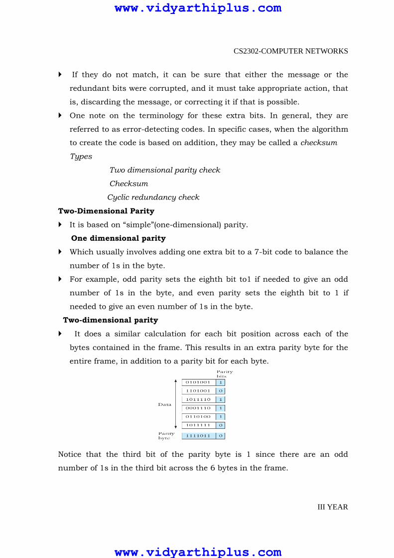
Two-dimensional parity
� It does a similar calculation for each bit position across each of the
bytes contained in the frame. This results in an extra parity byte for the
entire frame, in addition to a parity bit for each byte.
Notice that the third bit of the parity byte is 1 since there are an odd
number of 1s in the third bit across the 6 bytes in the frame.
www.vidyarthiplus.com
www.vidyarthiplus.com
CS2302-COMPUTER NETWORKS
III YEAR
Internet Checksum Algorithm
� The idea behind the Internet checksum is very simple—you add up all
the words that are transmitted and then transmit the result of that sum.
The result is called the checksum.
� The receiver performs the same calculation on the received data and
compares the result with the received checksum.
� If any transmitted data, including the checksum itself, is corrupted, then
the results will not match, so the receiver knows that an error occurred.
� You can imagine many different variations on the basic idea of a
checksum. The exact scheme used by the Internet protocols works as
follows. Consider the data being check summed as a sequence of 16-bit
integers. Add them together using 16-bit ones complement arithmetic
(explained below) and then take the ones complement of the result. That
16-bit number is the checksum.
� In ones complement arithmetic, a negative integer −x is represented as
the complement of x; that is, each bit of x is inverted. When adding
numbers in ones complement arithmetic, a carryout from the most
significant bit needs to be added to the result.
� Consider, for example, the addition of −5 and −3 in ones complement
arithmetic on 4-bit integers. +5 is 0101, so −5 is 1010; +3 is 0011, so −3
is 1100.
� If we add 1010 and 1100 ignoring the carry, we get 0110. In ones
complement arithmetic, the fact that this operation caused a carry from
the most significant bit causes us to increment the result, giving 0111,
which is the ones complement representation of −8 (obtained by inverting
the bits in 1000), as we would expect.
www.vidyarthiplus.com
www.vidyarthiplus.com
CS2302-COMPUTER NETWORKS
III YEAR
Routine to implement internet checksum algorithm
u_short
cksum(u_short *buf, int count)
{
register u_long sum = 0;
while (count--)
{
sum += *buf++;
if (sum & 0xFFFF0000)
{
/* carry occurred,
so wrap around */
sum &= 0xFFFF;
sum++;
}
}
return ˜ (sum & 0xFFFF);
}
� For example, a pair of single-bit errors,one of which increments a word,
one of which decrements another word by the same amount, will go
undetected.
� The reason for using an algorithm like this in spite of its relatively weak
protection against errors (compared to a CRC, for example) is simple,
This algorithm is much easier to implement in software.
Cyclic Redundancy Check
� It should be clear by now that a major goal in designing error detection
algorithms is to maximize the probability of detecting errors using only a
small number of redundant bits.
www.vidyarthiplus.com
www.vidyarthiplus.com

CS2302-COMPUTER NETWORKS
III YEAR
� Cyclic redundancy checks use some fairly powerful mathematics to
achieve this goal. For example, a 32-bit CRC gives strong protection
against common bit errors in messages that are thousands of bytes long.
� We can thus think of a sender and a receiver as exchanging polynomials
with each other.
� For example, an 8-bit message consisting of the bits 10011010
corresponds to the polynomial
M(x) = 1 × x7 + 0 × x6 + 0 × x5 + 1 × x4+1 × x3 + 0 × x2 + 1 × x1+0 × x0
= x7 + x4 + x3 + x1
� For the purposes o f calculating a CRC, a sender and receiver have to
agree on a divisor polynomial, C(x). C(x) is a polynomial of degree k.
For example, suppose
C(x) = x3 + x2 + 1. In this case, k = 3.
� When a sender wishes to transmit a message M(x) that is n + 1 bits long,
what is actually sent is the (n + 1)-bit message plus k bits. We call the
complete transmitted message, including the redundant bits,P(x).
� If P(x) is transmitted over a link and there are no errors introduced during
transmission, then the receiver should be able to divide P(x) by C(x)
exactly, leaving a remainder of zero.
� On the other hand, if some error is introduced into P(x) during
transmission, then in all likelihood the received polynomial will no longer
be exactly divisible by C(x), and thus the receiver will obtain a nonzero
remainder, implying that an error has occurred.
Polynomial Properties
1. Any polynomial B(x) can be divided by a divisor polynomial C(x) if B(x) is of
higher degree than C(x).
2. Any polynomial B(x) can be divided once by a divisor polynomial C(x) if
B(x) is of the same degree as C(x).
3. The remainder obtained when B(x) is divided by C(x) is obtained by
subtracting C(x) from B(x).
www.vidyarthiplus.com
www.vidyarthiplus.com
CS2302-COMPUTER NETWORKS
III YEAR
4. To subtract C(x) from B(x), we simply perform the exclusive-OR (XOR)
operation on each pair of matching coefficients.
� For example, the polynomial x3 +1 can be divided by x3 + x2 +1 (because
they are both of degree 3) and the remainder would be
0×x3+1×x2+0×x1+0×x0 = x2(obtained by XORing the coefficients of each
term).
� In terms of messages, we could say that 1001 can be divided by 1101
and leaves a remainder of 0100. You should be able to see that the
remainder is just the bitwise exclusive-OR of the two messages.
� Recall that we wanted to create a polynomial for transmission that is
derived from the original message M(x), is k bits longer than M(x), and is
exactly divisible by C(x).
� We can do this in the following way:
1. Multiply M(x) by xk; that is, add k zeroes at the end of the message.
Call this zero-extended message T(x).
2 .Divide T(x) by C(x) and find the remainder.
3 .Subtract the remainder from T(x).
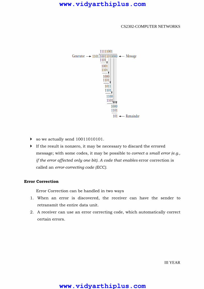
� Consider the message x7 + x4 + x3 + x1, or 10011010. We begin by
multiplying by x3, since our divisor polynomial is of degree 3. This gives
10011010000.
� We divide this by C(x), which corresponds to 1101 in this case.
� that the remainder of the example calculation is 101. So we know that
10011010000 minus 101 would be exactly divisible by C(x), and this is
what we send.
� so we actually send 10011010101.
� If the result is nonzero, it may be necessary to discard the errored
message; with some codes, it may be possible to correct a small error (e.g.,
if the error affected only one bit). A code that enables error correction is
called an error-correcting code (ECC).
www.vidyarthiplus.com
www.vidyarthiplus.com
CS2302-COMPUTER NETWORKS
III YEAR
� so we actually send 10011010101.
� If the result is nonzero, it may be necessary to discard the errored
message; with some codes, it may be possible to correct a small error (e.g.,
if the error affected only one bit). A code that enables error correction is
called an error-correcting code (ECC).
Error Correction Error Correction can be handled in two ways
1. When an error is discovered, the receiver can have the sender to
retransmit the entire data unit.
2. A receiver can use an error correcting code, which automatically correct
certain errors.
www.vidyarthiplus.com
www.vidyarthiplus.com

CS2302-COMPUTER NETWORKS
III YEAR
Error correcting codes are more sophisticated than error-detection codes and
require more redundancy bits.
In single bit error detection only two states are sufficient.
1) error
2) no error
Two states are not enough to detect an error but not to correct it.
Redundancy Bits
� To calculate the number of redundancy bit(r) required to correct a
given number of data bits (m), we must find a relationship between m
and r.
� Add m bits of data with r bits. The length of the resulting code is m+r.
Data and Redundancy bits
� If the total number of bits are m+r, then r must be able to indicate at
least m+r+1 different states. r bits can indicate 2r different states.
Therefore, 2r must be equal to or greater than m+r+1
2r >=m+r+1
� For example if the value of m is 7 the smallest r value that can satisfy
this equation is 4.
www.vidyarthiplus.com
www.vidyarthiplus.com
CS2302-COMPUTER NETWORKS
III YEAR
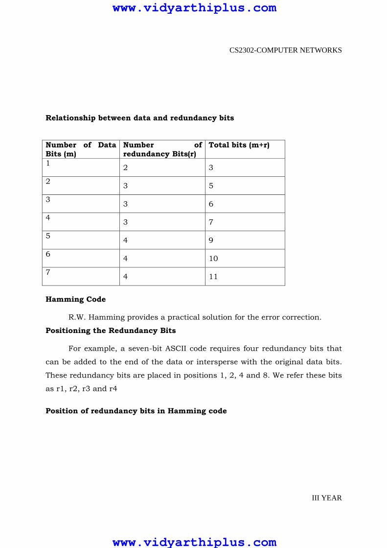
Relationship between data and redundancy bits
Number of Data Bits (m)
Number of redundancy Bits(r)
Total bits (m+r)
1
2 3
2
3 5
3
3 6
4
3 7
5
4 9
6
4 10
7
4 11
Hamming Code
R.W. Hamming provides a practical solution for the error correction.
Positioning the Redundancy Bits
For example, a seven-bit ASCII code requires four redundancy bits that
can be added to the end of the data or intersperse with the original data bits.
These redundancy bits are placed in positions 1, 2, 4 and 8. We refer these bits
as r1, r2, r3 and r4
Position of redundancy bits in Hamming code
www.vidyarthiplus.com
www.vidyarthiplus.com

CS2302-COMPUTER NETWORKS
III YEAR
The combination used to calculate each of the four r values for a seven-bit data
sequence are as follows
� The r1 bit is calculated using all bits positions whose binary
representation include a 1 in the rightmost position
� r2 is calculated using all bit position with a 1 in the second position
and so on
r1: bits 1,3,5,7,9,11
r2: bits 2, 3, 6, 7, 10, 11
r3: bits 4, 5, 6, 7
r4: bits 8, 9, 10, 11
Redundancy bits calculation
www.vidyarthiplus.com
www.vidyarthiplus.com
CS2302-COMPUTER NETWORKS
III YEAR
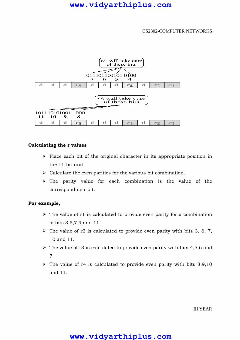
Calculating the r values
� Place each bit of the original character in its appropriate position in
the 11-bit unit.
� Calculate the even parities for the various bit combination.
� The parity value for each combination is the value of the
corresponding r bit.
For example,
� The value of r1 is calculated to provide even parity for a combination
of bits 3,5,7,9 and 11.
� The value of r2 is calculated to provide even parity with bits 3, 6, 7,
10 and 11.
� The value of r3 is calculated to provide even parity with bits 4,5,6 and
7.
� The value of r4 is calculated to provide even parity with bits 8,9,10
and 11.
www.vidyarthiplus.com
www.vidyarthiplus.com
CS2302-COMPUTER NETWORKS
III YEAR
LINK LEVEL FLOW CONTROL
� As we saw in the previous section, frames are sometimes corrupted while
in transit, with an error code like CRC used to detect such errors. While
some error codes are strong enough also to correct errors, in practice the
overhead is typically too large to handle the range of bit and burst errors
that can be introduced on a network link.
� Even when error-correcting codes are used (e.g., on wireless links), some
errors will be too severe to be corrected. As a result, some corrupt frames
must be discarded.
� A link-level protocol that wants to deliver frames reliably must somehow
recover from these discarded (lost) frames.
� This is usually accomplished using a combination of two fundamental
mechanisms—acknowledgments and timeouts.
� An acknowledgment (ACK for short)is a small control frame that a
protocol sends back to its peer saying that it has received an earlier
frame.
� If the sender does not receive an acknowledgment after a reasonable
amount of time, then it retransmits the original frame. This action of
waiting a reasonable amount of time is called a timeout.
� The general strategy of using acknowledgments and timeouts to
implement reliable delivery is sometimes called automatic repeat request
(normally abbreviated ARQ).
www.vidyarthiplus.com
www.vidyarthiplus.com
CS2302-COMPUTER NETWORKS
III YEAR
Stop-and-Wait
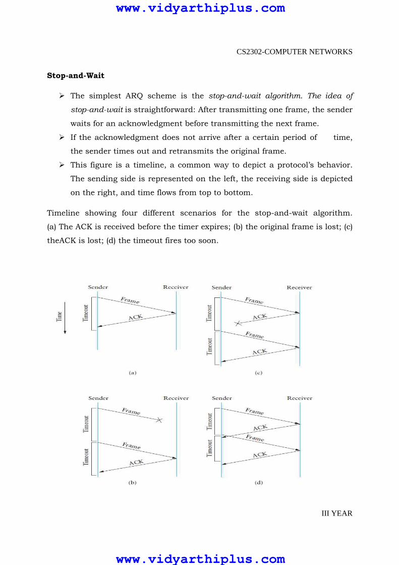
� The simplest ARQ scheme is the stop-and-wait algorithm. The idea of
stop-and-wait is straightforward: After transmitting one frame, the sender
waits for an acknowledgment before transmitting the next frame.
� If the acknowledgment does not arrive after a certain period of time,
the sender times out and retransmits the original frame.
� This figure is a timeline, a common way to depict a protocol’s behavior.
The sending side is represented on the left, the receiving side is depicted
on the right, and time flows from top to bottom.
Timeline showing four different scenarios for the stop-and-wait algorithm.
(a) The ACK is received before the timer expires; (b) the original frame is lost; (c)
theACK is lost; (d) the timeout fires too soon.
www.vidyarthiplus.com
www.vidyarthiplus.com

CS2302-COMPUTER NETWORKS
III YEAR
Figure
(a) shows the situation in which the ACK is received before the timer expires.
(b) show the situation in which original frame lost.
(c) shows the situation in which acknowledgement lost.
(d) shows the situation in wh.ich the timeout fires too soon
In the case of ( c) and (d)
In both cases, the sender times out and retransmits the original frame. but
the receiver will think that it is the next frame, since it correctly received
and acknowledged the first frame.
This has the potential to cause duplicate copies of a frame to be delivered.
To address this problem, the header for a stop-and-wait protocol usually
includes a 1-bit sequence number—that is, the sequence number can take
on the values 0 and 1—and the sequence numbers used for each frame
alternate.
www.vidyarthiplus.com
www.vidyarthiplus.com

CS2302-COMPUTER NETWORKS
III YEAR
� The main shortcoming of the stop-and-wait algorithm is that it allows the
sender to have only one outstanding frame on the link at a time, and this
may be far below the link’s capacity. Consider, for example, a 1.5-Mbps
link with a 45-ms round-trip time.
� This link has a delay × bandwidth product of 67.5 Kb, or approximately 8
KB.Since the sender can send only one frame per RTT, and assuming a
frame size of 1 KB,this implies a maximum sending rate of
BitsPerFrame ÷ TimePerFrame
= 1024 × 8 ÷ 0.045
= 182 Kbps
This algorithm is using only one-eighth of the link ‘capacity.
� To use the link fully, then, we’d like the sender to be able to transmit up
to eight fram.es before having to wait for an acknowledgment.
� We would like to be able to send this much data without waiting for the
first acknowledgment. The principle at work here is often referred to as
keeping the pipe full.
� The algorithm that allows us to do this is called sliding window.
Sliding Window Algorithm
� The sliding window algorithm works as follows. First, the sender assigns
a sequence number, denoted SeqNum, to each frame. For now, let’s ignore
the fact that SeqNum is implemented by a finite-size header field and
instead assume that it can grow infinitely large.
� The sender maintains three variables: The send window size, denoted
SWS,gives the upper bound on the number of outstanding
(unacknowledged) frames that the sender can transmit; LAR denotes the
www.vidyarthiplus.com
www.vidyarthiplus.com
CS2302-COMPUTER NETWORKS
III YEAR
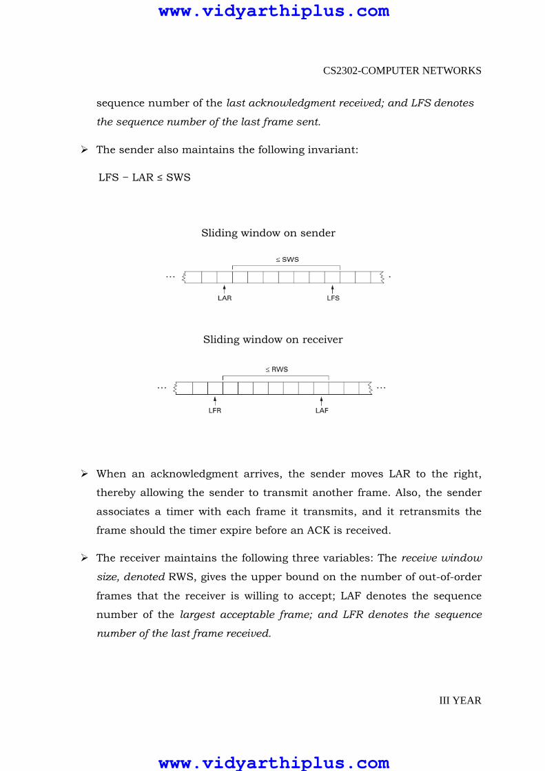
sequence number of the last acknowledgment received; and LFS denotes
the sequence number of the last frame sent.
� The sender also maintains the following invariant:
LFS − LAR ≤ SWS
Sliding window on sender
Sliding window on receiver
� When an acknowledgment arrives, the sender moves LAR to the right,
thereby allowing the sender to transmit another frame. Also, the sender
associates a timer with each frame it transmits, and it retransmits the
frame should the timer expire before an ACK is received.
� The receiver maintains the following three variables: The receive window
size, denoted RWS, gives the upper bound on the number of out-of-order
frames that the receiver is willing to accept; LAF denotes the sequence
number of the largest acceptable frame; and LFR denotes the sequence
number of the last frame received.
www.vidyarthiplus.com
www.vidyarthiplus.com
CS2302-COMPUTER NETWORKS
III YEAR
� The receiver also maintains the following invariant:
LAF − LFR ≤ RWS
� When a frame with sequence number SeqNum arrives, the receiver takes
the following action.
� If SeqNum ≤ LFR or SeqNum > LAF, then the frame is outside the
receiver’s window and it is discarded.
� If LFR < SeqNum ≤ LAF, then the frame is within the receiver’s window
and it is accepted.
� Now the receiver needs to decide whether or not to send an ACK.
� Let SeqNumToAck denote the largest sequence number not yet
acknowledged, such that all frames with sequence numbers less than or
equal to SeqNumToAck have been received. The receiver acknowledges
the receipt of SeqNumToAck, even if higher-numbered packets have been
received.
� This acknowledgment is said to be cumulative. It then sets LFR =
SeqNumToAckand adjusts
LAF = LFR + RWS.
� For example, suppose LFR = 5 (i.e., the last ACK the receiver sent was for
sequence number 5), and RWS = 4.This implies that LAF =9.
� Should frames 7 and 8 arrive, they will be buffered because they are
within the receiver’s window. However, no ACK needs to be sent since
frame 6 is yet to arrive.
� Frames 7 and 8 are said to have arrived out of order. (Technically, the
receiver could resend an ACK for frame 5 when frames 7 and 8 arrive.)
www.vidyarthiplus.com
www.vidyarthiplus.com

CS2302-COMPUTER NETWORKS
III YEAR
� Should frame 6 then arrive—perhaps it is late because it was lost the
first time and had to be retransmitted, or perhaps it was simply
delayed—the receiver acknowledges frame 8, bumps LFR to 8, and sets
LAF to 12. If frame 6 was in fact lost, then a timeout will have occurred
at the sender, causing it to retransmit frame 6.
� We observe that when a timeout occurs, the amount of data in transit
decreases,since the sender is unable to advance its window until frame 6
is acknowledged.
� This means that when packet losses occur, this scheme is no longer
keeping the pipe full.
� The longer it takes to notice that a packet loss has occurred, the more
severe this problem becomes.
� Notice that in this example, the receiver could have sent a negative
acknowledgment (NAK) for frame 6 as soon as frame 7 arrived. However,
this is unnecessary since the sender’s timeout mechanism is sufficient to
catch this situation, and sending NAKs adds additional complexity to the
receiver.
� Also, as we mentioned, it would have been legitimate to send additional
acknowledgments of frame 5 when frames 7and 8 arrived; in some cases,
a sender can use duplicate ACKs as a clue that a frame was lost. Both
approaches help to improve performance by allowing early detection of
packet losses.
� Yet another variation on this scheme would be to use selective
acknowledgments. That is, the receiver could acknowledge exactly those
frames it has received, rather than just the highest-numbered frame
received in order. So, in the above example, the receiver could
acknowledge the receipt of frames 7 and 8.
� Giving more information to the sender makes it potentially easier for the
sender to keep the pipe full, but adds complexity to the implementation.
www.vidyarthiplus.com
www.vidyarthiplus.com

CS2302-COMPUTER NETWORKS
III YEAR
� The sending window size is selected according to how many frames we
want to have outstanding on the link at a given time; SWS is easy to
compute for a given delay×bandwidth product.1 On the other hand, the
receiver can set RWS to whatever it wants. Two common settings are
RWS = 1, which implies that the receiver will not buffer any frames that
arrive out of order, and RWS = SWS, which implies that the receiver can
buffer any of the frames the sender transmits.
Finite Sequence Numbers and Sliding Window
� We now return to the one simplification we introduced into the
algorithm—our assumption that sequence numbers can grow infinitely
large. In practice, of course, a frame’s sequence number is specified in a
header field of some finite size.
� For example,a 3-bit field means that there are eight possible sequence
numbers, 0 . . . 7.
� This makes it necessary to reuse sequence numbers or, stated another
way, sequence numbers wraparound.
� Suppose we have one more number in our space of sequence numbers
than we have potentially outstanding frames; that is,
� SWS ≤ MaxSeqNum − 1, where MaxSeqNum is the number of available
sequence numbers. (for example sws <=7-1,where 7 is a maximum
sequence number)
� Is this sufficient? The answer depends on RWR. If RWS = 1, then
MaxSeqNum ≥ SWS + 1 is sufficient.
� If RWS is equal to SWS, then having a MaxSeqNum just one greater
than the sending window size is not good enough.
� To see this, consider the situation in which we have the eight sequence
numbers 0 through 7, and SWS = RWS = 7.
www.vidyarthiplus.com
www.vidyarthiplus.com

CS2302-COMPUTER NETWORKS
III YEAR
� Suppose the sender transmits frames 0..6, they are successfully received,
but the ACKs are lost.
� The receiver is now expecting frames 7, but the sender times out and
sends frames 0..6.
� Unfortunately, the receiver is expecting the second incarnation of frames
0..6, but gets the first incarnation of these frames.
� This is exactly the situation we wanted to avoid. It turns out that the
sending window size can be no more than half as big as the number of
available sequence numbers when RWS = SWS, or stated more precisely,
SWS < (MaxSeqNum + 1)/2
� Intuitively, what this is saying is that the sliding window protocol
alternates between the two halves of the sequence number space, just as
stop-and-wait alternates between sequence numbers 0 and 1.
� The only difference is that it continually slides between the two halves
rather than discretely alternating between them.
� Note that this rule is specific to the situation where RWS = SWS.
� We leave it as an exercise to determine the more general rule that works
for arbitrary values of RWS and SWS.
� Also note that the relationship between the window size and the
sequence number space depends on an assumption that is so obvious
that it is easy to overlook, namely, that frames are not reordered in
transit. This cannot happen on a direct point-to-point link since there is
no way for one frame to overtake another during transmission.
*************************************ALL THE BEST*********************************
www.vidyarthiplus.com
www.vidyarthiplus.com