computer organization and architecture major advances...
TRANSCRIPT

1
Chapter 13Reduced Instruction Set Computers (RISC)
Computer Organization and Architecture Major Advances in Computers(1)
• The family concept— IBM System/360 1964— DEC PDP-8— Separates architecture from implementation
• Microprogrammed control unit— Idea by Wilkes 1951— Produced by IBM S/360 1964— Simplifies design and implementation of control unit
• Cache memory— IBM S/360 model 85 1969
Major Advances in Computers(2)
• Solid State RAM— (See memory notes)
• Microprocessors— Intel 4004 1971
• Pipelining— Introduces parallelism into fetch execute cycle
• Vector processing— Explicit parallelism
• Multiple processors• RISC design
RISC
• Reduced Instruction Set Computer— A dramatic departure from historical architectures
• Key features— Large number of general purpose registers— or use of compiler technology to optimize register
use— Limited and simple instruction set— Emphasis on optimizing the instruction pipeline
Comparison of Processors Driving force for CISC
• Software costs far exceed hardware costs• Increasingly complex high level languages• Semantic gap: hard to translate from HLL
semantics to machine semantics• Leads to:
— Large instruction sets— More addressing modes— Hardware implementations of HLL statements
– e.g. CASE (switch) in VAX– LOOP in Intel x86

2
Intent of CISC
• Ease compiler writing• Improve execution efficiency
— Complex operations in microcode
• Support more complex HLLs
Execution Characteristics
• Operations performed— Determine functions to be performed by processor
and its interaction with memory
• Operands used— Determine instruction format and addressing modes
• Execution sequencing— Determines control and pipeline organization
• Studies have been done based on programs written in HLLs
• Dynamic studies are measured during the execution of the program
Operations
• Assignments— Movement of data
• Conditional statements (IF, LOOP)— Sequence control
• Procedure call-return is very time consuming• Some HLL instructions lead to many machine
code operations
Weighted Relative Dynamic Frequency of HLL Operations
•Weights
—Machine instruction: Multiply cols 2 & 3 by number of machine instructions
—Memory reference: Multiply cols 2 & 3 by number of memory references
Operands
• Mainly local scalar variables• Optimisation should concentrate on accessing
local variables
Pascal C Average
Integer Constant 16% 23% 20%
Scalar Variable 58% 53% 55%
Array/Structure 26% 24% 25%
Procedure Calls
• Very time consuming operation• Depends on number of parameters passed
— Great majority use few parameters — 90% use three or fewer
• Procedure invocation depth— Fairly shallow for most programs
• Most variables are local and scalar— cache or registers
3
Implications
• Best support is given by optimising most used and most time consuming features
• Large number of registers— To optimize operand referencing
• Careful design of pipelines— Optimal branch handling important
• Simplified (reduced) instruction set
Operands and Registers
• Quick access to operands is desirable. — Many assignment statements— Significant number of operand accesses per HLL
statement
• Register storage is fastest available storage• Addresses are much shorter than memory or
cache• So we’d like to keep operands in registers as
much as possible
Large Register File
• Software approach— Require compiler to allocate registers— Allocate based on most used variables in a given
time— Requires sophisticated program analysis to allocate
registers efficiently — Can be very difficult on architectures such x86
where registers have special purposes
• Hardware approach— Have more registers— Thus more variables will be in registers
Using Registers for Local Variables
• Store local scalar variables in registers to reduces memory access
• Every procedure (function) call changes locality— Save variables in registers— Pass Parameters — Get return results— Restore variables
Register Windows
• Because most calls use only a few parameters and call depth is typically shallow: — Use multiple small sets of registers— Calls will switch to a different set of registers— Returns will switch back to a previously used set of
registers
Register Windows cont.
• We can divide a register set into 3 areas:1. Parameter registers2. Local registers3. Temporary registers
• Temporary registers from one set overlap parameter registers from the next
• This allows parameter passing without actually moving or copying any data
4
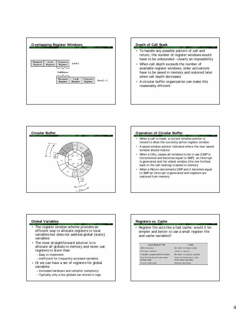
Overlapping Register Windows Depth of Call Stack
• To handle any possible pattern of call and return, the number of register windows would have to be unbounded – clearly an impossibility
• When call depth exceeds the number of available register windows, older activations have to be saved in memory and restored later when call depth decreases
• A circular buffer organization can make this reasonably efficient
Circular Buffer Operation of Circular Buffer• When a call is made, a current window pointer is
moved to show the currently active register window• A saved window pointer indicates where the next saved
window should restore • When a CALL causes all windows to be in use (CWP is
incremented and becomes equal to SWP), an interrupt is generated and the oldest window (the one furthest back in the call nesting) is saved to memory
• When a Return decrements CWP and it becomes equal to SWP an interrupt is generated and registers are restored from memory
Global Variables
• The register window scheme provides an efficient way to allocate registers to local variables but does not address global (static) variables
• The most straightforward solution is to allocate all globals to memory and never use registers to store than— Easy to implement— Inefficient for frequently accessed variables
• Or we can have a set of registers for global variables— Increases hardware and compiler complexity— Typically only a few globals can stored in regs
Registers vs. Cache
• Register file acts like a fast cache; would it be simpler and better to use a small register file and cache variables?
5
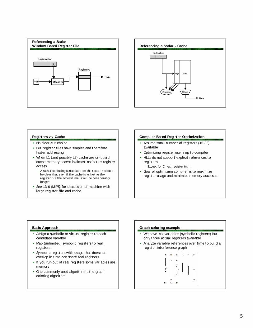
Referencing a Scalar -Window Based Register File Referencing a Scalar - Cache
Registers vs. Cache
• No clear-cut choice • But register files have simpler and therefore
faster addressing• When L1 (and possibly L2) cache are on-board
cache memory access is almost as fast as register access— A rather confusing sentence from the text: “It should
be clear that even if the cache is as fast as the register file the access time is will be considerably longer”
• See 13.6 (MIPS) for discussion of machine with large register file and cache
Compiler Based Register Optimization
• Assume small number of registers (16-32) available
• Optimizing register use is up to compiler• HLLs do not support explicit references to
registers— Except for C – ex. register int i;
• Goal of optimizing compiler is to maximize register usage and minimize memory accesses
Basic Approach
• Assign a symbolic or virtual register to each candidate variable
• Map (unlimited) symbolic registers to real registers
• Symbolic registers with usage that does not overlap in time can share real registers
• If you run out of real registers some variables use memory
• One commonly used algorithm is the graph coloring algorithm
Graph coloring example
• We have six variables (symbolic registers) but only three actual registers available
• Analyze variable references over time to build a register interference graph

6
Graph Coloring
• Given a graph of nodes and edges:— Assign a color to each node— Adjacent nodes have different colors— Use minimum number of colors
• Nodes are symbolic registers• Two registers that are live in the same program
fragment are joined by an edge• Try to color the graph with n colors, where n is
the number of real registers— Nodes that are joined by an edge must have
different colors• Nodes that cannot be colored are allocated in
memory
Graph Coloring Approach
Why CISC (1)?
• Compiler simplification— But complex machine instructions are harder to
exploit well— Machine code optimization is more difficult
• Smaller programs?— Program takes up less memory but…— Memory is now cheap— May not occupy less bits, just look shorter in
symbolic form– More instructions require longer op-codes– Register references require fewer bits
Why CISC (2)?
• Faster programs?— There is a bias towards use of simpler instructions
despite the efficiency of complex instructions— CISC machines need a more complex control unit
and/or larger microprogram control store so simple instructions may take longer to execute
— Note in Pentium that instruction cache is actuallymicrocode storage
– Microcode consists of micro-ops – RISC instructions that execute in the RISC core
RISC Characteristics
• One instruction per machine cycle— Cycle = time needed to fetch two operands from
registers, perform ALU op, store result in register— Simple hardwired instructions need little or no
microcode
• Register to register operations— Reduces variations in instruction set (e.g., VAX has
25 add instructions)— Memory access Load and Store only
RISC Characteristics
• Few, simple addressing modes— Complex addressing modes can by synthesized in
software from simpler ones
• Few, simple instruction formats— Fixed length instruction format— Aligned on word boundaries— Fixed field locations especially the opcode— Simpler decode circuitry
7
RISC vs CISC
• Not clear cut— Many studies fail to distinguish the effect of a large
register file from the effect of RISC instruction set
• Many designs borrow from both philosophies— E.g. PowerPC and Pentium— RISC and CISC appear to be converging
Classic RISC Characteristics in Detail1. A single instruction size, typically 4 bytes2. Small number of addressing modes3. No memory-indirect addressing 4. No operations combine load/store with arithmetic5. No more than one memory addressed operand per
instruction6. Does not support arbitrary (byte) alignment of data
for load/store7. Max number of MMU uses for a data address is 18. At least 5 bits for integer register specifier (32
registers)9. At least 4 bits for FP register specifier (16 registers)
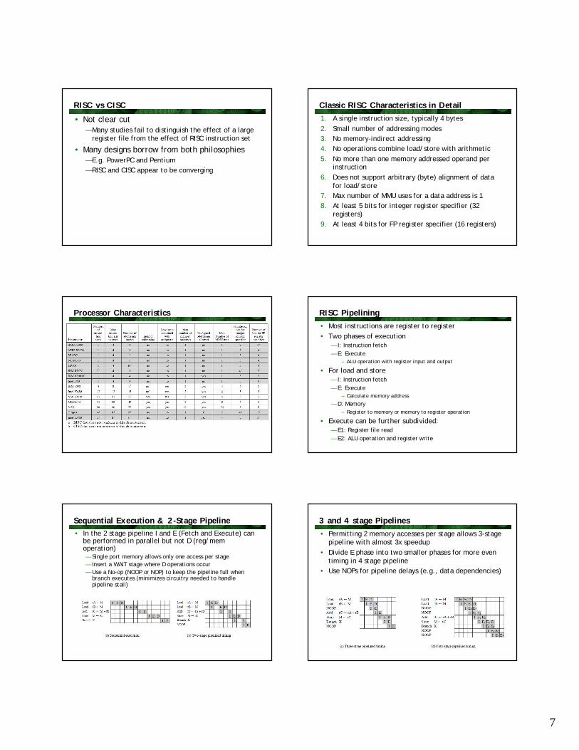
Processor Characteristics RISC Pipelining• Most instructions are register to register• Two phases of execution
— I: Instruction fetch— E: Execute
– ALU operation with register input and output
• For load and store— I: Instruction fetch— E: Execute
– Calculate memory address
— D: Memory– Register to memory or memory to register operation
• Execute can be further subdivided:— E1: Register file read— E2: ALU operation and register write
Sequential Execution & 2-Stage Pipeline• In the 2 stage pipeline I and E (Fetch and Execute) can
be performed in parallel but not D (reg/mem operation)— Single port memory allows only one access per stage— Insert a WAIT stage where D operations occur— Use a No-op (NOOP or NOP) to keep the pipeline full when
branch executes (minimizes circuitry needed to handle pipeline stall)
3 and 4 stage Pipelines• Permitting 2 memory accesses per stage allows 3-stage
pipeline with almost 3x speedup• Divide E phase into two smaller phases for more even
timing in 4 stage pipeline• Use NOPs for pipeline delays (e.g., data dependencies)
8
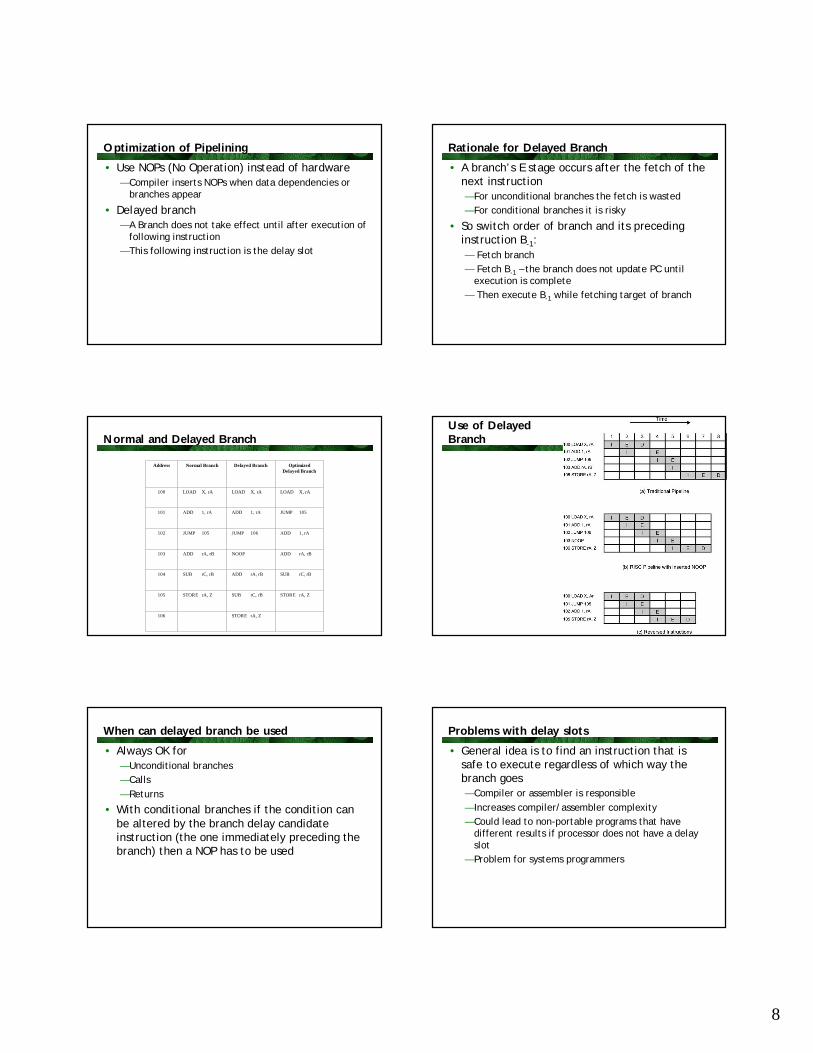
Optimization of Pipelining
• Use NOPs (No Operation) instead of hardware— Compiler inserts NOPs when data dependencies or
branches appear
• Delayed branch— A Branch does not take effect until after execution of
following instruction— This following instruction is the delay slot
Rationale for Delayed Branch
• A branch’s E stage occurs after the fetch of the next instruction — For unconditional branches the fetch is wasted— For conditional branches it is risky
• So switch order of branch and its preceding instruction B-1:— Fetch branch— Fetch B-1 – the branch does not update PC until
execution is complete— Then execute B-1 while fetching target of branch
Normal and Delayed Branch
Address Normal Branch Delayed Branch Optimized Delayed Branch
100 LOAD X, rA LOAD X, rA LOAD X, rA
101 ADD 1, rA ADD 1, rA JUMP 105
102 JUMP 105 JUMP 106 ADD 1, rA
103 ADD rA, rB NOOP ADD rA, rB
104 SUB rC, rB ADD rA, rB SUB rC, rB
105 STORE rA, Z SUB rC, rB STORE rA, Z
106 STORE rA, Z
Use of Delayed Branch
When can delayed branch be used
• Always OK for — Unconditional branches— Calls— Returns
• With conditional branches if the condition can be altered by the branch delay candidate instruction (the one immediately preceding the branch) then a NOP has to be used
Problems with delay slots
• General idea is to find an instruction that is safe to execute regardless of which way the branch goes— Compiler or assembler is responsible— Increases compiler/assembler complexity— Could lead to non-portable programs that have
different results if processor does not have a delay slot
— Problem for systems programmers

9
Delayed Load
• When a load from memory is encountered processor locks target register
• Then continues executing instruction stream until it reaches an instruction that requires the load target
Loop Unrolling
• A compiler technique for improving instruction parallelism
• Repeat body of a loop in code some number of times u (the unrolling factor) and iterate by step u instead of step 1
• Improves performance by— Reduce loop overhead (branching) — Increase parallelism by improving pipeline
performance— Improve register, cache and/or TLB locality
Loop unrolling example• 2nd assignment performed while first is being stored
and loop variable updated• If array elements are in regs then locality of reference
will improve because a[I] and a[I+1] are used twice, reducing loads per iteration from 3 to 2
MIPS R4000
• MIPS Technology Inc developed one of the first commercially available RISC processors
• R4000 is a 64-bit machine— Used for all buses, data paths, registers and addresses
• Major processor units are the CPU and a coprocessor for memory management
• Processor has a very simple architecture— 32 64 bit registers— 64K instruction and data caches (R3000)— Register $0 is a constant 0 — Register $31 is a link register
Scicortex Supercomputer
• Based on MIPS 4000 specification• Each multicore node has:
— 6 MIPS cores— Crossbar memory controller— Interconnect DMA engine— Gigabit ethernet— PCI express controller
• In a single chip that consumes 10 watts of power and is capable of 6 GFLOPs (floating point operations per second)
Instruction Set Design
• All instructions are 32 bits• All data operations are reg/reg• Only memory operations are load and store• No condition code register
— Conditional instructions generate flags in a GP register— No need for special CC handling in a pipeline— Registers subject to same dataflow analysis as normal
operands— Conditions mapped to GP registers are also subject to
compile-time register analysis

10
Instruction Formats Memory Addressing
• Textbook actually discusses the MIPS R3000 instruction set
• Memory references are 16-bit offsets from a 32-bit register
Synthesizing Other addressing modes
• Note limitations on address length imposed by the 32-bit instruction format
Instruction Set (1)
Instruction Set (2) MIPS Pipeline
• First generation RISC processors achieved throughput of almost 1 instruction/clock
• Two classes of processors improve on this: — Superscalar (2 or more separate pipelines)— Superpipelined (more stages in pipeline)
• R4000 is a super-pipelined architecture• Changes from R3000 to R4000 exemplify
modern pipeline technology

11
R3000 Pipeline
• Advances once per clock cycle• MIPS compilers can fill delay slot ~80% of the
the time• Five stages:
— Instruction fetch— Source operand fetch from register file— ALU operation or data operand address generation— Data memory reference— Write back into register file
• 60 ns clock divided into two 30ns stages
R3000 Pipeline
• Some parallelism within execution of a single instruction
Pipeline stage detail R4000 changes
• On-chip cache is indexed by virtual addr rather than physical address— Cache lookup and address translation can be
performed in parallel
• Use pipeline several times per clock cycle by dividing into smaller stages — Clock rate is multiplied by 2 or more
• R4000 had faster adder allowing ALU ops to proceed at double the R3000 rate
• Loads and stores were optimized to double the rate
R3000 Theoretical and actual R4000 superpipelines R4000 Pipeline stages
• 8 stages— Instruction Fetch 1st half
– Virtual addr presented to instruction cache and TLB— Instruction Fetch 2nd half
– I cache outputs instruction and TLB generates physical address
— Register File (3 activities in parallel)– Instruction decode and check for data dependencies– Instruction cache tag check– Operands are fetched from register file
— Instruction execute (one of 3 activities):– For reg/reg ALU performs the instruction– For load / store calculate data virtual address– For branch, calculate target virtual address and check
branch conditions

12
R4000 Pipeline stages (2)— Data cache 1st stage
– Virtual address presented to data cache and TLB
— Data cache 2nd stage– Data cache outputs the instruction and TLB generates the
physical address
— Tag check– Cache tag checks performed for loads and stores
— Write back– Instruction result is written back to the register file
SPARC
• Scalable Processor Architecture designed by Sun Microsystems— Implemented by Sun and licensed to other vendors— Inspired by Berkeley RISC I
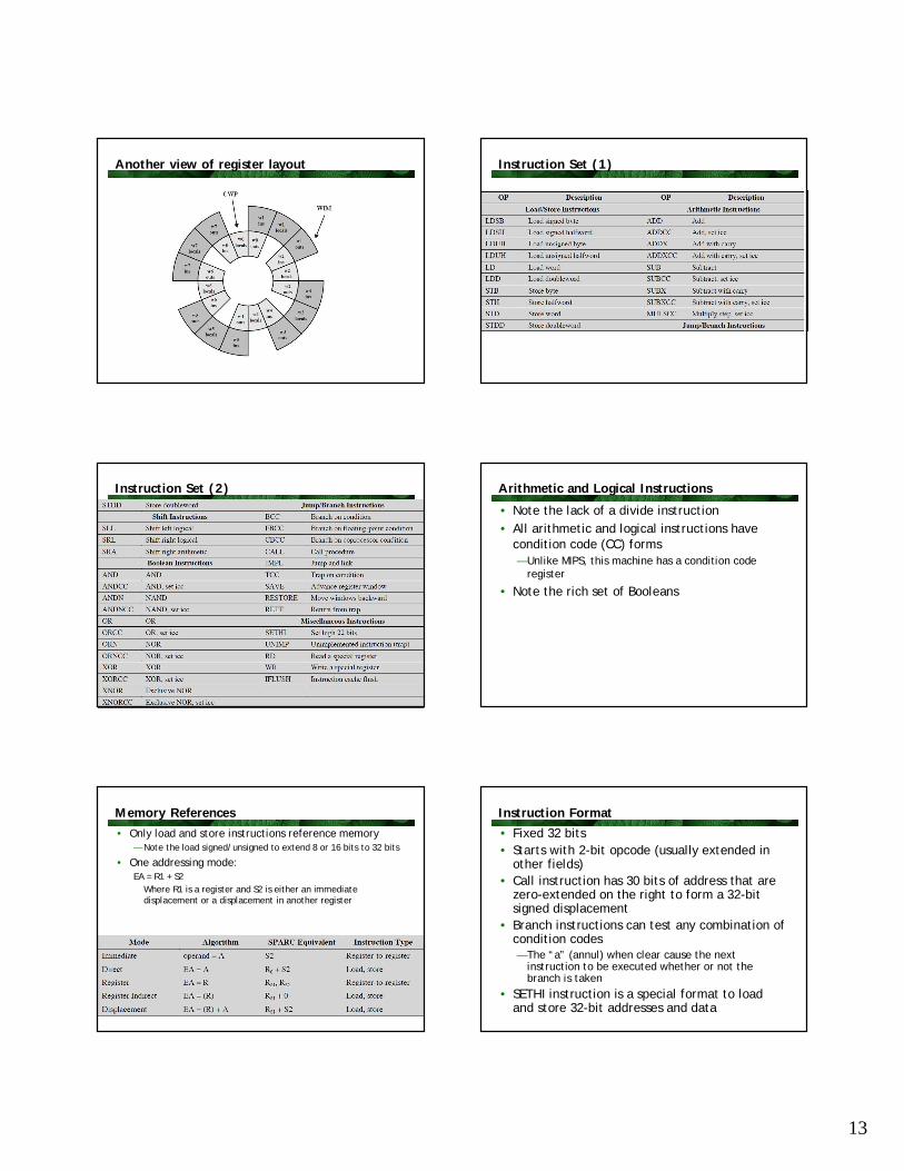
SPARC Registers
• Uses register windows, each with 24 registers• Number of windows ranges from 2 to 32• Each procedure has a set of 32 logical registers
0 through 31— Physical registers 0-7 are global and shared by all
processes / procedures— Logical registers 24-31 are “ins”; shared with with
calling (parent) procedure— Logical registers 8-15 are “outs”; shared with called
(child) procedure— These portions overlap in register windows— Logical registers 16-23 are locals and do not overlap
Procedure calls
• Calling procedures load parameters in the outs registers
• Called procedure sees these as the ins• Processor maintains window state in the
processor status register:— CWP current window pointer— WIM windows invalid mask
• Saving and restoring registers for procedure calls is not normally necessary
• Compiler can be concernd primarily with local optimization
SPARC Instruction Set
• Most instructions have only register operands• Three-address format:
Dest <- Source1 op Source2
• Dest and Source1 are registers• Source2 is either a register or a 13-bit
immediate operand • Register R0 is hardwired 0
Register Layout with three procedures
13
Another view of register layout Instruction Set (1)
Instruction Set (2) Arithmetic and Logical Instructions
• Note the lack of a divide instruction• All arithmetic and logical instructions have
condition code (CC) forms— Unlike MIPS, this machine has a condition code
register
• Note the rich set of Booleans
Memory References• Only load and store instructions reference memory
— Note the load signed/unsigned to extend 8 or 16 bits to 32 bits
• One addressing mode: EA = R1 + S2
Where R1 is a register and S2 is either an immediate displacement or a displacement in another register
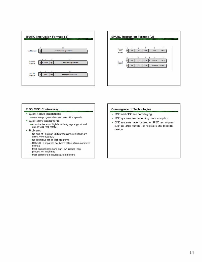
Instruction Format
• Fixed 32 bits• Starts with 2-bit opcode (usually extended in
other fields)• Call instruction has 30 bits of address that are
zero-extended on the right to form a 32-bit signed displacement
• Branch instructions can test any combination of condition codes— The “a” (annul) when clear cause the next
instruction to be executed whether or not the branch is taken
• SETHI instruction is a special format to load and store 32-bit addresses and data
14
SPARC Instruction Formats (1) SPARC Instruction Formats (2)
RISC/CISC Controversy
• Quantitative assessments— compare program sizes and execution speeds
• Qualitative assessments— examine issues of high level language support and
use of VLSI real estate• Problems
— No pair of RISC and CISC processors exists that are directly comparable
— No definitive set of test programs— Difficult to separate hardware effects from compiler
effects— Most comparisons done on “toy” rather than
production machines— Most commercial devices are a mixture
Convergence of Technologies
• RISC and CISC are converging• RISC systems are becoming more complex • CISC systems have focused on RISC techniques
such as large number of registers and pipeline design