computer organization and assembly language lecture 1 & 2 introduction and basics course...
TRANSCRIPT

COMPUTER ORGANIZATION AND ASSEMBLY LANGUAGE
Lecture 1 & 2Introduction and Basics
Course Instructor: Aisha Danish

Lecture Overview
Course Information Marking Scheme Recommended Books Why study Computer Organization? What is a Microcomputer ? Fetch, Decode and Execute Three-Bus System Architecture

Course Information
Name: Computer Organization and Assembly Language
Course Code: CSC-395 Credit Hours: 2+1

Marking Scheme
3 quizzes 10 marks 2 Assignments 5 marks 1 Class Presentation 5 marks 1 Lab Quiz 5 marks 1 Lab Project 5 marks Mid-term Exam 20 marks Final Exam 50 marks

Recommended Books
Computer Organization and Architecture: Designing for Performance, 8/E, William Stallings
Assembly Language for Intel Based Processors, Kip R. Irvine

Why study computer organization and architecture?
Design better programs, including system software such as compilers, operating systems, and device drivers.
Optimize program behavior. Evaluate (benchmark) computer system performance. Understand time, space, and price tradeoffs.
Computer organization Encompasses all physical aspects of computer systems. E.g., circuit design, control signals, memory types. How does a computer work?
Computer architecture Logical aspects of system implementation as seen by the
designer. E.g., instruction sets, instruction formats, data types,
addressing modes. How do I design a computer?
Microcomputer
A microcomputer is an electronic device with a microprocessor as its central processing unit (CPU), a memory, and input/output (I/O) facilities
Most of today’s computer systems are based on a design principle proposed by Dr. John Von Neumann (1946)

Program Concept
Hardwired systems are inflexible General purpose hardware can do
different tasks, given correct control signals
Instead of re-wiring, supply a new set of control signals

What is a program?
A sequence of steps For each step, an arithmetic or logical
operation is done For each operation, a different set of
control signals is needed

Function of Control Unit
For each operation a unique code is provided e.g. ADD, MOVE
A hardware segment accepts the code and issues the control signals
We have a computer!
Components
The Control Unit and the Arithmetic and Logic Unit constitute the Central Processing Unit
Data and instructions need to get into the system and results out Input/output
Temporary storage of code and results is needed Main memory

Computer Components:Top Level View

Instruction Cycle
Two steps: Fetch Execute

Fetch Cycle
Program Counter (PC) holds address of next instruction to fetch
Processor fetches instruction from memory location pointed to by PC
Increment PC Unless told otherwise
Instruction loaded into Instruction Register (IR)
Processor interprets instruction and performs required actions

Execute Cycle
Processor-memory data transfer between CPU and main memory
Processor I/O Data transfer between CPU and I/O module
Data processing Some arithmetic or logical operation on data
Control Alteration of sequence of operations e.g. jump
Combination of above

The Instruction Set
− The job of the Instruction Decoder (ID) is to recognize
and activate appropriate controls in the CPU needed to
execute the instruction.− The list of all instructions recognized by the ID is calledthe instruction set
− Microprocessors are classified based on thespecification of the instruction sets into two categories:(1) Complex Instruction Set Computers (CISC) and(2) Reduced Instruction Set Computers (RISC)

Bus Interface Unit (BIU) andExecution Unit (EU)
Modern CPUs:− Most microprocessors today are designed to allow the fetch
and execute cycles to overlap.
− This is done by dividing the CPU into two units:(1) a Bus Interface Unit (BIU) and(2) an Execution Unit (EU).− The job of the BIU is to fetch instructions from memory and
store them in a special instruction queue.− The EU then fetches instructions from this queue (not from
memory).− Some processors have a pipelined execution unit that
allows the decoding and execution of instructions to overlap.

Buses
There are a number of possible interconnection systems
Single and multiple BUS structures are most common
e.g. Control/Address/Data bus (PC) e.g. Unibus (DEC-PDP)

What is a Bus?
A communication pathway connecting two or more devices
Usually broadcast Often grouped
A number of channels in one bus e.g. 32 bit data bus is 32 separate single bit
channels Power lines may not be shown

Data Bus
Carries data Remember that there is no difference
between “data” and “instruction” at this level
Width is a key determinant of performance 8, 16, 32, 64 bit

Address bus
Identify the source or destination of data e.g. CPU needs to read an instruction
(data) from a given location in memory Bus width determines maximum
memory capacity of system e.g. 8080 has 16 bit address bus giving 64k
address space

Control Bus
Control and timing information Memory read/write signal Interrupt request Clock signals

Three-Bus System Architecture
A bus is a collection of electronic signal lines all dedicated to a particular task
The architecture considered in the previous slides consists of three types of buses: address, data, and control buses

Three-Bus System ArchitectureThe Data Bus:−The data bus consists of internal and external databuses.−The internal data bus connects the internal componentsof the CPU (e.g. Registers, ALU, etc.) to the data I/O pinsof the CPU.− The external data bus connects the data I/O pins of theCPU to the memory and I/O devices (e.g. printer,monitor, etc).−The width of the internal data bus in bits is usually usedto classify a microprocessor (e.g. 8-bit, 16-bit, 32-bimicroprocessors)

Three-Bus System ArchitectureThe Data Bus:−The width of the internal data bus is
usually the same as the external data bust – but not always.
− The 80386 processor has 32-bit internal and 32-bit external data buses.
− The Pentium processor has 32-bit internal data bus and 64-bit external data bus

Three-Bus System ArchitectureThe address Bus:−It is used to identify the memory location or I/O device(also called I/O port) to be accessed by the CPU−The width of this bus in the 80x86 family varies
fromone processor to the other for example: The 8086/8088 processors have 20-bit address bus. The 80286 processor has 24-bit address bus. The 80386/80486/Pentium processors have 32-bit
address bus. The Pentium Pro processor has 36-bit address bus.
Three-Bus System Architecture
The Control Bus:−How can we tell if the address on the address bus is amemory address or an I/O port ?− How can we tell if the memory or I/O access is a read orwrite operation ?− These questions are answered by the control bus--The control bus carries commands from the CPU and returns
status signals from the devices− Each time the processor outputs an address, it alsoactivates one of 4 control signals(1) Memory Read(2) Memory Write(3) I/O Read(4) I/O Write

Instruction Cycle State Diagram

Interrupts
Mechanism by which other modules (e.g. I/O) may interrupt normal sequence of processing
Program e.g. overflow, division by zero
Timer Generated by internal processor timer Used in pre-emptive multi-tasking
I/O from I/O controller
Hardware failure e.g. memory parity error

Interrupt Cycle
Added to instruction cycle Processor checks for interrupt
Indicated by an interrupt signal If no interrupt, fetch next instruction If interrupt pending:
Suspend execution of current program Save context Set PC to start address of interrupt handler routine Process interrupt Restore context and continue interrupted program
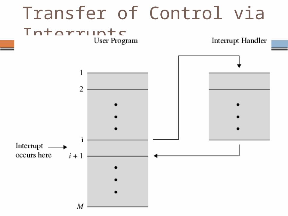
Transfer of Control via Interrupts
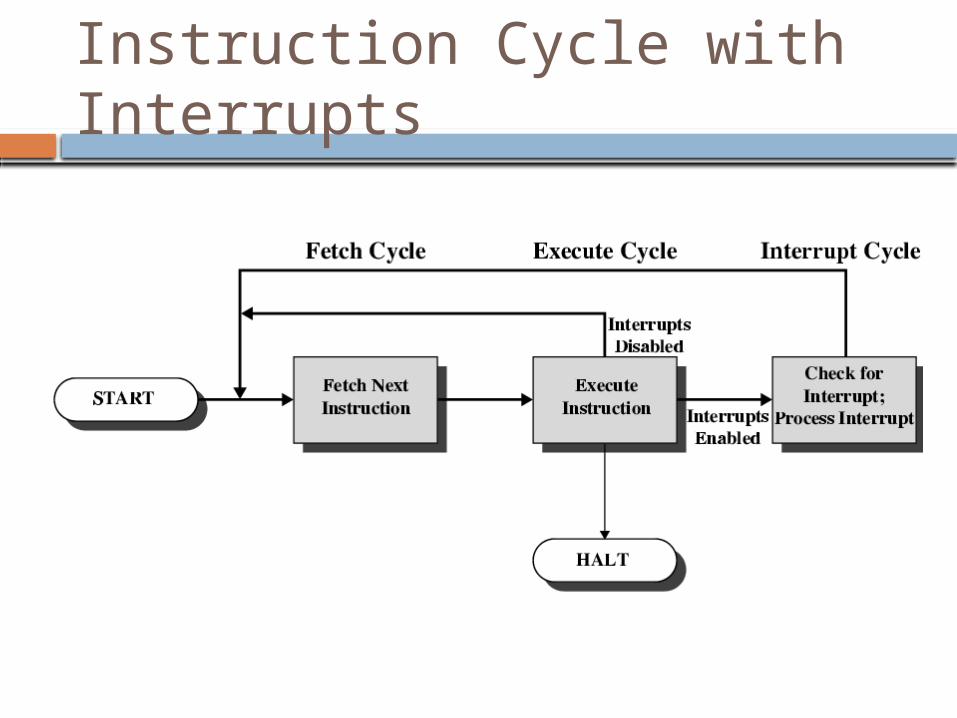
Instruction Cycle with Interrupts

Instruction Cycle (with Interrupts) - State Diagram