computer organization & architecture · pdf filecomputer organization & architecture...
TRANSCRIPT

COMPUTER ORGANIZATION
& ARCHITECTURE
CPU Architecture
Lesson 7
1CSCD211- DEPARTMENT OF COMPUTER SCIENCE, UNIVERSITY OF GHANA
2CSCD211- DEPARTMENT OF COMPUTER SCIENCE, UNIVERSITY OF GHANA
Introduction• Here the focus is on the most complex aspect of ALU and
control unit which are the main components of the processingunit
• There is the need for the Internal CPU bus to transfer databetween the various registers and the ALU
The control unit is the portion of the processor that actuallycauses things to happen. The control unit issues control signals:
• Internal to the processor to move data between registers, tocause ALU to perform a specified function and to regulateother internal operations
• External to the processor to cause data exchange with memoryand I/O modules
3CSCD211- DEPARTMENT OF COMPUTER SCIENCE, UNIVERSITY OF GHANA
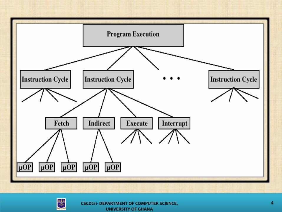
Micro OperationsThe execution of one instruction consists of one or more fetchand one execute cycle
The time or clock for execution of a single instruction is called aninstruction cycle
Each instruction cycle is considered to be made up of smallerunits. Most common smaller units of instruction cycle are:• Fetch• Indirect• Execute• Interrupt
Each smaller cycle involves a series of steps called micro-operations. These micro-operations involve the CPU registers
4CSCD211- DEPARTMENT OF COMPUTER SCIENCE, UNIVERSITY OF GHANA
5CSCD211- DEPARTMENT OF COMPUTER SCIENCE, UNIVERSITY OF GHANA
Micro Operation – Fetch CycleFetch cycle occurs at the beginning of every instruction. There are four main registers that are involved;
• Memory Address Register (MAR)-Connected to address bus-Specifies address for read or write operation
• Memory Buffer Register (MBR)-Connected to data bus-Holds data to write or last data read
• Program Counter (PC)-Holds address of next instruction to be fetched (notconnected to address bus)
• Instruction Register (IR)-Holds last instruction fetched (not connected to data bus)
6CSCD211- DEPARTMENT OF COMPUTER SCIENCE, UNIVERSITY OF GHANA
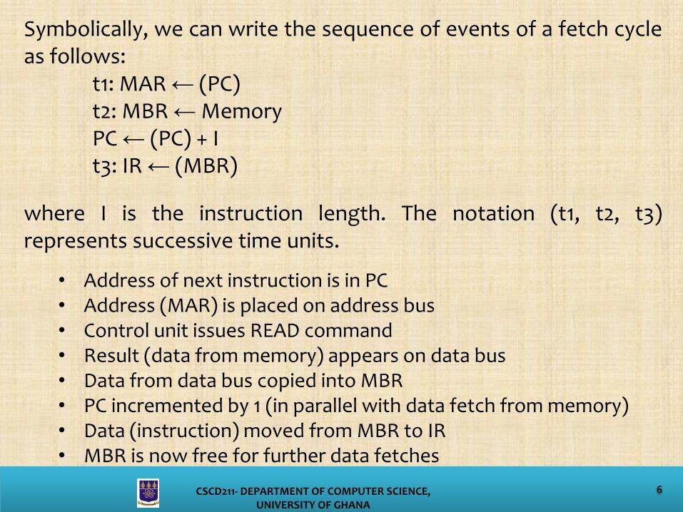
Symbolically, we can write the sequence of events of a fetch cycleas follows:
t1: MAR ← (PC)t2: MBR ← MemoryPC ← (PC) + It3: IR ← (MBR)
where I is the instruction length. The notation (t1, t2, t3)represents successive time units.
• Address of next instruction is in PC• Address (MAR) is placed on address bus• Control unit issues READ command• Result (data from memory) appears on data bus• Data from data bus copied into MBR• PC incremented by 1 (in parallel with data fetch from memory)• Data (instruction) moved from MBR to IR• MBR is now free for further data fetches
7CSCD211- DEPARTMENT OF COMPUTER SCIENCE, UNIVERSITY OF GHANA
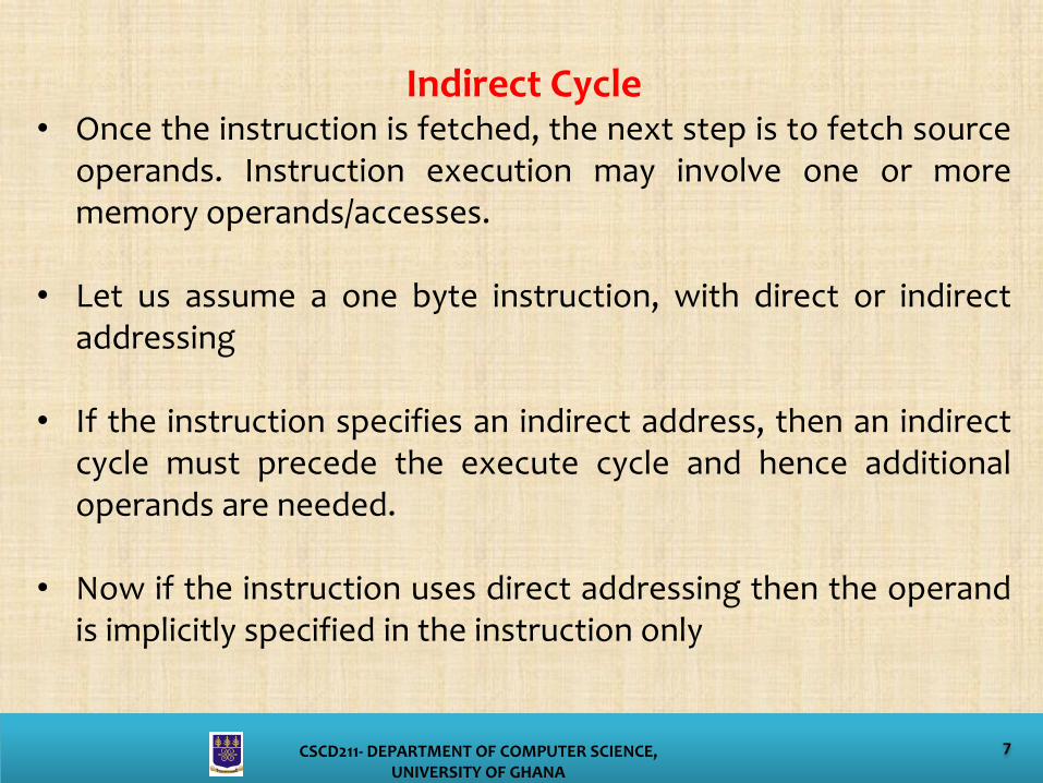
Indirect Cycle• Once the instruction is fetched, the next step is to fetch source
operands. Instruction execution may involve one or morememory operands/accesses.
• Let us assume a one byte instruction, with direct or indirectaddressing
• If the instruction specifies an indirect address, then an indirectcycle must precede the execute cycle and hence additionaloperands are needed.
• Now if the instruction uses direct addressing then the operandis implicitly specified in the instruction only

8CSCD211- DEPARTMENT OF COMPUTER SCIENCE, UNIVERSITY OF GHANA
• The data flow of an indirect cycle consists of the followingmicro operations.
t1: MAR ← (IR(Address))t2: MBR ← Memoryt3: IR(Address) ← (MBR(Address))
• Address field of the instruction is transferred to the MAR.This address is then used to fetch the address of theoperand. Now the address of IR is updated from the MBR,and it contains a direct rather than indirect address
9CSCD211- DEPARTMENT OF COMPUTER SCIENCE, UNIVERSITY OF GHANA
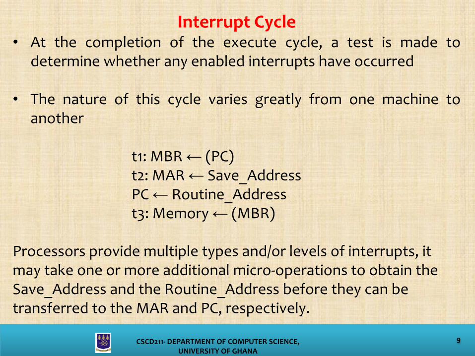
Interrupt Cycle• At the completion of the execute cycle, a test is made to
determine whether any enabled interrupts have occurred
• The nature of this cycle varies greatly from one machine toanother
t1: MBR ← (PC)t2: MAR ← Save_AddressPC ← Routine_Addresst3: Memory ← (MBR)
Processors provide multiple types and/or levels of interrupts, it may take one or more additional micro-operations to obtain the Save_Address and the Routine_Address before they can be transferred to the MAR and PC, respectively.
10CSCD211- DEPARTMENT OF COMPUTER SCIENCE, UNIVERSITY OF GHANA
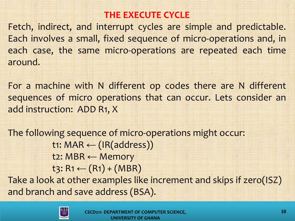
THE EXECUTE CYCLEFetch, indirect, and interrupt cycles are simple and predictable.Each involves a small, fixed sequence of micro-operations and, ineach case, the same micro-operations are repeated each timearound.
For a machine with N different op codes there are N differentsequences of micro operations that can occur. Lets consider anadd instruction: ADD R1, X
The following sequence of micro-operations might occur:t1: MAR ← (IR(address))t2: MBR ← Memoryt3: R1 ← (R1) + (MBR)
Take a look at other examples like increment and skips if zero(ISZ) and branch and save address (BSA).
11CSCD211- DEPARTMENT OF COMPUTER SCIENCE, UNIVERSITY OF GHANA
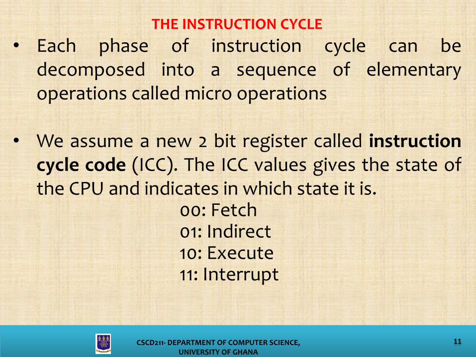
THE INSTRUCTION CYCLE
• Each phase of instruction cycle can bedecomposed into a sequence of elementaryoperations called micro operations
• We assume a new 2 bit register called instructioncycle code (ICC). The ICC values gives the state ofthe CPU and indicates in which state it is.
00: Fetch01: Indirect10: Execute11: Interrupt
12CSCD211- DEPARTMENT OF COMPUTER SCIENCE, UNIVERSITY OF GHANA
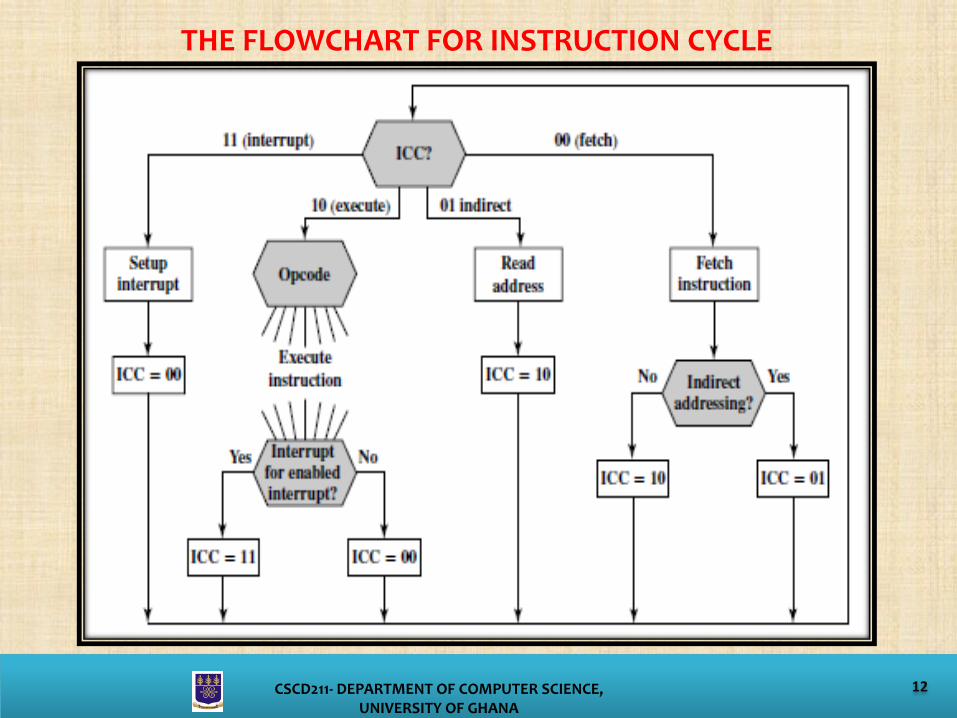
THE FLOWCHART FOR INSTRUCTION CYCLE

13CSCD211- DEPARTMENT OF COMPUTER SCIENCE, UNIVERSITY OF GHANA
FUNCTIONAL REQUIREMENTS• The functional requirements of control unit are those
functions that the control unit must perform.
• There are three processes that lead to characterizingthe control unit.
• Define the basic elements of the processor• Describe the micro-operations that the
processor performs• Determine the functions that the control unit
must perform to cause the micro-operations tobe performed.
14CSCD211- DEPARTMENT OF COMPUTER SCIENCE, UNIVERSITY OF GHANA
TYPES OF MICRO OPERATIONSThe execution of a program consists of operations involving CPU elementsAll micro instructions fall into one of the following categories:
• Transfer data between registers• Transfer data from register to external• Transfer data from external to register• Perform arithmetic or logical ops
FUNCTIONS OF CONTROL UNITThe control unit perform two tasks:• Sequencing: The control unit causes the CPU to step through a
series of micro-operations in proper sequence based on theprogram being executed.
• Execution: The control unit causes each micro-operation to beperformed.
15CSCD211- DEPARTMENT OF COMPUTER SCIENCE, UNIVERSITY OF GHANA
THE CONTROL SIGNALS• For a full performance of the control unit, it must have inputs
and outputs (external specifications) and must have logic(internal)
Some possible inputs include;Clock: It uses clock to maintain the timings. Also referred to asprocessor clock time or clock cycle time.
IR : Uses Op-code for current instruction to determines whichmicro-instructions are performed
Flags: Determine the status of the CPU and outcome of previousALU operations
Control bus: This provides signals to the control unit, such asinterrupt signals and acknowledgements.

16CSCD211- DEPARTMENT OF COMPUTER SCIENCE, UNIVERSITY OF GHANA
MODEL OF CONTROL UNIT

17CSCD211- DEPARTMENT OF COMPUTER SCIENCE, UNIVERSITY OF GHANA
Control Signals – OutputControl signals within CPU: There are two types
• Signals that cause data to be moved from oneregister to another.
• Signals that activate specific ALU functions
Control signals to control bus: There are two types• signals to memory• signals to I/O modules
18CSCD211- DEPARTMENT OF COMPUTER SCIENCE, UNIVERSITY OF GHANA
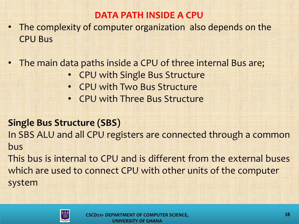
DATA PATH INSIDE A CPU• The complexity of computer organization also depends on the
CPU Bus
• The main data paths inside a CPU of three internal Bus are;• CPU with Single Bus Structure• CPU with Two Bus Structure• CPU with Three Bus Structure
Single Bus Structure (SBS)In SBS ALU and all CPU registers are connected through a commonbusThis bus is internal to CPU and is different from the external buseswhich are used to connect CPU with other units of the computersystem

19CSCD211- DEPARTMENT OF COMPUTER SCIENCE, UNIVERSITY OF GHANA
Single Bus Structure of Data Path Inside CPU
20CSCD211- DEPARTMENT OF COMPUTER SCIENCE, UNIVERSITY OF GHANA
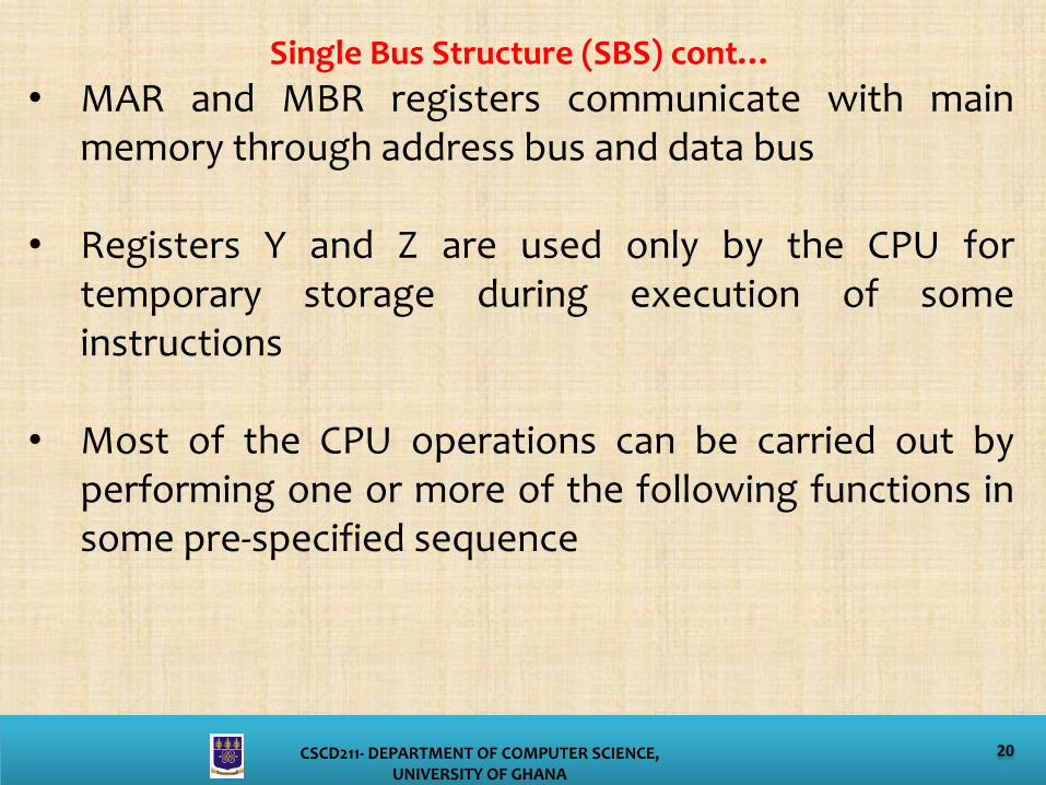
Single Bus Structure (SBS) cont…
• MAR and MBR registers communicate with mainmemory through address bus and data bus
• Registers Y and Z are used only by the CPU fortemporary storage during execution of someinstructions
• Most of the CPU operations can be carried out byperforming one or more of the following functions insome pre-specified sequence
21CSCD211- DEPARTMENT OF COMPUTER SCIENCE, UNIVERSITY OF GHANA
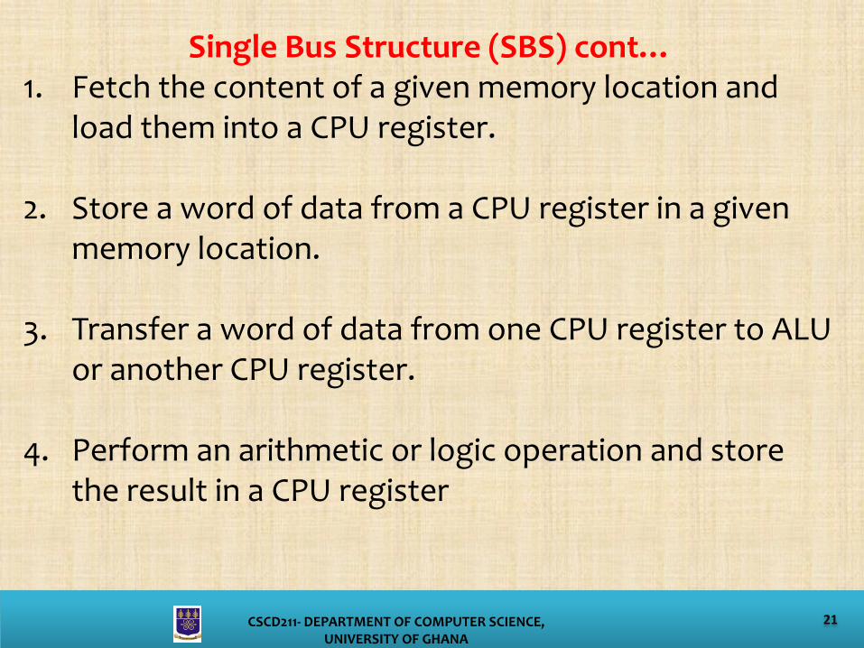
Single Bus Structure (SBS) cont…1. Fetch the content of a given memory location and
load them into a CPU register.
2. Store a word of data from a CPU register in a given memory location.
3. Transfer a word of data from one CPU register to ALU or another CPU register.
4. Perform an arithmetic or logic operation and store the result in a CPU register

22CSCD211- DEPARTMENT OF COMPUTER SCIENCE, UNIVERSITY OF GHANA
Fetching a word from the memoryConsider an example, assume that the address of the memorylocation to be accessed is in register R0 and data is to beloaded into register R1.
The following sequence of operations are used to achievethis.1. MAR [R0]2. Read3. Wait for MFC signal4. R1 [MBR]
The transfer mechanism where one device initiates thetransfer and waits until the other device responds is calledasynchronous transfer
23CSCD211- DEPARTMENT OF COMPUTER SCIENCE, UNIVERSITY OF GHANA
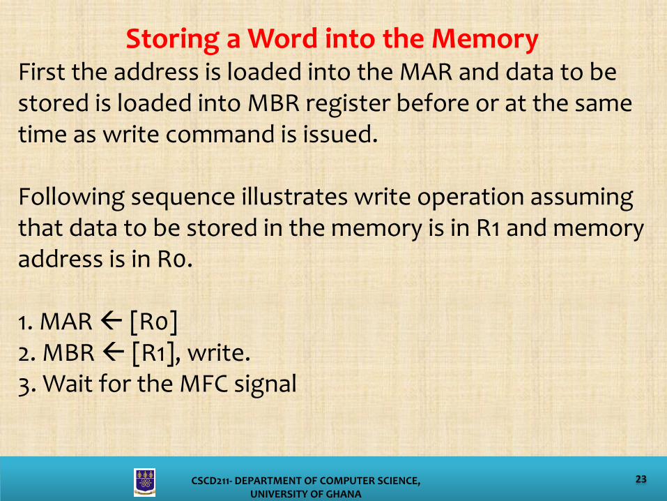
Storing a Word into the MemoryFirst the address is loaded into the MAR and data to be stored is loaded into MBR register before or at the same time as write command is issued.
Following sequence illustrates write operation assuming that data to be stored in the memory is in R1 and memory address is in R0.
1. MAR [R0]2. MBR [R1], write.3. Wait for the MFC signal
24CSCD211- DEPARTMENT OF COMPUTER SCIENCE, UNIVERSITY OF GHANA
Two Bus StructureAn alternative arrangement for the single bus organization is the two bus structureall the register outputs are connected to bus A, and all register inputs are connected to bus B
The bus tie G connects two buses together
When G is enabled, it transfers data onbus A to bus B and when it is disabled two buses are electricallydisconnected. The temporary register Z is not required in this organizationbecause, when bus tie G is disabled, the output of ALU can be transferreddirectly to the destination register.

25CSCD211- DEPARTMENT OF COMPUTER SCIENCE, UNIVERSITY OF GHANA
Two Bus Structure
26CSCD211- DEPARTMENT OF COMPUTER SCIENCE, UNIVERSITY OF GHANA
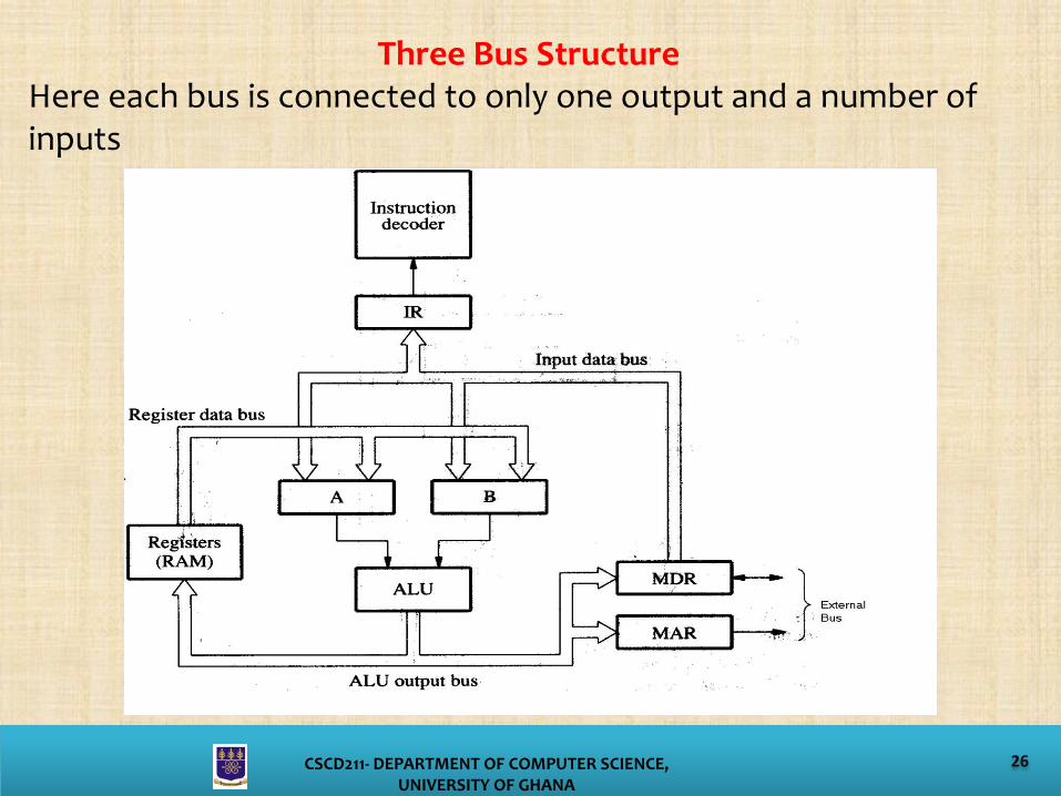
Three Bus StructureHere each bus is connected to only one output and a number of inputs
27CSCD211- DEPARTMENT OF COMPUTER SCIENCE, UNIVERSITY OF GHANA
Three Bus Structure cont…Two registers A and B are provided, which can be loaded fromeither the input data bus or the register data bus.
Three data transfers can take place at the same time.Componentsconnected to each bus are less when compared to two busstructure. Hence data transfer will be faster in this case.
BRANCHINGBranching is achieved by replacing the current contents of thePC by the branch address. Branch address is obtained by addingan offset X given in the address field of branch instruction, tothe current value of PC

28CSCD211- DEPARTMENT OF COMPUTER SCIENCE, UNIVERSITY OF GHANA
Sequencing of Control Signals• The functional requirement of control unit is
sequencing and then execution.
• Sequencing is very necessary to execute theinstructions. That is the CPU must generate thecontrol signals in the proper sequence.
Two techniques used to solve the problem of sequencingare;1. Hardwired control2. Micro programmed control

29CSCD211- DEPARTMENT OF COMPUTER SCIENCE, UNIVERSITY OF GHANA
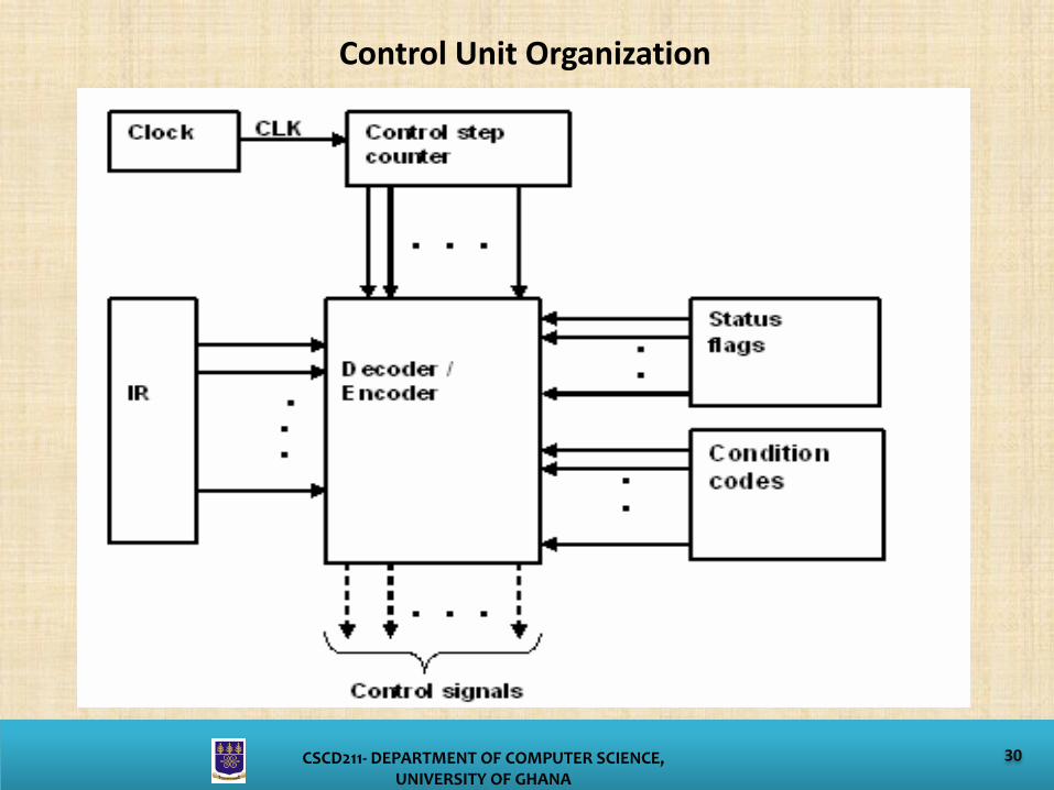
Hardwired Control UnitsIn a hardwired implementation, the control unit is essentially a combinatorial circuit. Its input logic signals are transformed into a set of output logic signals, which are the control signals.
The required control signals are determined based on the following information.• Contents of the control counter• Contents of the instruction register• Contents of the control codes and other status flags
30CSCD211- DEPARTMENT OF COMPUTER SCIENCE, UNIVERSITY OF GHANA
Control Unit Organization
31CSCD211- DEPARTMENT OF COMPUTER SCIENCE, UNIVERSITY OF GHANA
Problems with Hardwired Designs• Complex sequencing & micro-operation logic• Difficult to design and test• Inflexible design• Difficult to add new instructions

32CSCD211- DEPARTMENT OF COMPUTER SCIENCE, UNIVERSITY OF GHANA
Micro-programmed Control UnitAn alternative approach which is quite common is MicroProgrammed Control unit. The control signals and each microoperation is described using a programming language called microprogramming language.
Control Word (CW): A word whose individual bits represent thecontrol signals.Micro routine: A sequence of control words corresponding to thecontrol sequence of a machine instruction constitutes the microroutine for that instruction.Micro program Memory: it is a special memory in which the microroutines corresponding to the instruction set of a computer arestored.Micro program Counter ( PC): This is used to read the control wordssequentially from the micro program memory

33CSCD211- DEPARTMENT OF COMPUTER SCIENCE, UNIVERSITY OF GHANA
Microprogrammed Control Unit
34CSCD211- DEPARTMENT OF COMPUTER SCIENCE, UNIVERSITY OF GHANA
Basic ConceptWhen a new instruction is loaded into the IR, the starting addressis loaded into the PC from the starting address generator block.
Automatically, the PC is incremented by the clock, causingsuccessive microinstructions to be read from the memory. Thus,the control signals are loaded into various parts of the CPU in thecorrect sequence
Another important function of the control unit is to check for thestatus of the condition codes or status flags while branching.

35CSCD211- DEPARTMENT OF COMPUTER SCIENCE, UNIVERSITY OF GHANA
Control Unit to Enable Conditional Branching in the MicroprogramIn the case of hardwired control, this situation is handled by including an appropriate logic function in the encoder circuitry whereas in the case of micro programmed control, the microinstruction set is expanded to include some conditional branchmicroinstructions
36CSCD211- DEPARTMENT OF COMPUTER SCIENCE, UNIVERSITY OF GHANA
Advantages and Disadvantages• The principal advantage of the use of microprogramming to
implement a control unit is that it simplifies the design of thecontrol unit.
• It is both cheaper and less error prone to implement.• A hardwired control unit must contain complex logic for
sequencing through the many micro-operations of the instructioncycle.
• On the other hand, the decoders and sequencing logic unit of amicro-programmed control unit are very simple pieces of logic.
• The principal disadvantage of a micro-programmed unit is that itwill be somewhat slower than a hardwired unit of comparabletechnology. Despite this, microprogramming is the dominanttechnique for implementing control units in pure CISCarchitectures, due to its ease of implementation.

37CSCD211- DEPARTMENT OF COMPUTER SCIENCE, UNIVERSITY OF GHANA
Two Bus Structure