computer resource management system
DESCRIPTION
Computer Resource Management SystemTRANSCRIPT

ABSTRACT
ABSTRACT
Computer Resource Management System (CRMS) is a total management and
informative system, which provides the up-to date information of all the computer
resources in the company. CRMS helps the company to overcome it’s difficulty in
tracking the resources of the company by presenting the customized reports, which
helps in effective and timely utilization of the hardware and the software resources.
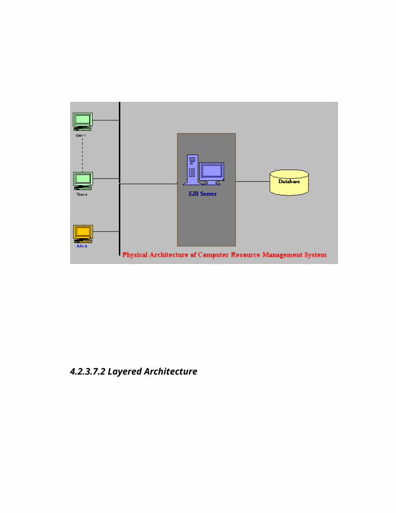
CRMS is a web-based application using the three-tire architecture. The ability to
handle the multi-user environment and the maintaining the highest security for the
access are some of the features of this application.
CRMS uses Oracle 8i as the back end for the database and uses all its features offered
in the web based technology for its transactions.
CRMS uses the Enterprise Java Beans as the middle ware for its business logic
implementation. It uses the Weblogic Server, Version 5.1 provided by the BEA
Solutions.
INTORDUCTION
INTORDUCTION:
Computer Resource Management System (CRMS) is a total management and
informative system, which provides the up-to date information of all the computer
resources in the company. CRMS helps the company to overcome it’s difficulty in
tracking the resources of the company by presenting the customized reports, which
helps in effective and timely utilization of the hardware and the software resources.
Computer Resource Management System uses the Enterprise JavaBeans Version 1.1,
it’s the component model for the enterprise applications. Enterprise JavaBeans
combines server-side components with distributed object technologies such as Java
RMI to greatly simplify the task of application development. The EJB automatically
takes into account many of the requirements of business systems: security, resource
pooling, persistence, concurrency and transactional integrity.
One of java’s most important features is platform independence. Since it was released,
Java has been marketed as “write once, run anywhere”. Enterprise JavaBeans is not
only platform independent –it’s also implementation independent. Its like JDBC API
runs on a Windows machine or on a Unix machine, it can access any vendor’s
relational database that has a JDBC driver. Ideally, an Enterprise JavaBeans
component, an enterprise bean, can run in any application server that implements the
Enterprise JavaBeans (EJB) specification. That is we can develop and deploy EJB
business system in one server, such as BEA’s Weblogic and later move it to a different
EJB server, such as IBM’s WebSphere or Gemstone/J. Implementation independence
means that a business components are not dependent on the brand of server.
Computer Resource Management System uses Oracle 8i as the back-end RDBMS.
Oracle 8i is actually a fully Internet supported database system. Oracle 8i perfectly
handles the ACID Transactions. A transaction is the execution of a unit-of-work that
accesses one or more shared resources, usually databases. A unit-of-work is a set of
activities that relate to each other and must be completed together. The ACID
properties are nothing but (Atomic Consistent Isolated Durable) properties
A transaction to be atomic, it must execute completely or not at all. Consistency refers
to the integrity of the underlying data store, consistency is ensured by seeing that a
transaction is atomic, isolated and durable. Isolated refers to allowing a transaction to
execute without interference from other processes or transactions, i.e., the data that a
transaction accesses can not be affected by any other part of the system until the
transaction or unit-of work is completed. Durability means that all the data changes
made during the course of a transaction must be written to some type of physical
storage before the transaction is successfully completed. This ensures that the changes
are not lost if the system crashes. And apart from handling the ACID properties
Oracle 8i has higher security level and web compatibility features.
The computer resource management system mainly consists the following :
1. Components
2. Computers
3. Bin
4. Recycle Bin
5. Status
6. Search / View
1. Components :
Whatever the component that is either software or hardware will be assigned a
unique number and entered into the shelf. Whatever goes out will be deducted from
the shelf and must be entered either to bin, recycle bin or to a computer. For every
component appropriate entry should be made.
2. Computers :
Computers will be assembled using the shelf parts. Every computer should be
given a unique number. The details of the computer will be entered including its
hardware and software profiles with their parts. The computers may be servers,
standalone’s and clients etc.
3. Bin :
The damaged components, which are not repairable or replaceable, will be sent
to this bin.
4. Recycle Bin :
The repairable and replaceable parts will be kept here. A time report is given
like when a part is submitted for repairs or replacement and expected back time and
able to give warnings of delays etc.
5. Status :
The status gives the statistics of the shelf, bin, recycle bin, computers. The
status gives the present position of the component where it is situated in the
organization. Basing on the status the components are used in different transactions.
6. Search / View :
The users can search or view the information of different resources based on
their unique number given to them.
PROBLEM DESCRIPTION
PROBLEM DESCRIPTION
As of now the resource management in Laila Infotech is done
manually. If an employee intends to know the information regarding the resources
pertaining to computers or components and their present and accurate information in
the organization, as of now it is being done manually which consumes a great bit of
manpower and the process is time consuming. The problem of maintaining the bulk
database can be solved by atomizing the resources in the organization, which can be of
great help to all the administrators, employee and the management members.
Some of the frequent occurring problems in the present manual system are as follows:
Finding the current status or position of a component in the organization is a
time-consuming process.
The Manager has to wait for the manual reports from the development dept. to
know the current status of the resources.
In the present system there is no security for the details of the resources as any
user who is not authenticated to view the records may see them.
To view the details of a computer and to know what are the components that
are assigned to it, can be done only by a manual checking of that computer for
the hardware and software components is a tedious process.
The users of the organization require various reports to be generated in an easy
format, which is not so easy when done manually.
The Manager may get problems in finding out a user details in hundreds of
records.
NEED FOR COMPUTERISATION:
Maintaining the information regarding all employees, components and
computers at single or multiple locations give raise to many problems like :
Difficulty in retrieval of data in desired manner.
Checking the uniqueness wherever it is required.
Availability of information in this manner is subjected to
damage.
Providing security is also difficult.
One way to overcome all these difficulties is so store all the information in the
computer. The computerization helps the users a lot. The user can get information in
desired manner. Data retrieval is also easy and fast. This also restricts the users to
enter invalid data and reduces the burden on the user.
BENEFITS OF COMPUTERIZATION OF PROPOSED SYSTEM:
A computer based information system is usually needed for the following
purposes.
Greater Processing Speed:
Using computers inherent ability to calculate, sort, retrieve data with greater
speed than that of the human doing we can get results in less time. Visual Basic
guaranties for the faster query processing thus we are satisfied with Visual Basic itself
supporting in this direction.
Better Accuracy and Improved Consistency:
The computer carries out computing steps including arithmetic accurately and
consistently from which really human is escaped which yields more fatigue and
boredom.
Cost Reduction:
Using computerization we can do the required operations with lower cost than
any other methods. Hence by computerization we can reduce the cost drastically.
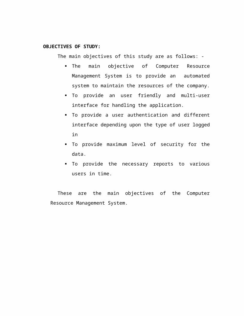
OBJECTIVES OF STUDY:
The main objectives of this study are as follows: -
The main objective of Computer Resource Management System is to
provide an automated system to maintain the resources of the
company.
To provide an user friendly and multi-user interface for handling the
application.
To provide a user authentication and different interface depending upon
the type of user logged in
To provide maximum level of security for the data.
To provide the necessary reports to various users in time.
These are the main objectives of the Computer Resource Management System.
SYSTEM ANALYSIS
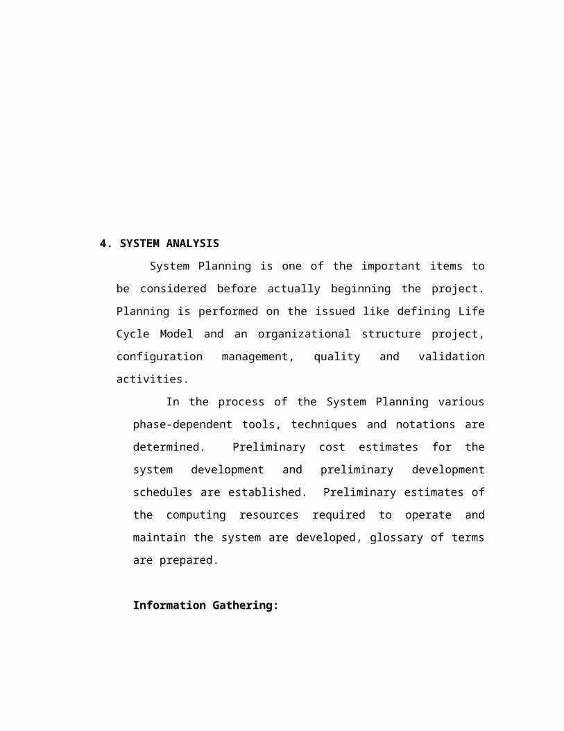
4. SYSTEM ANALYSIS
System Planning is one of the important items to be considered before
actually beginning the project. Planning is performed on the issued like defining
Life Cycle Model and an organizational structure project, configuration
management, quality and validation activities.
In the process of the System Planning various phase-dependent tools,
techniques and notations are determined. Preliminary cost estimates for the
system development and preliminary development schedules are established.
Preliminary estimates of the computing resources required to operate and
maintain the system are developed, glossary of terms are prepared.
Information Gathering:
Information relevant to the “Computer Resource Management System”
of Laila Infotech is collected from the Laila Infotech Limited and the finance
department of the company. The information regarding company activities is
gathered from the company’s website www.lailainfotech.com.
Feasibility Study:
An initial investigation culminates in a proposal that determines
whether an alternative system is feasible than the present candidate system. To
do feasible study we have to do the Economic, Technical, Behavioral feasible
studies.
1.Economic Feasibility: -
It is the most frequently used method for evaluating the effectiveness of
a system. It is also called as cost/benefit analysis.
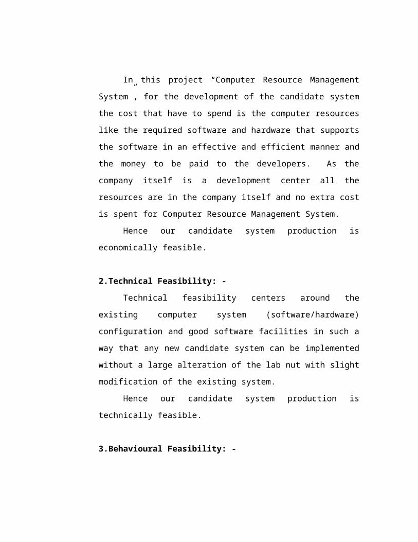
In this project “Computer Resource Management System”, for the
development of the candidate system the cost that have to spend is the
computer resources like the required software and hardware that supports the
software in an effective and efficient manner and the money to be paid to the
developers. As the company itself is a development center all the resources are
in the company itself and no extra cost is spent for Computer Resource
Management System.
Hence our candidate system production is economically feasible.
2.Technical Feasibility: -
Technical feasibility centers around the existing computer system
(software/hardware) configuration and good software facilities in such a way
that any new candidate system can be implemented without a large alteration
of the lab nut with slight modification of the existing system.
Hence our candidate system production is technically feasible.
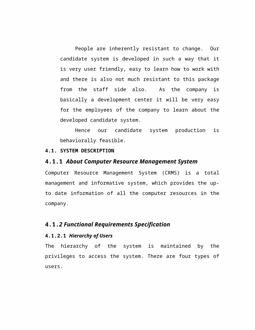
3.Behavioural Feasibility: -
People are inherently resistant to change. Our candidate system is
developed in such a way that it is very user friendly, easy to learn how to work
with and there is also not much resistant to this package from the staff side
also. As the company is basically a development center it will be very easy for
the employees of the company to learn about the developed candidate system.
Hence our candidate system production is behaviorally feasible.
4.1. SYSTEM DESCRIPTION
4.1.1 About Computer Resource Management System
Computer Resource Management System (CRMS) is a total management and
informative system, which provides the up-to date information of all the computer
resources in the company.
4.1.2 Functional Requirements Specification
4.1.2.1 Hierarchy of Users
The hierarchy of the system is maintained by the privileges to access the system.
There are four types of users.
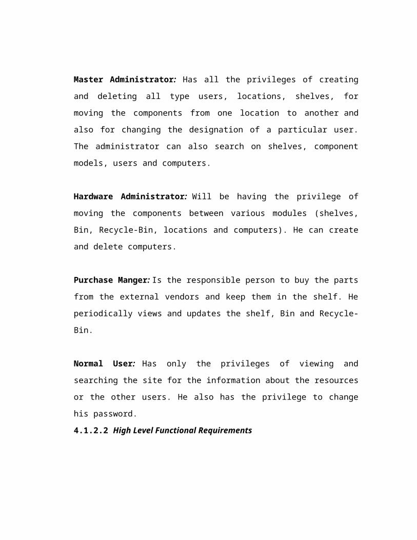
Master Administrator: Has all the privileges of creating and deleting all type users,
locations, shelves, for moving the components from one location to another and also
for changing the designation of a particular user. The administrator can also search on
shelves, component models, users and computers.
Hardware Administrator: Will be having the privilege of moving the components
between various modules (shelves, Bin, Recycle-Bin, locations and computers). He
can create and delete computers.
Purchase Manger: Is the responsible person to buy the parts from the external
vendors and keep them in the shelf. He periodically views and updates the shelf, Bin
and Recycle-Bin.
Normal User: Has only the privileges of viewing and searching the site for the
information about the resources or the other users. He also has the privilege to change
his password.

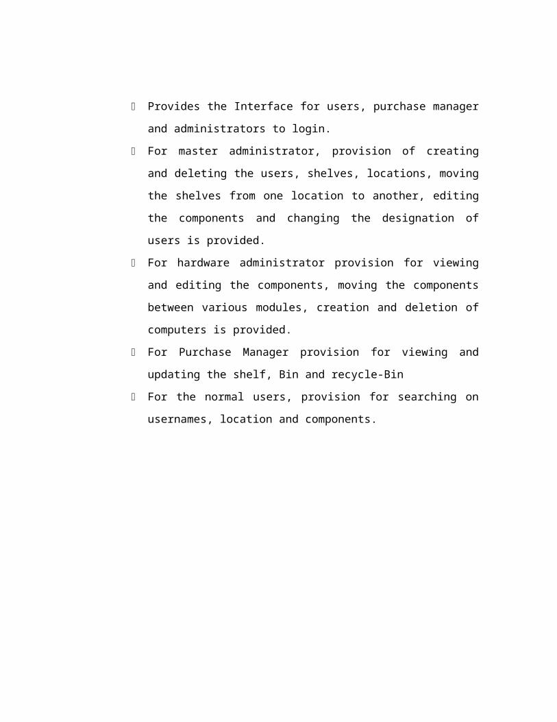
4.1.2.2 High Level Functional Requirements
Provides the Interface for users, purchase manager and administrators to
login.
For master administrator, provision of creating and deleting the users,
shelves, locations, moving the shelves from one location to another, editing
the components and changing the designation of users is provided.
For hardware administrator provision for viewing and editing the
components, moving the components between various modules, creation
and deletion of computers is provided.
For Purchase Manager provision for viewing and updating the shelf, Bin
and recycle-Bin
For the normal users, provision for searching on usernames, location and
components.

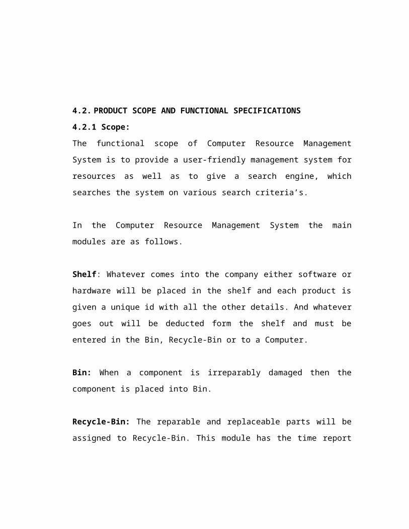
4.2. PRODUCT SCOPE AND FUNCTIONAL SPECIFICATIONS
4.2.1 Scope:
The functional scope of Computer Resource Management System is to provide a user-
friendly management system for resources as well as to give a search engine, which
searches the system on various search criteria’s.
In the Computer Resource Management System the main modules are as follows.
Shelf: Whatever comes into the company either software or hardware will be placed in
the shelf and each product is given a unique id with all the other details. And whatever
goes out will be deducted form the shelf and must be entered in the Bin, Recycle-Bin
or to a Computer.
Bin: When a component is irreparably damaged then the component is placed into
Bin.
Recycle-Bin: The reparable and replaceable parts will be assigned to Recycle-Bin.
This module has the time report like when a part is submitted and what is the expected
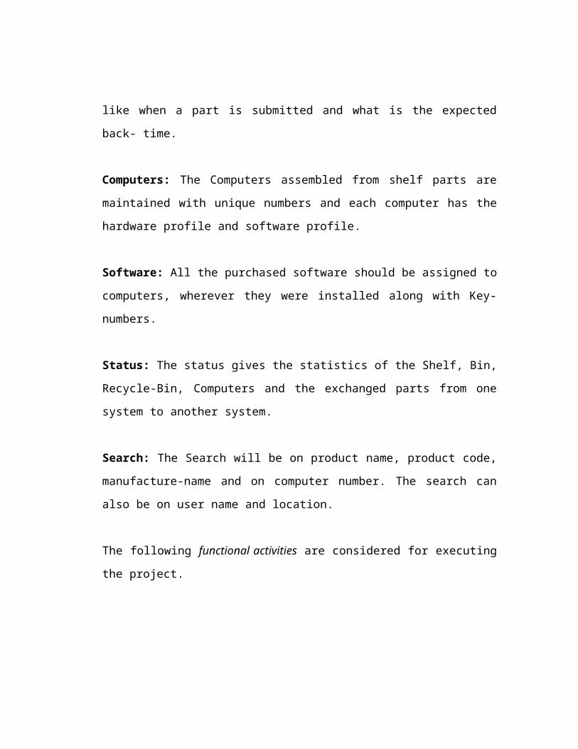
back- time.
Computers: The Computers assembled from shelf parts are maintained with unique
numbers and each computer has the hardware profile and software profile.
Software: All the purchased software should be assigned to computers, wherever they
were installed along with Key-numbers.
Status: The status gives the statistics of the Shelf, Bin, Recycle-Bin, Computers and
the exchanged parts from one system to another system.
Search: The Search will be on product name, product code, manufacture-name and on
computer number. The search can also be on user name and location.
The following functional activities are considered for executing the project.
The normal user will be created by the master administrator with the user-
id and password. The user will have the privilege to change the password
and the user can do the search operation, component wise, location wise
and user wise.
Purchase manager will update the shelf, Bin and Recycle-Bin after taking
the necessary action.
The hardware administrator assembles various parts and updates the shelf,
computers, Bin, software and Recycle-Bin.
The master administrator apart from doing all the activities of other users,
creates and deletes a user, shelf, location, editing the components,
assigning the components to a shelf and moving the shelves form one
location to other besides having the privilege to change the designation of
the users.

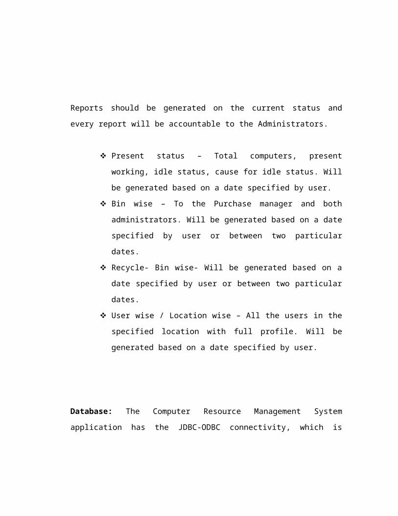
Reports should be generated on the current status and every report will be accountable
to the Administrators.
Present status – Total computers, present working, idle status, cause for
idle status. Will be generated based on a date specified by user.
Bin wise – To the Purchase manager and both administrators. Will be
generated based on a date specified by user or between two particular
dates.
Recycle- Bin wise- Will be generated based on a date specified by user or
between two particular dates.
User wise / Location wise – All the users in the specified location with
full profile. Will be generated based on a date specified by user.
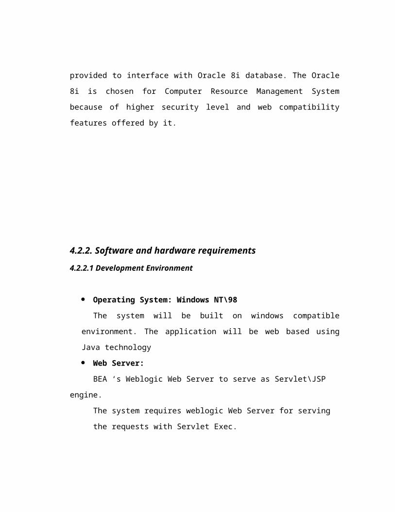
Database: The Computer Resource Management System application has the JDBC-
ODBC connectivity, which is provided to interface with Oracle 8i database. The
Oracle 8i is chosen for Computer Resource Management System because of higher
security level and web compatibility features offered by it.
4.2.2. Software and hardware requirements
4.2.2.1 Development Environment
Operating System: Windows NT\98
The system will be built on windows compatible environment. The application
will be web based using Java technology
Web Server:
BEA ‘s Weblogic Web Server to serve as Servlet\JSP engine.
The system requires weblogic Web Server for serving the requests with Servlet
Exec.
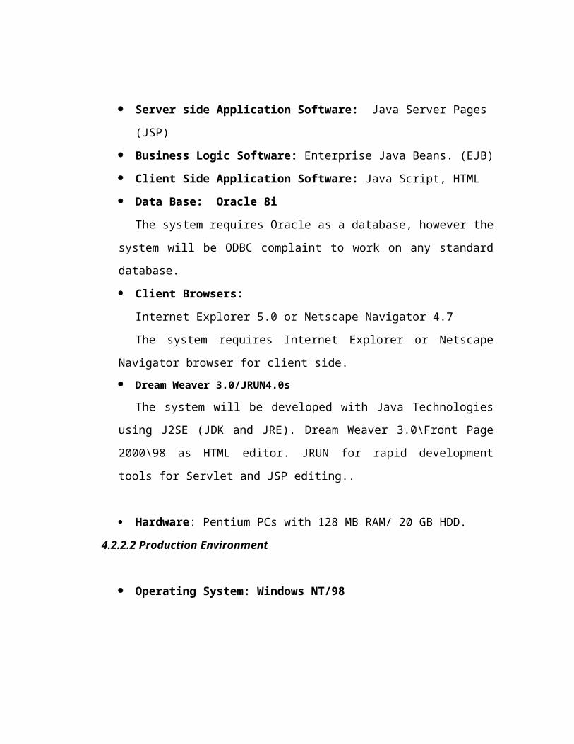
Server side Application Software: Java Server Pages (JSP)
Business Logic Software: Enterprise Java Beans. (EJB)
Client Side Application Software: Java Script, HTML
Data Base: Oracle 8i
The system requires Oracle as a database, however the system will be ODBC
complaint to work on any standard database.
Client Browsers:
Internet Explorer 5.0 or Netscape Navigator 4.7
The system requires Internet Explorer or Netscape Navigator browser for client
side.
Dream Weaver 3.0/JRUN4.0s
The system will be developed with Java Technologies using J2SE (JDK and
JRE). Dream Weaver 3.0\Front Page 2000\98 as HTML editor. JRUN for rapid
development tools for Servlet and JSP editing..
Hardware: Pentium PCs with 128 MB RAM/ 20 GB HDD.
4.2.2.2 Production Environment
Operating System: Windows NT/98
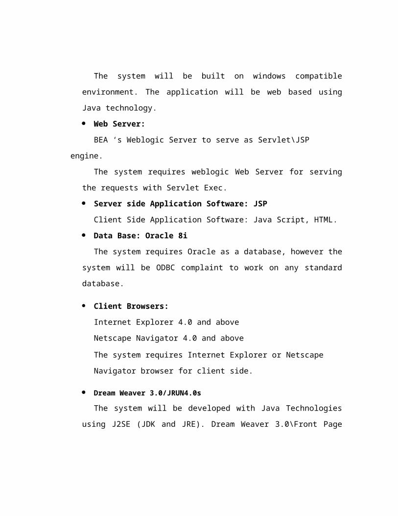
The system will be built on windows compatible environment. The application
will be web based using Java technology.
Web Server:
BEA ‘s Weblogic Server to serve as Servlet\JSP engine.
The system requires weblogic Web Server for serving the requests with Servlet
Exec.
Server side Application Software: JSP
Client Side Application Software: Java Script, HTML.
Data Base: Oracle 8i
The system requires Oracle as a database, however the system will be ODBC
complaint to work on any standard database.
Client Browsers:
Internet Explorer 4.0 and above
Netscape Navigator 4.0 and above
The system requires Internet Explorer or Netscape Navigator browser for client
side.
Dream Weaver 3.0/JRUN4.0s
The system will be developed with Java Technologies using J2SE (JDK and
JRE). Dream Weaver 3.0\Front Page 2000\98 as HTML editor. JRUN for rapid
development tools for Servlet and JSP editing..
Hardware: Pentium PCs with 128 MB RAM/ 20 GB HDD.
4.2.3. Functional Specifications
4.2.3.1. Normal user Setup:
An Interface will be provided for user to login. The user can
login into the system by entering a valid userID and password with the
location.
Provision will be made for changing the password.
A provision will be made by which the user can search for the other
users, computers and components.
4.2.3.2 Purchase Manager Setup:
An interface for viewing the shelves, Bin and Recycle- Bin will be
provided.
An interface for editing the shelves, Bin and Recycle-Bin will be
provided.
4.2.3.3. Hardware Administrator Setup:
The Hardware administrator will be provided with the following
interfaces.
An interface for Creation and deletion of Normal users, computers,
editing the component models.
An interface to view all the users, shelves with components,
locations, display of component model and computers.
Interface for assigning components to a computer from the shelf.
Interface for moving components between Bin, recycle-Bin,
computers and shelf unassigned.
4.2.3.4. Master Administrator Setup:
Apart from doing all the activities of Hardware Administrator,
master administrator has the following additional interfaces.
An interface for creation and deletion of Purchase managers,
Hardware Administrators and other master administrators.
An interface for creation and deletion of new location, shelves
4.2.3.5. Reports:
An interface is created for viewing the reports on
Based on user and Location wise – This report can be again
categorized into two types
Report on a particular user and
Report on users in a department.
Shelf wise – The availability of components is given in this report,
there are
Hardware wise report and
Software wise report.
Status of the computer – This report gives the current status of the
component, the two type of reports are
A report on the full hardware and software profile of a
computer and
The report on the current status of the computer
Component wise – The report based on a particular component.
Date wise – In the date wise report the reports will be generated on
particular date, between two particular dates. These reports will be
generated on the Bin, Recycle – Bin and on Shelf.
4.2.3.6. Securing the Web Data:
Appropriate security Features will be provided for protecting the web
data.
1. Database is password protected.
2. Administrative functions will be kept separate from user
functions. User functions are not permitted through the non-
administrative network ports. All administrative functions
will be performed only on the administrative network port.
4.2.3.7 COMPUTER RESOURCE MANAGEMENT SYSTEM ARCHITECTURE
4.2.3.7.1 Physical Architecture Model

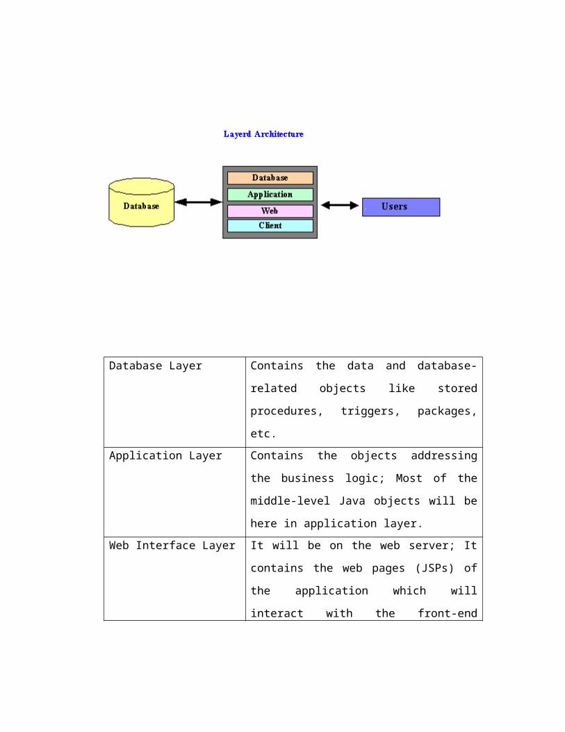
4.2.3.7.2 Layered Architecture
Database Layer Contains the data and database-related objects like
stored procedures, triggers, packages, etc.
Application Layer Contains the objects addressing the business logic;
Most of the middle-level Java objects will be here
in application layer.
Web Interface Layer It will be on the web server; It contains the web
pages (JSPs) of the application which will interact
with the front-end browsers
Client Layer Contains the web browser which interacts with
web server
4.3 DATAFLOW DIAGRAMS
4.3.1 High Level DFD:
1 Location
User Profile
LocID
USER ID AND PASSWORDUser Authentication
2Master Administrator Setup
3Hardware Administrator Setup
4
Purchase
Manager
5Normal User Setup
Users
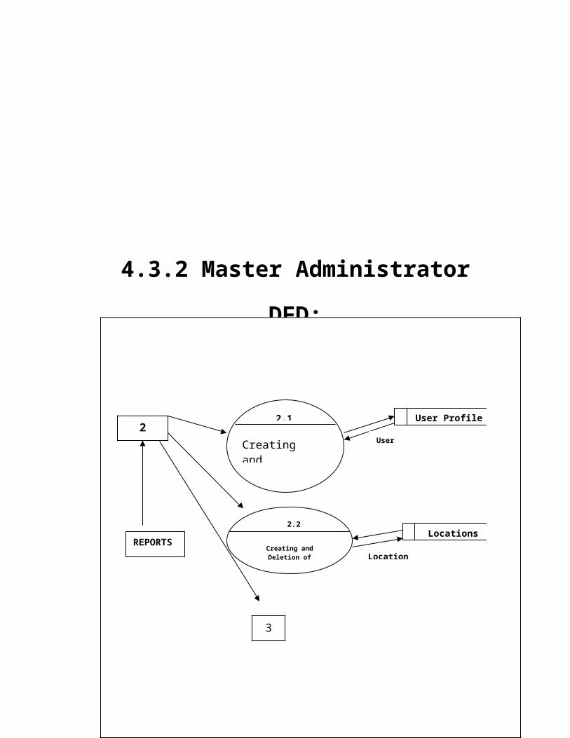
4.3.2 Master Administrator DFD:
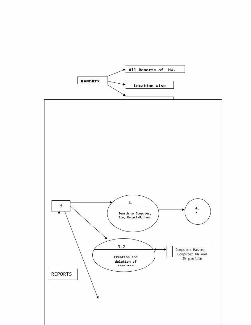
4.3.3 Hardware Administrator DFD:
22.1
Creating and Deleting Users
User Profile
2.2
Creating and Deletion of Locations
3
LocationsREPORTS
REPORTS
All Reports of HW-Admin
Location wise
User wise
User Details
Location Details
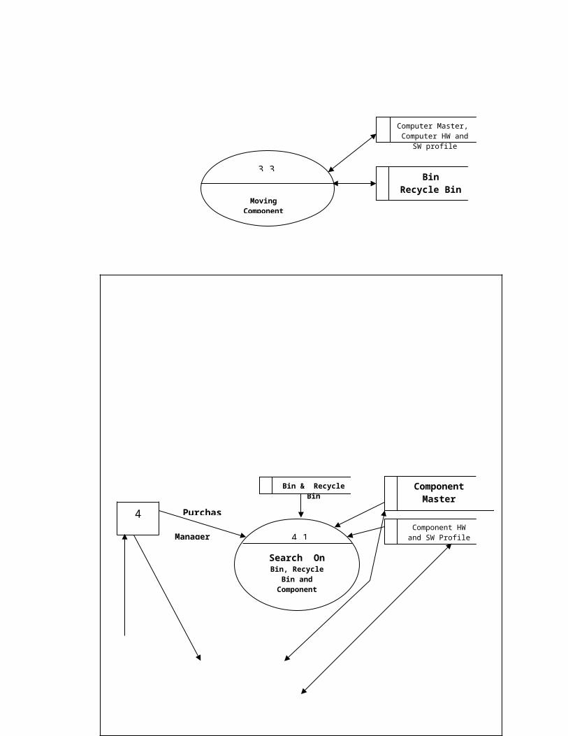
4.3.4 Purchase Manager DFD:
33.1
Search on Computer, Bin, RecycleBin and Component
3.2
Creation and deletion of Computer
3.3
Moving Components
4.1
Computer Master, Computer HW and SW
profile
Computer Master, Computer HW and SW
profile
BinRecycle Bin
REPORTS
REPORTSAll Reports of PM
Computer wise
Component wise
Date Wise
4
4.1
Component Master
Component HW and SW Profile
Purchase
Manager
Bin & Recycle Bin
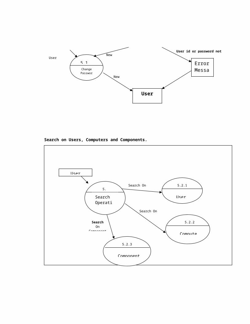
4.3.5 Normal User DFD:
Normal User 5.1
Change Password
User ProfilePassword
Search OnBin, Recycle
Bin and Component
4.2
Edit Bin, Recycle Bin
Component if it is in Shelf
Bin
Recycle Bin
REPORTS
REPORTS
Bin Wise
Component in Shelf
Recycle Bin Wise
5
4.3.6 LOW LEVEL DFD’s:
Change Password DFD
5.2
Search On
User, ComputerComponent
User Profile Figure 1Location
Computer Master
Component Master
5.1
User User Profile
Error Message
User id or password not foundNew Password
Change Password
User
New Password
User details
Search on Users, Computers and Components.
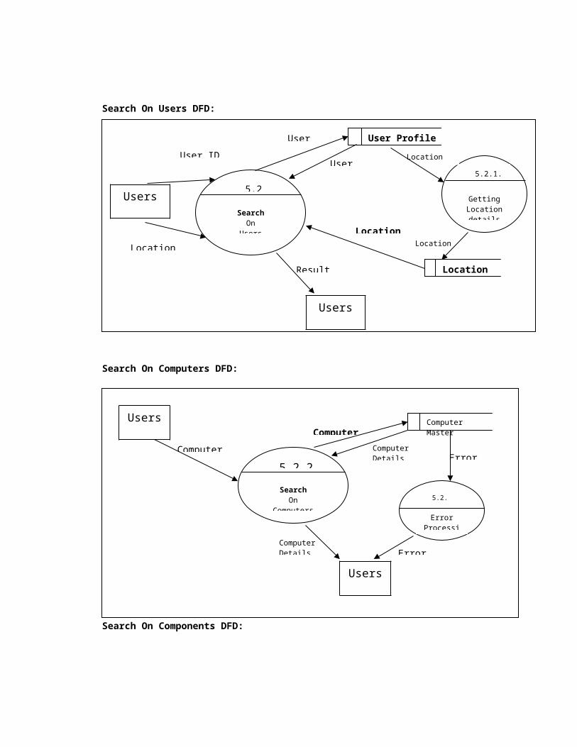
Search On Users DFD:
5.2
Search Operation
5.2.1
Users
5.2.2
Computers
5.2.3
Component
Search On Users
Search On Computers
SearchOn
Component
5.2.1
SearchOn
Users
User ID
Location ID
User ProfileUser ID
User Details
Location
5.2.1.1
Getting Location details
Location ID
Location IDLocation
Users
Result
Users
User

Search On Computers DFD:
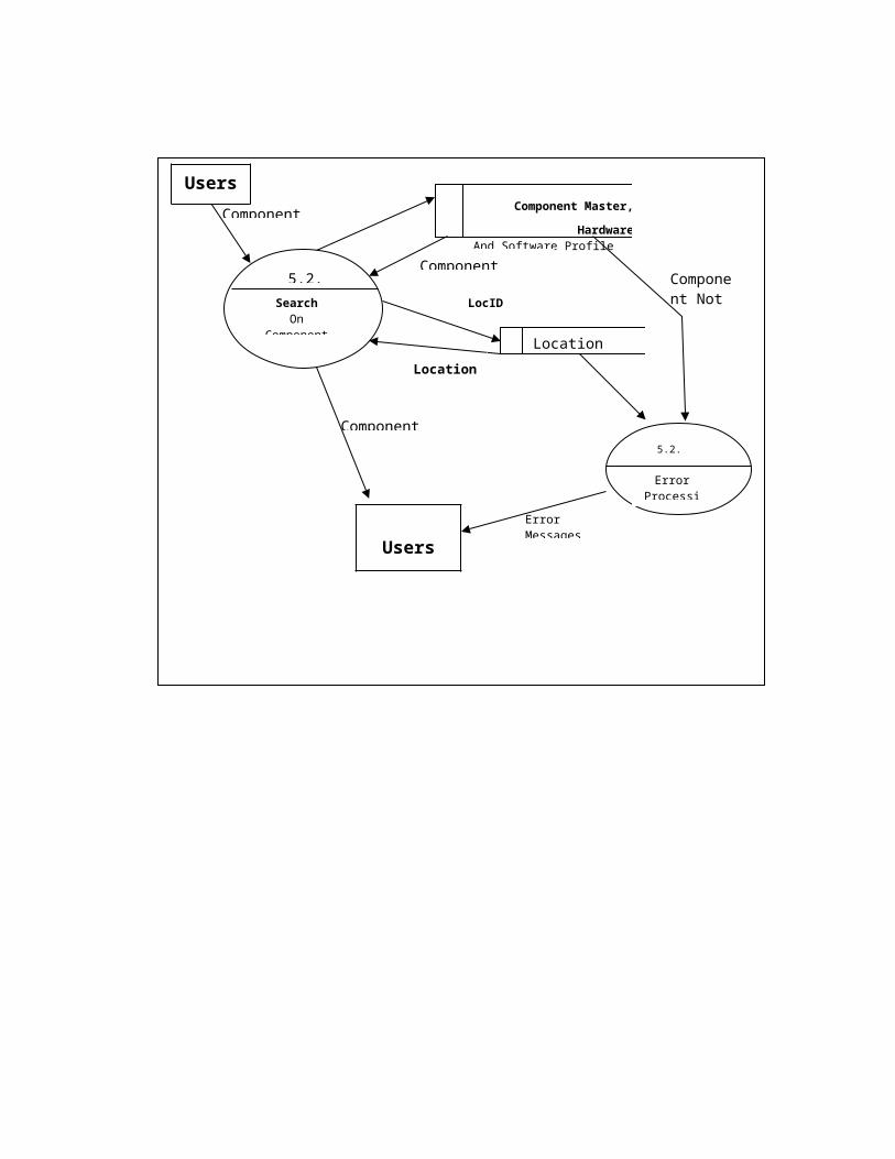
Search On Components DFD:
5.2.2
SearchOn
Computers
Computer ID
Computer Master
Computer ID
Users
5.2.2.1
Error Processing
Error
Error Message
Computer Details
Computer Details
5.2.3
SearchOn
Components
Component ID Component Master, HardwareAnd Software Profile
Location
Component Details
LocID
Location
5.2.3.1
Error Processing
Component Not found
Users
Error Messages
Component Details
Users
Users
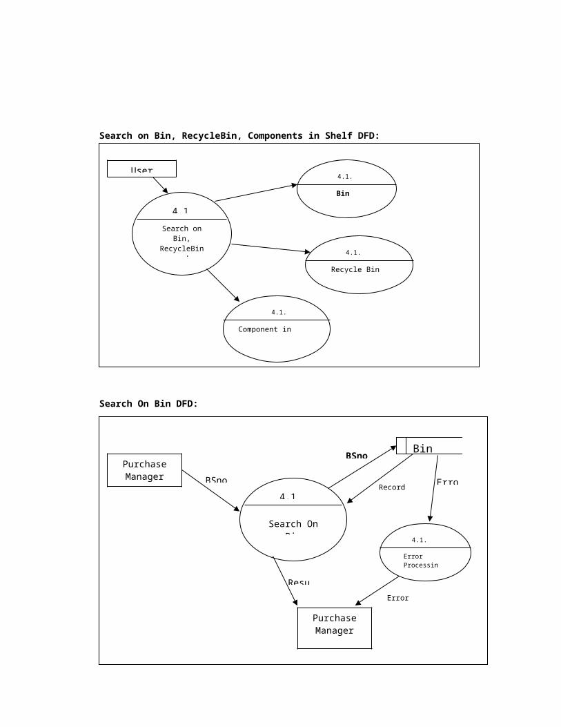
Search on Bin, RecycleBin, Components in Shelf DFD:
Search On Bin DFD:
4.1
Search on Bin, RecycleBin and Component in
Shelf
4.1.1
Bin
4.1.2
Recycle Bin
4.1.3
Component in Shelf
Purchase Manager BSno
BinBSno
Error
User
Search On Recycle Bin DFD:
Search On Component DFD:
4.1.1
Search On Bin
Record Details
4.1.1.1
Error Processing
Purchase Manager
Error Message
Result
Purchase Manager
4.1.1
RBSno
Search On Recycle Bin
Recycle BinRBSno
Record Details
Error
4.1.1.1
Error Processing
Purchase Manager
Error Message
Result
Purchase Manager
4.1.1
Component ID
Component Master,
HW&SW Profile
Record DetailsError
Component ID
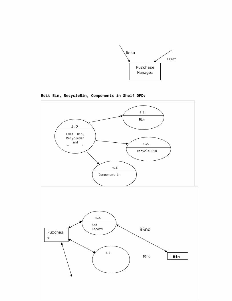
Edit Bin, RecycleBin, Components in Shelf DFD:
Edit Bin DFD:
Search On Recycle Bin 4.1.1.1
Error Processing
Purchase Manager
Error Message
Result
4.2
Edit Bin, RecycleBin and Component in
Shelf
4.2.1
Bin
4.2.2
Recycle Bin
4.2.3
Component in Shelf
Purchase Manager
4.2.1.1
Add Record
4.2.1.2
Delete Record
Bin
BSno and
Other
BSno
Error
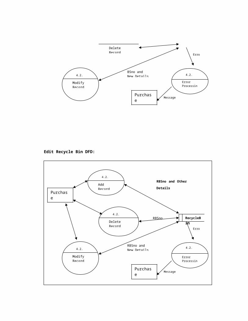
Edit Recycle Bin DFD:
4.2.1.3
Modify Record
BSno and New Details 4.2.1.4
Error Processing
Purchase Manager
Message
Purchase Manager
4.2.2.1
Add Record
4.2.2.2
4.2.2.3
Delete Record
Modify Record
RecycleBin
RBSno and Other
Details
RBSno
RBSno and New Details 4.2.2.4
Error Processing
Error
Purchase Manager Message

Edit Component DFD:
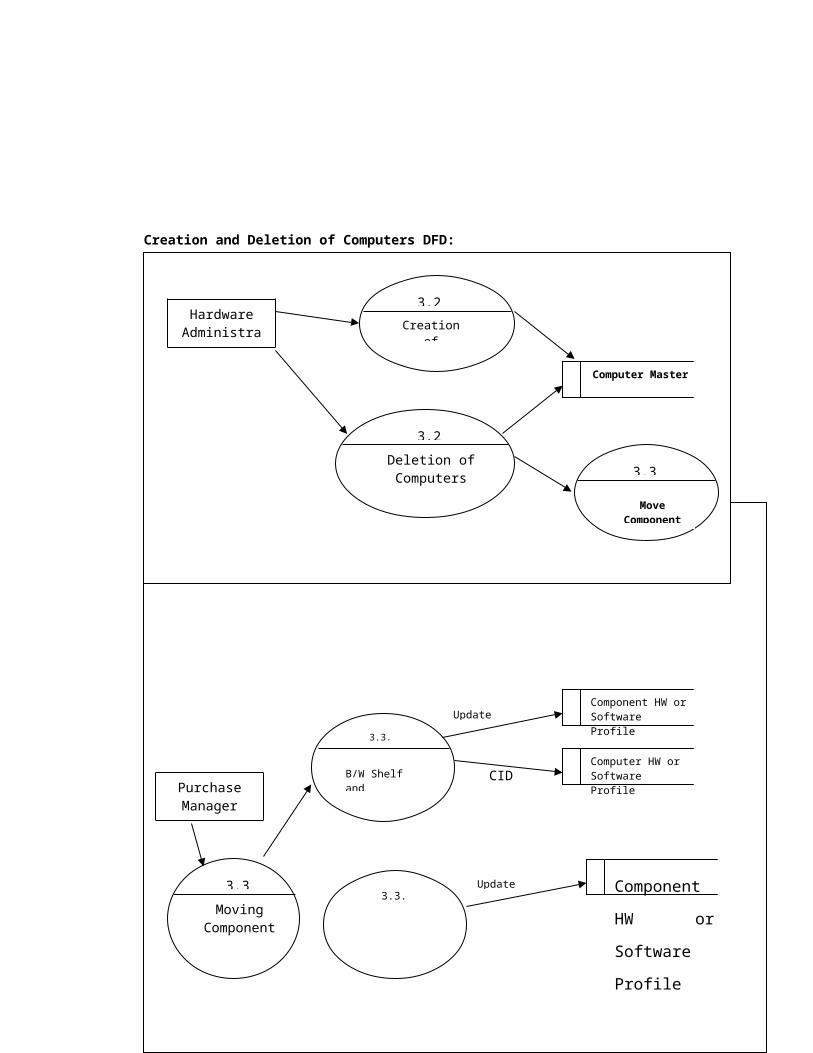
Creation and Deletion of Computers DFD:
Purchase Manager
4.2.2.1
Add Record
4.2.2.2
4.2.2.3
Delete Record If Status is Shelf
Modify Record If Status is Shelf
Component Master,
HW&SW Profile
CID and Other
Details
CID
CID and New Details
4.2.2.4
Error Processing
Error
Purchase Manager Message
Hardware Administrator
3.2.1
Creation of Computer
3.2.2
Deletion of Computers
Computer Master
Move Components
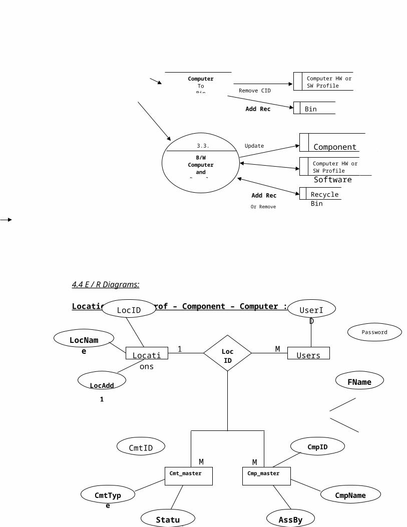
3.3
Moving Components DFD:
4.4 E / R Diagrams:
Location – User_prof – Component – Computer :
3.3
Moving Components
3.3.1
B/W Shelf and Computer
3.3.2
Computer ToBin
3.3.3
B/W Computer
andRecycle Bin
Component HW or Software ProfileUpdate Status
Computer HW or Software ProfileCID
Component
HW or
Software
Profile
Update Status
Computer HW or SW Profile
Remove CID
BinAdd Rec
Component
HW or
Software
Profile
Update Status
Computer HW or SW Profile
RecycleBinAdd Rec
Or Remove
Purchase Manager
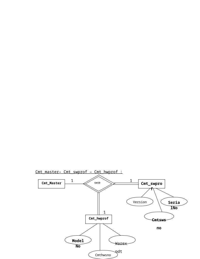
Cmt_master– Cmt_swprof – Cmt_hwprof :
Locations Users
Cmt_master Cmp_master
LocID
UserID
Password
FName
LocAdd
1
CmtID
LocName
LocID
CmtType
Status
CmpName
AssBy
CmpID
1 M
MM
Cmt_master – Cmp_swprof – cmp_hwprof :
Cmt_Master Cmt_swprof
Cmt_hwprof
CmtID
Warexp
dt
ModelNo
Version SerialNo
1 1
1
Cmthwsno
Cmtswsn
o
1

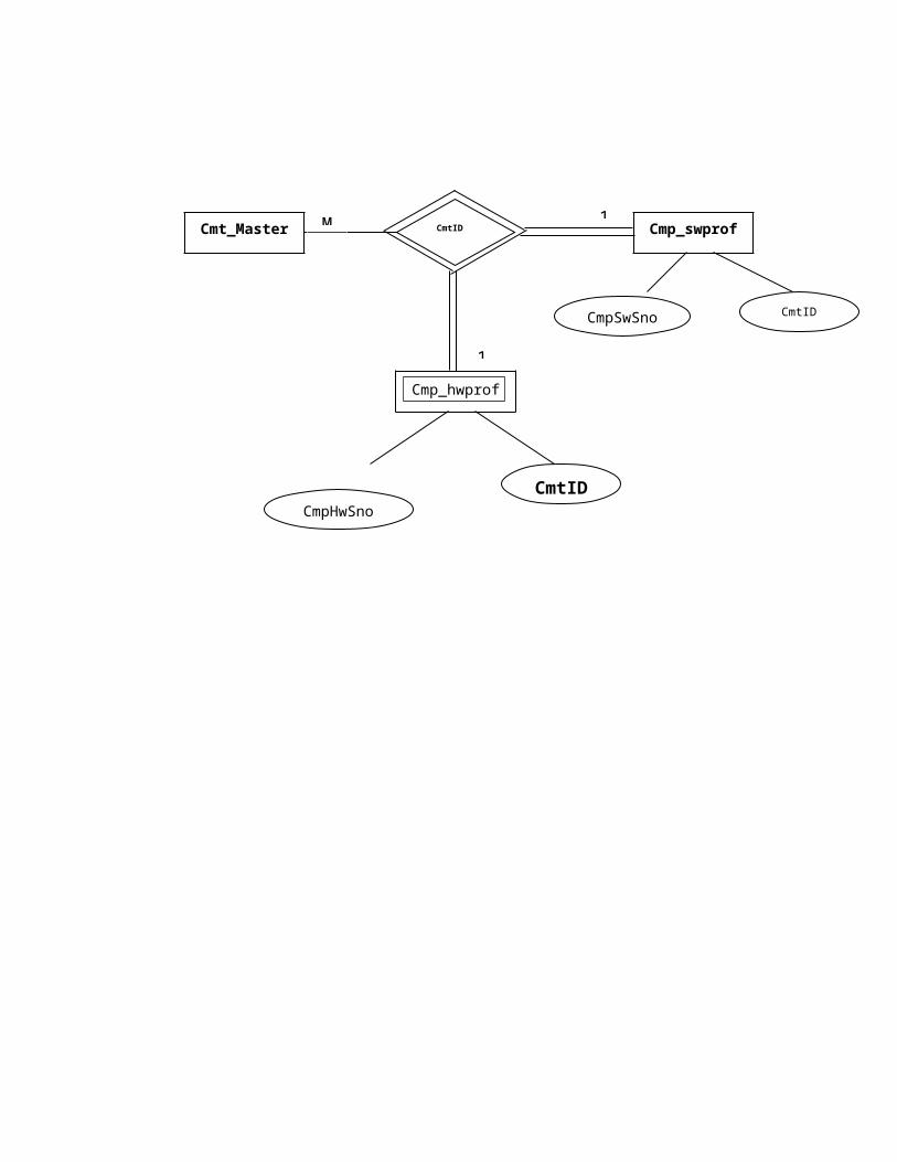
Cmp_master – Cmp_swprof – Cmp_hwprof :
Cmt_Master Cmp_swprof
Cmp_hwprof
CmtID
CmtIDCmpHwSno
CmpSwSno CmtID
M
1
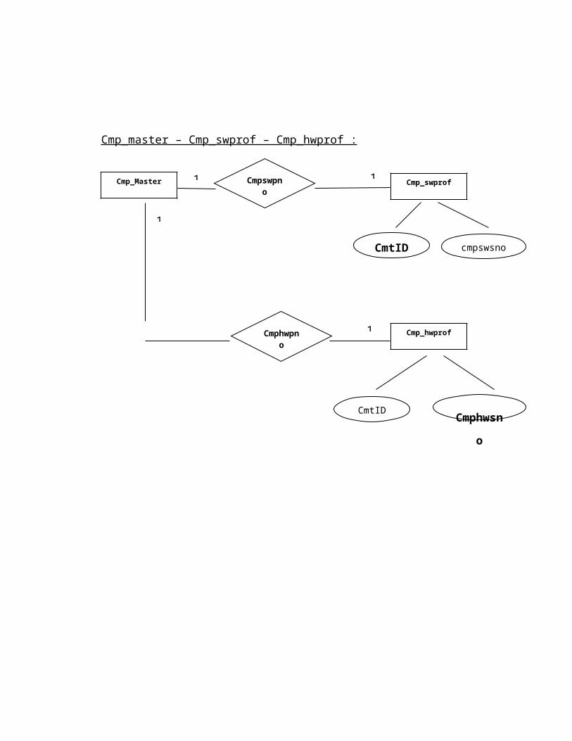
Cmp_Master Cmpswpno
1 1
1
Cmp_swprof

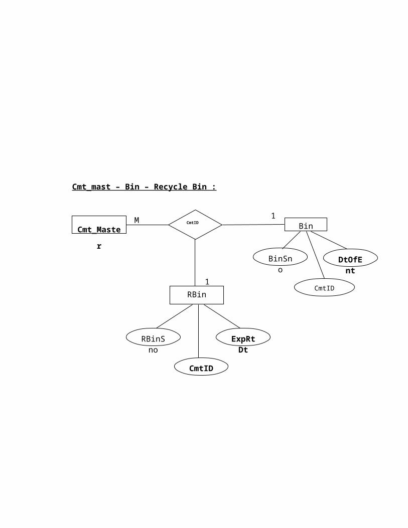
Cmt_mast – Bin – Recycle Bin :
Cmt_MasterCmtID
ExpRtDt
RBinSno
BinSno DtOfEnt
M1
1
CmtID
CmtIDRBin
Bin
Cmphwsn
o
CmtID
CmtID cmpswsno
1Cmphwp
no
Cmp_hwprof
SYSTEM DESIGN
5. SYSTEM DESIGN:
SYSTEM DESIGN phase follows system analysis phase. Design is
maintaining a record proof design divisions and providing a blueprint for the
implementation phase. Design is the bridge between system analysis and
system implementation.
System design is transition from a user oriented, document oriented to
programmers or database personnel. The design is a solution, a “how to”
approach to the creation a new system. This is composed of several steps. It
provides the understanding and procedural details necessary for implementing
the system recommended in the feasibility study. Design goes through logical
and physical stages of development, logical design reviews the present
physical system, prepare input and output specifications, detail the
implementation plan, and prepares a logical design walkthrough.
The database tables are designed by analyzing various functions
involved in the system and the format of the fields is also designed. The fields
in the database table should define their role in the system. The unnecessary
fields should be avoided because it affects the storage areas of the system.
Care is to be taken to encode the lengthy names. Then in the input and the
output screen design, the design should be made user friendly. The menu
should be precise and compact.
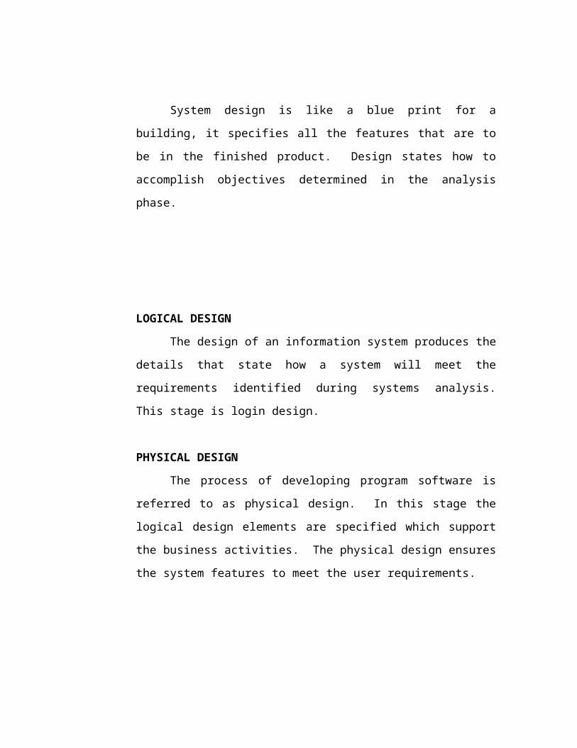
OBJECTIVES OF DESIGN
System design is like a blue print for a building, it specifies all the
features that are to be in the finished product. Design states how to accomplish
objectives determined in the analysis phase.
LOGICAL DESIGN
The design of an information system produces the details that state how
a system will meet the requirements identified during systems analysis. This
stage is login design.
PHYSICAL DESIGN
The process of developing program software is referred to as physical
design. In this stage the logical design elements are specified which support
the business activities. The physical design ensures the system features to
meet the user requirements.

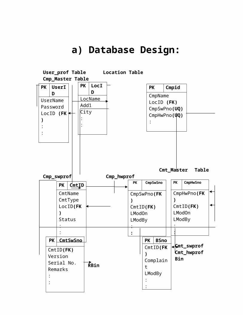
a) Database Design:
User_prof Table Location Table Cmp_Master Table
Cmt_Master Table Cmp_swprof Cmp_hwprof
Cmt_swprof Cmt_hwprof
Bin RBin
PK UserID
UserNamePasswordLocID (FK ) ::
PK Cmpid
CmpNameLocID (FK)CmpSwPno(UQ) CmpHwPno(UQ):
PK LocID
LocNameAdd1City::
PK CmpHwSno
CmpHwPno(FK)CmtID(FK)LModOnLModBy::
PK CmpSwSno
CmpSwPno(FK)CmtID(FK)LModOnLModBy::
PK CmtID
CmtNameCmtTypeLocID(FK)Status::
PK CmtSwSno
CmtID(FK)Version Serial No.Remarks::
PK BSno
CmtID(FK)ComplaintLModBy::
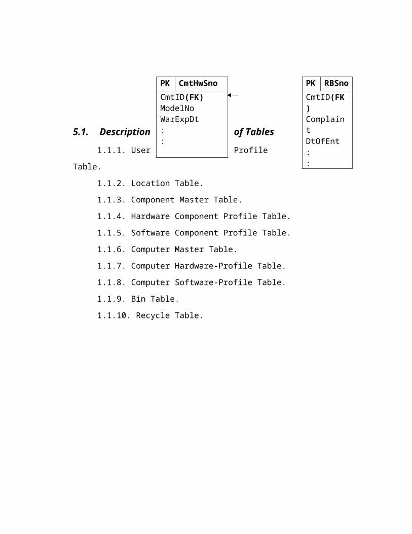
PK CmtHwSno
CmtID(FK)ModelNoWarExpDt::
PK RBSno
CmtID(FK)ComplaintDtOfEnt::
5.1. Description of Tables
1.1.1. User Profile Table.
1.1.2. Location Table.
1.1.3. Component Master Table.
1.1.4. Hardware Component Profile Table.
1.1.5. Software Component Profile Table.
1.1.6. Computer Master Table.
1.1.7. Computer Hardware-Profile Table.
1.1.8. Computer Software-Profile Table.
1.1.9. Bin Table.
1.1.10. Recycle Table.
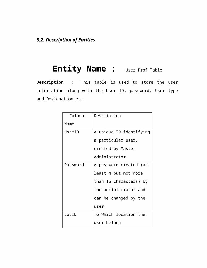
5.2. Description of Entities
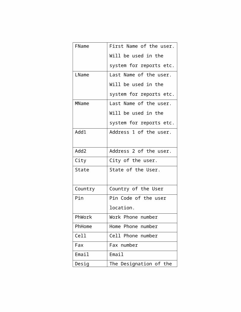
Entity Name : User_Prof Table
Description : This table is used to store the user information along with the User ID,
password, User type and Designation etc.
Column Name Description
UserID A unique ID identifying a
particular user, created by Master
Administrator.
Password A password created (at least 4 but
not more than 15 characters) by
the administrator and can be
changed by the user.
LocID To Which location the user
belong
FName First Name of the user. Will be
used in the system for reports etc.
LName Last Name of the user. Will be
used in the system for reports etc.
MName Last Name of the user. Will be
used in the system for reports etc.
Add1 Address 1 of the user.
Add2 Address 2 of the user.
City City of the user.
State State of the User.
Country Country of the User
Pin Pin Code of the user location.
PhWork Work Phone number
PhHome Home Phone number
Cell Cell Phone number
Fax Fax number
Email Email
Desig The Designation of the user.
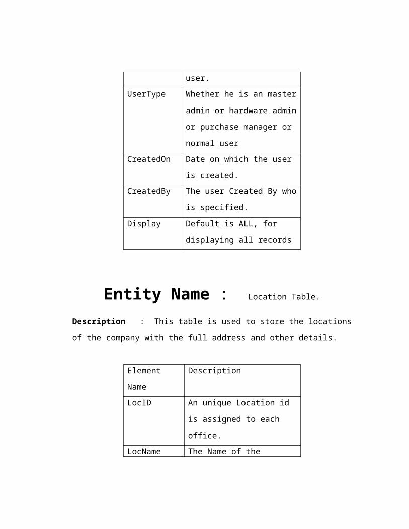
UserType Whether he is an master admin or
hardware admin or purchase
manager or normal user
CreatedOn Date on which the user is created.

CreatedBy The user Created By who is
specified.
Display Default is ALL, for displaying all
records
Entity Name : Location Table.
Description : This table is used to store the locations of the company with the full
address and other details.
Element Name Description
LocID An unique Location id is
assigned to each office.
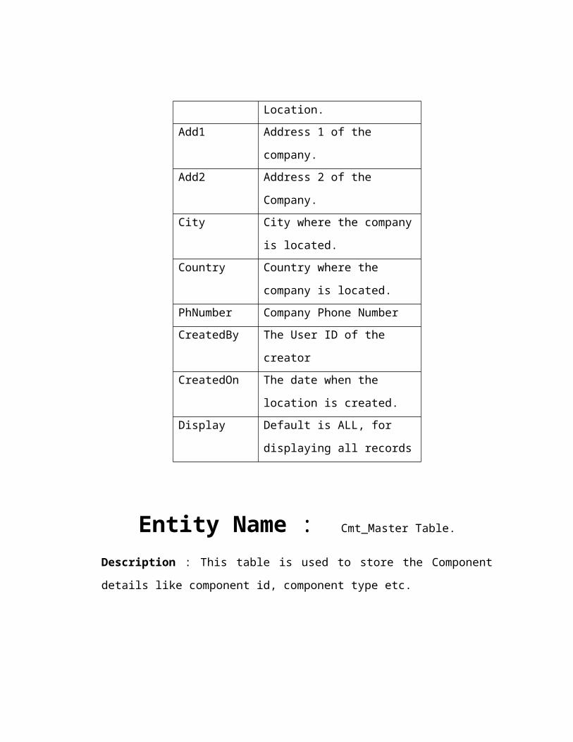
LocName The Name of the Location.
Add1 Address 1 of the company.
Add2 Address 2 of the Company.
City City where the company is
located.
Country Country where the company is
located.
PhNumber Company Phone Number
CreatedBy The User ID of the creator
CreatedOn The date when the location is
created.
Display Default is ALL, for displaying all
records
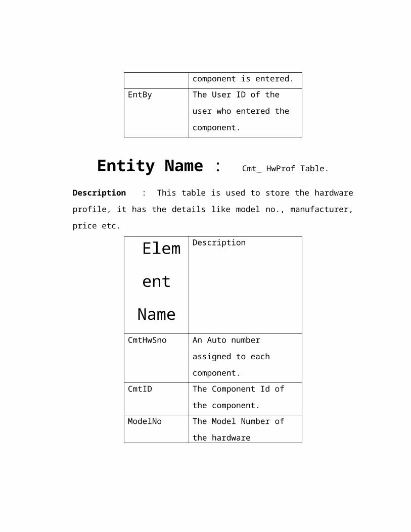
Entity Name : Cmt_Master Table.
Description : This table is used to store the Component details like component id,
component type etc.
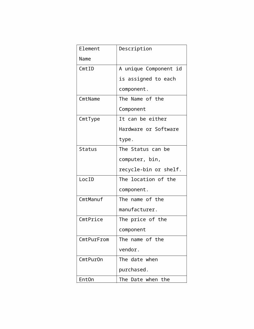
Element Name Description
CmtID A unique Component id is
assigned to each component.
CmtName The Name of the Component
CmtType It can be either Hardware or
Software type.
Status The Status can be computer,
bin, recycle-bin or shelf.
LocID The location of the component.
CmtManuf The name of the manufacturer.
CmtPrice The price of the component
CmtPurFrom The name of the vendor.
CmtPurOn The date when purchased.
EntOn The Date when the component
is entered.
EntBy The User ID of the user who
entered the component.
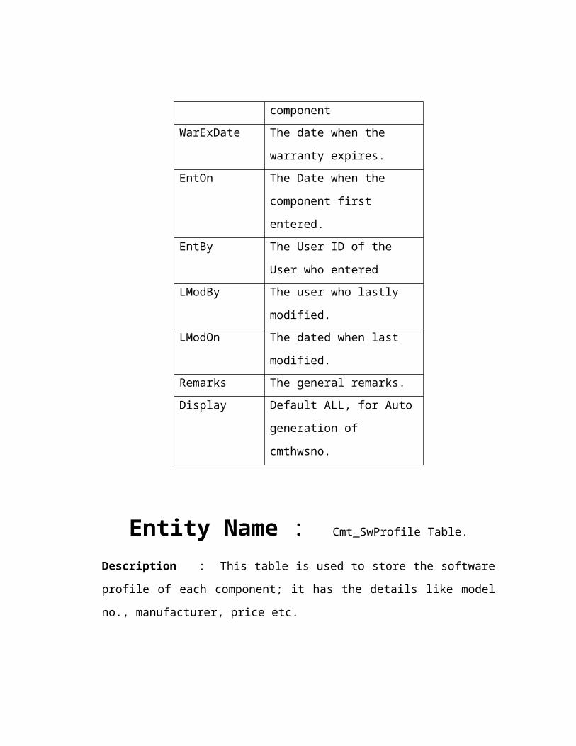
Entity Name : Cmt_ HwProf Table.
Description : This table is used to store the hardware profile, it has the details like
model no., manufacturer, price etc.
Elemen
t Name
Description
CmtHwSno An Auto number assigned to
each component.
CmtID The Component Id of the
component.
ModelNo The Model Number of the
hardware component
WarExDate The date when the warranty
expires.
EntOn The Date when the component
first entered.
EntBy The User ID of the User who
entered
LModBy The user who lastly modified.
LModOn The dated when last modified.
Remarks The general remarks.
Display Default ALL, for Auto
generation of cmthwsno.
Entity Name : Cmt_SwProfile Table.
Description : This table is used to store the software profile of each component; it
has the details like model no., manufacturer, price etc.
Elemen
t Name
Description
CmtSwSno An Auto number assigned to
each software component.
CmtID The Component Id of the
component.
Version The version number
SerialNo The Serial Number of the s/w
SWDate The Date in the Software.
LModOn The Date when the component
first entered.
LModBy The User ID of the User who
entered
Remarks The general remarks.
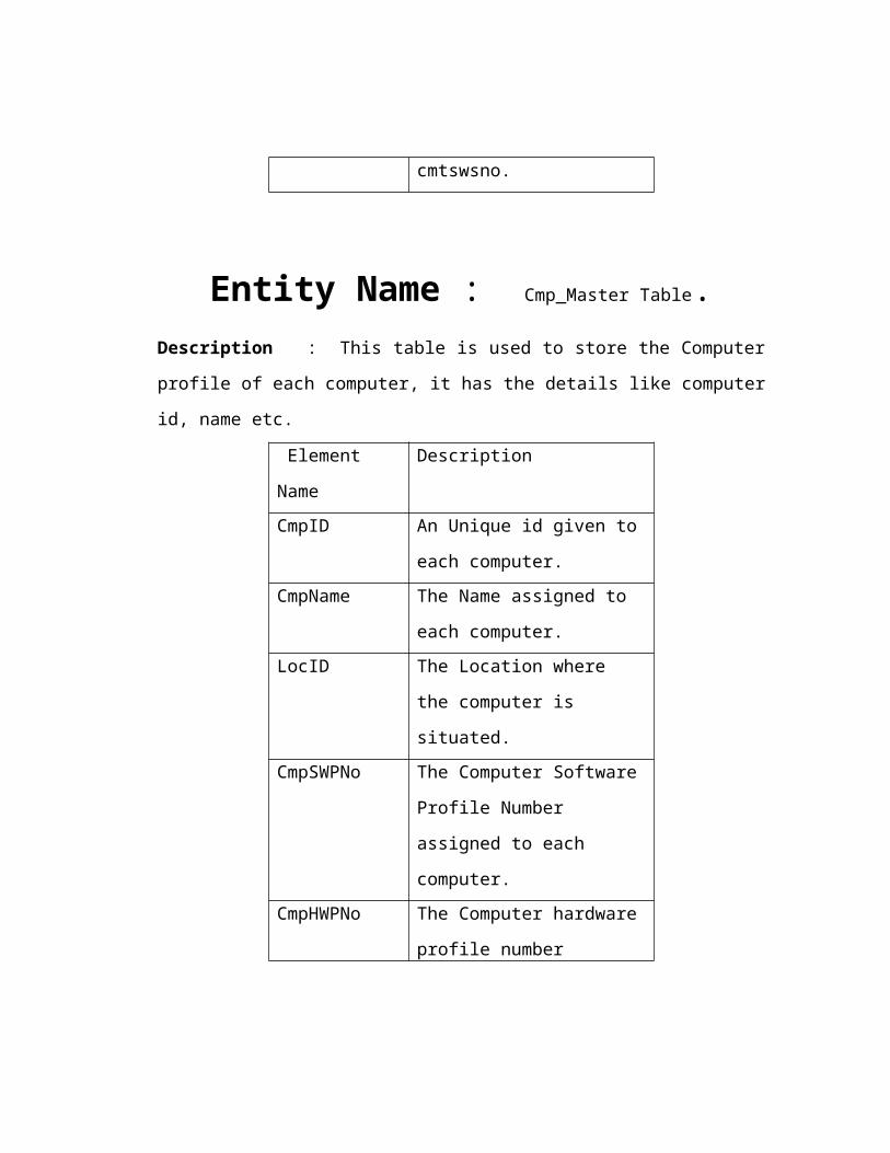
Display Default ALL, for Auto
generation of cmtswsno.

Entity Name : Cmp_Master Table.Description : This table is used to store the Computer profile of each computer, it
has the details like computer id, name etc.
Element Name Description
CmpID An Unique id given to each
computer.
CmpName The Name assigned to each
computer.
LocID The Location where the
computer is situated.
CmpSWPNo The Computer Software Profile
Number assigned to each
computer.
CmpHWPNo The Computer hardware profile
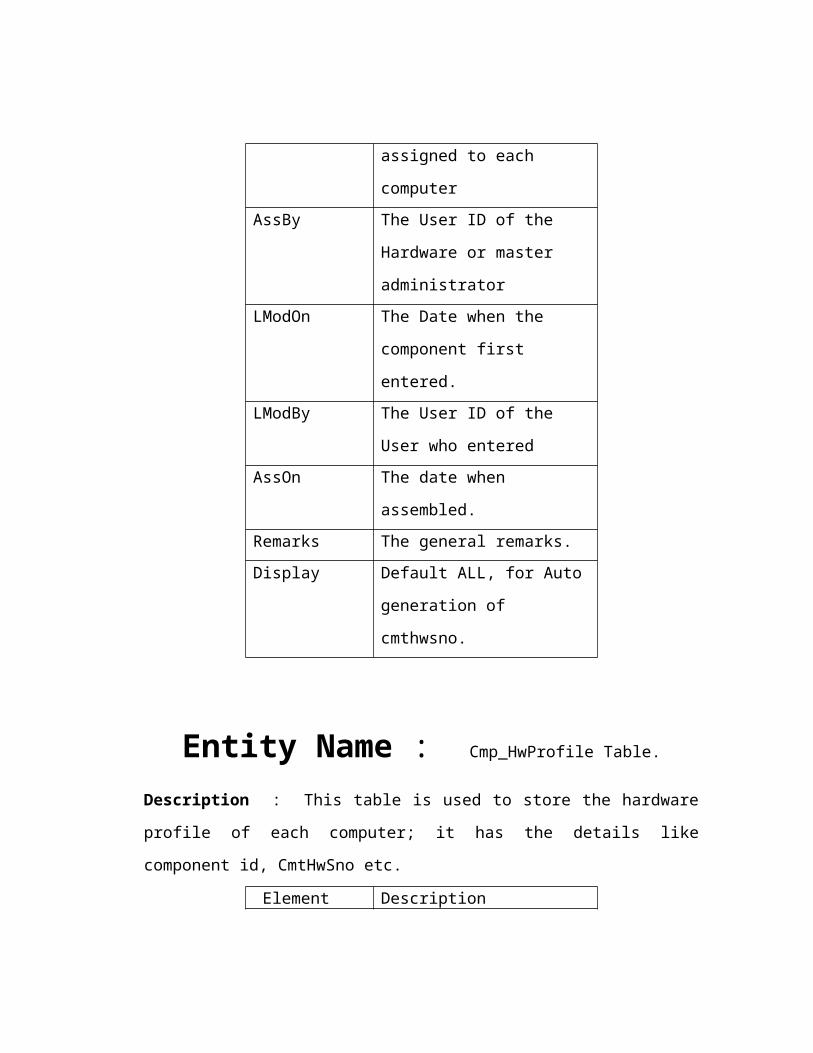
number assigned to each
computer
AssBy The User ID of the Hardware or
master administrator
LModOn The Date when the component
first entered.
LModBy The User ID of the User who
entered
AssOn The date when assembled.
Remarks The general remarks.
Display Default ALL, for Auto
generation of cmthwsno.
Entity Name : Cmp_HwProfile Table.
Description : This table is used to store the hardware profile of each computer; it has
the details like component id, CmtHwSno etc.
Element Name Description
CmpHw
Sno
The unique number assigned.
CmpHwPno The Computer hardware profile
number
CmtID The Component id of the
component.
LModBy The user who lastly modified.
LModOn The dated when last modified.
Remarks The general remarks.
Display Default ALL, for Auto
generation of cmphwsno.
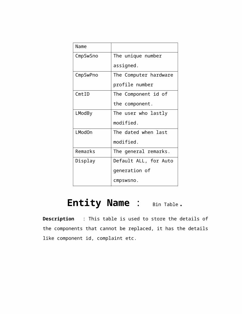
Entity Name : Cmp_SwProfile Table.
Description : This table is used to store the software profile of each computer, it has
the details like component id, CSSno etc.
Element Name Description
CmpSwSno The unique number assigned.
CmpSwPno The Computer hardware profile
number
CmtID The Component id of the
component.
LModBy The user who lastly modified.
LModOn The dated when last modified.
Remarks The general remarks.
Display Default ALL, for Auto
generation of cmpswsno.
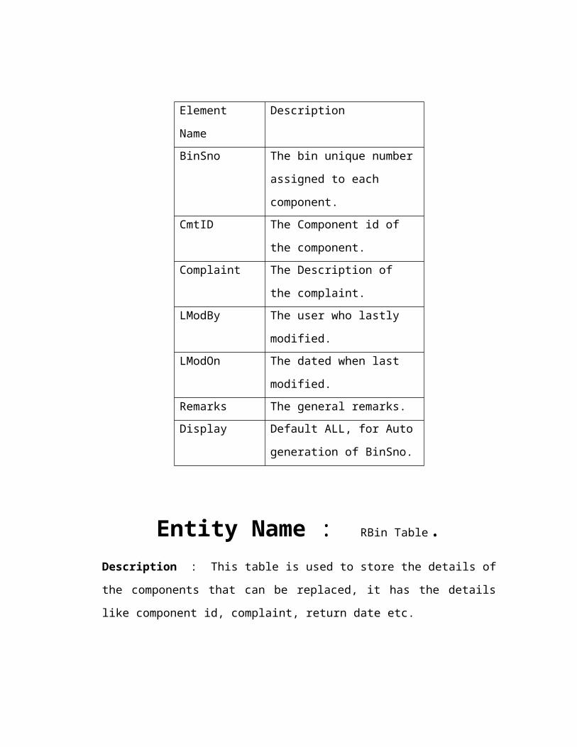
Entity Name : Bin Table.Description : This table is used to store the details of the components that cannot be
replaced, it has the details like component id, complaint etc.
Element Name Description
BinSno The bin unique number assigned
to each component.
CmtID The Component id of the
component.
Complaint The Description of the
complaint.
LModBy The user who lastly modified.
LModOn The dated when last modified.
Remarks The general remarks.
Display Default ALL, for Auto
generation of BinSno.
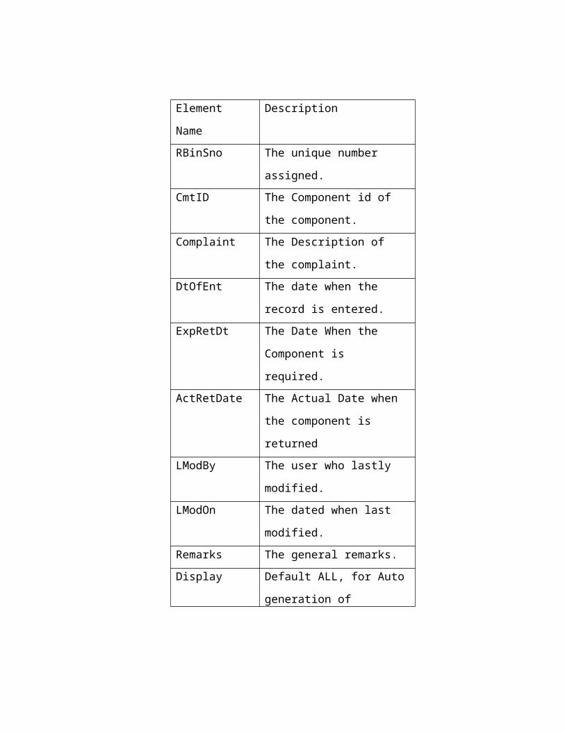
Entity Name : RBin Table.Description : This table is used to store the details of the components that can be
replaced, it has the details like component id, complaint, return date etc.
Element Name Description
RBinSno The unique number assigned.
CmtID The Component id of the
component.
Complaint The Description of the
complaint.
DtOfEnt The date when the record is
entered.
ExpRetDt The Date When the Component
is required.
ActRetDate The Actual Date when the
component is returned
LModBy The user who lastly modified.
LModOn The dated when last modified.
Remarks The general remarks.
Display Default ALL, for Auto
generation of RBinSno.
5. 3 TECHNICAL SPECIFICATIONS (USER INTERFACE DESIGN)
5.3.1 Login Module:
Module Name: Login Module
Functionality : The existing Users, Administrators or Master administrator
can login into the system using User Id and password. User authentication is
done in the login screen. If the user enters the incorrect User Id or Password
the corresponding error page is given.
Module Type : Screen
Input Parameters:
Parameter
Name
Data type
(Length)
Mandatory Validation
UserID Varchar2 (10) Y A UserID should be of at
least 5 and not more than
15 characters
Password Varchar2 (15) Y A Password of at least 5
but not more than 15
characters
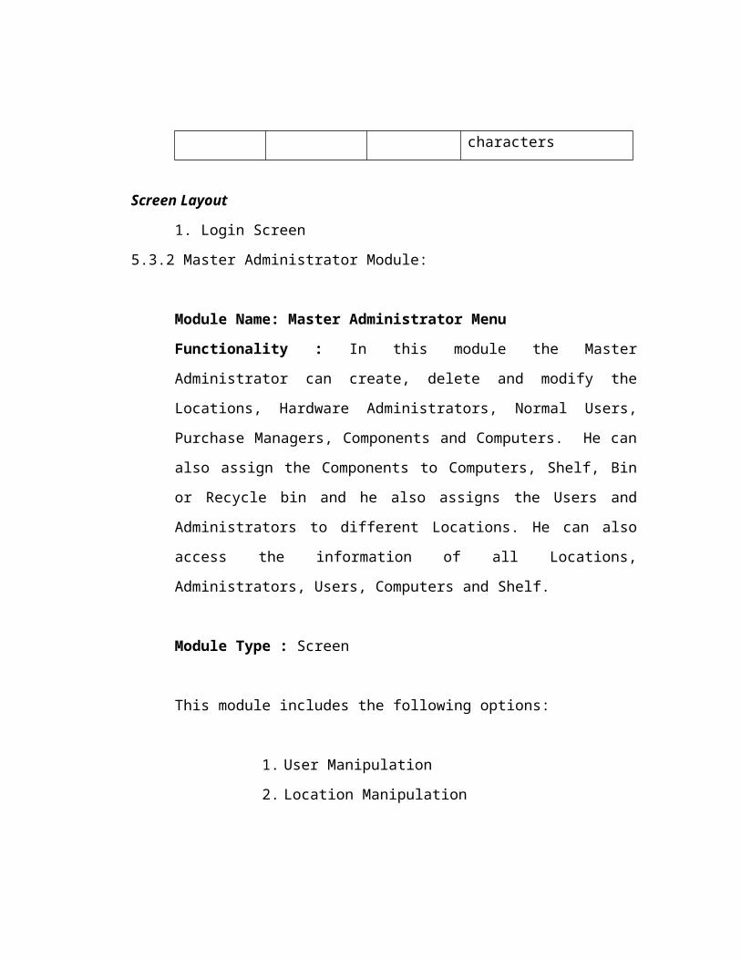
Screen Layout
1. Login Screen
5.3.2 Master Administrator Module:
Module Name: Master Administrator Menu
Functionality : In this module the Master Administrator can create, delete and
modify the Locations, Hardware Administrators, Normal Users, Purchase
Managers, Components and Computers. He can also assign the Components to
Computers, Shelf, Bin or Recycle bin and he also assigns the Users and
Administrators to different Locations. He can also access the information of all
Locations, Administrators, Users, Computers and Shelf.
Module Type : Screen
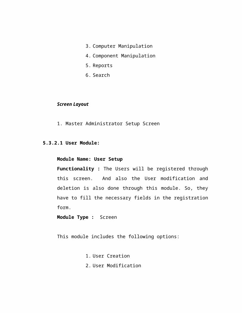
This module includes the following options:
1. User Manipulation
2. Location Manipulation
3. Computer Manipulation
4. Component Manipulation
5. Reports
6. Search
Screen Layout
1. Master Administrator Setup Screen
5.3.2.1 User Module:
Module Name: User Setup
Functionality : The Users will be registered through this screen. And also the
User modification and deletion is also done through this module. So, they have
to fill the necessary fields in the registration form.
Module Type : Screen
This module includes the following options:
1. User Creation
2. User Modification
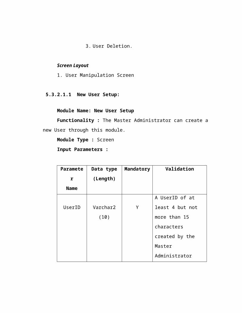
3. User Deletion.
Screen Layout
1. User Manipulation Screen
5.3.2.1.1 New User Setup:
Module Name: New User Setup
Functionality : The Master Administrator can create a new User through this
module.
Module Type : Screen
Input Parameters :
Parameter
Name
Data type
(Length)
Mandatory Validation
UserID Varchar2 (10) Y
A UserID of at least 4 but
not more than 15
characters created by the
Master Administrator
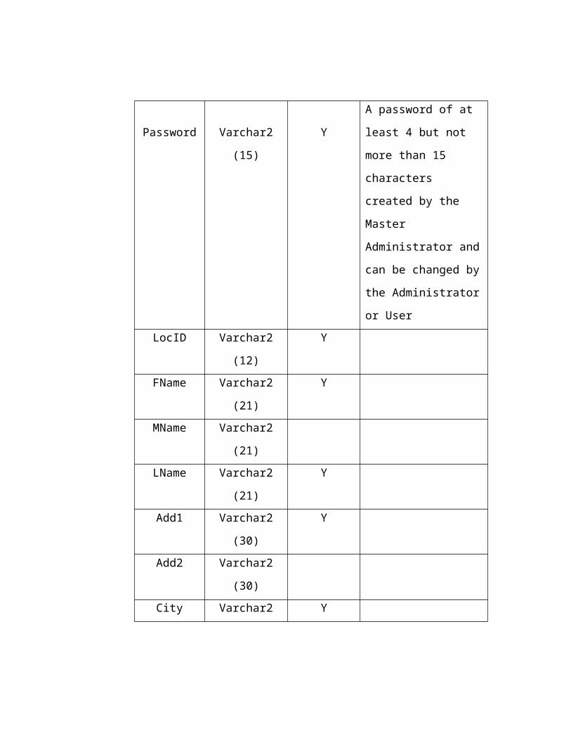
Password Varchar2 (15) Y
A password of at least 4
but not more than 15
characters created by the
Master Administrator and
can be changed by the
Administrator or User
LocID Varchar2 (12) Y
FName Varchar2 (21) Y
MName Varchar2 (21)
LName Varchar2 (21) Y
Add1 Varchar2 (30) Y
Add2 Varchar2 (30)
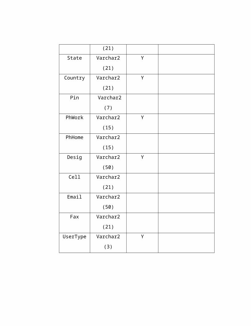
City Varchar2 (21) Y
State Varchar2 (21) Y
Country Varchar2 (21) Y
Pin Varchar2 (7)
PhWork Varchar2 (15) Y
PhHome Varchar2 (15)
Desig Varchar2 (50) Y
Cell Varchar2 (21)
Email Varchar2 (50)
Fax Varchar2 (21)
UserType Varchar2 (3) Y
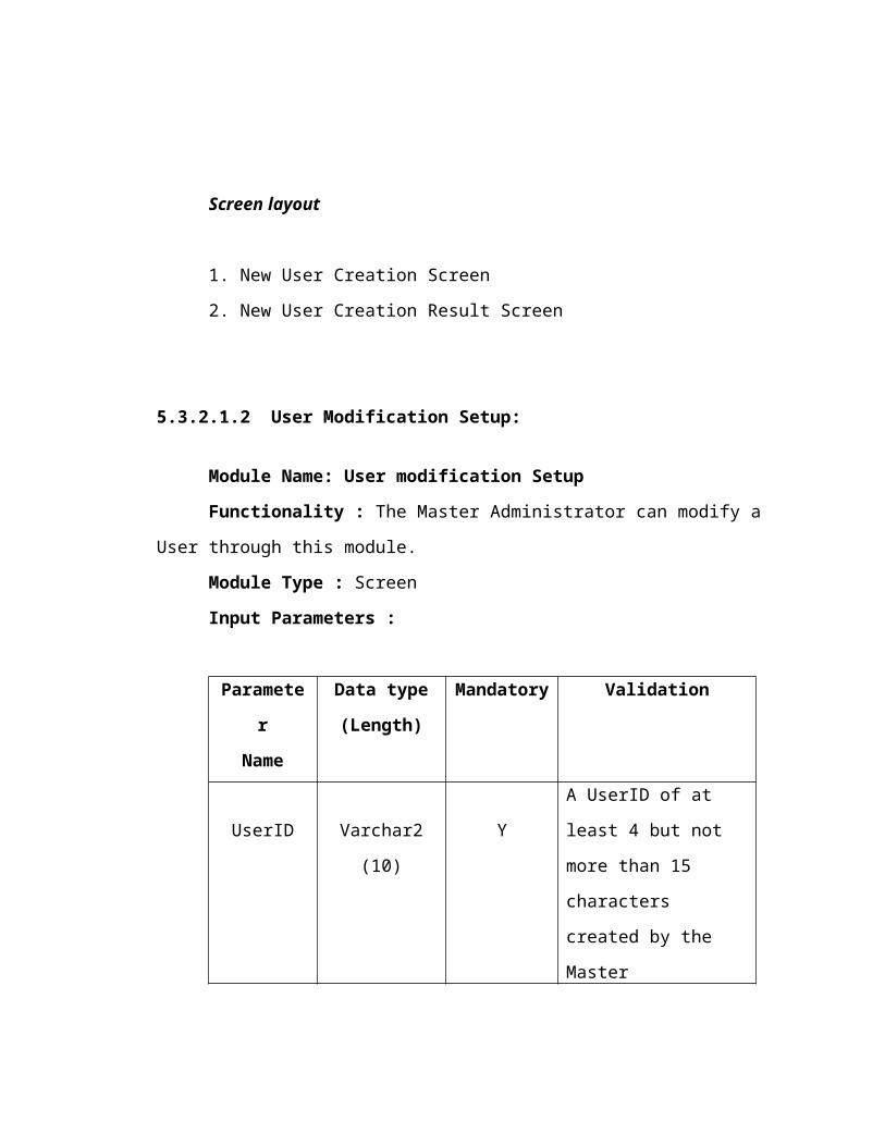
Screen layout
1. New User Creation Screen
2. New User Creation Result Screen
5.3.2.1.2 User Modification Setup:
Module Name: User modification Setup
Functionality : The Master Administrator can modify a User through this
module.
Module Type : Screen
Input Parameters :
Parameter
Name
Data type
(Length)
Mandatory Validation
UserID Varchar2 (10) Y
A UserID of at least 4 but
not more than 15
characters created by the
Master Administrator
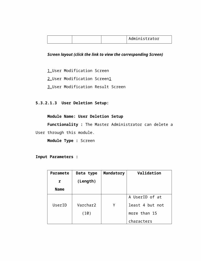
Screen layout (click the link to view the corresponding Screen)
1.User Modification Screen
2.User Modification Screen1
3.User Modification Result Screen
5.3.2.1.3 User Deletion Setup:
Module Name: User Deletion Setup
Functionality : The Master Administrator can delete a User through this
module.
Module Type : Screen
Input Parameters :
Parameter
Name
Data type
(Length)
Mandatory Validation
UserID Varchar2 (10) Y
A UserID of at least 4 but
not more than 15
characters created by the
Master Administrator
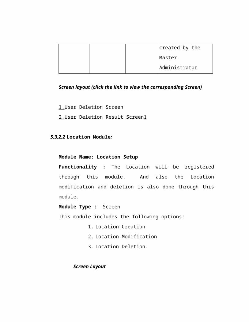
Screen layout (click the link to view the corresponding Screen)
1.User Deletion Screen
2.User Deletion Result Screen1
5.3.2.2 Location Module:
Module Name: Location Setup
Functionality : The Location will be registered through this module. And also
the Location modification and deletion is also done through this module.
Module Type : Screen
This module includes the following options:
1. Location Creation
2. Location Modification
3. Location Deletion.
Screen Layout
1. Location Manipulation Screen
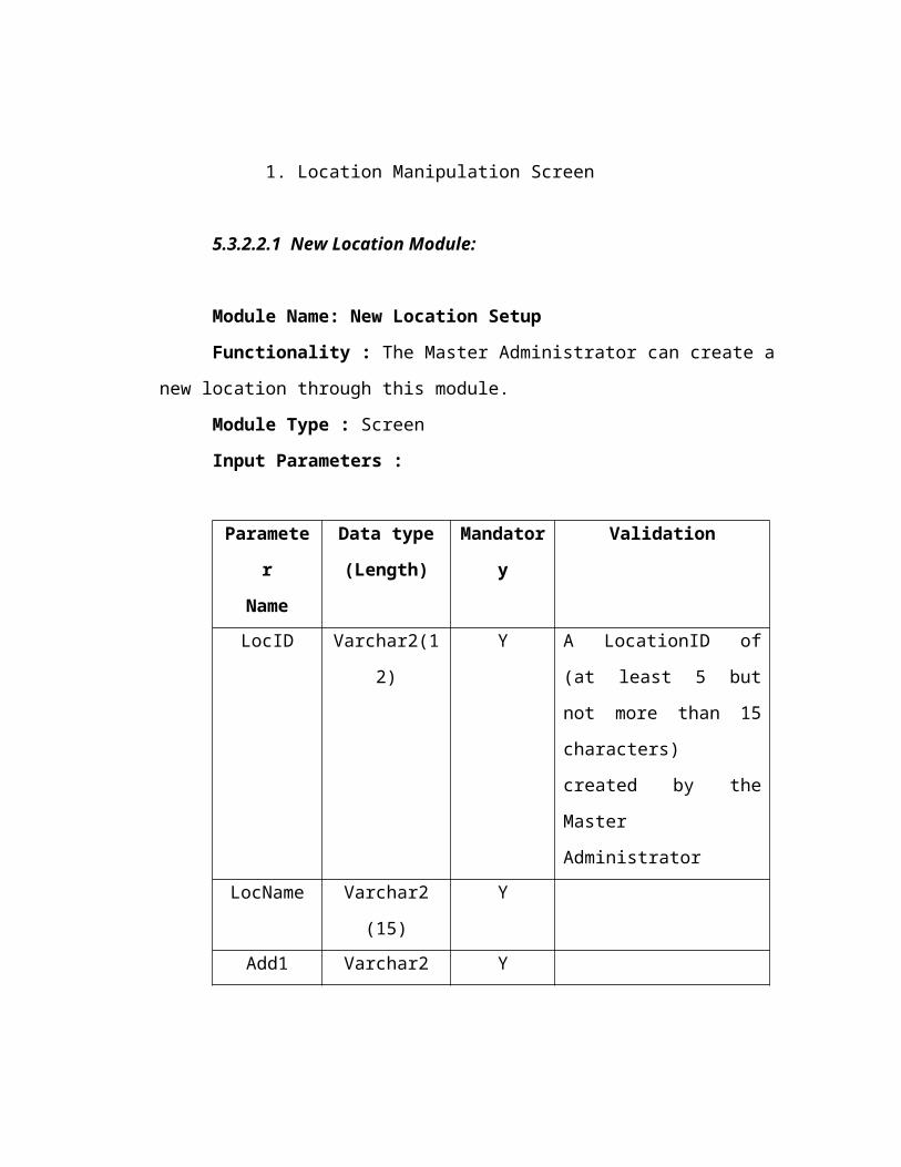
5.3.2.2.1 New Location Module:
Module Name: New Location Setup
Functionality : The Master Administrator can create a new location through
this module.
Module Type : Screen
Input Parameters :
Parameter
Name
Data type
(Length)
Mandatory Validation
LocID Varchar2(12) Y A LocationID of (at least 5
but not more than 15
characters) created by the
Master Administrator
LocName Varchar2 (15) Y
Add1 Varchar2 (30) Y
Add2 Varchar2 (30)
City Varchar2 (15) Y
State Varchar2 (15)
Country Varchar2 (15) Y
PhNumber Varchar2 (15)
Screen layout
1. New Location Creation Screen
2. New Location Creation Result Screen
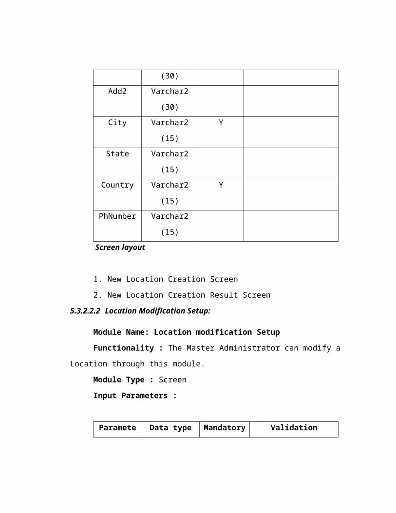
5.3.2.2.2 Location Modification Setup:
Module Name: Location modification Setup
Functionality : The Master Administrator can modify a Location through this
module.
Module Type : Screen
Input Parameters :
Parameter
Name
Data type
(Length)
Mandatory Validation
LocID Varchar2 (12) Y
A LocID of at least 4 but
not more than 15
characters created by the
Master Administrator
Screen layout (click the link to view the corresponding Screen)
1.Location Modification Screen
2.Location Modification Screen1
3.Location Modification Result Screen
5.3.2.2.3 Location Deletion Setup:
Module Name: Location Deletion Setup
Functionality : The Master Administrator can delete a Location through this
module.
Module Type : Screen
Input Parameters :
Parameter
Name
Data type
(Length)
Mandatory Validation
LocID Varchar2 (12) Y
A LocID of at least 4 but
not more than 15
characters created by the
Master Administrator
Screen layout
1.Location Deletion Screen
2.Location Deletion Result Screen1
5.3.2.3 Component Module:
Module Name: Component Setup
Functionality : The Component will be registered through this module. Also
the component modification, moving between shelf-others and deletion is also
done through this module.
Module Type : Screen
This module includes the following options:
1. Component Creation
2. Component Modification
3. Component Moving
4. Component Deletion.
Screen Layout
1. Component Manipulation Screen
5.3.2.3.1 New Component Module:
Module Name: New Component Setup
Functionality : A Component is entered into the Shelf by giving a unique
Component Id and type of the Component. Type may be either S/W or H/W.
Basing on the type the other details will be entered.
Module Type : Screen
Input Parameters :
Parameter
Name
Data type
(Length)
Mandatory Validation
CmtID Varchar2 (12) Y
CmtName Varchar2 (21) Y
CmtType Varchar2 (3) Y It should be either
‘HW’ – H/W or ‘SW’ –
S/W
LocID Varchar2 (12) Y
CmtManuf Varchar2 (21) Y
Status Varchar2 (2) Y It should be either ‘S’-
Shelf, ‘B’ – Bin, ‘R’ –
Recycle bin, ‘C’ –
Computer
CmtPrice Number (8,2) Y
CmtPurFrom Varchar2 (21) Y
CmtPurOn Date Y
If the Component type is SW (Software) then the Additional input parameters
are as follows.
Input Parameters(SW) :
Parameter
Name
Data type
(Length)
Mandatory Validation
CmtSwsno Number(38) Is the primary key,
generated
automatically.
CmtID Varchar2 (12) Y Foreign key from
cmt_master
Version Varchar2 (5) Y
SerialNo. Varchar2 (15) Y
SwDate Date Y
Remarks Varchar2 (30)
If the Component type is HW (Hardware) then the Additional input parameters
are as follows.
Input Parameters (HW) :
Parameter
Name
Data type
(Length)
Mandatory Validation
CmtHwSno Number(38) Is the primary key,
generated
automatically.
CmtID Varchar2 (12) Y Foreign key from
cmt_master
ModelNo Varchar2 (15) Y
WarExpDate Date Y
Remarks Varchar2 (30)
Screen layout
1. New Component Creation Screen
2. New Component-Hardware Creation Screen
3. New Component Creation Result Screen
5.3.2.3.2 Component Modification Setup:
Module Name: Component modification Setup
Functionality : The Master Administrator can modify a Component through
this module.
Module Type : Screen
Input Parameters :
Parameter
Name
Data type
(Length)
Mandatory Validation
CmtID Varchar2 (12) Y
A CmtID of at least 4 but
not more than 15
characters created by the
Master Administrator
Screen layout
1.Component Modification Screen
2.Component Modification Screen1
3.Component Hardware Modification Screen
4.Component Modification Result Screen
5.3.2.3.3 Component Deletion Setup:
Module Name: Component Deletion Setup
Functionality : The Master Administrator can delete a Component through
this module.
Module Type : Screen
Input Parameters :
Parameter
Name
Data type
(Length)
Mandatory Validation
CmtID Varchar2 (12) Y
A CmtID of at least 4 but
not more than 15
characters created by the
Master Administrator
Screen layout
1.Component Deletion Screen
2.Component Deletion Result Screen
5.3.2.4 Computer Module:
Module Name: Computer Setup

Functionality : The Computer will be registered through this module. Also the
computer modification and deletion is also done through this module.
Module Type : Screen
This module includes the following options:
1. Computer Creation
2. Computer Modification
3. Computer Deletion.
Screen Layout
1. Computer Manipulation Screen
5.3.2.4.1 New Computer Module:
Module Name: New Computer Setup
Functionality : A Computer is assembled using the components in the Shelf
and is assigned a unique Identity number for every computer.
Module Type : Screen
Input Parameters :
Parameter
Name
Data type
(Length)
Mandatory Validation
CmpID Varchar2 (12) Y Primary Key
CmpName Varchar2 (21) Y
CmpSwPno Varchar2 (7) Y Unique
CmpHwPno Varchar2 (7) Y Unique
LocID Varchar2 (12) Y Foreign key from
location
Remarks Varchar2 (30)
Screen Layout
1. New Computer Registration Screen
The Computer software profile is entered by the following input parameters
Input Parameters (Software) :
Parameter
Name
Data type
(Length)
Mandatory Validation
CmpSwSno Number(38) Primary key, Generated
Automatically
CmtID Varchar2 (12) Y Foreign key from
cmt_master
CmpSwPno Varchar2 (7) Y Foreign key from
cmp_master
Remarks Varchar2 (30)
The Computer Hardware profile is entered by the following input
parameters
Input Parameters (Hardware) :
Parameter
Name
Data type
(Length)
Mandatory Validation
CmpHwSno Number(38) Primary key, Generated
Automatically
CmtID Varchar2 (12) Y Foreign key from
cmt_master
CmpHwPno Varchar2 (7) Y Foreign key from
cmp_master
Remarks Varchar2 (30)
5.3.2.4.2 Computer Modification Setup:
Module Name: Computer modification Setup
Functionality : The Master Administrator can modify a Computer through this
module.
Module Type : Screen
Input Parameters :
Parameter
Name
Data type
(Length)
Mandatory Validation
CmpID Varchar2 (12) Y
A CmpID of at least 4 but
not more than 15
characters created by the
Master Administrator

Screen layout
1.Computer Modification Screen
2.Computer Modification Screen1
3.Computer Hardware Modification Screen
4.Computer Modification Result Screen
5.3.2.4.3 Computer Deletion Setup:
Module Name: Computer Deletion Setup
Functionality : The Master Administrator can delete a Computer through this
module.
Module Type : Screen
Input Parameters :
Parameter
Name
Data type
(Length)
Mandatory Validation
CmpID Varchar2 (12) Y
A CmpID of at least 4 but
not more than 15
characters created by the
Master Administrator
Screen layout
1.Computer Deletion Screen
2.Computer Deletion Result Screen
5.3.3 Hardware Administrator Module:
Module Name: Hardware Administrator Menu
Functionality : In this module the Hardware Administrator can create, delete
and modify the Components and Computers. He can also assign the
Components to Computers, Shelf, Bin or Recycle bin He can also access the
information of all Locations, Administrators, Users, Computers and Shelf.
Module Type : Screen
This module includes the following options:
1. Computer Manipulation
2. Component Manipulation
3. Reports
4. Search
Screen Layout
1. Hardware Administrator Setup Screen
The computer, component and Reports and search modules are similar to the
Master Administrator module.
5.3.4 Purchase Manager Module:
Module Name: Purchase Manager Administrator Menu
Functionality : In this module the Purchase Manager can only move the
components from the shelf to the bin or recycle-bin. He can also see the reports
that are assigned to him
Module Type : Screen
This module includes the following options:
1. Component Manipulation
2. Reports
3. Search
Screen Layout
1. Purchase Manager Setup Screen
The component, Reports and search modules are similar to the Master
Administrator module.
5.3.5 Normal User Module:
Module Name: Normal User Menu
Functionality : In this module the Normal user can only do the search
operation and see some reports
Module Type : Screen
This module includes the following options:
1. Change Of Password
2. Search
Screen Layout
1. Normal User Setup Screen
The Reports and search modules are similar to the Master Administrator
module.
5.3.6 Reports Module:
Reports will be generated basing on the option chosen by the Master
Administrator. The following are the options on which reports can be generated.
On User
On Single User
On All Users in a Location
On Location
On Components
On Computer
On Hardware Components
On Software Components
On Bin
On Shelf
On Recycle Bin

Testing
TESTING
Testing is the process of detecting errors.Testing performs a very critical role for
quality assurance and for ensuring the reliability of software.The results of testing are
used later on during maintainence also
Psychology of Testing
The aim of testing is often to demonstrate that a program works by showing
that it has no errors.The basic purpose of testing phase is to detect the errors
that may be present in the program.Hence one should not start testing with the
intent of showing that a program works,but the intent should be to show that a
program doesn’t work.
Testing is the process of executing a program with the intent of finding errors.
. Testing Objectives:
The main objective of testing is to uncover a host of errors, systematically and
with minimum effort and time. Stating formally, we can say,
Testing is a process of executing a program with the intent of finding an error.
A successful test is one that uncovers an as yet undiscovered error.
A good test case is one that has a high probability of finding error, if it exists.
The tests are inadequate to detect possibly present errors.
The software more or less confirms to the quality and reliable standards.
LEVELS OF TESTING
In order to uncover the errors present in different phases we have the concept
of levels of testing.The basic levels of testing are
Client Needs Acceptance Testing
Requirements System Testing
Design Integration Testing
Code Unit Testing
Unit testing:
Unit testing focuses verification effort on the smallest unit of software i.e. the module.
Using the detailed design and the process specifications testing is done to uncover
errors within the boundary of the module. All modules must be successful in the unit
test before the start of the integration testing begins.
In this project each service can be thought of a module.There are so many modules
like Login,HWAdmin, MasterAdmin, NormalUser, PManager. Each module has been
tested by giving different sets of inputs.when developing the module as well as
finishing the development so that each module works without any error.The inputs are
validated when accepting from the user.
Integration Testing:
After the unit testing we have to perform integration testing.The goal here is to
see if modules can be integrated proprerly,the emphasis being on testing
interfaces between modules.This testing activity can be considered as testing
the design and hence the emphasis on testing module interactions.
In this project the main system is formed by integrating all the modules.When
integrating all the modules I have checked whether the integration effects
working of any of the services by giving different combinations of inputs with
which the two services run perfectly before Integration.
SYSTEM TESTING
Here the entire software system is tested.The reference document for this process is
the requirements document, and the goal os to see if software meets its
requirements.
Here entire ‘CRMS’ has been tested against requirements of project and it is checked
whether all requirements of project have been satisfied or not.
ACCEPTANCE TESTING
Acceptance Test is performed with realistic data of the client to demonstrate that
the software is working satisfactorily. Testing here is focused on external
behavoiur of the system,the internal logic of program is not emphasized.
In this project ‘Network Management Of Database System’ I have collected some
data and tested whether project is working correctly or not.
Test cases should be selected so that the largest number of attributes of an
equivalence class is exercised at once.The testing phase is an important part of
software development. It is the process of finding errors and missing operations and
also a complete verification to determine whether the objectives are met and the user
requirements are satisfied.
White Box Testing
This is a unit testing method where a unit will be taken at a time and tested
thoroughly at a statement level to find the maximum possible errors.
I tested step wise every piece of code, taking care that every statement in the
code is executed at least once. The white box testing is also called Glass Box
Testing.
I have generated a list of test cases ,sample data.which is used to check all
possible combinations of execution paths through the code at every module level.
Black Box Testing
This testing method considers a module as a single unit and checks the unit at
interface and communication with other modules rather getting into details at
statement level. Here the module will be treated as a block box that will take some
input and generate output.Output for a given set of input combinations are forwarded
to other modules.
Output Design
6.1 SYSTEM FLOW CHART:
Login
Is
User
Maste
r
Admi
n
Yes No
CONCLUSION
7. CONCLUSION
By doing the Computer Resource Management System Infotech Ltd. I have
gained knowledge about the various functions of the system organization, such as
how the Marketing department works and what are the main strategies that they follow
Master Administrator Setup
Is
User
Hard
ware
Admi
n
Hardware Administrator Setup
Yes No
Is
Nor
mal
User
Yes
Purchase Manager Setup No
Is
User
Purc
hase
Man
agerYesNormal User Setup
Error Message
No
Log Out
Log Out
Log
OutLog
Out
to market the product. I also gained a considerable knowledge about the development
environment and the SDLC (Software Development Life Cycle) and also the Finance
department functionalities. One more great advantage is that of moving with people
i.e. the communication during the project development, both the informal
communication and the formal communication regarding the project work.
As part of Computer Resource Management System development I learnt a lot
about the reports that are useful to the various departments and also the frequency of
generation of them.
One more important aspect that I want to mention is Database designing, the
normalization of the database and the other relational database features. And also by
doing Computer Resource Management System I gained a lot of knowledge in the
Enterprise JavaBeans, the development, deployment and the implementation of the
Enterprise beans.
7.1 BIBLIOGRAPHY
Patrick Naughton & Herbert Schildt “The Complete Reference Java 2” TATA McGRAW-HILL, 1999 Edition.
Ed Roman “Mastering Enterprise Java Beans and the Java 2 Platform, Enterprise Edition” WILEY, 1999 Edition.
Tom Valesky “Enterprise JavaBeans” Pearson Education Asia, 2000 Edition.
Richard Monson-Haefel “Enterprise JavaBeans”O’REILLY, March 2000 Edition.
David Austin “Using Oracle8”, Eastern Economic Edition, 2000 Edition.
Websites visited:
www.weblogic.com
www.weblogic.com/docs51/classdocs/API-ejb/index.html
www.weblogic.com/docs51/classdocs/API-ejb/EJB-whatsnew.html#1025959
7.2 References
One of java’s most important features is platform independence. Since it was released,
Java has been marketed as “write once, run anywhere”. Enterprise JavaBeans is not
only platform independent –it’s also implementation independent. Its like JDBC API
runs on a Windows machine or on a Unix machine, it can access any vendor’s
relational database that has a JDBC driver. Ideally, an Enterprise JavaBeans
component, an enterprise bean, can run in any application server that implements the
Enterprise JavaBeans (EJB) specification
- Richard Monson-Haefel.
A transaction is the execution of a unit-of-work that accesses one or more shared
resources, usually databases. A unit-of-work is a set of activities that relate to each
other and must be completed together. The ACID properties are nothing but (Atomic
Consistent Isolated Durable) properties
- Ed Roman.