computer technologies computer technology of …lasertechn.com/synchrotron/tsam.pdf · computer...
TRANSCRIPT

Computer technologyof aspherical
high-precision opticalmachning
Computer technologiesof aspherical
high-precision opticalmachining

TTechnologicSSystems of
AAutomated
MMachining
TSTS AA MM
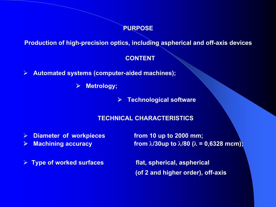
PURPOSE
Production of high-precision optics, including aspherical and off-axis devices
CONTENT
Automated systems (computer-aided machines);
Metrology;
Technological software
Machining accuracy from λ/30up to λ/80 (λ = 0,6328 mcm);
TECHNICAL CHARACTERISTICS
Diameter of workpieces from 10 up to 2000 mm;
Type of worked surfaces flat, spherical, aspherical(of 2 and higher order), off-axis
.
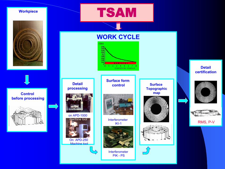
Workpiece
Control before processing
WORK CYCLE
TSAM
Detailprocessing
On APD-250Machine tool
on APD-1000machine tool
Surface form control
InterferometerIKI-1
InterferometerPIK - PS
Surface Topographic
map
RMS, P-V
Detail certification
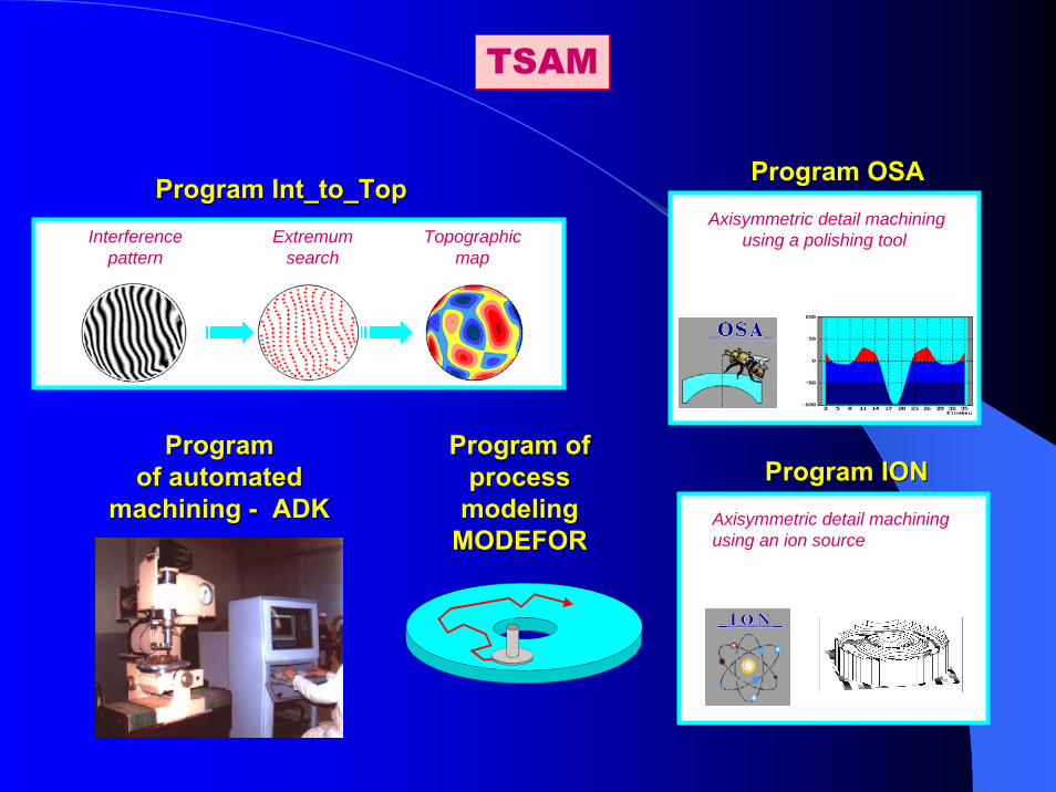
TSAM
ProgramProgram Int_to_TopInt_to_TopInterference
patternExtremum
searchTopographic
map
ProgramProgramof automated of automated
machining machining -- ADKADK
Program ofProgram ofprocessprocess
modelingmodelingMODEFORMODEFOR
ProgramProgram OSAOSAAxisymmetric detail machining
using a polishing tool
ProgramProgram IONIONAxisymmetric detail machiningusing an ion source

Automated computer-aided polishing machine APD
Basic control systemsFor polishing machine APD
Controlframe
Industrialcomputer
Drivingunit

Finishing machine APD-250
Automatic finishing machine APD-1000
Automated asphericalmirror machining

Interferometer PIKA Interferometer PIKA -- 11
Reference flat mirror
Objective
Laserλ = 0,63 mcm
optical sensor
Telescope objective
Folding mirror
Focusingobjective
Beam
sp l
itte r
Changeable objectives
Con
trol
led
surf
ace
Interference control systemsInterference control systemsSpherical surface controlSpherical surface control
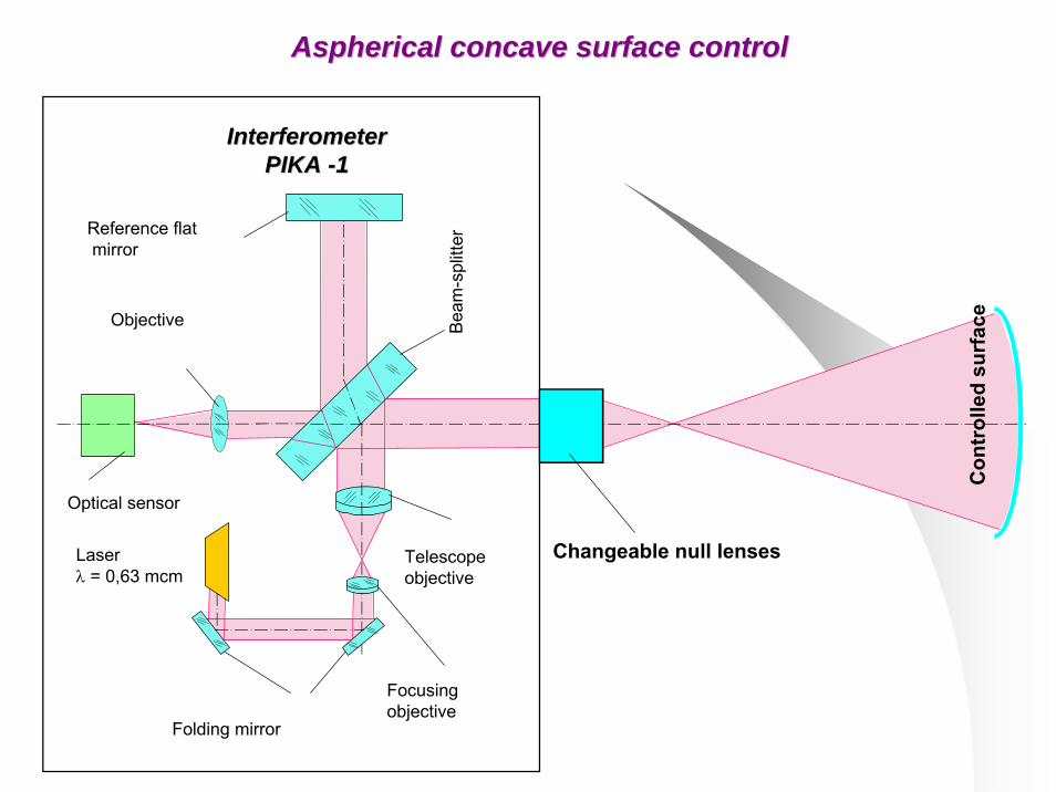
AsphericalAspherical concave surface controlconcave surface control
InterferometerInterferometerPIKA PIKA --11
Reference flatmirror
Objective
Laserλ = 0,63 mcm
Optical sensor
Telescopeobjective
Folding mirror
Focusingobjective
Beam
-sp l
itte r
Changeable null lenses
Con
trol
led
surf
ace

Flat surface controlFlat surface control
Interferometer Interferometer PIKA PIKA --11
Reference flatmirror
Objective
Laserλ = 0,63mcm
Optical sensor
Telescopeobjective
Folding mirrorОбъективфокусирующий
Beam
-sp l
itte r
Con
trol
led
surf
ace
Collimatingsystem
Collimatingsystem
D=
20 m
m
D=
100
mm D=
600
mm
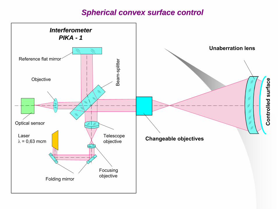
Spherical convex surface controlSpherical convex surface control
InterferometerInterferometerPIKA PIKA -- 11
Reference flat mirror
Objective
Laserλ = 0,63 mcm
Optical sensor
Telescopeobjective
Folding mirror
Focusing objective
Beam
-sp l
itte r
Unaberration lens
Con
trol
led
surf
ace
Changeable objectives

AsphericalAspherical convex surface controlconvex surface control
Reference flat mirror
Objective
Laserλ = 0,63 mcm
Optical sensor
Telescopeobjective
Folding mirror Focusingobjective
Beam
-sp l
itte r
Changeable objectives
Con
trol
led
surf
ace
Referencemirror
InterferometerInterferometerPIKA PIKA --11

Interference control systems in visible and IR ranges
Universal interference complex MIK
Control of spherical and aspherical surfaces;Wave front quality control;
In the lateral shift modeInterferometer is resistant to external effect
Working modewith reference wave front; lateral shift interference
RMS measurement λ/ 60 with reference wavefronterror λ/40 with lateral shift
Maximal aperture of controlled surface up to 1 : 3
Interferogram analysis software program Int_to_Top
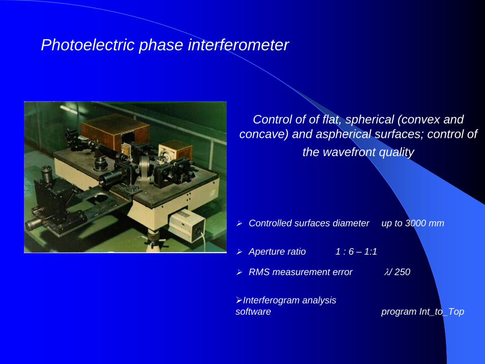
Photoelectric phase interferometer
Control of of flat, spherical (convex and concave) and aspherical surfaces; control of
the wavefront quality
Controlled surfaces diameter up to 3000 mm
RMS measurement error λ/ 250
Aperture ratio 1 : 6 – 1:1
Interferogram analysis software program Int_to_Top

Interferometer for aspherical control
Control of aspherical surfaces using an aberration compensator
Diameter of controlled surfaces from 20 mm up to 3000 mm
RMS measurement error λ/ 150
Aperture ratio 1 : 6 – 1:2
Interferogram analysis software program Int_to_Top

IR interferometer
Control of grinded surfaces
Controlled surfaces aperture 1:6 – 1:2
RMS measurement error λ/ 60
Main wave length 10,6 mcm
Measurement method amplitude
Tuning wave length 0,6 mcm

Technological mountings for optical workpieces holding,
basing and off-loading
Membrane -pneumatic mounting for workpieces up to 600 mm
(vertical testing)
Membrane - pneumatic mountingfor workpieces up to 1000 mm
(vertical testing)
Mechanical tape mounting (horizontal testing)
Up to ∅ 1000 mmUp to ∅ 600 mm
.

Technological equipment and accessory for the technology of optical coating vacuum sputtering with ion assistance
SUBSTRATE- glass (n=1,48-1,8)- crystals (n=1,8-3,0)- semiconductors
(n=3,0-4,0)- plastics
FILM-FORMINGMATERIALS:
fluorides, oxides,selenides,
rare-earth metalssulphides(n=var)
REQUIRED SPECTRAL CHARACTERISTICS
R, T, λΔ0,5/λ etc
COATINGCORRECTION
TECHNOLOGICALEQUIPEMENT:
ILO-200;the system of gas
SNA-2 puffing;
evaporators
VACUUM UNIT VU-2M:the coating deposition
process( substrate ion cleaning,
coating deposition
with ion assistance ILO-200)
TECHNOLOGICALCONTROL:multiwave
spectrophotometer
FINISHEDPRODUCTS
REQUIRED SPECTRAL
CHARACTERISTICSOBTAINING
ProgramPLENKA
Coating design and synthesis, adapted for the use of ILO-
200 source, the photometric control process calculation
BASIC DATA:
.

ION-BEAM SOURCE ILO - 200

Masks set for ion machining
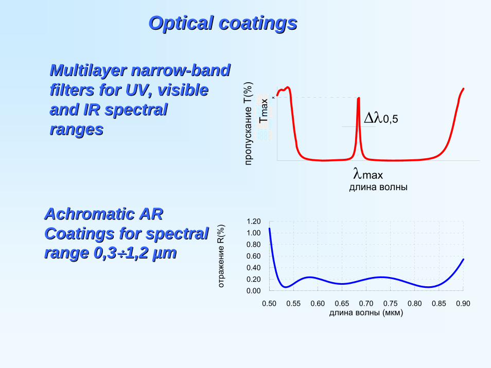
OpticalOptical coatingscoatings
Multilayer narrowMultilayer narrow--band band filters for UV, visiblefilters for UV, visibleand IR spectral and IR spectral rangesranges
длина волны
пропускание Т(
%)
Tmax
Δλ0,5
λmax
Тmax
Achromatic AR Achromatic AR Coatings for spectral Coatings for spectral range 0,3range 0,3÷÷1,2 1,2 µµmm
0.50 0.55 0.60 0.65 0.70 0.75 0.80 0.85 0.90длина волны (мкм)
0.000.200.400.600.801.001.20
отражение
R(%
)
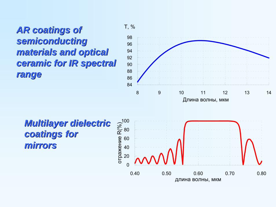
AR coatings of AR coatings of semiconductingsemiconductingmaterials and optical materials and optical ceramic for IR spectral ceramic for IR spectral rangerange
8 9 10 11 12 13 14
8486889092949698
Длина волны, мкм
Т, %
Multilayer dielectric Multilayer dielectric coatingscoatings for for mirrorsmirrors
0.40 0.50 0.60 0.70 0.80длина волны, мкм
0
20
40
60
80
100отраже
ние
R(%
)

Optical work bay for automated machining
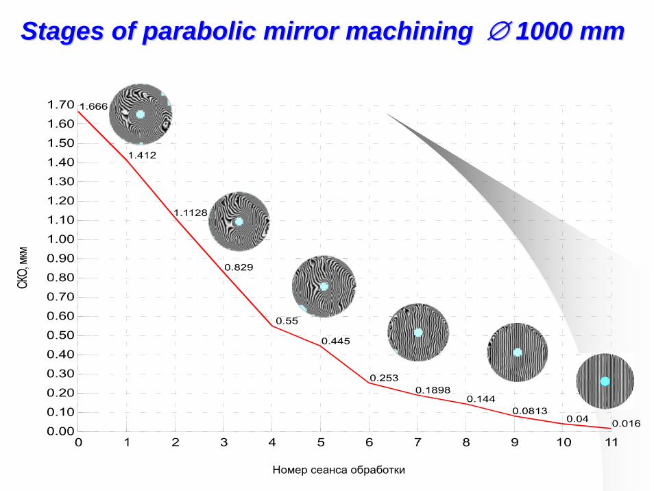
Номер сеанса обработки
Stages of parabolic mirror machining Stages of parabolic mirror machining ∅∅ 1000 mm1000 mm
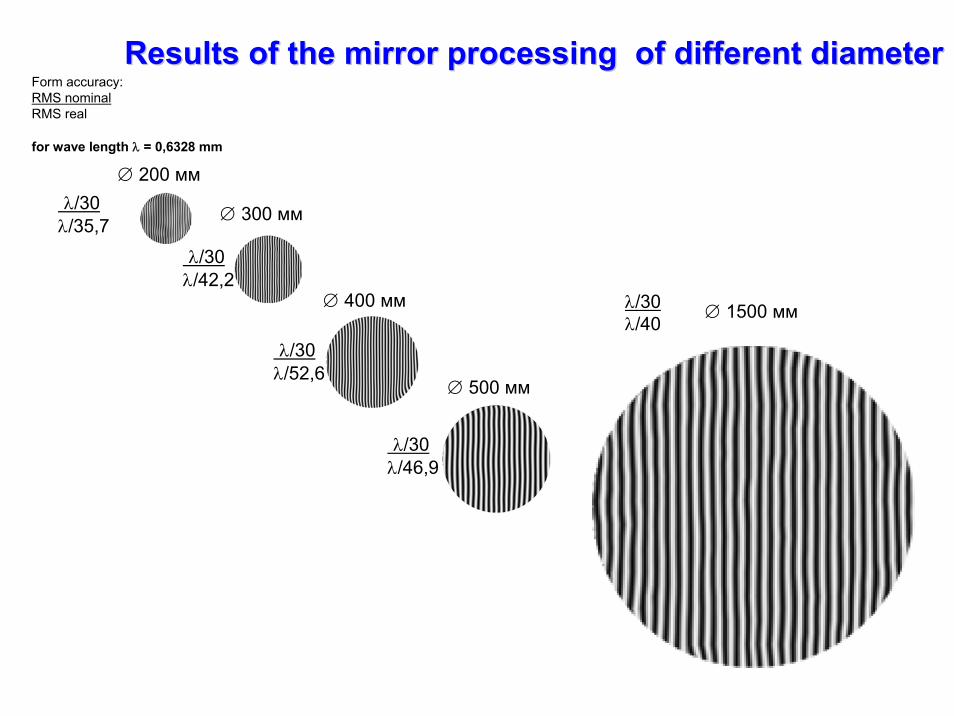
Results of the mirror processing of different diameterResults of the mirror processing of different diameter
λ/30λ/35,7
∅ 200 мм
λ/30λ/46,9
∅ 500 мм
λ/30λ/40
∅ 1500 мм
∅ 300 мм
λ/30λ/42,2
∅ 400 мм
λ/30λ/52,6
Form accuracy:RMS nominalRMS real
for wave length λ = 0,6328 mm

Optical details produced with computer technologies
Hyperbolic mirror(Zerodur, diameter = 1540 mm,
axial thickness = 300 mm)
RMS=0,015 мкм= λ/42 P-V=0,075 мкм= λ/8,4

RMS=0,025 мкм= λ/25 P-V=0,15 мкм= λ/4,21
Thin adaptive mirror(quartz, diameter = 1550 mm,
axial thickness = 45 mm)
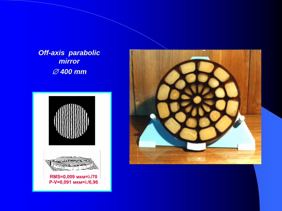
Off-axis parabolic mirror
∅ 400 mm
RMS=0,009 мкм=λ/70P-V=0,091 мкм=λ/6,96

RMS=0,06 мкм=λ/11P-V=0,31 мкм= λ/2
Central and off-axis elements of parabolic mirror
(off-axis parameter = 375 mm,diameter of circumcircle = 420 mm)
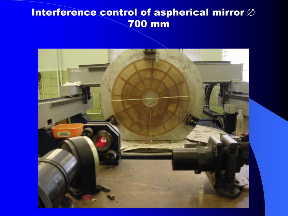
Interference control of aspherical mirror ∅700 mm

Adaptive mirror ∅ 3000 mm
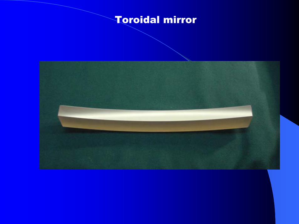
Toroidal mirror
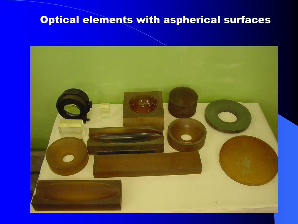
Optical elements with aspherical surfaces

Mirror collimator ∅ 700 mm

Lightweight parabolic mirrors
D = 250 mmD = 400 mm

Silicon carbide aspherical mirror ∅ 250 mm

Aspherical reflector ∅ 1000 mm

Radiometer asphericalcomponents
Radiometer(optical-mechanical
system)

Optical element with two aspherical surfaces glued