computer...
TRANSCRIPT

Topics covered:Course outline and scheduleIntroduction
Computer Organization
Unit 2. Machine Instructions and Programs
13.12.17
Dr e v prasad

2Chapter 2 - Machine Instructions & Programs
Chapter 2. Machine Instructions and Programs

Objectives
Machine instructions and program execution, including branching and subroutine call and return operations.
Number representation and addition/subtraction in the 2’s-complement system.
Addressing methods for accessing register and memory operands.
Assembly language for representing machine instructions, data, and programs.
Program-controlled Input/output operations.
3Chapter 2 - Machine Instructions & Programs

Number, Arithmetic Operations, and Characters
4Chapter 2 - Machine Instructions & Programs

Signed Integer
3 major representations:
Sign and magnitude
One’s complement
Two’s complement
Assumptions:
4-bit machine word
16 different values can be represented
Roughly half are positive, half are negative
5Chapter 2 - Machine Instructions & Programs

Sign and Magnitude Representation
0000
0111
0011
1011
1111
1110
1101
1100
1010
1001
1000
0110
0101
0100
0010
0001
+0
+1
+2
+3
+4
+5
+6
+7-0
-1
-2
-3
-4
-5
-6
-7
0 100 = + 4
1 100 = - 4
+
-
High order bit is sign: 0 = positive (or zero), 1 = negativeThree low order bits is the magnitude:
0 (000) thru 7 (111) Number range for n bits = (+/- ) 2n-1 -1Two representations for 0
6Chapter 2 - Machine Instructions & Programs

One’s Complement Representation
Subtraction implemented by addition & 1's complement
Still two representations of 0! This causes some problems
Some complexities in addition
perform binary addition, then add in an end-around carry value.
0000
0111
0011
1011
1111
1110
1101
1100
1010
1001
1000
0110
0101
0100
0010
0001
+0
+1
+2
+3
+4
+5
+6
+7-7
-6
-5
-4
-3
-2
-1
-0
0 100 = + 4
1 011 = - 4
+
-
7Chapter 2 - Machine Instructions & Programs

Two’s Complement Representation
Only one representation for 0
One more negative number than positive number
0000
0111
0011
1011
1111
1110
1101
1100
1010
1001
1000
0110
0101
0100
0010
0001
+0
+1
+2
+3
+4
+5
+6
+7-8
-7
-6
-5
-4
-3
-2
-1
0 100 = + 4
1 100 = - 4
+
-
like 1's compexcept shiftedone positionclockwise
8Chapter 2 - Machine Instructions & Programs
Notation Min Max Unsigned: 0 255 One's Comp:-127 +127 Two's Comp:-128 +127

Binary, Signed-Integer Representations
0
0
0
0
0
0
0
0
1
1
1
1
1
1
1
1
0
0
0
0
0
0
0
0
1
1
1
1
1
1
1
1
1
1
0
0
1
1
0
0
0
0
1
1
0
0
1
1
1
0
1
0
1
0
1
0
0
1
0
1
0
1
0
1
1+
1-
2+
3+
4+
5+
6+
7+
2-
3-
4-
5-
6-
7-
8-
0+
0-
1+
2+
3+
4+
5+
6+
7+
0+
7-
6-
5-
4-
3-
2-
1-
0-
1+
2+
3+
4+
5+
6+
7+
0+
7-
6-
5-
4-
3-
2-
1-
b3
b2b
1b
0
Sign andmagnitude 1's complement 2's complement
B Values represented
Figure 2.1. Binary, signed-integer representations. 9

Addition and Subtraction – 2’s Complement
4
+ 3
7
0100
0011
0111
-4
+ (-3)
-7
1100
1101
11001
4
- 3
1
0100
1101
10001
-4
+ 3
-1
1100
0011
1111
If carry-in to the high order bit = carry-out then ignorecarryif carry-in differs fromcarry-out then overflow
Simpler addition scheme makes twos complement the most commonchoice for integer number systems within digital systems
10Chapter 2 - Machine Instructions & Programs

2’s-Complement Add and Subtract Operations
1 1 0 10 1 1 1
0 1 0 0
0 0 1 01 1 0 0
1 1 1 0
0 1 1 01 1 0 1
0 0 1 1
1 0 0 10 1 0 1
1 1 1 0
1 0 0 11 1 1 1
1 0 0 0
0 0 1 00 0 1 1
0 1 0 1
4+( )
2-( )
3+( )
2-( )
8-( )
5+( )
+
+
+
+
+
+
1 1 1 0
0 1 0 01 0 1 0
0 1 1 11 1 0 1
0 1 0 0
6-( )
2-( )
4+( )
3-( )
4+( )
7+( )
+
+(b)
(d)1 0 1 11 1 1 0
1 0 0 1
1 1 0 11 0 0 1
0 0 1 00 1 0 0
0 1 1 00 0 1 1
1 0 0 11 0 1 1
1 0 0 10 0 0 1
0 0 1 01 1 0 1
0 1 0 1
0 0 1 00 0 1 1
5-( )
2+( )3+( )
5+( )
2+( )4+( )
2-( )
7-( )
3-( )7-( )
6+( )3+( )
1+( )
7-( )5-( )
7-( )
2+( )3-( )
+
+
-
-
-
-
-
-
(a)
(c)
(e)
(f)
(g)
(h)
(i)
(j)
Figure 2.4. 2's-complement Add and Subtract operations. 11

Overflow - Add two positive numbers to get a negative number or two negative numbers to get a positive number
5 + 3 = -8 -7 - 2 = +7
0000
0001
0010
0011
1000
0101
0110
0100
1001
1010
1011
1100
1101
0111
1110
1111
+0
+1
+2
+3
+4
+5
+6
+7-8
-7
-6
-5
-4
-3
-2
-1
0000
0001
0010
0011
1000
0101
0110
0100
1001
1010
1011
1100
1101
0111
1110
1111
+0
+1
+2
+3
+4
+5
+6
+7-8
-7
-6
-5
-4
-3
-2
-1
12Chapter 2 - Machine Instructions & Programs
Overflow in 2’s-Complement Addition

Overflow Conditions
5
3
-8
0 1 1 10 1 0 1
0 0 1 1
1 0 0 0
-7
-2
7
1 0 0 01 0 0 1
1 1 0 0
1 0 1 1 1
5
2
7
0 0 0 00 1 0 1
0 0 1 0
0 1 1 1
-3
-5
-8
1 1 1 11 1 0 1
1 0 1 1
1 1 0 0 0
Overflow Overflow
No overflow No overflow
Overflow when carry-in to the high-order bit does not equal carry out
13Chapter 2 - Machine Instructions & Programs

Chapter 2 - Machine Instructions & Programs 14
2’s-Complement Addition-examples 1

Chapter 2 - Machine Instructions & Programs 15
2’s-Complement Addition-examples 2

Sign Extension
Task:
Given w-bit signed integer x
Convert it to w+k-bit integer with same value
Rule:
Make k copies of sign bit:
X = xw–1 ,…, xw–1 , xw–1 , xw–2 ,…, x0
k copies of MSB
• • •X
X • • • • • •
• • •
w
wk16Chapter 2 - Machine Instructions & Programs

Sign Extension Example
short int x = 15213;int ix = (int) x; short int y = -15213;int iy = (int) y;
Decimal Hex Binaryx 15213 3B 6D 00111011 01101101
ix 15213 00 00 C4 92 00000000 00000000 00111011 01101101
y -15213 C4 93 11000100 10010011
iy -15213 FF FF C4 93 11111111 11111111 11000100 10010011
17Chapter 2 - Machine Instructions & Programs

18Chapter 2 - Machine Instructions & Programs
Memory Locations, Addresses, and Operations

Memory Location, Addresses, and Operation
Memory consists of many millions of storage cells, each of which can store 1 bit.
Data is usually accessed in n-bit groups. n is called word
length.
second word
first word
Figure 2.5. Memory words.
nbits
last word
i th word
•••
•••
19Chapter 2 - Machine Instructions & Programs

Memory Location, Addresses, and Operation
32-bit word length example
(b) Four characters
charactercharactercharacter character
(a) A signed integer
Sign bit: for positive numbersfor negative numbers
ASCIIASCIIASCIIASCII
32 bits
8 bits 8 bits 8 bits 8 bits
b31 b30 b1 b0
b31 0=
b31 1=
• • •
20

Memory Location, Addresses, and Operation
To retrieve information from memory, either for one word or one byte (8-bit), addresses for each location are needed.
A k-bit address memory has 2k memory locations, namely 0 to (2k-1), called memory space.
24-bit memory: 224 = 16,777,216 = 16M (1M=220)
32-bit memory: 232 = 4G (1G=230)
1K (kilo)=210
1T (tera)=240
1P (peta)=250
21Chapter 2 - Machine Instructions & Programs

Memory Location, Addresses, and Operation
It is impractical to assign distinct addresses to individual bit locations in the memory.
The most practical assignment is to have successive addresses refer to successive byte locations in the memory –byte-addressable memory.
Byte locations have addresses 0, 1, 2, … If word length is 32 bits, they successive words are located at addresses 0, 4, 8,…
22Chapter 2 - Machine Instructions & Programs

Big-Endian and Little-Endian Assignments
Figure 2.7. Byte and word addressing.
Big-Endian: lower byte addresses are used for the most significant bytes of the word
Little-Endian: opposite ordering. lower byte addresses are used for the less significant bytes of the word
23
2k
4- 2k
3- 2k
2- 2k
1- 2k
4-2k
4-
0 1 2 3
4 5 6 7
00
4
2k
1- 2k
2- 2k
3- 2k
4-
3 2 1 0
7 6 5 4
Byte addressByte address
(a) Big-endian assignment (b) Little-endian assignment
4
word address
•••
•••

Memory Location, Addresses, and Operation
Address ordering of bytes
Word alignment Words are said to be aligned in memory if they begin
at a byte addr. that is a multiple of the num of bytes in a word.• 16-bit word: word addresses: 0, 2, 4,….• 32-bit word: word addresses: 0, 4, 8,….• 64-bit word: word addresses: 0, 8, 16,….
Access numbers, characters, and character strings
24Chapter 2 - Machine Instructions & Programs

Memory Operation
Load (or Read or Fetch)
Copy the content. The memory content doesn’t change.
Address – Load
Registers can be used
Store (or Write)
Overwrite the content in memory
Address and Data – Store
Registers can be used
25Chapter 2 - Machine Instructions & Programs

26Chapter 2 - Machine Instructions & Programs
Instructions and Instruction Sequencing
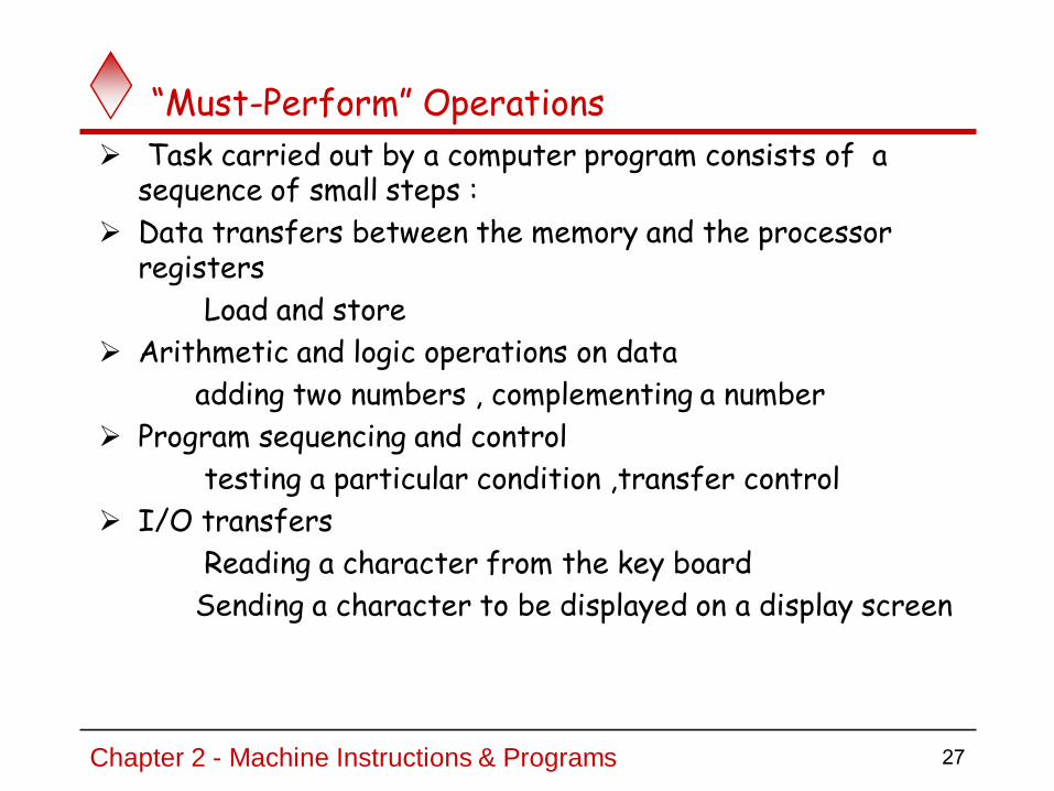
“Must-Perform” Operations
Task carried out by a computer program consists of a sequence of small steps :
Data transfers between the memory and the processor registers
Load and store
Arithmetic and logic operations on data
adding two numbers , complementing a number
Program sequencing and control
testing a particular condition ,transfer control
I/O transfers
Reading a character from the key board
Sending a character to be displayed on a display screen
27Chapter 2 - Machine Instructions & Programs

Register Transfer Notation
A symbolic notation to describe the microoperation transfers among registers.
register transfer language (RTL) is a kind of intermediate representation (IR) that is very close to assembly language, such as that which is used in a compiler.
It is used to describe data flow at the register-transfer level of an architecture.
Identify a location by a symbolic name standing for its hardware binary address (LOC, R0,…)
Contents of a location are denoted by placing square brackets around the name of the location
(R1←[LOC], R3 ←[R1]+[R2]) Representation of a (conditional) transfer
P: R2 ← R1
Register Transfer Notation (RTN)
28Chapter 2 - Machine Instructions & Programs

Register Transfer.
t t+1
Clock
Load
Transfer occurs here
Synchronized with the clock
n
Clock
R1
R2Control
CircuitLoadP
Hardware implementation of a controlled transfer: P: R2 ← R1
Block diagram:
Timing diagram

Assembly Language Notation
Represent machine instructions and programs.
Move LOC, R1 = R1←[LOC]
Add R1, R2, R3 = R3 ←[R1]+[R2]
30Chapter 2 - Machine Instructions & Programs

CPU Organization
Single Accumulator
Result usually goes to the Accumulator
Accumulator has to be saved to memory quite often
General Register
Registers hold operands thus reduce memory traffic
Register bookkeeping
Stack
Operands and result are always in the stack
31Chapter 2 - Machine Instructions & Programs
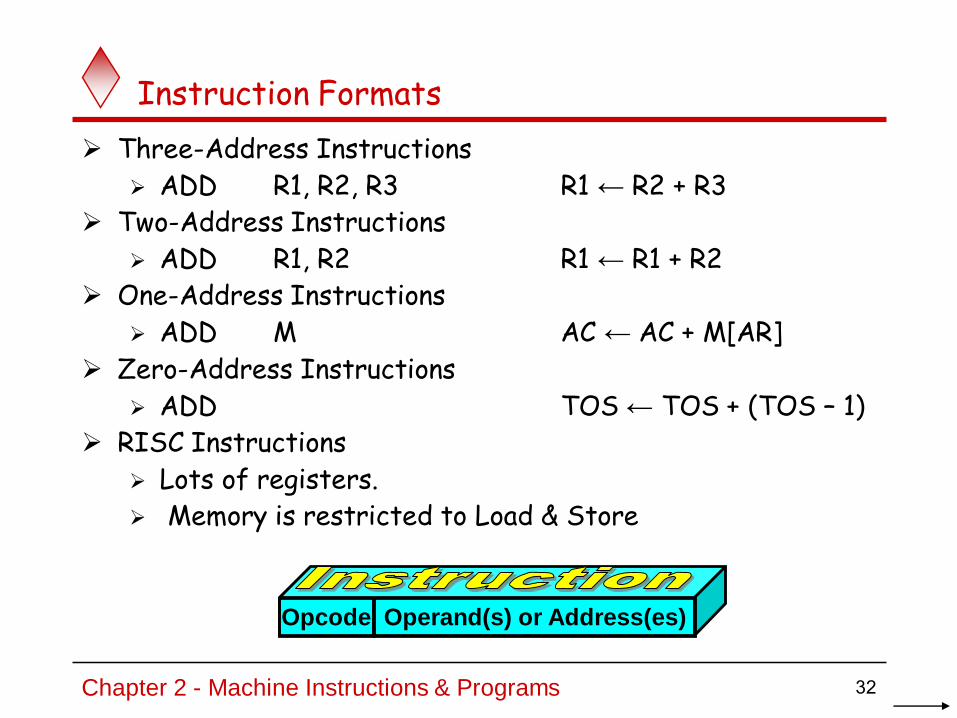
Instruction Formats
Three-Address Instructions
ADD R1, R2, R3 R1 ← R2 + R3
Two-Address Instructions
ADD R1, R2 R1 ← R1 + R2
One-Address Instructions
ADD M AC ← AC + M[AR]
Zero-Address Instructions
ADD TOS ← TOS + (TOS – 1)
RISC Instructions
Lots of registers.
Memory is restricted to Load & Store
Opcode Operand(s) or Address(es)
32Chapter 2 - Machine Instructions & Programs

three address instruction Three explicit operands
per instruction
Operands specify source, destination, and result
Directly operate on memory variables or registers
Use Temp variables
Operations are with the memory variables/two (one) memory variable(s) and one (two) register(s)
12
5
20
data
27
10000
10001
10002
10003
Memory
CPU
5R0
37R1
32R2
A
B
C
D
D = A+B+C
Note : ADD R2,R0,R1 means R2 = R0+R1

two address instruction Two explicit operands per
instruction
Result overwrites one of the operands
Operands known as source and destination
Works well for instructions such as memory copy
Uses Move (MOV) instruction
MOV instruction transfers the operands between memory and processor registers
Operations are in the registers / one in register and one in memory
D = A+B+C
Note : ADD R0,R1 means R0 = R0+R1
12
5
20
data
27
10000
10001
10002
10003
Memory
CPU
5R0
37R1
32R2
A
B
C
D

One address instruction
One explicit operand per instruction
Second operand is implicit – Always found in hardware register – Known as accumulator (reg A)
AC contains the result of all operations.
Uses Load (LDA) and Store (STA) to access memory
Operations are in the registers/ one can be in memory
12
5
20
data
27
10000
10001
10002
10003
Memory
CPU
A
B
C
D
5ACC
Note : ADD [10001] means Acc = Acc + [10001]
D = A+B+C

Instruction Formats
Example: Evaluate (A+B) (C+D)
Three-Address
1. ADD R1, A, B ; R1 ← M[A] + M[B]
2. ADD R2, C, D ; R2 ← M[C] + M[D]
3. MUL X, R1, R2 ; M[X] ← R1 R2
Three-address instruction formats can use each address field to specify either a processor register or a memory operand.
It is assumed that the computer has two processor registers, R1 and R2. The symbol M [X] denotes the operand at memory address symbolized by A.
The advantage of the three-address format is that it results in short programs when evaluating arithmetic expressions.
The disadvantage is that the binary-coded instructions require too many bits to specify three addresses.
36Chapter 2 - Machine Instructions & Programs

Instruction Formats
Example: Evaluate (A+B) (C+D)
Two-Address
1. MOV R1, A ; R1 ← M[A]
2. ADD R1, B ; R1 ← R1 + M[B]
3. MOV R2, C ; R2 ← M[C]
4. ADD R2, D ; R2 ← R2 + M[D]
5. MUL R1, R2 ; R1 ← R1 R2
6. MOV X, R1 ; M[X] ← R1
each address field can specify either a processor register or a memory word.
MOV instruction moves or transfers the operands to and from memory and processor registers .
The first symbol listed in an instruction is assumed to be both a source and the destination
37Chapter 2 - Machine Instructions & Programs

Instruction Formats
Example: Evaluate (A+B) (C+D)
One-Address
1. LOAD A ; AC ← M[A]
2. ADD B ; AC ← AC + M[B]
3. STORE T ; M[T] ← AC
4. LOAD C ; AC ← M[C]
5. ADD D ; AC ← AC + M[D]
6. MUL T ; AC ← AC M[T]
7. STORE X ; M[X] ← AC
One-address instructions use an implied accumulator (AC) register for all data manipulation.
All operations are done between the AC register and a memory operand
Uses LOAD and STORE instructions to transfer the operands between memory and processor registers.
38Chapter 2 - Machine Instructions & Programs

Instruction FormatsExample: Evaluate (A+B) (C+D)
Zero-Address
1. PUSH A ; TOS ← A
2. PUSH B ; TOS ← B
3. ADD ; TOS ← (A + B)
4. PUSH C ; TOS ← C
5. PUSH D ; TOS ← D
6. ADD ; TOS ← (C + D)
7. MUL ; TOS ← (C+D)(A+B)
8. POP X ; M[X] ← TOS
A stack-organized computer does not use an address field for the instructions ADD and MUL.
The PUSH and POP instructions, need an address field to specify the operand that communicates with the stack.
39Chapter 2 - Machine Instructions & Programs

Instruction Formats
Example: Evaluate (A+B) (C+D)
RISC
1. LOAD R1, A ; R1 ← M[A]
2. LOAD R2, B ; R2 ← M[B]
3. LOAD R3, C ; R3 ← M[C]
4. LOAD R4, D ; R4 ← M[D]
5. ADD R1, R1, R2 ; R1 ← R1 + R2
6. ADD R3, R3, R4 ; R3 ← R3 + R4
7. MUL R1, R1, R3 ; R1 ← R1 R3
8. STORE X, R1 ; M[X] ← R1
Uses registers fro all operations
Uses LOAD and STORE instructions for operand transfer.
40Chapter 2 - Machine Instructions & Programs

Chapter 2 - Machine Instructions & Programs 41
Practice on the following expressionY=(A-B)/(C+D x E)

Chapter 2 - Machine Instructions & Programs 42
Example: Y=(A-B)/(C+D x E)
ThreeAddresses: SUB Y, A, B MPY T, D, E ADD T, T, C DIV Y, Y, T
Two Addresses MOV Y, A SUB Y, B MOV T, D MPY T,E ADD T,C DIV Y, T
One Addresses: LOAD DMPY EADD C STOR Y LOAD A SUB B DIV Y
Stack (0 address) Push A Push B SUB Push C Push D Push EMPY ADD DIVPop Y

Using Registers
Registers are faster
Shorter instructions
The number of registers is smaller (e.g. 32 registers need 5 bits)
Potential speedup
Minimize the frequency with which data is moved back and forth between the memory and processor registers.
43Chapter 2 - Machine Instructions & Programs

Instruction Execution and Straight-Line Sequencing
R0,C
B,R0
A,R0
Movei + 8
Begin execution here Movei
ContentsAddress
C
B
A
the programData for
segmentprogram3-instruction
Addi + 4
Figure 2.8. A program for C ¬ [A] + [B].
Assumptions:- One memory operand
per instruction- 32-bit word length- Memory is byte
addressable- Full memory address
can be directly specifiedin a single-word instruction
Two-phase procedure-Instruction fetch-Instruction execute
44Chapter 2 - Machine Instructions & Programs

Branching
Figure 2.9. A straight-line program for adding n numbers.
NUM n
NUM2
NUM1
R0,SUM
NUM n,, R0
NUM3,R0
NUM2,R0
NUM1,R0
Add
Add
Move
SUM
i
Move
Add
i 4n+
i 4n 4-+
i 8+
i 4+
•••
•••
•••
45Chapter 2 - Machine Instructions & Programs

Branching
Figure 2.10. Using a loop to add nnumbers.
Program
NUM
NUM2
NUM1
LOOP
loop
N
SUM
R1,NMove
n
R0,SUM
R1"Next" number to R0
LOOP
Decrement
Move
Determine address of"Next" number and add
n
R0Clear
Branch>0
•••
•••
Branch target
Conditional branch
46Chapter 2 - Machine Instructions & Programs

Condition code flags
N /SF (negative/sign)
ZF (zero)
VF (overflow)
CF (carry)
PF (Parity Flag)
AF (Auxiliary Flag)
Condition code register / status register
47Chapter 2 - Machine Instructions & Programs
Status flags (CF, PF, AF, ZF, SF, OF)
Set to represent the result of certain operations
Used to control conditional jump instructions
Different instructions affect different flags

Chapter 2 - Machine Instructions & Programs 48
Status Flags Carry (CF) : carry or borrow at MSB in add or subtract
last bit shifted outParity (PF) : low byte of result has even parity (PF)Auxiliary (AF) : carry or borrow at bit 3Zero (ZF): result is 0Sign (SF): result is negativeOverflow (OF/VF): signed overflow occurred during add or subtract
1) CF = 1 if there is a carry out from the MSB on addition, or there is a borrow into the MSB on subtraction
CF = 0 otherwiseCF is also affected by shift and rotate instructions
2) PF = 1 if the low byte of a result has an even number of ones (even parity)PF = 0 otherwise (odd parity)
3) AF = 1 if there is a carry out from bit 3 on addition, or there is a borrow into the bit 3 on subtractionAF = 0 otherwise
AF is used in binary-coded decimal (BCD) operations.
Condition Codes/Flags

Chapter 2 - Machine Instructions & Programs 49
4) ZF = 1 for a zero resultZF = 0 for a non-zero result
5) SF = 1 if the MSB of a result is 1; it means the result is negative if you are giving a signed interpretation
SF = 0 if the MSB is 06) OF/VF = 1 if signed overflow occurred
OF/VF = 0 otherwise(Signed) Overflow Can only occur when adding numbers of the same sign (subtracting with different signs)Detected when carry into MSB is not equal to carry out of MSB
Easily detected because this implies the result has a different sign than the sign of the operands.
Programs can ignore the Flags!

Chapter 2 - Machine Instructions & Programs 50
10010110
+ 10100011
00111001
Carry in = 0, Carry out = 1
Neg+Neg=Pos
Signed overflow occurred : OF/VF= 1 (set)
00110110
+ 01100011
10011001
Carry in = 1, Carry out = 0
Pos+Pos=Neg
Signed overflow occurred : OF/VF = 1 (set)
Signed Overflow (Example )
Example 1
Example 2

Chapter 2 - Machine Instructions & Programs 51
10010110+ 0110001111111001
Carry in = 0, Carry out = 0Neg+Pos=NegNo Signed overflow occurred : OF /VF= 0 (clear)
10010110+ 1111001110001001
Carry in = 1, Carry out = 1Neg+Neg=NegNo Signed overflow occurred : OF /VF= 0 (clear)
Examples of No Signed Overflow
Example 3
Example 4

Chapter 2 - Machine Instructions & Programs 52
The carry flag is used to indicate if an unsigned operation overflowed
•The processor only adds or subtracts - it does not care if the data is signed
or unsigned!10010110
+ 11110011
10001001
Carry out = 1
Unsigned overflow occurred : CF = 1 (set)
Unsigned Overflow (Example)
Example 5

Conditional Branch Instructions
Example:
A: 1 1 1 1 0 0 0 0
B: 0 0 0 1 0 1 0 0
A: 1 1 1 1 0 0 0 0
+(−B): 1 1 1 0 1 1 0 0
1 1 0 1 1 1 0 0
C = 1
S = 1
V = 1
Z = 0
53Chapter 2 - Machine Instructions & Programs
A=0
D7 D6 D5 D4 D3 D2 D1 D0

Status Bits
ALU
V Z S C
Zero Check
Cn
Cn-1
Fn-1
A B
F
54Chapter 2 - Machine Instructions & Programs
ADD and SUB - all flags affected
INC and DEC - all except CF

Addressing Modes
55Chapter 2 - Machine Instructions & Programs
To give programming versatility to the user by providing such facilities as pointers to Memory, counters for loop control, indexing of data, and program relocation .
To reduce the number of bits in the addressing field of the instruction.
The availability of the addressing modes gives the experienced assembly language programmer flexibility for writing programs that are more efficient with respect to the number of instructions and execution time.
Why use of use addressing mode techniques ?
The different ways in which the operand address (registers/memory) is specified in an instruction are referred to as addressing modes.
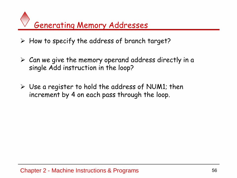
Generating Memory Addresses
How to specify the address of branch target?
Can we give the memory operand address directly in a single Add instruction in the loop?
Use a register to hold the address of NUM1; then increment by 4 on each pass through the loop.
56Chapter 2 - Machine Instructions & Programs

Addressing Modes
Implied
AC is implied in “ADD M[AR]” in “One-Address” instr.
TOS is implied in “ADD” in “Zero-Address” instr.
Immediate The operand is given explicitly in the instruction
The use of a constant in “MOV R1, 5”, i.e. R1 ← 5
Register
Indicate which register holds the operand
The operand is the contents of a processor register; the name
(address) of the register is given in the instruction.
Effective address (EA) = R
MOV R1, R2
Opcode Mode ...
57Chapter 2 - Machine Instructions & Programs

Addressing Modes
Register Indirect
Indicate the register that holds the number of the register that holds the operand
MOV R1, (R2) or MOV R1, (LOC)
Autoincrement / Autodecrement
Access & update in 1 instr.
Direct Address (ABSOLUTE MODE)
Use the given address to access a 300
memory location.
Effective address (EA) = address field (A)
The operand is in a memory location;
the address of this location is given explicitly in the instruction
e.g. ADD A
.
R1
R2 = 300
5
58Chapter 2 - Machine Instructions & Programs

Addressing Modes
Indirect Address
Indicate the memory location that holds the address of the memory location that holds the data
The register or memory
location that contains the address of an
operand is called a pointer.
EA= pointer
EA = (A)
AR = 101
100
101
102
103
104
0 1 0 4
1 1 0 A
59Chapter 2 - Machine Instructions & Programs
The effective address of the operand is the contents of a register or memory location whose address appears in the instruction.

100
101
102
103
104
0
1
2
Addressing Modes
Relative Address
EA = PC + Relative Addr
AR = 100
1 1 0 A
PC = 2
+
Could be Positive or Negative
(2’s Complement)
60Chapter 2 - Machine Instructions & Programs
Addressing Modes
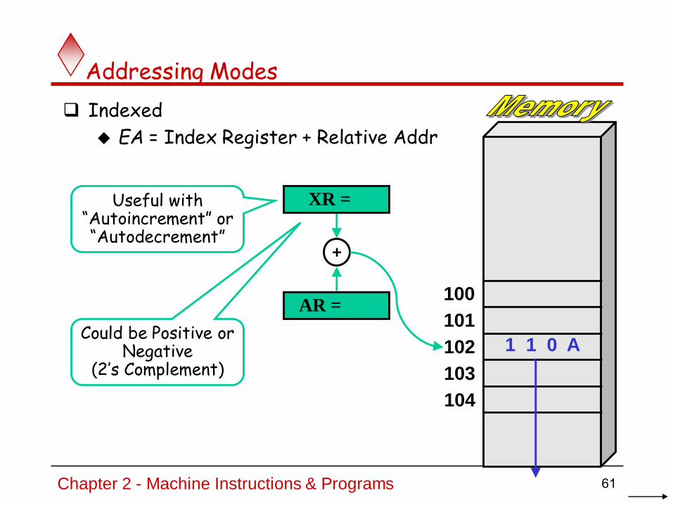
Indexed
EA = Index Register + Relative Addr
100
101
102
103
104
AR = 100
1 1 0 A
XR = 2
+
Could be Positive or Negative
(2’s Complement)
Useful with “Autoincrement” or “Autodecrement”
61Chapter 2 - Machine Instructions & Programs

Addressing Modes
Base Register
EA = Base Register + Relative Addr
100
101
102
103
104
BR = 100
0 0 0 A
AR = 2
+
Could be Positive or Negative
(2’s Complement)
Usually points to the beginning of
an array
0 0 0 5
0 0 1 2
0 1 0 7
0 0 5 9
62Chapter 2 - Machine Instructions & Programs

1. Immediate Addressing Mode
The operand is specified with in the instruction.
Operand itself is provided in the instruction rather than its address
Move Immediate
MVI A , 15h ; A ←15 H ; 15 h is the immediate operand
Add Immediate
ADI 3Eh ; A ← A + 3E H; 3E h is the immediate operand

2. Register Addressing Mode
The operand is specified with in one of the processor registers.
Instruction specifies the register in which the operand is
stored.
Move
; Here A is the operand specified MOV C , A C ← A
Add
ADD B ; A ← A + B

3. Register Indirect Addressing Mode
The instruction specifies the register in which the memory
address of operand is placed.
Move AMOV A , M ← [[H][L]]
It moves the data from memory location specified by HL registerpair to A

EX 1.Register Indirect Addressing Mode
MOV A , M A ← [[H][L]]
It moves the data from memory location specified by HL register pair to A.
Before After
2807
2806
2805
2804
2803
2802
2801
2800
2807
2806
2805
2804
2803
2802
2801
2800
A A
H H
L L
A ← [2805] A ← A9
0505
2828
A9
A9A9
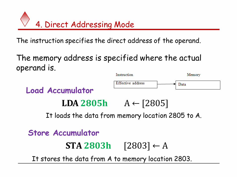
4. Direct Addressing Mode
The instruction specifies the direct address of the operand.
The memory address is specified where the actual operand is.
Load Accumulator
LDA 2805h A ← [2805]
It loads the data from memory location 2805 to A.
Store Accumulator
STA 2803h [2803] ← A
It stores the data from A to memory location 2803.

Ex 1.Direct Addressing Mode
LDA 2805 H A ← [2805]
It loads the data from the memory location 2805 H to A
Before After
2807
2806
2805
2804
2803
2802
2801
2800
2807
2806
2805
2804
2803
2802
2801
2800
A A
A ← [2805] A ← 5C
5C
5C5C

Ex 2.Direct Addressing Mode
STA 2803h [2803] ← A
It copies the data stored in Register A in memory location 2803.
Before After
2807
2806
2805
2804
2803
2802
2801
2800
2807
2806
2805
2804
2803
2802
2801
2800
A A
[2803] ← A [2803] ← 9B
9B9B
9B

5. Indirect Addressing Mode
The instruction specifies the indirect address where the
effective address of the operand is placed.
The memory address is specified where the actual address of
operand is placed.
MOV A, 2802 H ; A ← [[2802]]
It moves the data from memory location specified by thelocation 2802 to A.

Ex. Indirect Addressing Mode
MOV A, [2802]h A ← [[280 2]]
It transfer the data from memory specified memory location to A
Before After
2807
2806
2805
2804
2803
2802
2801
2800
2807
2806
2805
2804
2803
2802
2801
2800
A A
A ← [[2806]] A ← FF
FFFF
06
28
FF
06
28

6. Implied Addressing Mode
It is also called inherent addressing mode.
The operand is implied by the instruction.The operand is hidden/fixed inside the instruction.
Complement Accumulator :CMA
(Here accumulator A is implied by the instruction)
Complement Carry Flag : CMC
(Here Flags register is implied by the instruction)
Set Carry Flag : STC

7. Relative Addressing Mode
In relative addressing mode, contents of Program Counter PC is
added to address part of instruction to obtain effective address.
The address part of the instruction is called as offset and it can
+ve or –ve.
When the offset is added to the PC the resultant number is the
memory location where the operand will be placed.
X(PC) – note that X is a signed numberBranch > 0 LOOP
This location is computed by specifying it as an offset from the current value of PC.
Branch target may be either before or after the branch instruction, the offset is given as a singed num.

Ex. Relative Addressing mode
2807
2806
2805
2804
2803
2802
2801
2800
2807
2806
2805
2804
2803
2802
2801
2800
Actual OperandOffset = 04h
PC
Effective address of operand = PC + 01 + offsetEffective address of operand = 2801 + 01 + 04Effective address of operand = 2806h
2801
22
FF
6D
59
08
2E
F3
9F
22
FF
6D
59
08
2E
F3
9F

Ex.Relative Addressing
Actual Operand2807
2806
2805
2804
2803
2802
2801
2800
2807
2806
2805
2804
2803
2802
2801
2800
Offset = 03h
PC
Effective address of operand = PC + 01 + offsetEffective address of operand = 2803 + 01 + 03Effective address of operand = 2807h
2803
22
FF
6D
59
08
2E
F3
9F
22
FF
6D
59
08
2E
F3
9F

8. Indexed Addressing Mode
In index addressing mode, contents of Index register is added to
address part of instruction to obtain effective address.
The address part of instruction holds the beginning/base
address in the base register.
The index register hold the index value, which is +ve.
Base remains same, the index changes.When the base is added to the index register the resultant number isthe memory location where the operand will be placed.
the effective address of the operand is generated by adding a constant value to the contents of an index register.
X(Ri): EA = X + [Ri]The constant X may be given either as an explicit number or as a symbolic
name representing a numerical value.If X is shorter than a word, sign-extension is needed.

Ex. Indexed Addressing Mode
Base = 2800h
Effective address of operand = Base + IX
2807
2806
2805
2804
2803
2802
2801
2800
2807
2806
2805
2804
2803
2802
2801
2800
2807
2806
2805
2804
2803
2802
2801
2800
2807
2806
2805
2804
2803
2802
2801
2800
IX IX IX IX
2800h + 0000h = 2800h
2800h + 0001h = 2801h
2800h + 0002h = 2802h
2800h + 0003h = 2803h
0003000200010000
22
FF
6D
59
08
2E
F3
9F
22
FF
6D
59
08
2E
F3
9F
22
FF
6D
59
08
2E
F3
9F
22
FF
6D
59
08
2E
F3
9F

Ex. Indexed Addressing Mode
Base = 2802h
Effective address of operand = Base + IX
2807
2806
2805
2804
2803
2802
2801
2800
2807
2806
2805
2804
2803
2802
2801
2800
2807
2806
2805
2804
2803
2802
2801
2800
2807
2806
2805
2804
2803
2802
2801
2800
IX IX IX IX
2802h + 0000h = 2802h
2802h + 0001h = 2803h
2802h + 0002h = 2804h
2802h + 0003h = 2805h
0003000200010000
22
FF
6D
59
08
2E
F3
9F
22
FF
6D
59
08
2E
F3
9F
22
FF
6D
59
08
2E
F3
9F
22
FF
6D
59
08
2E
F3
9F
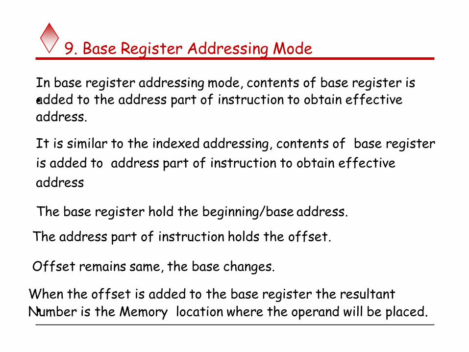
9. Base Register Addressing Mode
•
In base register addressing mode, contents of base register isadded to the address part of instruction to obtain effectiveaddress.
It is similar to the indexed addressing, contents of base register
is added to address part of instruction to obtain effective
address
The base register hold the beginning/base address.
The address part of instruction holds the offset.
Offset remains same, the base changes.
•
When the offset is added to the base register the resultant Number is the Memory location where the operand will be placed.

Ex. Base Register Addressing
Offset= 0001h
Effective address of operand = Base Register + offset
2807
2806
2805
2804
2803
2802
2801
2800
2807
2806
2805
2804
2803
2802
2801
2800
2807
2806
2805
2804
2803
2802
2801
2800
2807
2806
2805
2804
2803
2802
2801
2800
BaseBaseBaseBase
2800h + 0001h = 2801h
2801h + 0001h = 2802h
2802h + 0001h = 2803h
2803h + 0001h = 2804h
2800 280328022801
22
FF
6D
59
08
2E
F3
9F
22
FF
6D
59
08
2E
F3
9F
22
FF
6D
59
08
2E
F3
9F
22
FF
6D
59
08
2E
F3
9F

Ex. Base Register Addressing
Offset= 0003h
Effective address of operand = Base Register + offset
2807
2806
2805
2804
2803
2802
2801
2800
2807
2806
2805
2804
2803
2802
2801
2800
2807
2806
2805
2804
2803
2802
2801
2800
2807
2806
2805
2804
2803
2802
2801
2800
BaseBaseBaseBase
2800h + 0003h = 2803h
2801h + 0003h = 2804h
2802h + 0003h = 2805h
2803h + 0003h = 2806h
2800 280328022801
22
FF
6D
59
08
2E
F3
9F
22
FF
6D
59
08
2E
F3
9F
22
FF
6D
59
08
2E
F3
9F
22
FF
6D
59
08
2E
F3
9F

10.Additional Modes
Autoincrement mode – the effective address of the operand is the contents of a register specified in the instruction. After accessing the operand, the contents of this register are automatically incremented to point to the next item in a list.
(Ri)+. The increment is 1 for byte-sized operands, 2 for 16-bit operands, and 4 for 32-bit operands.
Autodecrement mode: -(Ri) – decrement first
Figure 2.16.The Autoincrement addressing mode used in the program
R0Clear
R0,SUM
R1
(R2)+,R0
Initialization
Move
LOOP Add
Decrement
LOOP
#NUM1,R2
N,R1Move
Move
Branch>0
82Chapter 2 - Machine Instructions & Programs

10(a). Autoincrement Addressing
At start:
HL
2807
2806
2805
2804
2803
2802
2801
2800
2807
2806
2805
2804
2803
2802
2801
2800
2807
2806
2805
2804
2803
2802
2801
2800
2807
2806
2805
2804
2803
2802
2801
2800
HL HL HLHL
1stTime
2ndTime
3rdTime
4thTime
2802 280528042803
22
FF
6D
59
08
2E
F3
9F
22
FF
6D
59
08
2E
F3
9F
22
FF
6D
59
08
2E
F3
9F
22
FF
6D
59
08
2E
F3
9F
2802
HL pair incremented after its value is used

HL pair decremented before its value is used
At start:
HL
2807
2806
2805
2804
2803
2802
2801
2800
2807
2806
2805
2804
2803
2802
2801
2800
2807
2806
2805
2804
2803
2802
2801
2800
2807
2806
2805
2804
2803
2802
2801
2800
HL HL HLHL
1stTime
2ndTime
3rdTime
4thTime
2804 280728062805
22
FF
6D
59
08
2E
F3
9F
22
FF
6D
59
08
2E
F3
9F
22
FF
6D
59
08
2E
F3
9F
22
FF
6D
59
08
2E
F3
9F
2807
10(b). Autodecrement Addressing

Addressing modes
Mode Assembly Register Transfer
Direct address LD ADR AC ← M[ADR]
Indirect address LD @ADR AC ← M[M[ADR]]
Immediate operand LD # NBR AC ← NBR
Relative address LD $ADR AC ← M[PC +ADR]
Index addressing LD ADR(XR) AC ← M[ADR +XR]
Base register addr LD ADR (BR) AC←M [ADR +BR]
Register LD R1 AC ← R1
Register indirectLD (R1) / MOV A, @R1
AC ← M[R1]
Autoincrement LD (R1)+ AC ← M[R1], R1 ← R1+1
Autodecrement LD –(R1) AC← M [R1], R1← R1-1
85Chapter 2 - Machine Instructions & Programs

Addressing Modes-additional
The different ways in which the location of an operand is specified in an instruction are referred to as addressing modes.
Name Assembler syntax Addressingfunction
Immediate #Value Operand = Value
Register R i EA = Ri
Absolute(Direct) LOC EA = LOC
Indirect (Ri ) EA = [Ri ]
(LOC) EA = [LOC]
Index X(R i) EA = [Ri ] + X
Basewith index (Ri ,Rj ) EA = [Ri ] + [Rj ]
Basewith index X(R i ,Rj ) EA = [Ri ] + [Rj ] + X
and offset
Relative X(PC) EA = [PC] + X
Autoincrement (Ri )+ EA = [Ri ] ;Increment R i
Autodecrement (R i ) Decrement R i ;
EA = [Ri ]
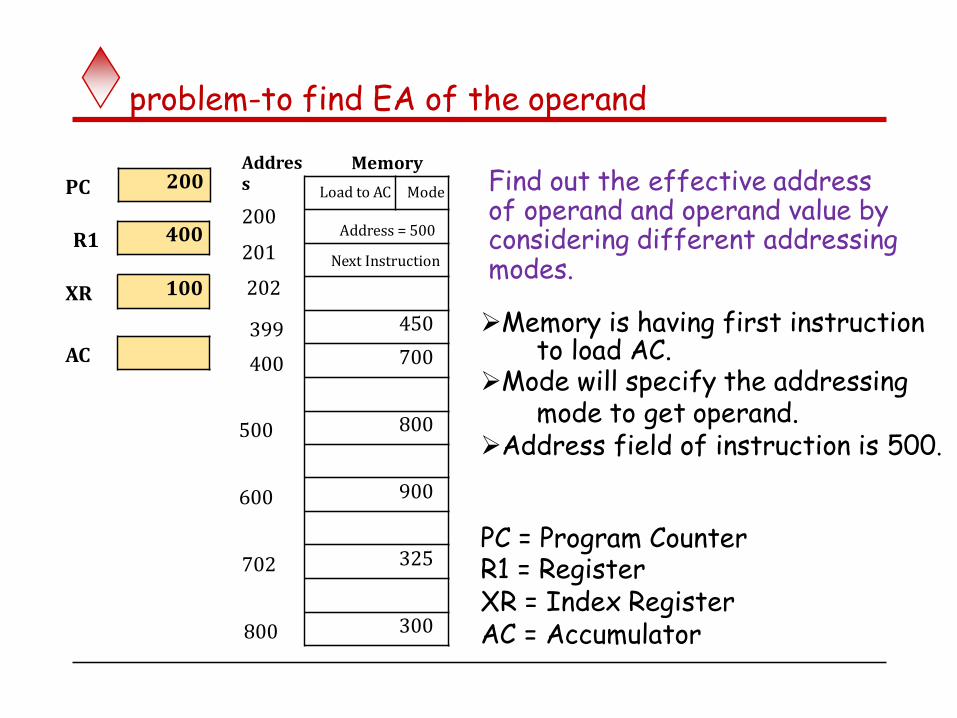
problem-to find EA of the operand
Memory is having first instruction to load AC.
Mode will specify the addressing mode to get operand.
Address field of instruction is 500.
Find out the effective address of operand and operand value by considering different addressing modes.
Address
200
201
202
Memory
PC
R1
XR
399
400AC
500
600
702
800
100
400
Load to AC Mode
Address = 500
Next Instruction
450
700
800
900
325
300
200
PC = Program CounterR1 = RegisterXR = Index RegisterAC = Accumulator

Problem-solution- immediate addressing mode
1. Immediate Addressing Mode
As instruction contains immediate number 500.
It is stored as address 201.
Operand = 500
AC 500
Address Memory
PC
R1
XR
AC
100
400
200Load to AC Mode
201 Address = 500
202
399
400
500
600
702
800
Next Instruction
450
700
800
900
325
300
200
LDI 500
Effective Address = 201

Problem-solution- reg. mode
2. Register Addressing Mode
••
Register R1 contains 400.As operand is in register so no any memory location.
Effective Address = NilOperand = 400
AC 400
Address
200
201
202
Memory
PC
R1
XR
399
400AC
500
600
702
800
100
400
Load to AC Mode
Address = 500
Next Instruction
450
700
800
900
325
300
200

solution -reg indirect mode
Address Memory
PC 3. Register Indirect Addressing Mode
R1Register R1 contains 400.So effective address of operand is 400. The data stored at 400 is 700.
XR
AC
Effective Address = 400Operand = 700
AC 700
100
400
200
201
202
399
Load to AC Mode
Address = 500
Next Instruction
450
400 700
500
600
702
800
800
900
325
300
200

solution-direct addressing
PC4. Direct Addressing Mode
R1Instruction contains the address 500.So effective address of operand is 500. The data stored at 500 is 800.Effective Address = 500Operand = 800
AC 800
Address Memory
XR
AC
100
400
200
201
202
399
400
Load to AC Mode
Address = 500
Next Instruction
450
700
500 800
600
702
800
900
325
300
200

solution -indirect addressing
5. Indirect Addressing Mode
R1Instruction contains the address 500.Address at 500 is 800.So effective address of operand is 800. The data stored at 800 is 300.
XR
AC
Effective Address = 800Operand = 300
AC 300
Address Memory
PC
100
400
200
201
202
399
400
500
600
702
Load to AC Mode
Address = 500
Next Instruction
450
700
800
900
325
800 300
200

solution-relative addressing
6. Relative Addressing Mode
PC = 200.Offset = 500.Instruction is of 2 bytes.So effective address = PC + 2 + offset = 200 + 500 +2 = 702 .The data stored at 702 is 325.
Effective Address = 702Operand = 325
AC 325
Address Memory
PC
R1
XR
AC
100
400
200
201
202
399
400
500
600
Load to AC Mode
Address = 500
Next Instruction
450
700
800
900
702 325
800 300
200

Problem-solution-index addressing
7. Index Addressing Mode
XR = 100.Base = 500.So effective address = Base + XR =
500 + 100 = 600 . The data stored at 600 is 900.
Effective Address = 600Operand = 900
AC 900
Address Memory
PC
R1
XR
AC
100
400
200
201
202
399
400
500
Load to AC Mode
Address = 500
Next Instruction
450
700
800
600 900
702
800
325
300
200

solution -autoincrement addressing
8. Autoincrement Addressing Mode
It is same as register indirect addressing mode exceptthe contents of R1 are incremented after the execution. R1 contains 400.So effective address of operand is 400. The data stored at 400 is 700.
Effective Address = 400Operand = 700
R1
AC 700
401
Address Memory
PC
R1
XR
AC
100
400
200
201
202
396
Load to AC Mode
Address = 500
Next Instruction
450
400 700
500
600
702
800
800
900
325
300
200
404

solution-autodecrement addressing
9. Autodecrement Addressing Mode
It is same as register indirect addressing mode except the contents of R1 are decremented before the execution.R1 contains 400.R1 is first decremented to 399.So effective address of operand is 399.The data stored at 399 is 450.
Effective Address = 399Operand = 450
R1
AC450
399
Next Instruction
Address Memory
PC
R1
XR
AC
100
400
200
201
202
Load to AC Mode
Address = 500
399 450
400
500
600
702
800
700
800
900
325
300
200

Complete solution
Addressing Mode EA Operand
Immediate Addressing Mode 201 500
Register Addressing Mode Nil 400
Register Indirect Addressing Mode 400 700
Direct Addressing Mode 500 800
Indirect Addressing Mode 800 300
Relative Addressing Mode 702 325
Indexed Addressing Mode 600 900
Autoincrement Addressing Mode 400 700
Autodecrement Addressing Mode 399 450

Chapter 2 - Machine Instructions & Programs 98
Problem5: Consider a 16-bit processor in which the following appears in main memory, starting at location 200:
200 Load to AC Mode
201 500
202 Next instruction
The first part of the first word indicates that this instruction loads a value into an accumulator. The Mode field specifies an addressing mode and, if appropriate, indicates a source register; assuming that when used, the source register is R1, which has a value of 400There is also a base register that contains the value of 100. the value of 500 in location 201 may be part of the address calculation. Assume that location 399 contains the value 999, location 400 contains the value 1000, and so on. Determine the effective address and the operand to be loaded for the following addressing modes:
Problem 5- home assignment

Solution (problem 5)-addressing modes
Effective Address?Operand In AC ?
200
Address Memory
PC
R1
BR
XR
AC
100
400
200
201
202
Load to AC Mode
Address = 500
Next Instruction
399 999
400
500
600
702
11000
1000
1100
1200
1302
1700
200

Chapter 2 - Machine Instructions & Programs 100
EA Operand
a 500 1100
b 201 500
c 1100 1700
d 201+1+500 =702 1302
e 500+100=600 1200
f R1 400
g 400 1000
h 400 1000
Final Solution (problem 5)
Mode ?
Note. Identify the addressing mode and fill the lost column

Problem 6 -Home assignment
Memory is having first instruction to load AC.
Mode will specify the addressing mode to get operand.
Address field of instruction is 1000.
Find out the effective address of operand and operand value by considering different addressing modes.
PC = Program CounterR1 = RegisterXR = Index RegisterAC = Accumulator
The word length of the processor is 4 bytes.
Address
200
202
204
Memory
PC
R1
XR
396
400AC
1000
1400
1700
2000
400
1000
Load to AC Mode
Address = 1000
Next Instruction
450
700
1800
900
325
300
1000
1004
996
1800 625
1204
800

Chapter 2 - Machine Instructions & Programs 102
Problem 7:Register R1 and R2 contain values 1800 and 3800 respectively. The word length of the processor is 4 bytes. What is the effective address of the memory operand in each one of the following cases?
1) ADD 100 (R2), R6.2) LOAD R6, 20 (R1,R2) 3) STORE –(R2), R6 4) SUBTRACT (R2)+, R6

Chapter 2 - Machine Instructions & Programs 103
Solution (problem 7)1) Effective address = 100 + Contents of R2 = 100 + 3800 = 3900.2) Effective address = 20 + Contents of R1 + Contents of R2
= 20 + 1800 + 3800 = 5620.3) Effective address = Contents of R2 – 4 = 3800 – 4 = 3796.4) Effective address = Contents of R2 = 3800.

Chapter 2 - Machine Instructions & Programs 104
Problem: 8Given the following memory values and a one-address machine with an accumulator: Word 20 contains 40 Word 30 contains 50 Word 40 contains 60 Word 50 contains 70 What values do the following instructions load into the Accumulator? a) Load IMMEDIATE 20 b) Load DIRECT 20 c) Load INDIRECT 20 d) Load IMMEDIATE 30 e) Load DIRECT 30 f) Load INDIRECT 30

Chapter 2 - Machine Instructions & Programs 105
Solution(problem 8)a) 20 b) 40 c) 60 d)30 e) 50 f) 70

Chapter 2 - Machine Instructions & Programs 106
Let the address stored in the program counter be designated by the symbol X1. The instruction stored in X1 has an address part
(operand reference) X2. The operand needed to execute the instruction is stored in the memory word with address X3. An index register contains the value X4. What is the relationship between these various quantities if the addressing mode of the instruction is a) Direct. b) indirect. c) PC relative. d) indexed
Problem: 9

Chapter 2 - Machine Instructions & Programs 107
Solution: (problem 9)a) X3=X2 b) X3=(X2) c) X3=X1+X2+1 d) X3=X2+X4
Chapter 2 - Machine Instructions & Programs 108
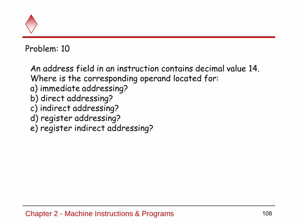
An address field in an instruction contains decimal value 14. Where is the corresponding operand located for: a) immediate addressing? b) direct addressing? c) indirect addressing? d) register addressing? e) register indirect addressing?
Problem: 10

Chapter 2 - Machine Instructions & Programs 109
Solution (problem 10)a) 14 (The address field). b) Memory location 14. c) The memory location whose address is in memory location 14. d) Register 14. e) The memory location whose address is in register 14

Assembly Language
110Chapter 2 - Machine Instructions & Programs

Chapter 2 - Machine Instructions & Programs 111
Machine instructions are represented by patterns of 0s and 1s. Such patterns are awkward to deal with when discussing or preparing programs. Therefore, we use symbolic names to represent the patterns. EX. Move, Add, Increment, and Branch, for the instruction operations to represent the corresponding binary code patterns.When writing programs for a specific computer, such words arenormally replaced by acronyms called mnemonics, such as MOV, ADD, INC, and BR.Programs written in an assembly language can be automatically translated into a sequence of machine instructions by a program called an assembler.
The assembler program is one of a collection of utility programs that are a part of the system software.The assembler, like any other program, is stored as a sequence of machine instructions in the memory of the computer.
A user program is usually entered into the computer through a keyboard and stored either in the memory or on a magnetic disk. The user program is simply a set of lines of alphanumeric characters.

Chapter 2 - Machine Instructions & Programs 112
When the assembler program is executed, it reads the user program,
analyzes it, and then generates the desired machine language program.
The latter contains patterns of 0s and 1s specifying instructions that will
be executed by the computer.
The user program in its original alphanumeric text format is called a
source program, and the assembled machine language program is called
an object program.

Human-Readable Machine Language
Computers understand ones and zeros…
Humans like symbols…
Assembler is a program that turns symbols intomachine instructions.
ISA-specific:close correspondence between symbols and instruction set
• mnemonics for opcodes
• labels for memory locations
additional operations for allocating storage and initializing data
ADD R6,R2,R6 ; increment index reg.
0001110010000110

Assembly Language Syntax
Each line of a program is one of the following:
an instruction
an assember directive (or pseudo-op) (SUM EQU 200)
a comment
Whitespace (between symbols) and case are ignored.
Comments (beginning with “;”) are also ignored.
An instruction has the following format:
LABEL OPCODE OPERANDS ; COMMENTS
optional mandatory

Opcodes and Operands
Opcodes reserved symbols that correspond to instructions
• ex: ADD, AND, LD, LDR, … Operands
registers -- specified by Rn, where n is the register number numbers -- indicated by # (decimal) or x (hex) label -- symbolic name of memory location separated by comma number, order, and type correspond to instruction format
• ex:ADD R1,R1,R3
ADD R1,R1,#3
LD R6,NUMBER
BRz LOOP

Labels and Comments
Label
placed at the beginning of the line
assigns a symbolic name to the address corresponding to line
• ex:LOOP ADD R1,R1,#-1
BRp LOOP
Comment
anything after a semicolon is a comment
ignored by assembler
used by humans to document/understand programs
tips for useful comments:
• avoid restating the obvious, as “decrement R1”
• provide additional insight, as in “accumulate product in R6”
• use comments to separate pieces of program

Assembler Directives
Pseudo-operations
do not refer to operations executed by program
used by assembler
look like instruction, but “opcode” starts with dot
Opcode Operand Meaning
.ORIG address starting address of program
.END end of program
.BLKW n allocate n words of storage
.FILL n allocate one word, initialize with
value n
.STRINGZ n-character
string
allocate n+1 locations,
initialize w/characters and null
terminator

Style Guidelines
Use the following style guidelines to improvethe readability and understandability of your programs:
1. Provide a program header, with author’s name, date, etc.,and purpose of program.
2. Start labels, opcode, operands, and comments in same columnfor each line. (Unless entire line is a comment.)
3. Use comments to explain what each register does.
4. Give explanatory comment for most instructions.
5. Use meaningful symbolic names.
• Mixed upper and lower case for readability.
• ASCIItoBinary, InputRoutine, SaveR1
6. Provide comments between program sections.
7. Each line must fit on the page -- no wraparound or truncations.
• Long statements split in aesthetically pleasing manner.
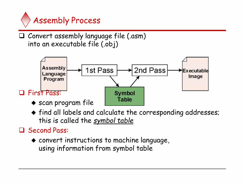
Assembly Process
Convert assembly language file (.asm)into an executable file (.obj)
First Pass:
scan program file
find all labels and calculate the corresponding addresses;this is called the symbol table
Second Pass:
convert instructions to machine language,using information from symbol table
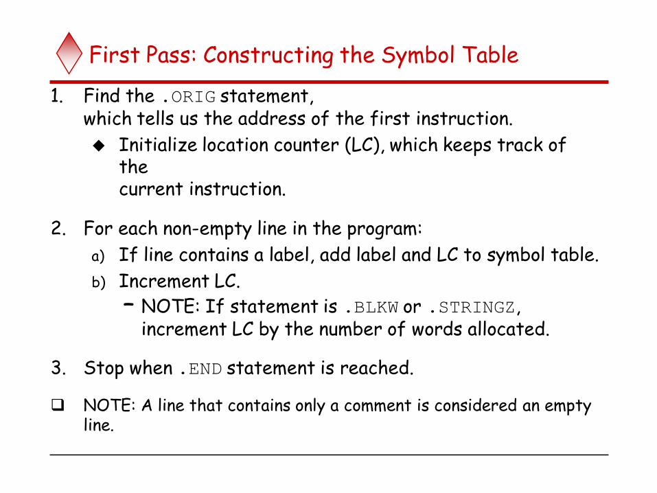
First Pass: Constructing the Symbol Table
1. Find the .ORIG statement,which tells us the address of the first instruction.
Initialize location counter (LC), which keeps track of thecurrent instruction.
2. For each non-empty line in the program:
a) If line contains a label, add label and LC to symbol table.
b) Increment LC.
– NOTE: If statement is .BLKW or .STRINGZ,increment LC by the number of words allocated.
3. Stop when .END statement is reached.
NOTE: A line that contains only a comment is considered an empty line.

Practice
Construct the symbol table
Symbol Address
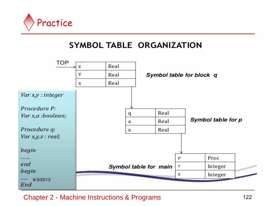
Practice
Construct the symbol table
Symbol Address
122Chapter 2 - Machine Instructions & Programs

Second Pass: Generating Machine Language
For each executable assembly language statement,generate the corresponding machine language instruction. If operand is a label,
look up the address from the symbol table.

Linking and Loading
Loading is the process of copying an executable imageinto memory.
more sophisticated loaders are able to relocate imagesto fit into available memory
must readjust branch targets, load/store addresses
Linking is the process of resolving symbols betweenindependent object files.
suppose we define a symbol in one module,and want to use it in another
some notation, such as .EXTERNAL, is used to tell assembler that a symbol is defined in another module
linker will search symbol tables of other modules to resolve symbols and complete code generation before loading

Types of Instructions
Data Transfer Instructions
Name Mnemonic
Load LD
Store ST
Move MOV
Exchange XCH
Input IN
Output OUT
Push PUSH
Pop POP
Data value is not modified
125Chapter 2 - Machine Instructions & Programs

Data Transfer Instructions
Mode Assembly Register Transfer
Direct address LD ADR AC ← M[ADR]
Indirect address LD @ADR AC ← M[M[ADR]]
Relative address LD $ADR AC ← M[PC+ADR]
Immediate operand LD # NBR AC ← NBR
Index addressing LD ADR(X) AC ← M[ADR+XR]
Register LD R1 AC ← R1
Register indirect LD (R1) AC ← M[R1]
Autoincrement LD (R1)+ AC ← M[R1], R1 ← R1+1
126Chapter 2 - Machine Instructions & Programs

Data Manipulation Instructions
Arithmetic
Logical & Bit Manipulation
Shift
Name Mnemonic
Clear CLRComplement COM
AND ANDOR OR
Exclusive-OR XORClear carry CLRCSet carry SETC
Complement carry COMCEnable interrupt EIDisable interrupt DI
Chapter 2 - Machine Instructions & Programs
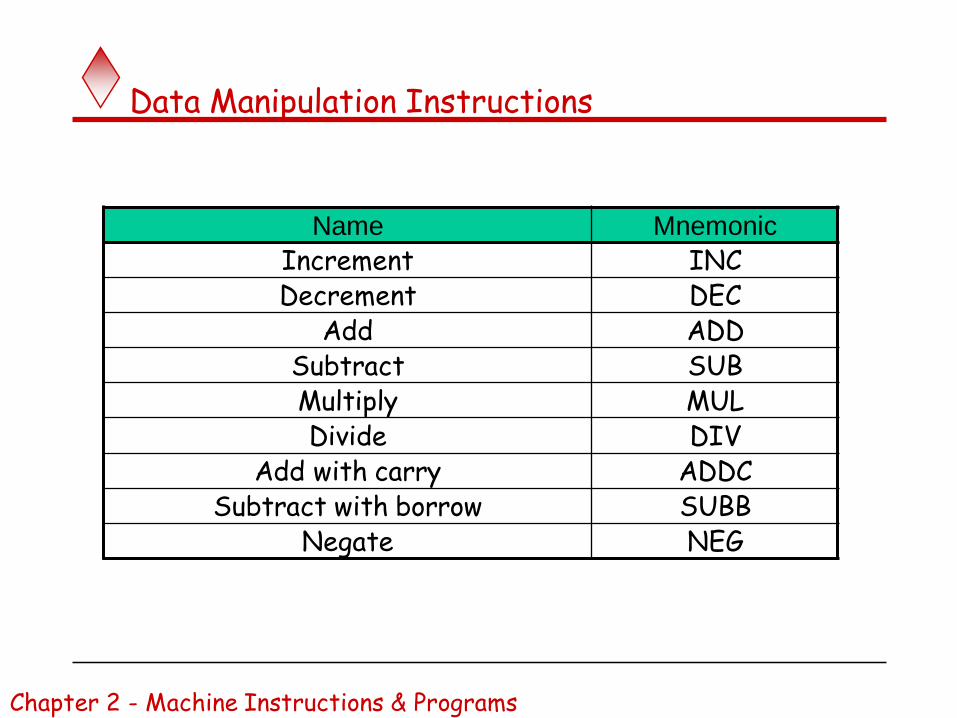
Name Mnemonic
Increment INCDecrement DEC
Add ADDSubtract SUBMultiply MULDivide DIV
Add with carry ADDCSubtract with borrow SUBB
Negate NEG
Chapter 2 - Machine Instructions & Programs
Data Manipulation Instructions

Data Manipulation Instructions
Name Mnemonic
Logical shift right SHRLogical shift left SHL
Arithmetic shift right SHRAArithmetic shift left SHLA
Rotate right RORRotate left ROL
Rotate right through carry RORC
Rotate left through carry ROLC
Chapter 2 - Machine Instructions & Programs

Program Control Instructions
Name Mnemonic
Branch BR
Jump JMP
Skip SKP
Call CALL
Return RET
Compare (Subtract)
CMP
Test (AND) TST
Subtract A – B but don’t store the result
1 0 1 1 0 0 0 1
0 0 0 0 1 0 0 0
0 0 0 0 0 0 0 0
Mask
130Chapter 2 - Machine Instructions & Programs

Conditional Branch Instructions
Mnemonic Branch ConditionTested
Condition
BZ Branch if zero Z = 1
BNZ Branch if not zero Z = 0
BC Branch if carry C = 1
BNC Branch if no carry C = 0
BP Branch if plus S = 0
BM Branch if minus S = 1
BV Branch if overflow V = 1
BNVBranch if no
overflowV = 0
131Chapter 2 - Machine Instructions & Programs

Basic Input/output Operations
132Chapter 2 - Machine Instructions & Programs

I/O
The data on which the instructions operate are not necessarily already stored in memory.
Data need to be transferred between processor and outside world (disk, keyboard, etc.)
I/O operations are essential, the way they are performed can have a significant effect on the performance of the computer.
133Chapter 2 - Machine Instructions & Programs
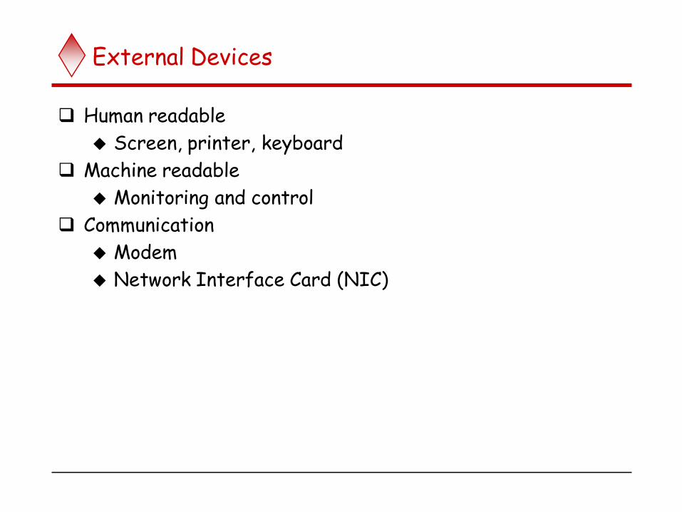
External Devices
Human readable
Screen, printer, keyboard
Machine readable
Monitoring and control
Communication
Modem
Network Interface Card (NIC)

Generic Model of I/O Module

External Device Block Diagram

Typical I/O Data Rates

I/O Module Function
Control & Timing
CPU Communication
Device Communication
Data Buffering
Error Detection

I/O Steps
CPU checks I/O module device status
I/O module returns status
If ready, CPU requests data transfer
I/O module gets data from device
I/O module transfers data to CPU
Variations for output, DMA, etc.

Input Output Techniques
Programmed
Interrupt driven
Direct Memory Access (DMA)

Programmed I/O
CPU has direct control over I/O
Sensing status
Read/write commands
Transferring data
CPU waits for I/O module to complete operation
Wastes CPU time

Programmed I/O - detail
CPU requests I/O operation
I/O module performs operation
I/O module sets status bits
CPU checks status bits periodically
I/O module does not inform CPU directly
I/O module does not interrupt CPU
CPU may wait or come back later

Program-Controlled I/O Example
Read in character input from a keyboard and produce character output on a display screen.
Rate of data transfer (keyboard, display, processor) Difference in speed between processor and I/O device
creates the need for mechanisms to synchronize the transfer of data.
A solution: on output, the processor sends the first character and then waits for a signal from the display that the character has been received. It then sends the second character. Input is sent from the keyboard in a similar way.
On Input , the processor waits for a signal indicating that a character key has been struck and that its code is available in some buffer register associated with the keyboard. Then the processor proceeds to read that code.
143Chapter 2 - Machine Instructions & Programs

Addressing I/O Devices
Under programmed I/O data transfer is very like memory access (CPU viewpoint)
Each device given unique identifier
CPU commands contain identifier (address)

Program-Controlled I/O Example
DATAIN DATAOUT
SIN SOUT
Key board Display
Bus
Figure 2.19 Bus connection for processor, keyboard, and display.
Processor
- Registers- Flags (status register)- Device interface
145Chapter 2 - Machine Instructions & Programs
Status register Status register

146
difference in speed between the processor and I/O devices creates the need for mechanisms to synchronize the transfer of data between them.A solution to this problem is as follows; On output, the processor sends the first character and then waits for a signal from the display that the character has been received. It then sends the second character, and so on. Input is sent from the keyboard in a similar way; the processor waits for a signal indicating that a character key has been struck and that its code is available in some buffer register associated with the keyboard. Then the processor proceeds to read that code.

147
The keyboard and the display are separate devices as shown in Figure .The action of striking a key on the key board does not automatically cause the corresponding character to be displayed on the screen.One block of instructions in the I/O program transfers the
character into the processor, and another associated block of instructions causes the character to be displayed.

148
Moving a character code from the keyboard to the processor. Striking a key stores the corresponding character code in an 8-bit buffer register associated with the keyboard. Let us call this register DATAIN, as shown in Figure.To inform the processor that a valid character is in DATAIN, a status control flag, SIN, is set to 1. A program monitors SIN, and when SIN is set to 1, the processor reads the contents of DATAIN. When the character is transferred to the processor, SIN is automatically cleared to 0. If a second character is entered at the keyboard, SIN is again set to 1 and the process repeats.

149
Characters transfer from the processor to the displayA buffer register, DATAOUT, and a status control flag, SOUT, are used for this transfer. When SOUT equals 1,the display is ready to receive a character. Under program control, the processor monitors SOUT, and when SOUT is set to 1, the processor transfers a character code to DATAOUT. The transfer of a character to DATAOUT clears SOUT to 0.If the display device is ready to receive a second character, SOUT is again set to 1. The buffer registers DATAIN and DATAOUT and the status flags SIN and SOUT are part of circuitry commonly known as a device interface. The circuitry for each device is connected to the processor via a bus.

150
In order to perform I/O transfers, we need machine instructions that can check the state of the status flags and transfer data between the processor and the I/O device. These instructions are similar in format to those used for moving data between the processor and the memory. For example, the processor can monitor the keyboard status flag SIN and transfer a character from DATAIN to register R1 by the following sequence of operations:
READWAIT Branch to READWAIT if SIN = 0Input from DATAIN to R1
I/O transfer
Sequence of operations is used for transferring input to processor

151
The Branch operation is usually implemented by two machine instructions. The first instruction tests the status flag and the second performs the branch. Although the details vary from computer to computer, the main idea is that the processor monitors the status flag by executing a short wait loop and proceeds to transfer the input data when SIN is set to 1 as a result of a key being struck. The Input operation resets SIN to 0.An analogous sequence of operations is used for transferring output to the display.An example is
WRTTEWAIT Branch to WRITEWATT if SOUT = 0Output from R1 to DATAOUT
Sequence of operations for transferring output to the display

152
Again, the Branch operation is normally implemented by two machine instructions. The wait loop is executed repeatedly until the status flag SOUT is set to 1 by the display when it is free to receive a character. The Output operation transfers a character from R1 to DATAOUT to be displayed, and it clears SOUT to 0.
We assume that the initial state of SIN is 0 and the initial state of SOUT is 1. This initialization is normally performed by the device control circuits when the devices are placed under computer control before program execution begins.

153
Until now, we have assumed that the addresses issued by the processor to access instructions and operands always refer to memory locations. Many computers use an arrangement called memory-mapped I/O in which some memory address values areused to refer to peripheral device buffer registers, such as DATAIN and DATAOUT.Thus, no special instructions are needed to access the contents of these registers; data can be transferred between these registers and the processor using instructions that we have already discussed, such as Move, Load, or Store. For example, the contents of the keyboard character buffer DATAIN can be transferred to register R1 in the processorby the instruction
MoveByte DATAIN,R1

154
Similarly, the contents ofregister R1 can be transferred to DATAOUT by the instruction
MoveByte Rl,DATAOUTThe status flags SIN and SOUT are automatically cleared when the buffer registers DATAIN and DATAOUT are referenced, respectively.

155
The MoveByte operation code signifies that the operand size is a byte, to distinguish it from the operation codeMove that has been used for word operands. the two data buffets in Figure may be addressed as if they were two memory locations. It is possible to deal with the status flags SIN and SOUT in the same way, by assigning themdistinct addresses. However, it is more common to include SIN and SOUT in device status registers, one for each of the two devices. Let us assume that bit in registers INSTATUS and OUTSTATUS corresponds to SIN and SOUT, respectively. The read Operation just described may now be implemented by the machine instruction sequence

156
READWAIT Testbit #3,INSTATUSBranch=0 READWAITMoveByte DATAIN,R1
The write operation may be implemented as
WRITEWAIT Testbit #3.0UTSTATUSBranch=0 WRITEWAITMoveByte R1,DATA0UT

157
The Test bit instruction tests the state of one bit in the destination location, where the bit position to be tested is indicated by the first operand. If the bit tested is equal to 0, then the condition of the branch instruction is true, and a branch is made to the beginningof the wait loop. When the device is ready, that is, when the bit tested becomes equal to 1, the data are read from the input buffer or written into the output buffer.
The program shown ,uses these two operations to read a line of characters typed at a keyboard and send them out to a display device. As the characters are read in, one by one, they are stored in a data area in the memory and then echoed back to display,

158
159
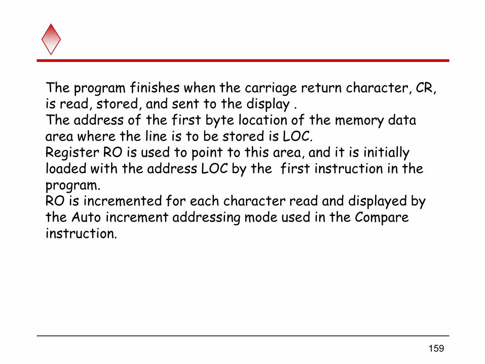
The program finishes when the carriage return character, CR, is read, stored, and sent to the display . The address of the first byte location of the memory data area where the line is to be stored is LOC. Register RO is used to point to this area, and it is initially loaded with the address LOC by the first instruction in the program. RO is incremented for each character read and displayed by the Auto increment addressing mode used in the Compare instruction.

160
Program -controlled I/O requires continuous involvement of the processor in the I/O activities. Almost all of the execution time for the program is accounted for in the two wait loops, while the processor waits for a character to be struck or for the display to become available. It is desirable to avoid wasting processor execution time in this situation. Other I/O techniques, based on the use of interrupts, may be used to improve the utilization of the processor.

Program-Controlled I/O Example
Machine instructions that can check the state of the status flags and transfer data:READWAIT Branch to READWAIT if SIN = 0
Input from DATAIN to R1
WRITEWAIT Branch to WRITEWAIT if SOUT = 0Output from R1 to DATAOUT
161Chapter 2 - Machine Instructions & Programs

Program-Controlled I/O Example
Memory-Mapped I/O – some memory address values are used to refer to peripheral device buffer registers. No special instructions are needed. Also use device status registers.
READWAIT Testbit #3, INSTATUSBranch=0 READWAITMoveByte DATAIN, R1
162Chapter 2 - Machine Instructions & Programs

Program-Controlled I/O Example
Assumption – the initial state of SIN is 0 and the initial state of SOUT is 1.
Any drawback of this mechanism in terms of efficiency?
Two wait loopsprocessor execution time is wasted
Alternate solution?
Interrupt
163Chapter 2 - Machine Instructions & Programs

I/O Mapping
Memory mapped I/O Devices and memory share an address space
I/O looks just like memory read/write
No special commands for I/O• Large selection of memory access commands available
Isolated I/O Separate address spaces
Need I/O or memory select lines
Special commands for I/O
• Limited set

I/O Commands
CPU issues address
Identifies module (& device if >1 per module)
CPU issues command
Control - telling module what to do
• e.g. spin up disk
Test - check status
• e.g. power? Error?
Read/Write
• Module transfers data via buffer from/to device

Program-Controlled I/O Example
Assumption – the initial state of SIN is 0 and the initial state of SOUT is 1.
Any drawback of this mechanism in terms of efficiency?
Two wait loopsprocessor execution time is wasted
Alternate solution?
Interrupt
166Chapter 2 - Machine Instructions & Programs
Home Work
For each Addressing modes mentioned before, state one example for each addressing mode stating the specific benefit for using such addressing mode for such an application.
167Chapter 2 - Machine Instructions & Programs

Stacks
168Chapter 2 - Machine Instructions & Programs

What is a stack?
A stack is a list with the restriction that insertions and deletions can only be
performed at the top of the list
The other end is called bottom
The structure is sometimes referred to as a pushdown stack
Stores a set of elements in a particular order Stack principle: LAST IN FIRST OUT ( LIFO)
Example
In order to organize the control and information linkage between the main program and the subroutine, a data structure called a stack is used.It is also used to describe this type of storage mechanism;the last data item placed on the stack is the first one removed when retrieval begins.
The terms push and pop are used to describe placing a new item on the
stack and removing the top item from the stack, respectively.

Push and Pop
Primary operations: Push and Pop
Push - Add an element to the top of the stack
Pop - Remove the element at the top of the stack
Atop
empty stack
top
top
top
push an element push another
A
B
pop
A
When a stack is used in a program, it is usually allocated a fixed amount of space in the memory. In this case, we must avoid pushing an item onto the stack when thestack has reached its maximum size. Also, we must avoid attempting to pop an item off an empty stack, which could result from a programming error.

Last In First Out
B
A
D
C
B
A
C
B
A
D
C
B
A
E
D
C
B
Atop
top
top
top
top
A

Stack Applications
Real life
Pile of books
Plate trays
Imagine a pile of trays in a cafeteria; customers pick up new trays from the top of the pile, and clean trays are added to the pile by placing them onto the top of the pile
More applications related to computer science
Program execution stack (read more from your text)
Evaluating expressions
conversion of infix to postfix
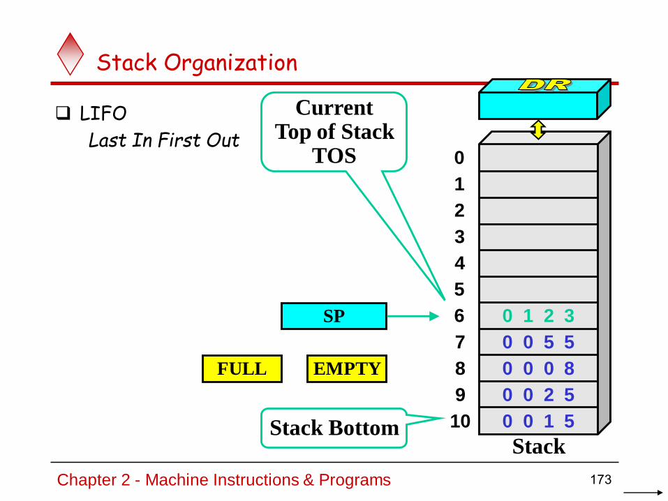
Stack Organization
LIFO
Last In First Out
SP
Stack Bottom
CurrentTop of Stack
TOS 0
1
2
3
4
7
8
9
10
5
6
Stack
0 0 5 5
0 0 0 8
0 0 2 5
0 0 1 5
0 1 2 3
FULL EMPTY
173Chapter 2 - Machine Instructions & Programs

Stack Organization
PUSH
SP ← SP – 1
M[SP] ← DR
If (SP = 0) then (FULL ← 1)
EMPTY ← 0
SP
Stack Bottom
CurrentTop of Stack
TOS 0
1
2
3
4
7
8
9
10
5
6
Stack
0 0 5 5
0 0 0 8
0 0 2 5
0 0 1 5
0 1 2 3
FULL EMPTY
1 6 9 0
1 6 9 0CurrentTop of Stack
TOS
174Chapter 2 - Machine Instructions & Programs

Stack Organization
POP
DR ← M[SP]
SP ← SP + 1
If (SP = 11) then (EMPTY ← 1)
FULL ← 0
SP
Stack Bottom
CurrentTop of Stack
TOS 0
1
2
3
4
7
8
9
10
5
6
Stack
0 0 5 5
0 0 0 8
0 0 2 5
0 0 1 5
0 1 2 3
FULL EMPTY
1 6 9 01 6 9 0
CurrentTop of Stack
TOS
175Chapter 2 - Machine Instructions & Programs

0
1
2
102
202
201
200
100
101
Stack Organization
Memory Stack
PUSH
SP ← SP – 1
M[SP] ← DR
POP
DR ← M[SP]
SP ← SP + 1
PC
AR
SP
176Chapter 2 - Machine Instructions & Programs

Reverse Polish Notation
Infix Notation
A + B
Prefix or Polish Notation
+ A B
Postfix or Reverse Polish Notation (RPN)
A B +
A B + C D A B C D +RPN
(2) (4) (3) (3) +
(8) (3) (3) +
(8) (9) +
17
177Chapter 2 - Machine Instructions & Programs
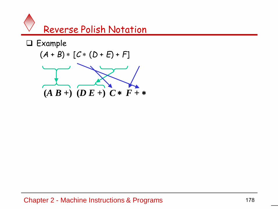
Reverse Polish Notation
Example
(A + B) [C (D + E) + F]
(A B +) (D E +) C F +
178Chapter 2 - Machine Instructions & Programs

Reverse Polish Notation
Stack Operation
(3) (4) (5) (6) +
PUSH 3
PUSH 4
MULT
PUSH 5
PUSH 6
MULT
ADD3
4
12
5
6
30
42
179Chapter 2 - Machine Instructions & Programs

The Towers of HanoiA Stack-based Application
GIVEN: three poles
a set of discs on the first pole, discs of different sizes, the smallest discs at the top
GOAL: move all the discs from the left pole to the right one.
CONDITIONS: only one disc may be moved at a time.
A disc can be placed either on an empty pole or on top of a larger disc.

Towers of Hanoi

Towers of Hanoi

Towers of Hanoi

Towers of Hanoi

Towers of Hanoi

Towers of Hanoi

Towers of Hanoi

Towers of Hanoi
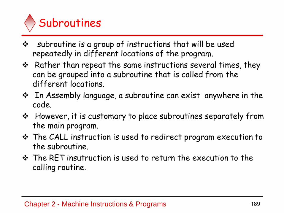
Subroutines
subroutine is a group of instructions that will be used repeatedly in different locations of the program.
Rather than repeat the same instructions several times, they can be grouped into a subroutine that is called from the different locations.
In Assembly language, a subroutine can exist anywhere in the code.
However, it is customary to place subroutines separately from the main program.
The CALL instruction is used to redirect program execution to the subroutine.
The RET insutruction is used to return the execution to the calling routine.
Chapter 2 - Machine Instructions & Programs 189

Subroutines
We should be able to call a subroutine from anywhere in our program. By “call” we mean being able to change control flow so that the routine is executed.
We should be able to pass parameters that may take different values across different calls.
A subroutine must be able to return a value.
A subroutine must be able to change control flow so that execution continues immediately after the point where it was called.
Since a subroutine can be called from many different places this suggests that the routine should be able to differentiate between them and “return” to the right spot depending on where it was called from.
Chapter 2 - Machine Instructions & Programs 190
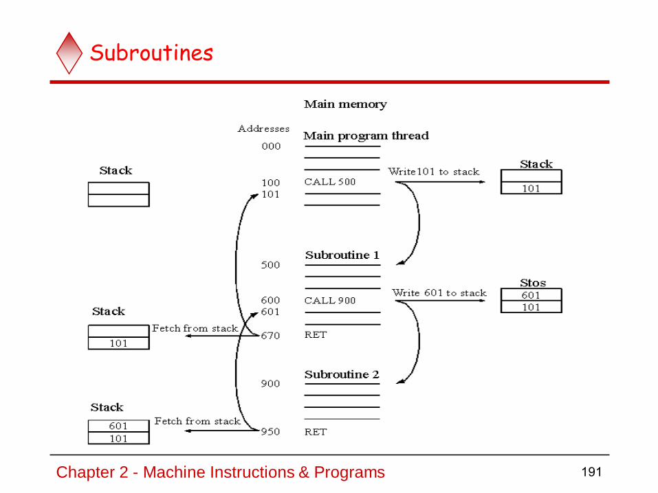
Subroutines
Chapter 2 - Machine Instructions & Programs 191

Subroutines
A subroutine is a section of code which performs a specific task, usually a task which needs to be executed by different parts of the program.
Example:Math functions, such as square root (sqrt)
Because a subroutine can be called from different places in a program, you cannot get out of a subroutine with an instruction such as jmp label
Because you would need to jump to different places depending upon which section of the code called the subroutine.
When you want to call the subroutine your code has to save the address where the subroutine should return to. It does this by saving the return address on the stack.
This is done automatically by using JSR (Jump to Subroutine) or BSR (Branch to Subroutine) .
This instruction pushes the address of the instruction following the JSR (BSR) instruction on the stack
After the subroutine is done executing its code, it needs to return to the address saved on the stack.
This is done automatically when you return from the subroutine by
using RTS (Return from Subroutine) instruction.
This instruction pulls the return address off the stack and loads it into the PC.
Chapter 2 - Machine Instructions & Programs 192

Program using Subroutines
Modify Flag Content using PUSH/POP
Problem: To Reset the Zero Flag
7 6 5 4 3 2 1 0
8085 Flag : S | Z | X |AC|X |P |X |Cy
Program:
MVI HL ,FF BF H
PUSH PSW
PUSH R
AND
POP
Chapter 2 - Machine Instructions & Programs 193
PSW (Program Status Word.This register pair is made up of the Accumulatorand the Flags registersPUSH PSWDecrement SPCopy the contents of register A to the memory location pointed to by SPDecrement SPCopy the contents of Flag register to the memorylocation pointed to by SP
POP PSW (1 Byte Instruction)Copy the contents of the memory location pointed to by the SP to Flag registerIncrement SP.Copy the contents of the memory location pointed to by the SP to register A–Increment SP

Delay subroutine
Write a Program that will display FF and 11 repeatedly on the seven segment display. Write a ‘delay’ subroutine and
Call it as necessary.
00: LXISP FFFF
03: MVIA FF
05: OUT 00
07: CALL 14 20
0A: MVIA 11
0C: OUT 00
0E: CALL 14 20
11: JMP 03 C0
DELAY: 14: MVIB FF
16: MVIC FF
18: DCR C
19: JNZ 18 C0
1C: DCR B
1D: JNZ 16 C0
20: RET
Chapter 2 - Machine Instructions & Programs 194

Queue
Like a stack, a queue is also a list. Stores a set of elements in a particular order Stack principle: FIRST IN FIRST OUT = FIFO It means: the first element inserted is the first one to be
removed Example The first one in line is the first one to be served

Queue Applications
Real life examples
Waiting in line
Waiting on hold for tech support
Applications related to Computer Science
Threads
Job scheduling (e.g. Round-Robin algorithm for CPU allocation)

Queue
Like a stack, a queue is also a list.
With a queue, insertion is done at one end, while deletion is performed at the other end.
Accessing the elements of queues follows a First In, First Out (FIFO) order.
Like customers standing in a check-out line in a store, the first customer in is the first customer served.

A
B
A
C
B
A
D
C
B
A
D
C
Brear
front
rear
front
rear
front
rear
front
rear
front
First In First Out
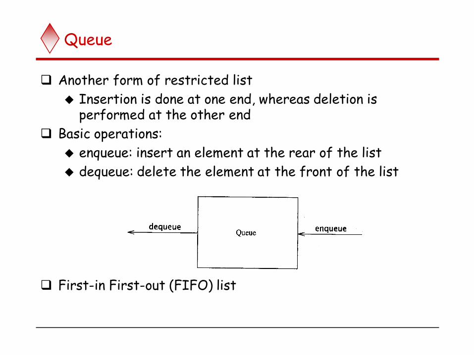
Queue
Another form of restricted list
Insertion is done at one end, whereas deletion is performed at the other end
Basic operations:
enqueue: insert an element at the rear of the list
dequeue: delete the element at the front of the list
First-in First-out (FIFO) list

Enqueue and Dequeue
Primary queue operations: Enqueue and Dequeue
Like check-out lines in a store, a queue has a front and a rear.
Enqueue
Insert an element at the rear of the queue
Dequeue
Remove an element from the front of the queue
Insert
(Enqueue)Remove
(Dequeue) rearfront

Queue Implementation of Array
There are several different algorithms to implement Enqueueand Dequeue
When enqueuing, the front index is always fixed and the rear index moves forward in the array.
front
rear
Enqueue(3)
3
front
rear
Enqueue(6)
3 6
front
rear
Enqueue(9)
3 6 9

Queue Implementation of Array
When enqueuing, the front index is always fixed and the rear index moves forward in the array.
When dequeuing, the element at the front the queue is removed. Move all the elements after it by one position (D1)
When dequeuing, the element at the front the queue is removed. the rear index is always fixed. (D2)
Dequeue()
front
rear
6 9
Dequeue() Dequeue()
front
rear
9
rear = -1
front(D1)
front rear Q[0] Q[1] Q[2] Q[3] Comments
-1
-1
-1
-1
0
1
-1
0
1
2
2
2
J1
J1 J2
J1 J2 J3
J2 J3
J3
queue is empty
Job 1 is added
Job 2 is added
Job 3 is added
Job 1 is deleted
Job 2 is deleted
Applications: Job Scheduling (D2)

EMPTY QUEUE
[2] [3] [2] [3]
[1] [4] [1] [4]
[0] [5] [0] [5]
front = 0 front = 0
rear = 0 rear = 3
J2
J1
J3
Circular queue
Can be seen as a circular queue

FULL QUEUE FULL QUEUE
[2] [3] [2] [3]
[1] [4][1] [4]
[0] [5] [0] [5]
front =0
rear = 5
front =4
rear =3
J2 J3
J1 J4
J5 J6 J5
J7
J8 J9
Leave one empty space when queue is full Why?
How to test when queue is empty?
How to test when queue is full?

Chapter 2 - Machine Instructions & Programs 206
Queues vs stacks
1. One end of the stack is fixed (the bottom), while the other end rises and falls
as data are pushed and popped. A single pointer is needed to point to the top of
the stack at any given time.
On the other hand, both ends of a queue move to higher addresses
as data are added at the back and removed from the front. So two pointers are
needed to keep track of the two ends of the queue.
2.Without further control,a queue would continuously move through the memory
of a computer in the direction of higher addresses.
One way to limit the queue to a fixed region in memory is to use a circular Q.
Let us assume that memory addresses from BEGINNING to
END are assigned to the queue. The first entry in the queue is entered into
location BEGINNING, and successive entries are appended to the queue by
entering them at successively higher addresses.
By the time the back of the queue reaches END, space will have been created at
the beginning if some items have been removed from the queue.
Hence, the back pointer is reset to the value BEGINNING and the process
continues. As in the case of a stack, care must be taken to detect when the
region assigned to the data structure is either completely full or completely
empty.

Logical Shifts
Logical shift – shifting left (LShiftL) and shifting right (LShiftR)
CR00
before:
after:
0
1
0 0 01 1 1 . . . 11
0 0 1 1 1 000
(b) Logical shift right LShiftR #2,R0
(a) Logical shift left LShiftL #2,R0
C R0 0
before:
after:
0
1
0 0 01 1 1 . . . 11
1 10 . . . 00101
. . .
207Chapter 2 - Machine Instructions & Programs

Multiplication and Division-Arithmetic Shifts
CY
before:
after:
0
1
1 1 00 0 1 . . . 01
1 1 0 0 1 011
(c) Arithmetic shift right AShiftR #2,R0
R0
. . .
208Chapter 2 - Machine Instructions & Programs
An arithmetic shift is a microoperation that shifts signed binary number to the left or right. An arithmetic shift left multiplies a signed binary number by 2
and shift right divides by 2. The signed bit remains unchanged whether it is divided or multiplied by 2.
The first (or sign) bit (bit 0) does not participate in the shift.
Arithmetic left Shift:
Arithmetic right Shift
If the number is positive, the leftmost bits will be filled with zero. If the number is negative, the leftmost bits will be filled with ones.

Chapter 2 - Machine Instructions & Programs 209
Arithmetic Shifts
If the bit shifted out of position 1 does not match the sign bit, overflow will occur.
SAME AS LOGICAL LEFT SHIFT!
0
0 1
1

Chapter 2 - Machine Instructions & Programs 210
1) Before: 00001000 ( = 8 decimal )After: 00000100 ( = 4 decimal )
Before: 10000011 ( = -125 decimal in two's complement ) After: 11000001 ( = -63 decimal - one bit is "lost" off the bottom ) After: 11100000 ( = -32 decimal - one bit is "lost" off the bottom ) After: 11110000 ( = -16 decimal ) After: 11111000 ( = -8 decimal ) After: 11111100 ( = -4 decimal ) After: 11111110 ( = -2 decimal )After: 11111111 ( = -1 decimal ) After: 11111111
( = -1 decimal - one bit is "lost" off the bottom )
Arithmetic Right Shift :1 bit

Chapter 2 - Machine Instructions & Programs 211
Look at the 8-bit binary bit patterns below and note the differences between Arithmetic Right Shift and Logical Right Shift:
11110111 (-9) arithmetic-right-shifted gives 11111011 (-5) 11110111 logical-right-shifted gives 01111011 (+123) 11111011 (-5) arithmetic-right-shifted gives 11111101 (-3) 11111011 logical-right-shifted gives 01111101 (+125) 11111101 (-3) arithmetic-right-shifted gives 11111110 (-2)11111101 logical-right-shifted gives 01111110 (+126)11111110 (-2) arithmetic-right-shifted gives 11111111 (-1)
11111110 logical-right-shifted gives 01111111 (127)11111111 (-1) arithmetic-right-shifted gives 11111111 (-1)
11111111 logical-right-shifted gives 01111111 (+127) 01111111 (+127) arithmetic-right-shifted gives 00111111(+63)01111111 l logical-right-shifted gives 00111111 (+63)
00000001 (+1) arithmetic-right-shifted gives 00000000 (0) 00000001 logical-right-shifted gives 00000000 (0)

Rotate
Figure 2.32. Rotate instructions.
CYR0
before:
after:
0
1
0 0 01 1 1 . . . 11
1 0 1 1 1 001
(c) Rotate r ight without carry RotateR #2,R0
(a) Rotate left without carry RotateL #2,R0
CY R0
before:
after:
0
1
0 0 01 1 1 . . . 11
1 10 . . . 10101
CY
before:
after:
0
1
0 0 01 1 1 . . . 11
1 0 1 1 1 000
(d) Rotate right with Carry Rotate RC #2,R0
R0
. . .
. . .
(b) Rotate left with carry RotateLC #2,R0
CY R0
before:
after:
0
1
0 0 01 1 1 . . . 11
1 10 . . . 00101
212Chapter 2 - Machine Instructions & Programs

Multiplication and Division
Not very popular (especially division)
Multiply Ri, Rj
Rj ← [Ri] х [Rj]
2n-bit product case: high-order half in R(j+1)
Divide Ri, Rj
Rj ← [Ri] / [Rj]
Quotient is in Rj, remainder may be placed in R(j+1)
213Chapter 2 - Machine Instructions & Programs

Encoding of Machine Instructions
214Chapter 2 - Machine Instructions & Programs
(NOT IN SYLLABUS)

Encoding of Machine Instructions
Assembly language program needs to be converted into machine instructions. (ADD = 0100 in ARM instruction set)
In the previous section, an assumption was made that all instructions are one word in length.
OP code: the type of operation to be performed and the type of operands used may be specified using an encoded binary pattern
Suppose 32-bit word length, 8-bit OP code (how many instructions can we have?), 16 registers in total (how many bits?), 3-bit addressing mode indicator.
Add R1, R2 Move 24(R0), R5 LshiftR #2, R0 Move #$3A, R1 Branch>0 LOOP
OP code Source Dest Other info
8 7 7 10
(a) One-word instruction
215Chapter 2 - Machine Instructions & Programs

Encoding of Machine Instructions
What happens if we want to specify a memory operand using the Absolute addressing mode?
Move R2, LOC
14-bit for LOC – insufficient
Solution – use two words
(b) Two-word instruction
Memory address/Immediate operand
OP code Source Dest Other info
216Chapter 2 - Machine Instructions & Programs

Encoding of Machine Instructions
Then what if an instruction in which two operands can be specified using the Absolute addressing mode?
Move LOC1, LOC2
Solution – use two additional words
This approach results in instructions of variable length. Complex instructions can be implemented, closely resembling operations in high-level programming languages – Complex Instruction Set Computer (CISC)
217Chapter 2 - Machine Instructions & Programs

Encoding of Machine Instructions
If we insist that all instructions must fit into a single 32-bit word, it is not possible to provide a 32-bit address or a 32-bit immediate operand within the instruction.
It is still possible to define a highly functional instruction set, which makes extensive use of the processor registers.
Add R1, R2 ----- yes
Add LOC, R2 ---- no
Add (R3), R2 ---- yes
218Chapter 2 - Machine Instructions & Programs

Chapter 2 - Machine Instructions & Programs 219
The difference in speed between the
processor and I/O devices creates the need for mechanisms to synchronize the transferofdata between them.
A solution to this problem is as follows; On output, the processor sends the first
character and then waits for a signal from the display that the character has been
received. It then sends the second character, and so on. Input is sent from the keyboard
in a similar way; the processor waits for a signal indicating that a character key has
been struck and that its code is available in some buffer register associated with the
keyboard. Then the processor proceeds to read that code.
The keyboard and the display are separate devices as shown in Figure 2.19. The
action ofstriking akey on the keyboarddoes notautomatically causethecorresponding
character to be displayed on the screen. One block of instructions in the I/O [n'ogram
transfers the character into the processor, and another associated block of instructions
causes the character to be displayed.
Consider theproblem ofmoving a character code from the keyboard to the proces¬
sor. Striking a key stores the corresponding character code in an 8-bit buffer register
associated withthekeyboard. Letus callthis registerDATAIN, as shown inRgure 2.19.
To informthe processorthat a valid character is in DATAIN, a status control flag, SIN,
is set to 1. A program monitors SIN, and when SIN is set to 1, the processor reads
the contents of DATAIN. When the character is transferred to the processor, SIN is
automatically cleared to 0. Ifa second characteris entered atthe keyboard, SINis again
set to 1 and the process repeats.
An analogous process takes place when characters are transferred fromtheproces¬
sorto thedisplay. A bufferregister, DATAOUT, andastatuscontrolflag, SOUT, areused
for this transfer. When SOUTequals 1,thedisplay is ready toreceive acharacter. Under
program control, theprocessormonitors SOUT, and when SOUTis setto 1, theproces¬sor transfers a character code to DATAOUT. The transfer of a character to DATAOUT
clears SOUTto 0; whenthedisplay deviceisready toreceive a secondcharacter, SOUT
is again set to 1. The buffer re�sters DATAIN and DATAOUT and the status flags SIN