computers in railways vii, c.a. brebbia j.allan, r.j. hill
TRANSCRIPT

GPS/GNSS based train position locator for
railway signalling
A. Filip, L. Bazant, H. Mocek & J. CachCzech Railways, DDC SZT Laboratory of Intelligent Systems, Pardubice,Czech Republic
Abstract
Recently, a real-time accuracy of the differential Global Position System (GPS)receivers achieved a sub-metre level in code mode, and centimetre level in theReal Time Kinematics (RTK) mode. Thus GPS receivers became promising forlow cost signalling concepts and other safety critical applications in the railwayindustry. This paper presents a verification methodology and experimentalresults of the US's GPS and Russia's Global Navigation Satellite System(GLONASS) based train position locator tests at Czech Railways. Theverification methodology is derived from the current needs in signalling, andfrom the parameters of the satellite navigation systems. A key element in theinvestigation is a switch, on which reliable and continuous positiondetermination of a routing train is most critical. Two-dimensional and one-dimensional routing detection models are analysed and experimentallyinvestigated on the switch-point. The trials were performed on Pardubice -Hradec Kralove - Chocen line with the total track length of 100 km. Threemobile platforms were employed for the tests: 1) an electric locomotiveoperating passenger train for the long term locator verification, 2) a Diesel trackmotor-car for tests on a laboratory track in Pardubice station, and 3) a remotelycontrolled ultra-light motor-driven track rover for the detailed locator tests. Thedata from/to the vehicles were transmitted along the entire trial track though theintelligent 150 MHz TDMA radio modem network with data rate up to 19.2kb/sec. Finally, the safety-related requirements for future European navigationsystem GALILEO are specified and discussed.
Computers in Railways VII, C.A. Brebbia J.Allan, R.J. Hill, G. Sciutto & S. Sone (Editors) © 2000 WIT Press, www.witpress.com, ISBN 1-85312-826-0

1228 Computers in Railways VII
1 Intelligent trains
It is expected that the beginning of the new century brings several new conceptsto the railway industry, which increase railway safety standards, operationalefficiency and quality of passenger services. These concepts are mainly based ona penetration of the Information and Telecommunication Technology (ITT) intothe railway environment. One of these concepts is to build signalling and traincontrol systems preferably free of track-side equipment.
The goal of the concept is to transfer a control-decision process from a track-side to a train-born systems, and make so called distributed intelligent traincontrol systems. In other words it means to make trains more intelligent. Theconcept in final effect will lower investment, operational and maintenance cost,and thus makes railway industry more competitive to the other transport modes.
A key element of the concept is a satellite navigation based train-bornposition locator system, which is able to determine position of the train anytimeand anywhere on the track with required accuracy, availability, integrity risk,time-to-alarm, and other important parameters regarding safety applications.Current standalone GPS and GLONASS satellite navigation systems don't meetthese strong safety-related parameters. Not even integration GPS/GLONASSwith inertial navigation systems (INS) doesn't satisfy these strong parameters.However, a promising candidate for this new railway concept seems Europeannavigation system GALILEO (GNSS-2), to be developed within 2000-2008.
This paper is the contribution to the definition of the railway safety relatedrequirements for GALILEO system. Commercially available GPS/GLONASSreceivers have been employed for the vehicle position determination experimentsin order to demonstrate their applicability in signalling. A detailed analysis of theexperiments results in the specification of railway needs related to theapplication of GALILEO system in signalling and train control systems.
2 Satellite navigation in signalling
2.1 Railway needs
Numerous ITT technology suppliers offer now to the railway industry relativelycheap standalone "non-differential" GPS train position reporting systems forregional single-track lines in order to "increase railway safety". The suppliersusually support their business proposals with the following arguments. Theaccuracy of the reporting system several tenths of meters is sufficient in order tostop the train in the case of potential accident on the track between stations. Evenif the position of train is temporally unavailable by masking of GPS signal, thesystem reports the last position of the train before it entered the "dark" area.Thus dispatcher is able to "estimate" the track section on which the train islocated. In spite of these "arguments", most of the railway operators still resistand refuse the proposals. Why?
They know there are also some stations on the line. And dispatcher mustexactly know on which of the parallel tracks in station the train is located.
Computers in Railways VII, C.A. Brebbia J.Allan, R.J. Hill, G. Sciutto & S. Sone (Editors) © 2000 WIT Press, www.witpress.com, ISBN 1-85312-826-0

Computers in Railways VII 1229
Currently used signalling techniques . \d procedures guarantee these functionson a certain safety level, even though the signalling equipment is obsolete andovercame. The above "commercially" available GPS based train positionreporting systems are not able distinguish with high probability (99.9999 %) onwhich of the parallel tracks the train is located. Further, integrity, availability,time-to-alarm, and other safety-related parameters are completely omitted inthese systems, and therefore they cannot be used in safety critical applications.
It is evident that the operator of the satellite navigation system must guaranteeparameters of the system, which are important for railway safety applications.Up to know such service hasn't been offered to railways.
Nevertheless, good quality differential GPS/GLONASS receivers arecommercially available now, including inertial sensors. Therefore in these initialR&D phases, the train position locator satellite navigation based can be testedindependently as a part of "dispatching" tool over current signalling. Thisstrategy, in contrast to the previous one, is for most of railway operatorsacceptable.
It is desirable if the safety related applications would be developed beforeGALILEO will be put in operation, i.e. before 2008.
2.2 Detection of train routing at switch-point
The most important function of the train-born position locator is its capability toprovide very a reliable information on instant position of the routing train atswitch-points. Two basic routing detection models are discussed in next sections.Two-dimensional one, which is related to 2D position determination, and one-dimensional one, which employ information on heading for the detection. It'sevident the information must be provided by a system based on a fail-safearchitecture.
2.2.1 Two-dimensional model
Manufactures of GPS equipment usually specify the horizontal accuracy of GPSreceiver at 95% of time, it means 2 a (2drms) in Gauss distribution. Forexample, for GPS receiver with 1 meter accuracy (2 a), one can derive the threefollowing relations: 3 a - accuracy of +/-1.5 m at 99.7300 % of time, 4 a -accuracy of +/-2.0 m at 99.9936 % of time, 5 cr - accuracy of +/- 2.5 m at99.9999 % of time. Thus the accuracy corresponding to 5 a is taken as aminimum value to get sufficient probability for detection of train routing.
Table 1. - Accuracy of GPS receiver - 2 a versus 5 a.
Accuracy (2drms) [m]Accuracy (5 a) [m]
1.02.50
1.53.75
2.05.00
5.07.50
1025.0
1537.5
Table 1 shows a relation between 2 CT and 5 or accuracy's for differentreceivers. The minimal distance between axis of parallel tracks is about 3.8
Computers in Railways VII, C.A. Brebbia J.Allan, R.J. Hill, G. Sciutto & S. Sone (Editors) © 2000 WIT Press, www.witpress.com, ISBN 1-85312-826-0

1930 Computers in Railways VII
meters. The usual distance at CD ranging from 4.5 to 5 meters. Therefore, itseems that satellite positioning would satisfy the strong requirements anddistinguish that the train is located on one of two parallel tracks with highprobability. However, it is necessary to add that the accuracy of 1 meter can beachieved under the following conditions: good satellite visibility (6 or moresatellites visible), good satellite constellation above the horizon (PDOP less then1.5), receiver must operate in differential mode, etc. In case receiver of ordinaryand cheap receiver which achieve accuracy of about 15m (2drms) it is evident,that two-dimensional model cannot be applied for routing detection. In order touse not so precise GPS receiver (2drms accuracy of 15 meters) for signalingapplications, the one-dimensional model was proposed [1].
2.2.2 One dimensional model
The one-dimensional model is based on the idea that train runs only on rails(derailment is not considered as an ordinary operation). It means that train runsalong beforehand known trajectory (surveyed e.g. with cm accuracy), and canchange direction its movement only at exactly known points - switch-points.Since GPS receiver outputs excepting information on position also heading, theheading was proposed as a basic information for detection of train transitionfrom one track to another one. From all routing situations, the most difficult isthe detection of routing between two parallel tracks. The minimal length of thetransition trajectory between two parallel tracks is about 30 meters. Along thisrelatively short trajectory, GPS receivers and INS must give the answer if thetrain transits from one track to other one or not. The below experimental resultsgive you the answer, which of the models is acceptable for signalling.
3 Verification methodology
In order to experimentally verify the above presumptions and requirementsregarding satellite based train routing and train position determination, it isimportant to determine the actual position of the test vehicle very precisely andindependently on satellite positioning. It is very important since then the GPSbased train position locator can be tested on both 1) trial track segments withgood satellite visibility, and 2) trial track segments with limited or no satellitevisibility. The verification methodology proposed in this paper is based on aninterpolation of the precisely surveyed track segments using mathematicalanalytical formulas. The instant and continuous reference position of the vehicleon the trial track is then calculated using information on travelled distanceprovided by an odometer. The reference position is calculated in x,y coordinates.
Figure 1 illustrates an example of the trial track layout. The trial track isdivided into number of segments, which are interpolated by direct lines andcircular arcs. The formulas, which interpolate reference trajectory for forwardand backward directions, are derived in Appendix. The formulas are derived forthe track gradient equals zero. The positive or the negative track gradient must beintroduced into the analytical formulas to avoid an error. If the real shapes of the
Computers in Railways VII, C.A. Brebbia J.Allan, R.J. Hill, G. Sciutto & S. Sone (Editors) © 2000 WIT Press, www.witpress.com, ISBN 1-85312-826-0

Computers in Railways VII 1231
track are more complicated (such as switch-points), they can be divided intohigher number of segments and approximated using polynomials. In the most
three paralleltracks
Legend:x,,y, ....surveyed points on track axis
travelled distance measuredusing odometer
R, radius of track arc... centre of track arc
Figure 1: Analytical description of the trial track.
cases, a polynomial of 3-rd order is sufficient. The accuracy of the interpolatedtrack of+/-2 cm can be achieved.
Special markers of known position must be installed on the trial track toswitch the calculation of the test vehicle position using one set of formulas to theother one. In order to minimise an error in the calculated reference positioncaused by an error in the travelled distance measurement, additional trackmarkers can be installed on the track. It is only recommended on track segmentswith length acceding one hundred meters, m the case of train routing detectionon switches, no additional markers are required.
The methodology is applicable for all shapes of track including differentkinds of switch-points. The advantage of the method consists in the possibility todetermine the continuous position of test vehicle on track with sufficientaccuracy: less than +/-5 cm in transversal direction and less than +/-20 cm inlongitudinal direction. Further, the calculation of vehicle position can besynchronised with the internal clock of GPS (GPS/INS) train position locator.Then the calculated reference and measured positions (in x,y co-ordinates) areprovided exactly at the same time. This is very important for detailed verificationof the train position locator parameters.
Computers in Railways VII, C.A. Brebbia J.Allan, R.J. Hill, G. Sciutto & S. Sone (Editors) © 2000 WIT Press, www.witpress.com, ISBN 1-85312-826-0

1232
4 Trials
Computers in Railways VII
In the past, CD performed a number of the differential GPS/GLONASS basedposition determination trials using different track vehicles. The practicalexperience resulting from the trials is the following. Long term operational testson track with the length of several tenths of kilometres are needed for studyingof the satellite visibility along the track, verification of the protocols and dataformats of the mobile radio network, observation of the operational and theenvironmental effects. On the other hand, GPS/GLONASS trials on short trackssegments with switch-points are important for R&D in the field of signallingapplications.
4.1 Long-term operational tests
In order to perform long term operational tests, CD have equipped 130 023-05electric locomotive (3 kV DC) with the differential GPS locator (see Fig. 2).
GPS/GLONASSantenna
150MHzradiomodemantenna
(a) (b)
Figure 2: DGPS train position locator installed on 130 023-5 electric locomotive,(a) the antennas on the roof of the locomotive, (b) the locator box.
The locator consists of Ashtech's G-12 differential receiver (90 cm accuracy at95%) and 150 MHz/19,2 kbs radio modem with RF output power of 5 Watts.The train-born equipment also includes extra opto-electronic odometer, which isused for other GNSS/INS trials performed at CD.
The locomotive daily operates passenger trains on electrified line Pardubice-Hradec Kralove-Tyniste nad Orlici-Chocen with the total length of the trackage
Computers in Railways VII, C.A. Brebbia J.Allan, R.J. Hill, G. Sciutto & S. Sone (Editors) © 2000 WIT Press, www.witpress.com, ISBN 1-85312-826-0

Computers in Railways 171 1233
of about 100 km. The track axis of the line has been surveyed using thedifferential combined GPS/GLONASS GG-24 receivers. The reference trackmaps were created using WINPRISM postprocessing software. The track axishas been mostly surveyed with the transversal accuracy of +/- 3 cm. Theaccuracy of +/- 30 cm has been achieved on some track segments with limitedsatellite visibility. The rest of track segments with very bad satellite visibilitycouldn't be surveyed at all. Therefore classical track maps with the accuracy of+/- 20 cm have been used.
Hradec Kratov6 station
Station tower \_ ., (height of 40m) i Trebechovice
\ Engine N^ * / pod Orebemhouse "\
8km\ Tyniste nad Orlici
/22 km e krnLPardubice station / TDMA radio network A Borohradek
/ CD Laboratory of/ intelligent Systems 1
19,2 kbs/150.225MHz/ RF output power 5 W
1 km Station tower(height of 30 m) /
Key: # - Locations of radio-modem basestationat railway stations along trial track
Chocen
Radiomodem outageresistant power supply
Figure 3: Radio network for differential GPS/GLONASStrain position determination trials.
Along this line, the dedicated TDMA radio network has been installed,which consists of 9 base stations, for bi-directional data transmission betweenthe locomotive and the laboratory. The architecture and the basic parameters ofthe radio network are shown in Fig. 3. The presented radio network is only usedfor R&D work, since no other railway data radio network is available now. In thefuture, GSM-R seems promising candidate for this kind of applications onEuropean railway network.
G-12 onboard receiver receives RTCM-104 correction signal from Ashtech'sGG-24 GPS/GLONASS reference base station to correct systematic errors inposition. The train locator transmits NMEA-183 GGA message back to thelaboratory. The GGA message includes such information as information onlocomotive position, number of received GPS satellites, PDOP, age ofcorrections and other data. The train-born locator can be remotely configured
Computers in Railways VII, C.A. Brebbia J.Allan, R.J. Hill, G. Sciutto & S. Sone (Editors) © 2000 WIT Press, www.witpress.com, ISBN 1-85312-826-0

1234 Computers in Railways VII
through the radio network and thus other messages can be transmitted to thelaboratory. All the data are recorded in the laboratory and analyzed off-line.
4.2 Detailed tests
Since the electric locomotive daily operates passenger trains, it is not allowed todisturb anyhow the engine driver during his work. The locomotive locatorhardware and software can be only modified during short periodic inspectionsand maintenance of the locomotive. Therefore, CD staff have been used for theirR&D work, excepting the locomotive, two other vehicles: Diesel track motor-car, and specially built electrically driven track rover (see Fig. 4). The rover isdriven by an electric motor with power of 750 Watt and remotely controlled with35 MHz RC controller. The rover has been used for trials on not so frequentlyused industrial line with length of 5 km in Pardubice.
Figure 4: The rack rover employed for the routing detection trials at switches
The trial track has been covered by RTCM-104 correction signal for bothcode measurement (message type 1, 31) and very precise RTK measurement(message type 18, 19). The trial track consists of segments with very pourreception of satellite signal, mainly track arc in the deep cutting with length of600 m, and segments with good satellite visibility at switch-point and triple trackarea. While the "dark" track section has been used for GPS/INS locator trials, the"open" track has been used for investigation of GPS/GLONASS routingdetection described in section 5. The "dark" arc track section was surveyed withtwo differential GPS/GLONASS receivers, which were located on bridges and asteam pipeline bypassing the cutting. The points on axis of track were projectedusing a plumb line onto the points surveyed with the GPS/GLONASS receivers.
Computers in Railways VII, C.A. Brebbia J.Allan, R.J. Hill, G. Sciutto & S. Sone (Editors) © 2000 WIT Press, www.witpress.com, ISBN 1-85312-826-0
Computers in Railways 177 1235
All the trial track segments including the switch points were surveyed with theaccuracy of +/- 3 cm and interpolated using mathematical formulas as describedin section 3.
4.3 Equipment
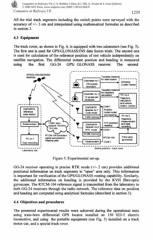
The track rover, as shown in Fig. 4, is equipped with two odometers (see Fig. 5).The first one is used for GPS/GLONASS/INS data fusion trials. The second oneis used for calculation of the reference position of test vehicle independently onsatellite navigation. The differential instant position and heading is measuredusing the first GG-24 GPS/ GLONASS receiver. The second
GPS/GLONASS/GNSSsatellites
DGPS/RTKreferencebase station
Laboratory siteMobile platform - track rover
Figure 5: Experimental set-up.
GG-24 receiver operating in precise RTK mode (+/- 2 cm) provides additionalpositional information on track segments in "open" area only. This informationis important for verification of the GPS/GLONASS routing capability. Similarly,the additional information on heading is provided by the KVH fibre-opticgyroscope. The RTCM-104 reference signal is transmitted from the laboratory toboth GG-24 receivers through the radio network. The reference data on positionand heading are computed using analytical formulas (described in section 3).
4.4 Objectives and procedures
The presented experimental results were achieved during the operational testsusing train-born differential GPS locator installed on 130 023-5 electriclocomotive, and using the portable equipment (see Fig. 5) installed on a trackmotor-car, and a special track rover.
Computers in Railways VII, C.A. Brebbia J.Allan, R.J. Hill, G. Sciutto & S. Sone (Editors) © 2000 WIT Press, www.witpress.com, ISBN 1-85312-826-0

Computers in Railways VII
Main attention was paid to the experimental verification of GG-24 routingdetection capability on the switch-points. Further, the observation of GPS andGLONASS satellite visibility, accuracy in position, and other parameters underdifferent conditions on tracks were investigated with respect to the futureapplications in signalling.
Two routing models have been experimentally investigated: two-dimensionaland one-dimensional. In the case of two-dimensional model, the track rover wasrunning over the switch-point, and its position measured by GG-24 receiver wasrecorded. The measured trajectory in code mode was compared with thecomputed reference trajectory.
Similarly, the instant heading in dependence of the travelled distance wasrecorded and compared with the reference heading calculated from the referencetrajectory. Heading data were also provided by KVH laser gyro with data rate of10 Hertz to verify its functionality for the routing detection. Since the GG-24receiver provides position in WGS-84 co-ordinate system, the data had to betransformed to x,y projection.
5 Experimental results
In this paper, there are presented the results illustrating the routing detection forthe following configurations: a) mixed mode (GPS+GLONASS) differentiallycorrected with the age of RTCM-104 corrections of 1 second, b) GPSdifferentially corrected with the age of RTCM-104 corrections of 50 seconds,and c) the instant heading provided by the fibre-optic gyroscope.
Excepting this, the advantage of the combined GPS/GLONASS receiver isdemonstrated in the case of the track surveying in the deep track cutting. Finally,the results concerning a number of received navigational satellites on track athilly areas on single-track lines and stations, and on double-track corridor linesare also presented.
5.1 Routing performance
The axis of the tracks entering/rising to/from the switch-point were surveyedusing DGPS and postprocessing with accuracy of +/- 2 cm and approximatedusing cubic polynomials to get the reference trajectory. The reference heading independence of the travelled distance was derived from the reference trajectory.However, there are very small differences between two boundary points of twoadjacent cubic parabolas, which ranging from 1 to 2 cm. Thus the referencetrajectory is not a continuous curve and some small step changes appear in thereference heading. However, the changes are negligible from the viewpoint ofthe verification methodology.
The time delay, which was intentionally introduced into the generation of theRTCM-104 correction signal by the reference GG-24 base station, simulates adegradation in the accuracy of the mobile receiver.
Computers in Railways VII, C.A. Brebbia J.Allan, R.J. Hill, G. Sciutto & S. Sone (Editors) © 2000 WIT Press, www.witpress.com, ISBN 1-85312-826-0

Computers in Railways VII
5.1.1 Two dimensional routing model - position measurement
1237
The positional data was selected from NMEA-183 GGA messages, which alsoinclude average number of received satellites (SV), PDOP, the age of corrections(t), etc. The parameters are described in each graph.
700
680
660
5,640
620
600
580
— referenceB-HD meas. track 1A--A meas. track 2
3496 3497 34983480 3485 3490 3495 3500 3505 3510 3515 3520 3525
x[m]
Figure 6: Measured position of the track rover at switch-point,(GPS+GLONASS, SV=10.5, PDOP=U, 1=1 s).
Figure 6 shows measured position of the track rover at the switch-pointaccording to the configuration a). The accuracy in position less then 1 meter wasachieved. As results from Tab. 1, it is possible to distinguish that the vehicle islocated on one of the parallel tracks with probability greater than 99.9999 % oftime. The measured trajectory according to configuration b) is in Fig. 7. Theaccuracy of the measured position was degraded to about 10 meters. Thisaccuracy is not sufficient the for train routing detection within the two-dimensional model. The age of the correction of 60 seconds degrades accuracy to15 meters level, and it is not applicable for the train routing at all.From other experiments, which are not graphically presented in this paper is
clear, that the age of corrections up to 15 s didn't introduce an observabledegradation of the GG-24 receiver accuracy in GPS mode. The age ofcorrections of 30 s degraded the accuracy to 2 meters. The age of RTCM-104corrections of 5 seconds is recommended in order to save radio channel capacity.
Computers in Railways VII, C.A. Brebbia J.Allan, R.J. Hill, G. Sciutto & S. Sone (Editors) © 2000 WIT Press, www.witpress.com, ISBN 1-85312-826-0
1238 Computers in Railways VII
700
680 -
660
-640 -
620
600
580
— referenceB—EI meas. track 1-̂-6 meas. track 2
3480 3485 3490 3495 3500 3505 3510 3515 3520 3525x[m]
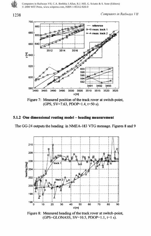
Figure 7: Measured position of the track rover at switch-point,(GPS, SV=7.63, PDOP=1.4, r=50 s).
5.1.2 One dimensional routing model - heading measurement
The GG-24 outputs the heading in NMEA-183 VTG message. Figures 8 and 9
10 20 30 40 50 60 70 80 90196
Figure 8: Measured heading of the track rover at switch-point,(GPS+GLONASS, SV=10.5, PDOP=1.1, t=l s).
Computers in Railways VII, C.A. Brebbia J.Allan, R.J. Hill, G. Sciutto & S. Sone (Editors) © 2000 WIT Press, www.witpress.com, ISBN 1-85312-826-0

Computers in Railways VII 1239
illustrate the measured heading by the GG-24 receiver according to theconfigurations a) and b), respectively. Figure 10 illustrates the measured
10 20 30 40 50 60 70 80196
Figure 9: Measured heading of the track rover at switch-point,(GPS mode, SV=7.63, PDOP=1.4, t=50 s).
100
Figure 10: Measured heading of the track rover at switch-pointusing KVH gyroscope.
heading using the KVH gyroscope. In case a) the measured heading isapplicable for the routing detection. If the age of corrections of 50 seconds was
Computers in Railways VII, C.A. Brebbia J.Allan, R.J. Hill, G. Sciutto & S. Sone (Editors) © 2000 WIT Press, www.witpress.com, ISBN 1-85312-826-0

1240 Computers in Railways Vll
introduced, which corresponds to about 10 meters in accuracy, the measuredheading was degraded too much it cannot be applicable for routing the detection(see Fig. 9). As results from other tests, the maximal age of corrections of 30seconds is acceptable for the routing detection. KVH gyro provides very goodreproducibility in the heading measurement on the switch, as shown in Fig. 10.
5.2 Satellite visibility along track
GPS receiver on a single-track line in flat area and passing through a forest canusually receive from 3 to 5 satellites. Sometimes, GPS receiver cannot calculate
1540
1535
1530
_1525E,>%1520
1515
1510
1505
trackB—-a GPS+GLONASSA—-A GPS
•-. r—r3660 3665 3670 3675 3680 3685 3690 3695 3700
x[m]
Figure 11: The difference between track surveying using GPS andGPS+GLONASS (GPS SV-4.5, GPS+GLONAS SV-7.5).
position (only 2 or 3 satellites visible), or the differentially corrected position isdegraded from 1 meter to several tenths of meters. If the satellite signal isblocked by trees without leafs, the GPS receiver can receive signal from 2 to 3more satellites. The situation is nearly the same at hilly areas with deep trackcuttings and high hillsides along the track. However, there are more sites ontrack where GPS receiver cannot calculate position. GLONASS usually addfrom 1 to 3 visible satellites.
At stations, where yard area is wider and sky more open than a forest path onesingle-track line, 6 or more GPS satellites are visible. The situation is practicallythe same at stations at flat or hilly areas. GLONASS again add from 1 to 4. It isthe important fact for the detection of train routing. On double track corridorlines the satellite visibility is nearly the same as at stations.
Although, the current GLONASS constellation consists of 11 operationalsatellites only, its effect is still positive in railway applications. Mainly for tracksurveying in deep track cuttings, as illustrates Fig. 11.
Computers in Railways VII, C.A. Brebbia J.Allan, R.J. Hill, G. Sciutto & S. Sone (Editors) © 2000 WIT Press, www.witpress.com, ISBN 1-85312-826-0

Computers in Railways VII i 241
6 Conclusion
The experimental results presented in this paper show that signalling and otherrailway safety critical applications require GPS receiver with accuracy of 1meter. This receiver provides both the positional and the heading information,which can be used for detection of train routing at switch-points. Excepting this,other railway applications require 1 meter accuracy for train positiondetermination, such as shunting operations and precise train stopping controlalong a platform.
A stand alone one-dimensional routing detection model [1] is rejected in thispaper. GPS receiver accuracy of 10 meters is not able to provide reliableinformation on heading for signalling applications. On the other hand it isrecommended to employ a combination of one and two-dimensional models forGPS and INS integration. However, GPS receiver with accuracy of 1 meter mustbe used.
It is clear that current GPS and GLONASS don't meet safety requirements. Inspite of this satellite systems are sufficient for current development of railwaysafety related applications, which will be based on GALILEO system in thefuture. Which basic railway safety related requirements should GALILEOsatisfy?
First, it is clear that current coverage by the signal from GPS/GLONASSsatellites is not sufficient to meet railway safety requirements. The GNSS-1 willbe put in operation this year but doesn't solve the problems with the coverage.Although the final constellation of new GALILEO system hasn't been definedyet. It should bring at least 24 new navigational satellites. Under thesepresumptions it is evident that GPS receiver on train will be able to receive atleast 6 satellites on single-track line. The same receiver will be able to receive atleast 12 satellites on yards. It is sufficient number to detect train routing.Together with the additional inertial sensors, obviously.
Although GNSS-1 with EGNOS overlay satellite system is able to providedifferential corrections through the satellite link, this function doesn't seemcritical in railway safety-related applications. The RTCM-104 correction signalcan be transmitted from a ground GPS reference station to the trains throughtrain radio data network, which is necessary for other signalling functions. Thedata quantity in the RTCM-104 message is 380 Bytes in worst case and it can becompressed to about half. If the compressed message will be sent to each trainevery 5 seconds, as it proposed in section 5.1.1, there is a capacity enough toperform other signalling functions. The efficiency of the distribution of thecorrection signal via satellite link (GNSS-1) will be experimentally investigatedwithin DG-XIII's APOLO project at RENFE and CD this year.
CD has already specified the other safety-related parameters for GALILEOsystem. The parameters are the following: availability greater than 99.99%,integrity risk at least 3.0"̂ [I/ hour], continuity risk 4.0~̂ /30 second, time-to alarmless then 1 second. Future GALILEO providers should guarantee the safetyrelated-parameters to railway end-users within a special service.
Computers in Railways VII, C.A. Brebbia J.Allan, R.J. Hill, G. Sciutto & S. Sone (Editors) © 2000 WIT Press, www.witpress.com, ISBN 1-85312-826-0
I ~>42 Computers in Railways Vll
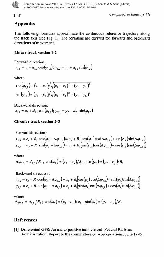
Appendix
The following formulas approximate the continuous reference trajectory alongthe track axis (see Fig. 1). The formulas are derived for forward and backwarddirections of movement.
Linear track section 1-2
Forward direction:
where
,3 )
Backward direction:
*2,i = *2 + ̂2,1 cos(#J; ̂ ,i
Circular track section 2-3
Forward direction :
*2,3 = ̂ + *i cos(̂
2̂,3 =Cy +R^ sin(̂ 2
where
Backward direction :
2)=
where
References
[1] Differential GPS: An aid to positive train control. Federal RailroadAdministration, Report to the Committees on Appropriations, June 1995.
Computers in Railways VII, C.A. Brebbia J.Allan, R.J. Hill, G. Sciutto & S. Sone (Editors) © 2000 WIT Press, www.witpress.com, ISBN 1-85312-826-0