coms/csee 4140 networking laboratory lecture 03 salman abdul baset spring 2008
Post on 20-Dec-2015
217 views
TRANSCRIPT

COMS/CSEE 4140 Networking Laboratory
Lecture 03
Salman Abdul BasetSpring 2008
2
Announcements No prelab due next week. Instead a small
assignment. Due next week for all students.
Lab 3 will be covered over two weeks. Lab 3 (1-4) due next week before your lab
slot.

3
Previous lecture… Data Link Protocols
Topology: bus, ring, star Ethernet and 802.3 (bus and star topology)
CSMA/CD Ethernet/802.3, CSMA/CA 802.11 (WiFi) Switch and hub PPP protocol
Address Resolution Protocol (ARP) Proxy ARP, RARP, ARP cache, vulnerabilities
IP addresses Structure, classful IP addresses, CIDR,
subnetting, IPv6

4
Agenda More on CIDR Internet Protocol (IP) Internet Control Message Protocol (ICMP) IP forwarding Router architecture

5
Classless Inter-domain routing (CIDR) 1993 Full description RFC 1518 & 1519
Network prefix is of variable length
Addresses are allocated hierarchically
Routers aggregate multiple address prefixes into one routing entry to minimize routing table size

6
CIDR notation CIDR notation of an IP address:
128.143.137.144/24 /24 is the prefix length. It states that the first 24 bits
are the network prefix of the address (and the remaining 8 bits are available for specific host addresses)
CIDR notation can nicely express blocks of addresses An address block
[128.195.0.0, 128.195.255.255] can be represented by an address prefix 128.195.0.0/16
How many addresses are there in a /x address block? 2 (32-x)

7
CIDR hierarchical address allocation
IP addresses are hierarchically allocated. An ISP obtains an address block from a Regional Internet Registry An ISP allocates a subdivision of the address block to an organization An organization recursively allocates subdivision of its address block
to its networks A host in a network obtains an address within the address block
assigned to the network
ISP128.0.0.0/8
128.1.0.0/16
Foo.com
128.2.0.0/16
Library CS
128.59.0.0/16
128.59.44.0/24 128.59.16.0/24
University
Bar.com
128.59.16.150

8
Regional Internet Registries (RIRs)
Registration and management of IP address is done by Regional Internet Registries (RIRs)
Where do RIRs get their addresses from: IANA maintains a high-level registry that distributes large blocks to RIRs
RIR are administer allocation of: IPv4 address blocks IPv6 address blocks Autonomous system (AS) numbers
There are currently five RIRs worldwide: APNIC (Asia/Pacific Region), ARIN (North America and Sub-Sahara Africa), LACNIC (Latin America and some Caribbean Islands) RIPE NCC (Europe, the Middle East, Central Asia, and African
countries located north of the equator). AfriNIC (Africa) (100,663,296 IP addresses 5% of total IPv4
addresses!)

9
Hierarchical address allocation
ISP obtains an address block 128.0.0.0/8 [128.0.0.0, 128.255.255.255]
ISP allocates 128.59.0.0/16 ([128.59.0.0, 128.59.255.255]) to the university.
University allocates 128.59.16.0/24 ([128.59.16.0, 128.59.16.255]) to the CS department’s network
A host on the CS department’s network gets one IP address 128.59.16.150
128.0.0.0 - 128.255.255.255
128.59.0.0 – 128.59.255.255
128.59.16.[0 – 255]128.59.16.150

10
CIDR allows route aggregation
ISP1 announces one address prefix 128.0.0.0./8 to ISP2 ISP2 can use one routing entry to reach all networks
connected to ISP1
ISP1128.0.0.0/8
128.1.0.0/16
Foo.com
128.2.0.0/16
Library CS
128.59.0.0/16
UniversityBar.com
IISP3
You can reach 128.0.0.0/8 via ISP1
128.0.0.0/8 ISP1

11
What problems CIDR does not solve
An multi-homing site still adds one entry into global routing tables
Mutil-home.com
128.0.0.0/8204.0.0.0/8
204.1.0.0/16
ISP2 ISP1
You can reach 128.0.0.0/8And 204.1.0.0/16 via ISP1
ISP3
204.1.0.0/16 ISP1204.1.0.0/16128.0.0.0/8 ISP1

12
Agenda More on CIDR Internet Protocol (IP) Internet Control Message Protocol (ICMP) IP forwarding Router architecture

13
IP: The waist of the hourglass IP is the waist of the
hourglass of the Internet protocol architecture
Multiple higher-layer protocols
Multiple lower-layer protocols
Only one protocol at the network layer.
Applications
HTTP FTP SMTP
TCP UDP
IP
Data link layer protocols
Physical layer protocols

14
Application protocol IP is the highest layer protocol which is
implemented at both routers and hosts
Application
TCP
IP
Data Link
Application
TCP
IP
NetworkAccess
Application protocol
TCP protocol
IP protocol IP protocol
DataLink
DataLink
IP
DataLink
DataLink
IP
DataLink
DataLink
DataLink
IP protocol
RouterRouter HostHost

15
IP Service Delivery service of IP is minimal
IP provide provides an unreliable connectionless best effort service (also called: “datagram service”). Unreliable: IP does not make an attempt to recover lost packets Connectionless: Each packet (“datagram”) is handled
independently. IP is not aware that packets between hosts may be sent in a logical sequence
Best effort: IP does not make guarantees on the service (no throughput guarantee, no delay guarantee,…)
Consequences:
• Higher layer protocols have to deal with losses or with duplicate packets
• Packets may be delivered out-of-sequence

16
IP supports the following services: one-to-one (unicast) one-to-all (broadcast) one-to-several (multicast)
IP multicast also supports a many-to-many service. IP multicast requires support of other protocols
(IGMP, multicast routing)
IP Service
unicastbroadcast multicast

17
20 bytes ≤ Header Size < 24 x 4 bytes = 60 bytes 20 bytes ≤ Total Length < 216 bytes = 65536 bytes
IP Datagram Format
ECNversionheaderlength
DS total length (in bytes)
Identification Fragment offset
source IP address
destination IP address
options (0 to 40 bytes)
payload
4 bytes
time-to-live (TTL) protocol header checksum
bit # 0 15 23 248 317 16
0MF
DF
3 4
18
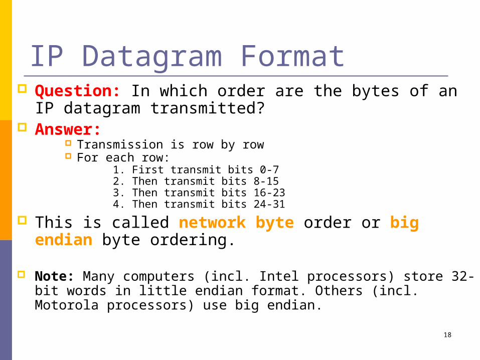
IP Datagram Format Question: In which order are the bytes of an IP
datagram transmitted? Answer:
Transmission is row by row For each row:
1. First transmit bits 0-72. Then transmit bits 8-153. Then transmit bits 16-234. Then transmit bits 24-31
This is called network byte order or big endian byte ordering.
Note: Many computers (incl. Intel processors) store 32-bit words in little endian format. Others (incl. Motorola processors) use big endian.

19
Big endian vs. little endian
Little Endian Stores the low-order byte at
the lowest address and the highest order byte in the highest address.
Base Address+0 Byte0 Base Address+1 Byte1 Base Address+2 Byte2 Base Address+3 Byte3
Intel processors use this order
Big Endian Stores the high-order byte at
the lowest address, and the low-order byte at the highest address.
Base Address+0 Byte3 Base Address+1 Byte2 Base Address+2 Byte1 Base Address+3 Byte0
Motorola processors use big endian.
• Conventions to store a multibyte data type• Example: a 4 byte Long Integer Byte3 Byte2 Byte1 Byte0

20
Fields of the IP Header Version (4 bits): current version is 4, next
version will be 6. Header length (4 bits): length of IP header, in
multiples of 4 bytes DS/ECN field (1 byte)
This field was previously called as Type-of-Service (TOS) field. The role of this field has been re-defined, but is “backwards compatible” to TOS interpretation
Differentiated Service (DS) (6 bits): Used to specify service level (currently not supported in the
Internet) Explicit Congestion Notification (ECN) (2 bits):
New feedback mechanism used by TCP

21
Fields of the IP Header Identification (16 bits): Unique
identification of a datagram from a host. Incremented whenever a datagram is transmitted
Flags (3 bits): First bit always set to 0 DF bit (Do not fragment) MF bit (More fragments) Will be explained later Fragmentation

22
Fields of the IP Header Time To Live (TTL) (1 byte):
Specifies longest paths before datagram is dropped
Role of TTL field: Ensure that packet is eventually dropped when a routing loop occurs
Used as follows: Sender sets the value (e.g., 64) Each router decrements the value by 1 When the value reaches 0, the datagram is
dropped

23
Fields of the IP Header Protocol (1 byte):
Specifies the higher-layer protocol. Used for demultiplexing to higher layers.
Header checksum (2 bytes): A simple 16-bit long checksum which is computed for the header of the datagram.
IP
1 = ICMP 2 = IGMP
6 = TCP 17 = UDP
4 = IP-in-IPencapsulation

24
Fields of the IP Header Options:
Security restrictions Record Route: each router that processes the packet adds its
IP address to the header. Typically never set. Why? Timestamp: each router that processes the packet adds its IP
address and time to the header. (loose) Source Routing: specifies a list of routers that must
be traversed. (strict) Source Routing: specifies a list of the only routers
that can be traversed.
Padding: Padding bytes are added to ensure that header ends on a 4-byte boundary

25
Maximum Transmission Unit Maximum size of IP datagram is 65535, but the data link
layer protocol generally imposes a limit that is much smaller
Example: Ethernet frames have a maximum payload of 1500 bytes
IP datagrams encapsulated in Ethernet frame cannot be longer than 1500 bytes
The limit on the maximum IP datagram size, imposed by the data link protocol is called maximum transmission unit (MTU)
MTUs for various data link protocols: Ethernet: 1500 FDDI: 4352802.3: 1492 ATM AAL5: 9180802.5: 4464 PPP: negotiated

26
IP Fragmentation
FDDIRing
RouterHost A Host B
Ethernet
MTUs: FDDI: 4352 Ethernet: 1500
• Fragmentation: • IP router splits the datagram into several datagram• Fragments are reassembled at receiver
What if the size of an IP datagram exceeds the MTU?IP datagram is fragmented into smaller units.
What if the route contains networks with different MTUs?

27
Where is Fragmentation done? Fragmentation can be done at the sender
or at intermediate routers The same datagram can be fragmented
several times. Reassembly of original datagram is only
done at destination hosts !!
Router
IP datagram H Fragment 1 H1Fragment 2 H2

28
What’s involved in Fragmentation? The following fields in
the IP header are involved:
Identification When a datagram is fragmented, the identification is the same in all fragments
Flags DF bit is set: Datagram cannot be fragmented and must
be discarded if MTU is too smallMF bit set: This datagram is part of a fragment and an
additional fragment follows this one
ECNversionheaderlength
DS total length (in bytes)
Identification Fragment offset
time-to-live (TTL) protocol header checksum
0MF
DF

29
What’s involved in Fragmentation? The following fields in
the IP header are involved:
Fragment offset Offset of the payload of the current fragment in the original datagram
Total length Total length of the current fragment
ECNversionheaderlength
DS total length (in bytes)
Identification Fragment offset
time-to-live (TTL) protocol header checksum
0MF
DF

30
Example of Fragmentation A datagram with size 2400 bytes must be
fragmented according to an MTU limit of 1000 bytes
IP datagram
Router
Fragment 2Fragment 3
MTU: 1000MTU: 4000
Fragment 1
Header length: 20
Total length: 2400
Identification: 0xa428
DF flag: 0
MF flag: 0
Fragment offset: 0
Header length: 20
Total length: 996
Identification: 0xa428
DF flag: 0
MF flag: 1
fragment offset: 0
Header length: 20
Total length: 996
Identification: 0xa428
DF flag: 0
MF flag: 1
Fragment offset: 122
Header length: 20
Total length: 448
Identification: 0xa428
DF flag: 0
MF flag: 0
Fragment offset: 244

31
Determining the length of fragments To determine the size of the fragments we recall that,
since there are only 13 bits available for the fragment offset, the offset is given as a multiple of eight bytes. As a result, the first and second fragment have a size of 996 bytes (and not 1000 bytes). This number is chosen since 976 is the largest number smaller than 1000–20= 980 that is divisible by eight. The payload for the first and second fragments is 976 bytes long, with bytes 0 through 975 of the original IP payload in the first fragment, and bytes 976 through 1951 in the second fragment. The payload of the third fragment has the remaining 428 bytes, from byte 1952 through 2379. With these considerations, we can determine the values of the fragment offset, which are 0, 976 / 8 = 122, and 1952 / 8 = 244, respectively, for the first, second and third fragment.

32
Agenda More on CIDR Internet Protocol (IP) Internet Control Message Protocol (ICMP) IP forwarding Router architecture

33
The IP (Internet Protocol) relies on several other protocols to perform necessary control and routing functions:
Control functions (ICMP) Multicast signaling (IGMP) Setting up routing tables (RIP, OSPF, BGP, …)
Control
Routing
ICMP IGMP
RIP OSPF BGP PIM
Overview

34
Overview The Internet Control Message Protocol (ICMP)
is a helper protocol that supports IP with facility for Error reporting Simple queries defined in RFC 792
ICMP messages are encapsulated as IP datagrams:
IP header ICMP message
IP payload

35
ICMP message format
additional informationor
0x00000000
type code checksum
bit # 0 15 23 248 317 16
4 byte header: Type (1 byte): type of ICMP message Code (1 byte): subtype of ICMP message Checksum (2 bytes): similar to IP header checksum.
Checksum is calculated over entire ICMP messageIf there is no additional data, there are 4 bytes set to zero.
each ICMP messages is at least 8 bytes long

36
ICMP Query message
ICMP query: Request sent by host to a router or host Reply sent back to querying host
Host
ICMP Request
Host or router
ICMP Reply

37
Example of ICMP QueriesType/Code: Description
8/0 Echo Request0/0 Echo Reply
13/0 Timestamp Request14/0 Timestamp Reply
10/0 Router Solicitation9/0 Router Advertisement
The ping command uses Echo Request/ Echo Reply

38
Ping’s are handled directly by the kernel Each Ping is translated into an ICMP Echo
Request The Ping’ed host responds with an ICMP
Echo Reply
Example of a Query: Echo Request and Reply
Hostor
Router
Hostor
Router
ICMP ECHO REQUESTHost or
router
Host or
router
ICMP ECH
O REPLY

39
Example of a Query: ICMP Timestamp A system (host or router)
asks another system for the current time.
Time is measured in milliseconds after midnight UTC (Universal Coordinated Time) of the current day
Sender sends a request, receiver responds with reply Type
(= 17 or 18)Code(=0)
Checksum
32-bit sender timestamp
identifier sequence number
32-bit receive timestamp
32-bit transmit timestamp
Sender Sender
ReceiverReceiver
TimestampRequest
TimestampReply

40
ICMP Error message
ICMP error messages report error conditions Typically sent when a datagram is discarded Error message is often passed from ICMP to
the application program
Host
IP datagram
Host or router
ICMP ErrorMessage
IP datagramis discarded

41
ICMP Error message
ICMP error messages include the complete IP header and the first 8 bytes of the payload (typically: UDP, TCP)
Unused (0x00000000)
IP header ICMP header IP header 8 bytes of payload
ICMP Message
from IP datagram that triggered the error
type code checksum

42
Frequent ICMP Error message
Type Code Description
3 0–15 Destination unreachable
Notification that an IP datagram could not be forwarded and was dropped. The code field contains an explanation.
5 0–3 Redirect Informs about an alternative route for the datagram and should result in a routing table update. The code field explains the reason for the route change.
11 0, 1 Time exceeded
Sent when the TTL field has reached zero (Code 0) or when there is a timeout for the reassembly of segments (Code 1)
12 0, 1 Parameterproblem
Sent when the IP header is invalid (Code 0) or when an IP header option is missing (Code 1)

43
Some subtypes of the “Destination Unreachable”
Code Description Reason for Sending
0 Network Unreachable
No routing table entry is available for the destination network.
1 Host Unreachable
Destination host should be directly reachable, but does not respond to ARP Requests.
2 Protocol Unreachable
The protocol in the protocol field of the IP header is not supported at the destination.
3 Port Unreachable
The transport protocol at the destination host cannot pass the datagram to an application.
4 Fragmentation Needed and DF Bit Set
IP datagram must be fragmented, but the DF bit in the IP header is set.

44
Example: ICMP Port Unreachable RFC 792: If, in the destination host, the IP module cannot
deliver the datagram because the indicated protocol module or process port is not active, the destination host may send a destination unreachable message to the source host.
Scenario:
Client Client
Request a serviceat a port 80
Server Server
No process is waiting at port 80
Port
Unreacha
ble

45
Agenda More on CIDR Internet Protocol (IP) Internet Control Message Protocol (ICMP) IP forwarding Router architecture

46
Tenets of end-to-end delivery of datagramsThe following conditions must hold so that an IP
datagram can be successfully delivered
1. The network prefix of an IP destination address must correspond to a unique data link layer network (=LAN or point-to-point link or switched network). (The reverse need not be true!)
2. Routers and hosts that have a common network prefix must be able to exchange IP datagrams using a data link protocol (e.g., Ethernet, PPP)
3. Every data link layer network must be connected to at least one other data link layer network via a router.

47
Routing tables Each router and each host keeps a routing table which tells the
router how to process an outgoing packet Main columns:
1. Destination address: where is the IP datagram going to?2. Next hop: how to send the IP datagram?3. Interface: what is the output port?
Next hop and interface column can often be summarized as one column
Routing tables are set so that datagrams gets closer to the its destination
Destination NextHop
interface
10.1.0.0/2410.1.2.0/2410.2.1.0/2410.3.1.0/2420.1.0.0/1620.2.1.0/28
directdirectR4direct R4R4
eth0eth0serial0eth1eth0eth0
Routing table of a host or router
IP datagrams can be directly delivered (“direct”) or is sent to a router (“R4”)

48
Delivery with routing tables
D e s t i n a t i o n N e x t H o p 1 0 . 1 . 0 . 0 / 2 4 1 0 . 1 . 2 . 0 / 2 4 1 0 . 2 . 1 . 0 / 2 4 1 0 . 3 . 1 . 0 / 2 4 2 0 . 1 . 0 . 0 / 1 6 2 0 . 2 . 1 . 0 / 2 8
d i r e c t R 3 R 3 R 3 R 3 R 3
H 1
R 1 R 2
R 3 R 4
H 2
1 0 . 2 . 1 . 0 / 2 4
2 0 . 1 . 0 . 0 / 1 61 0 . 1 . 2 . 0 / 2 4
1 0 . 1 . 0 . 0 / 2 4 1 0 . 3 . 0 . 0 / 1 6
2 0 . 2 . 1 . 0 / 2 8
2 0 . 2 . 1 . 2 / 2 8
D e s t i n a t i o n N e x t H o p 1 0 . 1 . 0 . 0 / 2 4 1 0 . 1 . 2 . 0 / 2 4 1 0 . 2 . 1 . 0 / 2 4 1 0 . 3 . 1 . 0 / 2 4 2 0 . 1 . 0 . 0 / 1 6 2 0 . 2 . 1 . 0 / 2 8
d i r e c t d i r e c t R 4 d i r e c t R 4 R 4
D e s t i n a t i o n N e x t H o p 1 0 . 1 . 0 . 0 / 2 4 1 0 . 1 . 2 . 0 / 2 4 1 0 . 2 . 1 . 0 / 2 4 1 0 . 3 . 1 . 0 / 2 4 2 0 . 1 . 0 . 0 / 1 6 2 0 . 2 . 1 . 0 / 2 8
R 3 R 3 R 2 d i r e c t d i r e c t R 2
D e s t i n a t i o n N e x t H o p 1 0 . 1 . 0 . 0 / 2 4 1 0 . 1 . 2 . 0 / 2 4 1 0 . 2 . 1 . 0 / 2 4 1 0 . 3 . 1 . 0 / 2 4 2 0 . 2 . 0 . 0 / 1 6 3 0 . 1 . 1 . 0 / 2 8
R 3 d i r e c t d i r e c t R 3 R 2 R 2
D e s t i n a t i o n N e x t H o p 1 0 . 1 . 0 . 0 / 2 4 1 0 . 1 . 2 . 0 / 2 4 1 0 . 2 . 1 . 0 / 2 4 1 0 . 3 . 1 . 0 / 2 4 2 0 . 1 . 0 . 0 / 1 6 2 0 . 2 . 1 . 0 / 2 8
R 1 R 1 d i r e c t R 4 d i r e c t d i r e c t
D e s t i n a t i o n N e x t H o p 1 0 . 1 . 0 . 0 / 2 4 1 0 . 1 . 2 . 0 / 2 4 1 0 . 2 . 1 . 0 / 2 4 1 0 . 3 . 1 . 0 / 2 4 2 0 . 1 . 0 . 0 / 1 6 2 0 . 2 . 1 . 0 / 2 8
R 2 R 2 R 2 R 2 R 2 d i r e c t
to:20.2.1.2

49
Delivery of IP datagrams There are two distinct processes to delivering IP
datagrams:1. Forwarding: How to pass a packet from an input interface to the output interface? 2. Routing: How to find and setup the routing tables?
Forwarding must be done as fast as possible: on routers, is often done with support of hardware on PCs, is done in kernel of the operating system
Routing is less time-critical On a PC, routing is done as a background process

50
Processing of an IP datagram in IPUDP TCP
Inputqueue
Lookup nexthop
RoutingProtocol
Destinationaddress local?
Staticrouting
Yes
Senddatagram
IP forwardingenabled?
No
Discard
Yes No
Demultiplex
routingtable
IP module
Data Link Layer
IP router: IP forwarding enabledHost: IP forwarding disabled

51
Processing of an IP datagram in IP Processing of IP datagrams is very similar on an IP
router and a host Main difference:
“IP forwarding” is enabled on router and disabled on host
IP forwarding enabled if a datagram is received, but it is not for the local system, the datagram will be sent to a different system
IP forwarding disabled if a datagram is received, but it is not for the local system, the datagram will be dropped

52
Processing of an IP datagram at a router
1. IP header validation2. Process options in IP header3. Parsing the destination IP address 4. Routing table lookup5. Decrement TTL 6. Perform fragmentation (if
necessary)7. Calculate checksum8. Transmit to next hop9. Send ICMP packet (if necessary)
Receive an IP datagram

53
Routing table lookup When a router or host
need to transmit an IP datagram, it performs a routing table lookup
Routing table lookup: Use the IP destination address as a key to search the routing table.
Result of the lookup is the IP address of a next hop router, and/or the name of a network interface
Destination address
Next hop/interface
network prefixor
host IP addressor
loopback addressor
default route
IP address of next hop router
or
Name of a network interface
54
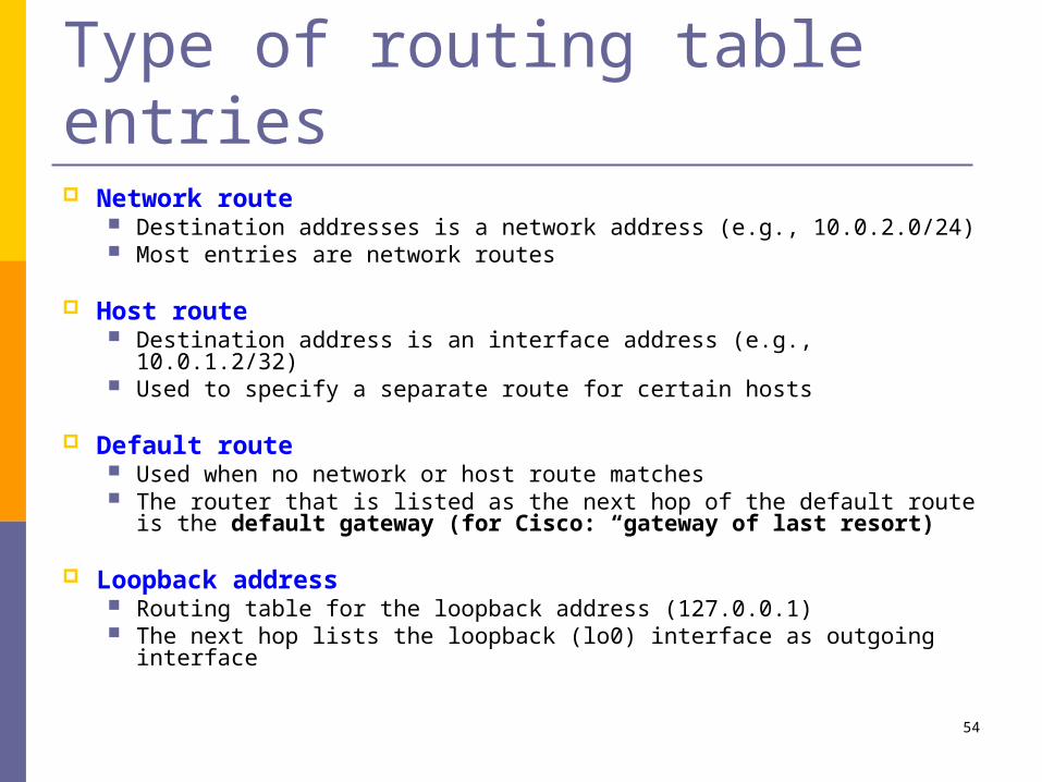
Type of routing table entries Network route
Destination addresses is a network address (e.g., 10.0.2.0/24) Most entries are network routes
Host route Destination address is an interface address (e.g., 10.0.1.2/32) Used to specify a separate route for certain hosts
Default route Used when no network or host route matches The router that is listed as the next hop of the default route is
the default gateway (for Cisco: “gateway of last resort)
Loopback address Routing table for the loopback address (127.0.0.1) The next hop lists the loopback (lo0) interface as outgoing
interface

55
Destination address Next hop
10.0.0.0/8 128.143.0.0/16 128.143.64.0/20 128.143.192.0/20 128.143.71.0/24 128.143.71.55/32
default
R1 R2 R3 R3 R4 R3 R5
Routing table lookup: Longest Prefix Match
128.143.71.21
The longest prefix match for 128.143.71.21 is for 24 bits with entry 128.143.71.0/24
Datagram will be sent to R4
Longest Prefix Match: Search for the routing table entry that has the longest match with the prefix of the destination IP address
1. Search for a match on all 32 bits2. Search for a match for 31 bits …..32. Search for a mach on 0 bits
Host route, loopback entry 32-bit prefix match
Default route is represented as 0.0.0.0/0 0-bit prefix match

56
Route Aggregation Longest prefix match algorithm permits to
aggregate prefixes with identical next hop address to a single entry
This contributes significantly to reducing the size of routing tables of Internet routers
Destination Next Hop
10.1.0.0/2410.1.2.0/2410.2.1.0/2410.3.1.0/2420.0.0.0/8
R3directdirect
R3R2
Destination Next Hop
10.1.0.0/2410.1.2.0/2410.2.1.0/2410.3.1.0/2420.2.0.0/1620.1.1.0/28
R3directdirect
R3R2R2

57
How do routing tables get updated? Adding an interface:
Configuring an interface eth2 with 10.0.2.3/24 adds a routing table entry:
Adding a default gateway: Configuring 10.0.2.1 as the
default gateway adds the entry:
Static configuration of network routes or host routes
Update of routing tables through routing protocols
ICMP messages
Destination Next Hop/interface
10.0.2.0/24 eth2
Destination Next Hop/interface
0.0.0.0/0 10.0.2.1

58
Destination Next Hop 10.1.0.0/24 …
R2
Destination Next Hop 10.1.0.0/24 …
R1
Ethernet
H1
R1 R2
Routing table manipulations with ICMP When a router detects that an IP
datagram should have gone to a different router, the router (here R2)
forwards the IP datagram to the correct router sends an ICMP redirect message to the host
Host uses ICMP message to update its routing table
(1) IP datagram
R1
(2) IP datagram
(3) ICMP redirect

59
ICMP Router SolicitationICMP Router Advertisement
After bootstrapping a host broadcasts an ICMP router solicitation.
In response, routers send an ICMP router advertisement message
Also, routers periodically broadcast ICMP router advertisement
This is sometimes called the Router Discovery Protocol
Ethernet
H1
R1 R2
ICMP routeradvertisement
ICMP routeradvertisement
ICMP routersolicitation

60
Agenda More on CIDR Internet Protocol (IP) Internet Control Message Protocol (ICMP) IP forwarding Router architecture

61
Router Components Hardware components of a
router: Network interfaces Interconnection network Processor with a memory and
CPU
PC router: interconnection network is the
(PCI) bus and interface cards are NICs
All forwarding and routing is done on central processor
Commercial routers: Interconnection network and
interface cards are sophisticated Processor is only responsible for
control functions (route processor)
Almost all forwarding is done on interface cards
Interface Card
Interconnection Network
Interface Card Interface Card
Processor
CPUMemory

62
Functional Components
Control
Datapath:per-packet processing
routingtable
Routingfunctions
IPForwarding
routing tablelookup
routing tableupdates
incoming IPdatagrams
outgoing IPdatagrams
routingprotocol
routingprotocol

63
Routing and ForwardingRouting functions include:
route calculation maintenance of the routing table execution of routing protocols
On commercial routers handled by a single general purpose processor, called route processor
IP forwarding is per-packet processing On high-end commercial routers, IP forwarding is
distributed Most work is done on the interface cards

64
Slotted Chassis
Large routers are built as a slotted chassis Interface cards are inserted in the slots Route processor is also inserted as a slot
This simplifies repairs and upgrades of components

65
Evolution of Router Architectures Early routers were essentially general purpose
computers Today, high-performance routers resemble
supercomputers Exploit parallelism Special hardware components
Until 1980s (1st generation): standard computer Early 1990s (2nd generation): delegate to
interfaces Late 1990s (3rd generation): Distributed architecture
Today: Distributed over multiple racks

66
1st Generation Routers This architecture is still used in
low end routers
Arriving packets are copied to main memory via direct memory access (DMA)
Interconnection network is a backplane (shared bus)
All IP forwarding functions are performed in the central processor.
Routing cache at processor can accelerate the routing table lookup.
Drawbacks: Forwarding Performance is
limited by CPU Capacity of shared bus limits the
number of interface cards that can be connected
Memory
Shared Bus
DMA
MAC
DMA
MAC
InterfaceCard
DMA
MAC
Route Processor
InterfaceCard
InterfaceCard
CacheCPU

67
SharedBus
InterfaceCards
DMA
MAC
DMA
MAC
DMA
MAC
Route Cache
Memory
Route Cache
Memory
Route Cache
Memory
Route Processor
MemoryCacheCPU
2nd Generation Routers Keeps shared bus
architecture, but offloads most IP forwarding to interface cards
Interface cards have local route cache and processing elements
Fast path: If routing entry is found in local cache, forward packet directly to outgoing interface
Slow path: If routing table entry is not in cache, packet must be handled by central CPU
Drawbacks: Shared bus is still bottleneck
slow path
fast path

68
CPU
Cache
Memory
MAC MAC
Memory
Forwarding Bus(IP headers only)
InterfaceCards
Data Bus
Control Bus
Memory
MAC
Memory
ForwardingEngine
CPU
Cache
Memory
ForwardingEngine
Route Processor
CPU
Memory
Another 2nd Generation Architecture IP forwarding is done by
separate components (Forwarding Engines)
Forwarding operations:
1. Packet received on interface: Store the packet in local memory. Extracts IP header and sent to one forwarding engine
2. Forwarding engine does lookup, updates IP header, and sends it back to incoming interface
3. Packet is reconstructed and sent to outgoing interface.

69
3rd Generation Architecture Interconnection network is a
switch fabric (e.g., a crossbar switch)
Distributed architecture: Interface cards operate
independent of each other No centralized processing for
IP forwarding
These routers can be scaled to many hundred interface cards and to aggregate capacity of > 1 Terabit per second
CPU
Memory
RouteProcessor
Memory
RouteProcessing
MAC
SwitchFabric
Interface
SwitchFabric
Memory
RouteProcessing
MAC
SwitchFabric
Interface

70
Basic Architectural ComponentsPer-packet processing
RoutingDecision
ForwardingDecision
ForwardingDecision
RoutingTable
RoutingTable
RoutingTable
Switch Fabric
OutputScheduling

71
Cisco 2621XM Router

72
Router commands PDF file

73
Lab this week… Lab 3 (1-4) Common errors
echo 1 > /proc/sys/net/ipv4/ip_forward How to proceed?
Reboot machines. Wait for graphical system to start before you switch to other machine.
Connect the cables. Configure IP addresses and perform the ping test. Interface does not work: change cable, then try other
interface, then ask TA. Do not reboot routers in this lab.
Three persons in a group One person attaches the cables The other person(s) configure IP addresses / routes on
separate machines