con · el game design - the class hierarc h y - whic pro vides b oth libraries and standard classes...
TRANSCRIPT

VOID Shell Speci�cation
Vinny Cahill, Andrew Condon, Dermot Kelly, Stephen
McGerty, Karl O'Connell, Gradimir Starovic, Brendan
Tangney
Distributed Systems Group,
Department of Computer Science,
Trinity College,
Dublin 2,Ireland.
Abstract
This document gives the speci�cation of the VOID Shell described in the
previous deliverables 1.2.1 and 1.3.1
An overview of the document is given followed by chapters on; the state chart
tool for game design; the implementation of events and the object model
(ECO); the class hierarchy for game development.
Document Identi�er MOONLIGHT Deliverable 1.5.1
Document Status ACCEPTED
Created 14 February 1995
Revised 31 March 1995
Distribution PUBLICc 1995 TCD DSG
Permission to copy without fee all or part of this material is granted provided that the TCD
copyright notice and the title of the document appear. To otherwise copy or republish requires
explicit permission in writing from TCD.
Contents
1 Document Summary 4
1.1 Introduction : : : : : : : : : : : : : : : : : : : : : : : : : : : : : : : : : : : : : : : : 4
1.2 The Entity Editor : : : : : : : : : : : : : : : : : : : : : : : : : : : : : : : : : : : : 4
1.3 Implementing the Object Model : : : : : : : : : : : : : : : : : : : : : : : : : : : : : 5
1.4 The VOID Libraries : : : : : : : : : : : : : : : : : : : : : : : : : : : : : : : : : : : : 6
2 Entity Editor Interfaces 8
2.1 Introduction : : : : : : : : : : : : : : : : : : : : : : : : : : : : : : : : : : : : : : : : 8
2.2 Entities : : : : : : : : : : : : : : : : : : : : : : : : : : : : : : : : : : : : : : : : : : 9
2.2.1 Objects and Entities : : : : : : : : : : : : : : : : : : : : : : : : : : : : : : : 9
2.2.2 Virtual World Entities : : : : : : : : : : : : : : : : : : : : : : : : : : : : : : 10
2.2.3 Assumptions about the Object Model : : : : : : : : : : : : : : : : : : : : : 10
2.2.4 Entity Structure : : : : : : : : : : : : : : : : : : : : : : : : : : : : : : : : : 10
2.2.4.1 Attributes : : : : : : : : : : : : : : : : : : : : : : : : : : : : : : : 11
2.2.4.2 Actions : : : : : : : : : : : : : : : : : : : : : : : : : : : : : : : : : 11
2.2.4.3 State Machine : : : : : : : : : : : : : : : : : : : : : : : : : : : : : 11
2.2.4.4 Queue : : : : : : : : : : : : : : : : : : : : : : : : : : : : : : : : : : 12
2.2.5 Entity Operation : : : : : : : : : : : : : : : : : : : : : : : : : : : : : : : : : 12
2.2.6 Example Entity : : : : : : : : : : : : : : : : : : : : : : : : : : : : : : : : : : 12
2.2.7 State Based vs Attribute Based : : : : : : : : : : : : : : : : : : : : : : : : : 13
2.3 Statechart Notation : : : : : : : : : : : : : : : : : : : : : : : : : : : : : : : : : : : 13
2.3.1 Statecharts : : : : : : : : : : : : : : : : : : : : : : : : : : : : : : : : : : : : 13
2.3.2 Depth : : : : : : : : : : : : : : : : : : : : : : : : : : : : : : : : : : : : : : : 14
2.3.3 Orthogonality : : : : : : : : : : : : : : : : : : : : : : : : : : : : : : : : : : : 14
2.3.4 Broadcast Communication : : : : : : : : : : : : : : : : : : : : : : : : : : : : 15
2.3.5 State Transitions : : : : : : : : : : : : : : : : : : : : : : : : : : : : : : : : : 16
2.3.6 Unstable States : : : : : : : : : : : : : : : : : : : : : : : : : : : : : : : : : : 16
2.3.7 Non-determinism of Transitions : : : : : : : : : : : : : : : : : : : : : : : : : 17
2.3.8 Non-determinism of Execution Order : : : : : : : : : : : : : : : : : : : : : : 19
2.3.9 Legality of State Transitions : : : : : : : : : : : : : : : : : : : : : : : : : : 19
2.3.10 Default States : : : : : : : : : : : : : : : : : : : : : : : : : : : : : : : : : : 21
2.3.11 Histories : : : : : : : : : : : : : : : : : : : : : : : : : : : : : : : : : : : : : : 21
2.3.12 Example : : : : : : : : : : : : : : : : : : : : : : : : : : : : : : : : : : : : : : 21
2.4 Entity Editor Graphical User Interface : : : : : : : : : : : : : : : : : : : : : : : : : 22
2.4.1 Requirements : : : : : : : : : : : : : : : : : : : : : : : : : : : : : : : : : : : 22
2.4.2 Related Applications : : : : : : : : : : : : : : : : : : : : : : : : : : : : : : : 24
2.4.3 Application Window/Screen : : : : : : : : : : : : : : : : : : : : : : : : : : : 24
2.4.4 Menu bar : : : : : : : : : : : : : : : : : : : : : : : : : : : : : : : : : : : : : 25
2.4.4.1 File Menu : : : : : : : : : : : : : : : : : : : : : : : : : : : : : : : : 25
2.4.4.2 Edit Menu : : : : : : : : : : : : : : : : : : : : : : : : : : : : : : : 25
1

2.4.4.3 Search Menu : : : : : : : : : : : : : : : : : : : : : : : : : : : : : : 25
2.4.4.4 View Menu : : : : : : : : : : : : : : : : : : : : : : : : : : : : : : : 25
2.4.4.5 Project Menu : : : : : : : : : : : : : : : : : : : : : : : : : : : : : : 26
2.4.5 Project Window : : : : : : : : : : : : : : : : : : : : : : : : : : : : : : : : : 26
2.4.6 Entity Window : : : : : : : : : : : : : : : : : : : : : : : : : : : : : : : : : : 26
2.4.6.1 Graphical View : : : : : : : : : : : : : : : : : : : : : : : : : : : : 26
2.4.6.2 Hierarchical View : : : : : : : : : : : : : : : : : : : : : : : : : : : 28
2.4.6.3 Button Bar : : : : : : : : : : : : : : : : : : : : : : : : : : : : : : : 29
2.4.6.4 Transition Popup Window : : : : : : : : : : : : : : : : : : : : : : 29
2.4.6.5 Attributes Popup Window : : : : : : : : : : : : : : : : : : : : : : 30
2.4.6.6 Named Actions Popup Window : : : : : : : : : : : : : : : : : : : 30
2.4.7 Summary : : : : : : : : : : : : : : : : : : : : : : : : : : : : : : : : : : : : : 30
2.5 Entity De�nition File Format : : : : : : : : : : : : : : : : : : : : : : : : : : : : : : 30
2.5.1 Storage requirements : : : : : : : : : : : : : : : : : : : : : : : : : : : : : : : 31
2.5.2 File Format Philosophy : : : : : : : : : : : : : : : : : : : : : : : : : : : : : 32
2.5.3 Format Syntax : : : : : : : : : : : : : : : : : : : : : : : : : : : : : : : : : : 32
2.5.4 Grammar : : : : : : : : : : : : : : : : : : : : : : : : : : : : : : : : : : : : : 34
2.5.5 Example : : : : : : : : : : : : : : : : : : : : : : : : : : : : : : : : : : : : : : 35
2.6 Entity Editor Code Generator : : : : : : : : : : : : : : : : : : : : : : : : : : : : : : 37
2.6.1 Starting Point : : : : : : : : : : : : : : : : : : : : : : : : : : : : : : : : : : 37
2.6.2 No Reverse Engineering : : : : : : : : : : : : : : : : : : : : : : : : : : : : : 38
2.6.3 Basic Statechart to Code Mapping : : : : : : : : : : : : : : : : : : : : : : : 38
2.6.3.1 Direct Mappings : : : : : : : : : : : : : : : : : : : : : : : : : : : : 38
2.6.3.2 Event Handling : : : : : : : : : : : : : : : : : : : : : : : : : : : : 39
2.6.3.3 State Maintenance : : : : : : : : : : : : : : : : : : : : : : : : : : : 39
2.6.3.4 Scope in Actions and Constraints : : : : : : : : : : : : : : : : : : 40
2.6.4 Simple Example : : : : : : : : : : : : : : : : : : : : : : : : : : : : : : : : : 40
2.6.4.1 Depart-on Lists : : : : : : : : : : : : : : : : : : : : : : : : : : : : 41
2.6.4.2 C++/ECO Code : : : : : : : : : : : : : : : : : : : : : : : : : : : : 41
2.6.5 Depth : : : : : : : : : : : : : : : : : : : : : : : : : : : : : : : : : : : : : : : 43
2.6.6 Orthogonality : : : : : : : : : : : : : : : : : : : : : : : : : : : : : : : : : : : 45
2.6.7 Unstable states : : : : : : : : : : : : : : : : : : : : : : : : : : : : : : : : : : 46
2.6.8 Non-determinism : : : : : : : : : : : : : : : : : : : : : : : : : : : : : : : : : 47
2.6.9 Summary : : : : : : : : : : : : : : : : : : : : : : : : : : : : : : : : : : : : : 48
3 ECOlib: Support For Events, Constraints, and Objects 49
3.1 Introduction : : : : : : : : : : : : : : : : : : : : : : : : : : : : : : : : : : : : : : : : 49
3.1.1 Programming with events, constraints, and objects : : : : : : : : : : : : : : 49
3.1.2 Assumptions about the ECOlib environment : : : : : : : : : : : : : : : : : 50
3.2 The ECOlib interface : : : : : : : : : : : : : : : : : : : : : : : : : : : : : : : : : : : 51
3.2.1 The ECOLib internals : : : : : : : : : : : : : : : : : : : : : : : : : : : : : : 51
3.2.2 The primitives of the interface : : : : : : : : : : : : : : : : : : : : : : : : : 52
3.2.2.1 Priorities : : : : : : : : : : : : : : : : : : : : : : : : : : : : : : : : 55
3.2.3 The prede�ned events : : : : : : : : : : : : : : : : : : : : : : : : : : : : : : 55
3.3 Summary : : : : : : : : : : : : : : : : : : : : : : : : : : : : : : : : : : : : : : : : : 59
4 The VOID Libraries 60
4.1 Introduction : : : : : : : : : : : : : : : : : : : : : : : : : : : : : : : : : : : : : : : : 60
4.2 Contents : : : : : : : : : : : : : : : : : : : : : : : : : : : : : : : : : : : : : : : : : : 61
4.3 Structure of the libraries : : : : : : : : : : : : : : : : : : : : : : : : : : : : : : : : : 61
4.3.1 Rami�cations of multiple target platforms : : : : : : : : : : : : : : : : : : : 61
4.3.2 Rami�cations of functional divisions : : : : : : : : : : : : : : : : : : : : : : 61
2

4.4 Platform and products : : : : : : : : : : : : : : : : : : : : : : : : : : : : : : : : : : 61
4.5 Functionality : : : : : : : : : : : : : : : : : : : : : : : : : : : : : : : : : : : : : : : 62
4.6 Design diagrams : : : : : : : : : : : : : : : : : : : : : : : : : : : : : : : : : : : : : 63
4.6.1 Using inheritance for multi-platform support : : : : : : : : : : : : : : : : : 63
4.6.2 Generic types and simpli�ed interfaces : : : : : : : : : : : : : : : : : : : : : 63
4.7 Development Strategy : : : : : : : : : : : : : : : : : : : : : : : : : : : : : : : : : : 63
4.7.1 Object oriented design and programming : : : : : : : : : : : : : : : : : : : 64
4.7.2 Encapsulating existing libraries : : : : : : : : : : : : : : : : : : : : : : : : : 64
4.7.3 Applications : : : : : : : : : : : : : : : : : : : : : : : : : : : : : : : : : : : 66
4.8 Summary : : : : : : : : : : : : : : : : : : : : : : : : : : : : : : : : : : : : : : : : : 67
A Interfaces to the libraries 68
A.1 Graphics classes : : : : : : : : : : : : : : : : : : : : : : : : : : : : : : : : : : : : : : 68
A.1.1 Abstract Base Classes for graphics : : : : : : : : : : : : : : : : : : : : : : : 68
A.1.2 Graphics class instantiations for GUL : : : : : : : : : : : : : : : : : : : : : 68
B ECOsim: class support for event-based programming 84
B.1 Introduction : : : : : : : : : : : : : : : : : : : : : : : : : : : : : : : : : : : : : : : : 84
B.1.1 Motivation : : : : : : : : : : : : : : : : : : : : : : : : : : : : : : : : : : : : 84
B.2 ECOsim: the user interfaces : : : : : : : : : : : : : : : : : : : : : : : : : : : : : : : 85
B.2.1 Writing a program using events : : : : : : : : : : : : : : : : : : : : : : : : : 85
B.2.2 Creating events and entities using ECOsim : : : : : : : : : : : : : : : : : : 86
B.2.3 Writing programs which use entities and events : : : : : : : : : : : : : : : : 88
B.3 Design and Software Architecture of ECOsim : : : : : : : : : : : : : : : : : : : : : 88
B.3.1 ECOsim Implementation : : : : : : : : : : : : : : : : : : : : : : : : : : : : 90
B.4 Future work : : : : : : : : : : : : : : : : : : : : : : : : : : : : : : : : : : : : : : : : 92
C The ECO model: events + constraints + objects 93
C.1 Introduction : : : : : : : : : : : : : : : : : : : : : : : : : : : : : : : : : : : : : : : : 93
C.2 Objects, events, and constraints : : : : : : : : : : : : : : : : : : : : : : : : : : : : : 94
C.2.1 Declaring events : : : : : : : : : : : : : : : : : : : : : : : : : : : : : : : : : 95
C.2.2 Notify constraints : : : : : : : : : : : : : : : : : : : : : : : : : : : : : : : : 96
C.2.3 Pre and Post constraints : : : : : : : : : : : : : : : : : : : : : : : : : : : : : 96
C.2.4 Announcing events and subscribing to events : : : : : : : : : : : : : : : : : 97
C.2.5 Implementation : : : : : : : : : : : : : : : : : : : : : : : : : : : : : : : : : : 99
C.3 Examples : : : : : : : : : : : : : : : : : : : : : : : : : : : : : : : : : : : : : : : : : 100
C.4 Related work : : : : : : : : : : : : : : : : : : : : : : : : : : : : : : : : : : : : : : : 102
C.5 Conclusions, present state and future work : : : : : : : : : : : : : : : : : : : : : : : 104
3

Chapter 1
Document Summary
1.1 Introduction
This chapter gives an overview of the document. It explains the relationship to the earlier deliv-
erable [57] and to the other design documents that have been produced since then.
This document is divided into 3 main chapters each one describing one of the 3 main components
of VOID, namely the statechart tool - used in high level game design - the class hierarchy - which
provides both libraries and standard classes and ECOlib - the library which implements the novel
MOONLIGHT object model. A brief introduction to each chapter is given below.
Since the delivery of the last document [57] much work has been done on progressing the
design of VOID. Two major documents were produced after detailed consultation with the other
partners. One progressed the design of the statechart notation and the other the object model.
The important sections of these documents are incorporated into this deliverable in order that it
can stand as comprehensive design and speci�cation document in its own right. The sections in
question are x2.2 and x2.3 and appendix C.
Appendix A contains the full speci�cation of the current VOID libraries in the form of C++
header �les.
In order that progress not be delayed while waiting upon the completion of ECOlib - the
implementation of the object model - a simpli�ed single node no frills ECO simulator has been
written and is in current use in application development. ECOsim is described in appendix B
The following sections introduce the main chapters of the report.
1.2 The Entity Editor
The Entity Editor, referred to as the Entity Behaviour De�nition Tool in the previous deliverable,
is a tool for specifying Entity classes using statechart notation. An Entity is simply a high level
abstraction of an object. Entities exist in event based object models, such as that provided by
C++/ECO.
The most signi�cant di�culty in designing a notation to describe entity behaviour is achieving a
balance between its expressive power and its simplicity. The ideal notation would allow a designer,
with minimal programming skills, to quickly specify the behaviour of an entity at a high level.
Statecharts were chosen as the basic mechanism for describing behaviour. The state machine
triggers the execution of actions, which must be coded by the user.
The general structure of the Entity Editor is presented in �gure 2.1. As statecharts are graphical
in nature, a Graphical User Interface (GUI) is required. Statecharts are somewhere between
drawings and programs, so the GUI should adopt many of the standards set by typical drawing
programs and integrated compilers.
4

GUIFront-end
DefinitionEntity
File
CodeGenerator C++/ECO
Entity DefinitionGenerator
Figure 1.1: General structure of the Entity Editor.
The Entity De�nition Generator drives the GUI, and allows the user to create and edit the
Entities and their statecharts. It is also capable of saving and loading Entity classes, in the form
of an Entity De�nition File (EDF). This is purely a storage format, and is not intended to be used
for execution purposes.
To allow the Entity Editor to produce executable code, the EDF is read into a Code Generator,
which outputs compilable source code. While it would be desirable to make the whole process
language independent, initial designs only consider the C++/ECO case. This code can then be
compiled, linked and executed in the VOID execution environment.
It is commonly accepted that design and implementation occur in cycles. Initial implementation
of these proposals may result in changes to the design.
1.3 Implementing the Object Model
In the ECO model 1 objects communicate among themselves using events and constraints. An
event represents something that can happen, and it has name and zero or more parameters. The
name of an event allows the objects to refer to a speci�c event among all the events. The parameters
of an event have type (e.g., an integer or a character string). For the speci�c occurrence of an
event the parameters are instantiated with values. These values, together with the event name,
describe to the objects what happened, i.e., describe the speci�c occurrence of an event2.
An object encapsulates some data and some processing. An object can tell other objects about
something that happened, and it can react if it is told by other objects that something happened.
The former is accomplished by announcing an event, and the latter by binding a method of the
object to the required event. This binding can be dynamic, i.e., it is allowed to unbind a method
from an event. The same method can be bound to several events, and the same event can have
several methods (of the same or of di�erent objects) bound to it. A binding can be established
only if the signatures of the event and of the method match (if they have the same number of
parameters, and the types of the corresponding parameters are the same).
Constraints enable more exible event-method bindings and more exible processing of event
noti�cations. An object may conditionally be interested in some event: it is interested only if the
speci�c event parameter has a speci�c value or any value from a range of values when the event
is announced. This can be expressed using the so called Notify constraints. In addition to this,
1A fuller description of the model is given in appendix C.2In the following text we use \event" for both an event and an event occurrence. The context will indicate the
correct interpretation.
5

an object may decide, based on the object's local state when it is told about an event, that the
processing of the event should be postponed or even cancelled.
The ECOlib library implements a low-level runtime support for the events constraints and
objects. It maintains information about classes, objects, events and their occurrences, and infor-
mation about various bindings. It knows about a number of prede�ned events. The library itself
uses events. More about the ECO model, and a programming language syntax for this model, can
be found in Appendix C. The separation of functionality between the ECOlib and its client is
shown in Figure 3.1.
ECOlib
ECOlib client
- announces events: user-defined & pre-defined
- (un)subscribes from/to events
- processes events using: enqueue, dequeue, process_active, process_passive, discard_single, discard_all
- stores information about:
* classes, objects, methods
* events
* bindings (method - event)
- implements the primitives, - knows about pre-defined events, - implements event deliveries
Figure 1.2: Separation of functionality between the ECOlib and ECOlib client code.
1.4 The VOID Libraries
The VOID libraries are a a key part of the MOONLIGHT strategy for improving productivity in
the development of video-game and virtual world programs. The libraries provide a uni�ed and
consistent interface to the various kinds of functionality that are required, such as two and three
dimensional graphics, input control, detection of collision between entities in the virtual world and
so on.
The libraries are one of three parts to the uni�ed solution that TCD is proposing, the other
parts being:
� an Entity Editor tool capable of automatic generation of application code from a graphical
notation (statecharts);
� run-time support, called ECO, for event-based programming.
In the text below we describe the relationship between the VOID libraries and these other
components.
6

Relationship to Entity Editor One of the key points in our approach to rapid prototyping
of video games and virtual worlds is the use of a graphical notation to specify the behaviour of
the entities. The VOID libraries are the key to allowing these speci�cations to become prototypes:
they provide the code that is used to provide functionality for entities. By framing the various
underlying software packages (such as GUL) in a consistent, object-oriented C++ library the Entity
Editor tool will be able produce working programs automatically.
Relationship to ECO The VOID libraries are basically independent of (but compatible with)
the ECO library, at least in this initial release. In e�ect the VOID libraries and the ECOlib form
twin supports for the Entity Editor. This is because programs written using statecharts need the
event support provided by the ECOlib. If these event-based programs are video-games then they
will also require the functionality provided by the VOID libraries.
Relationship to ECOsim In this release of the libraries we include a library called ECOsim,
which contains some simple class-based support for event-based programming. The purpose of
this library is to allow development of programs using the libraries in advance of completion of the
ECO model.
The class support is neither particularly e�cient nor fully-featured, but it does o�er a signi�cant
advantage over programming in straight C++: namely that it is not straight C++. Programs
written using the standard models of invocation and named addressing of C++ will have a very
di�erent structure to those developed using events. Therefore, if code developed using the early
versions of the libraries is to be of any use subsequently it should be developed using an event-based
approach.
7

Chapter 2
Entity Editor Interfaces
2.1 Introduction
GUIFront-end
DefinitionEntity
File
CodeGenerator C++/ECO
Entity DefinitionGenerator
Figure 2.1: General structure of the Entity Editor.
The Entity Editor is a tool for specifying Entity classes using statechart notation. An Entity is
simply a high level abstraction of an object. Entities exist in event based object models, such as
that provided by C++/ECO.
The most signi�cant di�culty in designing a notation to describe entity behaviour is achieving a
balance between its expressive power and its simplicity. The ideal notation would allow a designer,
with minimal programming skills, to quickly specify the behaviour of an entity at a high level.
Statecharts were chosen as the basic mechanism for describing behaviour. The state machine
triggers the execution of actions, which must be coded by the user.
The general stucture of the Entity Editor is presented in �gure 2.1. As statecharts are graphical
in nature, a Graphical User Interface (GUI) is required. Statecharts are somewhere between
drawings and programs, so the GUI should adopt many of the standards set by typical drawing
programs and integrated compilers.
The Entity De�nition Generator drives the GUI, and allows the user to create and edit the
Entities and their statecharts. It is also capable of saving and loading Entity classes, in the form
of an Entity De�nition File (EDF). This is purely a storage format, and is not intended to be used
for execution purposes.
To allow the Entity Editor to produce executable code, the EDF is read into a Code Generator,
which outputs compilable source code. While it would be desirable to make the whole process
8

language independent, initial designs only consider the C++/ECO case. This code can then be
compiled, linked and executed in the VOID execution environment.
It is commonly accepted that design and implementation occur in cycles. Initial implementation
of these proposals may result in changes to the design.
2.2 Entities
The following is a discussion of the concepts underpinning the MOONLIGHT entity.
2.2.1 Objects and Entities
One should be aware of the distinction between the objects of the MOONLIGHT object model and
the entities de�ned by the MOONLIGHT Entity Editor using the statechart notation.
The object model is a relatively low level abstraction, and deals with the problem of supporting a
system with many objects communicatingwith one another by raising events. Just as C++ provides
an underlying model that supports C++ objects and message passing, the MOONLIGHT object
model supports MOONLIGHT objects and event raising.
Just as one can write programs in C++, one will be able to write programs using the MOON-
LIGHT object model. However, both these programming paradigms are relatively low level.
To build up to a higher level, the concept of an entity is introduced. These are similar to
objects, but support more advanced programming mechanisms.
Consider the typical process of converting a C program into an executable image. The C is
�rst compiled into assembly language, which is in turn assembled into an executable program. C
is very di�erent from assembly language, however the compiler establishes a mapping from one to
the other.
Similarly the MOONLIGHT Entity Editor should establish a mapping from the high level
description of an entity to the lower level concept of a MOONLIGHT object. In theory it should
be possible for the Entity Editor to produce code for any object model that supports events. So
in the initial design of the notation, only a limited number of assumptions are made about the
underlying object model.
The essential point is that entities are higher level abstractions than objects, which are easier to
work with. The user need not be concerned with the fact that entities are implemented as objects.
Similarly, it is possible to think in terms of objects, and ignore the concept of an entity altogether
- one would simply be programming at a lower level.
Objects
Entities
Virtual World Entities
Entities derived from the Moonlight
Active objects executing a state machine
with control over Attributes and Actions.
Capable of raising and detecting events
and of having local data variables.
base Virtual World Entity class.
Figure 2.2: Levels of abstraction.
9

2.2.2 Virtual World Entities
As described in the previous section, entities are a high level abstraction of objects. However, there
are some basic similarities between the two. Just as there are classes and instances of objects, there
are classes and instances of entities. The Entity Editor will produce descriptions of entity classes,
from which the VOID execution environment will create instances. In other words, the principles
of the entity-oriented paradigm are similar to the principles of the object-oriented paradigm.
Another similarity is the presence of inheritance. Entity classes can be derived from other
entity classes. For the purposes of VOID, a standard entity class hierarchy will be provided for
use by the game developer. One particular entity class will provide the basic facility of existence
in the Virtual World. Entity classes derived from this class will be considered as Virtual WorldEntity classes.
For example, one may de�ne a score-keeping entity, which simply counts the number of aliens
the player destroys. Such an entity does not exist in the Virtual World, and so its class is not
derived from the base Virtual World Entity class. It is simply an ordinary entity, that is acting as
a counter. However, the player and the alien entities do exist in the Virtual World, and so their
entity classes are derived from the base Virtual World Entity class.
So we now have the concept of an object, of an entity and of a special type of entity known as
a Virtual World entity (see Figure 2.2).
2.2.3 Assumptions about the Object Model
The underlying system is considered to be composed of objects capable of raising parameterised
events and responding to events generated by themselves or other objects. An object simply
declares interest in certain events, and the object environment guarantees it will be informed
whenever they are raised. If an object wishes to raise an event, it does not need to have any
knowledge of those objects that have registered interest in the event (see Figure 2.3). This is in
contrast to the traditional object model that requires an object to send messages to objects of
which it has direct knowledge.
Object C
Object B
Object D
Object A
Event X
Figure 2.3: Object broadcasting event.
The objects are instances of classes. Just as in C++, a class is simply a description of the local
data and methods of the objects that will be instantiated from the class. However, unlike C++,
the methods are conceptually invoked when an event is raised, and not when a message is passed
speci�cally to the object.
2.2.4 Entity Structure
Entities have four conceptual components (see Figure 2.4):
� Attributes, which contains the entity's user-de�nable variables.
10

� Actions, which can update attributes and raise events.
� State machine, which maintains the objects state and deals with the processing of events and
state transitions. It is made up of the statechart logic and the state variables.
� Event queue, which holds a sequenced list of events the object has declared an interest in,
and that have been raised.
EventsQueue
Attributes
ActionsState machine
Statechart logic
State variables
Figure 2.4: Conceptual internals of an entity.
2.2.4.1 Attributes
Attributes are variables that are private to an entity. They are de�ned by the user and can be
used just as a C++ programmer would use variables de�ned in a C++ class. If an entity class is
de�ned as having three Attributes (say Colour, XPosition and YPosition), then all instances of
that class will have these three attributes. Their current values are independent of the state of the
statechart.
2.2.4.2 Actions
An Action can perform a sequence of basic instructions; namely, the assignment of values to the
attributes of the entity and the raising of events. The only values available to the script are the
entity's attributes, the parameters of the action and the current state of the state machine.
In practice it is envisaged that the action will be a fragment of code of the underlying object
model language (in this case C++/ECO), and so all the standard constructs it supports will be
available.
Ideally though, it would be desirable to constrain the user to perform only assignment and event
raising. This would ensure that all the constructs for looping and conditional execution would be
represented by the statechart and not in the code of the actions.
In practise, two types of actions exist: named and direct. A direct Action is simply a fragment
of code which is associated with a transition between two states in the State machine. Such actions
are imbedded within the state machine. A named Action is much like a function. It is a fragment
of code with a name, which can be invoked from anywhere that the action is in scope.
2.2.4.3 State Machine
An entity's state machine is described by statecharts, the syntax of which will be examined later.
For the moment, consider it to be a standard state machine. In any given state, the entity is
11

interested in a particular set of events. The arrival of these events cause transitions to new states,
which might be concerned with a di�erent set of events.
Just as a traditional state machine determines whether a sequence of inputs is valid for that
particular machine (or more exactly, the language the machine is interpreting), event driven stat-
echarts determine valid sequences of events that the object can deal with. This is why our model
uses a queue to sequence the events.
The operation of the state machine is as follows: Once an event is detected at the head of the
event queue, a list is made of the state changes that it triggers. The event is then removed from
the head of the queue and the state changes are executed.
If it happens that the new state is not interested in the next event on the queue, then that
event simply causes no state changes, and is discarded. This is reasonable when one considers that
the basic purpose of the statechart is to describe valid sequences of events.
The state variables simply store the current state of the state machine. These variables are
quite di�erent in nature to the attributes described above. The attributes are de�ned explicitly by
the user, and are updated explicitly by the execution of actions. The state variables are de�ned
implicitly by the Entity Editor, depending on the statechart drawn by the user. While they are
visible to the user (to see the current state of the entity) they are modi�ed exclusively by the state
machine of the entity when transitions occur.
2.2.4.4 Queue
As mentioned already, the state machine determines a valid sequence of events to which the entity
can respond. Ideally, it would be possible to respond to each event instantaneously, and so no
queueing of events would be needed. However, since an event may trigger any number of actions,
each taking an indeterminant length of time to execute, the noti�cation of other events must be
queued while these actions are executing.
2.2.5 Entity Operation
The users perception of an entity is that it has a single thread of execution, which is constantly
waiting for the arrival of a relevant event. Once such an event arrives, the thread wakes up, causes
some state transition in the state machine, and possibly executes some actions as dictated by the
transitions. When the actions are �nished, the thread goes back to waiting for another event.
As already mentioned, the arrival of events is queued, so no event is missed or lost as a result of
executing some action while it arrived.
In e�ect the thread is executing a state machine whose inputs are events and whose outputs are
a sequence of actions to be executed. The fact that the same thread executes the state machine
as executes the actions means that no queued events are processed until the actions triggered by
the last event have been executed to completion.
2.2.6 Example Entity
Consider a very simple entity, as in Figure 2.5. This entity models the idea that a computer is
either `up' (working okay), or is `down' (has been switched o�). In addition, it keeps a count as to
the number of times that the computer has been `booted up' (turned on).
The designer of this entity would have speci�ed the simple statechart; de�ned the attribute
boots (the counter); and entered the code for the action Bootup. The Entity Editor would then
have examined the statechart and determined that one state variable, computer, which can hold
the value Up or Down, is required to hold the current state of the entity.
The statechart is like a map. It does not hold the current state, but it does dictate what state
transitions can occur, and what Actions they should trigger. It is the state variables that hold the
current state.
12

Queue
Bootup:
boots := boots+1computer
Down Upoff
on/Bootup
computer: Down
State variables
State chart
State machine Actions
Attributes
boots: 4
on
Figure 2.5: Example `Computer' Entity.
In the example, the state machine is in state Down and some other entity has just raised the
event on. The statechart indicates that in this situation the state should change to Up and action
Bootup should be executed. This increments the value of boots. So as a result of an event the
state of the entity is updated and an action is executed.
2.2.7 State Based vs Attribute Based
Note that the state of the state machine and the value of the attributes are quite independent
of one another. This means that our statechart model of an entity is state based, rather than
attribute based.
In other words, when an entity is in a particular state, it says nothing about the values of the
attributes. In e�ect, the states have no formal meaning, other than to indicate that some set of
events can be accepted at this point in the life cycle of the entity.
However, from an intuitive point of view, a state can have signi�cant meaning. The simple fact
that each state has a name means that a statechart can give a very good picture of what it does.
But brie y consider the merits of an attribute based system: If the notation allowed the user to
specify that in one state (x < 10) is true, and in another state (x >= 10) is true; then transitions
between states would occur depending on the value of x. However, while this may be a useful
facility in many situations it introduces data dependencies on state transitions. These would be
too time consuming to maintain in a soft real time environment, and so will not be supported.
2.3 Statechart Notation
This section describes the notation used in VOID to specify the state machine of an entity class.
Remember that the responsibility of the state machine is to specify what events trigger what
actions at each of the intuitive states of the entity's life cycle. The states have no formal meaning
in the context of the attributes of the entity.
2.3.1 Statecharts
The notation used by entities to represent their state machine is that of Statecharts, �rst introducedby David Harel in 1987 [32]. Harel lists the following advantages that statecharts have over their
more primitive cousins, State Transition Diagrams. Central to the criticism is the argument that
STDs do not scale well.
13

� State diagrams are \ at". They provide no natural notion of depth, hierarchy, or modularity,
and therefore do not support stepwise, top-down or bottom-up development.
� State diagrams are uneconomical when it comes to transitions. An event that causes the same
transition from a large number of states, such as a high-level interrupt, must be attached to
each of them separately resulting in an unnecessary multitude of arrows.
� States diagrams are extremely uneconomical when it comes to the number of states required,
especially if a separate state is used to represent each value that a variable can take on.
As the system under description grows linearly, the number of states grows exponentially,
and the conventional FSM formalism forces one to explicitly represent them all.
� Finally, state diagrams are inherently sequential in nature and do not cater for concurrency
in a natural way.
Harel goes on to describe statecharts as:
statecharts = state diagrams + depth+ orthogonality + broadcast communication (2.1)
Graphically, states are represented by rectangles with rounded edges. If a state has sub-states,
then a horizontal line divides the rectangle into two sections, one for the state's name and one for
the representation of its sub-states.
Transitions have a start state and an end state (which may be one and the same) and are
denoted by an arrow connecting two states.
Within a given entity class, all state names must be unique. This restriction does not apply to
transitions, which are labelled with the event and action that apply to it.
2.3.2 Depth
The primary addition to STDs that statecharts provide is to allow states to possess sub-states with
an XOR relationship. This enables groups of transitions in a STD, triggered by the same event,
to be speci�ed with a single transition in the corresponding statechart as illustrated in following
two diagrams.
The internal transitions obey an exclusive-or rule: thus in Figure 2.7 being in state P means
being in either state A, B or C but excludes being in more than one of them at once.
S A CBα αα
β β β
Figure 2.6: Replicated transitions in an STD
2.3.3 Orthogonality
The second improvement that statecharts bring to STDs is the ability to separate aspects of state
that have no inter-dependency. This prevents the combinatorial explosion of states that occurs
with STDs.
14
S A CB
P
α αα
β
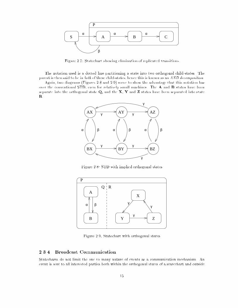
Figure 2.7: Statechart showing elimination of replicated transitions
The notation used is a dotted line partitioning a state into two orthogonal child-states. The
parent is then said to be in both of these child-states, hence this is known as an AND decomposition.Again, two diagrams (Figures 2.8 and 2.9) serve to show the advantage that this notation has
over the conventional STD, even for relatively small machines. The A and B states have been
separate into the orthogonal state Q, and the X, Y and Z states have been separated into state
R.
AX AY AZ
BY BZBX
α α αβ β β
γ
γγ
γ γ
γ
Figure 2.8: STD with implied orthogonal states
P
A
Y Z
X
B
γγ
γ
Q R
α β
Figure 2.9: Statechart with orthogonal states
2.3.4 Broadcast Communication
Statecharts do not limit the one to many nature of events as a communication mechanism. An
event is sent to all interested parties both within the orthogonal states of a statechart and outside
15

to other entities.
2.3.5 State Transitions
A state transition is a uni-directional path linking two states. It represents a potential change from
one state to another. The syntax of the annotations on the arrow of a transition are as follows:
Event(Event-Parameters)[Constraint]/Action(Action-Parameters)
Some examples are presented in Figure 2.10. The top example shows the general syntax.
The next example indicates that there is a transition from left to right when the Quit event
is detected. The next shows a parameterised event Add(n) triggering action Increment if the
constraint [n==1] is true. The �nal example shows a transition which invokes action MoveLeft(1)
when event JoystickLeft is detected.
All transitions from a stable state must be triggered by an event. The event parameters are
optional, depending on whether the event supports them. The optional constraint expression is
a function of the attributes, state variables and the event parameters. The optional action is
executed whenever the transition is traversed.
A transition is said to be active if the following are true:
� The state machine is in the source state of the transition.
� The event that triggers the transition is at the head of the entity's event queue.
� The constraint evaluates to true.
Once all the active transitions within the state machine have been identi�ed, the event is
removed from the head of the queue.
Then, for each state that has an active transition leaving it, the associated action is executed;
the source state is left; and the destination state is entered.
Note, if event parameters were to be mapped directly to action parameters, there would be the
limitation that only certain actions could be triggered by certain events.
Event(a,b...)[constraint]/Action(x,y,...)
Quit
Add(n) [n==1] / Increment
JoystickLeft / MoveLeft(1)
Figure 2.10: Examples of annotated transitions.
2.3.6 Unstable States
In order to allow sequencing, iteration and conditional execution of actions in response to a single
event, the concept of the unstable state is introduced. This is a state which is left the moment it
16

is entered. None of the transitions leaving it can be dependent on the raising of an event. The
notation uses a diamond within a state box to indicate that it is unstable. While the transitions
are not triggered by events, constraints can still be applied, and actions can still be triggered.
To force at least one transition to be active when in the unstable state, each unstable state
must have one completely unconstrained transition leaving it. This transition is only taken when
no other transition is active.
The simplest use of an unstable state is to ensure the sequencing of actions in response to an
event (see Figure 2.11). Here � triggers Action1, followed by Action2.
The unstable state also allows for the conditional movement from one state to one of many
other states in response to a single event (see Figure 2.12). Iteration is also possible, though this
introduces the possibility of in�nite loops (see Figure 2.13). Note that in this example there are
two transitions from state T to state B. One gives the speci�c exit condition for the loop, and
the other is the required unguarded transition for the unstable state. The guarded transition is
redundant in this case.
Aα
C/ Action1 / Action2
B
Figure 2.11: Single Event triggering sequence of actions using unstable states.
Unstable state
/DefaultAction
[x==1]/CaseOne
A [x==2]/CaseTwo
Z
Y
X
Tα / Init
Figure 2.12: Selection implemented using an unstable state.
Aα [x==10]
[x<10] / LoopAction
T B/ Init
x := x + 1
x := 0
Figure 2.13: Iteration implemented using an unstable state.
2.3.7 Non-determinism of Transitions
As with STDs, statecharts can have sets of transitions that are non-deterministic. For statecharts
Lucas [39] describes three categories: pure non-determinism, potential non-determinism and ap-
parent non-determinism.
17
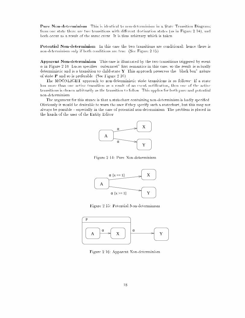
Pure Non-determinism This is identical to non-determinism in a State Transition Diagram:
from one state there are two transitions with di�erent destination states (as in Figure 2.14), and
both occur as a result of the same event. It is thus arbitrary which is taken.
Potential Non-determinism In this case the two transitions are conditional: hence there is
non-determinism only if both conditions are true. (See Figure 2.15)
Apparent Non-determinism This case is illustrated by the two transitions triggered by event
� in Figure 2.16. Lucas speci�es \outermost" �rst semantics in this case, so the result is actually
deterministic and is a transition to child-state Y. This approach preserves the \black box" nature
of state P and so is preferable. (See Figure 2.16)
The MOONLIGHT approach to non-deterministic state transitions is as follows: If a state
has more than one active transition as a result of an event noti�cation, then one of the active
transitions is chosen arbitrarily as the transition to follow. This applies for both pure and potential
non-determinism.
The argument for this stance is that a statechart containing non-determinism is badly speci�ed.
Obviously it would be desirable to warn the user if they specify such a statechart, but this may not
always be possible - especially in the case of potential non-determinism. The problem is placed in
the hands of the user of the Entity Editor.
X
Y
Aα
α
Figure 2.14: Pure Non-determinism.
A
Y
X
α
α [x == 1]
[x >= 1]
Figure 2.15: Potential Non-determinism.
A X Y
P
α α
Figure 2.16: Apparent Non-determinism.
18

2.3.8 Non-determinism of Execution Order
The user perceives the entity as being maintained by a single thread of execution. In a situation
where an event triggers more than one action (see Figure 2.17) these actions are perceived as
executing sequentially rather than concurrently.
This is desirable, as we wish to shelter the user of the Entity Editor from the complexities of
concurrency. In the example, the perception will be that either ActionF followed by ActionG
was executed, or that ActionG followed by ActionF was executed. The order of execution of
actions triggered by a single event is non-deterministic.
Consider another example (See Figure 2.18): If the current state is fA,Xg then � will trigger
four actions. However, the only facts that can be declared about the order of their execution are
that ActionD will occur before ActionE; and ActionF will occur before ActionG.
P
A
B
α α
X
Y
/ ActionF / ActionG
Q R
Figure 2.17: Non-deterministic execution order of Actions.
P
B
A X
Y/ ActionE / ActionG
/ ActionD / ActionFα α
Q R
T S
Figure 2.18: Non-deterministic execution order with unstable states.
2.3.9 Legality of State Transitions
Where transitions do not intersect with a state boundary, they are allowed (see Figure 2.19),
regardless of whether the source or destination are XOR, AND or elementary states. Transitions
that cross the dotted boundary of an AND state are illegal (see Figure 2.20), as it would leave one
side of the boundary without an active state.
A transition can pass out of a state boundary if that state is an XOR state (see Figure 2.21),
but not if it is an AND state (see Figure 2.22). This is to prevent two di�erent transitions leaving
the AND state and going to di�erent states outside the AND state.
Transitions can pass in through a state boundary of an XOR or an AND state, overriding the
default or the history (see Figure 2.23).
19
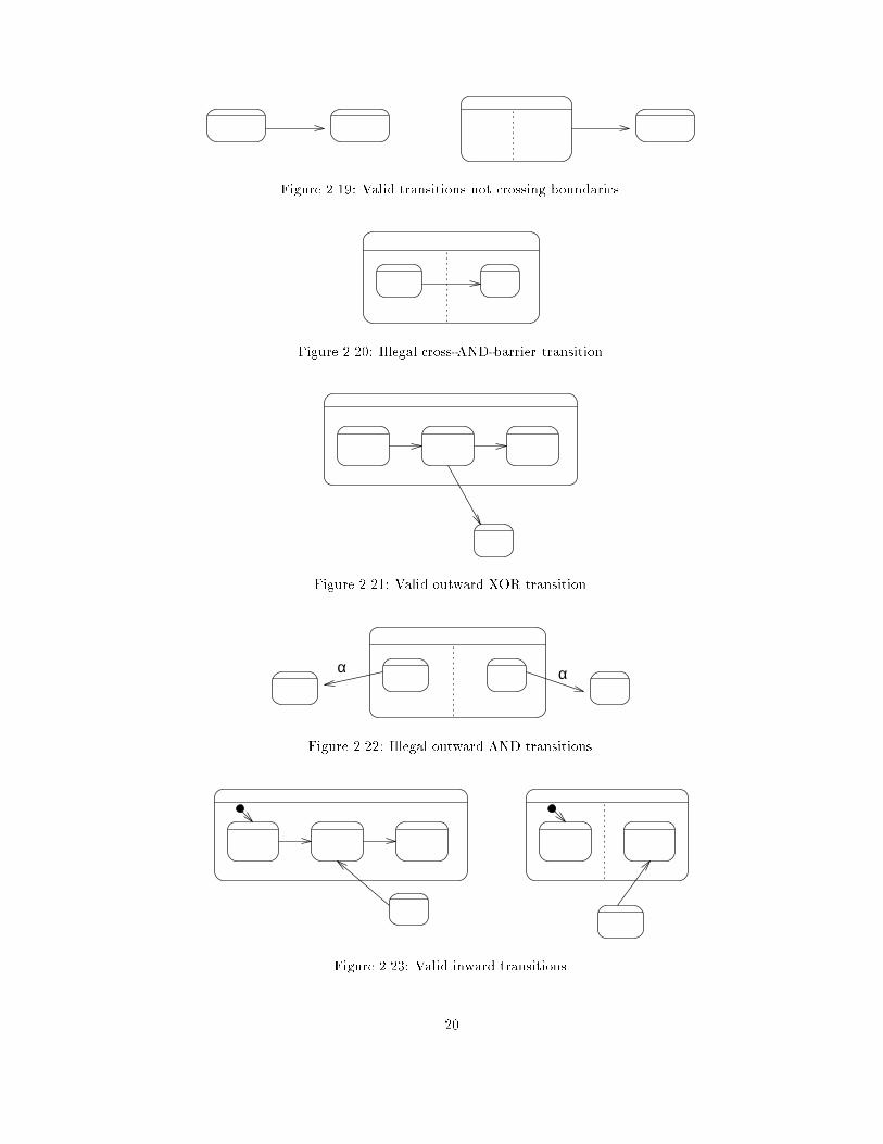
Figure 2.19: Valid transitions not crossing boundaries.
Figure 2.20: Illegal cross-AND-barrier transition.
Figure 2.21: Valid outward XOR transition.
αα
Figure 2.22: Illegal outward AND transitions.
Figure 2.23: Valid inward transitions.
20
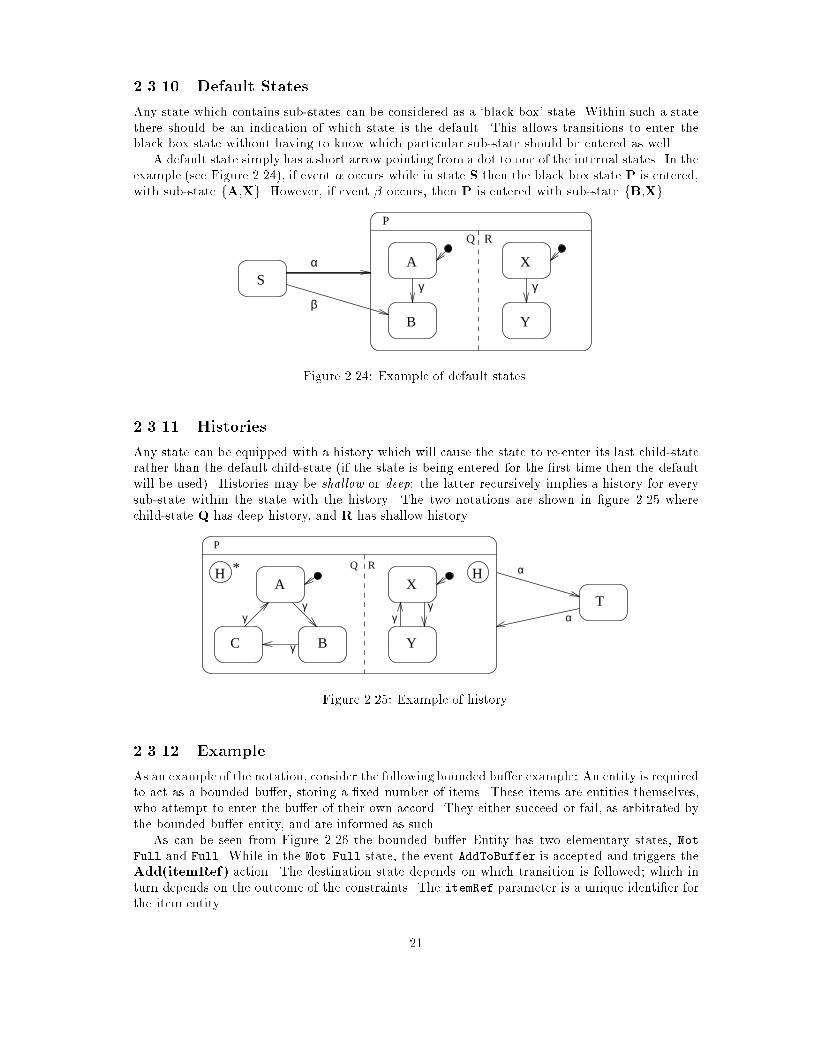
2.3.10 Default States
Any state which contains sub-states can be considered as a `black box' state. Within such a state
there should be an indication of which state is the default. This allows transitions to enter the
black box state without having to know which particular sub-state should be entered as well.
A default state simply has a short arrow pointing from a dot to one of the internal states. In the
example (see Figure 2.24), if event � occurs while in state S then the black box state P is entered,
with sub-state fA,Xg. However, if event � occurs, then P is entered with sub-state fB,Xg.
P
Q R
A
B
γ
X
γ
Y
Sα
β
Figure 2.24: Example of default states.
2.3.11 Histories
Any state can be equipped with a history which will cause the state to re-enter its last child-state
rather than the default child-state (if the state is being entered for the �rst time then the default
will be used). Histories may be shallow or deep: the latter recursively implies a history for every
sub-state within the state with the history. The two notations are shown in �gure 2.25 where
child-state Q has deep history, and R has shallow history.
H H
P
γ
γ
γ
A
BC
X
Y
γγ
Q R α
αT
*
Figure 2.25: Example of history.
2.3.12 Example
As an example of the notation, consider the following bounded bu�er example: An entity is required
to act as a bounded bu�er, storing a �xed number of items. These items are entities themselves,
who attempt to enter the bu�er of their own accord. They either succeed or fail, as arbitrated by
the bounded bu�er entity, and are informed as such.
As can be seen from Figure 2.26 the bounded bu�er Entity has two elementary states, Not
Full and Full. While in the Not Full state, the event AddToBuffer is accepted and triggers the
Add(itemRef) action. The destination state depends on which transition is followed; which in
turn depends on the outcome of the constraints. The itemRef parameter is a unique identi�er for
the item entity.
21

The Add action decrements the free attribute, and raises a SuccessAdd(itemRef) event
which reports back to the original item.
The item entity is expect to raise a RemoveFromBuffer(itemRef) event at some later time,
which has the conceptual e�ect of removing the item from the bu�er. This event is acceptable in
both states of the bounded bu�er entity, except when there are no items in the bu�er.
An simple item entity is given in Figure 2.27. The event � triggers the JoinBuffer action,
which raises the AddToBuffer event. The parameter selfRef is a standard value available to all
entities, representing a unique entity identi�er. The Wait state waits for the failure or success
noti�cation and moves on to the appropriate state. The constraints on these transitions ensure
that the item only uses events which are intended for it, as opposed to other items. Finally, event
� triggers the LeaveBu�er action, which sends the RemoveFromBuffer event to the bu�er entity.
Not Full
FullAddToBuffer(itemRef)
AddToBuffer(itemRef)[free==1] / Add(itemRef)
[free>1] / Add(itemRef)AddToBuffer(itemRef)
/ FailAdd(itemRef)
Add(itemRef) : raise SuccessAdd(itemRef);free := free -1;
FailAdd(itemRef) : raise FailedAdd(itemRef);
free := free + 1;
Actions Attributes
free : int
Remove :
RemoveFromBuffer / Remove
[free<10] / RemoveRemoveFromBuffer
Bounded-Buffer
Figure 2.26: Example of a Bounded-Bu�er entity.
2.4 Entity Editor Graphical User Interface
This section discusses the requirements of the Entity Editors' user interface by considering two
things; the objectives of a user attempting to create many entity classes for a video game, and the
style of interface provided by existing applications similar in nature to the Entity Editor.
A prototype user interface is proposed, detailing the layout of the windows, menus, and popups.
2.4.1 Requirements
At a basic level, the purpose of the Entity Editor is to allow the user to specify Entity classes.
This includes de�ning statecharts, attributes, actions, events and the inheritance structure. (See
Figure 2.28). Speci�cally, it's purpose is to specify Entity classes for use in video games and virtual
worlds.
In the course of writing even the simplest of video games, the user will probably create several
Entity classes. It would be useful to adopt the concept of a project, which references many entity
22
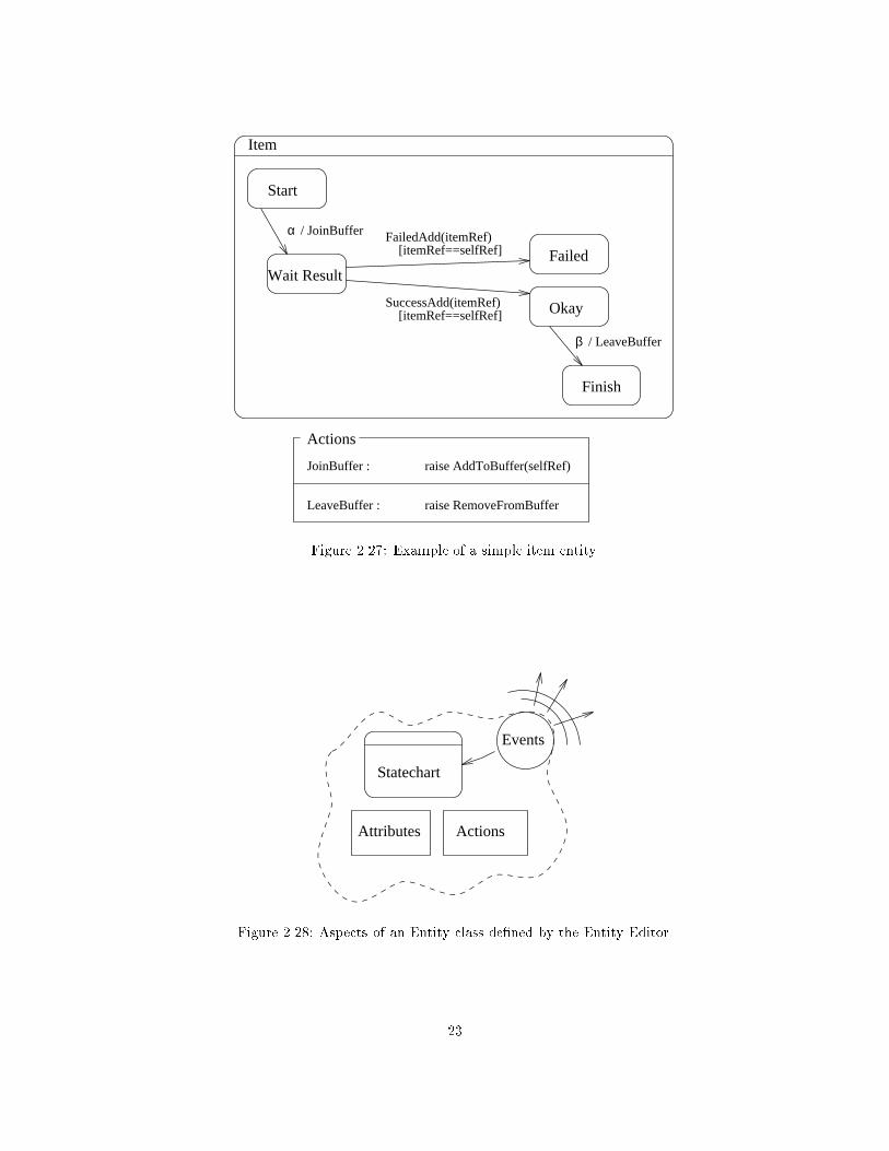
Actions
JoinBuffer : raise AddToBuffer(selfRef)
LeaveBuffer : raise RemoveFromBuffer
α / JoinBuffer
Start
Wait Result
SuccessAdd(itemRef)[itemRef==selfRef]
[itemRef==selfRef]FailedAdd(itemRef)
Okay
Failed
/ LeaveBufferβ
Finish
Item
Figure 2.27: Example of a simple item entity.
Statechart
Attributes Actions
Events
Figure 2.28: Aspects of an Entity class de�ned by the Entity Editor.
23

classes and maintains the event de�nitions used by the Entities. (See Figure 2.29). By opening
a particular project, the user has an easy way of working with that particular set of Entities and
Events. The project can have Entity classes added to it, or removed from it. One Entity class may
be referenced in many di�erent projects.
Maintaining projects could be considered ancillary to the purpose of the Entity Editor, but as
it is intended as a useful tool for creating the many entities of a video game it would be best to
consider these aspects of the tool early on in the design process.
Wall
Project: TankGame
Tank
Events:Entities: Tick
Collide
Collide
Figure 2.29: Project holding references to Entity class de�nitions.
2.4.2 Related Applications
Ideologically the Entity Editor falls somewhere between the modern day integrated compiler and
the drawing package. The project management aspects are heavily in uenced by compilers such
as THINK-C on the Macintosh, Borland C++ and MS-Visual C++ on the PC (under Windows).
The Entity speci�cation aspects are more akin to a drawing package, or visual database, as found
in ClarisWorks by Claris corp.
As far as possible, the design of the user interface to the Entity Editor has attempted to re ect
the look and feel of these (and so many other) applications. While the GUI paradigm is far from
standard, a number of common themes and ideas do exist.
Increasingly users expect certain facilities from any application that aspires to being considered
GUI driven. This fact adds considerably to the work required in designing a good user interface.
The pay back comes with the reduced training time for users of the application, as they are already
familiar with many of the basic concepts.
2.4.3 Application Window/Screen
This is the containing workplace associated with the Entity Editor. Depending on the particular
GUI, it is either an application window with menu bar (in the case of WINDOWS) or simply a new
set of menus in the common menu bar (in the case of the Macintosh). Under WINDOWs, all the
sub-windows opened by the application appear to be contained within the application window. In
contrast, the Macintosh has no concept of an application window, and simply allows any program
to place a window anywhere on the screen. The menu bar, however, changes depending on which
application is active.
24

2.4.4 Menu bar
The Entity Editor presents one commonmenu bar. While this may be duplicated for each window,
depending on the GUI, each will look the same (see �gure 2.30). The workings of the menu bar
are closely tied to the particular GUI.
Find AgainClose
SaveSave As...Revert
Quit
New
File Edit Search View Project
CutCopyPaste
Undo
GraphicalHierarchical
All transitionsNo transitionsTrans on select
New project
Close project
Remove Entity
Find...
Graph depth...
Open... Open project...
Add Entity...
Figure 2.30: Entity Editor common menu bar.
2.4.4.1 File Menu
This menu deals with the general management of Entity windows. The New, Open... and Close
options open a new (empty) Entity class window, load one from disk and close the current one,
respectively. The Save and Save As options allow the Entity to be saved to disk. Print outputs
the contents of the current window to the printer, and Quit exits the program (prompting if a
save is required).
2.4.4.2 Edit Menu
The Undo option attempts to undo the last operation. It is not always available, but can be
useful in certain situations. The Cut, Copy and Paste options act on the currently selected
graphical or text piece, and have their usual meanings. Cut removes the selection and places it in
the clipboard. Copy copies (as opposed to removes) the selection into the clipboard. Paste takes
the contents of the clipboard and copies it to the workplace.
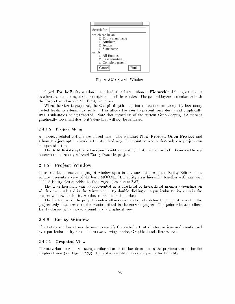
2.4.4.3 Search Menu
This provides two options: Find, which brings up a standard search window (see Figure 2.31)
allowing the user to enter the requirements of the search; and Find Again which repeats the last
search to �nd the next match.
The search facility allows the user to �nd particular Entity classes, or particular Actions or
Attributes of a class. When a particular Entity window is active, then the search is automatically
limited to that window (unless All Entities is checked). When the Project window is active, the
search covers all the entities.
2.4.4.4 View Menu
The �rst two options a�ect either the Project window or the current Entity window, depending
on which is active. Graphical changes the current window so that it displays a graphical rep-
resentation of it's contents. In the case of the Project window, a horizontal class hierarchy is
25
Search for :
which can be anEntity class nameAttributeActionState name
SearchAll EntitiesCase sensitiveComplete match
Cancel Find
Figure 2.31: Search Window.
displayed. For the Entity window a standard statechart is shown. Hierarchical changes the view
to a hierarchical listing of the principle items of the window. The general layout is similar for both
the Project window and the Entity windows.
When the view is graphical, the Graph depth... option allows the user to specify how many
nested levels to attempt to render. This allows the user to prevent very deep (and graphically
small) sub-states being rendered. Note that regardless of the current Graph depth, if a state is
graphically too small due to it's depth, it will not be rendered.
2.4.4.5 Project Menu
All project related options are placed here. The standard New Project, Open Project and
Close Project options work in the standard way. One point to note is that only one project can
be open at a time.
The Add Entity option allows you to add an existing entity to the project. Remove Entity
removes the currently selected Entity from the project.
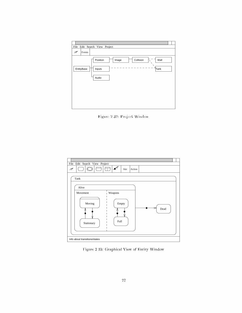
2.4.5 Project Window
There can be at most one project window open in any one instance of the Entity Editor. This
window presents a view of the basic MOONLIGHT entity class hierarchy together with any user
de�ned Entity classes added to the project (see Figure 2.32).
The class hierarchy can be represented in a graphical or hierarchical manner depending on
which view is selected in the View menu. By double clicking on a particular Entity class in the
project window, an Entity window is opened on that class.
The button bar of the project window allows new events to be de�ned. The entities within the
project only have access to the events de�ned in the current project. The pointer button allows
Entity classes to be moved around in the graphical view.
2.4.6 Entity Window
The Entity window allows the user to specify the statechart, attributes, actions and events used
by a particular entity class. It has two viewing modes, Graphical and Hierarchical.
2.4.6.1 Graphical View
The statechart is rendered using similar notation to that described in the previous section for the
graphical view (see Figure 2.33). The notational di�erences are purely for legibility.
26
File Edit Search View Project
Events
EntityBase Inputs
Position
Audio
Image Collision
Tank
Wall
Figure 2.32: Project Window.
Moving
Stationary
File Edit Search View Project
ActionAttr
Tank
Alive
Dead
Movement
Empty
Full
Weapons
Info about transitions/states
Figure 2.33: Graphical View of Entity Window.
27

File Edit Search View Project
Dead
Alive
Movement
Moving
Forward
Backward
Stationary
Weapons
Empty
Not Empty
Tank
Attr Action
Figure 2.34: Hierarchical View of Entity Window.
XOR and AND states may not have their sub-states rendered. As signi�cant depth in a
statechart may cause the sub-states to appear very small, some XOR and AND states may be
rendered in an abreviated way. Instead of the name appearing in the title bar and the sub-states
appearing below the bar, the title bar is empty and the name appears below it. Two factors a�ect
whether or not a state will be abbreviated; the current Graph depth, and the visible size of the
rendered state.
For example, the Moving state in �gure 2.33 is actually an XOR state with two sub-states.
However, they would be too small to see, so the abreviated form is used.
Also for legibility reasons, transition annotations are not placed on the statechart diagram.
Instead, they are displayed in the information panel at the bottom of the window when the pointer
is over a particular transition.
The graphical view is used to create the statechart. The button bar at the top of the window
has a number of icons which are used to add new states and transitions to the statechart. In
addition, the states may me moved around, resized and edited.
The outermost visible with the graphical view may not be the outermost state of the whole
statechart. By double clicking on the title of the outermost visible state, the view is redrawn with
the parent state of that state as the outermost visible. Similarly, if a sub-state is double clicked
on, it becomes the outermost visible state.
The main drawback with the graphical view is the limit as to how much information can be
legibily displayed.
2.4.6.2 Hierarchical View
All statechart sub-states are shown concisely in the hierarchical view. However, no transitions are
show. The states are displayed in a vertical list with sub-states placed under their parent state and
indented slightly. In the case of an XOR state, a single vertical line joins the sub-states to their
parent state. For AND states, two parallel lines are used (See Figure 2.34). By double clicking on
any state name, the view changes to the graphical view, with that state as the outermost visible.
With the hierarchical view it is possible to see that the Moving state is an XOR state made
up of two sub-states, Forward and Backward.
28
2.4.6.3 Button Bar
The button bar provides the tools to allow new states to be added to the statechart. Note that
most of the facilities are only available while in the graphical view. There is a button to:
� change the pointer to the default mode of operation. That is, to drag and resize existing
states;
� add a new elementary state to the statechart;
� add a new unstable state;
� add a new XOR state;
� add a new AND state;
� add a new transition;
� add an attribute to the Entity class;
� add an action to the Entity class.
The button for adding a new transition requires that the user specify the source and destination
states. When this is done, a popup window opens which asks them to enter details of the event,
constraint and action. The Attribute and Action buttons open pop up windows which allow details
of Attributes and Actions to be added to the Entity class.
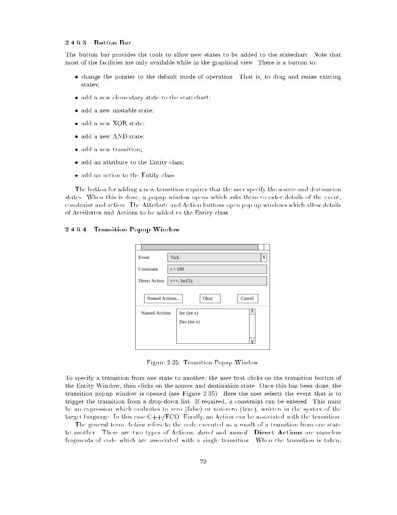
2.4.6.4 Transition Popup Window
Event
Constraint
Direct Action
CancelNamed Actions... Okay
Inc (int x)
Dec (int x)
Named Actions
Tick
t < 100
c++; Inc(5);
Figure 2.35: Transition Popup Window.
To specify a transition from one state to another, the user �rst clicks on the transition button of
the Entity Window, then clicks on the source and destination state. Once this has been done, the
transition popup window is opened (see Figure 2.35). Here the user selects the event that is to
trigger the transition from a drop-down list. If required, a constraint can be entered. This must
be an expression which evaluates to zero (false) or non-zero (true), written in the syntax of the
target language. In this case C++/ECO. Finally, an Action can be associated with the transition.
The general term Action refers to the code executed as a result of a transition from one state
to another. There are two types of Actions, direct and named. Direct Actions are nameless
fragments of code which are associated with a single transition. When the transition is taken,
29

the code fragment is executed. There is no way to associate the same code fragment with a
di�erent transition (other than using cut and paste), as it is implemented as in-line code in the
state machine.
However, there may be sets of instructions that the user wishes to invoke from many di�erent
transitions. In this case, named Actions can be de�ned (see below), which contain the frequently
used code. Many transitions can then invoke the one named Action by calling it from within their
direct actions. A named Action is implemented as a single method. The invocation of a named
Action is actually a method invocation.
The popup initially opens without displaying the current list of named Actions. If the Named
Actions button is clicked on, the window expands to show the list. This can be a useful reminder
list for the user when they are invoking a named Action from the direct Action.
2.4.6.5 Attributes Popup Window
AddRemove
int t;
char c;
<New>
int t;
Figure 2.36: Attributes Popup Window.
The attributes popup window (see Figure 2.36) is opened by clicking on the Attrs button in the
Entity window. From here, new attributes can be declared and existing ones edited or deleted.
The declaration must be in the syntax of the target language, so in this case attributes are declared
in the same way as variables in C++/ECO.
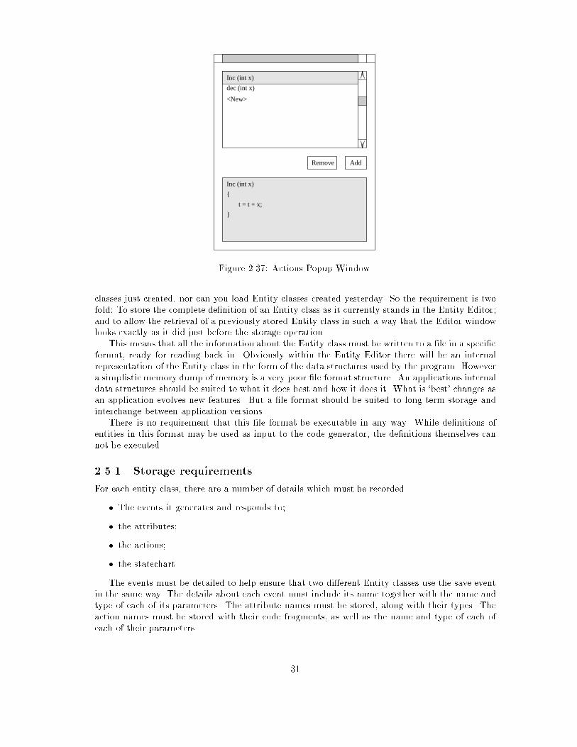
2.4.6.6 Named Actions Popup Window
The actions popup window (see Figure 2.37) is opened by clicking on the Actions button in the
Entity window. From here, new named Actions can be declared and existing ones edited or deleted.
As discussed previously, the actions must written in the syntax of the target language. In this case,
C++/ECO.
2.4.7 Summary
The Graphical User Interface presented by the Entity Editor must strive for simplicity and elegance.
It must present the statechart clearly, and make it easy for the user to alter it. As the user is
required to enter small fragments of code, aids should be provided to make this as simple as
possible. It must also be possible to manage several Entity classes in the one project, and allow
common de�nitions of events to pass between them.
2.5 Entity De�nition File Format
From a logistic point of view, the most fundamental operations that the Entity Editor must perform
are those of storing and retrieving Entity classes. Without these abilities, you can not save Entity
30
AddRemove
<New>
Inc (int x)
{
t = t + x;
}
Inc (int x)
dec (int x)
Figure 2.37: Actions Popup Window.
classes just created, nor can you load Entity classes created yesterday. So the requirement is two
fold: To store the complete de�nition of an Entity class as it currently stands in the Entity Editor;
and to allow the retrieval of a previously stored Entity class in such a way that the Editor window
looks exactly as it did just before the storage operation.
This means that all the information about the Entity class must be written to a �le in a speci�c
format, ready for reading back in. Obviously within the Entity Editor there will be an internal
representation of the Entity class in the form of the data structures used by the program. However
a simplistic memory dump of memory is a very poor �le format structure. An applications internal
data structures should be suited to what it does best and how it does it. What is `best' changes as
an application evolves new features. But a �le format should be suited to long term storage and
interchange between application versions.
There is no requirement that this �le format be executable in any way. While de�nitions of
entities in this format may be used as input to the code generator, the de�nitions themselves can
not be executed.
2.5.1 Storage requirements
For each entity class, there are a number of details which must be recorded.
� The events it generates and responds to;
� the attributes;
� the actions;
� the statechart.
The events must be detailed to help ensure that two di�erent Entity classes use the save event
in the same way. The details about each event must include its name together with the name and
type of each of its parameters. The attribute names must be stored, along with their types. The
action names must be stored with their code fragments, as well as the name and type of each of
each of their parameters.
31
Finally, the hierarchical statechart must stored, together with the current graphical location
and size of each state. This graphical information is super uous in the context of the execution
of the state machine. However, it is essential from the point of view of the user who wishes to
arrange their statecharts in a visually convenient way.
2.5.2 File Format Philosophy
Before designing a �le format to hold the details identi�ed above, we must consider that in future
versions some of these details may change, or new ones might emerge. So the storage format must
be versatile enough to allow for future expansion.
For this reason a grammar based structure is proposed for the storage format, using standard
ASCII characters to encode the tokens. This provides two major bene�ts. Firstly, the resulting
Entity de�nitions are ASCII readable, allowing easy human examination. Secondly, a grammar
can be expanded to include new language constructs by ensuring that the language the grammar
describes is a superset of the old language. New versions of the Entity Editor should always be
able to read old Entity �les, as they will always be in a language that is just a subset of the later
versions of the language.
This approach is not uncommon. Consider Adobe's PostScript or Microsofts RTF (Rich Text
Format). Both are grammar based, ASCII encoded interchange formats.
2.5.3 Format Syntax
The general syntax is not unlike a typical programming language, such as C or Pascal. The overall
order of declarations is: events; attributes; actions; and �nally a single state de�nition which
contains all the states of the Entity as sub-states.
The declaration of an event includes the events name (a standard alphanumeric identi�er) and
its parameters. For example
event Time (msecs : int);
declares an event called `Time'which has one integer parameter, the current system time in millisec-
onds. This event might be raised by a clock entity every few milliseonds, and might be subscribed
to by entities interested in knowing the current time.
A typical Entity class would have many event declarations. No distinction is drawn between
those events that are generated and those that are received. These declarations simply allowing
the Entity Editor to perform basic type checking on the use of the events.
The attributes are declared as small code fragments which declare the appropriate variable.
Consider
attribute [[int xposition;]]
attribute [[int yposition;]]
which declares two attributes of type integer.
Named Actions are de�ned by providing the action name; its parameters; and the associated
code fragment. For the moment, this code fragment must be in the target language, C++/ECO.
Ideally this would be a generic language, which could be converted into the particular syntax of
the underlying language. This would have to be the case if the Entity Editor were to be completely
language independent. In the following example everything between the [[ and ]] will be pasted
into the resulting Entity code.
action [[
IncEnergy (int stamina, int food) {
energy = energy + stamina;
stomach = stomach + food;
32

}
]]
Within the code fragment the user can do anything that can be done from within a typical
C++/ECO program. However, it would be wise to limit individual actions to perform only simple
modi�cations to the attributes, or invocations of inherited methods.
The state of the Entity must be contained in a single enclosing state, typically an XOR or
AND state. Within a state there can be several sub-states. The current syntax supports XOR
states, AND states and elementary states. The hierarchical nature of statecharts is conveniently
represented by the nesting of state statements. Consider the following example (see Figure 2.38).
Example
YX
D
Tick
H
A
q[n>0] p/Increase
B C
E
Figure 2.38: Example Statechart for encoding.
xorstate ``Example'' (left=0,right=300,top=0,bottom=200)
{
andstate ``X'' (left=0,right=150,top=10,bottom=190)
{
shallowhistory;
state ``A'' (left=60,right=80,top=10,bottom=30);
state ``B'' (left=60,right=80,top=90,bottom=110);
trans ``A'' to ``B'' (curve=1) on p do Increase;
trans ``B'' to ``A'' (curve=1) on q when (num>0);
default ``A'' (x=55,y=15);
}
andstate ``Y'' (left=150,right=300,top=10,bottom=190)
{
state ``C'' (left=30,right=50,top=80,bottom=100);
xorstate ``D'' (left=....)
{
state ``E'' (left=...);
}
trans ``C'' to ``D''.''E'' (curve=1) on Tick;
default ``C'' (x=...);
}
}
The bracketed expressions after the state names are properties of the state, and are used to
store the graphical information about the state. This information would be used by the Entitor to
recreate the same looking statechart. Similar properties are included for the transitions. In this
33

example curve dictates what type of curve should be used to draw the transition line. (curve=1
signi�es a straight line).
2.5.4 Grammar
The following represents a basic grammar for the Entity File Format. The syntax used de�nes
multiple productions from the one non-terminal symbol. If the modi�er `opt' is placed after a
non-terminal it means that it is optional. De�nitions for elementary non-terminals are not given.
<DECLARS>
-> <DECLAR>
-> <DECLAR> <DECLARS>
->
<DECLAR>
-> event <IDENT> <PARAMDECLS>opt ;
-> attribute <IDENT> : <TYPE> ;
-> action <IDENT> <PARAMDECLS>opt <FRAGMENT>
-> <STATEDECL>
<STATEDECL>
-> xorstate <STNAME> <PROPTYS>opt { <SUBS> }
-> andstate <STNAME> <PROPTYS>opt { <SUBS> }
-> state <STNAME> <PROPTYS>opt ;
<SUBS>
-> <SUB>
-> <SUBS> <SUB>
<SUB>
-> <STATEDECL>
-> deephistory;
-> shallowhistory;
-> default <STNAME> <PROPTYS>opt ;
-> trans <DEEPSTNAME> to <DEEPSTNAME> <PROPTYS>opt <TRANSDECL> ;
<TRANSDECL>
-> <TREVENT>opt <TRCONST>opt <TRACTION>opt
<TREVENT>
-> on <IDENT>
<TRCONST>
-> when <FRAGMENT>
<TRACTION>
-> do <FRAGMENT>
<PASSPARAMS>
-> ( <PASSPLIST> )
<PASSPLIST>
34
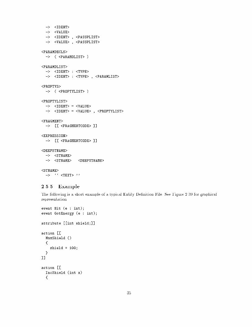
-> <IDENT>
-> <VALUE>
-> <IDENT> , <PASSPLIST>
-> <VALUE> , <PASSPLIST>
<PARAMDECLS>
-> ( <PARAMDLIST> )
<PARAMDLIST>
-> <IDENT> : <TYPE>
-> <IDENT> : <TYPE> , <PARAMLIST>
<PROPTYS>
-> ( <PROPTYLIST> )
<PROPTYLIST>
-> <IDENT> = <VALUE>
-> <IDENT> = <VALUE> , <PROPTYLIST>
<FRAGMENT>
-> [[ <FRAGMENTCODE> ]]
<EXPRESSION>
-> [[ <FRAGMENTCODE> ]]
<DEEPSTNAME>
-> <STNAME>
-> <STNAME> . <DEEPSTNAME>
<STNAME>
-> `` <TEXT> ''
2.5.5 Example
The following is a short example of a typical Entity De�nition File. See Figure 2.39 for graphical
representation.
event Hit (e : int);
event GotEnergy (e : int);
attribute [[int shield;]]
action [[
MaxShield ()
{
shield = 100;
}
]]
action [[
IncShield (int x)
{
35

Tank
Full Shield
Partial Shield
Hit(e)/DecShield(e)
GotEnergy(e)[shield+e<100]/IncShield(e)
/MaxShield
Hit(e)/DecShield(e)
Alive
Dead
/ExplodeHit(e)[shield-e<0]
Actions
DecShield (e : int) shield = shield - e;
IncShield (e : int) shield = shield + e;
MaxShield shield = 100;
Explode (Change graphics)
Attributes
shield : int
GotEnergy(e)[shield+e>=100]
Figure 2.39: Example of a simple Tank statechart.
shield = shield + x;
}
]]
action [[
DecShield (int x)
{
shield = shield - x;
}
]]
action [[
Explode
{
//perform some graphical changes
}
]]
xorstate ``Tank'' (left=0,right=300,top=0,bottom=200)
{
xorstate ``Alive'' (left=...)
{
state ``Full Shield'' (left=...);
state ``Partial Shield'' (left=...);
trans ``Full Shield'' to ``Partial Shield'' (curve=1)
on Hit do [[DecShield(e);]]
trans ``Partial Shield'' to ``Full Shield'' (curve=1)
36

on GotEnergy when [[(shield+e>=100)]] do [[MaxShield();]]
trans ``Partial Shield'' to ``Partial Shield'' (curve=2)
on Hit do [[DecShield(e);]]
trans ``Partial Shield'' to ``Partial Shield'' (curve=2)
on GotEnergy when [[(shield+e<100)]] do [[IncShield(e);]]
default ``Full Shield'';
}
state ``Dead'' (left...);
trans ``Alive'' to ``Dead'' (curve=1)
on Hit when [[(shield-e<0)]] do [[Explode ();]]
}
2.6 Entity Editor Code Generator
This section considers how Entity classes should be represented in C++/ECO. The Entity Editor
should be able to output source code in C++/ECO which can be compiled, linked and executed
within the VOID execution environment. This source code is a C++/ECO representation of the
statechart, actions and attributes of the Entity
The general problem is two-fold. Firstly, code which executes as a state machine modelling the
Entity statechart must be generated. Secondly, any code fragments (actions, constraints etc) must
be translated into the target source language.
While it would be ideal to make the Entity Editor language independent, the immediate solution
is to produce code only for C++/ECO. If the user is required to enter all code fragments in the
chosen target language, then no code translation need occur. However, the problem of generating
the state machine still remains.
2.6.1 Starting Point
GUIFront-end
DefinitionEntity
File
CodeGenerator C++/ECO
Entity DefinitionGenerator
Figure 2.40: General structure of the Entity Editor.
From Figure 2.40 it can be seen that the Code Generator is considered to be a separate program.
The fundamental point is that the Code Generator takes as input the Entity De�nition File, and
outputs a representation of the Entity in the target language. The other alternative to code
generation would be to allow the generator have access to the internal structures of the Entity
Editor, and produce the target language code from there. This would probably mean making the
code generator part of the Entity Editor program.
37

Based on the philosophy that a programs internal data structures should be designed around
the requirements of that program, it would appear that two separate data representations are
required. One for the graphical manipulation of the statechart in the Entity Editor; and one
for translation purposes in the Code Generator. While it may be possible to resolve these two
structures into one, keeping them separate simpli�es their design. In addition it may simplify the
design and implementation of the two programs; the Entity Editor and the Code Generator.
Given that we have a standard Entity File Format, we need to build a single interchange layer to
convert from the �le format to the Code Generator's internal representation. This is the principle
cost involved in having a separate Code Generator. Considering the clean division of problem
provided by this design approach, it is an acceptable cost. So the decision is to have the Code
Generator as a separate program from the main of the Entity Editor.
2.6.2 No Reverse Engineering
One noticeable omission from the design is that it is not possible to convert C++/ECO code to
the Entity De�nition File format. The general problem of converting an arbitrary C++/ECO
program to statechart form is simply too complex. Even the simpli�ed problem of taking code
initially produced by the code generator, but subsequently altered slightly, and mapping it back
to a statechart is very complex.
If small changes need to be made to the code produced by the Entity Editor, they should be
made at the level of the Entity Editor instead. This is quite easy if the change is to an action. If
the change is to the state machine then the correct approach would be to identify the changes at a
statechart level, and not by making almost arbitrary changes to relatively complex code generated
automatically.
2.6.3 Basic Statechart to Code Mapping
The problem to solve is the automatic generation of a state machine that simulates the Entity's
statechart. This section outline a C++/ECO speci�c solution, which deals with simple statecharts.
Complexities, such as orthogonality, are dealt with in more detail later.
2.6.3.1 Direct Mappings
Assumptions made about the target language (C++/ECO) mean that many concepts present at
the Entity level can be mapped directly to the target language level.
� An Entity class maps to a single C++/ECO class.
� An Attribute of an Entity classes maps to a single data member of a C++/ECO class.
� The Events exchanged between Entities are mapped directly to the events supported by
C++/ECO.
� The ability of an Entity to raise an event is directly mapped to the raising of an event in
C++/ECO.
� The FIFO queueing of events is provided by C++/ECO.
� Named Actions are mapped to methods of the C++/ECO class.
� Direct Actions are mapped to code fragments of C++/ECO.
� The constraints on transitions in the Entity statechart are mapped directly to conditional
expressions of C++/ECO.
38
2.6.3.2 Event Handling
The processing of event noti�cations at the Entity level is quite di�erent than at the C++/ECO
level. In the former case, an event potentially triggers constraint evaluations and state transitions,
each possibly executing an action. In the latter, an event triggers the evaluation of a number of
pre-conditions, each of which may trigger a method - no state is maintained.
To achieve a mapping between the two, the C++/ECO methods must perform the Entity
constraint evaluation, update the state variables and execute the appropriate actions.
Event subscription and unsubscription are considered heavy-weight operations, so they cannot
be done on every state transition. So to avoid the overhead of unsubscribing and resubscribing
to events as the state of an Entity changes, an Entity simply subscribes to all the events it will
every require when it is created, and unsubscribes from them when it is destroyed. This means
that while an Entity may be in a particular state waiting for one particular event, the underlying
C++/ECO object may remain subscribed to many more events. 1
The facilities provided by C++/ECO allow an event to invoke a number of preconditions, each
of which can invoke a �xed method. The precondition facility is used as a �lter to determine if the
event that arrived is currently accepted by the state machine. If it's in a state that has a transition
that depends on the arrival of that event, then the precondition succeeds and triggers the method.
The method in question is written speci�cally to handle that particular event. It is referred to
as an event-handler method. There is one such method for each event of interest to the Entity.
Conceptually, it is responsible for determining what state the entity is in, and as a result, what
needs to be done. The apparent concurrency provided by the AND states is simulated here. If the
event-handler �nds that the state machine is in an AND state, then it must cater for the two
active states.
The event-handler method actually delegates the work to one or more depart-on methods.
These are methods which responsible for departing from a particular state on the arrival of a
particular event. For each set of transitions in a statechart that leave the same state and are
triggered by the same event there is a unique depart-on method. When these methods are
executed, they assume the state machine is in a particular state and that a certain event has
occurred. They are responsible for determining which of the transitions is to be taken, executing
the chosen transitions action, and putting the state machine in a new state.
In most cases the depart-on method will only have to deal with one transition. However, if
a state has many transitions leaving it by the same event, then the depart-on method will have
to evaluate the constraints of each transition until it �nds one that can be taken. Note that the
�rst transition evaluated with a valid constraint will be taken. (This is in keeping with comments
made about non-determinism in statecharts.)
2.6.3.3 State Maintenance
As mentioned above, conceptually, the event-handler methods are responsible for determining
what state the state machine is currently in. However, as the last transition will have placed the
state machine in some known state, it would be wasteful for the event-handler to perform any
kind of switch operation. Instead, when a transition places the state machine in some new state,
what actually occurs is that changes are made to a table of depart-on method references.
At any given time, this table determines the current state, as it de�nes what depart-on
methods must be invoked by each of the event-handlers. The table is actually a number of lists.
For each event-handler there is a list of depart-on method references that must be invoked
when the event-handler runs.
When an event arrives, it �rst triggers a particular precondition. This examines the list of
depart-on references for that event, and only triggers the associated event-handler if it is not
1User level support may be provided by the Entity Editor to allow the user to suggest to the Code Generatorthat dynamic subscription and unsubscription would be more optimal in particular situations.
39

empty. If it is empty, then the state machine is simply not in a state that requires that event, and
it is discarded. (This is consistent with the view that a statechart only accepts sequences of events
that match it's `event language'.)
When invoked, the event-handler invokes each of methods speci�ed in the appropriatedepart-
on method list. Precautions are taken to ensure that the �rst depart-on method does not over-
write the list before it is fully used. The list of depart-on methods is sorted by their depth order.
Those entries departing from outermost states are dealt with �rst. This is to ensure that apparent
non-determinism is solved by only taking the outermost transition. If the outermost is not taken
because it's constraint fails, then the inner ones have a chance to execute.
2.6.3.4 Scope in Actions and Constraints
The fragments of code that the user enters as the Actions or Constraints is used verbatim in the
mapping from statecharts to C++/ECO. While the user may potentially enter anything at all,
some consideration should be given to what is sensible for them to access. 2
For a constraint the user should enter a typical C++/ECO expression which will evaluate to
either true (non-zero) or false (zero). The variables that should be considered in-scope are the
event parameters and the attributes of the Entity. Access to the state of the Entity is provided
through special functions.
Direct Actions are simply a number of C++/ECO statements that the user associates with a
particular transition. They have no identifying name, so cannot be accessed by other transitions.
As with constraints, the variables that should be considered in scope are the Attributes and event
parameters. Queries about the current state can be made through special functions.
Named actions are ordinary C++/ECO methods. They can have local variables, and can access
the attributes of the Entity as well as the values of their own parameters. However, in contrast
to constraints and direct actions they cannot access the parameters of the event that ultimately
triggered their invocation. Note that in practise every transition that performs some action has
a direct Action associated with it. Transitions that appear to invoke a named Action do so via a
single statement direct action which invokes the named Action.
2.6.4 Simple Example
CB
A
p/Inc( ) p/Inc( )
p/Inc( )
Example
q[x>3]/x--
Figure 2.41: A Simple Statechart.
To demonstrate the general format of the code produced by applying the mechanisms described
above, consider the following example. A typical graphical representation of the Entity class is
given in �gure 2.41. The statechart has three elementary states, each of which responds to event
p by invoking the named Action Inc and moving along the cycle. State A also responds to event q
2Obviously the potential for user error is signi�cant, and in subsequentversions of the tool, code-creating facilitiesmay need to be provided to help the user write correct code.
40
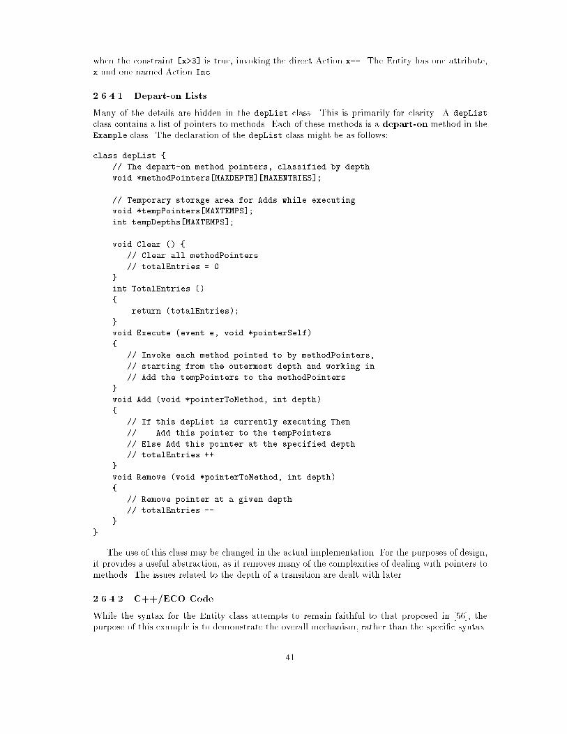
when the constraint [x>3] is true, invoking the direct Action x--. The Entity has one attribute,
x and one named Action Inc.
2.6.4.1 Depart-on Lists
Many of the details are hidden in the depList class. This is primarily for clarity. A depList
class contains a list of pointers to methods. Each of these methods is a depart-on method in the
Example class. The declaration of the depList class might be as follows:
class depList {
// The depart-on method pointers, classified by depth
void *methodPointers[MAXDEPTH][MAXENTRIES];
// Temporary storage area for Adds while executing.
void *tempPointers[MAXTEMPS];
int tempDepths[MAXTEMPS];
void Clear () {
// Clear all methodPointers
// totalEntries = 0
}
int TotalEntries ()
{
return (totalEntries);
}
void Execute (event e, void *pointerSelf)
{
// Invoke each method pointed to by methodPointers,
// starting from the outermost depth and working in.
// Add the tempPointers to the methodPointers.
}
void Add (void *pointerToMethod, int depth)
{
// If this depList is currently executing Then
// Add this pointer to the tempPointers
// Else Add this pointer at the specified depth
// totalEntries ++
}
void Remove (void *pointerToMethod, int depth)
{
// Remove pointer at a given depth
// totalEntries --
}
}
The use of this class may be changed in the actual implementation. For the purposes of design,
it provides a useful abstraction, as it removes many of the complexities of dealing with pointers to
methods. The issues related to the depth of a transition are dealt with later.
2.6.4.2 C++/ECO Code
While the syntax for the Entity class attempts to remain faithful to that proposed in [56], the
purpose of this example is to demonstrate the overall mechanism, rather than the speci�c syntax.
41

class Example {
int x; // Attributes
Inc () { x++ } // Actions
depList pDepList; // Depart-on lists
depList qDepList;
inevents pEevent, qEvent; // Declare events.
// Preconditions
constraint pPrecond {
if (pDepList.totalEntries() == 0) discard;
else process-passive;
}
constraint qPrecond {
if (pDepList.Empty ()) discard;
else process-passive;
}
// Event handlers
pHandler (event e) { pDepList.Execute (e, self); }
qHandler (event e) { qDepList.Execute (e, self); }
// Register for events
pHandler handles (pEvent, NULL, pPrecond, NULL);
qHandler handles (qEvent, NULL, qPrecond, NULL);
// Constructor
Example () {
pDepList.Clear ();
qDepList.Clear ();
// Setup initial state
pDepList.Add (&dep_A_On_p, 1);
qDepList.Add (&dep_A_on_q, 1);
}
// Methods for Departing from <state> on event <event>
dep_A_on_p (event e) {
Inc (); // The action
qDepList.Remove (&dep_A_on_p, 1);
pDepList.Remove (&dep_A_on_q, 1);
pDepList.Add (&dep_B_on_p, 1);
return (1);
}
dep_B_on_p (event e) {
Inc (); // The action
pDepList.Remove (&dep_B_on_p, 1);
pDepList.Add (&dep_C_on_p, 1);
return (1);
}
42

dep_C_on_p (event e) {
Inc (); // The action
pDepList.Remove (&dep_C_on_p, 1);
pDepList.Add (&dep_A_on_p, 1);
qDepList.Add (&dep_A_on_q, 1);
return (1);
}
dep_A_on_q (event e) {
if (x > 3) { // constraint
x--; // The action
pDepList.Remove (&dep_A_on_q, 1);
qDepList.Remove (&dep_A_on_p, 1);
pDepList.Add (&dep_C_on_p,1);
return (1);
}
return (0);
}
}
Note that each depart-on method returns one or zero, depending on whether the transition
was actually taken or not. This is so that depList.Execute() can determine whether transitions
that are deeper should be given a change to execute. 3
2.6.5 Depth
A
X
Y
q
pr
q
rBC
Figure 2.42: Statechart illustrating depth.
Consider the statechart in �gure 2.42. Transitions which originate from a compound state (such
as the transition from Y to Z) introduce the complication of recursively exiting from that state.
Examine the depart-on methods in the last example. A general form for such a method might
be:
If (constraint is true) Then
Perform some action.
Exit from the source state of the transition
(ie Remove depart-on methods of source state.)
Enter the destination state of the transition.
(ie Add depart-on methods of destination state.)
3This means there is actually a dependency between the action code and the state machine code. The state ma-
chine code has, in e�ect, read access requirements on the attributes. If the actions are considered as sequential codeand the state machine as synchronisation code, then it is impossible to separate the sequential and synchronisationcode. In such a situation it is not desirable to have internal concurrency within an object, as deadlock may occur(readers/writers problem). See [44].
43

Return (1)
EndIf
Return (0)
In the case of an elementary state, the exiting is achieved by simply removing the depart-on
methods of the current state from the various DepLists. However, in Figure 2.42 the transition from
Y to Z must exit from an XOR state. The dep Y on r method must actually call a special method
exit Y. This identi�es which sub-state is active (A or B) and removes the appropriate depart-on
methods. As the sub-states could be compound states (XOR or AND) the exitmethods may need
to call other exit methods.
For each AND and XOR state there is a single exit method, which is responsible for removing
the depart-onmethods from the DepLists of itself, and all it's sub-states. To achieve this, special
state-variablesmust be maintained. In the example, there would be a Ystatevar variable which
could hold the value A STATE or B STATE. Before an exit function terminates, it either resets these
variables to default values, or leaves them as they are. This provides the defaulting and history
abilities of the statechart. 4
Similarly, for each compound state there is a single enter function, with responsibility for
recursively adding the appropriate depart-onmethods to the DepLists. This is done on the basis
of the current values of the state-variables. In the case of the transition from Z to Y, theDepart-
on method simply calls enter Y. In the case of the transition from Z to B, the Depart-onmethod
must �rst set the value of Y's state-variable to B, and then call enter Y.
With reference again to Figure 2.42, the enclosing state, X, is considered to be at a depth of 0.
The sub-states of this state (Y and Z) are at depth 1. Similarly, the sub-states of Y are at depth
2, and so on. The depart-on methods would be as follows.
dep_Y_on_r (event e)
{
exit_Y (); // Remove all X depart-ons
Xstatevar = Z_STATE;
rDepList.Add (&dep_Z_on_r, 1);
rDepList.Add (&dep_Z_on_q, 1);
return (1);
}
dep_Z_on_r (event e)
{
rDepList.Remove (&dep_Z_on_r, 1);
rDepList.Remove (&dep_Z_on_q, 1);
XStatevar = Y_STATE;
enter_Y ();
return (1);
}
dep_Z_on_q (event e)
{
rDepList.Remove (&dep_Z_on_r, 1);
rDepList.Remove (&dep_Z_on_q, 1);
XStatevar = Y_STATE;
YStatevar = B_STATE;
enter_Y ();
return (1);
}
4The di�erence between shallow and deep histories does not arise at this level. Each XOR or AND state eitherhas history, or uses defaults. Deep history simply means that all sub-states have histories.
44
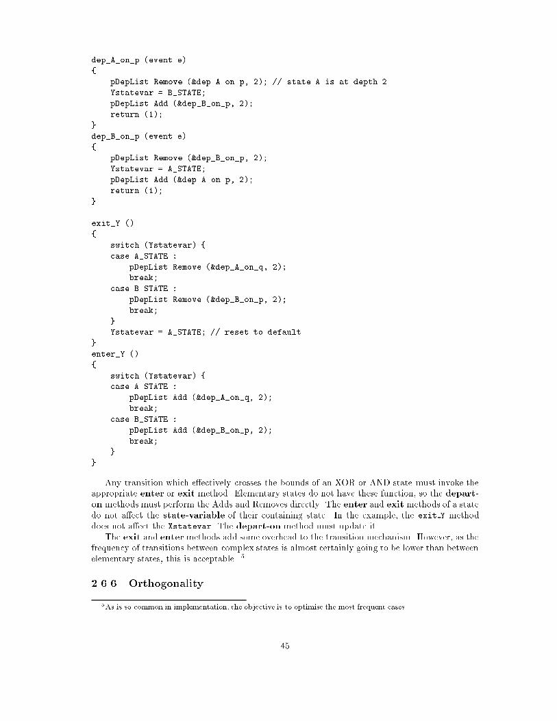
dep_A_on_p (event e)
{
pDepList.Remove (&dep_A_on_p, 2); // state A is at depth 2
Ystatevar = B_STATE;
pDepList.Add (&dep_B_on_p, 2);
return (1);
}
dep_B_on_p (event e)
{
pDepList.Remove (&dep_B_on_p, 2);
Ystatevar = A_STATE;
pDepList.Add (&dep_A_on_p, 2);
return (1);
}
exit_Y ()
{
switch (Ystatevar) {
case A_STATE :
pDepList.Remove (&dep_A_on_q, 2);
break;
case B_STATE :
pDepList.Remove (&dep_B_on_p, 2);
break;
}
Ystatevar = A_STATE; // reset to default
}
enter_Y ()
{
switch (Ystatevar) {
case A_STATE :
pDepList.Add (&dep_A_on_q, 2);
break;
case B_STATE :
pDepList.Add (&dep_B_on_p, 2);
break;
}
}
Any transition which e�ectively crosses the bounds of an XOR or AND state must invoke the
appropriate enter or exit method. Elementary states do not have these function, so the depart-
on methods must perform the Adds and Removes directly. The enter and exit methods of a state
do not a�ect the state-variable of their containing state. In the example, the exit Y method
does not a�ect the Xstatevar. The depart-on method must update it.
The exit and entermethods add some overhead to the transition mechanism. However, as the
frequency of transitions between complex states is almost certainly going to be lower than between
elementary states, this is acceptable. 5
2.6.6 Orthogonality
5As is so common in implementation, the objective is to optimise the most frequent cases.
45
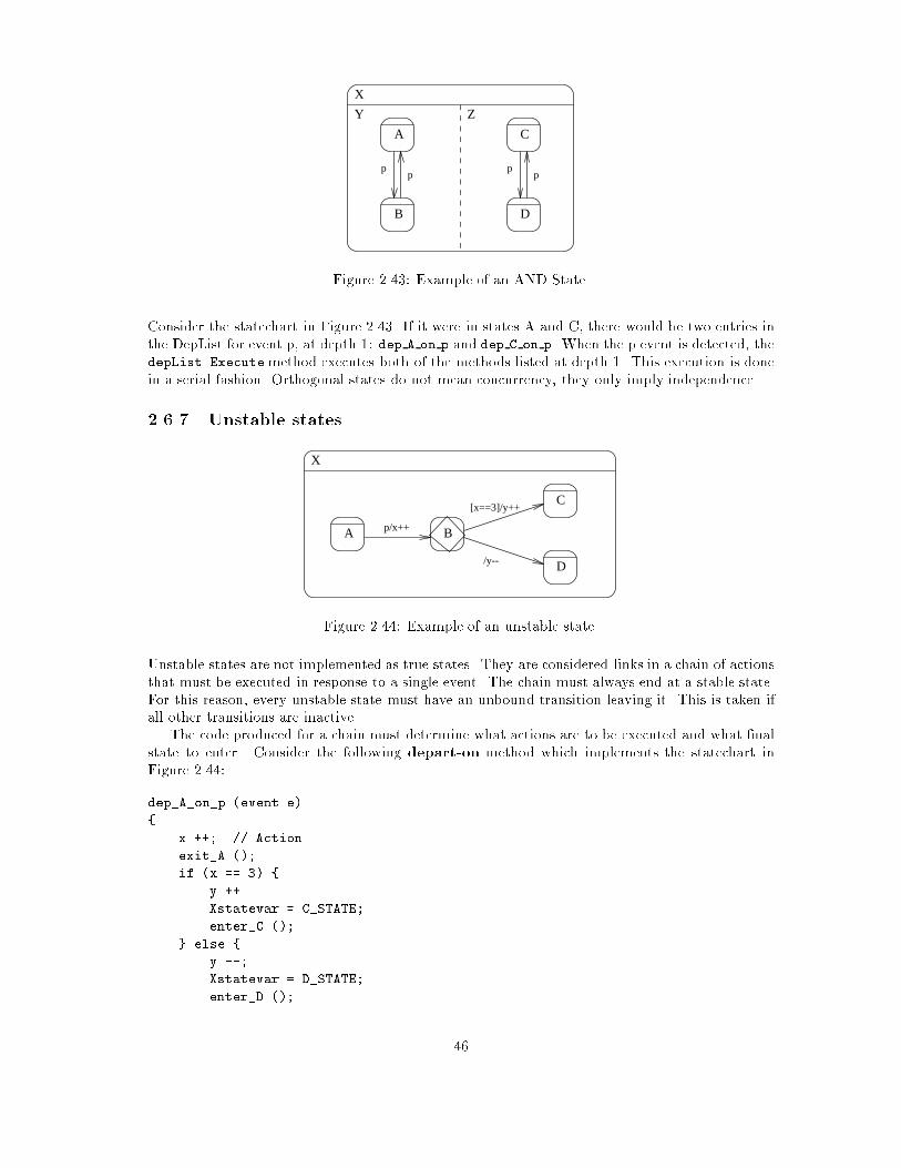
A
B
C
D
X
pp
pp
Y Z
Figure 2.43: Example of an AND State.
Consider the statechart in Figure 2.43. If it were in states A and C, there would be two entries in
the DepList for event p, at depth 1: dep A on p and dep C on p. When the p event is detected, the
depList.Executemethod executes both of the methods listed at depth 1. This execution is done
in a serial fashion. Orthogonal states do not mean concurrency, they only imply independence.
2.6.7 Unstable states
A B
C
X
p/x++
D
[x==3]/y++
/y--
Figure 2.44: Example of an unstable state.
Unstable states are not implemented as true states. They are considered links in a chain of actions
that must be executed in response to a single event. The chain must always end at a stable state.
For this reason, every unstable state must have an unbound transition leaving it. This is taken if
all other transitions are inactive.
The code produced for a chain must determine what actions are to be executed and what �nal
state to enter. Consider the following depart-on method which implements the statechart in
Figure 2.44:
dep_A_on_p (event e)
{
x ++; // Action
exit_A ();
if (x == 3) {
y ++
Xstatevar = C_STATE;
enter_C ();
} else {
y --;
Xstatevar = D_STATE;
enter_D ();
46

}
return (1);
}
2.6.8 Non-determinism
Pure non-determinism, where more than one transition is active from a state at one time, is
removed by simply ignoring all but one of the transitions at code generation. The resulting code
represents a statechart with only one transition, which is deterministic.
B
C
A
X
p[x==1]/y++
p[y==3]/y--
Figure 2.45: Example of Potential Non-determinism.
Potential non-determinism, where many transitions from a state may be active at the same
time depending on their constraints, is dealt with by the depart-on method. The �rst active
transition found is taken, and all the others are ignored. Consider the following example, which
implements the depart-on method for Figure 2.45.
dep_A_on_p (event e)
{
if (x == 1) {
y ++; // Action
exit_A ();
Xstatevar = C_STATE;
enter_A ();
return (1);
} else if (y == 3) {
y --; // Action
exit_A ();
Xstatevar = B_STATE;
enter_A ();
return (1);
}
return (0);
}
Apparent non-determinism is dealt with by the DepList.Execute()method. The non-determinism
is removed by applying outermost priority. Consider the statechart in Figure 2.46. If in states A
and C, pDepList contains references to methods:
� At depth 1: dep Y on p
� At depth 2: dep C on p and dep Z on p
� At depth 3: dep A on p
47

Y
Y1 Y2
p
C
D
p
Z
F
A B
p[x==2]
p[x==1]E
X
Figure 2.46: Example of Apparent Non-determinism.
Consider the case where x=1. When pDepList.Execute() is called the outermost depart-on
method is evaluated �rst, dep Y on p. As the constraint is satis�ed, the transition will be taken.
However, one of the things that dep Y on p does is to call exit Y, which removes all the other
depart-on methods from the pDepList. This means that no further transitions will be evaluted,
and the desired a�ect is achieved.
However, if x=2 then the outermost transition will fail (return zero), so pDepList.Execute()
must execute both dep C on p and dep Z on p. The execution of one will not a�ect the execution
of the other, as they are orthogonal. As dep Z on p succeeds, exit Z will remove dep A on p, so
it will never be processed.
The �nal case is if x=3. The dep Z on p method will fail, so it will not remove dep A on p,
which is then executed. The transition from C to D will be taken regardless of whether x=2 or
x=3.
While it is desirable to have the pDepList.Remove() calls register within the pDepList imme-
diately, it is not desirable to have the pDepList.Add() calls register, as it could mean that the
Execute may perform more calls that is required. So the �rst thing the Execute() method must
do is ensure that Add() calls delay the registration of new depart-onmethods until the Execute()
cycle is complete. So the Add() method simply notes the details, and leaves the work of adding
them to Execute() when it is complete.
2.6.9 Summary
The generation of C++/ECO code that e�ectively models an Entity de�nition is a complex process.
This section has presented an approach that may be taken to the mapping from the higher level
concept of an Entity (with statecharts, actions and events) down to the lower level concept of a
C++/ECO class (with events, pre-conditions and methods).
48

Chapter 3
ECOlib: Support For Events,
Constraints, and Objects
3.1 Introduction
This chapter describes the interface to the ECO library (ECOlib) and contains some details about
its implementation. The library provides low-level runtime support for inter-object communication
based on events and constraints, and as such it is a part of the Moonlight VOID shell.
This introductory section brie y and informally describes the ECO programming model. It
also gives the assumptions about the underlying system and assumptions about the ECOlib user.
The following section speci�es the ECOlib primitives and prede�ned events. The ECOlib is being
implemented, and in several places in this chapter we list the possible implementations of some
part of the interface. The last section summarises the preceding text and mentions some future
work.
3.1.1 Programming with events, constraints, and objects
In the ECO model objects communicate among themselves using events and constraints. An event
represents something that can happen, and it has name and zero or more parameters. The name
of an event allows the objects to refer to a speci�c event among all the events. The parameters of
an event have type (e.g., an integer or a character string). For the speci�c occurrence of an event
the parameters are instantiated with values. These values, together with the event name, describe
to the objects what happened, i.e., describe the speci�c occurrence of an event1.
An object encapsulates some data and some processing. An object can tell other objects about
something that happened, and it can react if it is told by other objects that something happened.
The former is accomplished by announcing an event, and the latter by binding a method of the
object to the required event. This binding can be dynamic, i.e., it is allowed to unbind a method
from an event. The same method can be bound to several events, and the same event can have
several methods (of the same or of di�erent objects) bound to it. A binding can be established
only if the signatures of the event and of the method match (if they have the same number of
parameters, and the types of the corresponding parameters are the same).
Constraints enable more exible event-method bindings and more exible processing of event
noti�cations. An object may conditionally be interested in some event: it is interested only if the
speci�c event parameter has a speci�c value or any value from a range of values when the event
is announced. This can be expressed using the so called Notify constraints. In addition to this,
1In the following text we use \event" for both an event and an event occurrence. The context will indicate thecorrect interpretation.
49
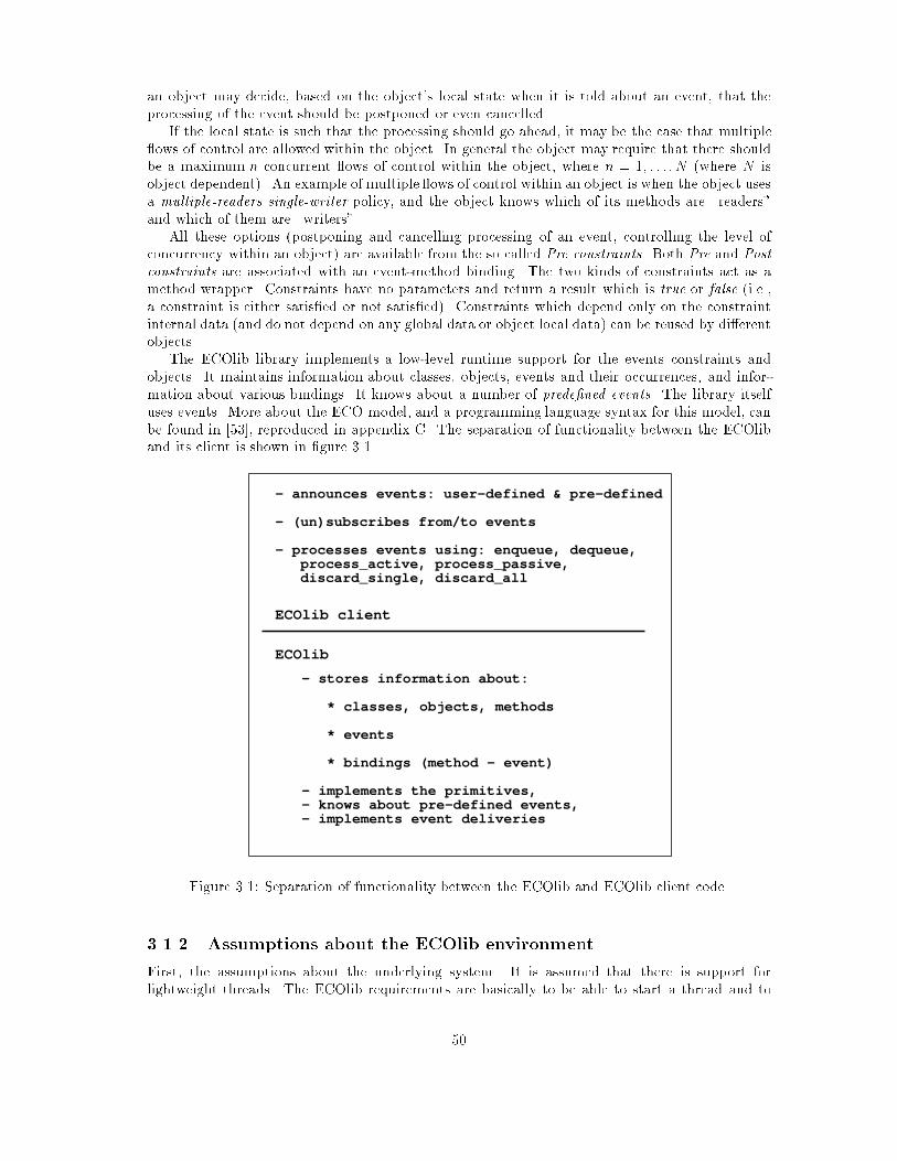
an object may decide, based on the object's local state when it is told about an event, that the
processing of the event should be postponed or even cancelled.
If the local state is such that the processing should go ahead, it may be the case that multiple
ows of control are allowed within the object. In general the object may require that there should
be a maximum n concurrent ows of control within the object, where n = 1; : : : ; N (where N is
object dependent). An example of multiple ows of control within an object is when the object uses
a multiple-readers single-writer policy, and the object knows which of its methods are \readers"
and which of them are \writers".
All these options (postponing and cancelling processing of an event, controlling the level of
concurrency within an object) are available from the so called Pre constraints. Both Pre and Postconstraints are associated with an event-method binding. The two kinds of constraints act as a
method wrapper. Constraints have no parameters and return a result which is true or false (i.e.,a constraint is either satis�ed or not satis�ed). Constraints which depend only on the constraint
internal data (and do not depend on any global data or object local data) can be reused by di�erent
objects.
The ECOlib library implements a low-level runtime support for the events constraints and
objects. It maintains information about classes, objects, events and their occurrences, and infor-
mation about various bindings. It knows about a number of prede�ned events. The library itself
uses events. More about the ECO model, and a programming language syntax for this model, can
be found in [53], reproduced in appendix C. The separation of functionality between the ECOlib
and its client is shown in �gure 3.1.
ECOlib
ECOlib client
- announces events: user-defined & pre-defined
- (un)subscribes from/to events
- processes events using: enqueue, dequeue, process_active, process_passive, discard_single, discard_all
- stores information about:
* classes, objects, methods
* events
* bindings (method - event)
- implements the primitives, - knows about pre-defined events, - implements event deliveries
Figure 3.1: Separation of functionality between the ECOlib and ECOlib client code.
3.1.2 Assumptions about the ECOlib environment
First, the assumptions about the underlying system. It is assumed that there is support for
lightweight threads. The ECOlib requirements are basically to be able to start a thread and to
50
ensure mutual exclusion of threads. It is also assumed that there is preemptive scheduling of
threads, and that this is required by applications.
Next, assumptions about ECOlib`s users. The intended client of ECOlib (i.e., the user of the
interface described in this chapter), is the code which will be generated by a language processor
or by one of the Moonlight tools. The following is assumed:
� When an object is created, the client will allocate the space for object data and assign a unique
identi�er to the object. The ECOlib will be informed about the creation of each object, if
this object is to use events and constraints. This is done using the announce primitive, and
the name of the event announced is object created (one of the prede�ned events).
� In a class-based language a class can play several roles. It is assumed here that a class allows
method sharing and interface sharing for the objects or instances of a class. When a class is
created the ECOlib is informed about this, and is passed some information about that class
(the client announces the class created prede�ned event).
� When a class, or an object, is deleted the ECOLib is informed about this (the client announces
the appropriate prede�ned event).
� Binding between methods of an object and events is dynamic and based on the use of sub-
scribe and unsubscribe. The user of ECOlib is responsible for creating these bindings, and
later for modifying them. Speci�cally, there is prede�ned event called error, which is an-
nounced internally by the ECOlib when some error conditions are detected. This event is
delivered only to those objects which established a binding for the event.
� When an event is announced and the event has parameters then it is up to the user of ECOlib
to marshal the parameters into a single block of memory. A pointer to this block is passed
to ECOlib when the event is announced. When an event is being delivered to a method, a
pointer to a block of memory which contains the event parameters is passed to the method.
It is up to the method to unmarshal these parameters and invoke the application level code
which implements the method.
Di�erent programming language constructs (from the same language or from di�erent lan-
guages) may be translated into the code which will use the ECOlib interface. There is an obvious
mapping from the language constructs described in [53] and the primitives and prede�ned events
described in this chapter.
3.2 The ECOlib interface
This section speci�es the ECOlib entry points or primitives, and a collection of the prede�ned
events.
3.2.1 The ECOLib internals
This subsection describes some internal ECOlib data (the event noti�cation packet, current object,current method, and current event). They are given only in order to simplify the interface desciption
which follows. The implementation of the ECOlib is not constrained in any way by the given
speci�cation of its internal data.
The ECOlib maintains information about the current object, current method, and current
event. This internal information is used by some of the primitives. The event noti�cation packet
(ENP) is also internal to the ECOlib, i.e., it is not visible at the ECOlib interface. Whenever an
event is announced the ECOlib creates an event noti�cation packet which is outlined below.
51

struct enp { /* event notification packet */
char* name_enp; /* name */
enpbody data_enp; /* parameter values */
}
An ENP can be shared by a number of destinations, i.e., it can belong to a number of paths (apath links ENPs which belong to a single destination). Thus, the ENPs form a graph structure. An
ENP has, for each of the paths to which it belongs to, information about the priority of the ENP
relative to other ENPs on the same path. These priorities, if they are used, order the noti�cations
before they are delivered to their destination. The ENPs on a single path are called the readyENPs. Each binding between a method and an event can have its list of waiting ENPs | those
which are managed by the object itself using the enqueue and dequeue primitives (these primitives
are described below).
3.2.2 The primitives of the interface
A list of the primitives is given below. More information about each of them can be found in the
following text.
� announce event name(param value, param value, : : :) priority
� subscribe method name(event name, notify name, pre name, post name)
� unsubscribe method name event name
� process passive
� process active priority
� enqueue
� dequeue method name, event name
� discard single
� discard all
announce is the main primitive of this interface, it can be called from methods and from Pre and
Post constraints. The implementation of some of the other primitives use event announcement,
speci�cally subscribe and unsubscribe are syntactic sugar | they are implemented as announce-
ments of the corresponding internal events (this is done in order to simplify concurrent handling
of \ordinary", i.e., application-speci�c, events and handling of subscribe and unsubscribe). The re-mainder of the primitives from the list are expected to be called fromPre and fromPost constraints.
The primitives which can be called from Pre constraints are: process passive, process active, en-queue, dequeue, discard single, and discard all. The primitives which can be called from Post
constraints are: enqueue, dequeue, discard single, and discard all (note that there is an implicit
discard single after a Post constraint). The users a�ect the order in which the events happen
(i.e., the order in which the events are announced and handled) by using priorities. More about
priorities is given in 3.2.2.1. A speci�cation of the above primitives in the form of a C++ class2 is
given below.
2The use of C++ for the speci�cation of this interface does not indicate that the C++ object model lies underthe Moonlight object model.
52
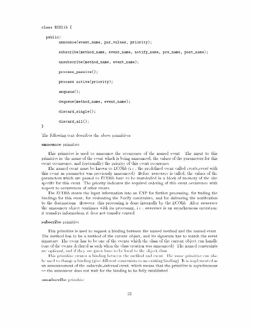
class ECOlib {
public:
announce(event_name, par_values, priority);
subscribe(method_name, event_name, notify_name, pre_name, post_name);
unsubscribe(method_name, event_name);
process_passive();
process_active(priority);
enqueue();
dequeue(method_name, event_name);
discard_single();
discard_all();
}
The following text describes the above primitives.
announce primitive
This primitive is used to announce the occurrence of the named event. The input to this
primitive is: the name of the event which is being announced, the values of the parameters for this
event occurrence, and (optionally) the priority of this event occurrence.
The named event must be known to ECOlib (i.e., the prede�ned event called create event withthis event as parameter was previously announced). Before announce is called, the values of the
parameters which are passed to ECOlib have to be marshalled in a block of memory of the size
speci�c for this event. The priority indicates the required ordering of this event occurrence with
respect to occurrences of other events.
The ECOlib stores the input information into an ENP for further processing: for �nding the
bindings for this event, for evaluating the Notify constraints, and for delivering the noti�cation
to the destinations. However, this processing is done internally by the ECOlib. After announcethe announcer object continues with its processing, i.e., announce is an asynchronous operation:
it transfers information, it does not transfer control.
subscribe primitive
This primitive is used to request a binding between the named method and the named event.
The method has to be a method of the current object, and its signature has to match the event
signature. The event has to be one of the events which the class of the current object can handle
(one of the events declared as such when the class creation was announced). The named constraints
are optional, and if they are given have to be local to the object class.
This primitive creates a binding between the method and event. The same primitive can also
be used to change a binding (give di�erent constraints to an existing binding). It is implemented as
an announcement of the subscribe internal event, which means that the primitive is asynchronous
| the announcer does not wait for the binding to be fully established.
unsubscribe primitive
53

This primitive is used to break the binding between the named method of the current object
and the named event. It is implemented as an announcement of the unsubscribe internal event.There are several options for an implementation of this primitive: (1) all the noti�cations which
may be enqueued on the given binding are discarded, (2) unsubscribe only if there are no out-
standing noti�cations, and (3) if there are outstanding noti�cations wait until they are processed
and discarded and then unsubscribe.
process passive, process active primitives
These two primitives are intended to be called from a Pre constraint and to terminate the Pre
constraint in which they occur. The primitives call the method of the current object passing to it
a pointer to the block of parameters, and the address of the Post constraint. The called method
unmarshalls the parameters, executes the application code, and after that calls the Post constraint.
In the case of process active a new thread is created to execute the method.
The \passive" attribute means that the object allows an external thread of control to \enter"
into the object and execute the given method (i.e., the object appears to be passive). In the case of
process active, the object allows a new thread of control to be created to execute the given method
(optionally, a priority can be speci�ed for this thread). Note that for an object to be \passive" it
is not su�cient that it uses process passive in its Pre constraints. In addition to this the object's
environment must never attempt concurrent deliveries, i.e., the ECOlib must not o�er in parallel
two event noti�cations to the same object. In other words, being passive is not a local property of
an object, it is a property of an object plus its environment. The ECOlib satis�es this requirement,
i.e., it never attempts two deliveries to the same object in parallel. This allows an object to have
a full control over the level of concurrency within the object.
enqueue, dequeue primitives
The enqueue primitive is intended to be called from a Pre constraint to enqueue the current
ENP on the queue of waiting ENPs of the current method. A call to enqueue s intended to
terminate the processing of the Pre constraint in which it occurs. The enqueued ENP will be
processed later, after it is dequeued by calling the dequeue primitive.
The dequeue primitive is intended to be called from a Pre or from a Post constraint. It dequeues
the �rst ENP from the queue of waiting ENPs of the named method of the current object. This
ENP is enqueued (according to its priority) into the queue of ready ENPs for this method.
discard single, discard all primitives
These two primitives are intended to be called from a Pre constraint to explicitly discard the
current ENP. They will both terminate the processing of a Pre constraint. The discard singleprimitive discards the current ENP for the current method of the current object. The same ENP
remains remembered by the ECOLib to be delivered to other destinations. The discard all primitive
removes the current ENP for all the destinations which have not already been delivered the same
ENP. If some destination has already been delivered this ENP (and possibly enqueued the ENP
for later processing), the ENP of this destination is not discarded.
An example which illustrates this is: an event happens and a number of objects are interested
to be informed about this. Some object is told about the event, it does some processing, and the
event noti�cation for this object is discarded. Some other object is told about the same event and
it decides to enqueue the noti�cation for later processing (conceptually this noti�cation is now in
the object's \private space"). Finally some other object is told about the same event and it calls
discard all from a Pre constraint. This has the e�ect that the noti�cation of this event for this
object and for all the other objects which have not already seen this noti�cation are discarded.
Note that there is an implicit discard single after an event noti�cation is delivered, and after
the corresponding Post constraint is run.
54

3.2.2.1 Priorities
The users can indicate to the ECOlib the priority of an event and priority of an event announcement.
A priority is an integer from the [0; : : : ;MAXPRI] range, where 0 denotes the smallest and
MAXPRI denotes the highest priority (a priority may be \not used", which is denoted by a special
value NOPRI). The next paragraphs summarise when a priority may be speci�ed, the meaning
of these priorities, and the default priority in each case (i.e., the priority value chosen if the user
speci�es NOPRI).
� An event can be given priority when create event is announced. If not given, the event is
given the lowest priority by default. This priority is inherited by the event announcements
(if it is not overridden).
� An event announcement can be given priority when the announcement is made. If not given,
the announcement is given the priority of the event by default. This priority indicates to
ECOlib how to order all the event noti�cations, and as a special case, all the noti�cations of
the same event bound to the same destination.
� process active can specify a priority for the thread which is to execute the method. If not
given, the thread inherits the priority of the event by default. This priority can be used by
the thread scheduler3 to determine the order in which the threads are executed.
3.2.3 The prede�ned events
There is a small number of prede�ned events, their names and their intended usage are given below.
� create class, announced when a new class is created to inform the ECOlib about this new
class,
� destroy class, announced when an existing class is deleted,
� create object, announced when a new object is created to inform the ECOlib about this new
object,
� destroy object, announced when an existing object is deleted,
� create event, announced when a new event is created to inform the ECOlib about the name
and parameters of this new event,
� destroy event, announced when an existing event is deleted (it is not possible to delete a
prede�ned event),
� error, announced when an error condition has been detected.
There are also some prede�ned events internal to the ECOlib. Most of the above prede�ned events
are announced by the ECOlib client to inform the ECOlib that a class or object instance or event
is created or destroyed. The error event is announced by the ECOlib when some error has been
detected.
The ECOlib creates neither objects nor classes | it is up to the user to do the necessary work
(for example, to allocate the space for an object and initialise some data and control information,
like class/object identi�er), and to inform the ECOlib about this. The ECOlib handles these
prede�ned events and initialises its internal state based on the information passed to it.
The following text describes the above prede�ned events and two of the ECOlib internal events
(announced by the ECOlib). For each of the prede�ned events we give the event name and
parameters. Users can create their own events, di�erent from the prede�ned events, and use
3Assuming the underlying thread manager supports prioritised threads.
55

the ECOlib to announce them, subscribe to them, etc. The ECOlib has internal data structures
similar to the structures given below (it adds some extra �elds to these structures, for example
the links between the structures, and the locks used to protect the structures from the concurrent
accesses).
create class event
This prede�ned event is announced when a new class is created. The event parameter is the
class descriptor (CD) shown below.
struct cd { /* class descriptor */
char* name_cd; /* class name */
int id_cd; /* class ID */
md md_cd[M1]; /* method descriptors */
cond notify_cd[M2]; /* notify constraint descriptors */
cond pre_cd[M2]; /* pre constraint descriptors */
cond post_cd[M2]; /* post constraint descriptors */
char* ine_cd[M3]; /* names of inevents */
char* oute_cd[M3]; /* names of outevents */
}
The inevents and outevents are the events which the class is prepared to handle and to announce(i.e., the names of events which the class may announce, and to which it may bind its methods).
These events have to be known to ECOlib when create class is announced. A class descriptor
contains a method descriptor (MD) for each of the class methods, and a constraint descriptor(COND) for each of the class constraints (Notify, Pre, and Post constraints). M1, M2, and M3
are the ECOlib con�guration parameters. M1 is the maximum number of methods per class, M2
is the maximumnumber of each of Notify/Pre/Post constraints per class, andM3 is the maximum
number of each of inevents/outevents per class.
struct md { /* method descriptor */
char* name_md; /* method name */
void* add_md; /* method code memory address */
pd pd_md[M4]; /* parameter descriptors */
}
A method descriptor contains a parameter descriptor (PD) for each of the method parameters.
M4 is the maximum number of parameters per method.
struct pd { /* parameter descriptor */
char* name_pd; /* name */
int size_pd; /* size */
int type_pd; /* type ID */
}
struct cond { /* constraint descriptor */
char* name_cond; /* name */
void* add_cond; /* code memory address */
}
56

The type of a method parameter is an identi�er passed to the ECOlib. It is used when a method-
event binding is esatblished to check if the method and event signatures match (the ECOlib does
not assign any meaning to these type identi�ers and is only interested in the total size of the
method/event parameters, in addition to testing if two type identi�ers are equal).
destroy class event
This prede�ned event is announced when an existing class is destroyed. The event paramater
is the name of the class which is destroyed. An implementation of the event handler for this event
may: (1) destroy any record of this class only if currently there are no instances of the class, or (2)
destroy any record of the class in any case. If the second option is used and there are some instances
of the deleted class, this may cause an error condition to be detected when the information from
the deleted class is required by these instances.
create object event
This prede�ned event is announced when an object is created. The event parameter is the
object descriptor (OD) shown below plus the name of the object's class.
struct od { /* object descriptor */
int objid_od; /* ID */
mid mid_od[M1]; /* method descriptors */
}
struct mid { /* object method descriptor */
void* add_mid; /* code memory address */
ebd ebd_mid[M5]; /* bindings to events */
}
struct ebd { /* method-event binding descriptor */
void* notify_ebd; /* notify address memory address */
void* pre_ebd; /* pre constraint memory address */
void* post_ebd; /* post constraint memory address */
}
The ECOlib maintains for each object and for each method of the object the bindings between
the method and events. This information is held in the event binding descriptor (EBD) for each of
the events to which the method is subscribed. An EBD contains information about the constraints
associated with the binding. The con�guration parameter M5 is the maximum number of events
to which a single method may be simultaneously bound.
destroy object event
This prede�ned event is announced when an existing object is destroyed. The event parameter
is the ID of the object which is destroyed. Similar to destroy class, an implementation of the
handler for this prede�ned event may: (1) destroy the record of this object only if currently there
are no bindings of the object's methods to any events, or (2) destroy the record of this object
only if there are no outstanding event noti�cations for this object, or (3) destroy the record of this
object in any case, discarding any possible outstanding event noti�cations.
57
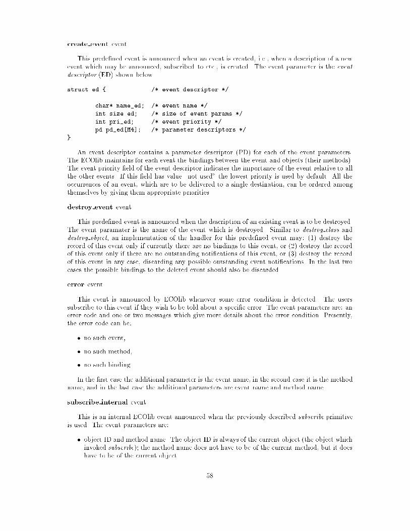
create event event
This prede�ned event is announced when an event is created, i.e., when a description of a new
event which may be announced, subscribed to etc., is created. The event parameter is the eventdescriptor (ED) shown below.
struct ed { /* event descriptor */
char* name_ed; /* event name */
int size_ed; /* size of event params */
int pri_ed; /* event priority */
pd pd_ed[M4]; /* parameter descriptors */
}
An event descriptor contains a parameter descriptor (PD) for each of the event parameters.
The ECOlib maintains for each event the bindings between the event and objects (their methods).
The event priority �eld of the event descriptor indicates the importance of the event relative to all
the other events. If this �eld has value \not used" the lowest priority is used by default. All the
occurrences of an event, which are to be delivered to a single destination, can be ordered among
themselves by giving them appropriate priorities.
destroy event event
This prede�ned event is announced when the description of an existing event is to be destroyed.
The event paramater is the name of the event which is destroyed. Similar to destroy class anddestroy object, an implementation of the handler for this prede�ned event may: (1) destroy the
record of this event only if currently there are no bindings to this event, or (2) destroy the record
of this event only if there are no outstanding noti�cations of this event, or (3) destroy the record
of this event in any case, discarding any possible outstanding event noti�cations. In the last two
cases the possible bindings to the deleted event should also be discarded.
error event
This event is announced by ECOlib whenever some error condition is detected. The users
subscribe to this event if they wish to be told about a speci�c error. The event parameters are: an
error code and one or two messages which give more details about the error condition. Presently,
the error code can be:
� no such event,
� no such method,
� no such binding.
In the �rst case the additional parameter is the event name, in the second case it is the method
name, and in the last case the additional parameters are event name and method name.
subscribe internal event
This is an internal ECOlib event announced when the previously described subscribe primitive
is used. The event parameters are:
� object ID and method name. The object ID is always of the current object (the object which
invoked subscribe); the method name does not have to be of the current method, but it does
have to be of the current object.
58

� event name. The name of the event to which the method subscribes.
� Notify constraint name, Pre constraint name, and Post constraint name. These names are
optional, and if given have to be local to the class of the current object.
unsubscribe internal event
Similar to subscribe internal this is an internal ECOlib event, announced when the unsubscribeprimitive is invoked. The event parameters are: object ID and method name (the same restrictions
are valid here as in the case of subscribe internal), and event name.
3.3 Summary
This chapter describes the ECOlib interface and the assumptions about the environment in which
this library is used. It is obvious that in some cases there may be tighter coupling between the
ECOlib code and the rest of the VOID shell. For example, in some cases a method address or an
event identi�er may be passed to a primitive instead of a character string being passed a for method
name or event name. In other cases, it may be known that no object will ever use process active,and that ECOlib can relax some of its assumptions about the possible concurrent accesses to some
data structures. This would allow ECOlib to be implemented more e�ciently.
The ECOlib described in this chapter is being implemented for a single address space, multi-
threaded environment. In future it will be extended to support multiple address spaces and multiple
nodes connected over a network.
59

Chapter 4
The VOID Libraries
4.1 Introduction
The VOID libraries are a a key part of the MOONLIGHT strategy for improving productivity in
the development of video-game and virtual world programs. The libraries provide a uni�ed and
consistent interface to the various kinds of functionality that are required, such as two and three
dimensional graphics, input control, detection of collision between entities in the virtual world and
so on.
The libraries are one of three parts to the uni�ed solution that TCD is proposing, the other
parts being:
� an Entity Editor tool capable of automatic generation of application code from a graphical
notation (statecharts);
� run-time support, called ECO, for event-based programming.
In the text below we describe the relationship between the VOID libraries and these other
components.
Relationship to Entity Editor One of the key points in our approach to rapid prototyping
of video games and virtual worlds is the use of a graphical notation to specify the behaviour of
the entities. The VOID libraries are the key to allowing these speci�cations to become prototypes:
they provide the code that is used to provide functionality for entities. By framing the various
underlying software packages (such as GUL, SUL, etc) in a consistent, object-oriented C++ library
the Entity Editor tool will be able produce working programs automatically.
Relationship to ECO The VOID libraries are basically independent of (but compatible with)
the ECO library, at least in this initial release. In e�ect the VOID libraries and the ECOlib form
twin supports for the Entity Editor. This is because programs written using statecharts need the
event support provided by the ECOlib. If these event-based programs are video-games then they
will also require the functionality provided by the VOID libraries.
Relationship to ECOsim In this release of the libraries we include a library called ECOsim,
which contains some simple class-based support for event-based programming. The purpose of
this library is to allow development of programs using the libraries in advance of completion of the
ECO model.
The class support is neither particularly e�cient nor fully-featured, but it does o�er a signi�cant
advantage over programming in straight C++: namely that it is not straight C++. Programs
written using the standard models of invocation and named addressing of C++ will have a very
60

di�erent structure to those developed using events. Therefore, if code developed using the early
versions of the libraries is to be of any use subsequently it should be developed using an event-based
approach.
4.2 Contents
This chapter provides a description of the structure and functionality of the libraries as well as a
snapshot of the interfaces of the current release (the libraries themselves are undergoing constant
extension). Included in Appendix B is a description of the ECOsim library and some examples of
its use.
4.3 Structure of the libraries
There are both quite a number of individual libraries and (potentially) several instances of each
library, arising from two motivations:
� MOONLIGHT has several target platforms;
� the functionality required for videogames and virtual worlds has several distinct parts (sound,
graphics, video, entity interaction etc.)
4.3.1 Rami�cations of multiple target platforms
The desire to support multiple hardware platforms may make it necessary to have several versions
of any given library. This is more than a matter of using di�erent compilers. If all the code
is platform independent then the di�erent versions would indeed di�er only in the compiler. In
practice, however, some of the the code will be platform speci�c to take advantage of the hardware.So for example, if the target platform for a given application is a PC which contains the MOONLIGHT
board then the program should be linked with a library which drives this board. If, on the other
hand the target platform is a PC without any graphics hardware then the same program could be
linked with a library which provides software emulation for the graphics functions.
4.3.2 Rami�cations of functional divisions
The second partitioning in uence on the libraries is the desire to pick and mix functionality on a
per application basis. For example, in an application in which the sound is relatively uncomplicated
then one would wish to avoid using a heavyweight sound library.
It would of course be possible to create a single, monolithic library with all the functionality
that could ever be used in a video game or virtual world, but it would not be very good software
engineering, due to the increased size and, inevitably symbol name clashes. Especially in a video
game where the cost of the unit is strongly related to the size of the memory and where speed is
also extremely important. Of course, even in a monolithic library only the necessary object �les are
linked, but then programmer must rely on the library's author and, more importantly maintainers,
to maintain the internal divisions.
4.4 Platform and products
Naturally, not all of the libraries will exist on every platform because some are intrinsically platform
speci�c. To complicate matters further the same library may have di�erent names on di�erent
platforms due to the restrictions of the OS or the compiler.
61

De�nition The concept of a \product" is borrowed from [35] and describes a particular output
of a compilation or link process. Every library in the VOID system is a product, some libraries
represent more than one product because they are present on several platforms.
The relationship between platforms and products for some representative libraries in the VOID
system is illustrated by Table 4.1 below. The table shows the �ve directories associated with the
production of eight graphics library products on (currently) three platforms. To these will later be
added platforms for the MOONLIGHT arcade board and possibly other MS-DOS or Unix compilers.
Product dir product(s) platforms description
graphics/gl.lib libvoidgl.a irix4cc C++ wrappers for gl
graphics/gulsoft.lib libvoidguls.a irix4cc C++ wrapper for gul
libvguls.lib watcom software-only versions
libvoidguls.a (TWS)
graphics/gulhard.lib libvgulh.lib watcom C++ wrapper for gul
libvoidgulh.a (TWS) with hardware assist
graphics/ABCs.ini (headers) (shared) C++ header �les
for all versions of
library voidg
graphics/ABCs.lib libvoidg.a irix4cc base class code for
libvoidg.lib watcom void graphics
input/ABCs.ini (headers) (shared) C++ header �les for
input control
Figure 4.1: VOID libraries and platform: the current status
Managing this source is a complex business which requires strict demarcation between platform
dependent and platfrom independent source. This separation is integrated with our OO approach
through the use of a library of Abstract Base Classes (ABCs) which enforce interfaces and which
represent an abstract framework which the platform speci�c code implements.
4.5 Functionality
As mentioned elsewhere (x4.1) an important intended client of the VOID libraries is the (code
generated by the) Entity Editor tool. The libraries should ideally provide everything that the user
of the Entity Editor does not. There are two aspects to the functionality required by this machine
generated code. Firstly the entities will require a basic set of functions which will provide the
\vocabulary" that is usable for the speci�cation of event handlers in the Entity Editor. Secondly,
the application will obviously require much functionality beside that which is held in the game
entities: such things as graphics libraries and sound drivers.
A distinction can therefore be drawn between the means in which the libraries functionality
is brought to the application, either by inheritance or in a client-server fashion. This amounts to
the same distinction as described in previous documents[17][57]) between Standard Objects and
Generic Classes.
Standard Objects include all those classes which are necessary to provide the ancilliary
functionality which is used in the application but which is not part of any Entity. This includes
functionality that is outside of all Entities (eg. I/O, 3D rendering) and functionality that exists
between Entity instances (eg. perception, collision etc).
Generic Objects allow access to library functionality through invocations of Base Class meth-
ods. This allows the actions of these Game Entities to be written using these Base Class methods.
62

Generic classes thus provide small, comprehensible interfaces to the Standard Objects. Compre-
hensibity is bought at the price of restricting the expressive power of the Standard Objects in
certain ways. These restrictions do not, however, impede the application programmer because the
Generic Classes are tailored to provide the most useful functionality for writing video games and
virtual worlds.
This division is (only) conceptual: it is useful for categorisation and description. It also marks
an important division of learning: the application programmer need only know about the Generic
Classes. However it should be noted that at the source code level the two groups are quite tightlybound together. This is because the Generic Objects act as interfaces to the more complicated
Generic Objects, and the implementation of the Generic Classes is therefore strongly related to
the implementation of the Standard Objects.
Where the classes provided prove insu�cient the solution is to add a new Generic Class to
the library rather than to \work around" the existing Generic Classes to get at the Standard
Objects directly. This method promotes re-use and program correctness, without impeding a
rapid development because it is basically a stuctural change not a procedural one. The code must
be written in any case, but by writing it into the library it is available for re-use.
4.6 Design diagrams
4.6.1 Using inheritance for multi-platform support
Figure 4.2 shows the pattern of inheritance in this library: each Abstract Base Class (ABC) has
(at least one) concrete child class. There is one concrete class for each platform that must be
supported, in this diagram we show the child classes which support the GUL version of the VOID
graphics library, and two unnamed alternative implementations.
All of these child-classes must, of course, conform to the interface speci�ed in the ABCs
(although they are free to extend it). This means that applications written to use the ABCs
may be ported to other platforms without change to their code, and that cross-platform develop-
ment/prototyping is possible.
4.6.2 Generic types and simpli�ed interfaces
Figure 4.3 shows some of the complex inter-relations between the classes that make up one of the
VOID libraries, the GUL implementation of the graphics library. It is important to emphasise that
the complexity of this diagram is hidden from VOID clients, through the divsion between Standard
Objects and Generic Classes.
In this library the Generic Class is GraphicObject, and its concrete class is GUL GraphicObject.
It is only this class that VOID library users and client code should have to deal with, as it hides the
complexity of the Standard Objects. This can be seen in Figure 4.4, in which the Abstract Base
Class GraphicObject and its GUL speci�c child-class GUL GraphicObject have been pulled down
below the other classes to show the separation between Generic Classes and Standard Objects.
4.7 Development Strategy
Our approach to developing these libraries has been a synthesis of three approaches:
� object-oriented design and programming;
� encapsulation of existing libraries;
� parallel development of applications.
63

Abstract Classes and their (Multi−Platform) Children
GUL_Perspective
(from s)
View
(from s)
Projection
(from s)
GUL_GraphicObject
(from s)
ActiveList
(from s)
GraphicObject
(from s)Scene
(from s)
Window
(from s) GUL_Camera
(from s)
GUL_Scene
(from s)
Camera
(from s)
GUL_Window
(from s)
GUL_ActiveList
(from s)
alternate child
alternate child
alternate child
alternate child
alternate child
alternate child
alternate child
alternate child
alternate child
alternate child
alternate child
alternate child
Figure 4.2: Inheritance in the graphics libraries
4.7.1 Object oriented design and programming
In addition to doing the design work using OOD, the implementation of the libraries makes exten-
sive use of Object-Oriented techniques:
� Abstract Base Classes have been used to hold the platform-independent interface, with
platform-speci�c incarnations of these classes providing the actual code. This ensures a
consistent interface and functionality for the libraries across platforms
� Class data is entirely encapsulated in all the classes in the libraries and can only be accessed
through the functions of the class interface.
� There are no global variables.
� Functionality that is required for applications is accessed through inheritance of the appro-
priate base Generic Class from the library. The interface to the Generic class in question
then insulates the programmer from both the internals of the library and from some of the
complexity of its structure.
4.7.2 Encapsulating existing libraries
One very important role of the VOID libraries is in hiding the complexities of other software
components of the project and giving a consistent interface to these other components. At present
the only external library that has been available to be included is the Graphic Ultra Light (GUL)
library for 3D graphics (written by Caption). We anticipate adding the Sound Ultra Light interface
as soon as it is available.
Example The GUL library is written in the C language, with a traditional non-OO API. We
have written C++ code (conforming to the VOID graphics library OO design) which wraps1 this
1this involves a lot more than just call-forwarding, see code for details
64

Graphics Library Framework (inheritance, instantiates and has relationships)
GUL_Perspective
(from s)
View
(from s)
AA
Projection
(from s)
AA
GUL_GraphicObject
(from s)
GUL_Matrix
(from s)
ActiveList
(from s)
AA
void_Colour
(from s)
GraphicObject
(from s)
AA
f_Position
(from s) Vector
(from s)
Scene
(from s)
AA
Set<class GraphicObje
(from s)
Window
(from s)
AA
SetItem<class
(from s)
Set
(from s)
SetItem
(from s)
GUL_Camera
(from s)
GUL_Scene
(from s)
Camera
(from s)
AA
Set<class Camera*>
(from s)
SetItem<class Camera*>
(from s)
GUL_Window
(from s)
GUL_ActiveList
(from s)
Rotation
(from s)
Gul_ObjectID
(from <unspecified>)
Screencoord
(from <unspecified>)
InputController
(from <unspecified>)
void_Material
(from <unspecified>)
void_Geometry
(from <unspecified>)
m
1
1
myActiveList
1
1
position1
1
rotation
11
colour
1
1
material1
1
geometry
1
1
entityList
1
1
currentItem1
0..1
front1
0..1
back1
0..1
top
1
1
bottom
1
1
left
1
1
right
1
1
background
1
1
cams
1
1
input10..1
next
1
0..1
previous
1
0..1
currentItem1 0..1
front1 0..1
back1 0..1
next
1
0..1
previous
1
0..1
mount
1
1
projection
1
1
scene 11
offset
1
1
top
1
1
bottom
1
1
left
1
1
right
1
1
currentItem
1
0..1
front
1
0..1
back
1
0..1
next
1
0..1
previous
1
0..1
Figure
4.3:Classrela
tionshipsin
thegraphics
framew
ork
65

Generic Object (GraphicObject) as interface to Standard Objects (all other classes)
GUL_Perspective
(from s)
View
(from s)
AA
GUL_GraphicObject
(from s)
ActiveList
(from s)
AA
void_Colour
(from s)
GraphicObject
(from s)
AA
Scene
(from s)
AA
Set<class GraphicObje
(from s)
Window
(from s)
AA
GUL_Camera
(from s)
GUL_Scene
(from s)
Camera
(from s)
AA
Set<class Camera*>
(from s)
GUL_Window
(from s)
Screencoord
(from <unspecified>)
FF
FF
Type
FF
Type
FF
FF
Figure 4.4: Standard objects/Generic Classes
C API and allows its functionality to be accessed through the Generic Class GUL GraphicObject.
This class is a sub-type of GraphicObjectwhich is an Abstract Base Class from the VOID graphics
library.
4.7.3 Applications
In tandem with the development of the libraries we have been developing an application which is a
version of the arcade game \BattleZone", itself reincarnated recently by NamCo as \CyberSled".
Developing this application serves two purposes. Firstly it greatly facilitates validation of the
functionality of the library. Secondly, where functionality used in the application is not present inthe library (or the library design) we are able to consider whether this functionality is not in the
libraries through omission or because it is application speci�c.
Example Consider a situation that might arise in writing a virtual world simulation. The
application programmer wishes to do collision detection with some three-dimensional shapes, which
are complex in terms of numbers of primitives. It might turn out that the libraries' collision support
was infeasibly slow with such complex shapes, but that a faster algorithm could be found, which
made use of some domain-speci�c simpli�cation (perhaps these complex pieces are being moved in
simple axial-parallel ways).
Once the application programmer had developed this code it could be moved to the collision
66

library as another policy type, embodied in another Generic Base Class. Subsequent programmers
would then have access to this functionality.
4.8 Summary
This chapter has described the development approach, the design and the software architecture of
the VOID libraries.
67

Appendix A
Interfaces to the libraries
A.1 Graphics classes
A.1.1 Abstract Base Classes for graphics
//-�-c++-�-
#ifndef ACTIVELIST HH
#define ACTIVELIST HH
#include "Geometry.hh"
#include "code std.hh"
// de�nes generic interface for active lists (of objects to be rendered),// initially used to support the GUL active list, later this functionality// is to be added to GL version of VOID alsoABSTRACT CLASS ActiveList fpublic:
ActiveList() fg // no ctor as yetvirtual void addToList(void Geometry new obj) = PURE VIRTUAL;
virtual void removeFromList(void Geometry dead obj) = PURE VIRTUAL;
g;
#endif
Figure A.1: ActiveList.hh
A.1.2 Graphics class instantiations for GUL
These de�nitions serve for both both software and hardware versions of GUL on all platforms.
68

//-�-c++-�-
#ifndef GEOMETRY HH
#define GEOMETRY HH
typedef short int void Material;
#ifdef USING GUL
typedef short int void Geometry;
#endif
#ifdef USING GL
typedef Object void Geometry;
#endif
#endif
Figure A.2: Geometry.hh
//-�-c++-�-
#ifndef POSITION HH
#define POSITION HH
#include <math.h>
#include "Vector.hh"
typedef Vector< oat> f Position;
#endif
Figure A.3: Position.hh
69

//-�-c++-�-
#ifndef PROJECTION HH
#define PROJECTION HH
#include "code std.hh"
// The projection virtual base class./������������������������������������������������������������������������������/ABSTRACT CLASS Projection f/������������������������������������������������������������������������������/public:
virtual void apply() = PURE VIRTUAL;
virtual void remove() = PURE VIRTUAL;
g;
#endif
Figure A.4: Projection.hh
//-�-c++-�-
#ifndef ROTATION HH
#define ROTATION HH
#include <math.h>
#include "Vector.hh"
#include "gl.h"
typedef Vector<Angle> Rotation;
#endif
Figure A.5: Rotation.hh
70

//-�-c++-�-
#ifndef VIEW HH
#define VIEW HH
#include "code std.hh"
/������������������������������������������������������������������������������/ABSTRACT CLASS View f/������������������������������������������������������������������������������/friend class Window;
public:
virtual void snapshot() = PURE VIRTUAL;
g;
#endif
Figure A.6: View.hh
71

//-�-c++-�-
#ifndef CAMERA HH
#define CAMERA HH
#include "GraphicObject.hh"
#include "Projection.hh"
#include "Scene.hh"
#include "View.hh"
/������������������������������������������������������������������������������/class Camera : public View f/������������������������������������������������������������������������������/protected:
Screencoord top, bottom, left, right;
public:
Camera(Screencoord, Screencoord, Screencoord, Screencoord);
// �Camera();
virtual void add(GraphicObject �go) = PURE VIRTUAL;
// has to be virtual cos scene is not a component of the base class,// and it currently isn't because it takes di�erent params in// the two variants. This may be �xable later.
virtual void set() = PURE VIRTUAL;
virtual void snapshot() = PURE VIRTUAL;
virtual void setMount(GraphicObject �m) = PURE VIRTUAL;
virtual void O�set(f Position &new o�set) = PURE VIRTUAL;
g;
#ifndef MOONLIGHT OUTLINE
#define INLINE inline
#include "Camera.icc"
#endif
#endif
Figure A.7: Camera.hh
72

//-�-c++-�-
#ifndef SCENE HH
#define SCENE HH
#include "code std.hh"
#include "Set.hh"
#include "GraphicObject.hh"
/������������������������������������������������������������������������������/ABSTRACT CLASS Scene f/������������������������������������������������������������������������������/friend class Window;
friend class View;
protected:
Set<GraphicObject �> entityList;
public:
Scene();
�Scene();
virtual void add(GraphicObject �) = PURE VIRTUAL;
virtual void remove(GraphicObject �) = PURE VIRTUAL;
g;
// no inline functions so far for Abstract class Scene#ifndef MOONLIGHT OUTLINE
#define INLINE inline
//#include "Scene.icc"#endif
#endif
Figure A.8: Scene.hh
73

//-�-c++-�-
#ifndef WINDOW HH
#define WINDOW HH
#include "code std.hh"
#include "InputController.hh"
#include "Camera.hh"
/������������������������������������������������������������������������������/ABSTRACT CLASS Window f/������������������������������������������������������������������������������/friend class GraphicDevice;
protected:
Screencoord top, bottom, left, right;
long windowHandle;
char �windowName;
void Colour background;
Set<Camera �> cams;
InputController � input; // shouldn't be part of the window
virtual void draw() = PURE VIRTUAL;
public:
Window(char � n, void Colour c, Screencoord t,
Screencoord b,Screencoord l,Screencoord r);
�Window();
void setInputControl(InputController �);void add(Camera � v);void remove(Camera � v);
g;
#ifndef MOONLIGHT OUTLINE
#include "Window.icc"
#endif
#endif
Figure A.9: Window.hh
74

//-�-c++-�-
#ifndef GRAPHICOBJECT HH
#define GRAPHICOBJECT HH
#include "code std.hh"
#include "ActiveList.hh"
#include "Geometry.hh"
#include "rgbColour.hh"
#include "Position.hh"
#include "Rotation.hh"
/������������������������������������������������������������������������������/ABSTRACT CLASS GraphicObject f/������������������������������������������������������������������������������/friend class Camera;
protected: // dataf Position position;
Rotation rotation;
void Colour colour;
void Material material;
void Geometry geometry;
protected: // methodsvoid setGeometry(void Geometry obj);
void setColour(void Colour c);
void setMaterial(void Material m);
void setPosition(f Position p);
void setRotation(Rotation r);
Angle xRot();
Angle yRot();
Angle zRot();
oat xPos();
oat yPos();
oat zPos();
public: // methodsGraphicObject(f Position &, Rotation &, ActiveList &, void Geometry &, void Colour,
void Material);
virtual void makeActive() = PURE VIRTUAL; // will be implemented here RSN(TM)virtual void makeInactive() = PURE VIRTUAL; // will be implemented here RSN(TM)virtual void render() = PURE VIRTUAL;
void Geometry getGeometry();
g;
#ifndef MOONLIGHT OUTLINE
#define INLINE inline
#include "GraphicObject.icc"
#endif
#endif
Figure A.10: GraphicObject.hh
75
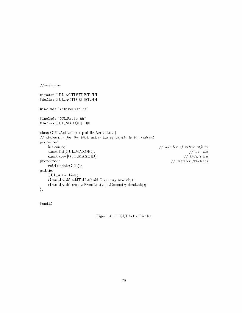
//-�-c++-�-
#ifndef GUL ACTIVELIST HH
#define GUL ACTIVELIST HH
#include "ActiveList.hh"
#include "GUL Proto.hh"
#define GUL MAXOBJ 100
class GUL ActiveList : public ActiveList f// abstraction for the GUL active list of objects to be renderedprotected:
int count; // number of active objectsshort list[GUL MAXOBJ]; // our listshort copy[GUL MAXOBJ]; // GUL's list
protected: // member functionsvoid updateGUL();
public:
GUL ActiveList();
virtual void addToList(void Geometry new obj);
virtual void removeFromList(void Geometry dead obj);
g;
#endif
Figure A.11: GULActiveList.hh
76
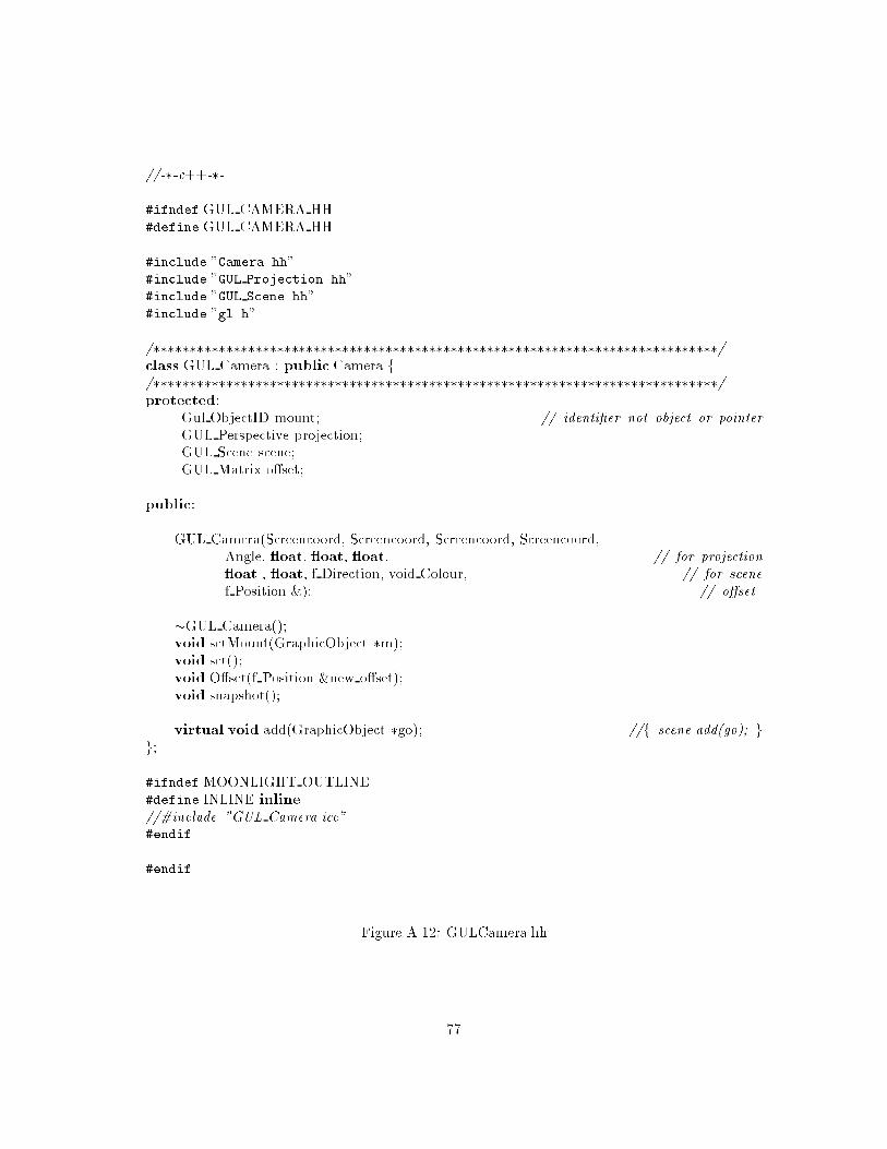
//-�-c++-�-
#ifndef GUL CAMERA HH
#define GUL CAMERA HH
#include "Camera.hh"
#include "GUL Projection.hh"
#include "GUL Scene.hh"
#include "gl.h"
/������������������������������������������������������������������������������/class GUL Camera : public Camera f/������������������������������������������������������������������������������/protected:
Gul ObjectID mount; // identi�er not object or pointerGUL Perspective projection;
GUL Scene scene;
GUL Matrix o�set;
public:
GUL Camera(Screencoord, Screencoord, Screencoord, Screencoord,
Angle, oat, oat, oat, // for projection oat , oat, f Direction, void Colour, // for scenef Position &); // o�set
�GUL Camera();
void setMount(GraphicObject �m);
void set();
void O�set(f Position &new o�set);
void snapshot();
virtual void add(GraphicObject �go); //f scene.add(go); gg;
#ifndef MOONLIGHT OUTLINE
#define INLINE inline
//#include "GUL Camera.icc"#endif
#endif
Figure A.12: GULCamera.hh
77

//-�-c++-�-
#ifndef GUL GRAPHICOBJECT HH
#define GUL GRAPHICOBJECT HH
#include "GUL Matrix.hh"
#include "GraphicObject.hh"
typedef short int Material;
/������������������������������������������������������������������������������/class GUL GraphicObject : public GraphicObject f/������������������������������������������������������������������������������/friend class Camera;
protected: // dataGUL Matrix m;
ActiveList &myActiveList;
public: // methodsGUL GraphicObject(f Position &, Rotation &, ActiveList &, void Geometry &, void Colour,
Material);
virtual void makeActive(); // will migrate to the base class in next passvirtual void makeInactive(); // will migrate to the base class in next passvirtual void render();
g;
#ifndef MOONLIGHT OUTLINE
#include "GUL GraphicObject.icc"
#define INLINE inline
#endif
#endif
Figure A.13: GULGraphicObject.hh
78

//-�-c++-�-
#ifndef GUL MATRIX HH
#define GUL MATRIX HH
#include "Position.hh"
#include "Rotation.hh"
#include <iostream.h>
extern "C" void exit(int);
class GUL Matrix fprotected:
oat m[12];
static oat error;
public:
GUL Matrix();
GUL Matrix( oat f1, oat f2, oat f3, oat f4,
oat f5, oat f6, oat f7, oat f8,
oat f9, oat f10, oat f11, oat f12);
GUL Matrix(const GUL Matrix &v);
GUL Matrix &operator=(const GUL Matrix &v);
oat &operator[](unsigned int i);
GUL Matrix invert();
GUL Matrix operator�(const GUL Matrix &v);
GUL Matrix rotateX(Angle a);
GUL Matrix rotateY(Angle a);
GUL Matrix rotateZ(Angle a);
GUL Matrix translate(f Position &p);
friend ostream& operator�(ostream&, GUL Matrix &);
g;
#ifndef MOONLIGHT OUTLINE
#include "GUL Matrix.icc"
#define INLINE inline
#endif
#endif
Figure A.14: GULMatrix.hh
79

//-�-c++-�-
#ifndef GUL PROJECTION HH
#define GUL PROJECTION HH
#include "Projection.hh"
#include "gl.h"
/������������������������������������������������������������������������������/class GUL Perspective : public Projection f/������������������������������������������������������������������������������/friend class View;
protected:
public:
GUL Perspective(Angle fy, oat a, oat n, oat f);
void apply();
void remove();
g;
#ifndef MOONLIGHT OUTLINE
#include "GUL Projection.icc"
#define INLINE inline
#endif
#endif
Figure A.15: GULProjection.hh
80

#include "GUL Matrix.hh"
typedef Vector< oat> f Direction;
typedef short int Gul ObjectID;
extern "C" f#include "Gul.h"
void Gul SetActiveList(short �, short);void Gul SetCameraAngle(double);
void Gul GetCameraAngle(double�);void Gul SetCameraZClip(double);
void Gul SetCameraDepth(double);
void Gul SetAmbientPower(double);
void Gul SetLightPower(double);
void Gul CreateObject(short �,OBJ �);void Gul ModifyActiveList(CMD �, short);void Gul SetLightDirection(f Direction �);void Gul GetObjectMatrix(short, GUL Matrix �);void Gul SetObjectMatrix(short, GUL Matrix �);void Gul SetViewportColor(COLOR);
void Gul SetCameraMatrix(GUL Matrix �);void Gul GetCameraMatrix(GUL Matrix �);void Gul Render();
void Gul SyncRender();
void Gul SwapFrameBu�er();
void Gul Open(short, short);
void Gul InitObject(short);
g
Figure A.16: GULProto.hh
81

//-�-c++-�-
#ifndef GUL SCENE HH
#define GUL SCENE HH
#include "Scene.hh"
#include "GUL Proto.hh"
#include "gl.h"
#include "rgbColour.hh"
/������������������������������������������������������������������������������/class GUL Scene : public Scene f/������������������������������������������������������������������������������/friend class Window;
friend class View;
public:
GUL Scene( oat l, oat al, f Direction d, void Colour bg);
void setLight( oat l, oat al, f Direction d, void Colour bg);
�GUL Scene();
virtual void add(GraphicObject � go);virtual void remove(GraphicObject � go);
g;
#ifndef MOONLIGHT OUTLINE
#include "GUL Scene.icc"
#define INLINE inline
#endif
#endif
Figure A.17: GULScene.hh
82

//-�-c++-�-
#ifndef GUL WINDOW HH
#define GUL WINDOW HH
#include "Window.hh"
/������������������������������������������������������������������������������/class GUL Window : publicWindow f/������������������������������������������������������������������������������/friend class GraphicDevice;
protected:
virtual void draw();
public:
GUL Window(char � n, void Colour c, Screencoord t,
Screencoord b,Screencoord l,Screencoord r);
�GUL Window();
g;
// no inline functions => no GUL Window.icc#ifndef MOONLIGHT OUTLINE
//#include "GUL Window.icc"#define INLINE inline
#endif
#endif
Figure A.18: GULWindow.hh
83

Appendix B
ECOsim: class support for
event-based programming
B.1 Introduction
This section describes the ECOsim class library and its usage. The structure of the section is as
follows. Firstly, there is some background to the library and the motivation for writing it, then
there is a high-level description of the libraries contents, behaviour and its interface, followed by
a description of how to write Events and Entities, and lastly an illustration of the use of these,
user-de�ned, Events and Entities in a simple application program.
The ECOsim library is being used in MOONLIGHT to provide interim support for event-based
programming, during the development of the fully edged ECOlib and system. In particular it is
being used in the the development of the \BattleZone" application which accompanies the VOID
libraries (see 4.7.3).
B.1.1 Motivation
The principle motivation for the development of the ECOsim class library has been to provide a
minimal system to support the fundamental precepts of ECO, thus making it possible to develop
programs in this paradigm in advance of the delivery of a full ECO implementation. It is designed
to provide what is necessary rather than what we consider su�cient.The main advantage to the system is that it encapsulates (a subset of) the functionality and
interface of ECO and allows clients to use it without any knowledge of the underlying implemen-
tation. This is important because it will enable applications developed with ECOsim to be ported
to the eventual ECO implementation with less work. The basic premise is that the e�ort involved
in writing ECOsim and porting an application to ECO is less than the e�ort of re-structuring an
application written in C++ to use ECO.
The system is minimal in several ways.
� it works only at the language level;
� it has minimal functionality;
� it is not optimised for performance.
The functionality will be covered in depth later in this document, for now it is enough to note
that the ECOsim allows Entities to communicate with one another in a one-to-many manner using
parameterised events with run-time type-checking.
84

The reason for working at the language level only is obvious: rapid development. Rapid
development of the ECOsim was only feasible without the overhead of producing a run-time system
and preprocessor (or compiler).
The system is unoptimised for performance �rstly because it is only a prototype and secondly
because, being implemented at the language level, it is precluded from performing some optimisa-
tions which would mandate preprocessing.
B.2 ECOsim: the user interfaces
Users of ECOsim can exist at two levels of expertise. Programmers can ignore the implementation
details and simply use the ECO-style primitives of subscribe and announce, but they can only do
this if they have Entities and Events de�ned for them to use. This gives rise to a second category
of programmer, one who will de�ne new, customised, Event and Entity types which can be used
in applications. This latter type of programmer will naturally need to know a little more about
the ECOsim implementation.
As a result, the ECOsim library really has two interfaces: that seen by the application pro-
grammer and that seen by the supporting programmer who designs the application speci�c Events
and Entities. Note that neither of these programmers is required to understand all the internals
of the implementation, but without preprocessing support it is a impossible to shield the support
programmer from all the implementation details.
This relationship is illustrated in Figure B.1
ECOsim classes
ApplicationSupportProgrammer
ApplicationProgrammer
Application SupportCode
Application Code
ECOsimProgrammer
EventManager
Entity BasicEvent
Application EventApplication Entity
Figure B.1: Layers of encapsulation in ECOsim
B.2.1 Writing a program using events
The interface seen by the application programmer interface is very simple: some of the classes that
they use will have been written by a support programmer1, and these classes will have been derived
from the library base class Entity. The use of this base-class gives the application programmer the
interface shown in B.2.
Essentially, what the programmer is getting here is the cleanest possible language-based event
communication primitives, subscribe and announce. Instead of these being primitives of a run-
1of course, the \two programmers" could be one and the same person
85

// �������������������������������������������������������������������class Entity f// �������������������������������������������������������������������public:
void subscribe(EventTypeID, void �);void subscribe(EventTypeName);
void unsubscribe(EventTypeID);
void unsubscribe(EventTypeName);
void announce(BasicEvent &);
g;
// �������������������������������������������������������������������// This macro is intended to take some of the hard-pointer arithmetic// out of the subscription process#define SUBSCRIBE(myclass,hname,event) nfvoid (myclass::�hptr)(BasicEvent &) = myclass::hname; nsubscribe(event, (void �) &hptr);g// �������������������������������������������������������������������
Figure B.2: Application programmer's view of Entity and derived classes
time, however they are part of the interface to all Entities. Additionally, the SUBSCRIBE macro
hides the complexity of the subscription, which would otherwise reveal rather too much of the
internal structure.
The application programmer client does not need to know anything about the mechanisms that
allow an announce in one Entity instance to lead to event-handler's being called in zero or more
other Entity instances. Also, the application programmer does not need to know anything about
the BasicEvent class.
The application programmer will need to know how to construct the derived classes of Entity
and BasicEvent that they intend to use. This can be best seen when we have examined the support
programmer's role and the events and entities that they create.
B.2.2 Creating events and entities using ECOsim
The support programmer must derive (at least one) child class from the library Entity class. The
author of the derived class should provide the functionality that is expected by the application
programmer, as well as any initialising information for the constructor of the Entity class, which
is deliberately inaccessible to non-derived classes.
This programmer should also derive at least one child class of the library class BasicEvent.
This base class provides functions (only accessible by child classes) to manage an arbitrary number
of parameters. It is part of the support programmers task to write a useful interface to these event
parameters, the base class takes care of type checking and storage of these parameters2.
The interface that the BasicEvent class presents to the support programmer is shown in Fig-
ure B.3 below.
Some requirements are placed upon the support programmer by the run-time typing system. All
event classes must contain information about their type, which the will need in order to initialise the
base class. The base class, in turn, needs this information for its dealings with the EventManager
2at present the parameters are limited to integer, oating point and string values, but this seems to be su�cient
86
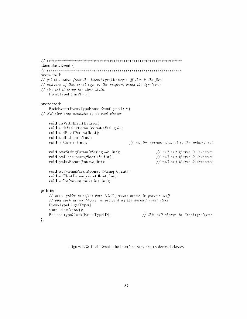
// �������������������������������������������������������������������class BasicEvent f// �������������������������������������������������������������������protected:
// get this value from the Event(Type)Manager i� this is the �rst// instance of this event type in the program using the typeName// else set it using the class static
EventTypeID myType;
protected:
BasicEvent(EventTypeName,EventTypeID &);
// NB ctor only available to derived classes
void dieWithError(EvError);
void addvStringParam(const vString &);
void addFloatParam( oat);
void addIntParam(int);
void setCurrent(int); // set the current element to the indexed val
void getvStringParam(vString �&, int); // will exit if type is incorrectvoid getFloatParam( oat �&, int); // will exit if type is incorrectvoid getIntParam(int �&, int); // will exit if type is incorrect
void setvStringParam(const vString &, int);
void setFloatParam(const oat, int);
void setIntParam(const int, int);
public:
// note: public interface does NOT provide access to params stu�// any such access MUST be provided by the derived event classEventTypeID getType();
char �className();
Boolean typeCheck(EventTypeID); // this will change to EventTypeNameg;
Figure B.3: BasicEvent: the interface provided to derived classes
87
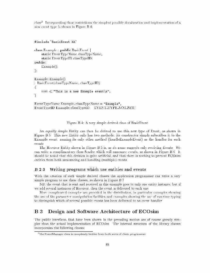
class3. Incorporating these restrictions the simplest possible decalaration and implementation of a
new event type is shown in Figure B.4:
#include "BasicEvent.hh"
class Example : public BasicEvent fstatic EventTypeName classTypeName;
static EventTypeID classTypeID;
public:
Example();
g;
Example::Example()
: BasicEvent(classTypeName, classTypeID)
fcout � "This is a new Example eventnn";
g
EventTypeName Example::classTypeName = "Example";
EventTypeID Example::classTypeID = EVENT TYPE NOT SET;
Figure B.4: A very simple derived class of BasicEvent
An equally simple Entity can then be derived to use this new type of Event, as shown in
Figure B.5. This new Entity only has two methods: its constructor simply subscribes it to the
Example event, naming its only other method (handleExampleEvent) as the handler for such
events.
The Receiver Entity shown in Figure B.5 is, as its name suggests only receiving Events. We
can write a complimentary class Sender which will announce events, as shown in Figure B.6. It
should be noted that this division is quite arti�cial, and that there is nothing to prevent ECOsim
entities from both announcing and handling (multiple) events.
B.2.3 Writing programs which use entities and events
With the creation of such simple derived classes the application programmer can write a very
simple program to use these classes, as shown in Figure B.7.
NB: the event that is sent and received in this example goes to only one entity instance, but if
we add several instances of Receiver, then the event is delivered to each one.
More complicated examples are provided in the distribution, in particular examples showing
the use of the parameter manipulation facilities and examples showing the use of run-time typing
to distinguish which of several possible events has been delivered to an event handler.
B.3 Design and Software Architecture of ECOsim
The public interfaces that have been shown in the preceding section are of course greatly sim-
pler than the actual implementation of ECOsim. The internal structure of the library classes
incorporates the following classes:
3the EventManager class is completely hidden from both sorts of client programmer
88

#include "Entity.hh"
class Receiver : public Entity fpublic:
Receiver();
void handleExampleEvent(BasicEvent &);
g;
Receiver::Receiver()
fSUBSCRIBE(Receiver,handleExampleEvent,"Example");
g
void Receiver::handleExampleEvent(BasicEvent &ev)
fcout � "Receiving an event of type " � ev.className() � "nn";
g
Figure B.5: Derived type of Entity, with one event-handler
class Conductor : public Entity fpublic:
Conductor();
void method();
g;
Conductor::Conductor()
f
g
void Conductor::method()
fExample myExample;
announce(myExample);
g
Figure B.6: Second derived type of Entity, which announces events
89
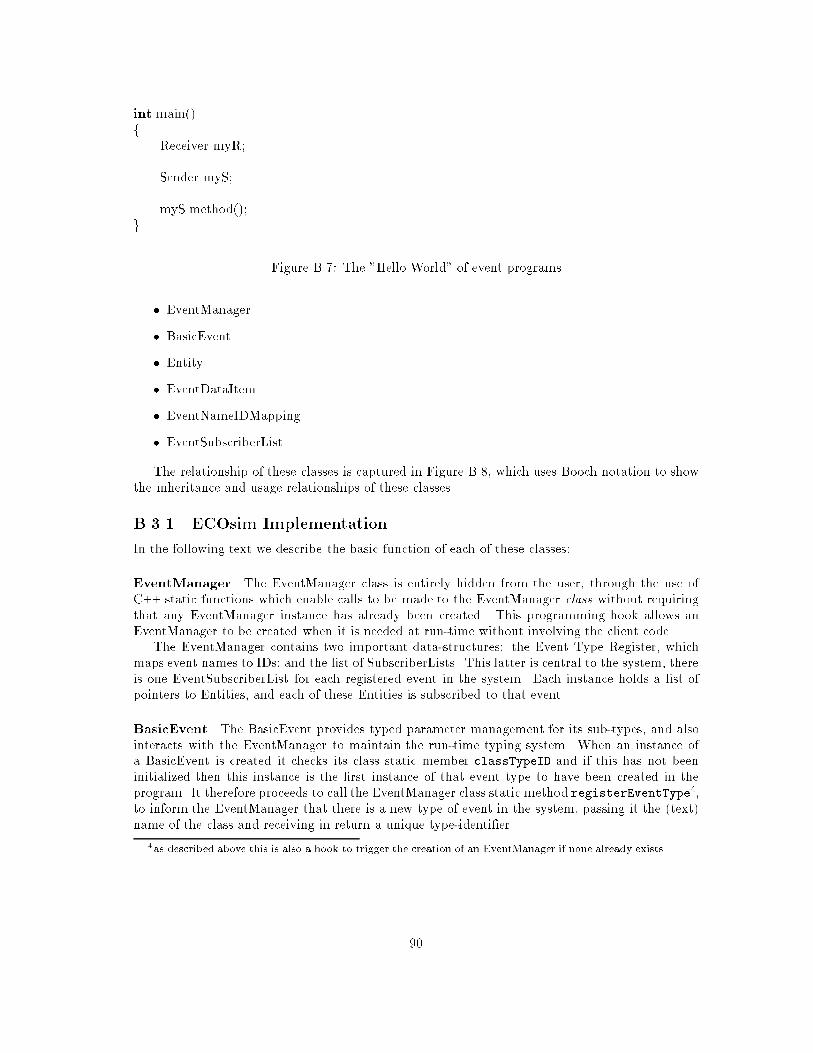
int main()
fReceiver myR;
Sender myS;
myS.method();
g
Figure B.7: The "Hello World" of event programs
� EventManager
� BasicEvent
� Entity
� EventDataItem
� EventNameIDMapping
� EventSubscriberList
The relationship of these classes is captured in Figure B.8, which uses Booch notation to show
the inheritance and usage relationships of these classes.
B.3.1 ECOsim Implementation
In the following text we describe the basic function of each of these classes:
EventManager The EventManager class is entirely hidden from the user, through the use of
C++ static functions which enable calls to be made to the EventManager class without requiring
that any EventManager instance has already been created. This programming hook allows an
EventManager to be created when it is needed at run-time without involving the client code.
The EventManager contains two important data-structures: the Event Type Register, which
maps event names to IDs; and the list of SubscriberLists. This latter is central to the system, there
is one EventSubscriberList for each registered event in the system. Each instance holds a list of
pointers to Entities, and each of these Entities is subscribed to that event.
BasicEvent The BasicEvent provides typed parameter management for its sub-types, and also
interacts with the EventManager to maintain the run-time typing system. When an instance of
a BasicEvent is created it checks its class static member classTypeID and if this has not been
initialized then this instance is the �rst instance of that event type to have been created in the
program. It therefore proceeds to call the EventManager class static method registerEventType4,
to inform the EventManager that there is a new type of event in the system, passing it the (text)
name of the class and receiving in return a unique type-identi�er.
4as described above this is also a hook to trigger the creation of an EventManager if none already exists
90

ECOsim and associated classes
BasicEvent
(from s)
AA
EventDataItem
(from s)
List<class EventDataIt
(from s)
Entity
(from s)
AA
EventTypeID
(from <unspecified>)EventTypeN
ame
(from <unspecified>)
Example
(from s.1)
Receiver
(from s.1)
Sender
(from s.1)
EventManager
(from s.1)
List<class EventNameI
(from s.1)
List<class EventSubscr
(from s.1)
current1 1
params
1
1
myType11
currentID
1
1
mapping
1
1
subscribeRegister
1
1
SS
classTypeName
1
1
SS
classTypeID
1
1
Figure
B.8:Booch
notatio
nfortheECOsim
libandsim
pleexample
91

Entity The Entity base class provides two important functions: �rstly, it provides the API for
subscription and announcement of events, and secondly it encapsulates all interaction between the
application and the EventManager.
As with BasicEvent, the �rst instance of an Entity must register with the EventManager5, but
in this case it is not for typing reasons, but simply to establish to which EventManager it is talking.
The subscription process has two parts. (telling the EventManager, storing the upcall pointer)
(handler invocation), (changing the subscribed method.
EventDataItem This simple class is used to maintain a mapping between a BasicEvent param-
eter and its type.
EventNameIDMapping This is a simple class to maintain a mapping between an event type
name and its ID.
EventSubscriberList As mentioned above there is one EventSubscriberList for each registered
event in the system. Each instance holds a list of pointers to Entities, and each of these Entities
is subscribed to that event. When an event of a given type is announced all the entities on the
appropriate list are given the event.
B.4 Future work
Despite its intended role as a short-term solution ECOsim has been written to be distributable
(for example, the parameter list management of BasicEvent is directly applicable to marshalling
for remote RPC communications), and is open to multi-threaded extension.
Any distributed version of ECOsim would probably use a derived class of EventManager, which
communicates with other EventManagers in other applications and on other machines. It would
also be feasible to derive sub-classes of BasicEvent, LocalEvent and GlobalEvent and to provide
explicit support in the EventManager for scoping using these classes.
To make ECOsim multi-threaded would involve insertion of some synchronisation code into the
base classes (in this case EventManager and Entity. Again, inheritance could be used here to
allow choice among several synchronisation policies for any given application speci�c Entities.
5As before, it must cause the creation of one if none has been created yet.
92

Appendix C
The ECO model: events +
constraints + objects
G. Starovic, V. Cahill, B. Tangney
Department of Computer Science, Trinity College Dublin
Abstract
This document describes the rationale and design of a programming model based on events,
constraints, and objects and the use of this model in the Moonlight1 project. It describes the
inter-object communication or invocation mechanism, and the way in which concurrency, synchro-
nisation, and timing properties are expressed and controlled. The invocation mechanism is unusual
in that it is event-based. It encourages loose coupling among the objects and this supports a high
degree of encapsulation for each object. Concurrency, synchronisation, and timing properties are
expressed in a uniform way using constraints which may be associated with objects and events. We
describe the way in which the abstractions of the ECO model are expressed at the language level,
and the support for them which is required from the runtime code and the underlying system.
C.1 Introduction
Large parallel and distributed applications are hard to program. Communication, synchronisation,
and timing contribute to the complexity of this task. Object-orientation is advertised as a good
paradigm for the modelling of entities in the application domain and a programming model which
allows more structured and less complex program development. The Moonlight project is building
an object-oriented environment for developing and executing games and virtual world applications.
Some of the requirements coming from such an environment are:
� support di�erent patterns of communication. As an example, a single object may collect
information from a number of sources or disseminate information to a number of destinations.
In general, there may be exchange of information between groups of objects, and the group
membership may change dynamically.
� support soft real-time applications. It must be possible to express timing constraints on
object behaviour. Such constraints arise out of the application domain and the way in which
audio and video data are handled. When the constraints are occasionally not satis�ed there
are no catastrophic consequences for the system or for its environment.
1This work is partially funded by the CEC under ESPRIT contract No. 8636
93

� support distributed and persistent applications. An application may span a number of nodes
in which case its objects communicate over a network. In some cases the objects will have
to be persistent, i.e., retain their state across separate executions.
� support large applications with thousands of objects, where new objects may be created and
the existing ones may disappear dynamically. This brings out the importance of issues like
scalability and scoping rules.
This document describes the rationale and design of the ECO programmingmodel and its use in
the Moonlight project2. It includes the inter-object communication or invocation mechanism, and
the way in which concurrency, synchronisation, and timing properties are expressed and controlled.
A number of other important issues, like persistence, grouping, and mobility of objects are not
considered in this document. The invocation mechanism is unusual in that it is event-based. It
encourages loose coupling among the objects which supports a high degree of encapsulation for
each object. Concurrency, synchronisation, and timing properties are expressed in a uniform way
using constraints which may be associated with objects and events. We describe the way in which
the abstractions of the ECO model are expressed at the language level, and the support for them
which is required from the runtime code and the underlying system.
The next section gives more details about objects with events and constraints and their possible
implementation. Section 3 gives several examples and section 4 surveys some related work and
compares it with the work reported in this document. The last section summarizes the main ideas,
describes the state of the present implementation and sets out future work.
C.2 Objects, events, and constraints
The basic abstractions of the ECO model are objects, classes, events, and constraints. In this
section we �rst brie y describe those properties of objects and classes which are relevant for the
description of events and constraints.
Objects communicate by announcing events and by processing those events which have been
announced. Each object is an instance of a class, it has instance variables and a number of methods
which operate on these variables. A class speci�es the interface to its instances (signatures of the
methods which may be invoked on the instances), together with the events and constraints used
by the instances. A method can be bound to one or more events in which case it behaves as an
event handler. It is invoked when the event is announced, and it can itself announce one or more
events. Several methods of an object can be bound to the same event. The type of an event
determines the number and types of its parameters. In order to bind a method to an event the
method signature has to match the event signature. The objects which announce an event are the
sources of the event. Each occurrence of an event can a�ect zero or more objects (can be delivered
to them causing invocations of their methods) | they are the destinations of the event. A source
announces events without having to worry about the identities or locations of the destinations.
Similarly, a destination object registers its interest in an event without having to worry about the
objects which may announce the event. If necessary, both naming and location information can
be expressed using event parameters.
Binding between a method and an event is dynamic. The method can stay bound to the event
from the moment its object is created until the object is deleted. Alternatively, the method is
bound at some arbitrary moment during the object lifetime and the binding can be changed after
that. In our present design events have global scope, and sources and destinations may be located
at di�erent nodes of the distributed system. We intend to introduce some form of scoping at a
2An earlier description of the same can be found in [13], which also describes other work on the Moonlight projectdone by the Distributed Systems Group at Trinity College Dublin. For more information on this project and workof all the partners involved contact [email protected].
94
later stage (possibly using the idea of spatial and temporal localities and area of interest managers
described in [40]).
A constraint speci�es a condition that should be either monitored-only or maintained and
monitored. It is de�ned over some domain, in our case the domain includes event parameters,
object instance variables, and possibly some constraint speci�c data. Constraints are evaluated
at the observable points (the start and end of an event handler). The scope of a constraint is
its enclosing class. There are di�erent kinds of constraints, categorized by the data which they
can access, by their evaluation points, and by the actions which they are allowed to perform.
The information used by the constraints depends on the application. There may be a library of
pre-de�ned constraints (e.g., those which implement typical synchronisation or timing constraints).
A program is a collection of cooperating objects, possibly placed on multiple nodes. When it
is started, one of its objects must subscribe to the special start event announced by the system
(a number of objects may subscribe to this event, i.e., there is not necessarily a single entry point
per program). An ECO implementation3 may automatically, or when instructed by the user, add
a handler for this event to one or more objects and allow the user to override this default handler.
The same can be done in some other cases, e.g., default handlers for special debugging events may
optionally be added to objects. Once the program is started the objects communicate with each
other by announcing events and by being noti�ed of event occurrences. They can also express their
interest, or lack of interest in speci�c events. The program may decide to end when it learns about
an occurrence of some event.
The ECO programmingmodel can be made available in di�erent existing languages. Two ways
in which this can be done are ([7]):
� extend an existing language by making the new abstractions visible or explicit, or
� add support for the new abstractions using the existing language mechanisms (e.g., by in-
heriting from library classes which support the new abstractions).
Which approach is chosen depends on a speci�c language and the required extensions. The
second approach may be easier to implement and easier to use (the original language remains
unchanged). However, if the extensions are of a fundamental nature (e.g., a new inter-object
communication mechanism, or a new form of inheritance), it may be di�cult or impossible to
integrate them seamlessly into an existing language. The �rst approach changes the language,
with all the consequences which this brings (lack of compatibility with the old language, the
extensions may not agree with the style of the original language). However, a language processor
used by the �rst approach provides more exibility, especially in the mentioned cases for which the
second approach is less suited. In this section we show a way in which C++ [54] is extended with
events and constraints.
C.2.1 Declaring events
Events have global scope and constraints have class scope. An event is de�ned with:
event EventName(parameters);
EventName is globally unique, and parameters is a list of event parameters (their names and types).
A class declares its in-events and out-events with:outevents list of EventNames;
inevents list of EventNames;
The former are those events which the instances of the class may announce, and the latter are
those which they may handle. In a way, they are similar to the import and export statements
in Modula-2 [61]. However, in-events and out-events di�er from these statements. in-events liststhose events in which the instances of the class may express interest at some moment during their
lifetime. out-events lists those events which the instances may announce to their environment.
3A compiler or language preprocessor.
95
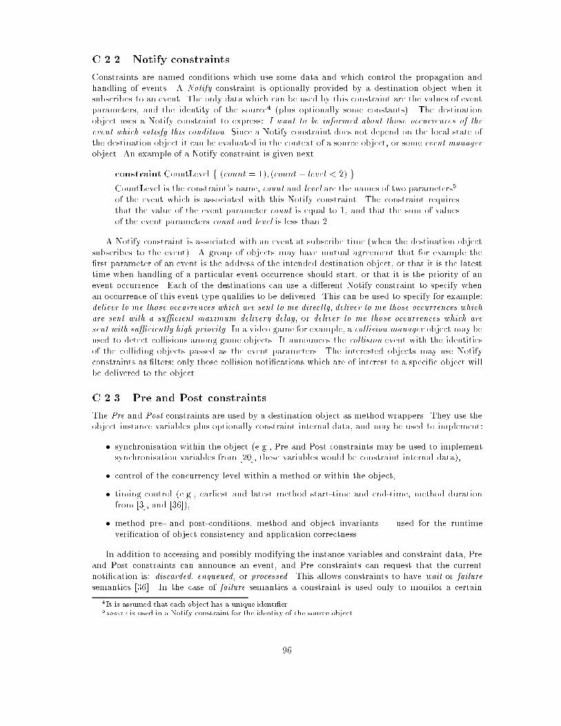
C.2.2 Notify constraints
Constraints are named conditions which use some data and which control the propagation and
handling of events. A Notify constraint is optionally provided by a destination object when it
subscribes to an event. The only data which can be used by this constraint are the values of event
parameters, and the identity of the source4 (plus optionally some constants). The destination
object uses a Notify constraint to express: I want to be informed about those occurrences of theevent which satisfy this condition. Since a Notify constraint does not depend on the local state of
the destination object it can be evaluated in the context of a source object, or some event managerobject. An example of a Notify constraint is given next.
constraint CountLevel f (count = 1); (count+ level < 2) g
CountLevel is the constraint's name, count and level are the names of two parameters5.
of the event which is associated with this Notify constraint. The constraint requires
that the value of the event parameter count is equal to 1, and that the sum of values
of the event parameters count and level is less than 2.
A Notify constraint is associated with an event at subscribe time (when the destination object
subscribes to the event). A group of objects may have mutual agreement that for example the
�rst parameter of an event is the address of the intended destination object, or that it is the latest
time when handling of a particular event occurrence should start, or that it is the priority of an
event occurrence. Each of the destinations can use a di�erent Notify constraint to specify when
an occurrence of this event type quali�es to be delivered. This can be used to specify for example:
deliver to me those occurrences which are sent to me directly, deliver to me those occurrences whichare sent with a su�cient maximum delivery delay, or deliver to me those occurrences which aresent with su�ciently high priority. In a video game for example, a collision manager object may be
used to detect collisions among game objects. It announces the collision event with the identities
of the colliding objects passed as the event parameters. The interested objects may use Notify
constraints as �lters; only those collision noti�cations which are of interest to a speci�c object will
be delivered to the object.
C.2.3 Pre and Post constraints
The Pre and Post constraints are used by a destination object as method wrappers. They use the
object instance variables plus optionally constraint internal data, and may be used to implement:
� synchronisation within the object (e.g., Pre and Post constraints may be used to implement
synchronisation variables from [20], these variables would be constraint internal data),
� control of the concurrency level within a method or within the object,
� timing control (e.g., earliest and latest method start-time and end-time, method duration
from [3], and [36]),
� method pre- and post-conditions, method and object invariants | used for the runtime
veri�cation of object consistency and application correctness.
In addition to accessing and possibly modifying the instance variables and constraint data, Pre
and Post constraints can announce an event, and Pre constraints can request that the current
noti�cation is: discarded, enqueued, or processed. This allows constraints to have wait or failuresemantics [36]. In the case of failure semantics a constraint is used only to monitor a certain
4It is assumed that each object has a unique identi�er.5source is used in a Notify constraint for the identity of the source object
96

condition (e.g., the values of some instance variables). When a noti�cation arrives and the pre-
condition is not satis�ed the constraint requests that the noti�cation be discarded, optionally
some event may be announced which will inform others about this failure. In the case of waitsemantics when a noti�cation arrives and it is found that the condition is not satis�ed the Pre
constraint may enqueue the noti�cation for later processing6. Conceptually, each Pre constraint
may have associated with it a queue of noti�cations. In order to allow the queued noti�cation to be
processed, a Pre or Post constraint may request dequeuing of a noti�cation from one of the queues
associated with the object's Pre constraints. When a noti�cation is dequeued its Pre constraint
will re-evaluate it, which may result in the noti�cation being discarded, processed, or enqueued
again. An example which shows how this works is given next.
A ResourceManager object manages some number of resources, and has one of its meth-
ods bound to the GetResource event and one of its methods bound to the FreeResource
event (these events are announced by other objects). A Pre constraint for the method
bound to GetResource can check if there are any available resources. If are none it
requests that the current event noti�cation is enqueued. A Post constraint for the
method bound to FreeResource requests that a noti�cation is dequeued from the queue
associated with the Pre constraint of the GetResource (if the queue is empty dequeuedoes nothing).
A Pre constraint may also request that a noti�cation is processed. This is done when it is found
that the condition is satis�ed and that the object can proceed with handling the noti�cation.
There are two options: process-active and process-passive which can be used to control the level
of concurrency within an object. If process-passive is requested there is a procedure call to the
event handler (the event parameters are passed to the handler, which may require that they are
unmarhsalled �rst if the noti�cation is received from a remote source). If process-active is requesteda new thread is created to execute the event handler (the event parameters are again passed to
the handler). Each of the discard, enqueue, process-passive and process-active) statements ends the
processing of the corresponding Pre constraint. Announcing an event and dequeuing noti�cations
does not end the current constraint.
The discard/enqueue/dequeue/process options available to the constraints place the responsibil-ity for implementing the synchronisation, timing, and other policies on the user. This mechanism
has some potential disadvantages:
� it may be regarded as too low-level. However, this may not be a problem since we expect that
there will be sets of frequently used constraints available to applications (e.g., constraints
which implement one-writer/multiple-readers access policy, or which implement some typical
timing constraints).
� The queueing of noti�cations may be too restrictive in some cases. There is a single queue
per method, and the enqueue and dequeue allow appending to the end of the queue and
removing from the front of the queue. Other possibilities (e.g., priority queues, various kinds
of searching through the queue) may be required by some constraints. However, the described
constraint options are intentionally left simple as it is expected that they will be su�cient
for a number of applications7. In other cases, constraints may be implemented by specialised
objects.
C.2.4 Announcing events and subscribing to events
An event is announced with:
6This will be done when it is believed that the same noti�cation may satisfy the condition at some later time,which may be the case for instance with synchronisation and timing constraints.
7If required, it would be easy to increase the expressive power of constraints with extensions like: allow speci�-cation of priority with enqueue and process-active; or allow ushing of a queue.
97

announce EventName(parameters)
The EventName must be on the out-event list of the object's class. The announcement is asyn-
chronous, the announcer does not wait for some \reply event" or for some object to handle the
event. A method can be bound to an event initially (when the object is created), and can change
its binding dynamically. The former is done in the class de�nition with:
MethodName(parameters) handles (EventName, NotifyName, PreName, PostName);
and the latter is done within the code with the subscribe and unsubscribe statements:
subscribeMethodName (EventName, NotifyName, PreName, PostName);
unsubscribeMethodName EventName;
in both cases the names of the constraints are optional. MethodName is local to the object which in-vokes subscribe/unsubscribe, and unsubscribe ushes the queue of the method/event Pre constraint.
It is expected that subscribe and unsubscribe will be used to express object's current interest in
certain events, while a Notify constraint will re�ne the speci�cation of an object's interest in a
speci�c event. It is possible to subscribe to or unsubscribe from a number of events. The following
shows an example of a class with events and constraints:
event E1(� � �);
event E2(� � �);
event E3(� � �);
class myclass f
inevents E1, E2;
outevents E3;
notify constraints
N f � � � g; // Notify constraint
pre constraints
C1 f � � � g; // Pre constraint
post constraints
C2 f � � � g; // Post constraint
methods
mymethod(� � �) handles (E1,N,C1,C2);
g
myclass::mymethod(� � �) f
announce E3(� � �);
unsubscribe mymethod E1;
subscribe mymethod (E2,,,);
g
In this example, the method �rst subscribes to E1 with some constraints, and then
(after announcing E3) it unsubscribes from E1, and subscribes to E2 without any
constraints.
98

C.2.5 Implementation
This subsection describes a way in which some of the above concepts may be implemented, other
implementations are possible.
Whenever an event de�nition is found in the code the event descriptor is registered in the
Event Register (event descriptors are persistent and shared by the applications). Each of the
events which appears on the in-events and out-events lists of a class must exist in the Event
Register. In addition to this, for each event the code for marshalling and unmarshalling of its
parameters has to be generated. At runtime, whenever an event is announced the information
related to this event occurrence is used to evaluate the Notify constraints associated with the
event. Event noti�cations are passed to the destinations of the satis�ed Notify constraints. At the
destination side, Pre and Post constraints are associated with methods, and support for discard,enqueue, dequeue, process-active, and process-passive is provided.
For the Notify constraints, there is code which will encode them and forward each of these
constraints to all the sources of a speci�c event. At the source side, there is code which maintains
the Notify constraints. The constraints are evaluated whenever their events are announced. An
event manager object (EM) may be implemented per object/per event, per object (for all its
events), per group of objects, or per node of the distributed system. One of the EM tasks can be
maintaining and evaluating all the Notify constraints of the object's out-events. All the objects
which can announce the same event can be registered as a group. If the underlying system supports
group communication it can be used to inform all the sources about changes in the bindings (a new
Notify constraint added, or an existing Notify constraint removed). When an object is created, or
when an existing object is brought into memory, it joins all the groups of its out-events. When an
object is deleted, or moved out of memory, it leaves all the groups of its out-events.Groups of event sources allow easier distribution of information about Notify constraints. In
a distributed system it may be desirable to evaluate the Notify constraints as near the sources
as possible, since this will stop the network tra�c of unwanted noti�cations. An alternative to
the groups of sources would be to use groups of destinations. This would make the distribution
of noti�cations easier, but the possible price is distributing a lot of unwanted noti�cations if
the Notify constraints are evaluated at the destination side. A third scenario which would have
both: (a) groups of sources and Notify constraints evaluated at the source side and (b) groups of
destinations, leaves open the question: \what criterion should be used to group the destinations".
The conditions under which a noti�cation is discarded by a Pre constraint application speci�c
and with multiple such constraints it seems less likely that they can be used to form groups of
destinations.
The use of the group communication mechanism described here is new. The usual way is to
have groups of processes or threads, in our case there are groups of objects (it may be groups
of EM objects). The only other reference that has groups of objects we know of is [31]. Also,
groups are usually used for fault-tolerance, but as stated in [31] they can be used \as an addressing
construct to accurately track a set of processes that share some characteristic". In our case we
track sets of objects and the shared characteristic of the objects in a group is their ability to
announce the same event. The group mechanism should be lightweight in order to cope with
a large number of potentially overlapping groups [60]. The underlying system has to support
lightweight threads and asynchronous communication (messages are used to communicate event
occurrences to remote nodes). The basic requirement, with respect to the reliability and ordering
properties of the underlying communication is: no guaranteed delivery and no guaranteed order.
Some applications may require more, e.g., a causal or total order of the event announcements,
subscribes, and unsubscribes.
99
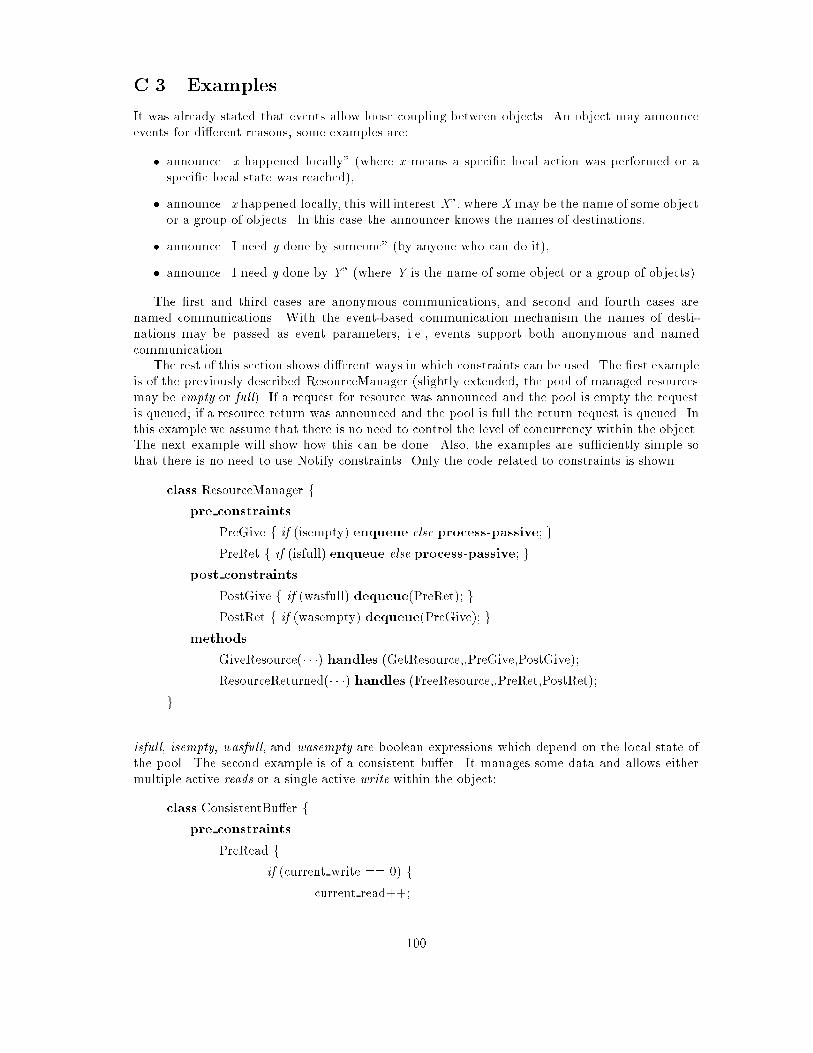
C.3 Examples
It was already stated that events allow loose coupling between objects. An object may announce
events for di�erent reasons, some examples are:
� announce \x happened locally" (where x means a speci�c local action was performed or a
speci�c local state was reached),
� announce \x happened locally, this will interest X", where X may be the name of some object
or a group of objects. In this case the announcer knows the names of destinations,
� announce \I need y done by someone" (by anyone who can do it),
� announce \I need y done by Y" (where Y is the name of some object or a group of objects).
The �rst and third cases are anonymous communications, and second and fourth cases are
named communications. With the event-based communication mechanism the names of desti-
nations may be passed as event parameters, i.e., events support both anonymous and named
communication.
The rest of this section shows di�erent ways in which constraints can be used. The �rst example
is of the previously described ResourceManager (slightly extended, the pool of managed resources
may be empty or full). If a request for resource was announced and the pool is empty the request
is queued; if a resource return was announced and the pool is full the return request is queued. In
this example we assume that there is no need to control the level of concurrency within the object.
The next example will show how this can be done. Also, the examples are su�ciently simple so
that there is no need to use Notify constraints. Only the code related to constraints is shown.
class ResourceManager f
pre constraints
PreGive f if (isempty) enqueue else process-passive; g
PreRet f if (isfull) enqueue else process-passive; g
post constraints
PostGive f if (wasfull) dequeue(PreRet); g
PostRet f if (wasempty) dequeue(PreGive); g
methods
GiveResource(� � �) handles (GetResource,,PreGive,PostGive);
ResourceReturned(� � �) handles (FreeResource,,PreRet,PostRet);
g
isfull, isempty, wasfull, and wasempty are boolean expressions which depend on the local state of
the pool. The second example is of a consistent bu�er. It manages some data and allows either
multiple active reads or a single active write within the object:
class ConsistentBu�er f
pre constraints
PreRead f
if (current write == 0) f
current read++;
100

process-active g
else enqueue; g
PreWrite f
if ((current read == 0) && (current write == 0)) f
current write++;
process-active g
else enqueue; g
post constraints
PostRead f
current read- -;
if (current read == 0) dequeue(PreWrite); g
PostWrite f
current write- -;
dequeue(PreWrite);
dequeue(PreRead); g
methods
Read(� � �) handles (ReadReq,,PreRead,PostRead);
Write(� � �) handles (WriteReq,,PreWrite,PostWrite);
g
Dequeuing of a noti�cation can be seen as causing an \internal object event". The code which
evaluates the object's constraints is sequential, and such \internal events" are processed before
processing of any external events is done. The level of concurrency is controlled at the observation
points, it is not possible for a constraint or method to suspend or abort a method of the same
object. Next, we describe the way in which some typical timing constraints can be implemented.
1. start after time and start before time requirements are implemented as Pre constraint. The
time may be received as an event parameter or speci�ed by the destination object. It may
be required to enqueue a noti�cation for later evaluation. In this case a timer event can be
used to trigger dequeuing of such noti�cations and re-evaluation of the Pre constraints.
2. �nish after time and �nish before time requirements are implemented as either Pre or Post
constraints. The time may again be received from the event announcer or speci�ed locally.
If the constraint is found to be unsatis�ed an event may be announced which will cause error
processing and possibly some recovery.
3. maximum duration time and minimum duration time are implemented with both Pre and
Post constraints. Otherwise, they are similar to the above timing constraints.
In addition to synchronisation, concurrency, and timing, constraints can be used to express method
pre-conditions, post-conditions, and invariants. Some of the ways in which they appear in other
languages are given next (p is a boolean expression over the object state):
� always p or invariant p,
� required p or when p,
� ensures p.
101

The �rst case is a method invariant and it is implemented with both Pre and Post constraints.
A method pre-condition (the second case) is implemented as a Pre constraint, and method post-
condition (the last case) as a Post constraint. In these examples, if a Pre constraint is not satis�ed
the event noti�cation is usually discarded (optionally some event may be announced). If a Post
constraint is not satis�ed it is usually accompanied by announcing some event.
C.4 Related work
A possibility of an event-based general-purpose communication mechanism has been suggested in
[45]. This ought to be seen in the context of other proposals for language and system support for
communication (where the communicating entities can be processes, threads, modules, or objects).
An early comparison of message passing and shared memory (or procedure-based) mechanisms
is reported in [38] and [50]. Some of the more recent related work can be found in [1], [9], [22], and
[60]. The remote procedure call (RPC) was introduced as a convenient extension of the procedure
call [47]. Its basic form is synchronous, two-way, and one-to-one exchange of messages ([11], [18]).
It encourages the client-server view of the world and in uences the way in which programs are
designed and implemented. The need for one-to-many, many-to-one, asynchronous, one-way, and
other forms of communication has led to the extensions of the basic RPC ([8], [24], [59], [62]), and
to completely di�erent approaches (e.g., [12], [14], [16], [21]).
An event based language for parallel programming called EBL is described by Reuveni [49]. In
this language events are the only control mechanism and cause the activation of event handlers.
Event occurrences can be permanent or temporary and events can be recurrent or non-recurrent.
Recurrent events can have multiple active occurrences, independently of whether they a�ect one
or more destinations, and non-recurrent events can have only one active occurrence at any time
(occurrences overwrite each other and only the last one survives).
The basic computational step is the announcement of an internal event (an event caused by the
program, external events are caused by hardware). EBL is not object-oriented, instead a program
consists of a collection of modules and each module consists of a number of event handlers. Events
are typed; each event type has a name. All the occurrences of the same type of event have the same
number and type of parameters (a parameter can be of an event type, in addition to simple types).
The only action possible in an event handler is the announcement of one or more events. Several
events can be announced sequentially or in parallel. A handler can be augmented with a condition
which has to be satis�ed before the handler is invoked. Reuveni also discusses the importance
of scoping of events, the ways of achieving synchronisation with events, and the expressiveness of
event based languages. Our work has been in uenced by [49] and can be seen as an attempt to
use some of these ideas in an environment which has objects and constraints.
The generative communication promoted by Linda [14] allows processes to communicate via the
tuple space. A sender inserts a tuple (a list of typed data �elds) into the space without having to
worry about the identity and locality of the receivers. Receivers can inspect or remove tuples from
this space by specifying a template tuple. The reception occurs when a match for the template
tuple is found. Communication through tuple space is used in [42] in the context of distributed
object-oriented languages. Oki et al. [48] use a variant of the Linda approach, called anonymouscommunication, where one �eld of each tuple is the subject �eld, and reception is based on the
matching of the subject �elds. Similar to the original approach, communication is independent of
the identities and locations of senders and receivers. Agha and Callsen [2] describe Actorspace, a
programming paradigm which integrates Actors [1] and Linda style communication. Actor-names
can be expressions, they are evaluated in order to �nd the actors whose names satisfy the given
expression. Actorspaces provide a scoping mechanism, are named and can form a hierarchy. The
control of the names visibility, as well as control of the scope lifetime, is explicit and dynamic. Our
approach has similar goals, but it is based on parameterized events and Notify constraints.
It is often stated that distributed systems require group communication, where the group mem-
102

bership changes and is determined by the global state of the computation (e.g., [2], [9]). Our work
is in line with the attempts to support multiple and changing communication patterns. The loose
coupling of objects avoids \the tendency of distributed naming systems to resolve names before
communication occurs" (Bayerdor�er [9]), and our constraint mechanism allows communications
to be speci�ed in terms of local object states. The associative broadcast primitive of [9] allows the
sender to provide an expression over attributes with each outgoing message. These expressions
are evaluated locally where the potential receivers reside and depending on the outcome of this
evaluation the messages are or are not delivered. Bayerdor�er considers events associated with
naming and communication. Our events can be associated with naming and communication, but
they can also be external events, timer events, and scheduling events [52].
Menon et al. [45] have thread-based and object-based event handlers. In ECO there are only
object-based handlers. They also mention several applications for which events are especially
suitable: distributed monitoring, debugging, and exception handling. The idea of loose coupling
among communicating entities (this time to ease the integration of software components) is also
used in [27] and [55]. There is insu�cient space here to compare various other ways in which events
are used (e.g., [23], [30], [37], [41], [51]).
Communication and control ow are often closely related | for instance communication primi-
tives can be blocking or non-blocking. Depending on where and under what conditions this blocking
is done it is possible to classify various primitives and languages with respect to their support for
concurrency and synchronisation control [6]. There has been much work on language support for
controlling the level of concurrency within objects and the order in which events occur. Arjomandi
et al. [7] overview various approaches to adding concurrency support to a programming language.
We use constraints to specify the level of concurrency within an object and do not make threads
visible (except through process-active and process-passive). Some of the work on synchronisation
constraints is reported in [10], [26], [43], and [58]. Frolund [26] have constraints speci�ed as part
of a class de�nition and each constraint restricts the set of methods which may be invoked when
an incoming request is received. A constraint may depend on the parameters of the received in-
vocation and the state of the target object8. Both [26] and [58] allow composition of constraints.
The former is concerned more with the permissive and the latter with the restrictive aspect of
constraints. In [26] each object has a controller which evaluates the constraints and may delay
invocations (event deliveries) if there is a chance that this will make them acceptable in future.
The Archie language [10] allows speci�cation of synchronisation states (or method pre-states),
and method post-states, and integrates these states with type information. It also addresses the
problem of multi-party synchronisation by introducing multioperations and coordinated calls based
on [8]. In our case, the constraint mechanism can be used to express the required order of event an-
nouncements and deliveries at the level of a single object. Multiparty synchronisation may require
complex expressions involving multiple events which we do not support at present. Our constraints
allow the implementation of activation conditions [20], which are based on synchronisation counters[5]. An activation condition is attached to a method, and can depend on the instance variables,
names of the methods, invocation parameters, and synchronisation counters. The counters are the
object instance data maintained by the system and showing for instance the number of times each
method was started, �nished, or started and not �nished.
The timing behaviour of a system is naturally described with constraints on event occurrences
([4], [19], [34]). Language support for expressing these constraints helps the development of pro-
grams which meet their timing speci�cation [29]. Kenny and Lin [36] state that for a real-time
system \there must be a way to de�ne the constraints on time and resources to the computations.
Some notion of a constraintmust therefore be part of the system". Their language (Flex) has a con-
straint mechanism as a basic programming primitive. Flex constraints are associated with blocks
of code. Exception handlers may be provided and will be executed when some of the constraints
fail. An important concept used by various real-time languages is that of observable points [29].
8Frolund mentions the possibility of using \history instance variables" in the constraints.
103
They can be seen as markers, relevant for evaluating constraints, for making scheduling decisions
and for tuning the code. Di�erent languages have di�erent notions of observable points. In our
case, the observable points are at the object level (start and end of an event handler); in Flex they
are at the level of a block of code.
The authors of [3] and [33] describe di�erent ways of expressing timing constraints and inte-
grating them into an object-oriented language. Timing behaviour can be described by specifying
the minimum and maximum time when a certain observation point in the code is reached, or by
specifying the time interval between two observation points. RTC++ [33] allows timing constraints
both at the operation and statement level. It also allows a non-timing constraint to be speci�ed
for an operation, which can depend on the instance variables and message parameters. A func-
tion may be provided which is invoked when a constraint is not satis�ed, and which will decide
whether or not the invocation should be queued. The approach described in [3] relies on real-time
composition �lters for expressing timing constraints. There are input and output �lters, speci�ed
at the class level. When an invocation message is received it is matched against the input �lters
for the class. The matching consists of evaluating a named expression which can depend on both
instance and external variables. The method names can also be used for matching | a �lter can
be shared by several methods of an object. When a match is found the timing constraint from the
corresponding �lter is used. Our approach is similar but simpler (it has fewer basic abstractions)
and more general.
Events and constraints have been used for constructing active databases with their Event-
Condition-Action programming model (e.g., [15], [28]). Gehani et al. [28] support events and
triggers in a database programming language. The events are of interest to one object or of
interest to a group of objects and can be:
� basic events There is a number of prede�ned basic events, e.g., creation or deletion of an
object, invocation of a member function, time-related and transaction-related events. A
member function (its signature) can be used as a part of an event declaration.
� logical events They are the basic events optionally associated with masks. A mask is a pred-
icate which speci�es which occurrences of an event are of interest. It can use the parameters
of the event being masked, or it can use the state of an object.
� composite events, logical composite events A composite event combines several logical events
using the logical operators (and, or, not) and special event operators. The latter allow among
other things speci�cation of event order and periodic events.
The work reported in [28] is similar to our work in some ways. One important di�erence is that in
our case events are used as a general communication mechanism. Also, we do not have composite
events, but they can be supported at a higher level. A mask is similar to our constraint, but
the latter cannot depend on the state of arbitrary objects. In [28] events are local to an object,
and triggers are associated with a class de�nition. A trigger links an event with an action, and
is active either perpetually or until the associated event is observed and the action is �red. The
trigger corresponds to our facility to subscribe/unsubscribe to an event (both serve to link an
event, constraint, and action). In [28] an action can be an arbitrary statement block while in our
case an action is an event handler which is a method of some object.
In addition to being used for concurrency, synchronisation, and timing, constraints are used for
specifying object invariants ([46]), and as a general construct in declarative languages (e.g., [25]).
C.5 Conclusions, present state and future work
This document describes the ECO programming model and its use in the Moonlight project. The
event-based mechanism is used for communication among objects, it allows a higher degree of en-
capsulation and simpli�es development of large and complex applications. A generalised constraint
104

mechanism allows speci�cation of a number of di�erent requirements (synchronisation and concur-
rency within an object, timing behaviour of an object, and object's invariants). Although events
and constraints have been used elsewhere, this combination of events, constraints, and objects
allows a new and often more natural style of programming. Since events diminish the importance
of object references they may allow new approaches to persistence and garbage collection.
At present, we are implementing the support for the ECO model in a single address space,
which is the �rst requirement in the Moonlight project. In addition, the project aims at providing
a set of tools which will help the user to create new games and virtual world applications. In such
an environment, as already mentioned, there are a number of additional issues which will have to
be resolved. One of them is scoping of events. Another is the required kind of inheritance. It
is known that inheritance may interfere with synchronisation and timing constraints ([43], [26],
[3]). In our case, constraints allow separation of the synchronisation and timing code from the
\ordinary" application code. A library of typical constraints may be provided. It remains to be
determined whether, in such an environment, there is a need for inheriting constraints and if there
is then how it should be done. More important than this is to provide some support for expressing
complex constraints which involve multiple events and multiple objects9. It may be possible to do
this at a higher level using the basic building blocks described here.
Acknowledgements
The following people contributed with their comments and in other ways to the work reported
here: A. Condon, A. Donnelly, N. Harris, S. McGerty, C. McHale, K. O'Connell, P. Taylor (Trinity
College Dublin), D. Belsnes, B. Hauksson, A. Lie (Norsk Regnesentral Oslo), P. Caselles, L. del
Pino (APD S.A. Madrid).
9A simple example of this is synchronous communication which involves ordered request and reply events, and
may involve two or more objects.
105
Bibliography
[1] G. Agha. Actors: A model of concurrent computation in distributed systems. MIT Press, 1986.
[2] G. Agha and C.J. Callsen. Actorspaces: A model for scalable heterogenous computing. Techni-
cal Report UIUCDCS-R-92-1766 and UILU-ENG-92-1746, Department of Computer Science,
University of Illinois at Urbana-Champaign, November 1992.
[3] M. Aksit, J. Bosch, W. van der Sterren, and L. Bergmans. Real-time speci�cation inheritance
anomalies and real-time �lters. In ECOOP, pages 386{407, July 1994.
[4] T. Amon. Speci�cation, simulation, and veri�cation of timing behaviour. PhD thesis, 1993.
[5] F. Andre, D. Herman, and J.P. Verjus. Synchronisation of Parallel Programs. North Oxford
Academic, Oxford, 1985.
[6] G.R. Andrews and F.B. Schneider. Concepts and notations for concurrent programming.ACMComputing Surveys, 115(1):3{43, March 1983.
[7] E. Arjomandi, W. O'Farrell, and I. Kalas. Concurrency support for C++: an overview.
Technical Report CS-93-03, York University, Canada, August 1993.
[8] J-P. Banatre, M. Banatre, and F. Ployette. The concept of Multi-function: a general struc-
turing tool for distributed operating system. In Proc. of the 6th IEEE Distributed ComputingConference, pages 478{485, 1986.
[9] B.C. Bayerdor�er. Associative Broadcast and the Communication Semantics of Naming inConcurrent Systems. PhD thesis, The University of Texas at Austin, December 1993.
[10] M. Benveniste and V. Issarny. Concurrent programming notations in the object-oriented
language Archie. Technical Report 1882, INRIA-Rennes, December 1992.
[11] A.D. Birell and B.J. Nelson. Implementing remote procedure calls. ACM Transactions onComputer Systems, 2(1):39{59, February 1984.
[12] K. Birman and R. Van Renesse. Reliable Distributed Computing using the ISIS toolkit. IEEEPress, 1993.
[13] V. Cahill, A. Condon, G. Starovic, and B. Tangney. Moonlight: VOID shell and execution
environment de�nition. Deliverable 1.2.1. and 1.3.1, September 1994.
[14] N. Carriero and D. Gelernter. Linda in context. Communications of the ACM, 32(4):444{458,
April 1989.
[15] S. Chakravarthy and D. Mishra. Snoop: an expressive event speci�cation language for ac-
tive databases. Technical Report UF-CIS-TR-93-007, University of Florida, Computer and
Information Sciences, March 1993.
106

[16] A.T. Chandramohan, H.M. Levy, and E.D. Lazowska. Separating data and control transfer in
distributed operating systems. Technical Report 94-07-04, Department of Computer Science
and Engineering, University of Washington, July 1994.
[17] Andrew Condon. Video game development using void. Technical Report DSG-MOONLIGHT-
15, Distributed Systems Group, Trinity College Dublin, 1994.
[18] J.R. Corbin. The art of distributed applications. Programming techniques for remote procedurecalls. 1991.
[19] B. Dascarathy. Timing constraints of real-time systems: constructs for expressing them,
methods of validating them. SE-11(1):80{86, January 1985.
[20] D. Decouchant, S. Krakowiak, M. Meysembourg, M. Riveill, and X.R. de Pina. A synchro-
nisation mechanism for typed objects in a distributed system. In OOPSLA, pages 105{107,1988.
[21] C.A. DellaFera, M.W. Eichin, R.S. French, D.C. Jedlinsky, J.T. Kohl, and W.E. Sommerfeld.
The Zephyr noti�cation service. In USENIX, Dallas, Texas, February 1988.
[22] M. Diaz, C. Chassot, A. Lozes, and K. Drira. On the space of multimedia connections. In
Cabernet Workshop, Trinity College Dublin, January 1994.
[23] M. Donner, D. Jameson, and W. Moran. Events: a structuring mechanism for a real-time
runtime system. In Proc. of the Real-Time Systems Symposium, pages 22{30, December 1989.
[24] N. Francez. Cooperating proofs for distributed programs with multiparty interactions. Infor-mation Processing Letters, 32:235{242, September 1989.
[25] B.N. Freeman-Benson and A. Borning. Integrating constraints with an object oriented lan-
guage. In ECOOP, pages 268{286, June 1992.
[26] S. Frolund. Inheritance of synchronisation constraints in concurrent object oriented program-
ming. In ECOOP, pages 185{196, June 1992.
[27] D. Garlan and D. Notkin. Formalising design spaces: implicit invocation mechanism. In
Lecture Notes in Computer Science 551: VDM Formal Software Development Methods, pages31{44, 1991.
[28] N.H. Gehani, H.V. Jagadish, and O. Shmueli. Event speci�cation in an active object-oriented
database. In Proc. of the ACM SIGMOD International Conference on Management of Data,pages 81{90, San Diego, California, June 1992.
[29] R. Gerber and S. Hong. Semantics-based compiler transformations for enhanced schedulabil-
ity. In Proceedings of IEEE Real-Time Systems Symposium, pages 232{242. IEEE Computer
Society Press, December 1993.
[30] Object Management Group. Object services architecture, August 1992.
[31] O. Hagsand, H. Herzog, K. Birman, and R. Cooper. Object-oriented reliable distributed
computing. In I-WOOS, 1992.
[32] David Harel. Statecharts: a visual formalism for complex systems.
[33] Y. Ishikawa, H. Tokuda, and C.W. Mercer. Object-oriented real-time language design: con-
structs for timing constraints. In ECOOP/OOPSLA, pages 289{298, October 1990.
107

[34] F. Jahanian, R. Rajkumar, and S. Raju. Runtime monitoring of timing constraints in dis-
tributed real-time systems. Technical Report CSE-TR 212-94, University of Michigan, April
1994.
[35] Kevin Jameson. Multi-Platform Code Management. O'Reilly & Associates, 94.
[36] K.B. Kenny and K. Lin. Building exible real-time systems using the Flex language. IEEEComputer, 24(5):70{78, May 1991.
[37] T. Larrabee and C.L. Mitchell. Gambit: a prototyping approach to video game design. IEEESoftware, 1(4):28{36, October 1984.
[38] H.C. Lauer and R.M. Needham. On the duality of operating systems structures. ACMOperating Systems Review, 13(2):3{19, April 1979.
[39] Paul Jay Lucas. An object-oriented language system for implementing concurrent, hierarchical,
�nite state machines. Technical report, University of Illinois at Urbana-Champaign, 93.
[40] M.R. Macedonia, M.J. Zyda, D.R. Pratt, P.T. Barham, and S. Zeswitz. Npsnet: A network
software architecture for large scale virtual environments. Presence, 3(4), 1994.
[41] N. Mans�eld. X Window System. A user's guide. 1991.
[42] S. Matsuoka and S. Kawai. Using tuple space communication in distributed object-oriented
languages. SIGPLAN Notices, 23(11):276{284, 1988.
[43] S. Matsuoka and K. Wakita. Synchronisation constraints with inheritance: what is not possible
| so what is? Technical Report 90-010, Department of Information Science, The University
of Tokyo, 1990.
[44] Ciaran McHale. Synchronisation in Concurrent, Object-oriented Languages: ExpressivePower, Genericity and Inheritance. PhD thesis, Department of Computer Science, Trinity
College, Dublin 2, Ireland, October 1994.
[45] S. Menon, P. Dasgupta, and R.J. LeBlanc. Asynchronous event handling in distributed object-
based systems. In Proc. the 13th Conference on Distributed Computing Systems, pages 383{390, Pittsburgh, Pennsylvania, May 1993.
[46] B. Meyer. Ei�el: The Language. Prentice Hall, Englewood Cli�s, New Jersey, 1992.
[47] B.J. Nelson. Remote Procedure Call. PhD thesis, 1981.
[48] B. Oki, M. P uegl, A. Siegel, and D. Skeen. The Information Bus - an architecture for
extensible distributed systems. In ACM Symposium on Principles of Operating Systems,pages 58{68, 1993.
[49] A. Reuveni. The Event Based Language and its Multiple Processor Implementations. PhD
thesis, 1980.
[50] M.L. Scott. Messages vs. remote procedures is a false dichotomy. SIGPLAN Noticies, 18(3):57{62, May 1983.
[51] Y-P. Shan. An event driven Model-View-Controller framework for Smalltalk. In OOPSLA,pages 347{352, October 1989.
[52] G. Starovic. Scheduling and communication with events (unpublished internal document),
June 1994.
108

[53] G. Starovic, V. Cahill, and B. Tangney. The ECO model: events + constraints + objects,
February 1995. Submitted to the Usenix Conference on Object-Oriented Technologies 95.
[54] B. Stroustrup. The C++ Programming Language. 2nd edition. Addison-Wesley, 1991.
[55] K.J. Sullivan and D. Notkin. Reconciling environment integration and software evolution.
1(3):229{268, July 1992.
[56] Gradimir Starovic & Vinny Cahill & Andrew Condon & Stephen McGerty & Karl O'Connell
& Gradimir Starovic & Brendan Tangney. The eco model: Events + constraints + objects.
Technical report, Distributed Systems Group, Trinity College Dublin, 95.
[57] Vinny Cahill & Andrew Condon & Gradimir Starovic & Brendan Tangney. Void shell and
execution environment de�nition. Technical report, TCD, 94.
[58] C. Tomlinson and V. Singh. Inheritance and synchronisation with enabled-sets. In OOPSLA,pages 103{111, October 1989.
[59] USL. Tuxedo system, release 4.2 manual, 1992.
[60] R. van Renesse, T.M. Hickey, and K.P. Birman. Design and performance of Horus: a
lightweight group communication system. Technical Report 94-1442, Department of Com-
puter Science, Cornell University, August 1994.
[61] N. Wirth. Programming in Modula-2. Springer-Verlag, 1982.
[62] M.D. Wood. Replicated RPC using Amoeba closed group communication. In Proc. of the13th Conf. on Distributed Computing Systems, pages 499{507, May 1993.
109