concentrating collectors - power generation -...
TRANSCRIPT
Sustainable Energy Science and Engineering Center
Concentrating Collectors -
Power Generation
Sustainable Energy Science and Engineering Center
Concentrating Collectors
Collectors are oriented to track the sun so that the beam radiation will be directed onto the absorbing surface
Collector: Receiver and the concentrator
Receiver: Radiation is absorbed and converted to some other energy form (e.g. heat).
Concentrator: Collector that directs radiation onto the receiver. The aperture of the concentrator is the opening through which the solar radiation enters the concentrator
Source: Chapter 7 of Solar Engineering of thermal processes by Duffie & Beckman, Wiley, 1991
Reference: http://www.powerfromthesun.net/book.htm
Sustainable Energy Science and Engineering Center
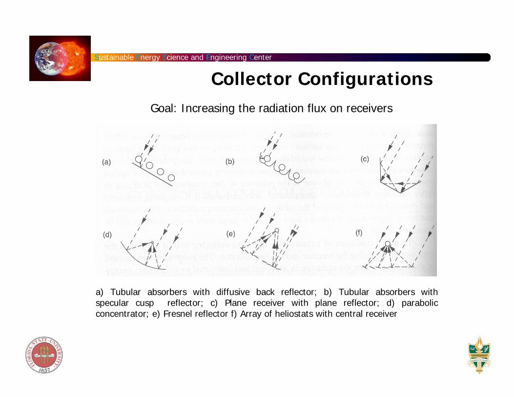
a) Tubular absorbers with diffusive back reflector; b) Tubular absorbers with specular cusp reflector; c) Plane receiver with plane reflector; d) parabolic concentrator; e) Fresnel reflector f) Array of heliostats with central receiver
Collector ConfigurationsGoal: Increasing the radiation flux on receivers
Sustainable Energy Science and Engineering Center
Concentrating Collectors
Fresnel Lens: An optical device for concentrating light that is made of concentric rings that are faced at different angles so that light falling on any ring is focused to the same point.
Parabolic trough collector: A high-temperature (above 360K) solar thermal concentrator with the capacity for tracking the sun using one axis of rotation. It uses a trough covered with a highly reflective surface to focus sunlight onto a linear absorber containing a working fluid that can be used for medium temperature space or process heat or to operate a steam turbine for power or electricity generation.
Central Receiver: Also known as a power tower, a solar power facility that uses a field of two-axis tracking mirrors known as heliostat (A device that tracks the movement of the sun). Each heliostat is individually positioned by a computer control system to reflect the sun's rays to a tower-mounted thermal receiver. The effect of many heliostats reflecting to a common point creates the combined energy of thousands of suns, which produces high-temperature thermal energy. In the receiver, molten nitrate salts absorb the heat energy. The hot salt is then used to boil water to steam, which is sent to a conventional steam turbine-generator to produce electricity.
Sustainable Energy Science and Engineering Center
Concentration Types
Planar and non-concentrating type which provides concentration ratios of up to four and are of the flat plate type.
Line focusing type produces a high density of radiation on a line at the focus. Cylindrical parabolic concentrators are of this type and they could produce concentration ratios of up to ten.
Point focusing type generally produce much higher density of radiation in the vicinity of a point. Paraboloids are examples of point focus concentrators.
Sustainable Energy Science and Engineering Center
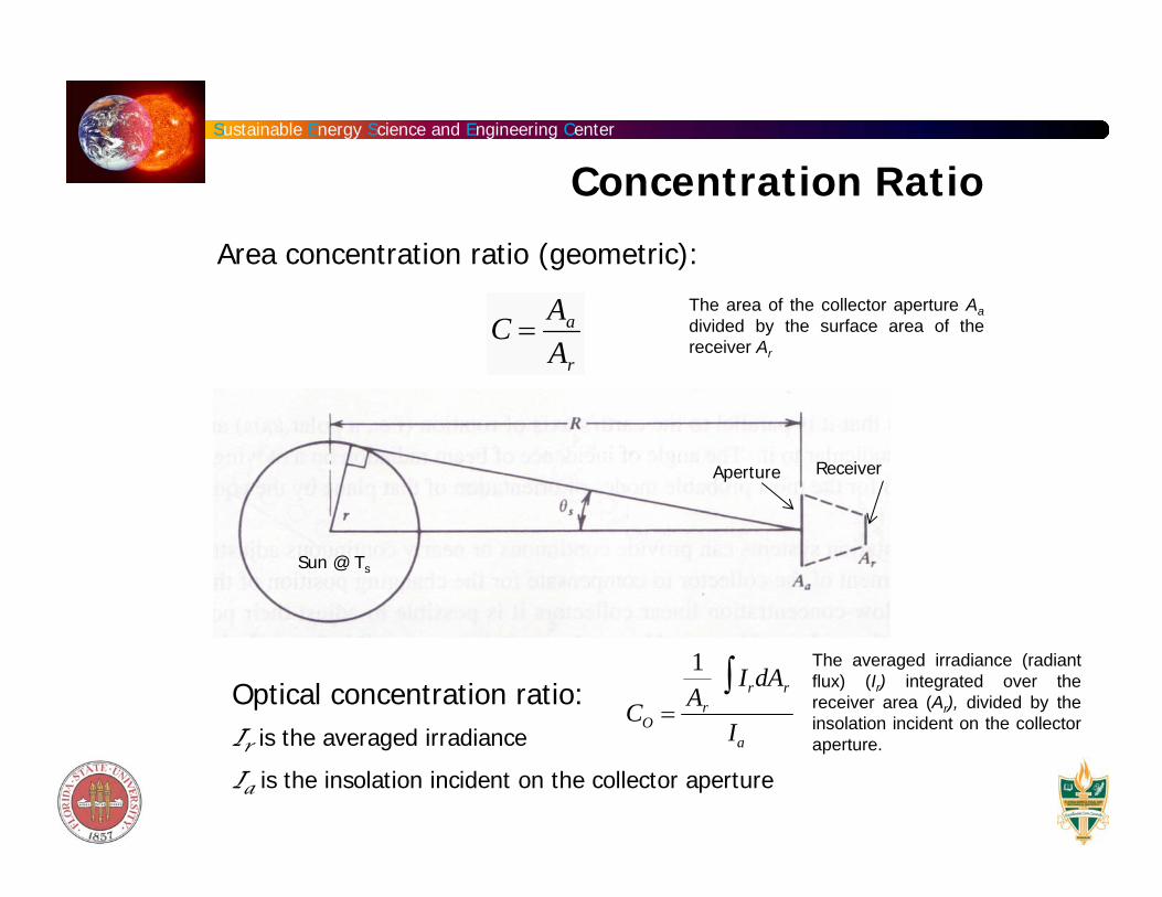
Area concentration ratio (geometric):
Concentration Ratio
C =Aa
Ar
Sun
Optical concentration ratio:Ir is the averaged irradiance
Ia is the insolation incident on the collector aperture
CO =
1Ar
IrdAr∫Ia
Aperture Receiver
Sun @ Ts
The averaged irradiance (radiant flux) (Ir) integrated over the receiver area (Ar), divided by the insolation incident on the collector aperture.
The area of the collector aperture Aadivided by the surface area of the receiver Ar
Sustainable Energy Science and Engineering Center
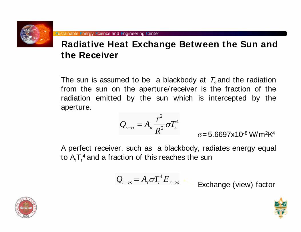
The sun is assumed to be a blackbody at Ts and the radiation from the sun on the aperture/receiver is the fraction of the radiation emitted by the sun which is intercepted by the aperture.
σ=5.6697x10⁻⁸ W/m2K4
A perfect receiver, such as a blackbody, radiates energy equal to ArTr
4 and a fraction of this reaches the sun
Exchange (view) factor
Qs→r = Aar2
R2 σTs4
Qr→s = ArσTr4 Er→s
Radiative Heat Exchange Between the Sun and the Receiver
Sustainable Energy Science and Engineering Center
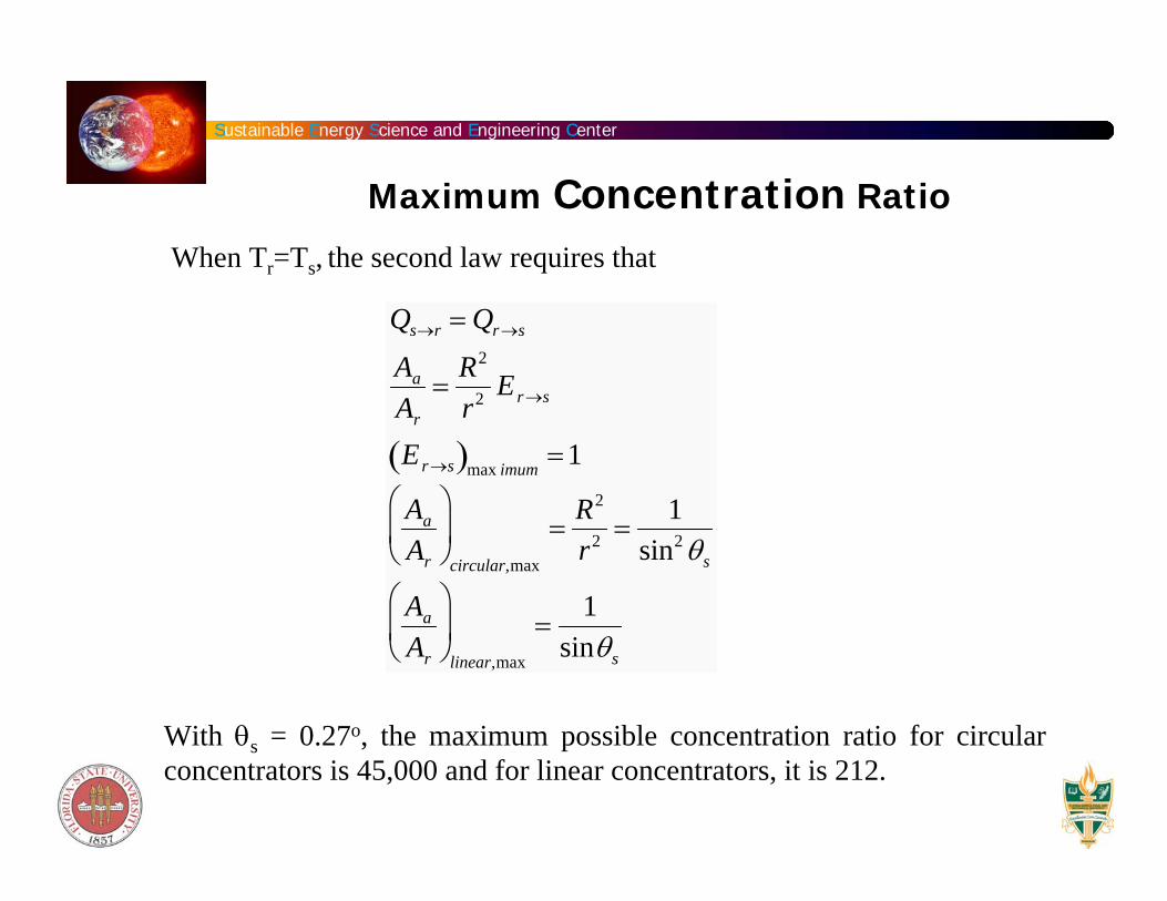
When Tr=Ts, the second law requires that
With θs = 0.27o, the maximum possible concentration ratio for circular concentrators is 45,000 and for linear concentrators, it is 212.
Maximum Concentration Ratio
Qs→r = Qr→s
Aa
Ar
=R2
r2 Er→s
Er→s( )max imum =1
Aa
Ar
⎛
⎝ ⎜
⎞
⎠ ⎟
circular,max
=R2
r2 =1
sin2 θs
Aa
Ar
⎛
⎝ ⎜
⎞
⎠ ⎟
linear,max
=1
sinθs
Sustainable Energy Science and Engineering Center
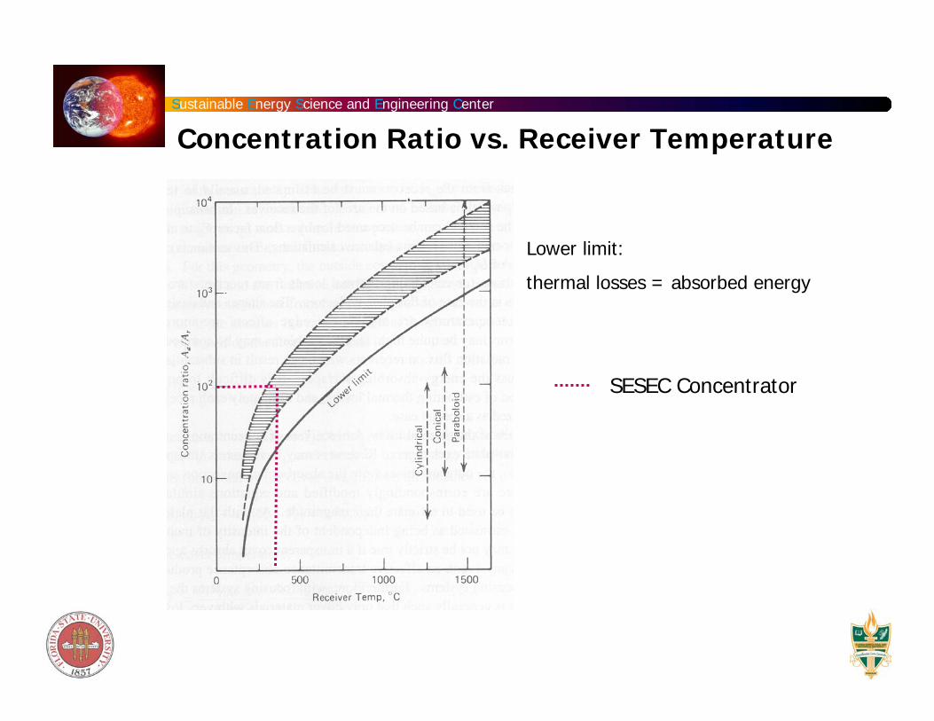
Lower limit:
thermal losses = absorbed energy
Concentration Ratio vs. Receiver Temperature
SESEC Concentrator
Sustainable Energy Science and Engineering Center
Thermal Performance
Ý Q out = Ý Q opt − Ý Q loss
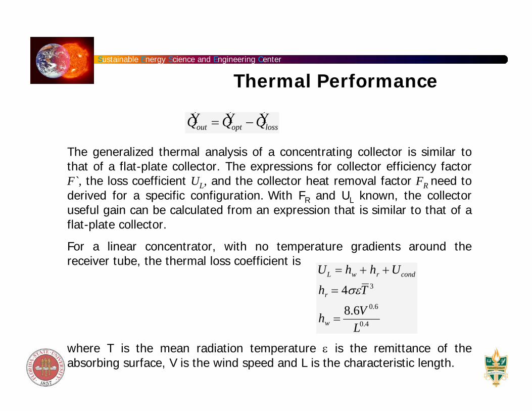
The generalized thermal analysis of a concentrating collector is similar to that of a flat-plate collector. The expressions for collector efficiency factorF`, the loss coefficient UL, and the collector heat removal factor FR need to derived for a specific configuration. With FR and UL known, the collector useful gain can be calculated from an expression that is similar to that of a flat-plate collector.
For a linear concentrator, with no temperature gradients around the receiver tube, the thermal loss coefficient is
where T is the mean radiation temperature ε is the remittance of the absorbing surface, V is the wind speed and L is the characteristic length.
UL = hw + hr + Ucond
hr = 4σεT 3
hw =8.6V 0.6
L0.4
Sustainable Energy Science and Engineering Center
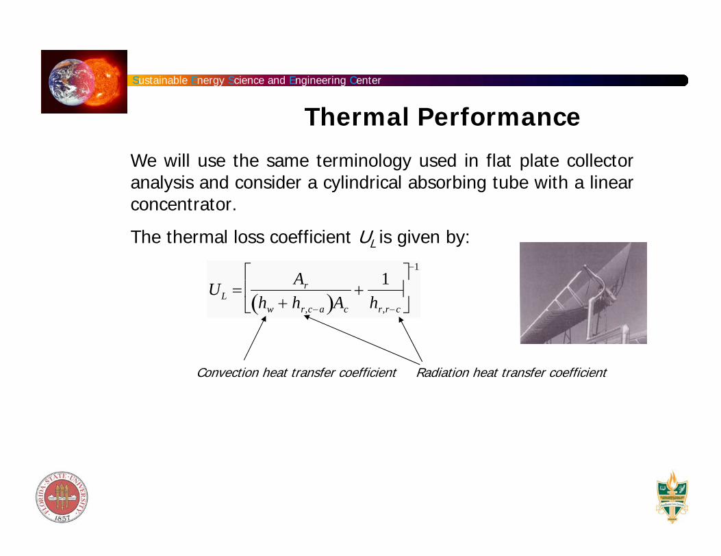
We will use the same terminology used in flat plate collector analysis and consider a cylindrical absorbing tube with a linearconcentrator.
The thermal loss coefficient UL is given by:
Convection heat transfer coefficient Radiation heat transfer coefficient
Thermal Performance
UL =Ar
hw + hr,c−a( )Ac
+1
hr,r−c
⎡
⎣ ⎢
⎤
⎦ ⎥
−1
Sustainable Energy Science and Engineering Center
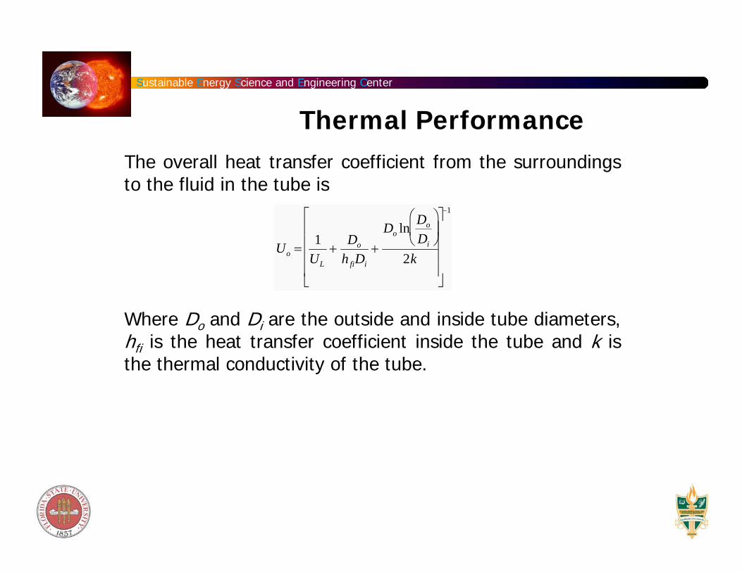
The overall heat transfer coefficient from the surroundings to the fluid in the tube is
Where Do and Di are the outside and inside tube diameters, hfi is the heat transfer coefficient inside the tube and k is the thermal conductivity of the tube.
Uo =1
UL
+Do
h fiDi
+Do ln Do
Di
⎛
⎝ ⎜
⎞
⎠ ⎟
2k
⎡
⎣
⎢ ⎢ ⎢ ⎢
⎤
⎦
⎥ ⎥ ⎥ ⎥
−1
Thermal Performance
Sustainable Energy Science and Engineering Center
The useful energy gain per unit of collector length:
Where Aa is the unshaded area of the concentrator aperture and Ar is the area of the receiver (πDoL for a cylindrical absorber), S is the absorbed solar radiation per unit of aperture area, Tf is the local fluid temperature and F’ is the collector efficiency factor given by Uo/UL.
′ q u = F ' Aa
LS −
Ar
Aa
UL Tf − Ta( )⎡
⎣ ⎢
⎤
⎦ ⎥
Thermal Performance
Sustainable Energy Science and Engineering Center
The actual useful energy gain:
Where Aa is the unshaded area of the concentrator aperture and Ar is the area of the receiver, S is the absorbed solar radiation per unit of aperture area, Ti is the inlet fluid temperature and FR is the collector heat removal factor.
Qu = FR Aa S −Ar
Aa
UL Ti − Ta( )⎡
⎣ ⎢
⎤
⎦ ⎥
FR =Ý m Cp
AcUL
1− exp −ACULF '
Ý m Cp
⎛
⎝ ⎜ ⎜
⎞
⎠ ⎟ ⎟
⎡
⎣ ⎢ ⎢
⎤
⎦ ⎥ ⎥
Thermal Performance
Sustainable Energy Science and Engineering Center
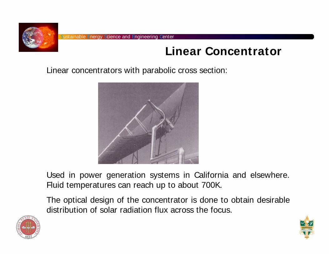
Linear concentrators with parabolic cross section:
Used in power generation systems in California and elsewhere. Fluid temperatures can reach up to about 700K.
The optical design of the concentrator is done to obtain desirable distribution of solar radiation flux across the focus.
Linear Concentrator
Sustainable Energy Science and Engineering Center
The absorbed radiation per unit area of unshaded aperture is given by:
Where Ib is effective incident beam radiation on the plane of the aperture, ρ is the specular reflectance of the concentrator, γ (the intercept factor), τ (the transmittance), and α (the absorptance) are functions of the angle of incidence of radiation on the aperture. Kγτα is an incidence angle modifier that can be used to account for deviations from the normal of the angle of incidence of the radiation on the aperture.
The intercept factor is defined as the fraction of the reflectedradiation that is incident on the absorbing surface of the receiver.
S = Ibρ γτα( )n Kγτα
Linear Concentrator
γ =I(y)dy
A
B
∫
I(y)dy−∞
∞
∫Receiver extends from A to B
Sustainable Energy Science and Engineering Center
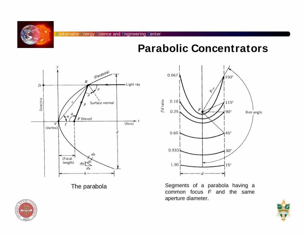
The parabola Segments of a parabola having a common focus F and the same aperture diameter.
Parabolic Concentrators
Sustainable Energy Science and Engineering Center
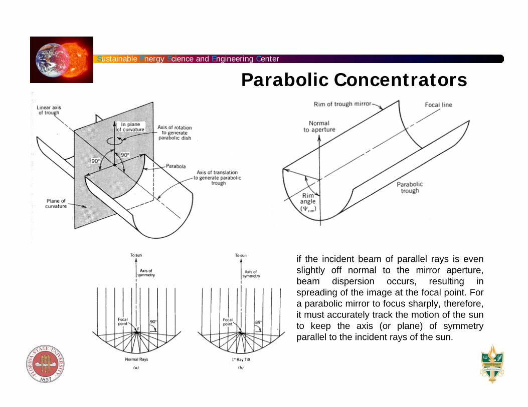
if the incident beam of parallel rays is even slightly off normal to the mirror aperture, beam dispersion occurs, resulting in spreading of the image at the focal point. For a parabolic mirror to focus sharply, therefore, it must accurately track the motion of the sun to keep the axis (or plane) of symmetry parallel to the incident rays of the sun.
Parabolic Concentrators
Sustainable Energy Science and Engineering Center
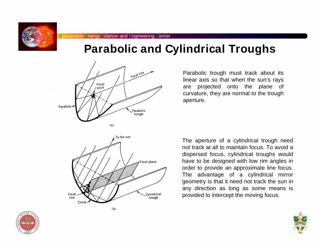
Parabolic trough must track about its linear axis so that when the sun’s rays are projected onto the plane of curvature, they are normal to the trough aperture.
The aperture of a cylindrical trough need not track at all to maintain focus. To avoid a dispersed focus, cylindrical troughs would have to be designed with low rim angles in order to provide an approximate line focus. The advantage of a cylindrical mirror geometry is that it need not track the sun in any direction as long as some means is provided to intercept the moving focus.
Parabolic and Cylindrical Troughs
Sustainable Energy Science and Engineering Center
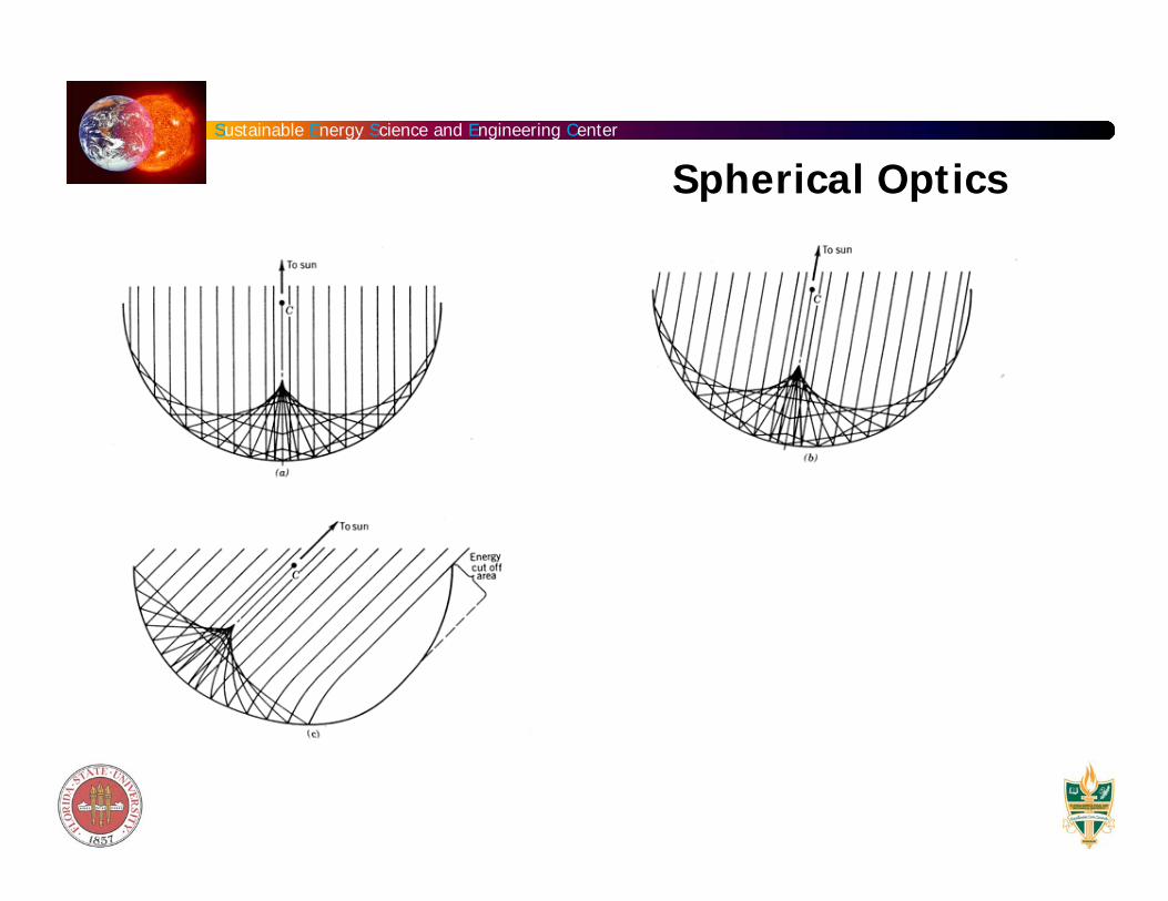
Spherical Optics
Sustainable Energy Science and Engineering Center
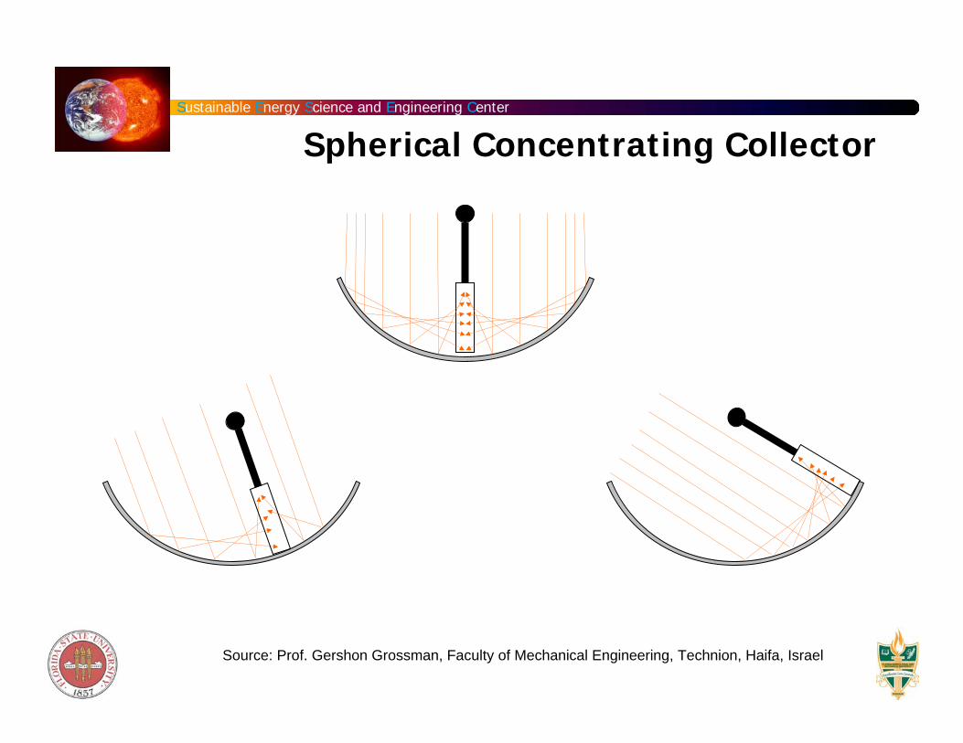
Spherical Concentrating Collector
Source: Prof. Gershon Grossman, Faculty of Mechanical Engineering, Technion, Haifa, Israel
Sustainable Energy Science and Engineering Center
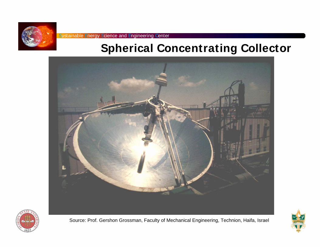
Source: Prof. Gershon Grossman, Faculty of Mechanical Engineering, Technion, Haifa, Israel
Spherical Concentrating Collector
Sustainable Energy Science and Engineering Center
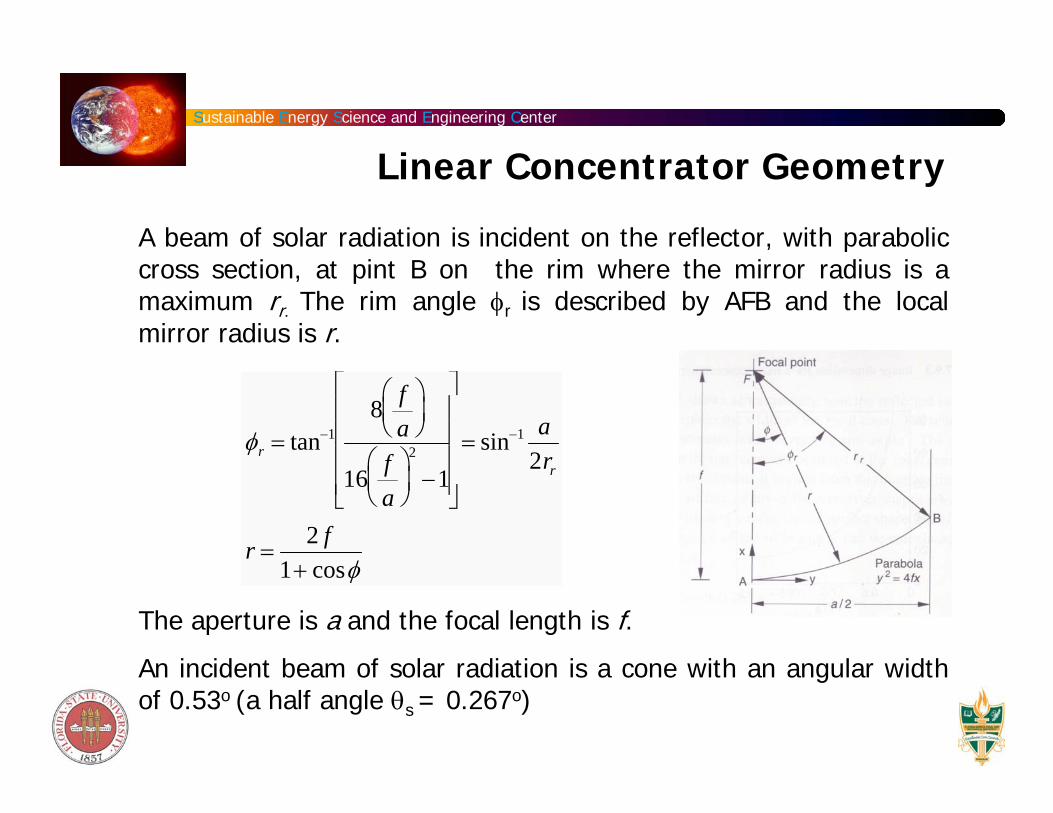
A beam of solar radiation is incident on the reflector, with parabolic cross section, at pint B on the rim where the mirror radius is a maximum rr. The rim angle φr is described by AFB and the local mirror radius is r.
The aperture is a and the focal length is f.
An incident beam of solar radiation is a cone with an angular width of 0.53o (a half angle θs = 0.267o)
φr = tan−18 f
a⎛ ⎝ ⎜
⎞ ⎠ ⎟
16 fa
⎛ ⎝ ⎜
⎞ ⎠ ⎟
2
−1
⎡
⎣
⎢ ⎢ ⎢ ⎢
⎤
⎦
⎥ ⎥ ⎥ ⎥
= sin−1 a2rr
r =2 f
1+ cosφ
Linear Concentrator Geometry
Sustainable Energy Science and Engineering Center
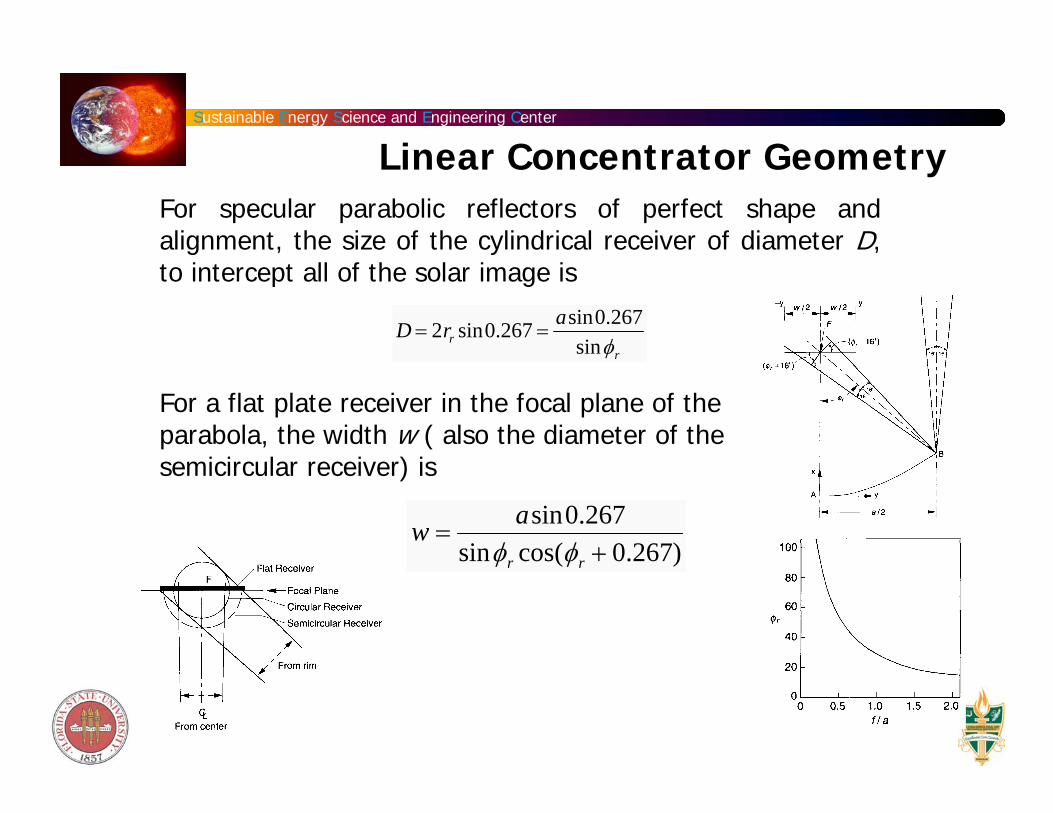
For specular parabolic reflectors of perfect shape and alignment, the size of the cylindrical receiver of diameter D, to intercept all of the solar image is
For a flat plate receiver in the focal plane of the parabola, the width w ( also the diameter of the semicircular receiver) is
D = 2rr sin0.267 =asin0.267
sinφr
w =asin0.267
sinφr cos(φr + 0.267)
Linear Concentrator Geometry
Sustainable Energy Science and Engineering Center
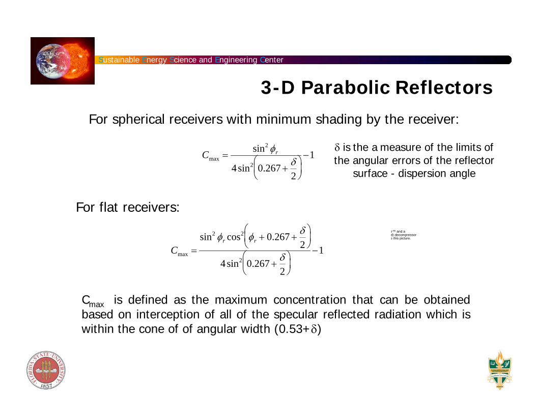
3-D Parabolic Reflectors
Cmax =sin2 φr
4sin2 0.267 +δ2
⎛ ⎝ ⎜
⎞ ⎠ ⎟
−1
For spherical receivers with minimum shading by the receiver:
δ is the a measure of the limits of the angular errors of the reflector
surface - dispersion angle
For flat receivers:
Cmax =sin2 φr cos2 φr + 0.267 +
δ2
⎛ ⎝ ⎜
⎞ ⎠ ⎟
4sin2 0.267 +δ2
⎛ ⎝ ⎜
⎞ ⎠ ⎟
−1
Cmax is defined as the maximum concentration that can be obtained based on interception of all of the specular reflected radiation which is within the cone of of angular width (0.53+δ)
e™ and ad) decompressore this picture.
Sustainable Energy Science and Engineering Center
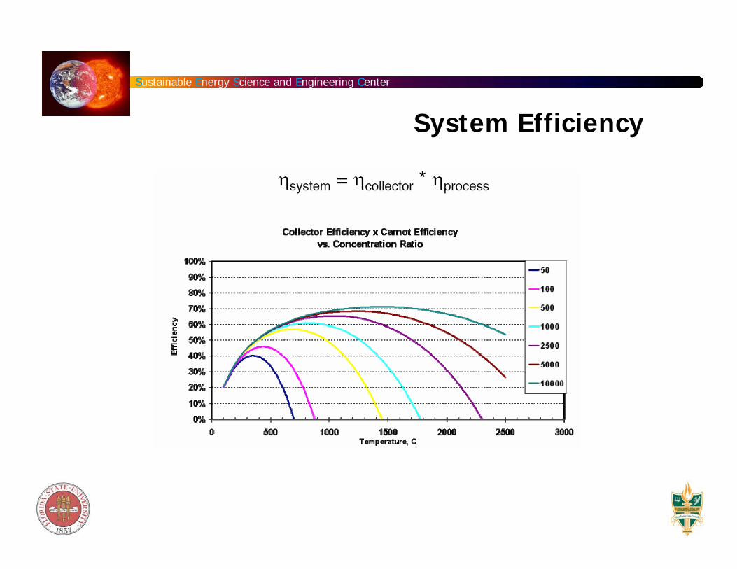
System Efficiency
Sustainable Energy Science and Engineering Center
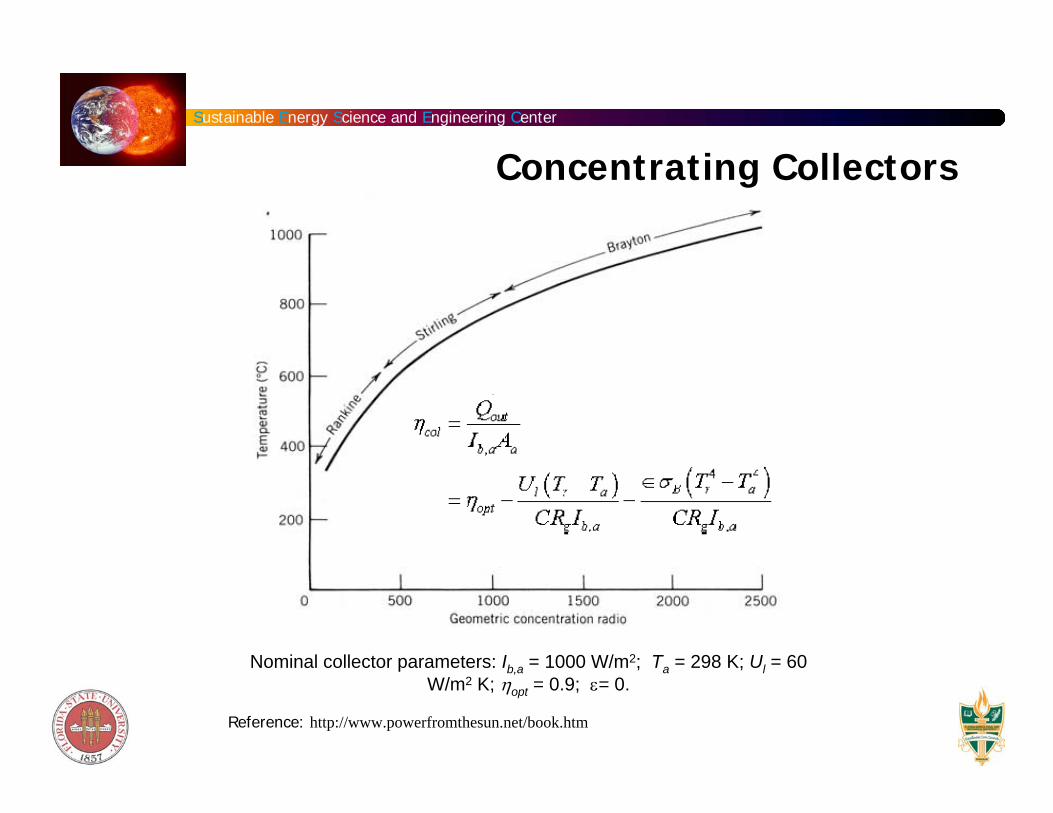
Concentrating Collectors
Reference: http://www.powerfromthesun.net/book.htm
Nominal collector parameters: Ib,a = 1000 W/m2; Ta = 298 K; Ul = 60 W/m2 K; ηopt = 0.9; ε= 0.
Sustainable Energy Science and Engineering Center
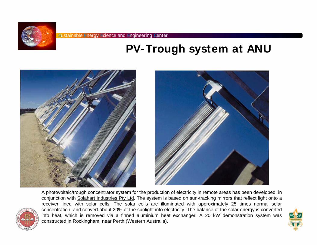
A photovoltaic/trough concentrator system for the production of electricity in remote areas has been developed, in conjunction with Solahart Industries Pty Ltd. The system is based on sun-tracking mirrors that reflect light onto a receiver lined with solar cells. The solar cells are illuminated with approximately 25 times normal solar concentration, and convert about 20% of the sunlight into electricity. The balance of the solar energy is converted into heat, which is removed via a finned aluminium heat exchanger. A 20 kW demonstration system was constructed in Rockingham, near Perth (Western Australia).
PV-Trough system at ANU
Sustainable Energy Science and Engineering Center
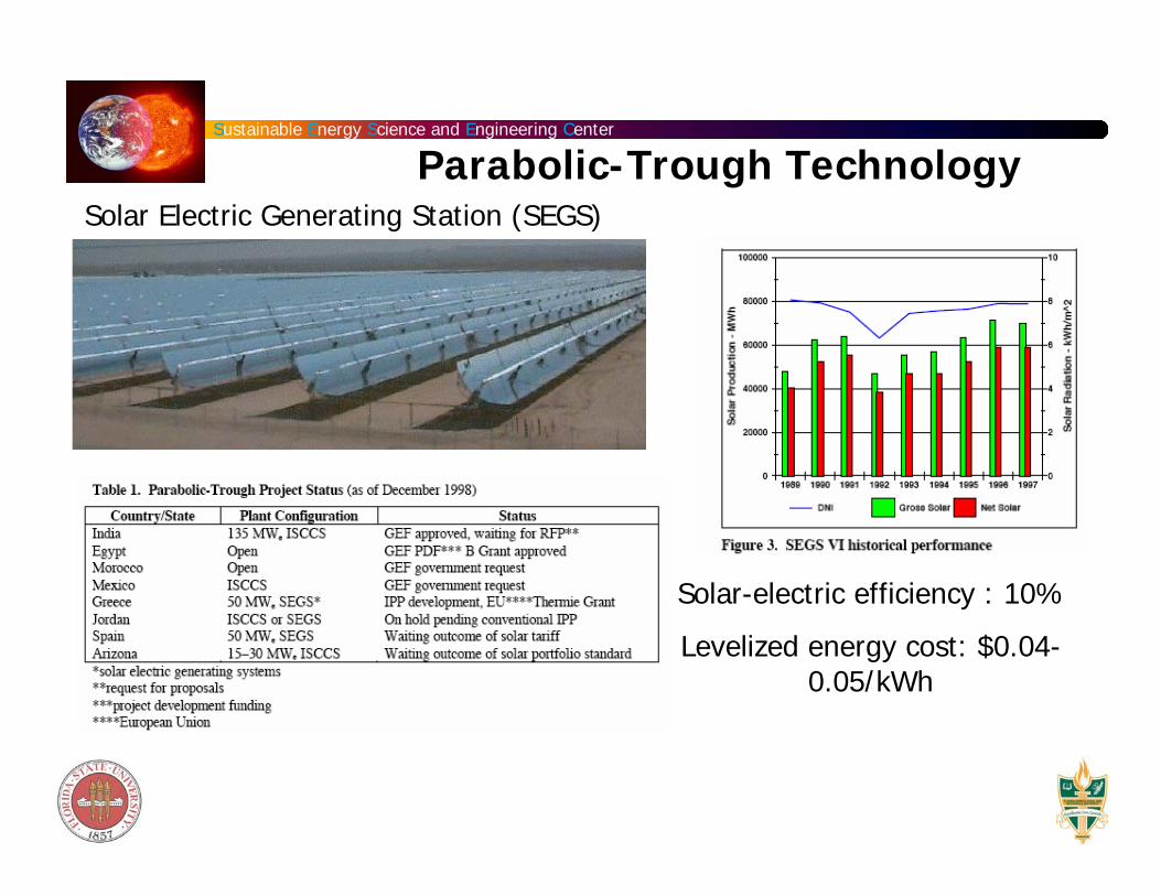
Parabolic-Trough Technology
Solar-electric efficiency : 10%
Levelized energy cost: $0.04-0.05/kWh
Solar Electric Generating Station (SEGS)
Sustainable Energy Science and Engineering Center
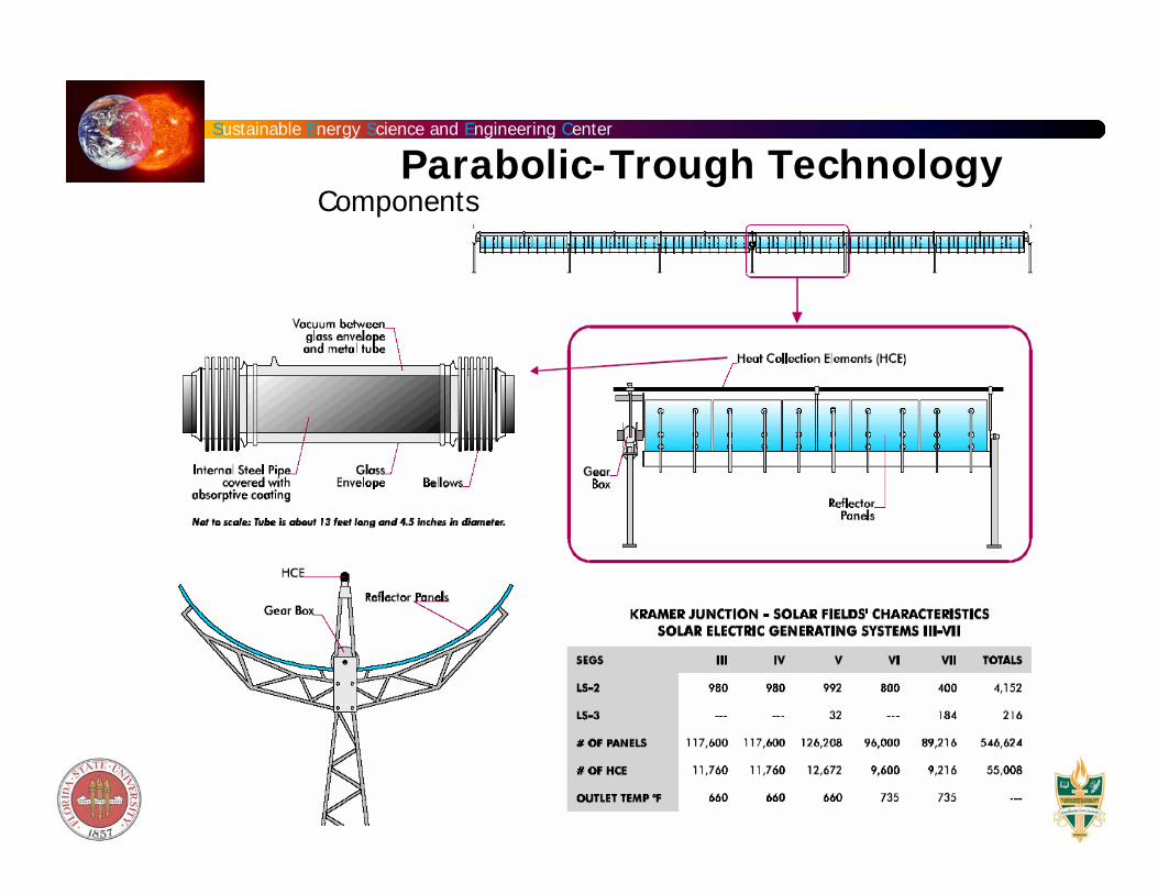
Parabolic-Trough TechnologyComponents

Sustainable Energy Science and Engineering Center
US Development Activity
Source: National Renewable Energy Laboratory
Parabolic-Trough Technology
Sustainable Energy Science and Engineering Center
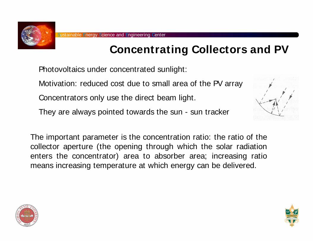
Concentrating Collectors and PV
Photovoltaics under concentrated sunlight:
Motivation: reduced cost due to small area of the PV array
Concentrators only use the direct beam light.
They are always pointed towards the sun - sun tracker
The important parameter is the concentration ratio: the ratio of the collector aperture (the opening through which the solar radiation enters the concentrator) area to absorber area; increasing ratiomeans increasing temperature at which energy can be delivered.
Sustainable Energy Science and Engineering Center
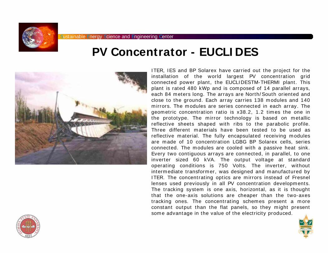
PV Concentrator - EUCLIDES ITER, IES and BP Solarex have carried out the project for the installation of the world largest PV concentration grid connected power plant, the EUCLIDESTM-THERMI plant. This plant is rated 480 kWp and is composed of 14 parallel arrays, each 84 meters long. The arrays are North/South oriented and close to the ground. Each array carries 138 modules and 140 mirrors. The modules are series connected in each array. The geometric concentration ratio is x38.2, 1.2 times the one in the prototype. The mirror technology is based on metallic reflective sheets shaped with ribs to the parabolic profile. Three different materials have been tested to be used as reflective material. The fully encapsulated receiving modules are made of 10 concentration LGBG BP Solarex cells, series connected. The modules are cooled with a passive heat sink. Every two contiguous arrays are connected, in parallel, to one inverter sized 60 kVA. The output voltage at standard operating conditions is 750 Volts. The inverter, without intermediate transformer, was designed and manufactured by ITER. The concentrating optics are mirrors instead of Fresnel lenses used previously in all PV concentration developments. The tracking system is one axis, horizontal, as it is thought that the one-axis solutions are cheaper than the two-axes tracking ones. The concentrating schemes present a more constant output than the flat panels, so they might present some advantage in the value of the electricity produced.
Sustainable Energy Science and Engineering Center
Project # 2: Design of a Parabolic Concentrating Collector for 1 kW power generation. Due: Feb 28th
1. Design parabolic dish to deliver 5 kW of thermal heat to a receiver that is to be located in Tallahassee.
2. Estimate for each month of the year.
3. Design a simple steam power plant to generate power using the thermal energy provided by the dish. Assume appropriate efficiencies for the components to be used.
Ý Q out