concept 16161 gb - nobel biocaredownload.nobelbiocare.com/webcontent/nobelguide/gsnobconc_161… ·...
TRANSCRIPT

NobelGuide™
perfect planning for perfect teeth
Importan
t!
Read thi
s manual
before
proceedi
ng with
implant
system m
anuals!
Procedures & Products – Powered by Procera®
ConceptRadiologistsCliniciansLaboratoriesand others working with NobelGuide™
Nobel Biocare is in compliance withISO 13485:2003 and Council Directive 93/42/EEC
Canadian Medical Devices Regulation
0086
For USA only: Federal law restricts this device to sale by or on the order of a licensed dentist or physician.All products are subject to change without notice.
Some products may not be available in all markets. Please contact your local Nobel Biocare officefor current product assortment and availability.
First from Nobel Biocare. NOBELPERFECT®, (NP, RP, WP), NOBELDIRECT® (NP, RP, WP), Brånemark System®, NOBELREPLACE™ and
NOBELSPEEDY™ Implants. A complete assortment with FDA clearance for Immediate Function™
in all single, partial and fully edentulous restorations in the mandible and maxilla.
Nobel Biocare AB and all production units are certified according to the Environmental Management System ISO 14001.
The procedures described herein must only be performed using components and instrumentsprovided by Nobel Biocare.
Nobel Biocare has published disclaimers relating to patient data and purchasing conditions. The latest versions of these disclaimers are available on the NobelGuide™ area on
the Nobel Biocare Extranet. Please ensure that you understand and accept these disclaimers.
Nobel Biocare reserves the right to make any necessary alterations to the methods and procedures stated in this manual.

3
quick start
Congratulations! You have made an excellent choice. Welcome to the Nobel Biocare family.
Getting started
Guided System Kits
• Brånemark System® Guided Surgery Kit• NobelReplace™ Tapered Guided Surgery Kit• NobelReplace™ Straight Guided Surgery Kit• NobelDirect® Guided Surgery Kit
Guided Drill Stop Kit
For combination with• Parallell wall implants
Procera Software
• Clinical Design Pro• Clinical Design Premium
How does it work (example)
Conventional approach NobelGuide™ approach
treatment planning
surgical procedure
relining
remove stiches
abutment connection
temporary prosthetic solution
soft-tissue control
impression
try in of prosthesis
final prosthetic solution
treatment planning
surgical procedure
temporary prosthetic solution
final prosthetic solution
Significantly reduced chairtime and increased profitability

4
temporization Teeth-in-an-Hour™
model-based planning
visualization of anatomy
computer-based planning
quick start

55
Concept OverviewBeautiful Teeth Now™
. . . . . . . . . . . . . . . . . . . . . . . . . . . . . . . . . . . . . . . . . . . . . . . . . . . . . . . . . . . . . . . . . . . . . . . . . 6Perfect Planning for Perfect Teeth . . . . . . . . . . . . . . . . . . . . . . . . . . . . . . . . . . . . . . . . . . . . . . . . . . . . . . . 7Patient Benefits . . . . . . . . . . . . . . . . . . . . . . . . . . . . . . . . . . . . . . . . . . . . . . . . . . . . . . . . . . . . . . . . . . . . . . . . . . . . . . . . . . 8Dental Professional Benefits . . . . . . . . . . . . . . . . . . . . . . . . . . . . . . . . . . . . . . . . . . . . . . . . . . . . . . . . . . . . . . . . 8
Model-Based Planning & ProcedureFlowchart. . . . . . . . . . . . . . . . . . . . . . . . . . . . . . . . . . . . . . . . . . . . . . . . . . . . . . . . . . . . . . . . . . . . . . . . . . . . . . . . . . . . . . . . . . . 9Examination of Patient and Treatment Planning. . . . . . . . . . . . . . . . . . . . . . . . . . . . . . . . 10Fabricate Stone Model . . . . . . . . . . . . . . . . . . . . . . . . . . . . . . . . . . . . . . . . . . . . . . . . . . . . . . . . . . . . . . . . . . . . . 10Planning on Model . . . . . . . . . . . . . . . . . . . . . . . . . . . . . . . . . . . . . . . . . . . . . . . . . . . . . . . . . . . . . . . . . . . . . . . . . . 10Fabricate Mapping Guide. . . . . . . . . . . . . . . . . . . . . . . . . . . . . . . . . . . . . . . . . . . . . . . . . . . . . . . . . . . . . . . . . 11Mapping. . . . . . . . . . . . . . . . . . . . . . . . . . . . . . . . . . . . . . . . . . . . . . . . . . . . . . . . . . . . . . . . . . . . . . . . . . . . . . . . . . . . . . . . . . 11Transfer mapping. . . . . . . . . . . . . . . . . . . . . . . . . . . . . . . . . . . . . . . . . . . . . . . . . . . . . . . . . . . . . . . . . . . . . . . . . . . . . 12Placement of Implant Replica . . . . . . . . . . . . . . . . . . . . . . . . . . . . . . . . . . . . . . . . . . . . . . . . . . . . . . . . . . . 13Fabricate Surgical Template . . . . . . . . . . . . . . . . . . . . . . . . . . . . . . . . . . . . . . . . . . . . . . . . . . . . . . . . . . . . . . 15
Computer-Based Planning & ProcedureFlowchart. . . . . . . . . . . . . . . . . . . . . . . . . . . . . . . . . . . . . . . . . . . . . . . . . . . . . . . . . . . . . . . . . . . . . . . . . . . . . . . . . . . . . . . . . 17Examination of patient and treatment evaluation. . . . . . . . . . . . . . . . . . . . . . . . . . . . . . 18Register patient in Procera® Software . . . . . . . . . . . . . . . . . . . . . . . . . . . . . . . . . . . . . . . . . . . . . . . . 18Prepare Radiographic Guide . . . . . . . . . . . . . . . . . . . . . . . . . . . . . . . . . . . . . . . . . . . . . . . . . . . . . . . . . . . . . 18CT Scan . . . . . . . . . . . . . . . . . . . . . . . . . . . . . . . . . . . . . . . . . . . . . . . . . . . . . . . . . . . . . . . . . . . . . . . . . . . . . . . . . . . . . . . . . . . 23Planning in Procera® Software. . . . . . . . . . . . . . . . . . . . . . . . . . . . . . . . . . . . . . . . . . . . . . . . . . . . . . . . . . . 24Order Surgical Template in Procera® Software . . . . . . . . . . . . . . . . . . . . . . . . . . . . . . . . . . . 26Fabricate Stone Model and Surgical Index . . . . . . . . . . . . . . . . . . . . . . . . . . . . . . . . . . . . . . . . 27
Prosthetic SolutionsFlowchart. . . . . . . . . . . . . . . . . . . . . . . . . . . . . . . . . . . . . . . . . . . . . . . . . . . . . . . . . . . . . . . . . . . . . . . . . . . . . . . . . . . . . . . . . 31
Clinical ProceduresFlowchart. . . . . . . . . . . . . . . . . . . . . . . . . . . . . . . . . . . . . . . . . . . . . . . . . . . . . . . . . . . . . . . . . . . . . . . . . . . . . . . . . . . . . . . . . 33One Tooth Missing. . . . . . . . . . . . . . . . . . . . . . . . . . . . . . . . . . . . . . . . . . . . . . . . . . . . . . . . . . . . . . . . . . . . . . . . . . . 34Several Teeth Missing . . . . . . . . . . . . . . . . . . . . . . . . . . . . . . . . . . . . . . . . . . . . . . . . . . . . . . . . . . . . . . . . . . . . . . . 35All Teeth Missing. . . . . . . . . . . . . . . . . . . . . . . . . . . . . . . . . . . . . . . . . . . . . . . . . . . . . . . . . . . . . . . . . . . . . . . . . . . . . . 36
AppendicesAppendix I – CT Scan. . . . . . . . . . . . . . . . . . . . . . . . . . . . . . . . . . . . . . . . . . . . . . . . . . . . . . . . . . . . . . . . . . . . . . . 37Appendix II – NobelGuide™ Implant Systems . . . . . . . . . . . . . . . . . . . . . . . . . . . . . . . . . . . . 43
Product Catalog . . . . . . . . . . . . . . . . . . . . . . . . . . . . . . . . . . . . . . . . . . . . . . . . . . . . . . . . . . . . . . . . . . . . . . . . . . . . . . . . . 44
Reference Guide . . . . . . . . . . . . . . . . . . . . . . . . . . . . . . . . . . . . . . . . . . . . . . . . . . . . . . . . . . . . . . . . . . . . . . . . . . . . . . . . . 48
table of contents

6
For abstracts, study references and for more information, please visitour website; www.nobelbiocare.com
Beautiful Teeth Now™
Nobel Biocare is providing dentists with more choices than everbefore. But our goals remain the same:
• To ensure that your patients leave the treatment roomsatisfied, comfortable, with beautiful teeth and with an improvedquality of life.
• To help your practice run more smoothly,efficiently and profitably.
This Concept Manual is designed to provide quick access to impor-tant information regarding NobelGuide™, read it before the implantsystem related manuals. The first section gives a general overall of the concept. The remaining sections go into more detail concerning Procera® Software, laboratory and CT scan procedures included in the concept.
A NobelGuide™ Training CD is included in the back cover of this manual complete with clinical movies featuring NobelGuide™.
Other related NobelGuide™ Instruction Material
• NobelGuide™ Procedures & Products Manuals for the following implant systems:Brånemark System® MkIII Groovy, NobelReplace™ Tapered Groovy,NobelReplace™ Straight Groovy, NobelSpeedy™ Groovy, NobelSpeedy™ Replace
• NobelGuide™ manual for NobelDirect®
• Integrated Procera® Software tutorials and help files
• NobelGuide™ Interactive Training CD
• NobelGuide™ area on the Nobel Biocare Extranet. This area includesonline training and FAQs
Important! While the NobelGuide™ methods described herein give you theopportunity to pre-plan and realize patient cases, medical responsibility forplanning and treatment remains that of the clinician.
concept overview

7
NobelGuide™
Model-based Computer-based
Temporization Teeth-in-an-Hour™
Perfect Planning for Perfect Teeth
The NobelGuide™ treatment concept from Nobel Biocare enablesyou to transform pre-planned treatment into clinical reality.
You decide! We provide!
You decide which planning method to use (model-based or computer-based). We provide you with the components you need to create acustomized Surgical Template according to your planning.
Based on the design of the Surgical Template, we then supply youwith the relevant surgical and laboratory instruments and implants tofacilitate the surgical procedure.
Prior to surgery, you can produce a temporary or final prosthesis thatcan be attached in the same session as the implant installation.
Indications: Totally and partially edentulous jaws, as well as single unit cases.
Main Benefit: Enables an easy, predictable, fast and minimally inva-sive dental implant and prosthetic delivery accordingto planning performed in advance.
NobelGuide™ components and instruments are available for treat-ment planning made in both computer-based and model-based environments.
Definitions
NobelGuide™: Cases where a Surgical Template, based on model- or computer-based planning, is used to guide the clinician during surgery.
Model-based planning: Surgical planning on stone model using estab-lished techniques. No CT scan data is required. Surgical Template is madeat laboratory.
Computer-based planning: CT scan data is basis for surgical planning in 3D computer environment. Surgical Template is made by Nobel Biocare.
Teeth-in-an-Hour™: The screw-retained, permanent prosthesis is attachedin the same surgery session.
concept overview

8
Patient Benefits
Maximum Comfort
The surgical treatment is based on guided keyhole surgery that isminimally invasive. This reduces pain and swelling considerably for the patient compared to conventional treatment. The new con-cept also reduces the number of appointments and chairtime for the patient, which means fewer interruptions in everyday life.
Cost-Saving
The patient can immediately return to work and/or social life after the treatment since the concept is built on Immediate Function™. For many patients this means a considerable cost-savings.
Fast Treatment
The combination of Immediate Function™ with temporary or final pros-thesis (Teeth-in-an-Hour™) ready at surgery radically shortens treatment.
Dental Professional Benefits
Increased Predictability and Safety
By planning your treatment and transforming this into a SurgicalTemplate you will achieve higher safety and predictability. Our 3D-surgical planning program results in exceptional predictability andoptimal implant placement.
Pre-production of Prosthetics
The planning will allow for pre-production of either the final or tem-porary prosthetics at implant level, or combined with your choice of abutments.
Total Solution Concept
We provide a complete solution supporting you from the planningstage to completed oral rehabilitation. The concept is powered by Procera® which makes the process simple and convenient.
Business Opportunity
The NobelGuide™ concept allows you to differentiate and develop your business to stay competitive. Reducing chairtime and patient visits for treatments allows you to increase your profitability and grow your business.
Reduced Inventory
Since clinicians know what instruments and components they need beforehand, this ensures minimal inventory requirements.
concept overview
9
Flowchart
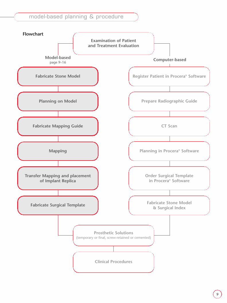
Prosthetic Solutions(temporary or final, screw-retained or cemented)
Clinical Procedures
Planning in Procera® Software
Register Patient in Procera® Software
Transfer Mapping and placement of Implant Replica
Fabricate Surgical Template
Order Surgical Template in Procera® Software
Fabricate Stone Model & Surgical Index
Fabricate Stone Model
Planning on Model
Fabricate Mapping Guide
Mapping
Prepare Radiographic Guide
CT Scan
Examination of Patient and Treatment Evaluation
Model-basedpage 9–16
Computer-based
model-based planning & procedure

10
Examination of Patient and Treatment Evaluation
NobelGuide™ Model-Based Planning, is intended for single and partially edentulous jaws where the patient:
• meets general health requirements for undergoing oral surgery• is fully healed after any dental grafting procedures• has a sufficient amount of jaw bone• has sufficient mouth opening capability to accommodate the
surgical tooling instrumentation.
Careful preoperative evaluation and investigation has to be carriedout, just as with any surgery using diagnostic radiographic imagingand other available investigation methods.
Note! Length of implants and mesio-distal direction has to be decidedbased on radiographic imaging to avoid interference with adjacent rootsand other anatomical structures.
There are several methods available for model-based planning. This manual will cover one mapping technique and two differentmethods to place the implant replicas.
• Make impressions of both jaws and take a bite registration.
Fabricate Stone Model
• Produce a stone model.
Planning of Model
• Mark the positions of the implants on the stone model with a stringof wax going from the buccal to the lingual side over the soft tissue.
model-based planning & procedure

11
model-based planning & procedure
Fabricate Mapping Guide
• Press a vacuum-pressed template over the stone model to make aMapping Guide.
• Make a series of holes in the line marked by the string of wax. It is recommended to have three buccal holes, three lingual/palatinal holes and one hole on top of the crest.
Mapping
• The Mapping Guide is placed in the patients mouth.
• Use a probe to perforate the soft tissue through the Mapping Guide.
• Measure the thickness of the soft tissue after removing the MappingGuide by using a probe with a plastic endodontic disc.

12
Transfer mapping
• Mark the positions of the holes on the stone model.
• Draw lines to connect the holes as indicated in the picture.
• Method A Section the stone modelin the line previously marked withthe string of wax – where theimplant should be placed.
• Method B Section the stonemodel according ordinarycrown and bridge work.
• The lines previously drawn on the stone model give the correct position for each depth measurement.
• Mark the mucosa thickness measurements on the side of the sectioned stone model.
• Grind down the stone model sections according to the bone-profile, exposing the topogra-phy of the underlying bone.
model-based planning & procedure
Method A Method B
13
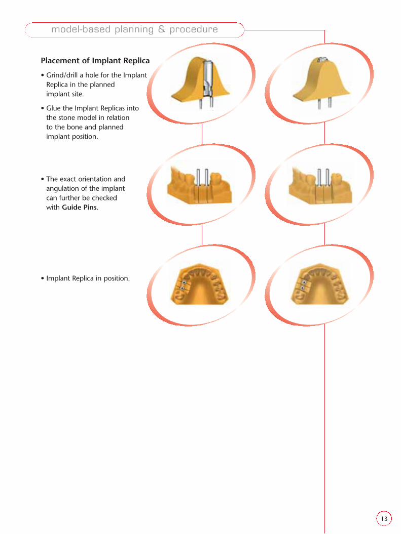
Placement of Implant Replica
• Grind/drill a hole for the Implant Replica in the planned implant site.
• Glue the Implant Replicas into the stone model in relation to the bone and planned implant position.
• The exact orientation and angulation of the implant can further be checked with Guide Pins.
• Implant Replica in position.
model-based planning & procedure

14
model-based planning & procedure
Soft Tissue Replica
• Use the Mapping Guide as a mold for Soft Tissue Replica.
• Uncover the Implant Replica by using a Soft Tissue Punch.
15
2
3
1
4
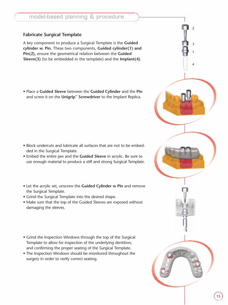
Fabricate Surgical Template
A key component to produce a Surgical Template is the Guidedcylinder w. Pin. These two components, Guided cylinder(1) andPin(2), ensure the geometrical relation between the GuidedSleeve(3) (to be embedded in the template) and the Implant(4).
• Place a Guided Sleeve between the Guided Cylinder and the Pinand screw it on the Unigrip™ Screwdriver to the Implant Replica.
• Block undercuts and lubricate all surfaces that are not to be embed-ded in the Surgical Template.
• Embed the entire jaw and the Guided Sleeve in acrylic. Be sure touse enough material to produce a stiff and strong Surgical Template.
• Let the acrylic set, unscrew the Guided Cylinder w Pin and removethe Surgical Template.
• Grind the Surgical Template into the desired shape. • Make sure that the top of the Guided Sleeves are exposed without
damaging the sleeves.
• Grind the Inspection Windows through the top of the Surgical Template to allow for inspection of the underlying dentition, and confirming the proper seating of the Surgical Template.
• The Inspection Windows should be monitored throughout the surgery in order to verify correct seating.
model-based planning & procedure

16
When carrying out a Guided Surgery prosthetic procedure, a widerange of Nobel Biocare abutments can be used, such as:
– Immediate Temporary Abutment (for single cases)– Guided Abutment (for partial edentulous cases)– Procera® Abutment– Snappy Abutment™
– Esthetic Abutment– Multi-Unit Abutment
• For this indication the Procera® Abutment Zirconia is fabricated.
• A temporary bridge is fabricated in the laboratory prior to surgery.
Implant Placement
• The Surgery is performed according to the surgical procedure asdescribed in the relevant NobelGuide™ Procedures & Products manuals using the lab-made Surgical Template.
Prosthetic Procedure
• Proceed with the prosthetic procedures to connect the abutmentsand make a temporary cementation of the bridge.
• Follow established prosthetic procedures to make the final restora-tion after a sufficient healing period.
model-based planning & procedure

17
FlowchartExamination of Patient
and Treatment Evaluation
Model-based Computer-basedpage 17–30
computer-based planning & procedure
Prosthetic Solutions(temporary or final, screw-retained or cemented)
Clinical Procedures
Planning in Procera® Software
Register Patient in Procera® Software
Transfer Mapping and placement of Implant Replica
Fabricate Surgical Template
Order Surgical Template in Procera® Software
Fabricate Stone Model & Surgical Index
Fabricate Stone Model
Planning on Model
Fabricate Mapping Guide
Mapping
Prepare Radiographic Guide
CT Scan

18
Examination of Patient and Treatment Evaluation
NobelGuide™ Computer-Based Planning is intended for single, partialand fully edentulous jaws where the patient:
• meets general health requirements for undergoing oral surgery• is fully healed after any dental grafting procedures• has a sufficient amount of jaw bone• has sufficient mouth opening capability to accommodate the
surgical tooling
Register Patient in Procera® Software
Procera® Software guides you through the computer-based NobelGuide™ process. It is also used to access the Procera®
Software Planning Program – Surgical (see page 24).
• Use Procera® Software to register the patient and to receive a Treatment ID number.
Prepare Radiographic Guide
• Make an impression of both jaws and a bite registration index. The index should be made using stiff material.
• For fully edentulous jaws, the bite registration should be madeusing the existing optimized prosthesis or, if needed, a newly pro-duced prosthesis = Radiographic Guide.
If the patient only has a few teeth in the opposing jaw and does notwear a partial prosthesis, make sure to fill up the area where the teethare missing with occlusion index material to make contact with thealveolar ridge. This is to ensure that you have a horizontal, well-balanced bite registration.
Radiographic Guide
The Radiographic Guide is used to simulate the teeth, the soft tissuesurface and edentulous space during the CT scan (see page 37). Thecorrect design of the Radiographic Guide is a pre-requisite for success-ful treatment since the final outcome of the rehabilitation is determinedby the Radiographic Guide.
When fabricating a Radiographic Guide, please note that material hasto be of acrylic or with similar density.
– In fully edentulous cases, the existing optimized prosthesis or, if needed, a newly produced prosthesis should be used.
– In single and partial cases, instruct your laboratory to fabricate anacrylic Radiographic Guide.
computer-based planning & procedure

19
General design requirements Radiographic Guide
• Optimal representation of position of the restored teeth
• Optimal fit to anatomy, including;– Palate (if applicable)– Gingiva– Existing denture (if applicable), covering buccal, lingual and
occlusal aspects
• Extend over the buccal and lingual soft tissue to the vestibularextension
• Has an ideal set-up of teeth in terms of occlusion, position, occlusalheight & lip support
• Inspection windows should be made in partial and single cases
• Made in a non radio-opaque material, i.e. acrylic
• Extend back to the retromolar area
• Gutta-percha markers should be inserted
computer-based planning & procedure

20
Radiographic Guide – Surgical Template
The geometry of Radiographic Guide is transferred to the Surgical Template.
Fully edentulous cases
• Use existing optimized prosthesis, or a specially produced prosthe-sis, Radiographic Guide, where the teeth are more optimally placedfor lip support, height etc
• Cover a sufficient part of the gingiva to accommodate for GuidedAnchor Pin placement
• Ensure that the Anchor Pins have a large enough base of thick mate-rial for optimal stiffness of the Anchor Pin Sleeves
• This can be further verified in the Planning Program
Single & Partial case
• Fabricate stone models of the patient’s jaws based on the impressions
• Set up the stone model in the articulator using the bite registration index
computer-based planning & procedure
21
• Make a diagnostic wax-up of the patient’s tooth/teeth to berestored on the stone model
• Cover the existing teeth down to the vestibular extension with a >2,5–3 mm thick resin material. Also, cover palate if applicable. Be sure to block all undercuts.
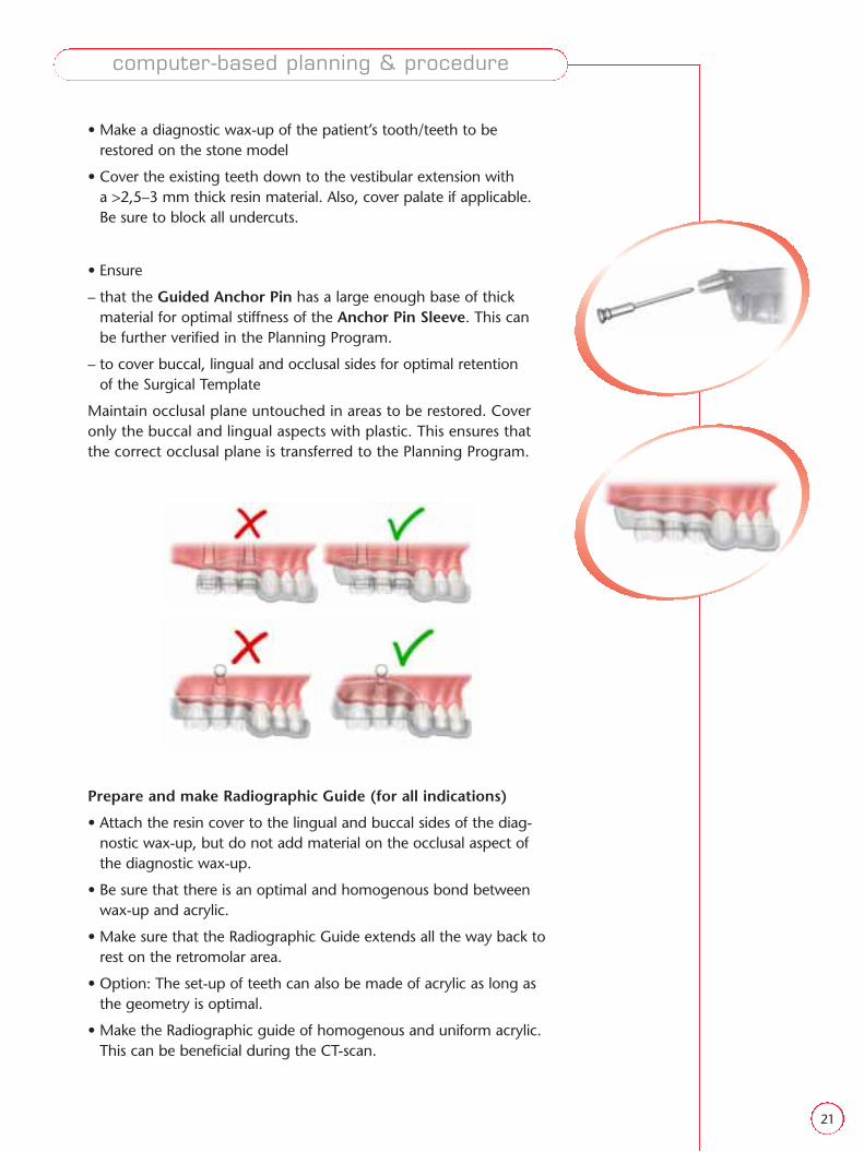
• Ensure
– that the Guided Anchor Pin has a large enough base of thick material for optimal stiffness of the Anchor Pin Sleeve. This can be further verified in the Planning Program.
– to cover buccal, lingual and occlusal sides for optimal retention of the Surgical Template
Maintain occlusal plane untouched in areas to be restored. Coveronly the buccal and lingual aspects with plastic. This ensures thatthe correct occlusal plane is transferred to the Planning Program.
Prepare and make Radiographic Guide (for all indications)
• Attach the resin cover to the lingual and buccal sides of the diag-nostic wax-up, but do not add material on the occlusal aspect ofthe diagnostic wax-up.
• Be sure that there is an optimal and homogenous bond betweenwax-up and acrylic.
• Make sure that the Radiographic Guide extends all the way back torest on the retromolar area.
• Option: The set-up of teeth can also be made of acrylic as long asthe geometry is optimal.
• Make the Radiographic guide of homogenous and uniform acrylic.This can be beneficial during the CT-scan.
computer-based planning & procedure

22
Reference Points (for all indications)
To facilitate the double CT scanning technique and the subsequentmatching of the two CT scans in Procera® Software, six referencepoints must be inserted into the Radiographic Guide.
• Make 6 small holes (∅ 1.5 mm) in the Radiographic Guide. The holes should be no more than 1 mm deep.
• Place two of the reference points lingually/palatally to the canines,two disto-buccally to the premolars and two in the molar region.
• Place the reference points at different levels in relation to theocclusal plane.
• Fill the holes with gutta-percha.
– In single and partial cases where metal fillings are present in theexisting denture, place the reference points on levels other thanthose of the fillings, for example, below the teeth.
Inspection windows (Partial and Single cases)
• The inspection windows made on single and partial RadiographicGuides are transferred to the Surgical Template where they allowinspection of the underlying dentition, thus confirming the properseating of the Surgical Template during surgery.
• Make inspection windows in the Radiographic Guide through theocclusal surface over the existing dentition.
• Make 3–4 windows evenly distributed over the entire arch whereone or two windows are located adjacent to the area to be restored.
• The inspection windows should preferably be placed over a cusp ora corner of a tooth so that the underlying dentition protrudesthrough the window.
computer-based planning & procedure

23
Radiographic Index
For fully edentulous cases the bite registration index is the Radiographic Index.
For partial and single cases prepare Radiographic Index.
• Insert the Radiographic Guide in the articulator and, using stiffmaterial make an occlusal index between the Radiographic Guideand the opposing dentition.
Note in partial cases! If the patient only has a few teeth in the opposingjaw and does not wear a partial prosthesis, make sure to fill up the areawhere the teeth are missing with occlusion index material to make con-tact with the alveolar ridge. This is to ensure that you have a horizontal,well-balanced bite registration.
Deliver the Radiographic Guide and the Radiographic Index to beused during CT scan.
CT Scan
Double scanning technique (see page 37)
1. Patient wearing Radiographic Guide and Radiographic Index.
2. Radiographic Guide on its own Planning Program Surgical applica-tion, and order Convert the CT DICOM files into a file format com-patible with Procera® Software Planning Program – Surgical.
Computer-based Planning
• Plan the patient in the Procera® Software Planning Program Surgicalapplication, and order all necessary components including thecustomized Surgical Template and Duplicate Denture (if neededfor lab work).
computer-based planning & procedure
24
Planning in Procera® Software
Procera® Software is used to guide you through the computer-based NobelGuide™
process. It is also used to access the Procera® Software Planning Program – Surgical (seenext page). Procera® Software is available in two versions for NobelGuide™ applications:
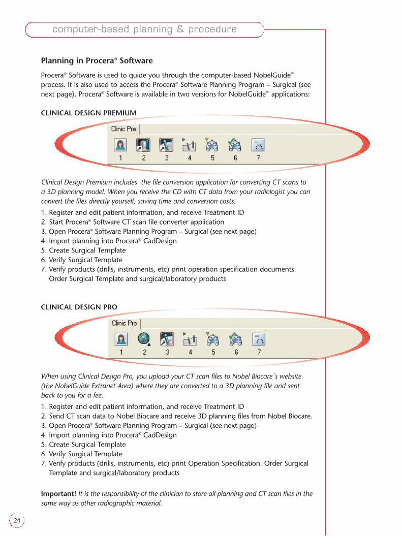
CLINICAL DESIGN PREMIUM
Clinical Design Premium includes the file conversion application for converting CT scans to a 3D planning model. When you receive the CD with CT data from your radiologist you canconvert the files directly yourself, saving time and conversion costs.
1. Register and edit patient information, and receive Treatment ID2. Start Procera® Software CT scan file converter application3. Open Procera® Software Planning Program – Surgical (see next page)4. Import planning into Procera® CadDesign5. Create Surgical Template6. Verify Surgical Template7. Verify products (drills, instruments, etc) print operation specification documents.
Order Surgical Template and surgical/laboratory products
CLINICAL DESIGN PRO
When using Clinical Design Pro, you upload your CT scan files to Nobel Biocare´s website (the NobelGuide Extranet Area) where they are converted to a 3D planning file and sentback to you for a fee.
1. Register and edit patient information, and receive Treatment ID2. Send CT scan data to Nobel Biocare and receive 3D planning files from Nobel Biocare.3. Open Procera® Software Planning Program – Surgical (see next page)4. Import planning into Procera® CadDesign5. Create Surgical Template6. Verify Surgical Template7. Verify products (drills, instruments, etc) print Operation Specification. Order Surgical
Template and surgical/laboratory products
Important! It is the responsibility of the clinician to store all planning and CT scan files in thesame way as other radiographic material.
computer-based planning & procedure

25
Requirements
Operating system Windows 2000, Service Pack 4 or Windows XP Professional, Service Pack 2
Processor 2 GHz Pentium® IV or equivalent
Internal memory 512 MB
Graphics card* Recent nVIDIA card with nVIDIA’s latest drivers installed & internal memory of 128 MB
Monitor resolution 1024x768 or higher
Hard disk 40GB
Internet connection Broadband
Procera® Software – Computer Requirements
We recommend that you install the Procera® System on a dedicated stand-alone computer according to the latest hardware recommendations.
• Procera® Software Planning Program – Clinical Design is a three-dimensional (3D) image-based environment for planning the posi-tion and orientation of dental implants. It is used to determine theoptimal sites for implant placement, taking into account anatomicalconstraints and also prosthetic and esthetic considerations.
• The planning environment is based on the concept of representinga 3D medical image volume as a 3D scene.
• This approach bridges the gap between conventional (stacks of)two-dimensional radiological images and the actual view on apatient in the operating theatre.
• In a 3D scene, you gain a good understanding of the patient’sanatomy in relation to implant components, as well as to the prosthetic situation.
• Each planning process is unique and is based entirely upon the specific considerations and prerequisites that are present for eachindividual patient.
• The implant sites have to be planned with a minimum distance fromcenter-to-center depending on which platform(s) you are using.
• The yellow zone around implants indicates a distance of 1.5 mm.
Procera® Software Planning Program – Clinical Design
computer-based planning & procedure
*Please note that an nVIDIA graphics card is required for the software to function

26
All Teeth Missing: Three Anchor Pins (∅ 1.5 mm) are planned in thejawbone between the implants in an axial plane to enable proper sta-bilization of the Surgical Template during surgery.
Several Teeth Missing: A minimum of one Anchor Pin is recommended.
One Tooth Missing: The Surgical Template is retained on the existingdenture only.
For more information about the planning procedure and Procera®
Software Planning Program – Clinical Design, see:
– NobelGuide™ area on Nobel Biocare Extranet
– Integrated Software tutorial
– Procera® Software Planning Program help file
Order Surgical Template in Procera® Software
• When you have finished your planning, you must verify andapprove it.
• Order the Surgical Template using the Procera® Software.
Surgical Template and Surgical Index
• Once you have received the surgical Template, verify that the Treatment ID Number is correct and instruct your lab to fabricate:
– Stone model
– Surgical Index
– Temporary/final prosthesis
• Ensure that the mechanical strength of the Surgical Template is suffi-cient. Recommended thickness is 2.5–3 mm. Reinforce, if required,by adding plates or gel from a light cured tray material (e.g. Triad). Ifadding material, be sure to leave the top of the Sleeves untouchedso that the reference level is maintained.
• Ensure that the Surgical Template can be correctly positioned on the teeth. Use the Inspection Window to check the position. Adjust,if required.
• Make the Surgical Index
computer-based planning & procedure

27
3
4
2
1
6
5
Fabricate Stone Model and Surgical Index
General
The Surgical Index is used during surgery to position the SurgicalTemplate on the jaw before anchoring it with Anchor Pins.
The Surgical Template is developed in a CAD environment and con-tains all the necessary information for making the stone model, onwhich a permanent or a temporary prosthesis can be fabricated.
Important information about Surgical Template
• The Surgical Template is made of a material that is sensitive to moisture and UV light. Store the Surgical Template together with a moisture absorbent in the UV protective plastic bag in which it was delivered.
• Always store the Surgical Template in a dry and dark location.• Never expose the Surgical Template to direct sunlight.• Never remove the moisture absorbent.• Use a high level disinfectant (eg CidexOPA Solution) for
12 minutes at room temperature. Rinse thoroughly with sterilewater. Dry quickly but without using heat.
Caution! The Surgical Template may deform if exposed to liquids (even water) for more than 30 minutes.
Workflow (Fully Edentulous Case)
• Verify that the Surgical Template has the correct Treatment IDengraved on the lingual aspect and that the overall geometry of theSurgical Template is similar to that of the Radiographic Guide.
A key component to produce a Surgical Template is the Guided cylinder w. Pin. These two components Guided cylinder(1) andPin(2) ensure the geometrical relation between the GuidedSleeve(3) and the Implant.
• Mount Implant Replicas(4) in each of the holes in the SurgicalTemplate using the Guided Cylinder with Pin. The replicas andtype of Guided Cylinder to use are specified in the documentsaccompanying the case.
• Insert Anchor Pins(5) into Anchor Pin sleeves(6).
• Use vaseline to lubricate the bottom of the Guided Cylinder with Pinand the top surface of the Surgical Template for easier dismountingof the soft-tissue replica.
• Add soft-tissue replica. Use a very small tube to ensure that you canreach right down to the Guided Cylinder with Pin.
computer-based planning & procedure

28
• Use soft-tissue replica or boxing wax on the buccal side of thevestibular extension to prevent the Surgical Template from lockingafter the plaster has set.
• Pour in die stone model plaster.
• Use a plaster box to facilitate the manufacturing of the stone model.
• After the plaster has set, remove the Anchor Pins.
• Next remove the Guided Cylinder with Pin, using a Unigrip™ Screw-driver, and the Surgical Template.
• Use a cutter to remove the high edges around the holes.
• Attach the Duplicate Denture (ordered via Procera® Software Plan-ning Program – Surgical) or the patient’s optimized prosthesis ontothe stone model and mount the stone model in an articulatortogether with the model of the opposing jaw. Use the RadiographicOcclusal Index to verify the correct occlusion.
• Replace the Radiographic Guide with the Surgical Template andsecure it with Anchor Pins.
• Add index material (e.g. A-silicone) on top of the Surgical Template.
Note! If the patient only has front teeth in the opposing jaw and does notwear a partial prosthesis, build up the bite in the area where the teeth aremissing to ensure contact with the alveolar ridge. This is to ensure thatyou have a horizontal, well-balanced bite registration.
• Add a string of index material on the opposite jaw and bite the jawstogether.
• Make sure you have enough material to get a good index.
• Put the Surgical Template back in the UV-protective plastic bag inwhich it was delivered (see storage instructions on page 27).
You now have a finished Surgical Template and Surgical Index, to be usedduring surgery.
computer-based planning & procedure

29
2
3
1
4
5
Workflow (Single & Partially Edentulous Cases)
• Verify that the Surgical Template has the correct Treatment IDengraved on the lingual aspect.
• Verify the proper seating of the Surgical Template onto the originalstone model of the patient using visual inspection through theinspection windows.
• Mark the approximate locations of the implants on the model.
• Cut away the section to be restored on the stone model in order to make room for the Implant Replicas.
A key component to produce a Surgical Template is the Guided cylinder w. Pin. These two components Guided cylinder(1) andPin(2) ensure the geometrical relation between the GuidedSleeve(3) and the Implant.
• Mount Implant Replicas(4) in each of the holes in the SurgicalTemplate using the Guided Cylinder with Pin. The replicas andtype of Guided Cylinder to use are specified in the documentsaccompanying the case.
• Verify that the mounted Implant Replicas fit in the cut-away sectionof the stone model.
• Mount Anchor Pins(5) in Surgical Template if applicable.
Note! When you use an engaging abutment (i.e. a rotational lock abutment), care must be taken to rotate the Implant Replicas so that theside of the hex is parallel with the curvature of the jaw (BrånemarkSystem®), or so that a lobe of the internal connection is oriented buccally(NobelReplace™).
• Use vaseline to lubricate the bottom of the Guided Cylinder with Pin and the surface of the Surgical Template for easier dismountingof the soft-tissue replica.
• Add soft-tissue replica in the area of the restoration. Use a very small tube to ensure that you can reach right down to the GuidedCylinder with Pin.
• Position the Surgical Template on the Stone Model. Add some sticky wax to secure the proper positioning of the Surgical Tem-plate. Verify the proper seating of the Surgical Template via the inspection windows.
• Fill the area to be restored with die stone.
• Verify the proper seating of the Surgical Template via the inspectionwindows throughout the stone’s setting process.
computer-based planning & procedure

30
5
• Once the plaster has set, unscrew and remove the Guided Cylinderwith Pin, the Anchor Pins and the Surgical Template.
• Remove any high edges around the template cylinder holes.
• Attach the Radiographic Guide onto the stone model and mount itin an articulator together with a stone model of the opposing jawand the Radiographic Index.
• Replace the Radiographic Guide with the Surgical Template and verify the correct position through the inspection windows.
• If applicable, secure the Surgical Template with Anchor Pins.
• Add index material (e.g. Silcone A) between the Surgical Templateand the opposite jaw, and bite the jaws together.
• Make sure you have enough material to get a good index.
Note! If the patient only has front teeth in the opposing jaw and does notwear a partial prosthesis, build up the bite in the area where the teeth aremissing to ensure contact with the alveolar ridge. This is to ensure thatyou have a horizontal, well-balanced bite registration.
• Put the Surgical Template back in the UV-protective plastic bag inwhich it was delivered (see storage instructions on page 27)
You now have a finished Surgical Template and a Surgical Index, to beused during surgery.
computer-based planning & procedure

31
Flowchart
Prosthetic Solutions(temporary or final, screw-retained or cemented)
Page 31–32
Clinical Procedures
Examination of Patient and Treatment Evaluation
Model-based Computer-based
prosthetic solutions
Transfer Mapping and placement of Implant Replica
Fabricate Surgical Template
Fabricate Stone Model
Planning on Model
Fabricate Mapping Guide
Mapping Planning in Procera® Software
Register Patient in Procera® Software
Order Surgical Template in Procera® Software
Fabricate Stone Model & Surgical Index
Prepare Radiographic Guide
CT Scan

32
3
2
1
4
prosthetic solutions
Prosthetic Solutions
NobelGuide™ provides you with complete freedom to choose theappropriate prosthetic solution to satisfy patient requirements as wellas the clinical situation.
When carrying out a Guided Surgery prosthetic procedure, a widerange of Nobel Biocare abutments can be used, such as:
– Immediate Temporary Abutment (for single cases)– Guided Abutment (for partial and fully edentulous cases)– Procera® Abutment– Snappy Abutment™
– Esthetic Abutment– Multi-Unit Abutment
In both model-based and computer-based procedures, after the pro-duction of the stone model, most prosthetic procedures are the sameas those for conventional treatment.
Teeth-in-an-Hour™ solutions
Below is a description for NobelGuide™ screw-retained solutions basedon adjustable Guided Abutments:
• Make a set-up of teeth in the articulator.
• If possible, use the set-up of the Radiographic Guide as a template.
• Make a silicone key to be able to replace the teeth in the same posi-tion on top of the model.
• Mount the Guided Laboratory Abutment(1) and Guided Ti Temporary Coping(2) together and connect them to the ImplantReplica(4) using Guide Pin(3) and Unigrip™ Screwdriver.
• Make a resin replica of the bridge frame into which the Guided TiTemporary Copings are embedded.
• Make a new silicone key that follows the frame. Put some siliconeunder the frame to create the space for the surrounding acrylic.
• Send the Resin Frame and Stone Model to Nobel Biocare’s productionfacilities according to normal procedures for Procera® Implant Bridge.
• Once it is returned, follow normal finishing procedures.
Note! The Guided Ti Copings can also be used for temporary restorations.
See the Nobel Biocare Laboratory Procedures manual for more information relating to other prosthetic procedures.

33
Flowchart
Prosthetic Solutions(temporary or final, screw-retained or cemented...)
Clinical ProceduresPage 33–36
Model-based Computer-based
clinical procedures
Examination of Patient and Treatment Evaluation
Transfer Mapping and placement of Implant Replica
Fabricate Surgical Template
Fabricate Stone Model
Planning on Model
Fabricate Mapping Guide
Mapping Planning in Procera® Software
Register Patient in Procera® Software
Order Surgical Template in Procera® Software
Fabricate Stone Model & Surgical Index
Prepare Radiographic Guide
CT Scan

34
surgical procedure
Position Surgical Template Installation of Implant
Abutment Connection Cementation of Temporary
prosthetic option: temporization
Below are Quick Start examples of the surgical and prosthetic procedures relating to NobelGuide™. For a complete description see the relevant NobelGuide™ Clinical Procedure and Product Catalog.
One Tooth Missing
clinical procedures
35
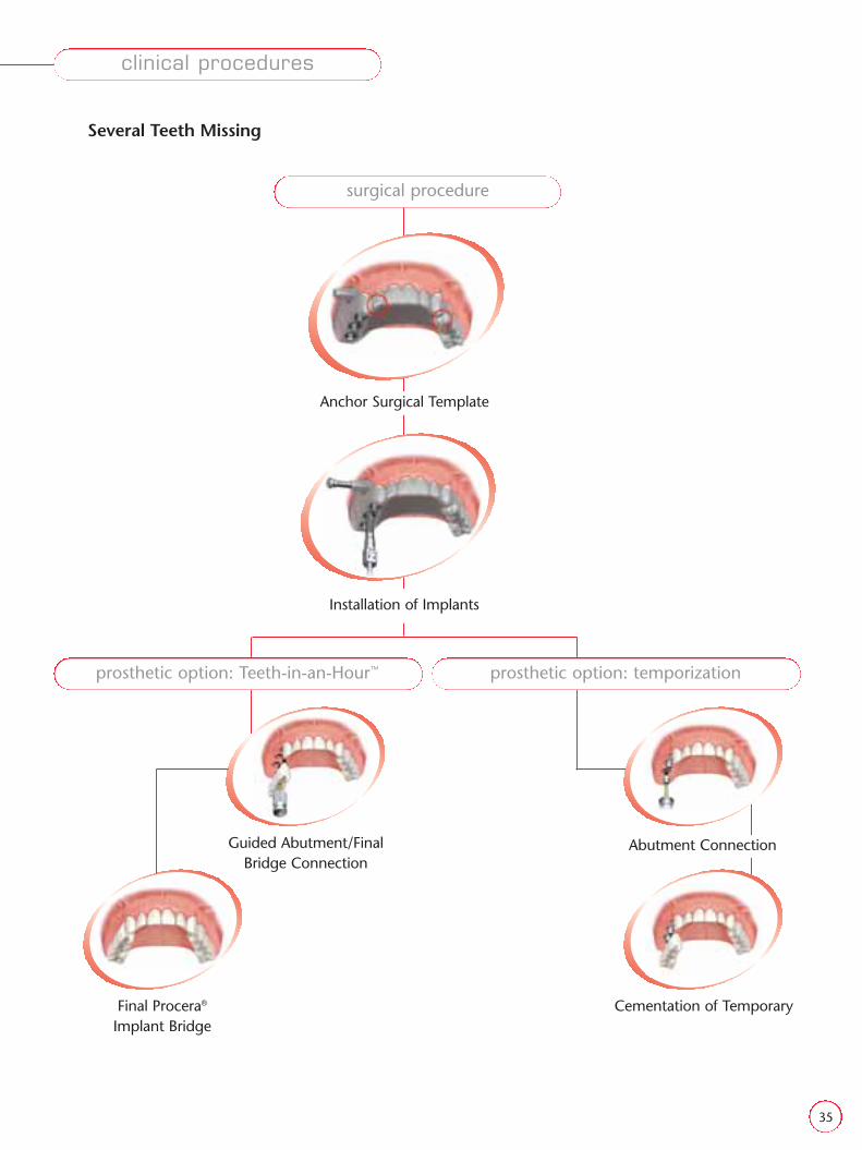
Guided Abutment/FinalBridge Connection
Final Procera®
Implant BridgeCementation of Temporary
Abutment Connection
prosthetic option: Teeth-in-an-Hour™ prosthetic option: temporization
Several Teeth Missing
surgical procedure
Anchor Surgical Template
Installation of Implants
clinical procedures
36
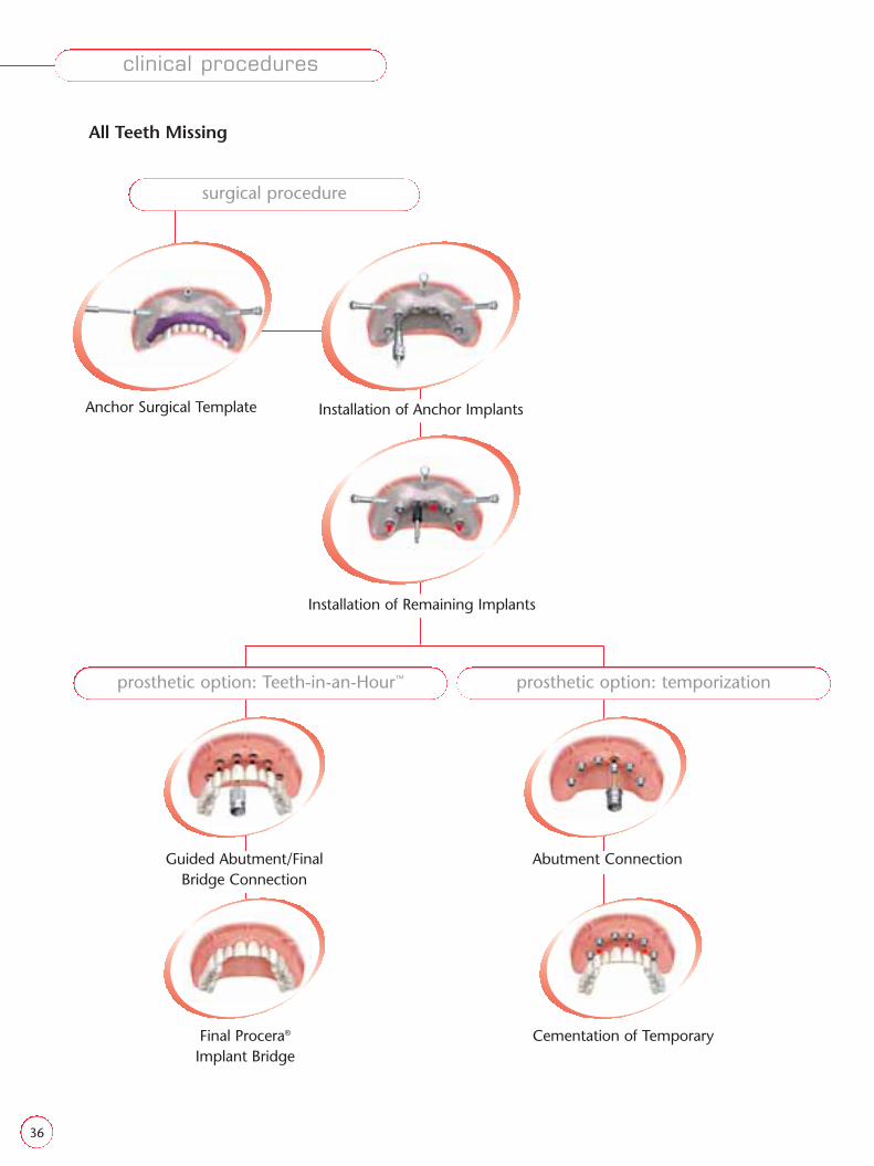
All Teeth Missing
Final Procera®
Implant BridgeCementation of Temporary
Guided Abutment/FinalBridge Connection
Abutment Connection
prosthetic option: Teeth-in-an-Hour™ prosthetic option: temporization
surgical procedure
Anchor Surgical Template
Installation of Remaining Implants
Installation of Anchor Implants
clinical procedures

37
Scan 1 Scan 2
Double-scan Technique
In computer-based NobelGuide™ cases, CT scan data is used as a basis for surgical planning and for the production of a Surgical Template that guides the surgery during installation of dentalimplants. It is, therefore, important that the CT-scan data is a truerepresentation of the dental anatomy of the patient.
The purpose of the double-scan is to get clear and precise data of the patient’s alveolar bone and of the Radiographic Guide. These can then be shown clearly in the Procera® Software Planning Program– Surgical application.
Our double-scan technique is the key to realizing this, with two CT scans being performed:(1) patient scan with radiographic guide and index(2) radiographic guide scan without index
Since the Hounsfield Units generated for the radiographic guideresemble so closely those of soft tissue, the double-scan is used tosolve the problem of extracting the guide from a single CT scan.
The gutta percha markers on the Radiographic Guide are vital as reference points to perform an accurate fusion of both scans.
Important! In fully edentulous cases the patient’s existing optimized prosthesis or, if needed, a newly produced prosthesis, should be used as the Radiographic Guide.
appendix I – CT Scan
38
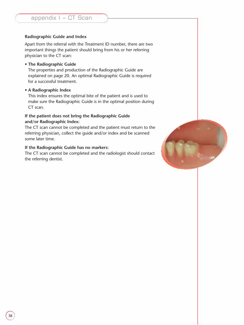
Radiographic Guide and Index
Apart from the referral with the Treatment ID number, there are twoimportant things the patient should bring from his or her referringphysician to the CT scan:
• The Radiographic GuideThe properties and production of the Radiographic Guide areexplained on page 20. An optimal Radiographic Guide is requiredfor a successful treatment.
• A Radiographic IndexThis index ensures the optimal bite of the patient and is used tomake sure the Radiographic Guide is in the optimal position duringCT scan.
If the patient does not bring the Radiographic Guide and/or Radiographic Index:The CT scan cannot be completed and the patient must return to thereferring physician, collect the guide and/or index and be scannedsome later time.
If the Radiographic Guide has no markers:The CT scan cannot be completed and the radiologist should contactthe referring dentist.
appendix I – CT Scan

39
CT Scan Protocol
First Scan
The first CT scan in the procedure is a scan of the patient wearing theprepared Radiographic Guide and the Radiographic Index.
The following routine is recommended:
• Position the patient in the CT scan with the Radiographic Guide inthe proper edentulous place in the mouth.
In single and partially edentulous cases: There should be holes, or“inspection windows”, drilled on the radiographic guide to verify thecorrect position over the remaining teeth.
• Ask the patient to lean his or her head forward with the chin closeto the chest, while remaining comfortable.
• Make sure that the patient is positioned with the occlusal plane andthe horizontal laser indicator parallel and coinciding (if the CT scanhas a vertical laser indicator, this should be positioned between thecentral incisors). No gantry tilt is allowed.
In single and partially edentulous cases: When the patient hasmetal restorations on his or her remaining teeth, they may create dis-turbing artifacts on the CT scans. Try to position the patient so thatmost of the field of interest of the axial slices through the radiographicguide avoids passing through the metal restorations.
• The patient should be advised to remain very still during the wholescanning process, and avoid swallowing.
• Choose the correct distance between the axial slices, with a recommended maximum distance of 0.5 mm.
appendix I – CT Scan

40
• When the “scout image” is shown on the screen, correction of theposition of the patient should be done to a horizontal position ofthe hard palate. Then the field of interest for axial slices, parallelwith the horizontally positioned hard palate, can be assigned.
In single and partially edentulous cases:The “scout image” point above applies to the upper jaw. For the lowerjaw, either the occlusal plane, if enough teeth remain, or the alveolarcrest, alternatively the middle part of the basis mandibule around thepre-molar region will be horizontally positioned giving almost hori-zontal axial slices in the field of interest. No gantry tilt is allowed.
• Insert the Radiographic Index in the correct position between theRadiographic Guide and the opposing teeth. It is very importantthat the patient bites firmly on the index and Radiographic Guideduring the scanning, to align the guide well to the soft tissue of thepatient eliminating any potential air pockets.
Note: The patient should not bite so hard that the Radiographic Guidedeforms in any way.
• Check that the position of the patient remains stable, and start scanning.
appendix I – CT Scan

41
Second Scan
• After the first CT scan, allow the patient to leave the scanner andremove the Radiographic Guide from his or her mouth in order toscan the guide alone, without the index.
• The Radiographic Guide should be scanned in a similar position asthe patient scan. Therefore, attach the guide to a suitable object ofradiolucent material and position it in the CT scanner, as close topossible as it was located in the patient’s mouth during the first scan.
Note! The positioning of the Radiographic Guide is only important for agood orientation. An accurate final match is performed during pre-processing of the data using the Procera® Software Planning Program – Surgical data, based on the gutta percha-markers.
• The material used to properly position the Radiographic Guide should be as radiolucent as possible. Make sure that the material issignificantly darker after scanning than the Radiographic Guide.Paper boxes or other head-sized objects made of polyethylene andpolyurethane-foam materials are suitable. Use adhesive tape toattach the Radiographic Guide to the material, such as Leukoflex,Leukosilk (BSNmedical); or Nexcare paper tape series, Duraporetapes (3M).
• Apply the same CT settings for the second scan used for the firstscan, including the same distance of the axial slices.
• Start scanning.
Data Transfer of CT Data once the double-scan is completed andthe Radiographic Guide and Radiographic Index have been returnedto the patient, transfer the CT data to the dentist in the uncompressedDICOM 3 format for pre-processing.
Important! It is the responsibility of the surgeon, or the radiologist, togenerate CT images of optimal quality according to the standard routineof programs available for each specific device, at as low a radiation dose as possible.
appendix I – CT Scan

42
appendix I – CT Scan
Generic CT protocol
Single slice CT scanner
Scan settings
• Spiral CT
• No gantry tilt
• Tube voltage: 120 kV
• Effective tube current: 100 mAs
• Collimation: 1 mm
• Table speed: 1 mm/rotation
• Gantry rotation speed: 1 rotation/s
Reconstruction settings
• Reconstruction interval is 0.5 mm.
• Reconstruction kernel: a sharp bone filter is preferred
Multi-slice CT scanner
Scan settings
• Spiral CT
• No gantry tilt
• Tube voltage: 120 kV
• Effective tube current: 90 mAs
• Collimation equals (number of detectors ×) smallest detector width
• Feed /rotation is set equal to collimation × 0.7
• Gantry rotation speed is about 0.75 seconds for one rotation
Reconstruction settings
• Reconstruction interval is half detector width (typically: 0.3 mm or 0.5 mm)
• Reconstruction kernel: a sharp bone filter is preferred.
Cone-beam CT scanner
• The cone-beam CT scanners are dedicated for imaging the skull. Follow the manufacturer’sinstructions to scan a jaw for oral implant planning.The side of a cubic voxel should be within the range of 0.3 – 0.5 mm.
• During reconstruction, no tilting of the axial slices is allowed.
43
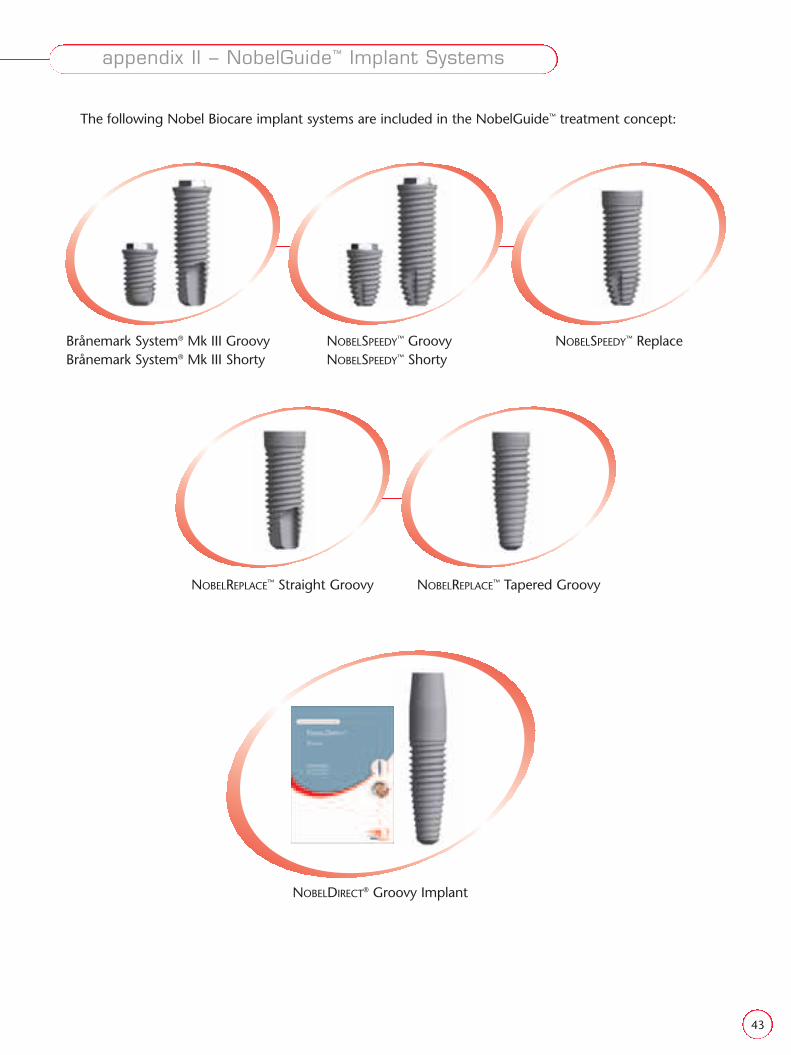
NOBELREPLACE™ Straight Groovy NOBELREPLACE™ Tapered Groovy
NOBELDIRECT® Groovy Implant
The following Nobel Biocare implant systems are included in the NobelGuide™ treatment concept:
Brånemark System® Mk III GroovyBrånemark System® Mk III Shorty
NOBELSPEEDY™ GroovyNOBELSPEEDY™ Shorty
NOBELSPEEDY™ Replace
appendix II – NobelGuide™ Implant Systems

44
Procera® Software(for Computer-Based Planning)
15400 Procera® Software Clinical Design Pro*15401 Procera® Software Clinical Design Premium*15402 Procera® Software Clinical Premium upgrade15403 Procera® Software Premium Suite*15849 Procera® Software Clinical Design – Add-on Licence16113 Procera® Software Clinical Premium for Lab* (for Procera® Lab)* Please note that the Procera® Software requires an annual licence fee which
is included the first year.15653 Procera® Software CT Conversion
Surgical Templates(to be ordered in Procera® Software Clinical Design Pro or Premium)
14750 Finished Surgical Template 5 implants and more15404 Finished Surgical Template 2–4 implants15405 Finished Surgical Template 1 implant14751 Duplicate Denture
NobelGuide™ Surgical Kits32306 Brånemark System® Guided Surgery Kit
Kit includes products for RP-platformNote! Instruments for np and wp need to be ordered separately.
32320 Brånemark System® Guided Surgery Kit Box 30909 Guided Anchor Pin ∅ 1.5 mm32110 Brånemark System® Manual Torque Wrench Surgical29167 Manual Torque Wrench Adapter Prosthetic32865 Guided Implant Mount Bmk Syst RP
32804 Guided Template Abutment w Screw Bmk Syst RP
29081 Connection to handpiece29149 Screwdriver Manual Unigrip™ 28 mm29151 Screwdriver Machine Unigrip™ 20 mm
32797 Guided Drill Guide Kit Box32813 Handle for Guided Drill Guide32815 Guided Drill Guide RP to ∅ 2 mm32818 Guided Drill Guide RP to ∅ 2.8 mm32820 Guided Drill Guide RP to ∅ 3 mm32822 Guided Drill Guide RP to ∅ 3.2 mm32823 Guided Drill Guide RP to ∅ 3.4 mm29543 Implant sleeve holder33132 Brånemark System® Guided Surgery Wall chart
32954 NOBELREPLACE™ Tapered Guided Surgery KitIncludes instruments for NP and RP Implants.Note! Instruments for wp and 6.0 need to be ordered separately
32955 NobelReplace™ Tapered Guided Surgery Kit Box 30909 Guided Anchor Pin ∆ 1.5 mm32827 Guided Drill Tapered NP 3.5 × (+) 8 mm32828 Guided Drill Tapered NP 3.5 × (+) 10 mm32829 Guided Drill Tapered NP 3.5 × (+) 13 mm32830 Guided Drill Tapered NP 3.5 × (+) 16 mm32831 Guided Drill Tapered RP 4.3 × (+) 8 mm32832 Guided Drill Tapered RP 4.3 × (+) 10 mm32833 Guided Drill Tapered RP 4.3 × (+) 13 mm32834 Guided Drill Tapered RP 4.3 × (+) 16 mm29167 Manual Torque Wrench Adapter Prosthetic
product catalog
45
32856 Guided Screw Tap Tapered NP
32858 Guided Screw Tap Tapered RP
33065 NobelReplace™ Connection to Handpiece29149 Screwdriver Manual Unigrip™ 28 mm29151 Screwdriver Machine Unigrip™ 20 mm32844 Guided Dense Bone Drill Tapered NP 3.5 × 13 mm32845 Guided Dense Bone Drill Tapered NP 3.5 × 16 mm32847 Guided Dense Bone Drill Tapered RP 4.3 × 13 mm32848 Guided Dense Bone Drill Tapered RP 4.3 × 16 mm
32957 Guided Drill Guide Tapered Kit Box32813 Handle for Guided Drill Guide32814 Guided Drill Guide NP to ∅ 2 mm32815 Guided Drill Guide RP to ∅ 2 mm33018 Guided Drill Guide Tapered RP to NP
32864 Guided Implant Mount NobRpl NP
32866 Guided Implant Mount NobRpl RP
32803 Guided Template Abutment w Screw NobRpl NP
32805 Guided Template Abutment w Screw NobRpl RP
29543 Implant Sleeve Holder33134 NobelReplace™ Tapered Guided Surgery Wall chart
32794 NobelReplace™ Straight Guided Surgery KitIncludes instruments for RP Implants.Note! Instruments for NP, WP and 6.0 need to be ordered separately
32796 NobelReplace™ Straight Guided Surgery Kit Box30909 Guide Anchor Pin ∅ 1.5 mm29167 Manual Torque Wrench Adapter Prosthetic32866 Guided Implant Mount NobRpl RP
32805 Guided Template Abutment w Screw NobRpl RP
33065 NobelReplace™ Connection to handpiece29149 Screwdriver Manual Unigrip™ 28 mm29151 Screwdriver Machine Unigrip™ 20 mm
32797 Guided Drill Guide Kit Box 32813 Handle for Guided Drill Guide32815 Guided Drill Guide RP to ∅ 2 mm32818 Guided Drill Guide RP to ∅ 2.8 mm32820 Guided Drill Guide RP to ∅ 3 mm32822 Guided Drill Guide RP to ∅ 3.2 mm32823 Guided Drill Guide RP to ∅ 3.4 mm29543 Implant sleeve holder33133 NobelReplace™ Straight Guided Surgery Wall chart
Drill Stops33085 Guided Drill Stop Kit
Included in kit:33086 Guided Drill Stop Kit Box33063 Drill Stop ∅ 233064 Drill Stop ∅ 2.833075 Drill Stop ∅ 333077 Drill Stop ∅ 3.233078 Drill Stop ∅ 3.433080 Drill Stop ∅ 3.833081 Drill Stop ∅ 4.2
product catalog

46
product catalog
Manuals15684 GB Procedures & Products NobelGuide™ NOBELSPEEDY™ Groovy
15691 GB Procedures & Products NobelGuide™ NOBELSPEEDY™ Replace
15699 GB Procedures & Products NobelGuide™ NOBELREPLACE™ Straight
15706 GB Procedures & Products NobelGuide™ NOBELREPLACE™ Tapered
15713 GB Procedures & Products NobelGuide™ Brånemark System®
15662 GB Procedures & Products NobelGuide™ NOBELDIRECT®
Lab Components32754 Guided Sleeve NP
32765 Guided Sleeve RP
32766 Guided Sleeve 6.0/WP
30909 Guided Anchor Pin ∅ 1.5mm
30908 Guided Anchor Pin Sleeve ∅ 1.5mm 3/pkg
32873 Guided Ti Temporary Coping NP
32874 Guided Ti Temporary Coping RP
32876 Guided Ti Temporary Coping 6.0/WP
15-1026 Procera® Implant Bridge Teeth-in-an-Hour™ NP
15-1027 Procera® Implant Bridge Teeth-in-an-Hour™ RP
15-1028 Procera® Implant Bridge Teeth-in-an-Hour™ 6.0/WP
Lab Components Brånemark System®
32768 Guided Cylinder w Pin Unigrip™ Bmk Syst NP
32770 Guided Cylinder w Pin Unigrip™ Bmk Syst RP
32774 Guided Cylinder w Pin Unigrip™ Bmk Syst WP
32879 Guided Pin 28 mm Bmk Syst NP
32881 Guided Pin 28 mm Bmk Syst RP
32884 Guided Pin 28 mm Bmk Syst WP
32887 Guided Laboratory Screw Bmk Syst NP
32889 Guided Laboratory Screw Bmk Syst RP
32892 Guided Laboratory Screw Bmk Syst WP
32895 Guided Laboratory Abutment Bmk Syst NP
32897 Guided Laboratory Abutment Bmk Syst RP
32899 Guided Laboratory Abutment Bmk Syst WP
32903 Guided Abutment Bmk Syst NP
32905 Guided Abutment Bmk Syst RP
32907 Guided Abutment Bmk Syst WP

47
product catalog
Lab Components NOBELREPLACE™
32769 Guided Cylinder w Pin Unigrip™ NobRpl NP
32771 Guided Cylinder w Pin Unigrip™ NobRpl RP
32775 Guided Cylinder w Pin Unigrip™ NobRpl WP
32778 Guided Cylinder w Pin Unigrip™ NobRpl 6.0
32880 Guided Pin 28mm NobRpl NP
32882 Guided Pin 28mm NobRpl RP
32885 Guided Pin 28mm NobRpl WP/6.0
32888 Guided Laboratory Screw NobRpl NP
32890 Guided Laboratory Screw NobRpl RP
32893 Guided Laboratory Screw NobRpl WP/6.0
32896 Guided Laboratory Abutment NobRpl NP
32898 Guided Laboratory Abutment NobRpl RP
32900 Guided Laboratory Abutment NobRpl WP
32902 Guided Laboratory Abutment NobRpl 6.0
32904 Guided Abutment NobRpl NP
32906 Guided Abutment NobRpl RP
32908 Guided Abutment NobRpl WP
32910 Guided Abutment NobRpl 6.0

48
reference guide
Description Article # Page
AAbutment
Guided Abutment NobRpl NP . . . . . . . . . . . . . . . . . . . . . . . .32904 .16,32,35,36,48,49Guided Abutment NobRpl RP . . . . . . . . . . . . . . . . . . . . . .32906 .16,32,35,36,48,49Guided Abutment NobRpl WP . . . . . . . . . . . . . . . . . . . . . .32908 .16,32,35,36,48,49Guided Abutment NobRpl 6.0 . . . . . . . . . . . . . . . . . . . . .32910 .16,32,35,36,48,49
Guided Abutment Bmk Syst NP . . . . . . . . . . . . . . . . . . . . .32903 . . .16,32,35,36,48Guided Abutment Bmk Syst RP . . . . . . . . . . . . . . . . . . . . .32905 . . .16,32,35,36,48Guided Abutment Bmk Syst WP . . . . . . . . . . . . . . . . . . . . .32907 . . .16,32,35,36,48
Anchor PinGuided Anchor Pin ∅1.5mm . . . . . . . . . . . . . . . . . . . . . . .30909 . . . . . .20,21,46,48Guided Anchor Pin Sleeve ∅1.5mm 3/pkg . . . . . . . . . . . .30908 . . . . . . . . . . . . .46
CConnection to handpiece
Connection to handpiece . . . . . . . . . . . . . . . . . . . . . . . . .29081 . . . . . . . . . . .46,47Connection to Handpiece NOBELREPLACE™ . . . . . . . . . . . . . .33065 . . . . . . . . . . .46,47
DDrills
Guided Drill Tapered NP 3.5×(+)8mm . . . . . . . . . . . . . . . .32827 . . . . . . . . . . . . .46Guided Drill Tapered NP 3.5×(+)10mm . . . . . . . . . . . . . . .32828 . . . . . . . . . . . . .46Guided Drill Tapered NP 3.5×(+)13mm . . . . . . . . . . . . . . .32829 . . . . . . . . . . . . .46Guided Drill Tapered NP 3.5×(+)16mm . . . . . . . . . . . . . . .32830 . . . . . . . . . . . . .46Guided Drill Tapered RP 4.3×(+)8mm . . . . . . . . . . . . . . . .32831 . . . . . . . . . . . . .46Guided Drill Tapered RP 4.3×(+)10mm . . . . . . . . . . . . . . .32832 . . . . . . . . . . . . .46Guided Drill Tapered RP 4.3×(+)13mm . . . . . . . . . . . . . . .32833 . . . . . . . . . . . . .46Guided Drill Tapered RP 4.3×(+)16mm . . . . . . . . . . . . . . .32834 . . . . . . . . . . . . .46
Guided Dense Bone Drill Tapered NP 3.5×13mm . . . . . . . .32844 . . . . . . . . . . .46,47Guided Dense Bone Drill Tapered NP 3.5×16mm . . . . . . . .32845 . . . . . . . . . . .46,47Guided Dense Bone Drill Tapered RP 4.3×13mm . . . . . . . .32847 . . . . . . . . . . .46,47Guided Dense Bone Drill Tapered RP 4.3×16mm . . . . . . . .32848 . . . . . . . . . . .46,47
Drill GuidesGuided Drill Guide rp to ∅2mm . . . . . . . . . . . . . . . . . . . .32815 . . . . . . . . . . .46,47Guided Drill Guide RP to ∅2.8mm . . . . . . . . . . . . . . . . . . .32818 . . . . . . . . . . .46,47Guided Drill Guide RP to ∅3mm . . . . . . . . . . . . . . . . . . . .32820 . . . . . . . . . . .46,47Guided Drill Guide RP to ∅3.2mm . . . . . . . . . . . . . . . . . . .32822 . . . . . . . . . . .46,47Guided Drill Guide RP to ∅3.4mm . . . . . . . . . . . . . . . . . . .32823 . . . . . . . . . . .46,47Guided Drill Guide NP to ∅2mm . . . . . . . . . . . . . . . . . . . .32814 . . . . . . . . . . .46,47Guided Drill Guide Tapered RP to NP . . . . . . . . . . . . . . . . .33018 . . . . . . . . . . . . .47
GGuided Cylinder
Guided Cylinder w Pin Unigrip™ NobRpl NP . . . . . . . . . . . .32769 . . . . . . . . . . . . .49Guided Cylinder w Pin Unigrip™ NobRpl RP . . . . . . . . . . . .32771 . . . . . . . . . . . . .49Guided Cylinder w Pin Unigrip™ NobRpl WP . . . . . . . . . . .32775 . . . . . . . . . . . . .49Guided Cylinder w Pin Unigrip™ NobRpl 6.0 . . . . . . . . . . .32778 . . . . . . . . . . . . .49
Guided Cylinder w Pin Unigrip™ Bmk Syst NP . . . . . . . . . .32768 . . . . . . . . . . . . .48Guided Cylinder w Pin Unigrip™ Bmk Syst RP . . . . . . . . . . .32770 . . . . . . . . . . . . .48Guided Cylinder w Pin Unigrip™ Bmk Syst WP . . . . . . . . . .32774 . . . . . . . . . . . . .48
Guided Drill Stop Kit . . . . . . . . . . . . . . . . . . . . . . . . . . . . .33085 . . . . . . . . . . . .3,47Guided Drill Stop Kit Box . . . . . . . . . . . . . . . . . . . . . . . . .33086 . . . . . . . . . . . . .47Drill Stop ∅2 . . . . . . . . . . . . . . . . . . . . . . . . . . . . . . . . . . .33063 . . . . . . . . . . . . .47Drill Stop ∅2.8 . . . . . . . . . . . . . . . . . . . . . . . . . . . . . . . . .33064 . . . . . . . . . . . . .47Drill Stop ∅3 . . . . . . . . . . . . . . . . . . . . . . . . . . . . . . . . . . .33075 . . . . . . . . . . . . .47Drill Stop ∅3.2 . . . . . . . . . . . . . . . . . . . . . . . . . . . . . . . . .33077 . . . . . . . . . . . . .47Drill Stop ∅3.4 . . . . . . . . . . . . . . . . . . . . . . . . . . . . . . . . .33078 . . . . . . . . . . . . .47Drill Stop ∅3.8 . . . . . . . . . . . . . . . . . . . . . . . . . . . . . . . . .33080 . . . . . . . . . . . . .47Drill Stop ∅4.2 . . . . . . . . . . . . . . . . . . . . . . . . . . . . . . . . .33081 . . . . . . . . . . . . .47
Guided PinGuided Pin 28mm NobRpl NP . . . . . . . . . . . . . . . . . . . . . .32880 . . . . . . . . . . . . .49Guided Pin 28mm NobRpl RP . . . . . . . . . . . . . . . . . . . . . .32882 . . . . . . . . . . . . .49Guided Pin 28mm NobRpl WP/6.0 . . . . . . . . . . . . . . . . . . .32885 . . . . . . . . . . . . .49
Guided Pin 28mm Bmk Syst NP . . . . . . . . . . . . . . . . . . . . .32879 . . . . . . . . . . . . .48Guided Pin 28mm Bmk Syst RP . . . . . . . . . . . . . . . . . . . . .32881 . . . . . . . . . . . . .48Guided Pin 28mm Bmk Syst WP . . . . . . . . . . . . . . . . . . . . .32884 . . . . . . . . . . . . .48
Guided SleeveGuided Sleeve NP . . . . . . . . . . . . . . . . . . . . . . . . . . . . . . .32754 . . . . . .15,27,29,48
Guided Sleeve RP . . . . . . . . . . . . . . . . . . . . . . . . . . . . . . . .32765 . . . . . .15,27,29,48Guided Sleeve 6.0/WP . . . . . . . . . . . . . . . . . . . . . . . . . . . .32766 . . . . . .15,27,29,48
H
Handle for Guided Drill Guide . . . . . . . . . . . . . . . . . . . . . .32813 . . . . . . . . . . .46,47
IImplant Mount
Guided Implant Mount Bmk Syst RP . . . . . . . . . . . . . . . . .32865 . . . . . . . . . . .46,47Guided Implant Mount NobRpl NP . . . . . . . . . . . . . . . . . .32864 . . . . . . . . . . .46,47Guided Implant Mount NobRpl RP . . . . . . . . . . . . . . . . . .32866 . . . . . . . . . . .46,47
Implant sleeve holder . . . . . . . . . . . . . . . . . . . . . . . . . . . . .29543 . . . . . . . . . . .46,47
KKits
Brånemark System® Guided Surgery Kit . . . . . . . . . . . . . .32306 . . . . . . . . . . . .3,46Brånemark System® Guided Surgery Kit Box . . . . . . . . . . .32320 . . . . . . . . . . . . .46Guided Drill Guide Kit Box . . . . . . . . . . . . . . . . . . . . . . . .32797 . . . . . . . . . . .46,47NOBELREPLACE™ Tapered Guided Surgery Kit . . . . . . . . . . . .32954 . . . . . . . . . . . .3,46NOBELREPLACE™ Tapered Guided Surgery Kit Box . . . . . . . .32955 . . . . . . . . . . . . .46NOBELREPLACE™ Straight Guided Surgery Kit . . . . . . . . . . . .32794 . . . . . . . . . . . .3,47NOBELREPLACE™ Straight Guided Surgery Kit Box . . . . . . . . .32796 . . . . . . . . . . . . .47Guided Drill Guide Tapered Kit Box . . . . . . . . . . . . . . . . . .32957 . . . . . . . . . . . . .47
LLaboratory Abutment
Guided Laboratory Abutment NobRpl NP . . . . . . . . . . . . .32896 . . . . . . . . . . . . .49Guided Laboratory Abutment NobRpl RP . . . . . . . . . . . . . .32898 . . . . . . . . . . . . .49Guided Laboratory Abutment NobRpl WP . . . . . . . . . . . . .32900 . . . . . . . . . . . . .49Guided Laboratory Abutment NobRpl 6.0 . . . . . . . . . . . . .32902 . . . . . . . . . . . . .49
Guided Laboratory Abutment Bmk Syst NP . . . . . . . . . . . .32895 . . . . . . . . . . . . .48Guided Laboratory Abutment Bmk Syst RP . . . . . . . . . . . .32897 . . . . . . . . . . . . .48Guided Laboratory Abutment Bmk Syst WP . . . . . . . . . . . .32899 . . . . . . . . . . . . .48
Laboratory ScrewGuided Laboratory Screw NobRpl NP . . . . . . . . . . . . . . . .32888 . . . . . . . . . . . . .49Guided Laboratory Screw NobRpl RP . . . . . . . . . . . . . . . . .32890 . . . . . . . . . . . . .49Guided Laboratory Screw NobRpl WP/6.0 . . . . . . . . . . . . .32893 . . . . . . . . . . . . .49
Guided Laboratory Screw Bmk Syst NP . . . . . . . . . . . . . . .32887 . . . . . . . . . . . . .48Guided Laboratory Screw Bmk Syst RP . . . . . . . . . . . . . . . .32889 . . . . . . . . . . . . .48Guided Laboratory Screw Bmk Syst WP . . . . . . . . . . . . . . .32892 . . . . . . . . . . . . .48
MManual Torque Wrench
Brånemark System® Manual Torque Wrench Surgical . . . .32110 . . . . . . . . . . . . .46Manual Torque Wrench Adapter Prosthetic . . . . . . . . . . . .29167 . . . . . . . . . . .46,47
ManualsGS NOBELSPEEDY™ Groovy . . . . . . . . . . . . . . . . . . . . . . . . . .15684 GB . . . . . . . . . .48GS NOBELSPEEDY™ Replace . . . . . . . . . . . . . . . . . . . . . . . . . .15691 GB . . . . . . . . . .48GS NOBELREPLACE™ Straight . . . . . . . . . . . . . . . . . . . . . . . . .15699 GB . . . . . . . . . .48GS NOBELREPLACE™ Tapered . . . . . . . . . . . . . . . . . . . . . . . . .15706 GB . . . . . . . . . .48GS Brånemark System® Mk III . . . . . . . . . . . . . . . . . . . . . .15713 GB . . . . . . . . . .48GS NOBELDIRECT® . . . . . . . . . . . . . . . . . . . . . . . . . . . . . . . .15662 GB . . . . . . . . . .48
PProcera® Implant Bridge
Procera® Implant Bridge Teeth-in-an-Hour™ NP . . . . . . . . . .15-1026 . . . . . . .35,36,48Procera® Implant Bridge Teeth-in-an-Hour™ RP . . . . . . . . . .15-1027 . . . . . . .35,36,48Procera® Implant Bridge Teeth-in-an-Hour™ 6.0/WP . . . . . .15-1028 . . . . . . .35,36,48
S
ScrewdriverScrewdriver Manual Unigrip™ 28 mm . . . . . . . . . . . . . . . .29149 . . .15,28,32,46,47Screwdriver Machine Unigrip™ 20 mm . . . . . . . . . . . . . . .29151 . . . . . . . . . . .46,47
Screw TapsGuided Screw Tap Tapered NP . . . . . . . . . . . . . . . . . . . . . .32856 . . . . . . . . . . .46,47Guided Screw Tap Tapered RP . . . . . . . . . . . . . . . . . . . . . .32858 . . . . . . . . . . .46,47
SoftwareProcera® Software Manager . . . . . . . . . . . . . . . . . . . . . . . .33145 . . . . . . . . . . . . .46Procera® Software Clinical Design Pro . . . . . . . . . . . . . . . .15400 . . . . . . . . .3,24,46Procera® Software Clinical Design Premium . . . . . . . . . . . .15401 . . . . . . . . .3,24,46Procera® Software Clinical Premium upgrade . . . . . . . . . .15402 . . . . . . . . . . . . .46Procera® Software Premium Suite . . . . . . . . . . . . . . . . . . .15403 . . . . . . . . . . . . .46
Index in Alphabetical order

49
TTemplate Abutment
Guided Template Abutment w Screw Bmk Syst RP . . . . . . .32804 . . . . . . . . . . . . .46Guided Template Abutment w Screw NobRpl NP . . . . . . .32803 . . . . . . . . . . . . .47Guided Template Abutment w Screw NobRpl RP . . . . . . . .32805 . . . . . . . . . . . . .47
Ti Temporary CopingGuided Ti Temporary Coping NP . . . . . . . . . . . . . . . . . . . .32873 . . . . . . . . . . .32,48Guided Ti Temporary Coping RP . . . . . . . . . . . . . . . . . . . .32874 . . . . . . . . . . .32,48Guided Ti Temporary Coping 6.0/WP . . . . . . . . . . . . . . . . .32876 . . . . . . . . . . .32,48
W
WallchartsBrånemark System® Guided Surgery Wall chart . . . . . . . . .33132 . . . . . . . . . . . . .46NOBELREPLACE™ Tapered Guided Surgery Wall chart . . . . . . .33134 . . . . . . . . . . . . .47NOBELREPLACE™ Straight Guided Surgery Wall chart . . . . . . .33133 . . . . . . . . . . . . .47
reference guide

50
reference guide
15400 . . . . .Procera® Software Clinical Design Pro . . . . . . . . . . . . . . . . . . . . . .3,24,4615401 . . . . .Procera® Software Clinical Design Premium . . . . . . . . . . . . . . . . .3,24,4615402 . . . . .Procera® Software Clinical Premium upgrade . . . . . . . . . . . . . . . . . . . .4615403 . . . . .Procera® Software Premium Suite . . . . . . . . . . . . . . . . . . . . . . . . . . . . .4629081 . . . . .Connection to handpiece . . . . . . . . . . . . . . . . . . . . . . . . . . . . . . . . . . .4629149 . . . . .Screwdriver Manual Unigrip™ 28mm . . . . . . . . . . . . . . . .15,28,32,46,4729151 . . . . .Screwdriver Machine Unigrip™ 20mm . . . . . . . . . . . . . . . . . . . . . . .46,4729167 . . . . .Manual Torque Wrench Adapter Prosthetic . . . . . . . . . . . . . . . . . . .46,4729543 . . . . .Implant sleeve holder . . . . . . . . . . . . . . . . . . . . . . . . . . . . . . . . . . .46,4730908 . . . . .Guided Anchor Pin Sleeve ∅1.5mm 3/pkg . . . . . . . . . . . . . . . . . . . . . .4630909 . . . . .Guided Anchor Pin ∅1.5mm . . . . . . . . . . . . . . . . . . . . . . . . . . .20,21,4632110 . . . . .Brånemark System® Manual Torque Wrench Surgical . . . . . . . . . . . . . .4632306 . . . . .Brånemark System® Guided Surgery Kit . . . . . . . . . . . . . . . . . . . . . .4,4632320 . . . . .Brånemark System® Guided Surgery Kit Box . . . . . . . . . . . . . . . . . . . .4632754 . . . . .Guided Sleeve NP . . . . . . . . . . . . . . . . . . . . . . . . . . . . . . . . . .15,27,29,4832765 . . . . .Guided Sleeve RP . . . . . . . . . . . . . . . . . . . . . . . . . . . . . . . . . .15,27,29,4832766 . . . . .Guided Sleeve 6.0/WP . . . . . . . . . . . . . . . . . . . . . . . . . . . . . .15,27,29,4832768 . . . . .Guided Cylinder w Pin Unigrip™ Bmk Syst NP . . . . . . . . . . . . . . . . . . . .4832769 . . . . .Guided Cylinder w Pin Unigrip™ NobRpl NP . . . . . . . . . . . . . . . . . . . . .4932770 . . . . .Guided Cylinder w Pin Unigrip™ Bmk Syst RP . . . . . . . . . . . . . . . . . . . .4832771 . . . . .Guided Cylinder w Pin Unigrip™ NobRpl RP . . . . . . . . . . . . . . . . . . . . . .4932774 . . . . .Guided Cylinder w Pin Unigrip™ Bmk Syst WP . . . . . . . . . . . . . . . . . . . .4832775 . . . . .Guided Cylinder w Pin Unigrip™ NobRpl WP . . . . . . . . . . . . . . . . . . . . .4932778 . . . . .Guided Cylinder w Pin Unigrip™ NobRpl 6.0 . . . . . . . . . . . . . . . . . . . . .4932794 . . . . .NOBELREPLACE™ Straight Guided Surgery Kit . . . . . . . . . . . . . . . . . . . . .3,4732796 . . . . .NOBELREPLACE™ Straight Guided Surgery Kit Box . . . . . . . . . . . . . . . . . . .4732797 . . . . .Guided Drill Guide Kit Box . . . . . . . . . . . . . . . . . . . . . . . . . . . . . . . .46,4732803 . . . . .Guided Template Abutment w Screw NobRpl NP . . . . . . . . . . . . . . . . .4732804 . . . . .Guided Template Abutment w Screw Bmk Syst RP . . . . . . . . . . . . . . . .4632805 . . . . .Guided Template Abutment w Screw NobRpl RP . . . . . . . . . . . . . . . . . .4532813 . . . . .Handle for Guided Drill Guide . . . . . . . . . . . . . . . . . . . . . . . . . . . . .46,4732814 . . . . .Guided Drill Guide NP to ∅2mm . . . . . . . . . . . . . . . . . . . . . . . . . . .46,4732815 . . . . .Guided Drill Guide RP to ∅2mm . . . . . . . . . . . . . . . . . . . . . . . . . . .46,4732818 . . . . .Guided Drill Guide RP to ∅2.8mm . . . . . . . . . . . . . . . . . . . . . . . . . .46,4732820 . . . . .Guided Drill Guide RP to ∅3mm . . . . . . . . . . . . . . . . . . . . . . . . . . .46,4732822 . . . . .Guided Drill Guide RP to ∅3.2mm . . . . . . . . . . . . . . . . . . . . . . . . . .46,4732823 . . . . .Guided Drill Guide RP to ∅3.4mm . . . . . . . . . . . . . . . . . . . . . . . . . .46,4732827 . . . . .Guided Drill Tapered NP 3.5×(+)8mm . . . . . . . . . . . . . . . . . . . . . . . . . .4632828 . . . . .Guided Drill Tapered NP 3.5×(+)10mm . . . . . . . . . . . . . . . . . . . . . . . . .4632829 . . . . .Guided Drill Tapered NP 3.5×(+)13mm . . . . . . . . . . . . . . . . . . . . . . . . .4632830 . . . . .Guided Drill Tapered NP 3.5×(+)16mm . . . . . . . . . . . . . . . . . . . . . . . . .4632831 . . . . .Guided Drill Tapered RP 4.3×(+)8mm . . . . . . . . . . . . . . . . . . . . . . . . . .4632832 . . . . .Guided Drill Tapered RP 4.3×(+)10mm . . . . . . . . . . . . . . . . . . . . . . . . .4632833 . . . . .Guided Drill Tapered RP 4.3×(+)13mm . . . . . . . . . . . . . . . . . . . . . . . . .4632834 . . . . .Guided Drill Tapered RP 4.3×(+)16mm . . . . . . . . . . . . . . . . . . . . . . . . .4632844 . . . . .Guided Dense Bone Drill Tapered NP 3.5×13mm . . . . . . . . . . . . . . . . .4632845 . . . . .Guided Dense Bone Drill Tapered NP 3.5×16mm . . . . . . . . . . . . . . . . .4632847 . . . . .Guided Dense Bone Drill Tapered RP 4.3×13mm . . . . . . . . . . . . . . . . . .4632848 . . . . .Guided Dense Bone Drill Tapered RP 4.3×16mm . . . . . . . . . . . . . . . . . .4632856 . . . . .Guided Screw Tap Tapered NP . . . . . . . . . . . . . . . . . . . . . . . . . . . . . . .4632858 . . . . .Guided Screw Tap Tapered RP . . . . . . . . . . . . . . . . . . . . . . . . . . . . . . . .4632864 . . . . .Guided Implant Mount NobRpl NP . . . . . . . . . . . . . . . . . . . . . . . . .46,4732865 . . . . .Guided Implant Mount Bmk Syst RP . . . . . . . . . . . . . . . . . . . . . . . . .46,4732866 . . . . .Guided Implant Mount NobRpl RP . . . . . . . . . . . . . . . . . . . . . . . . . .46,4732873 . . . . .Guided Ti Temporary Coping NP . . . . . . . . . . . . . . . . . . . . . . . . . . .32,4832874 . . . . .Guided Ti Temporary Coping RP . . . . . . . . . . . . . . . . . . . . . . . . . . .32,4832876 . . . . .Guided Ti Temporary Coping 6.0/WP . . . . . . . . . . . . . . . . . . . . . . . .32,4832879 . . . . .Guided Pin 28mm Bmk Syst NP . . . . . . . . . . . . . . . . . . . . . . . . . . . . . . .4832880 . . . . .Guided Pin 28mm NobRpl NP . . . . . . . . . . . . . . . . . . . . . . . . . . . . . . . .4932881 . . . . .Guided Pin 28mm Bmk Syst RP . . . . . . . . . . . . . . . . . . . . . . . . . . . . . . .4832882 . . . . .Guided Pin 28mm NobRpl RP . . . . . . . . . . . . . . . . . . . . . . . . . . . . . . . .4932884 . . . . .Guided Pin 28mm Bmk Syst WP . . . . . . . . . . . . . . . . . . . . . . . . . . . . . .4832885 . . . . .Guided Pin 28mm NobRpl WP/6.0 . . . . . . . . . . . . . . . . . . . . . . . . . . . .4932887 . . . . .Guided Laboratory Screw Bmk Syst NP . . . . . . . . . . . . . . . . . . . . . . . . .4832888 . . . . .Guided Laboratory Screw NobRpl NP . . . . . . . . . . . . . . . . . . . . . . . . . .4932889 . . . . .Guided Laboratory Screw Bmk Syst RP . . . . . . . . . . . . . . . . . . . . . . . . .4832890 . . . . .Guided Laboratory Screw NobRpl RP . . . . . . . . . . . . . . . . . . . . . . . . . . .4932892 . . . . .Guided Laboratory Screw Bmk Syst WP . . . . . . . . . . . . . . . . . . . . . . . . .4832893 . . . . .Guided Laboratory Screw NobRpl WP/6.0 . . . . . . . . . . . . . . . . . . . . . . .4932895 . . . . .Guided Laboratory Abutment Bmk Syst NP . . . . . . . . . . . . . . . . . . . . . .4832896 . . . . .Guided Laboratory Abutment NobRpl NP . . . . . . . . . . . . . . . . . . . . . . .4932897 . . . . .Guided Laboratory Abutment Bmk Syst RP . . . . . . . . . . . . . . . . . . . . . .4832898 . . . . .Guided Laboratory Abutment NobRpl RP . . . . . . . . . . . . . . . . . . . . . . .4932899 . . . . .Guided Laboratory Abutment Bmk Syst WP . . . . . . . . . . . . . . . . . . . . . .4832900 . . . . .Guided Laboratory Abutment NobRpl WP . . . . . . . . . . . . . . . . . . . . . . .4932902 . . . . .Guided Laboratory Abutment NobRpl 6.0 . . . . . . . . . . . . . . . . . . . . . .4932903 . . . . .Guided Abutment Bmk Syst NP . . . . . . . . . . . . . . . . . . . . .16,32,35,36,4832904 . . . . .Guided Abutment NobRpl NP . . . . . . . . . . . . . . . . . . . . . .16,32,35,36,4932905 . . . . .Guided Abutment Bmk Syst RP . . . . . . . . . . . . . . . . . . . . .16,32,35,36,4832906 . . . . .Guided Abutment NobRpl RP . . . . . . . . . . . . . . . . . . . . . .16,32,35,36,4932907 . . . . .Guided Abutment Bmk Syst WP . . . . . . . . . . . . . . . . . . . . .16,32,35,36,4832908 . . . . .Guided Abutment NobRpl WP . . . . . . . . . . . . . . . . . . . . . .16,32,35,36,4932910 . . . . .Guided Abutment NobRpl 6.0 . . . . . . . . . . . . . . . . . . . . .16,32,35,36,4932954 . . . . .NOBELREPLACE™ Tapered Guided Surgery Kit . . . . . . . . . . . . . . . . . . . .3,4632955 . . . . .NOBELREPLACE™ Tapered Guided Surgery Kit Box . . . . . . . . . . . . . . . . . .4632957 . . . . .Guided Drill Guide Tapered Kit Box . . . . . . . . . . . . . . . . . . . . . . . . . . .4733018 . . . . .Guided Drill Guide Tapered RP to NP . . . . . . . . . . . . . . . . . . . . . . . . . . .47
33063 . . . . .Drill Stop ∅2 . . . . . . . . . . . . . . . . . . . . . . . . . . . . . . . . . . . . . . . . . . . .4733064 . . . . .Drill Stop ∅2.8 . . . . . . . . . . . . . . . . . . . . . . . . . . . . . . . . . . . . . . . . . . .4733065 . . . . .Connection to Handpiece NOBELREPLACE™ . . . . . . . . . . . . . . . . . . . . .46,4733075 . . . . .Drill Stop ∅3 . . . . . . . . . . . . . . . . . . . . . . . . . . . . . . . . . . . . . . . . . . . .4733077 . . . . .Drill Stop ∅3.2 . . . . . . . . . . . . . . . . . . . . . . . . . . . . . . . . . . . . . . . . . . .4733078 . . . . .Drill Stop ∅3.4 . . . . . . . . . . . . . . . . . . . . . . . . . . . . . . . . . . . . . . . . . . .4733080 . . . . .Drill Stop ∅3.8 . . . . . . . . . . . . . . . . . . . . . . . . . . . . . . . . . . . . . . . . . . .4733081 . . . . .Drill Stop ∅4.2 . . . . . . . . . . . . . . . . . . . . . . . . . . . . . . . . . . . . . . . . . . .4733085 . . . . .Guided Drill Stop Kit . . . . . . . . . . . . . . . . . . . . . . . . . . . . . . . . . . . . .3,4733086 . . . . .Guided Drill Stop Kit Box . . . . . . . . . . . . . . . . . . . . . . . . . . . . . . . . . . .4733132 . . . . .Brånemark System® Guided Surgery Wall chart . . . . . . . . . . . . . . . . . . .4633133 . . . . .NOBELREPLACE™ Straight Guided Surgery Wall chart . . . . . . . . . . . . . . . .4733134 . . . . .NOBELREPLACE™ Tapered Guided Surgery Wall chart . . . . . . . . . . . . . . . .4733145 . . . . .Procera® Software Manager . . . . . . . . . . . . . . . . . . . . . . . . . . . . . . . . .4615-1026 . . .Procera® Implant Bridge Teeth-in-an-Hour™ NP . . . . . . . . . . . . . .35,36,4815-1027 . . .Procera® Implant Bridge Teeth-in-an-Hour™ RP . . . . . . . . . . . . . . .35,36,4815-1028 . . .Procera® Implant Bridge Teeth-in-an-Hour™ 6.0/WP . . . . . . . . . . .35,36,4815662 GB . .GS NOBELDIRECT® . . . . . . . . . . . . . . . . . . . . . . . . . . . . . . . . . . . . . . . . . .4815684 GB . .GS NOBELSPEEDY™ Groovy . . . . . . . . . . . . . . . . . . . . . . . . . . . . . . . . . . . .4815691 GB . .GS NOBELSPEEDY™ Replace . . . . . . . . . . . . . . . . . . . . . . . . . . . . . . . . . . . .4815699 GB . .GS NOBELREPLACE™ Straight . . . . . . . . . . . . . . . . . . . . . . . . . . . . . . . . . . .4815706 GB . .GS NOBELREPLACE™ Tapered . . . . . . . . . . . . . . . . . . . . . . . . . . . . . . . . . . .4815713 GB . .GS Brånemark System® Mk III . . . . . . . . . . . . . . . . . . . . . . . . . . . . . . . .48
Index in article number order


www.nobelbiocare.com
our qualifications are
Nobel Biocare cares about the environment and all production units are certified according to Environmental Management System ISO 14001
your security
1616
1 Lo
t “G
B 05
10”
Prin
ted
in S
wed
en.
© N
obel
Bio
care
Ser
vice
s A
G,
2005
.N
obel
Bio
care
, th
e N
obel
Bio
care
logo
typ
e an
d al
l oth
er t
rade
mar
ks u
sed
in t
his
docu
men
t ar
e, if
not
hing
els
e is
sta
ted
or is
evi
dent
fro
m t
he c
onte
xt in
a c
erta
in c
ase,
tra
dem
arks
of
the
Nob
el B
ioca
re g
roup
.
Achievements
• Inheritors and developers of the work ofProfessor Brånemark – founder of modernimplantology. World leaders in the field
• Providers of the most comprehensive andflexible crown, bridge and implant solutionsin the world
• Creators of unique biocompatible materialTiUnite® for optimal osseointegration,Immediate Function™ and Soft TissueIntegration™
• Creators of CAD/CAM dentistry
• Creators of unique Procera® System –one seamless procedure from 3D planning tofully guided surgery right through to customizedceramic restoration
• FDA cleared for Immediate Function™
(except 3.0 and Zygoma)
• FDA cleared for Teeth-in-an-Hour™ in 2004
Quality
• Zero non-conformities in 2004 FDA inspectionof Nobel Biocare production units in Göteborg,Karlskoga and Stockholm
Research
• Formal collaboration with over 50 academicinstitutions and 600 independent scientistsaround the world
• More clinical studies on immediate or earlyloading than all other competitors combined(Medline Feb 2005)
• More prospective clinical studies with at least5-year follow-up than all other competitorscombined (Berglund et al 2002)
Support
• 165.000 customers trained by 1.985 dentalprofessionals in 37 countries and in 19 languages,during 2004
• Own sales organizations with local NobelBiocare staff in 29 countries
• Leading business website in 8 languages, withcomplete online service supplying all productsand at least 500 courses available at all times