concept generation and evaluation msd project 10662 multi camera system
Post on 19-Dec-2015
223 views
TRANSCRIPT

Concept Generation and Evaluation
MSD Project 10662Multi Camera System

Electrical System DesignThe over all system was designed to show a connector board which would take all the signal in and transfer them to the FPGA in the correct format to allow for expansion of the system.
2 Cameras through D3 protocol1 INS System 1 OEM Board1 FPGA Board 1 Internal Storage1 Wireless transfer

Detailed View of Switch to FPGAThe Camera is selected by a mux that is controled by the FPGA. This systems allowed for 1 D3 input connection to be run to the board. If more cameras wanted to be added then the Connector Board would have to be redesigned.
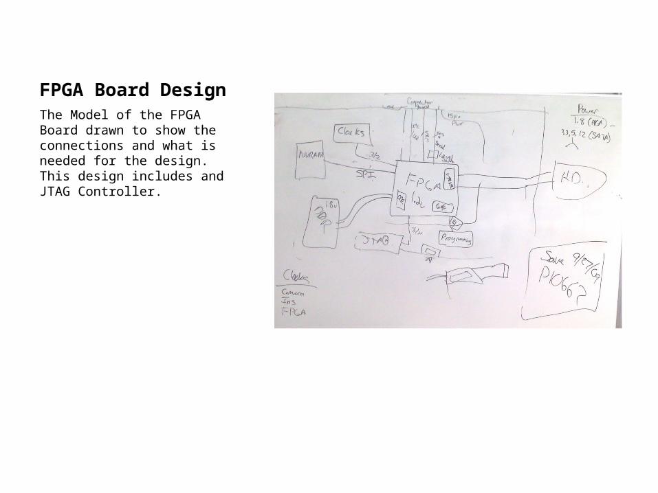
FPGA Board DesignThe Model of the FPGA Board drawn to show the connections and what is needed for the design. This design includes and JTAG Controller.

Mechanical DesignsDesign showing the mounting of design package to the airplane and how the boards would stack up.
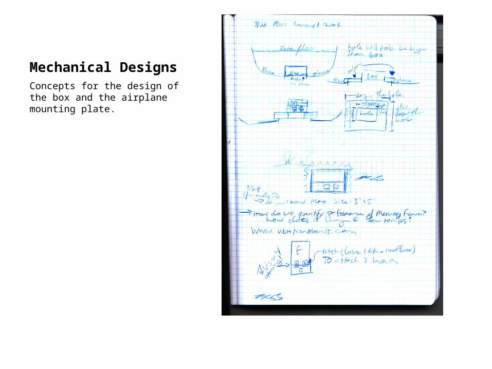
Mechanical DesignsConcepts for the design of the box and the airplane mounting plate.

Mechanical Designs The position of the boards are showing to minimize the size of the box and to include all boards and units in one enclosure.

Concept Improvement and Selection
MSD Project 10662Multi Camera System

System LayoutThe modified Design of the System Layout to better meet the needs of the customer. This Design was modified to include up to 6 cameras and corrected the errors found in the data paths.
2 GigE Cameras2 CameraLink Cameras2 D3 Cameras1 INS SystemSync System for external Controls1 Raw internal Storage1 OEM Board to include compressing and Transfer1 FPGA Board to include expansion header

FPGA Board DesignModified FPGA Board to include connections to the connector board and a modified layout to help with data transfer and speed.

Mechanical Board layoutPosition of the Electrical Enclosure to show the placement of the boards.
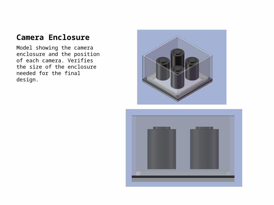
Camera EnclosureModel showing the camera enclosure and the position of each camera. Verifies the size of the enclosure needed for the final design.