concept generation using morphological and options matrices
TRANSCRIPT

Clemson UniversityTigerPrints
All Theses Theses
12-2012
Concept Generation Using Morphological AndOptions MatricesDani GeorgeClemson University, [email protected]
Follow this and additional works at: https://tigerprints.clemson.edu/all_theses
Part of the Mechanical Engineering Commons
This Thesis is brought to you for free and open access by the Theses at TigerPrints. It has been accepted for inclusion in All Theses by an authorizedadministrator of TigerPrints. For more information, please contact [email protected].
Recommended CitationGeorge, Dani, "Concept Generation Using Morphological And Options Matrices" (2012). All Theses. 1558.https://tigerprints.clemson.edu/all_theses/1558

CONCEPT GENERATION USING MORPHOLOGICAL AND OPTIONS MATRICES
A Thesis
Presented to the Graduate School of
Clemson University
In Partial Fulfillment of the Requirements for the Degree
Master of Science Mechanical Engineering
by
Dani Joseph George December 2012
Accepted by:
Dr. Gregory M. Mocko, Committee Chair Dr. Georges M. Fadel
Dr. Margaret M. Wiecek
Dr. Joel S. Greenstein

ii
ABSTRACT
The use of morphological matrices as a tool to aid concept generation is
examined. Two limitations of the method are highlighted; (1) the large number of
potential combinatorial possibilities and (2) the lack of design details in the system
concepts generated. An Integrated Idea Generation (IIG) method is proposed to support
the generation of detailed system concepts effectively without performing a full factorial
combination of the means within a morphological matrix. Pairwise functional
combinations are extracted from the functions listed in the morphological matrix and
explored in detail using options matrices and innovation challenges, encouraging
designers to identify implicit assumptions and foster innovative designs. Pairwise
combinations are used to generate sub-system concepts systematically and subsequently
integrated to form system level conceptual ideas. The resulting concepts have greater
design detail compared to concepts generated through the traditional morphological
matrix method and increases confidence in the designer’s assessment of the feasibility of
the generated concepts. The IIG method is applied in industry to develop a seat
mechanism for an automotive application with an industry sponsor. Based on the initial
feedback received from industry regarding the method, the results of testing conducted
through user studies (2) and interviews (6), and experience using the method, the
potential advantages of the IIG method and the challenges associated with the method are

iii
provided. Despite the challenges identified, the IIG method is a useful method to help
novice and experienced designers develop good quality concepts effectively.

iv
To,
Dr. K. K. George, Salomi Joseph, Jomu George, Nandana Balakrishnan, Varun
Krishnamoorthy and Salin Sahadevan

v
ACKNOWLEDGMENTS
I am highly grateful to my father Dr. K. K. George and mother Salomi Joseph for
all the moral and financial support they offered me to pursue higher education. Without
their commitment and sacrifices, this work would not have become a reality.
I am also deeply grateful to Dr. Gregory Mocko for taking the time and effort to
patiently guide me through every step of the way in reaching my goals. I have greatly
benefitted from his wisdom and support, both professionally and personally.
I am also grateful to Dr. Georges Fadel, Dr. Margaret Wiecek and Dr. Joel
Greenstein for serving on my advisory committee and providing me with valuable
feedback to improve my research. I am also grateful to Dr. Joshua Summers and Dr. John
Ziegert for their support, guidance and advice during the research.
I would also like to acknowledge and thank the support and funding provided by
Johnson Controls Inc. and the Department of Mechanical Engineering to perform this
research.
I would like to express my gratitude for being able to work with the past and
present members of CEDAR. Their helpful comments, criticism and feedback throughout
the research have helped to shape and fine tune my research. I would also like to thank
some of my friends who have supported me in my personal life and research, especially
Subha Kannettukandathil, Neelakantan Padmanabhan, Liz Mathew, Blake Linnerud,
Neela Ganduri, Arun Ganapathi, Snehal Mhatre and Rohan Galgalikar.

vi
TABLE OF CONTENTS
Page
ABSTRACT........................................................................................................................ii
ACKNOWLEDGMENTS ................................................................................................. v
LIST OF TABLES .............................................................................................................ix
LIST OF FIGURES ........................................................................................................... x
CHAPTER ONE – LITERATURE REVIEW AND
IDENTIFICATION OF RESEARCH GAPS ..................................................... 1
1.1 Concept generation in systematic design methods ............................................. 1
1.2 Tools for supporting concept generation ............................................................ 4
1.3 Morphological thinking and use of morphological matrices in concept generation................................................................... 5
1.4 Identification of research gaps .......................................................................... 11
1.5 Thesis outline .................................................................................................... 15
CHAPTER TWO – RESEARCH OBJECTIVE AND SCOPE ....................................... 17
2.1 Research objective ............................................................................................ 17
2.2 Research questions ............................................................................................ 17
2.3 Research Tasks.................................................................................................. 18
2.4 Scope of this research ....................................................................................... 19
CHAPTER THREE – INTEGRATED IDEA GENERATION (IIG)
METHOD.......................................................................................................... 21
3.1 Overview of the method.................................................................................... 21
3.2 Steps of the IIG method .................................................................................... 26
3.3 Summary of the IIG method ............................................................................. 47

vii
Table of Contents (Continued)
Page
CHAPTER FOUR – APPLICATION OF INTEGRATED IDEA
GENERATION METHOD IN INDUSTRY .................................................... 49
4.1 Seat mechanism design problem....................................................................... 49
4.2 Demonstration of the IIG method to generate system
level conceptual ideas .............................................................................. 54
4.3 Summary of IIG method ................................................................................... 68
CHAPTER FIVE – TESTING AND ANALYSIS OF THE IIG METHOD OF CONCEPT GENERATION ..................................................... 71
5.1 User Study 1...................................................................................................... 71
5.2 User Study 2...................................................................................................... 82
5.3 Interviews.......................................................................................................... 87
5.4 Conclusions from the user studies and interviews ............................................ 92
5.5 Advantages and challenges of the IIG method based on testing and analysis .................................................................................. 94
5.6 Summary ........................................................................................................... 96
CHAPTER SIX – CLOSURE: SUMMARY OF IIG METHOD
AND FUTURE WORK .................................................................................... 97
6.1 Assessment of IIG method with respect to addressing the research questions .................................................................................... 97
6.2 Summary of the research................................................................................... 99
6.3 Future work ..................................................................................................... 101
APPENDICES ............................................................................................................... 103
Appendix A – Concept sketch document................................................................... 104
Appendix B – Set of requirements for seat mechanism (provided
by JCI).................................................................................................... 105
Appendix C – Packet of documents from user studies 1 and 2 ................................. 110
Appendix D – Results of the user studies .................................................................. 148
Appendix E – Transcripts of interviews .................................................................... 154

viii
Table of Contents (Continued)
Page
REFERENCES .............................................................................................................. 211

ix
LIST OF TABLES
Tables Page
1.1 Representation of a morphological matrix............................................................. 6
1.2 Cross-impact matrix to assess compatibility of means, adapted from [19]........................................................................................ 12
3.1 Organization of solution streams in a morphological matrix............................... 28
3.2 Illustration of a filtered morphological matrix with flagged
means .......................................................................................................... 29
3.3 Acceptability of functional combinations to perform focused ideation .......................................................................................... 32
3.4 Illustration of an options matrix........................................................................... 38
3.5 Illustration of an alternative representation of an options
matrix .......................................................................................................... 40
3.6 Illustration of a level 2 morphological chart with functional modules ....................................................................................................... 44
4.1 Grouping of means into solution streams for seat mechanism .................................................................................................. 57
4.2 Applicability of TRIZ principles to domains of design knowledge ................................................................................................... 64
5.1 Differences between User study 1 and User study 2 ........................................... 72
5.2 Distribution of initial ratings of raters 1 and 2 for user study 1................................................................................................................... 77
5.3 Distribution of initial ratings of raters 1 and 2 for user study 2................................................................................................................... 84
5.4 Distribution of ratings for user study 2 ................................................................ 84

x
LIST OF FIGURES
Figures Page
1.1 Concept generation in the baseline design process, adapted from [1] ....................................................................................................... 3
1.2 Graphical representation illustrating exercising of a
morphological matrix, adapted from [1] ..................................................... 7
3.1 Overview of the Integrated Idea Generation method......................................... 23
3.2 Illustration of themes of innovation generate options matrices ..................................................................................................... 40
3.3 Integration of options matrices with level 2 morphological
chart........................................................................................................... 43
3.4 Illustration of the generation of system concepts using
higher level morphological matrices and options matrices ..................................................................................................... 45
4.1 Illustration of the newly specified H-point travel window ................................ 51
4.2 Sample requirements list for seat mechanism.................................................... 52
4.3 Illustration of the final functional decomposition of the
design task................................................................................................. 53
4.4 Snippet of the morphological matrix generated for the function model 1.2 .................................................................................... 55
4.5 Overview of IIG method used for Seat Mechanism .......................................... 55
4.6 Illustration of the grouped morphological matrix with
solution streams......................................................................................... 58
4.7 Illustration of an options matrix generated for the functional combination [F1, F4]................................................................. 61
4.8 Combinations of the lead screw with the curved track ...................................... 62
4.9 Snippet of a level 2 morphological matrix......................................................... 66
4.10 Demonstration of the IIG method followed to generate system concepts......................................................................................... 69
5.1 Plot of the ratings for user study 1 ..................................................................... 79

xi
List of Figures (Continued)
Figures Page
5.2 Plot of the ratings for user study 2 ..................................................................... 86

1
CHAPTER ONE
LITERATURE REVIEW AND IDENTIFICATION OF RESEARCH GAPS
1.1 Concept generation in systematic design methods
Research in engineering design over the past few decades has resulted in the
formulation of various theories, perspectives, models and methods for performing design
activities [1-5]. There are many variations of systematic design methods that exist in
literature. For the purpose of this research, the discussion of the various design methods
is restricted to those dealing with the design of mechanical artifacts. This also includes
the development of individual artifacts or large complex systems. In the discussion of
existing literature, the terms ‘product’ and ‘system’ may be used interchangeably,
because a product can be viewed as a system with many components – product that has
two components can also be viewed as a simple system. Different design methods use the
same terminology to represent different aspects although efforts have been made to
develop a taxonomy and lexicon for the design process [6].
Engineering design is results driven and products sell in the market due to the
characteristics of the final product. Although a good design might be the result of a
design process, the selling point is the design and not the design process followed.
Therefore, the main objective of any design process is to produce high quality products.
A poor design concept resulting from a product conceptualization process cannot be
compensated for by bandaging or quality of manufacturing [7]. Hence, although tweaking

2
a design can improve the quality of the final product, the most significant factor affecting
the quality of concepts is the concept generation process followed where the designers
strive to identify the best possible concepts beginning with a high level description of
requirements [8, 9].
The various systematic design processes are developed with the intention of
improving the chances of finding good design solutions consistently and helping
designers follow a structured, well-thought out process, especially in concept generation,
to improve their chances of success by facilitating the generation of a large number of
possible design concepts [10]. The different design methods approach this in different
ways. However, the systematic design method prescribed by Pahl and Beitz has strong
parallels with other established systematic design methods [1-5]. The approaches
followed by these design methods are similar, although there are minor differences
between them. The major difference between the methods with respect to concept
generation is the basis for the generation of the ideas. Whereas some methods prescribe
the generation of ideas based on the requirement specifications identified [2, 3], others
advocate the abstraction of the requirements to identify the functionality of the product
and the generation of ideas based on the functionality of the system to be designed [1, 5,
11]. However, many different design methods advocate the generation of system
concepts through the integration of smaller fragments. This process of concept generation
is explained with respect to the baseline design process identified with respect to
functions (see Figure 1.1).
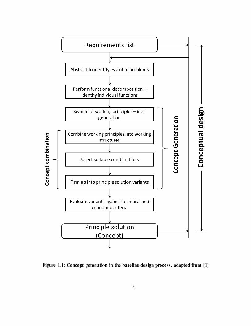
3
Figure 1.1: Concept generation in the baseline design process, adapted from [1]

4
To perform conceptual design, a list of requirements is abstracted to identify the
essential problems [1]. The overall functionality required of the system is obtained and a
functional decomposition is performed to identify smaller individual functions that sub-
systems must perform in order to fulfill the overall functionality of the system. The
concept generation process is based on the list of individual functions that form part of
the functional decomposition of the design task.
1.2 Tools for supporting concept generation
Concept generation consists of two distinct phases: (a) the generation of ideas
(means) to fulfill the specific functional requirements of the system (idea generation in
Figure 1.1) and (b) the combination of means to generate system level concepts (Concept
combination in Figure 1.1), while the boundary between the phases is gray [1]. Several
tools exist that support these idea generation activities [12]. Intuitive idea generation
techniques such as brainstorming, method 6-3-5, or C-sketch can be used to generate the
means to fulfill the functional requirements of a system, or other methods such as
benchmarking, design catalogs or the design repository can be used [13]. Research has
been done on evaluating the use of different functional representations and function
interaction models to support concept generation [14-16]. After generating a number of
potential means to fulfill all the functions of the system (using any functional
representation), combinatorial tools are used to integrate the smaller means together to
form system concepts. The focus of this research is on the combinatorial aspects of the
concept generation process.

5
Different combinatorial tools can be classified into intuitive tools such as
storyboarding and affinity method, and systematic combination tools such as Osborn’s
checklist and action verbs [12, 17]. Additionally, morphological matrices can be used as a
systematic combination or an intuitive tool. The morphological matrix (also referred to as
morphological charts, morphology charts or concept combination tables) is a very
powerful, simple, and systematic combinatorial tool. Morphological matrices use the
principle of morphological thinking which is a systematic full-factorial combination of all
possible combinations of fragments that can together constitute a system.
1.3 Morphological thinking and use of morphological matrices in concept generation
Morphological thinking or morphological analysis is essentially a systematic
combination method used to explore the complete set of possible relationships within any
multi-dimensioned problem that can be decomposed into its constituent sub-problems.
Since its original use in the field of astronomy, morphological analysis has been extended
for use in a number of fields, one of them being engineering design [18]. A detailed
review of the development of the morphological technique is presented in [19].
In engineering design, morphological analysis is used as a tool to support
conceptual design because it facilitates a systematic and visual exploration of the
identified design space [1, 2]. Morphological analysis is used within conceptual design as
the basis for exploration of the design space, where the functions represented in the
functional decomposition are listed against the means to achieve each of those functions

6
in a two dimensional matrix. The focus of this research is on the combinatorial aspects of
morphological matrices. A common representation of the morphological matrix is
illustrated in Table 1.1 with the functions listed along the column and the means listed
along the corresponding rows.
Table 1.1: Representation of a morphological matrix
Functions Means to fulfill each function
(Means)
F1 M1,1 M1,2 M1,3 … M1,m
F2 M2,1 M2,2 M2,3 … M2,m
F3 M3,1 M3,2 M3,3 … M3,m
… … … … … …
Fn Mn,1 Mn,2 Mn,3 … Mn,m
The morphological matrix is used to generate design concepts by combining one
means from each of the rows illustrated in Table 1.1 into a single system concept. The
generated combination (system concept) will thus achieve the listed functional
requirements of the system because all the identified functions of the system will be
fulfilled by at least one means that forms part of the generated system concept.
Additional features or characteristics resulting from the combinations of the means may
add or reduce the functional performance of the system, although the essential
7
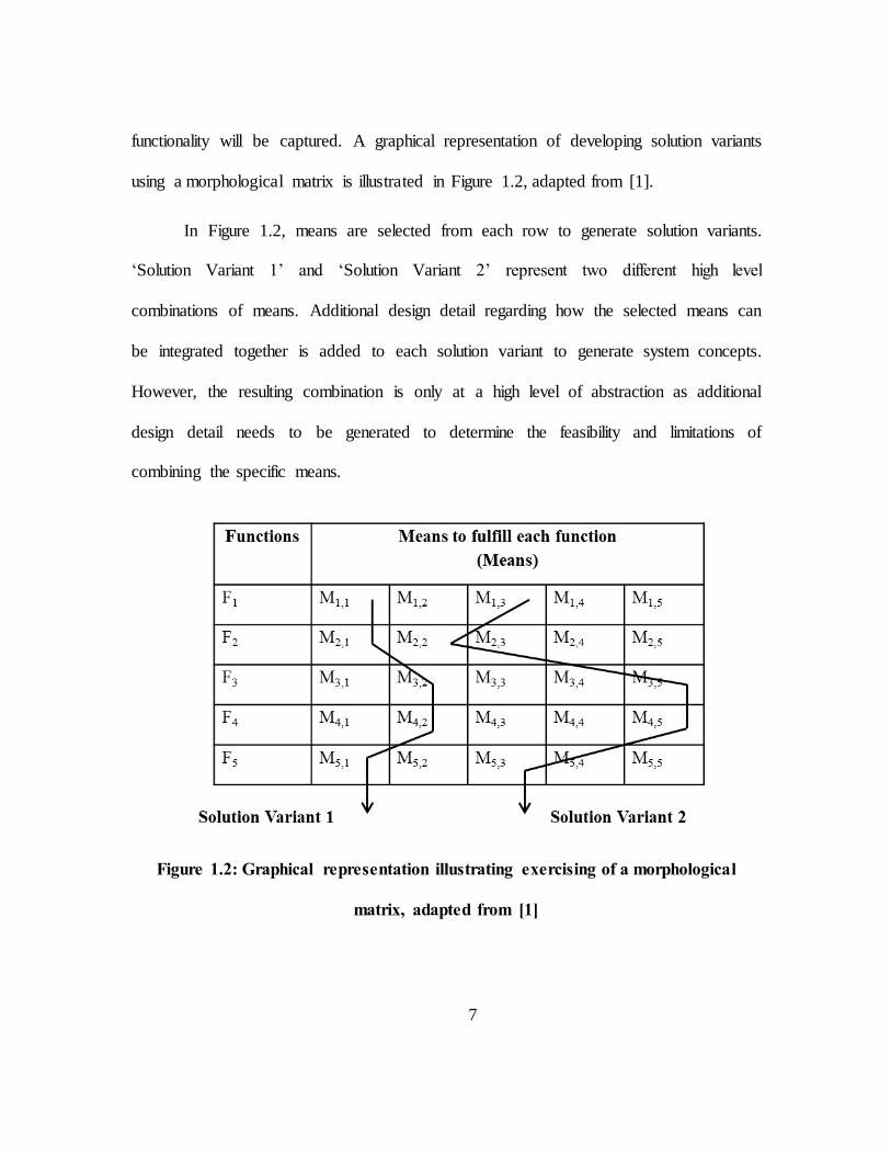
functionality will be captured. A graphical representation of developing solution variants
using a morphological matrix is illustrated in Figure 1.2, adapted from [1].
In Figure 1.2, means are selected from each row to generate solution variants.
‘Solution Variant 1’ and ‘Solution Variant 2’ represent two different high level
combinations of means. Additional design detail regarding how the selected means can
be integrated together is added to each solution variant to generate system concepts.
However, the resulting combination is only at a high level of abstraction as additional
design detail needs to be generated to determine the feasibility and limitations of
combining the specific means.
Figure 1.2: Graphical representation illustrating exercising of a morphological
matrix, adapted from [1]

8
One of the principal characteristics of the conceptual design stage is the lack of
generation of design details for each of the identified means [8, 20]. Consequently, when
using the morphological matrix for combining the means into system concepts, it is
difficult to identify which means are compatible with others to support their physical
combinations. Therefore, simply choosing one means from each row may not yield a
system concept if the means cannot physically be integrated into a working mechanism.
Pahl & Beitz mention four guidelines for the use of morphological matrices to facilitate
the identification of compatible means [1]:
the functions are listed in the order in which they appear in a function
structure representation
the means are arranged with the help of additional column parameters
the means are also graphically represented within the cells with rough
sketches
the most important characteristics and properties of the means are recorded
Although these guidelines are useful, they do not provide detailed guidance on
how to identify compatible means. Hence, the first limitation of the use of morphological
matrices can be stated as the following.

9
The combination of means within a morphological matrix can be done using three
approaches:
1. systematic combination of all means (a full factorial approach)
2. random combinations of means
3. intelligent combinations of means
The systematic combination approach can identify all the possible combinations
and thus allow the designer to choose the best system concept from the entire set, thus
ensuring the selection of the optimum concept (this reflects the essence of the
morphological analysis technique). However, the major limitation of this method is the
number of combinatorial possibilities that must be explored. A design task that is
decomposed into ten functions with five means identified to fulfill each function has 510
(~10 million) combinatorial possibilities. It is not practically possible to explore all these
combinations to identify the optimum system concept.
The approach of random combinations identifies one means from each row
randomly to generate system concepts. This method has an advantage in that the
randomness of the method can result in the combination of unexpected means that force
Limitation 1: It is challenge to identify compatible means from within the
morphological matrix to understand which means can be paired with others to
generate system concepts.

10
the designers to think deep into how the combinations can be achieved, thus leading to
innovative system concepts. However, this approach also has a serious limitation in that
the randomness of the method can result in potentially good system concepts from being
ignored altogether. Some initial studies done within the Clemson Engineering Design
Applications and Research (CEDAR) laboratory have indicated that the quality of means
populated in a morphological matrix tends to be clustered towards the beginning and end
of each row of means. Based on such observations, the randomness of selection of means
for combinations can be biased towards the good quality means to yield improved results.
However, the modification may yet fail to identify potentially good solutions from within
the clustered regions of the morphological matrix containing good quality means.
The intelligent combination approach conceptually lies in between the previous
two approaches. While this method does not explore the design space completely as per
the full factorial approach, it does not rely on uninformed random combinations to
generate system concepts. Instead, this approach uses various strategies to identify the
different combinations of means and the order of combinations of means to explore the
design space. As the means are at a high level of abstraction and there is a lack of design
detail for each of the means, quantitative methods cannot be employed to explore the
design space. Therefore, a qualitative approach must be taken to generate the system
concepts. Various strategies are employed in literature and some of these will be
explained in the next section.

11
1.4 Identification of research gaps
Various strategies have been employed to intelligently combine means through
modification of the traditional morphological matrix in some manner [21-24] or through
combination algorithms exercised in a traditional morphological matrix [25]. These
strategies reduce the number of combinations considered by employing some
computational methods to determine the feasibility and compatibility information of
means with respect to each other [21-24, 26], with the exception of [25] which uses a
qualitative method.
The computational models require the definition of a large amount of information
regarding each of the means in order to facilitate their use. The information to be defined
include descriptions of each means in terms of physical, statistical or combination of
physical and statistical equations [21], approximations of geometrical, performance of
compatibility information using scales [22], or calculation of scores of generated
concepts [23]. The defined information is then used to check for compatibility between
means and address to a limited degree the problem of identifying which means are
compatible with each other. Although the number of combinations explored are less of a
concern due to the use of automated computer-aided techniques [21, 22], the first
challenge of identifying compatible means is still not entirely addressed due to the
practical limitations of providing the required information for each of the means
identified. The cost of computation might also be a challenge considering the lack of
definitive information, need to specify a large number of design variables, number of
12
potential means, and the uncertainty or variance of the results of computation. This
problem multiplies when such a tool is used within a large design firm that has a wide
variety of products.
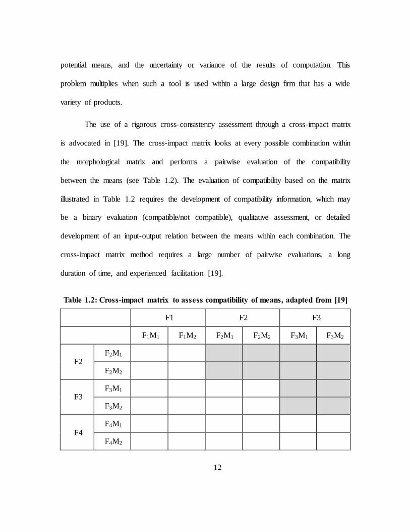
The use of a rigorous cross-consistency assessment through a cross-impact matrix
is advocated in [19]. The cross-impact matrix looks at every possible combination within
the morphological matrix and performs a pairwise evaluation of the compatibility
between the means (see Table 1.2). The evaluation of compatibility based on the matrix
illustrated in Table 1.2 requires the development of compatibility information, which may
be a binary evaluation (compatible/not compatible), qualitative assessment, or detailed
development of an input-output relation between the means within each combination. The
cross-impact matrix method requires a large number of pairwise evaluations, a long
duration of time, and experienced facilitation [19].
Table 1.2: Cross-impact matrix to assess compatibility of means, adapted from [19]
F1 F2 F3
F1M1 F1M2 F2M1 F2M2 F3M1 F3M2
F2 F2M1
F2M2
F3 F3M1
F3M2
F4 F4M1
F4M2

13
However, it is difficult to prescribe a method to identify compatible means within
the morphological matrix when there is a large number of means for each function, there
are many functions, and when the means are represented at a high level of abstraction to
encourage designers to think of variations to the basic idea for adaptation into concepts.
The qualitative method prescribed in [25] suggests the use of the designers’ knowledge
and intuition to identify compatibility among means, which may be a more practical
method of assessment as it eliminates the need to understand the compatibility
information of means that you do not consider.
Therefore, although compatibility between means may be addressed to some
degree, it is still a major challenge to identify an effective way of navigating the design
space represented by the morphological matrix, especially when the morphological
matrix contains a large number of functions and means. Hence, the second limitation of
the morphological matrix approach can be stated as the following.
Additionally, existing literature does not provide guidance to designers regarding
how the combination of means within the morphological matrices can be done in order to
Limitation 2: There are no sufficient guidelines available to designers on how to
effectively navigate the design space represented by a morphological matrix using a
qualitative approach without performing a full-factorial combination of the means
populated in the morphological matrix.

14
produce good quality concepts. Designers are faced with many potential options for them
to explore, although no real guidance is provided on where to begin, what directions to
proceed, how deep to explore, provide tools that encourage designers to ‘think outside the
box’, identify implicit assumptions, challenge existing paradigms, or bring about
innovation in their design concepts. The morphological matrix populated with a number
of functions and means presents a large number of potential combinatorial possibilities,
and a wealth of information. It can be a daunting task to perform a detailed exploration of
all the potential options that the morphological matrix presents and be confident in the
concepts that have been generated with respect to being able to judge the feasibility of the
concept with respect to requirements and generate a rank ordered list of potential
concepts. This statement has been supported by some interviews conducted with users of
the morphological matrix. Therefore, a third limitation of the morphological matrix can
be stated as follows.
In light of the limitations that have been identified, two main research gaps have
been identified. These are stated as follows:
Limitation 3: The morphological matrix facilitates a high level combination of means
into system concepts. There are no sufficient guidelines on how to generate details,
identify implicit assumptions, challenge paradigms, foster innovation and improve
confidence in the concepts generated.

15
1. There exists an opportunity to identify different ways to effectively navigate the
design space sufficiently within a time constraint without requiring a full factorial
combination of all the means populated within a morphological matrix.
2. There exists an opportunity to provide guidance to designers on how to generate
good quality concepts with sufficient design detail, while facilitating the
generation of innovative concepts, identification of implicit assumptions,
challenge existing paradigms, and helping to build confidence in the concepts that
have been generated.
The goal of this research is to address the identified research gaps. The outline of
the thesis is provided in the next section.
1.5 Thesis outline
In this thesis, the two research gaps identified in the previous section are
addressed through the development of an Integrated Idea Generation (IIG) method. Some
initial testing and refinement of the method is performed and the results are discussed.
The layout of the thesis is as follows:
Chapter 2: Discussion of the specific research objective, the research questions
formulated and the tasks that must be completed to address those research
questions.
Chapter 3: Description of the IIG method with detailed step by step guidance.

16
Chapter 4: Application of the IIG method in industry for the design of a seat
chassis mechanism, with a detailed discussion of the steps followed.
Chapter 5: Discussion of user studies (2) and interviews (6) conducted to obtain
qualitative feedback about the IIG method, discussion of the results, conclusions
from the testing, and description of the advantages and challenges of the IIG
method based on findings.
Chapter 6: Summary of the IIG method and results of testing with an overview of
the main advantages and challenges of the IIG method, and discussion of future
work.

17
CHAPTER TWO
RESEARCH OBJECTIVE AND SCOPE
This chapter outlines the main research objectives, describes the specific research
questions that are being addressed, the tasks that need to be completed to address the
research questions and the value of conducting this research.
2.1 Research objective
The overarching objective of this research is to provide guidelines to a designer
on how to effectively navigate the design space within a morphological matrix without
performing a full factorial combination of all the means and to generate innovative and
good quality concepts.
2.2 Research questions
2.2.1 Research Question 1:
Can we develop a method to allow a designer to effectively navigate the design
space sufficiently without performing a full factorial combination of all the means within
a morphological matrix?

18
2.2.2 Research Question 2:
What guidelines can be provided to designers to generate system concepts that
have sufficient design detail to make a confident judgment on the feasibility of the
concept with respect to the requirements and generate a rank ordered list of potential
system concepts?
2.3 Research Tasks
To address the research objective, the following tasks must be completed:
1. Develop a method of exploring the design space more effectively to generate
good quality innovative concepts.
2. Test and refine the method to improve efficiency, effectiveness, usability and ease
of learning.
3. Validate the method with different users – novice and experienced designers.
4. Develop tools to support concept generation using the method.
5. Explore potential for use in different domains to make the method domain
independent.
6. Teach the method to designers; perform continuous assessment and refinement of
the method.

19
2.4 Scope of this research
The scope of this specific research is limited to the development of a method, and
an initial testing and refinement to understand the method in more depth. The research
questions can be addressed to a significant degree by the completion of the first two
tasks. However, the first task – to develop a suitable method, is the most challenging and
forms the basis for the remaining tasks. Hence, the most significant efforts have been on
the development of an appropriate method to support concept generation. The method
must address the following requirements:
1. Provide a method for sufficient exploration of the design space without requiring
a full factorial combination of all the means populated within a morphological
matrix.
2. Provide detailed guidance to novice and experienced designers on how to
generate concepts with sufficient design detail to confidently judge the feasibility
of the concept with respect to requirements and generate a rank ordered list of
concepts.
3. Encourage designers to perform combinations of means from different
perspectives, using different strategies, and foster innovative concepts.
4. Encourage experienced designers to identify their implicit assumptions, challenge
the existing paradigms, and allow the generation of design detail within specific
areas of interest within a system concept that is of special interest.

20
5. Guide novice designers in effectively navigating the design space, while
facilitating a deeper understanding of the design task and the effects of specific
physical combinations on the system.
6. Facilitate a thorough understanding of the design space and allow the
identification of the potential and limitations afforded by the design space
explicitly.
7. Provide traceable design documents that capture the ideas explored, justification
for design decisions, facilitate analysis of design project, assessment of
success/failure and support redesign.
The remaining chapters of the thesis will explain the method that was developed,
illustrate the application of the proposed method in industry, describe the testing that was
performed to develop a deeper understanding of the method, and highlight the potential
for the method as well as some of the challenges of using the method.

21
CHAPTER THREE
INTEGRATED IDEA GENERATION (IIG) METHOD
3.1 Overview of the method
A systematic concept generation method, the Integrated Idea Generation (IIG)
method, is proposed that aims to address the research questions identified in Chapter 1.
Specifically, the IIG method aims to achieve the following objectives:
1. Provide guidelines to a designer to systematically generate system level
conceptual ideas from the individual means represented in a morphological matrix
2. Generate design detail for generated concepts in order to exercise sound
engineering judgment regarding their feasibility for the design task and facilitate a
high level comparison against alternate concepts
3. Reduce the number of combinations required to be performed by the designer in
order to sufficiently explore the design space to generate system level concepts.
The IIG method is a systematic method of combining the means identified in a
morphological matrix to form system level conceptual ideas. Therefore, in order to apply
the IIG method, the designer must first perform the following three steps:
1. Perform a functional decomposition of the design task,
2. Generate ideas to fulfill the identified functions, and

22
3. List the identified functions against all the means generated to fulfill each
function in a morphological matrix.
The basis of the IIG method is the generation of sub-system concepts through
focused ideation on specific functional combinations within the identified functional
decomposition of the design task. The IIG method is presented as a six step process
consisting of the following steps, as illustrated in Figure 3.1.
The steps of the IIG method illustrated in Figure 3.1 are:
1. Grouping of the individual means in the morphological matrix
2. Preliminary filtering of the morphological matrix and identification of innovative
means
3. Identification of functional combinations to perform focused ideation
4. Generation of sub-system concepts
5. Integration of sub-system concepts systematically to form system level concepts
6. Iterate to identify alternative concepts
In Step 1, the means populated within the morphological matrix are initially
categorized into solution streams (indicated as “S. Streams” in Figure 3.1) which are
groups of similar means. For example, a disc brake and a drum brake can be grouped
together under ‘friction based braking mechanisms’. In Step 2, an initial filtering is
performed on the means within the morphological matrix to identify means that are either
clearly infeasible or seem innovative or promising.

23
Figure 3.1: Overview of the Integrated Idea Generation method
24
In Step 3, pairwise functional combinations are extracted out of the functions
from the morphological matrix along with the means generated to fulfill those functions,
to explore how their specific combinations manifest themselves in the physical domain.
In Step 4, ideas are generated for these functional combinations (or functional modules)
to create sub-system solutions that achieve some functionality. In Step 5, these sub-
system solutions are then again represented in an additional morphological matrix that
lists the specific functional modules against the generated sub-system solutions. Pairwise
combinations are then generated for the functional modules from the resulting
morphological chart and focused ideation is again performed to generate a higher level
sub-system solution with additional functionality. This process is continued until all the
functional requirements identified in the functional decomposition are achieved in the
physical domain through the systematic pairwise combinations of functional modules. In
Step 6, alternative functional combinations and means are explored and the process is
repeated from Step 1 to generate alternative design concepts. However, the generation of
alternative concepts need not always start from Step 1; Steps 2, 3 could also be used as
starting points for the design of alternatives. This process of combining means within the
morphological matrix results in the generation of system-level conceptual ideas with a
greater understanding of the specific sub-systems that comprise the system concept.
Design literature supports the use of tools to support combination of means from
the morphological matrices. Pahl and Beitz [1] propose the use of a compatibility matrix
to determine the feasibility of potential combinations of means. Similarly, the IIG method

25
uses options matrices to provide a focused and detailed exploration of the design space.
Compatibility is one of the challenges that is addressed by the options matrices, although
the major aim of using the options matrices is the visualization of the sub-system space
(explored and yet to be explored) and the encouragement to develop design details in the
combinations of the means. Options matrices are proposed for several reasons including:
1. Identification and integration of functions not identified in the initial
morphological matrix
Functions that must be performed by the system are not always included in
the morphological matrix to limit the number of functions being provided
to a designer. This is because increasing the size of a morphological
matrix can adversely affect the quality of the concepts generated [27].
Therefore, only the major functions are listed in the morphological matrix.
For example, although “Provide locking” may be a function that must be
performed by a system, the functional decomposition may not specifically
list “Actuate locking mechanism” as a function.
2. Identification and integration of sub-functions that are only identified when
combining specific means and thus are not relevant to all the means in the
morphological matrix
Additional functions may be identified as a result of the specific
combination of two or more means. As these are dependent on specific
means, they are not listed in the morphological matrix.

26
3. Generation of several different geometric and physical combinations for the
means within the morphological matrix
There may be several different ways in which two means can be combined
to obtain desirable characteristics from the resulting sub-system. The
options matrix facilitates the development of design details for the
different combinatorial possibilities.
4. The exploration of the combination of means in the morphological matrix at a
high level of detail
The options matrix allows the designers to explore the combinations of
specific means from the morphological matrix at a deeper level to
understand the specific advantages that can result from the different
combinations.
A detailed discussion of each step of the IIG method is presented in the next
section.
3.2 Steps of the IIG method
3.2.1 Step 1: Grouping of the individual means in the morphological matrix
The individual means from the morphological matrix are organized and grouped
into solution streams according to their similarities. Each solution stream is a group of
similar individual means. It may be possible to group the means in more than one way
based on similar working principles, similarity of components, or other explicit design

27
specific criteria such as perceived strength, reliability or complexity. Affinity
diagramming, card sorting and the gallery method are techniques that can be used to
perform the grouping of the means [1, 2, 12].
The classification of the means is also discussed in the Concept Classification
Tree method in [2] and in the use of working principles as means discussed in [1]. The
grouping of the means within the morphological matrix provides many benefits similar to
the concept classification tree method. Some of the benefits include the following:
1. Help designers to identify additional working principles and mechanisms that
were not previously apparent,
2. Stimulate the identification of potential high level strategies to generate system
level concepts, and
3. Identify compatible working principles or means across functions, thus generating
different ways of combining the means to form small sub-systems having some of
the functionality required from the system.
The solution streams within the morphological matrix can be represented as
illustrated in Table 3.1. In Table 3.1, the solution streams are represented in separate
rows, altering the standard structure of the morphological matrix. This representation of
the solution streams allows the designer to quickly identify all the solution streams more
efficiently and provides a compact representation of the morphological chart to facilitate
ease of documentation.

28
The result of Step 1 is the generation of a morphological matrix with means
grouped according to their similarities that allow the designers to easily identify the high
level working principles that are being considered as potential solutions and stimulate the
generation of potential strategies for combining the ideas into system level concepts.
Table 3.1: Organization of solution streams in a morphological matrix
FUNCTIONS SOLUTION
STREAMS MEANS
F1 Solution Stream 1.1 M1.1 M1.2 M1.3
Solution Stream 1.2 M1.4 M1.5 M1.6
F2 Solution Stream 2.1 M2.1 M2.2
Solution Stream 2.2 M2.3 M2.4 M2.5 M2.6
F3
Solution Stream 3.1 M3.1 M3.2
Solution Stream 3.2 M3.3 M3.4 M3.5
Solution Stream 3.3 M3.6
3.2.2 Step 2: Preliminary filtering of the morphological matrix and identification of
innovative means
After grouping the means in the morphological matrix, a preliminary filtering is
performed on the means identified in the morphological matrix. This initiates a
discussion of the merits and demerits of each of the means. Every means that is
represented in the morphological matrix is discussed with respect to the potential
29
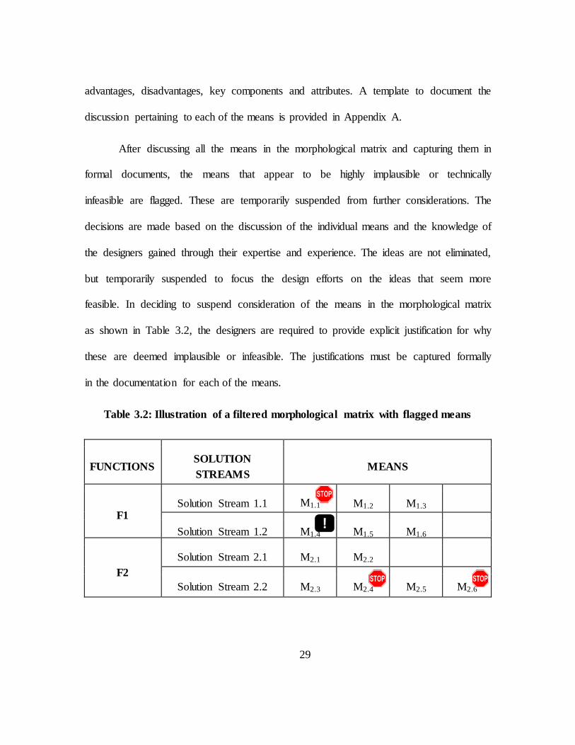
advantages, disadvantages, key components and attributes. A template to document the
discussion pertaining to each of the means is provided in Appendix A.
After discussing all the means in the morphological matrix and capturing them in
formal documents, the means that appear to be highly implausible or technically
infeasible are flagged. These are temporarily suspended from further considerations. The
decisions are made based on the discussion of the individual means and the knowledge of
the designers gained through their expertise and experience. The ideas are not eliminated,
but temporarily suspended to focus the design efforts on the ideas that seem more
feasible. In deciding to suspend consideration of the means in the morphological matrix
as shown in Table 3.2, the designers are required to provide explicit justification for why
these are deemed implausible or infeasible. The justifications must be captured formally
in the documentation for each of the means.
Table 3.2: Illustration of a filtered morphological matrix with flagged means
FUNCTIONS SOLUTION
STREAMS MEANS
F1 Solution Stream 1.1 M1.1 M1.2 M1.3
Solution Stream 1.2 M1.4 M1.5 M1.6
F2
Solution Stream 2.1 M2.1 M2.2
Solution Stream 2.2 M2.3 M2.4 M2.5 M2.6

30
The most innovative and promising means are also identified from the
morphological matrix. This is consistent with the pruning of the concept classification
tree as discussed in [2] and the concentration of design efforts on promising solutions as
discussed in [1]. Table 3.2 illustrates a filtered morphological matrix with means that are
suspended from further consideration temporarily (indicated by the ‘STOP’ signs) and
innovative means to focus attention on (indicated by the exclamation mark).However,
there is a potential that two “bad” means can result in a feasible sub-system combination
that has desirable characteristics. Hence, it is not recommended to avoid consideration of
any means altogether; it is advisable to concentrate the design efforts initially on those
means that seem feasible and innovative to generate concepts and to explore other
seemingly less feasible options later to create alternative concepts.
The result of Step 2 is the generation of a filtered morphological chart with the
most promising and innovative means to generate potential combinations and the
temporary elimination of the implausible means.
3.2.3 Step 3: Identification of functional combinations to perform focused ideation
The basis of the proposed method is the idea of generating system concepts using
pairwise functional combinations. Functional subsets are extracted along with the means
pertaining to those functions to perform focused ideation on exploring the different ways
of combining the specific functions. Each subset consists of a pair of coupled, compatible
or anti-functions that can be combined to form desirable or innovative sub-systems. The

31
functions may be related to each other temporally, geometrically, or logically. For
example, ‘transport container with liquid’ is a function that occurs after ‘fill container
with fluid’. Similarly, ‘move mechanism forward’ is a function that is logically related to
‘lock mechanism’. The selection of functional combinations may also depend on an
identified strategy to combine the functions to form a system concept. For example, if
sub-systems of a large system are outsourced from an external supplier, the choice of
functional combinations may be such that the functionality of an outsourced sub-system
is achieved independently of the rest of the system.
The selection of functional combinations may be subjective based on individual
designers, design task and design focus. Different functional combinations may be
possible and desirable to create a wide range and variety of potential concepts. However,
it is important that an initial set of functional combinations is chosen to begin focused
ideation on the possible ways of implementing the functional coupling in the physical
domain.
The objective is to identify independent functional combinations from within the
functions represented in the morphological matrix. Although one function could
potentially be coupled with more than one other function to generate a potentially
interesting sub-system, only one pairing is chosen for each function initially. Other
possible combinations can be explored in later stages during the generation of alternative
design concepts. During the first pass at generating the system concepts, each function is

32
not represented in two different functional combinations. Table 3.3 illustrates the
acceptable functional combinations in a morphological matrix that has 5 functions.
In Table 3.3, the functional combinations are represented by the functions
enclosed in square brackets. The first row of potential functional combinations is an
acceptable set of functional combinations. Although there is one function that does not
form part of any group, this is acceptable as it is not always immediately apparent how
some functions can be part of a functional combination.
Table 3.3: Acceptability of functional combinations to perform focused ideation
Potential functional
combinations extracted out of
the morphological matrix
Acceptability of
functional
combinations
Reason for non-
acceptability
[F1 & F2], [F3 & F5], F4 Yes None
[F1, F2, F3], [F4 & F5] Yes None
[F1, F2, F3, F5], F4 No Too many functions in
one combination
[F1 & F2], [F3 & F5], [F4 & F5] No
Duplicate function in two
independent functional
combinations
The functional combinations in the second row are also acceptable despite one
functional combination having three functions. This is because sometimes functions are
very intricately coupled or the geometric compatibility of the respective means is readily
apparent that their combinations can be easily explored in detail. However, it is not

33
recommended to have more than 3 functions as part of a functional combination as it
becomes more difficult for the designers to effectively visualize and explore their
combinations in much detail. Therefore, the third row of Table 3.3 is not an acceptable
set of functional combinations. The fourth row is not acceptable because function 5 is
represented in more than one functional combination. The representation is not
acceptable because each of the functional combinations represented in rows 1 and 2
results in the generation of sub-system ideas that can then be integrated successively to
form a system level concept. When one function is represented more than once, as in row
4, the subsequent integration of the generated sub-system ideas becomes complicated
because there will be more than one means to achieve one function which brings
redundancy into the system concept. When one function can be potentially combined
with more than one function, all except one of those combinations are reserved for
generation of alternative system concepts. It is important to note that these are not being
neglected or ignored, but reserved for consideration later in the concept generation
process.
The result of Step 3 is the generation of functional combinations to perform
focused detailed exploration of the possible ways of realizing the functional coupling in
the physical domain.

34
3.2.4 Step 4: Generation of sub-system concepts
The objective of this step is to examine in detail, the possible advantages and
disadvantages that may result from the specific combinations of the means pertaining to
the functional subset. Focused idea generation is performed on each subset based on
innovation challenges to generate sketches of the various layouts of the combinations of
means to achieve the functional integration.
3.2.4.1 Innovation Challenges
Combinations of the means can be performed using different perspectives
depending on the applications of the system. For example, the physical coupling of the
means may be designed to minimize the number of possible connecting members,
minimize number of joints, reduce overall size, provide certain structural strength,
increase robustness, or other specific targets. These different perspectives are called
innovation challenges. The combinatorial perspectives encourage the designers to think
of the different principles using which to explore the combinations of the means. The
perspectives are called innovation challenges because focusing on developing ideas using
natural means without any external forced stimuli might lead to a focused vision and the
design of systems that may be derivatives of previous generations rather than being
innovative. However, the innovation challenges are not restricted to combinatorial
perspectives. They are the challenges resulting from questioning the four main domains
of design knowledge leading up to concept generation – design task statement, list of

35
requirements, function model and the design space. The innovation challenges are
broadly classified into the following categories:
1. Requirements challenging innovations: These may be questions asked of the
requirements to identify implicit assumptions made by designers based on the list
of requirements.
a. The scope of the requirements may be challenged. For example, the
requirements for a mechanical system may specify a maximum deflection
distance under load. However, which components of the system must be
structural may not be stated. Therefore, the challenge of whether or not
certain components of a mechanical system can be structural/non-
structural results in the challenging of the requirements.
b. It is also possible that sometimes requirements are misleading. For
example, sometimes requirements may state that no electrical wires can be
used in the system. However, the required intention may be that no wires
are visible.
2. Functional redefinition innovations: These are challenges that result in the
redefinition of existing functional requirements or the identification of
additional/intermediary functional requirements pertaining to specific
functional/geometric combinations.
a. Redefinition of functional requirements – Design tasks may be
functionally decomposed in a variety of ways and hence, it cannot be

36
argued that any one way of functional decomposition is the only right way
of abstracting the functional requirements of a system. The reformulation
of a particular function or the function model can be classified as a
functional redefinition innovation.
For example, if a movement mechanism must provide a motion in
2 dimensions, changing the decision to use a combination of 2 one
dimensional mechanisms to use a single two dimensional mechanism (or
vice versa) constitutes a functional redefinition.
b. Identification of additional/intermediary functions – Sometimes, all the
functions required of mechanical systems/sub-systems are not mentioned
in the morphological chart or defined in the functional decomposition.
For example, “Provide locking” may be defined in the functional
decomposition although “Actuate locking mechanism” may not explicitly
be stated. This ensures the focus of the designers’ attention on the major
functions, and reduces the size of the morphological matrix. Increasing the
size of a morphological matrix does not always translate to increased
quantity/quality of concepts generated [27].
Also, sometimes intermediary functions are required to form the
interface between two mechanisms which may be specific to the particular
mechanisms and hence cannot be mentioned generically in the functional
decomposition of a system.

37
3. Design space exploration innovations: These are challenges that serve as stimuli
for designers to identify additional means to fulfill particular functions or
functional combinations. For example, challenging designers to think about
different physical principles to achieve a function, use of biomimetic ideas, or
TRIZ principles could serve as external stimuli to generate additional ideas.
4. Combinatorial innovations: These are different perspectives that force designers
to consider different ways of achieving functional combinations in the physical
domain. These may be perspectives that are used as a common theme throughout
the various functional combinations leading up to the system level concepts or
they may be limited to specific functional combinations within the system.
For example, the idea of exploring what happens if the components
within a specific sub-system assembly are mechanically inverted is a localized
challenge compared to the idea of generating sub-systems using the perspective
of ‘robustness’, which is a more global challenge within the system design.
The innovation challenges are used as themes to explore the different functional
combinations leading up to the generation of sub-systems. They drive the designers to
explore different combinations from the functional space using different perspectives and
geometric combinations that are not apparent from the morphological matrix. The
different themes are explored within functional subsets using options matrices.

38
3.2.4.2 Options Matrices
An options matrix is a two dimensional matrix where the means for one function
are listed against the means for a second function in order to explore the combinations of
the means pertaining to the functions (see Table 3.4).
Table 3.4: Illustration of an options matrix
Means for function 2
F2M1 F2M2 F2M3
Mea
ns
for
funct
ion 1
F1M1 A1, A2 HAS TOO MANY ISSUES
OF COMPATIBILITY
F1M2 POTENTIALLY INNOVATIVE
COMBINATIONS, EXPLORE IN DETAIL.
F1M3 CURRENTLY EXISTING MECHANISMS,
TO BE EXPLORED LATER
It provides a focused morphological approach to the combination of two
functions, and helps to visualize the design space. The options matrices form a platform
to generate design details for the generated combinations, building upon the compatibility
matrix presented in [1], and using a high level and less rigorous approach compared to
the cross-impact matrix discussed in [19].
39
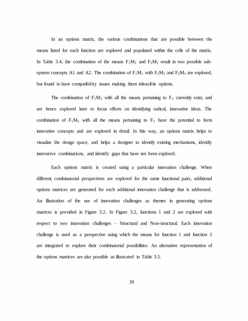
In an options matrix, the various combinations that are possible between the
means listed for each function are explored and populated within the cells of the matrix.
In Table 3.4, the combination of the means F1M1 and F2M1 result in two possible sub-
system concepts A1 and A2. The combination of F1M1 with F2M2 and F2M3 are explored,
but found to have compatibility issues making them infeasible options.
The combination of F1M3 with all the means pertaining to F2 currently exist, and
are hence explored later to focus efforts on identifying radical, innovative ideas. The
combination of F1M2 with all the means pertaining to F2 have the potential to form
innovative concepts and are explored in detail. In this way, an options matrix helps to
visualize the design space, and helps a designer to identify existing mechanisms, identify
innovative combinations, and identify gaps that have not been explored.
Each options matrix is created using a particular innovation challenge. When
different combinatorial perspectives are explored for the same functional pairs, additional
options matrices are generated for each additional innovation challenge that is addressed.
An illustration of the use of innovation challenges as themes in generating options
matrices is provided in Figure 3.2. In Figure 3.2, functions 1 and 2 are explored with
respect to two innovation challenges – Structural and Non-structural. Each innovation
challenge is used as a perspective using which the means for function 1 and function 2
are integrated to explore their combinatorial possibilities. An alternative representation of
the options matrices are also possible as illustrated in Table 3.5.

40
Table 3.5: Illustration of an alternative representation of an options matrix
Innovation challenge 1 Innovation challenge 2 Innovation challenge 3
F1M
1
F2M1
F2M2
B1
B2
F2M3
C1
C2
F1M
2
F2M1
F2M2
F2M3
Figure 3.2: Illustration of themes of innovation generate options matrices

41
In the alternative representation, a single consolidated options matrix is used to
represent the various innovation challenges used within the same functional subsets. Each
innovation challenge is listed in subsequent columns, which allows for a more compact
representation, although the resulting matrix is comparatively more complex. However,
both representations serve the same purpose – to generate additional combinatorial
possibilities for functional subsets.
In Table 3.5, every means from one function is listed against all the means from
the second function to represent the 2 dimensional nature of the combinations in a 1
dimensional format. The cells B1, B2 and C1, C2 illustrate the idea that there may be
more than one potential configuration to combine the means F1M1 with F2M2 and F1M1
with F2M3 respectively.
3.2.4.3 Generating sub-system concepts
The functional combinations that are identified in Step 3 are carried forward to
options matrices to explore their potential combinatorial possibilities. The means chosen
for the functions are the promising and innovative means that were identified as a result
of Step 2. Using the different innovation challenges and different functional
combinations, various possible configurations for sub-systems are generated. All the
functional combinations identified in Step 3 are used to generate sub-systems.

42
The result of Step 4 is the generation of some sub-systems that represent
innovative or promising ideas to realize a limited functionality required of the system as a
whole.
3.2.5 Step 5: Integration of sub-system concepts systematically to form system level
concepts
Generation of sub-system concepts using options matrices as described in Step 4
is a focused and detailed exploration of a specific part of the system. The ideas developed
for the specific parts are combined systematically to generate system concepts using an
interplay of the options matrices with different levels of morphological charts. An
illustration of the method is provided in Figure 3.3.
In Figure 3.3, the level 1 morphological chart represents the grouped and filtered
morphological chart with all the functional requirements of the system listed against all
the means generated to fulfill those functional requirements. Functional pairs are then
extracted from this morphological chart to generate sub-system concepts as explained in
Step 4 using the options matrices. This is graphically represented by the options matrices
following the level 1 morphological chart.
The sub-system concepts that are generated using these options matrices are then
populated in a higher level morphological chart represented in Figure 3.3 by the level 2
morphological chart.

43
The level 2 morphological chart utilizes the structure illustrated in Table 3.6. In a
level 2 morphological chart, the functional pairs that were exported to the options
matrices in Step 4 are listed along the rows against the sub-system concepts (SSC in
Table 3.6) that were generated within the options matrices.
If certain functions were not part of functional pairs exported to options matrices,
these functions and their corresponding means are replicated in the level 2 morphological
chart from the original level 1 morphological chart, as illustrated by F7 in Table 3.6.
Where functional pairs exist, these are listed along each row.
After the level 2 morphological chart is populated, the procedures described in
Steps 1 to 3 are repeated with the new morphological chart, i.e., the sub-system concepts
are grouped according to their similarities, a preliminary filtering is performed on the
sub-system concepts represented in the morphological chart, innovative or promising
sub-system concepts are identified, and new pairings of functions or functional modules
are identified from the morphological chart (see Figure 3.4).
Figure 3.3: Integration of options matrices with level 2 morphological chart

44
Table 3.6: Illustration of a level 2 morphological chart with functional modules
Functional
modules Sub-system Concepts for combinations of function modules
[F1 & F4] SSC14,1 SSC14,2 SSC14,3 SSC14,4 SSC14,5
[F2 & F3] SSC23,1 SSC23,2 SSC23,3 SSC23,4 SSC23,5
[F5 & F6] SSC56,1 SSC56,2 SSC56,3 SSC56,4 SSC56,5
F7 M7,1 M7,2 M7,3 M7,4 M7,5
In Figure 3.4, a design problem that is decomposed into four functional
requirements is used to illustrate the Integrated Idea Generation method. Functional pairs
[F1, F4] and [F2, F3] are extracted out of the Level 1 morphological matrix into
corresponding options matrices. The resulting sub-system concepts generated within the
two options matrices are then reintegrated into a Level 2 morphological chart that lists the
functional pairs against the generated sub-system concepts.
The two functional modules are then listed against each other in a different
options matrix to generate concepts. The resulting concepts fulfill all the functional
requirements of the system and are hence classified as system concepts.
At the end of this step, a set of potential system concepts are generated that
achieve the total functionality required of the system.

45
Figure 3.4: Illustration of the generation of system concepts using higher level
morphological matrices and options matrices

46
3.2.6 Step 6: Iterate to identify alternatives
The objective of this step is to generate alternative conceptual ideas in addition to
the system concepts generated at the end of Step 5. The number and quality of the system
concepts generated at the end of Step 5 are dependent on the following parameters:
specific functional combinations chosen at various levels
specific means or sub-system concepts chosen to pursue design detail at various
levels
specific order of combinations of functions and functional combinations
specific order of combinations of means and sub-system concepts
Therefore, the system concepts generated do not represent a thorough exploration
of the design space. In order to include ideas from across the design space in the system
concepts, iterations are performed using the Steps 1-5 an adequate number of times until
a sufficient quantity, quality, novelty and variety of ideas are represented in the system
concepts that are generated for the given design task. By repeating the steps and varying
the parameters aforementioned, a number of different concepts can be created.
The result of this step is the generation of a number of alternative system concepts
that potentially satisfy all the functional requirements of the system.

47
3.3 Summary of the IIG method
A systematic method of concept generation is proposed to guide a designer to
generate system level conceptual ideas from individual means populated in a
morphological chart. The method requires as a prerequisite, the functional decomposition
of the system and subsequent idea generation to identify means to fulfill the functional
requirements. The method utilizes functional pairing and focused idea generation based
on the functional pairs to generate detailed design options. Focused ideation is performed
on functional pairs through the use of options matrices which are then integrated into a
higher level morphological matrix. Functional modules are extracted out of the higher
level morphological matrices into options matrices and reintegrated into the next higher
level of morphological matrices until system level concepts are obtained. Alternative
system concepts are generated by repeating the steps using different parameters until a
sufficient number of potential feasible concepts have been identified.
The method allows a detailed exploration of the design space without performing
a full factorial combination of all the means identified to fulfill all the functional
requirements. It facilitates the generation of additional ideas as it encourages designers to
generate many ideas to combine the same set of means. By pruning and filtering the ideas
generated during the concept generation process, and using focused ideation methods
through options matrices, the method facilitates an intelligent effective exploration of the
design space whilst generating solutions that have a large amount of design detail. The
specific advantages and challenges associated with this method of concept generation are

48
discussed in Chapter 6. The method is demonstrated using the example of the design of a
seat mechanism in Chapter 4.

49
CHAPTER FOUR
APPLICATION OF INTEGRATED IDEA GENERATION METHOD IN INDUSTRY
The Integrated Idea Generation method explained in the previous chapter is
demonstrated with the example of a seat mechanism for an automotive application. First,
the design problem is defined and the steps leading up to the generation of an initial
morphological matrix are briefly outlined. Second, the steps to generate system level
conceptual ideas using the Integrated Idea Generation method are explained in detail
using examples from the seat mechanism.
The seat mechanism example was developed in collaboration with Johnson
Controls Inc. (herein referred to as JCI) and hence, not all the information that was
generated during the exercise can be entirely revealed to maintain confidentiality.
4.1 Seat mechanism design problem
As was discussed in the previous chapter, the IIG method requires as a
prerequisite, the functional decomposition of the design task and ideas generated to fulfill
the functional requirements listed in a morphological matrix. An overview of the steps
performed to generate the morphological matrix is outlined in this section.

50
4.1.1 Background
A seat mechanism for the driver and front passenger of an automobile is required
that is cheaper than the existing designs, and allows both manual adjustment and power
assisted adjustment. Based on the case study executed by Crouch, a specific range of
motion, described by a hip point (H Point) travel window, was identified as the optimum
range of adjustment that was required to be achieved by a new seat mechanism [28]. The
H point is the basis using which the range of motion of the seat mechanism is generated,
and describes a point on the hip of an occupant seated on the seat pan.
4.1.2 Design task statement
The seat mechanism is required to provide a range of adjustment within the newly
specified H-Point travel window that is less expensive and weighs lesser than the existing
designs. Therefore, the following design task statement is devised.
The newly specified H-point travel window is illustrated in Figure 4.1. The solid
lines enclosing the shaded region in Figure 4.1 illustrate the newly specified H-point
travel window within which the new seat mechanism must provide adjustment for an
“Design a seat mechanism that has both reduced mass and cost over a previous iteration
and that is capable of providing adjustment for a newly specified H-point travel
window.”

51
occupant. The dashed lines represent the original travel window requirement that was
modified. All dimensions shown are in millimeters.
Figure 4.1: Illustration of the newly specified H-point travel window
The total length of horizontal motion required of the mechanism is 10.6 in.
The total length of vertical motion required of the mechanism is 4 in.
Once the design task statement is defined, a list of requirements is obtained that
the new design was required to meet.
4.1.3 List of Requirements
A large number of requirements were provided by JCI for the new seat
mechanism. A detailed list of these requirements and supporting documents are provided
in Appendix B. The requirements addressed in this research are provided in Figure 4.2.
The structural support requirements illustrated are simplified for illustration.

52
1) Adjust the seat position in three degrees of freedom within the new window
a) Provide adjustment in X
i) Limit travel in X (10.6 inches)
ii) Modulate speed/force/torque to X
b) Provide adjustment in Z
i) Limit travel in Z (4 inches)
ii) Modulate speed/force/torque to Z
c) Provide adjustment in Tilt
i) Limit travel in Tilt (± 3°)
ii) Modulate speed/force/torque to Tilt
2) Maintain the set position of the seat when not activated
a) Lock in X, Z Position
b) Lock in Tilt Position
3) Provide structural support for defined load conditions (crash loads)*
a) Allow no displacement in Y
b) Allow no displacement in Yaw, Roll
4) Provide stability (normal and crash loads)
a) Provide stability (stiffness) in X, Y
b) Provide stability (stiffness) in Yaw, Roll, Pitch
5) Eliminate chuck
6) Effort required to move seat
a) Max 170 N with 75 kg load (Track angle 6.5°)
b) Max 70 N with 0 kg load (Track angle 6.5°)
7) Be able to be used manually and power assisted
Figure 4.2: Sample requirements list for seat mechanism

53
4.1.4 Function Model
The essential functionality required of the seat mechanism is extracted out of the
design task statement and the list of requirements. Hence, the overall functionality of the
system is defined as “Place an occupant in position”.
The overall function is then decomposed into different individual functions
represented using a function list. An example of the representation of the final functional
decomposition represented using a function list is illustrated in Figure 4.3.
In Figure 4.3, the function model 1.2 illustrates four main functions that the seat
mechanism is required to perform. The trajectory of Function 1 is approximated in the
curve F1 of Figure 4.3. Similarly, the vertical motion on the trajectory path for Function 2
is approximated by the curve F2 of Figure 4.3.
Three function models were generated as a result of the functional decomposition
of the system. After several iterations, the function model represented in Figure 4.3 was
Figure 4.3: Illustration of the final functional decomposition of the design task
Function Model 1.2 (FM1.2)
1) Move along a trajectory with ±6°
2) Move vertical ±3° on trajectory
path, “orthogonal”
3) Provide locking
4) Provide energy
F1 F2

54
chosen as the final accepted function model. Morphological matrices were then generated
for each of the function models.
4.1.5 Morphological Matrix
Morphological matrices are generated based on the individual functions listed in
each of the function models. Various idea generation techniques are used to generate the
means to fulfill each of the functions. A snippet of the morphological matrix generated
for the final function model is provided in Figure 4.4.
In Figure 4.4, only some of the ideas/means generated for each of the functions
are shown. The morphological matrix contained 28 means for Function 1, 36 means for
Function 2, 39 means for Function 3 and 16 means for Function 4. Some of the ideas
were sketches drawn by hand, whereas some ideas had CAD illustrations. All the ideas
are individually explained using a concept sketch template, using a graphic representation
of the idea, a brief description, pros/cons, and key components/attributes of the idea. The
template is provided in Appendix A.
4.2 Demonstration of the IIG method to generate system level conceptual ideas
The IIG method is used to generate seat chassis mechanism concepts (see Figure
4.5). Figure 4.5 provides an overview of the method followed. Each step of the IIG
method as explained in section 4.2 of Chapter 4 is discussed in detail in the subsequent
sub-sections along with the outcomes of each step and the challenges faced.

55
Figure 4.4: Snippet of the morphological matrix generated for the function
model 1.2
Figure 4.5: Overview of IIG method used for Seat Mechanism

56
4.2.1 Step 1: Grouping of the individual means in the morphological matrix
The means contained in the initial morphological matrix are grouped into solution
streams as illustrated in Table 4.1. A snippet of the grouped morphological matrix is
illustrated in Figure 4.6. In Figure 4.6, only some of the means that were generated for
the morphological matrix and some of the solution streams that were used to group the
means are illustrated, due to spatial constraints. The organization structure of the solution
streams in Figure 4.6 is also different compared to Table 4.1 to illustrate a high level
view of the morphological matrix within the spatial constraints.
The grouping of the means into solution streams as illustrated in Table 4.1
resulted in the following:
1. Generation of some additional means to certain solution streams that were not
previously identified
2. Identification of and discussion regarding some of the means that are readily
compatible with others and some of the specific advantages provided by those
combinations
3. Identification of certain solution streams that were ‘weak’ because the majority of the
means represented within the solution streams seemed infeasible.

57
Table 4.1: Grouping of means into solution streams for seat mechanism
Functions Solution Streams
F1 Move along
trajectory with ±6°
Simple Track – Coupled motion
Control seat motion with curved
track
Independently control front and rear of seat
F2
Move vertical ±3°
on trajectory path, “orthogonal”
Actuation mechanisms
Link (4 bar mechanisms)
Tilt mechanisms
Split seat pan
Special mechanisms
Coupled front and rear motion
F3 Provide Locking
Positive interaction mechanisms
Friction based mechanisms
Geared mechanisms
Miscellaneous mechanisms
F4 Provide Energy
Primarily suited to powered assistance
Storage
Transmission
Actuation
Primarily suited to manual assistance
Storage
Transmission
Actuation

58
Figure 4.6: Illustration of the grouped morphological matrix with solution streams

59
4.2.2 Step 2: Preliminary filtering of the morphological matrix and identification of
innovative means
After the grouping of the means into solution streams, a preliminary filtering is
performed on the means in the morphological matrix. During this process, each means
represented on the morphological matrix is explained to the design team by the designer
who generated each means. The team of designers then discusses each means, by
generating additional details, generating the pros and cons of each means, and
documenting the discussion within the concept sketch templates of the individual means.
Some of the means populated in the morphological matrix were clearly infeasible
with respect to the non-functional requirements and general considerations of cost,
complexity, and other factors. For example, it was decided that using complex gear trains
that allowed the motion along the required trajectory (F1) was not practical for use in
automobiles due to space and cost constraints. Therefore, many of the geared 4 bar
mechanisms were flagged as infeasible ideas for this design task.
Additionally, some of the innovative means that were generated were flagged as
interesting means to explore. For example, the use of a horizontal track coupled with a
driving and locking lead screw mechanism is prevalent in existing seat mechanisms.
Since the lead screw mechanism offers specific advantages in a seating mechanism, a
discussion on how the mechanism could be applied to a curved track ensued. By using a
curved track and a lead screw mechanism to move and lock movement along the
trajectory, and keeping the remaining mechanisms as it currently exists, it was possible to

60
obtain a system concept not very unlike existing designs, despite being innovative. This
led directly to the next step of the IIG method.
4.2.3 Step 3: Identification of functional combinations to perform focused ideation
Functional combinations are identified from the set of functions listed in the
morphological matrix to perform a detailed analysis of the sub-systems that result from
the combination. During this process, functions that seem to provide
logical/innovative/interesting sub-system concepts when coupled are identified.
Having identified the combination of the curved track and a lead screw to drive
and lock the movement along the trajectory of the curved track, one of the functional
combinations that were chosen to perform focused ideation was combination of functions
[F1 and F4]. The functional combination of [F1 and F4] also provided the designers an
opportunity to generate innovative power assisted movement mechanisms beyond the
innovative combination of the lead screw and the curved track mechanism. The means
within the morphological chart pertaining to functions F1 and F4 that are deemed to be the
most promising in terms of generating innovative combinations are selected to carry
forward to perform focused ideation in an options matrix. The potential combination of
functions [F1 and F2] was also discussed in order to think of a completely innovative
method of moving an occupant along the defined travel window illustrated in Figure 4.1.
However, functions F2 and F3 were not used in a functional combination at this stage as

61
the designers wanted to explore the combination of functions F1 and F4 which seemed to
be the most interesting.
4.2.4 Step 4: Generation of sub-system concepts
The selected means pertaining to functions F1 and F4 are populated in an options
matrix as illustrated in Figure 4.7. The combination of lead screw and the curved track
was the main idea that was explored in detail. Three sub-system concepts resulted from
the detailed analysis of how the two mechanisms could be combined (see Figure 4.8).
Figure 4.7: Illustration of an options matrix generated for the functional combination
[F1, F4]

62
The combination of the crank and track system with the lead screw results in
concepts that are similar to the concepts generated for the combination of the curved
track and the lead screw illustrated in Figure 4.8. The lead screw could not be combined
in a practical or seemingly feasible manner with the double 4 bar linkage mechanism.
Therefore, that particular combination is flagged as inconceivable at present. The
potential for use of pneumatics with the movement mechanisms for a small vehicle
application is limited and hence, not explored in detail.
Figure 4.8: Combinations of the lead screw with the curved track

63
The row of empty cells at the end of Figure 4.7 illustrate that the use of an electric
motor to drive the movement mechanisms to fulfill F1 were not explored in this options
matrix. This illustrates that some options matrices may not be completely populated
before a designer diverts attention to a different combinatorial possibility using a
different functional combination. Hence, the row of blank cells as illustrated in Figure 4.7
represents a gap in the design space that has not been explored. This may happen when a
designer is focused on trying to identify potential sub-systems with specific perspectives.
For example, if a designer is focused on only identifying radical innovative sub-systems
through combinations of non-obvious means, and staying away from using means
existing within current designs, the potential for combining existing means with other
means may not be explored until later in the design process to generate potential
alternative designs.
4.2.4.1 Innovation Challenges
Various innovation challenges are used to explore different combinatorial
possibilities and to serve as external stimuli to force designers to generate additional
ideas. One of the innovation challenges used is the significance of designing the sub-
systems as structural/non-structural units. The identification that all the sub-systems
within the system need not be structural members came from a variety of different
sources – during generation and discussion of combinatorial possibilities, questioning the
domains of design knowledge leading up to concept generation (design task statement,

64
list of requirements, functional model and the design space) with respect to TRIZ
principles [29, 30].
Based on the 40 TRIZ principles, questions can be asked of the different domains
of design knowledge to generate innovation challenges. The questions are asked in a
“what if” format. For example, “What happens to the combinations of two means if they
were mechanically inverted?” is a question that can be asked based on the TRIZ principle
of “The other way around”. A table of applicable TRIZ principles and the corresponding
domains of design knowledge where they could be used to generate “what if” questions is
provided in Table 4.2.
Some of the questions asked based on the TRIZ principles resulted in the
challenging of some requirement specifications, redefinition of the function models and
the generation of different perspectives using which options matrices were generated.
Table 4.2: Applicability of TRIZ principles to domains of design knowledge
Domains of application
Number TRIZ Principle Requirements Function Model Solution Space
1 Segmentation X X X
2 Taking out X X X
3 Local quality X
5 Merging/Consolidation
X X
6 Universality X X X

65
Domains of application
Number TRIZ Principle Requirements Function Model Solution Space
7 Nested doll/Nesting
X
10 Preliminary action
X
11 Beforehand cushion X
12 Equipotentiality
X
13 The other way around
X
14 Spheroidality – Curvature
X
15 Dynamics
X
17 Another dimension
X X
19 Periodic action X
X
20 Continuity of useful action
X
22 Convert harm into benefit X
X
24 Intermediary
X X
28 Mechanics substitution
X
31 Porous materials X
X
33 Homogeneity
X
40 Composite materials
X
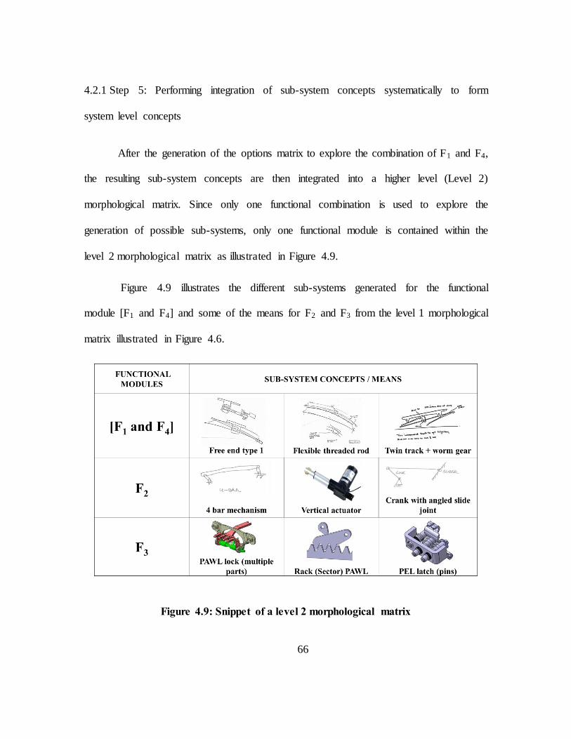
66
4.2.1 Step 5: Performing integration of sub-system concepts systematically to form
system level concepts
After the generation of the options matrix to explore the combination of F1 and F4,
the resulting sub-system concepts are then integrated into a higher level (Level 2)
morphological matrix. Since only one functional combination is used to explore the
generation of possible sub-systems, only one functional module is contained within the
level 2 morphological matrix as illustrated in Figure 4.9.
Figure 4.9 illustrates the different sub-systems generated for the functional
module [F1 and F4] and some of the means for F2 and F3 from the level 1 morphological
matrix illustrated in Figure 4.6.
Figure 4.9: Snippet of a level 2 morphological matrix

67
The level 2 morphological matrix (Figure 4.9) contains the remaining functions
(F2 and F3) and their corresponding means duplicated from the level 1 morphological
matrix because only one functional combination (F1 and F4) is used to generate sub-
system concepts. Therefore the remaining functions and their corresponding means
remain unchanged from the level 1 morphological matrix.
The function F2 is then combined with the functional module [F1 and F4]. This
results in the coupling of the 4 bar mechanism with the lead screw driven curved tracks.
As the sub-system concepts developed for the functional module [F1 and F4] are for a
power-assisted movement mechanism driven by a lead screw, the potential for using a
vertical actuator is also explored. However, the use of a 4 bar mechanism mounted on a
curved track could draw direct parallels with existing seating mechanisms. Therefore, the
use of a 4 bar mechanism is explored in conjunction with the sub-system concepts
generated for the functional module [F1 and F4].
The use of locking mechanisms is then explored to identify how the 4 bar
mechanism could be ideally controlled while enhancing the structural integrity of the
system to cater to the crash load requirements that the design would be subjected to in
real world applications.
As the design of the lead screw and the curved track required a load bearing
member to transfer the load away from the sub-system concepts illustrated in Figure 4.8
and Figure 4.9, it was not immediately apparent how a simple structural change could be
effected so that the system could potentially meet the crash load requirement

68
specifications. Therefore, this perspective was found to be limited in application, and
other options were subsequently explored using different functional combinations and
additional options matrices to generate system concepts using perspectives.
The process followed in generating the system concepts is summarized in Figure
4.10, beginning with the Level 1 morphological matrix. Figure 4.10 illustrates the options
matrices and the higher level morphological matrices that were generated to form system
concepts.
4.2.2 Step 6: Iterate to identify alternatives
As the process followed to the generation of system concepts using the method
initially led to a standstill without generation of a feasible system concept, different
functional combinations and means were used to explore the design space using different
perspectives. A number of potential functional combinations were explored and
additional options matrices were generated in the search for system concepts.
4.3 Summary of IIG method
The Integrated Idea Generation (IIG) method proposed in the preceding chapter is
applied in the design of a seat mechanism. The steps leading up to the use of the IIG
method to develop concepts are outlined. The various steps of the IIG method that are
employed are then explained.

69
Figure 4.10: Demonstration of the IIG method followed to generate system concepts

70
Although the IIG method proved to be helpful, it is important to identify if the
proposed method can be easily employed by designers. Therefore, an analysis of the
method’s usability was performed, as explained in the next chapter.

71
CHAPTER FIVE
TESTING AND ANALYSIS OF THE IIG METHOD OF CONCEPT GENERATION
The usefulness and the usability of the IIG method are evaluated through two user
studies on undergraduate and graduate students at Clemson University. Additionally,
interviews were conducted with some users of the traditional morphological matrix
method of concept generation and users familiar with the IIG method. Some feedback for
the IIG method was also obtained from industry sources. The data obtained from these
various sources and methods are presented in this chapter.
The first user study was a pilot study. The data and observations made during the
study were used in the design and execution of the second study. The key differences
between the two studies are summarized in Table 5.1.
5.1 User Study 1
5.1.1 Objective
The user study was conducted as an exploratory pilot study to evaluate the quality
and level of design detail of system level concepts generated using a traditional
morphological chart approach and using the IIG method. The results of the study will be
used to understand the usability and usefulness of the IIG method compared to the
morphological matrix method.

72
Table 5.1: Differences between User study 1 and User study 2
User Study 1 User Study 2
Objective Exploratory study to understand
the usability and usefulness of the
IIG method compared to the
morphological matrix method
To evaluate the level of design
detail and quality of concepts
generated using the IIG method
and the morphological matrix
method
Participants Two groups of 10
participants each
Each group split into 5
participants for each
method
One group of 10
participants
Group split into 5
participants for each
method
Design task Design of a burrito folding
mechanism
Design of a seat chassis
mechanism
Design of
study
Location – Controlled
environment
Time allowed – 60 minutes
for sketching, fixed time
slot
Information provided –
Detailed description of both
methods
Location – Participants
allowed freedom to take
study home
Time allowed – 90
minutes for sketching, 90
consecutive minutes
imposed, with a small
break in between, time
slot was not fixed
Information provided -
Concept of innovation
challenges not included to
reduce complexity

73
5.1.2 Participants
The participant groups were undergraduate students in freshman and sophomore
year, and graduate students. The groups had 10 participants each.
The particular user study groups were selected for the following reasons:
Both user groups were currently being trained as part of their coursework on
general idea generation methods (undergraduate students) and concept generation
during engineering design (graduate students). This ensured that the participants
had some background in idea generation, enabling them to perform well in the
user study.
The user groups were willing to take part in the study
The selection of the specific user groups allowed the user study to be conducted
readily in a controlled environment that did not require any additional effort on
the part of the users in terms of schedule or travel.
5.1.3 Expected Observations
1. The level of design detail in concepts generated using the IIG method is expected
to be greater than the level of design detail in concepts generated using the
morphological matrix method.
2. The quality of concepts generated using the IIG method is expected to be greater
than the quality of concepts generated using the morphological matrix method.

74
3. Time taken to generate system level concepts using the IIG method is expected to
be greater than the time taken to generate system level concepts using the
morphological chart method.
4. The quantity of system level concepts generated using the IIG method is expected
to be lesser than the quantity of system level concepts generated using the
morphological chart method.
5.1.4 Design of User Study 1 (Pilot Study)
The study was conducted independently for both user groups – undergraduate
students and graduate students.
Each of these groups was then split into two sections – one section to exercise the
morphological chart method, and one section to exercise the IIG method.
The students signed a voluntary informed consent agreement letter to participate
in the study. They were informed that their participation was not mandatory, and
that they would not be penalized in any manner for their non-participation or non-
completion of the study.
A presentation of the concept generation method (the relevant method pertaining
to each group) was given to the students for 15-20 minutes.
o The presentation included an overview of the concept generation method
with explanation of how the design problem statement, the list of
requirements, functional model, and idea generation methods were used to

75
generate the morphological charts. (A morphological chart serves as the
basis for both the concept generation techniques being studied.)
o The presentation described the concept generation method using the
morphological chart technique and the IIG method to the appropriate user
group sections. The participants were encouraged to ask questions to
ensure their understanding of the method being presented.
o A hard copy of the presentation was provided to each participant for them
to refer back to any section of the presentation at their convenience if they
so required.
o The presentation also explained what was expected of the students from
the user study. They were asked to generate system level conceptual ideas
from a morphological chart that contained fragmented ideas as in a typical
morphological chart. The morphological chart was provided to them and
was also displayed on a large 40” screen during the study for easy reading.
A packet containing documents relevant to the user study was handed out to each
participant before the presentation. The documents contained in the packet are
provided in Appendix C. Each student were provided with the following
documents (hard copy):
o A copy of the presentation
o List of requirements (single page)

76
o Function model containing 6 individual functions that the system was
required to perform with the explanations of these functions also provided
(single page)
o Morphological chart containing the individual functions and 4 ideas to
fulfill each function. (1 function only had 3 ideas compared to 4 ideas for
all the other functions.)
o Templates for the participants to draw sketches (both sections) and blank
templates for options matrices and higher level morphological charts (for
IIG method group only)
The participants were asked to sketch their system level conceptual ideas for 60
minutes after the end of the presentation.
5.1.5 Method of Analysis
The concepts generated were independently evaluated by 2 raters.
Two metrics were used to evaluate each concept – quality of concept and level of
design detail of concept.
Each metric was rated on a 1-3-9 scale to correspond to low-medium-high rating.
A definition of each metric and guidelines for scoring the concepts were given to
each rater.
The independent evaluations were compared against each other and the initial
inter-rater agreement was evaluated.

77
The discrepancies between the obtained results were discussed and resolved to
produce a single rating that was acceptable for both raters.
5.1.6 Results
Total number of concepts generated across both user groups : 38
Number of concepts generated using the morphological chart method : 26/38
Number of concepts generated using the IIG method : 12/38
5.1.6.1 Inter-rater agreement
Percentage agreement on “Quality” : 81.57% (31/38)
Percentage agreement on “Level of Design detail” : 94.74% (36/38)
The initial ratings of raters for the user study are provided in Table 5.2.
Table 5.2: Distribution of initial ratings of raters 1 and 2 for user study 1
Rater Metric
Initial rating
Total 1 3
MM IIG MM IIG
Rater 1 Quality 20 12 6 0 38
Level of design detail 24 12 2 0 38
Rater 2 Quality 22 11 4 1 38
Level of design detail 26 12 0 0 38

78
The distribution of the corrected ratings given for the metrics “Quality” and
“Level of design detail” for user study 1 is plotted in Figure 5.1.
Figure 5.1 illustrates that there is a larger number of concepts rated 3 for “quality” which
were generated using the morphological matrix method compared to the IIG method,
contrary to the expectations. The full results of user study 1 are provided in Appendix D.
5.1.7 Conclusions
Based on the data obtained from the study, observations during the study and
interaction with the participants during the study, the following conclusions are drawn:
1. No significant conclusions can be made regarding the effectiveness of the IIG
method or the morphological matrix method.
The number of good quality concepts and number of concepts with good
design detail was low. Therefore, an effective comparison could not be drawn
between the methods.
2. The confidence of the raters in the assessment of the perceived quality of the
concepts generated is significantly influenced by the level of design detail of the
concepts.
Whereas some concepts could be easily understood in terms of design
intent, some of the concepts generated had little design detail, making it difficult
to interpret the design intent, thus reducing confidence in the raters’ assessment of
the quality of the concepts.

79
Figure 5.1: Plot of the ratings for user study 1

80
3. The IIG method is more difficult to understand compared to the morphological
matrix method.
This conclusion is based on the observation that it took a while for the
participants to begin making functional pairs and start sketching out ideas during
the study. A lot of time was spent referring to the hard copy of the presentation,
and clarifying, the steps of the IIG method with the facilitator of the study. Also,
the participants opted to combine functions without spending a reasonable amount
of time trying to understand why a particular functional combination may be
beneficial, which was reflected by the generation of sub-system concepts that had
little design detail added to the means from the morphological matrix that was
presented to them.
4. Too much information was presented for the study for the participants to process
and use effectively
This conclusion is based on the observation during the study of
participants using only some specific information from the set that was provided.
For example, some participants used only the morphological matrix and the
templates provided, some participants referred to the functional model document,
while almost all the participants ignored the list of innovation challenges and the
requirements list. Some participants also seemed to struggle with arranging all the
information provided to use them during the sketching stage.
5. More than 60 minutes was required to generate concepts using the IIG method.

81
This conclusion is based on the observation of the sketches generated
where although a number of sub-system concepts were developed, the number of
system concepts were between 0 and 2. This was also echoed by some of the
participants asking for additional time to generate system concepts as they had
spent all 60 minutes generating sub-system concepts.
6. Conducting the user study during business hours in the University placed time
pressure on the students
Although the participants for the user study were available during the
hours requested to conduct the user study, they were under pressure to reach the
study location on time and for other appointments post completion of the study. A
small number of participants showed up close to 5 minutes late and some
participants constantly glanced at their watches during the study in preparation to
leave precisely at the end of the stipulated time.
7. The expected observations from the study were in line with the results obtained.
a. The time taken to generate system concepts using the IIG method was
greater than the time taken to generate system concepts using the
morphological matrix method.
b. The number of system concepts generated using the IIG method were
lower than the number of system concepts generated using the
morphological matrix method (12/38).

82
5.2 User Study 2
The objective of the user study 2 was similar to user study 1 – to evaluate the
quality and level of design detail of the concepts generated using the IIG method and the
morphological matrix method. The design and execution of user study 2 was also similar
to user study 1. However, based on the conclusions and observations from user study 1,
the following changes were made to the study compared to user study 1.
1. Objective: Same as user study 1
2. Participants: One group of 10 graduate students participated in the study. They
were split evenly, with one group exercising the morphological matrix method
and second group using the IIG method to generate concepts. This was done to
a. reduce the amount of variance between the participants
b. take advantage of the greater understanding of engineering principles
among graduate students compared to undergraduates in their first year
and sophomore years
c. to improve the chances of the participants obtaining a better understanding
of the concept generation methods
3. Expected observations: Same as user study 1
4. Design of user study: The design of the study was altered in the following manner
taking into consideration the observations and conclusions of user study 1.
a. The amount of time provided for participants to sketch their ideas was
increased from 60 minutes to 90 minutes.

83
b. The concept of using innovation challenges was removed so that the focus
of their efforts could be to simply generate details using functional
combinations.
c. The participants were not required to be in a specific location to take part
in the study. They were allowed to spend 90 consecutive minutes at their
own convenience at any suitable location and to take a short break in
between. They were given a week to return the sketches generated. This
was intended to relieve the time pressure that some students faced during
user study 1 and to allow the participants to spend more time to
understand the IIG method before using it to generate concepts.
5. Method of analysis: Same as user study 1
5.2.1 Results
Total number of concepts generated using IIG method : 17
Total number of concepts generated using morphological matrix method : 21
Total number of concepts generated : 38
5.2.1.1 Inter-rater agreement calculation between Rater 1 and Rater 2
Percentage agreement on “Quality” : 71.05% (27/38)
Percentage agreement on “Level of design detail” : 78.95% (30/38)
The initial ratings of raters for the second user study are provided in Table 5.3.

84
Table 5.3: Distribution of initial ratings of raters 1 and 2 for user study 2
Rater Metric
Initial rating
Total 1 3
MM IIG MM IIG
Rater 1 Quality 11 12 10 5 38
Level of design detail 12 14 9 3 38
Rater 2 Quality 16 12 5 5 38
Level of design detail 13 13 8 4 38
5.2.2 Corrected results
The differences in the ratings for both metrics between the two raters were
discussed and a rating that was acceptable to both raters was given for each of the distinct
values (see Table 5.4).
Table 5.4: Distribution of ratings for user study 2
Metric
Rating
Total 1 3
MM IIG MM IIG
Quality 14 12 7 5 38
Level of design detail 12 15 9 2 38

85
The distribution of the corrected ratings given for the metrics “Quality” and
“Level of design detail” is plotted in Figure 5.2. The full results of user study 2 are
provided in Appendix D.
5.2.3 Conclusions
The following conclusions were made based on the obtained results.
1. The quality and level of design detail of the concepts were more closely related to
the individual performance of users rather than the methods being used.
The ratings for both the metrics for the concepts generated using the IIG
method and the morphological matrix method are sparsely distributed and seemed
to be clustered where present.
2. No significant comparisons can be made between the effectiveness of either
method based on the results of the study.
The number of concepts with ratings higher than 1 for either of the metrics
are comparable for both the methods. Therefore, with the information obtained
from this study, it is difficult to establish which of the two methods is more
effective.

86
Figure 5.2: Plot of the ratings for user study 2
87
3. The low number of concepts with a good rating for the metric “Level of design
detail” adversely affected the raters’ confidence in their assessment of the quality
of the concepts as in user study 1.
Although the raters have a fair degree of confidence in the quality of the
concepts generated, the judgment of perceived quality of the concepts was still
not sufficiently supported by the design intent communicated through the
sketches.
4. The number of concepts that were rated higher than 1 for either metric was
significantly lower than expected.
Although the number of concepts that scored higher than 1 in either metric
improved from user study 1, the overall number was below expectations. This
could be due to a number of possible factors including the lack of understanding
of the methods, complexity of the design problem, design of the user study, use of
a participant group that lacked sufficient training, lack of design experience of
participants, or other factors such as external pressure or personal motivation.
5.3 Interviews
5.3.1 Objective
In order to gather a more detailed and less structured feedback from the users of
the IIG method and the morphological matrix method, and to understand the results of the

88
user studies, a set of interviews were conducted. The interviews were expected to provide
deeper insights into the thoughts of the users in the use of both the methods and
understand their difficulties using either method.
5.3.2 Participants
Two interviews each were conducted with users familiar with the morphological
matrix method and the IIG method of concept generation. Additionally, 2 more
interviews were conducted with practicing designers from industry who were familiar
with the IIG method of concept generation. The transcripts of all the interviews are
provided in Appendix E.
5.3.3 Conclusions from the interviews with Morphological matrix users
1. The morphological matrix method of generating system concepts is a simple and
powerful method of concept generation.
2. It is very easy to understand and use.
3. It is especially suited for simple design problems where a potential system
concept is easy to visualize.
4. It allows a user to immediately draw connections between means and quickly
generate system concepts when the design task is simple and the means within the
morphological matrix is easy to understand.

89
5. It is a method that is suitable for persons comfortable with developing a high level
concept at first and then generating design detail based on the components being
used in the system.
6. It can sometimes be overwhelming for a novice designer to use a morphological
matrix when the number of functions and means populated within the
morphological matrix are large. This is in line with existing literature on the size
and complexity of morphological matrices affecting the concepts generated [31].
7. It allows the designer the freedom to choose any path in the generation of design
alternatives. Therefore, the method is not restrictive or prescriptive. However,
some users feel that providing some guidelines to the users in terms of where to
direct their attention and beginning the concept generation process by starting
with a subset of the functions and means listed can be advantageous in some
cases.
8. Using the morphological matrix method can result in the assumption that the
means must be combined with each other in the order of the functions listed. The
realization that breaking the order of combination of means is possible and that it
results in the generation of additional ideas may not always be apparent to users.
9. Users are confident that they will be able to make a confident judgment on the
quality of the concepts generated using the morphological matrix method with
respect to the feasibility of the concepts based on the potential to fulfill the
functional and non-functional requirements of the system.

90
5.3.4 Conclusions from the interviews with the IIG method users
1. The IIG method is not as easy to understand as the morphological matrix method.
It takes a little longer to understand how to effectively use the method.
2. The IIG method is not as intuitive as the morphological matrix method in
generating system concepts for simple systems. However, it may be beneficial in
the design of more complex systems where a greater understanding of the
problem is achieved by generating sub-system details and working a way towards
achieving a system concept.
3. The IIG method is suited for users who prefer to start with smaller subsets of a
large design task and generate system concepts based on the understanding of the
components of the system.
4. The focus of the IIG method on the use of pairwise functional combinations may
prevent the users from identifying simple concepts that may be found using the
morphological matrix method.
5. The choices of functional combinations and the means can drive the selection of
subsequent functional combinations and means used to generate system concepts.
Therefore, there is a potential that some good system concepts may not be
identified.
6. It is not always easy to identify which functions should be paired together to
generate sub-systems.

91
7. It takes longer to develop system concepts using the IIG method compared to the
morphological matrix method.
8. The IIG method makes designers realize that the order of combinations of means
and functions influence the concepts generated.
9. The IIG method encourages designers to break the assumption that the functions
listed in the morphological matrix is hierarchical or sequential.
10. The IIG method allows the designers freedom to generate concepts, but also
provides some direction to novice designers on how to tackle a large or complex
problem step by step. However, some users might find this method too
prescriptive or rigid.
11. The users of the IIG method feel more confident in their assessment of the quality
of the concepts generated with respect to the feasibility of the concepts based on
the potential to fulfill functional and non-functional requirements.
5.3.5 Conclusions from the interviews with designers in industry
1. The IIG method forces the designer to consider a large number of possible
concepts rather than restricting themselves to a limited few.
2. The IIG method can be used to generate system concepts in a reasonable amount
of time.
3. It is particularly useful where systems have several key functions that need design
and development.

92
4. The generation of a morphological matrix may be challenging because designers
may have doubts regarding how many of the means generated may be useful at
the system level. Therefore, the use of a morphological matrix method or an IIG
method may not always be practically possible.
5. The IIG method helps experienced designers because it allows them to open their
minds and generate concepts that are outside their paradigm. The IIG method also
helps a novice designer because the more experienced designers can educate the
novice designers and improve their understanding of the design task and the
design space.
6. The innovation challenges used in the IIG method forces designers to challenge
their paradigms.
7. The effective use of the IIG method or the morphological matrix method depends
on the time constraints faced by the design team. Intense time pressures may
result in simply tweaking existing designs rather than using a method to explore
the design space in more detail.
8. The IIG method allows the designers to develop secondary functions that may not
be at the forefront of designers’ minds during concept generation.
5.4 Conclusions from the user studies and interviews
The following conclusions were made based on the results and observations from
both the user studies and the feedback obtained from the interviews conducted.

93
1. The IIG method and the morphological matrix method are useful methods of
concept generation. Their usefulness depends on the nature of the design task and
the personal preference of the designers (some designers prefer to generate high
level concepts and generate details within the scope of the generated system
compared to others who like to generate system concepts by building on the
details of smaller sub-systems).
2. The IIG method seems to perform better among designers in industry as they
seem to be able to generate much more details with respect to interfaces between
components, the potential compatibility and ramifications of the coupling of
specific functions, or potential for different geometric layouts of combinations for
the same set of means. This is in line with existing research findings where it is
argued that inexperienced designers tend to overlook deeper aspects of design
problems that are apparent to experienced designers [10]. The novice designers
may benefit better from the morphological matrix method by enabling them to
generate a high level concept easier.
3. It takes longer for a designer to understand and exercise the IIG method to
develop concepts. However, the concepts that are generated using the IIG method
may have a greater level of design detail once the use of the method is mastered.
The results of the user studies were not significant because the users of the IIG
method were not sufficiently trained on the use of the method. Therefore, the
results obtained were during the ‘break-in’ period where a greater understanding
94
of the method was being gained during its use, and the users were not proficient in
the use of the method.
5.5 Advantages and challenges of the IIG method based on testing and analysis
Based on the results of the user study and the feedback received from the
interviews, the IIG method has certain advantages and challenges.
5.5.1 Advantages of the IIG method
1. The IIG method allows the generation of system concepts that have greater design
detail (this is not conclusive, but suggestive based on the results of the
interviews).
2. It forces designers to think about different potential functional combinations and
orders of combinations of means to generate additional concepts and realize the
extent of the design space.
3. The use of innovation challenges forces designers to challenge their existing
paradigms and think differently to generate innovative designs.
4. The use of IIG method results in increased confidence in the designers’ judgment
of the feasibility of the concepts with regard to potential for fulfilling the
functional and non-functional requirements.
5. The IIG method provides guidance and direction to a novice designer who may be
overwhelmed by the large number of means or functions in a morphological
matrix.

95
6. The IIG method is more suitable for designers who prefer to generate system
concepts based on their detailed understanding of the sub-systems that make up
the system.
7. The IIG method provides a powerful, yet flexible tool that allows a designer the
freedom to generate a number of different concepts without being too
prescriptive.
8. The IIG method provides a link between high level system concepts and
generation of design details that is not addressed by the traditional morphological
matrix method. Although the morphological matrix is useful, the IIG provides an
additional step to perform detailed design.
9. The IIG method is suited to design tasks with special emphasis on key functions
that need design and development.
10. The IIG method may be suitable for use in other domains of application,
extending beyond the design of mechanical artifacts to provide support for
conceptual design as a domain independent design support tool.
5.5.2 Challenges of the IIG method
1. The IIG method is more difficult to understand and implement compared to the
morphological matrix method.
2. It takes longer to develop system level concepts using IIG method compared to
the morphological matrix method.

96
3. The morphological matrix method is more suited to simple design tasks and
novice designers who prefer to develop a high level conceptual idea first before
generating design detail.
4. The IIG method might be too prescriptive for some users to use it effectively.
5.6 Summary
Despite the challenges of the IIG method, it is a useful method for generating
system concepts. It is more difficult to understand and implement the IIG method
compared to the morphological matrix method, and sufficient training and practice is
required to generate the necessary proficiency required to use the method effectively to
generate good system concepts. It takes longer to generate system concepts using the IIG
method; but the concepts generated are expected to be of higher quality and to contain
greater design detail when the users are proficient in the use of the method. Also, the IIG
method can encourage designers to challenge their implicit assumptions and their
paradigms to generate radical concepts although simple design tasks could be more
intuitively performed using the morphological matrix method. Therefore, despite the
challenges of the IIG method, its use can be justified and promoted in industry.

97
CHAPTER SIX
CLOSURE: SUMMARY OF IIG METHOD AND FUTURE WORK
This chapter outlines how the proposed method relates back to the research
objective and the research questions that have been identified. A summary of the research
is then provided and some future work that can be done to build on this research has also
been identified.
6.1 Assessment of IIG method with respect to addressing the research questions
The IIG method was developed to address two research questions. An assessment
of the IIG method with respect to its ability to address the research questions is made in
this section.
6.1.1 Research Question 1:
What method can be employed to allow a designer to effectively navigate the
design space sufficiently without performing a full factorial combination of all the means
within a morphological matrix?
The IIG method proposes a filtering of the initial morphological matrix to identify
the means that clearly do not seem to meet requirements or seem feasible with respect to
safety, complexity, reliability, cost, or other similar parameters. This reduces the number
of combinatorial possibilities to explore by a substantial number.

98
Additionally, the IIG method facilitates the generation of design detail for a
number of functional combinations and encourages the exploration of different geometric
combinations for specific combinations of means. This facilitates a deeper understanding
of the potential within the design space as well as the limitations of the means identified.
This understanding of the means, coupled with the grouping of the means within the
morphological matrix, allows the designer to extrapolate the information generated
through the specific functional combinations, to postulate on the possible characteristics
of the combinations resulting from using other means. Therefore, a fair estimate of how
the design space can be exploited can be gained through the strategic use of some of the
means within the morphological matrix.
Therefore, the IIG method provides a method whereby a designer can effectively
navigate the design space represented within a morphological matrix sufficiently to
generate different system concepts. Thus the IIG method addresses research question 1.
6.1.2 Research Question 2:
What guidelines can be provided to designers to generate system concepts that
have sufficient design detail to make a confident judgment on the feasibility of the
concept with respect to the requirements and generate a rank ordered list of potential
system concepts?
Through the use of specific functional combinations and generation of design
detail pertaining to specific functional combinations using options matrices and
99
innovation challenges, the IIG method provides designers with a method to gain a
thorough understanding of the design space and each system concept that is developed.
The use of different combinatorial perspectives for combining means, exploring different
functional combinations and order of combinations, explicit capture of the engineering
judgment for all the combinations generated, and the generation of design detail for every
pairwise combinations of means explored combine to provide the designers with a lot of
information that can allow a designer to make a reasonable assessment of the feasibility
of the generated concepts with respect to requirements and with respect to each other to
create a rank ordered list.
The use of innovation challenges, functional combinations and encouragement to
explore different possible combinatorial possibilities facilitate the generation of
innovative designs, identify implicit assumptions, and also allow the designers to realize
the potential of the design space while generating the concepts.
Thus, the IIG method provides a method whereby a designer can generate
sufficient design detail to the generate concepts that allow a confident judgment of the
feasibility of the concepts with respect to requirements and to generate a rank ordered list
of concepts. Hence, the research question 2 is also addressed.
6.2 Summary of the research
Some limitations of the morphological matrices in supporting concept generation
are highlighted. This research addressed the identified limitations of the morphological
100
matrix through the development of an Integrated Idea Generation method that uses
functional combinations from within the morphological matrices, innovation challenges
and options matrices to generate conceptual designs. The IIG method was applied to the
design of a seat mechanism in collaboration with an industry partner to establish the
performance of the IIG method in industry and refine the method based on the findings.
Additional testing was performed to gain a deeper understanding of the method by
conducting user studies and interviews with novice designers and industry experts. The
results of the testing are used to establish the potential of the developed IIG method and
identify some of the challenges of using the method. However, despite the challenges
identified, the method appears to be a useful tool to augment the use of morphological
matrices in generating system level concepts.
Specifically, the major advantages and challenges associated with the IIG method
are the following:
1. The IIG method provides a link between the high level concepts generated using
morphological matrices and the generation of design details that is not addressed
by the traditional morphological matrix method of concept generation.
2. The IIG method helps the designers to visualize the entire design space using the
morphological matrices and specific sub-system design spaces defined by the
functional combinations using the options matrices.

101
3. The IIG method focuses designers’ attention on the design of small sub-systems
of a system to exploit the specific characteristics of the sub-systems in the design
of system concepts.
4. The innovation challenges used in the IIG method encourage designers to
consider different perspectives for combining means that are not apparent when
using a traditional morphological matrix method.
5. The most significant challenge with the IIG method is that it is more complex and
prescriptive compared to the morphological matrix method. While the prescriptive
nature can guide novice designers, it is more challenging to learn.
6. It takes a longer duration of time to generate system concepts using the IIG
method compared to the morphological matrix method.
7. The IIG method appears to be more effective for experienced designers compared
to novice designers, as they tend to generate more design detail for specific sub-
systems.
6.3 Future work
In chapter 3, six tasks were identified as required in order to completely address
the research gaps that were identified. However, the scope of this research was limited to
the development and some initial testing of the developed method. Therefore, in order to
completely address the research gaps identified, the remaining tasks need to be
completed. The tasks that need to be completed in future are as follows:
102
1. Validate the method with different users – novice and experienced designers.
2. Develop tools to support concept generation using the method.
3. Explore potential for use in different domains to make the method domain
independent.
4. Teach the method to designers; perform continuous assessment and refinement of the
method.
Based on the user studies and the interviews conducted, it is recommended to
perform validation of the IIG method by applying it to real-world design problems in
industry. This will allow a fair estimate of the performance of the method where it
matters most and help identify the potential challenges associated with the method. It
would also help develop a deeper understanding of the tools necessary to support the
method in industry.
Some software applications are currently being explored to provide support for
the method including an ontological framework to support concept generation in general
from population of a morphological matrix up to the generation of design concepts and
performing selection from the design alternatives. A deeper understanding of the IIG
method based on a more widespread application of the method is required to be able to
judge the potential of the method in other domains.

103
APPENDICES

104
Appendix A – Concept sketch document
Figure A - 1 illustrates the concept sketch template to document the
characteristics of the individual means populated within a morphological matrix. The
template documents a sketch of the idea, a brief description, the identified pros and cons
of the idea, and the key components that form part of the idea. These are documented for
all the means within the morphological matrix as well as all the sub-system concepts and
the system concepts generated during concept generation.
Figure A - 1: Concept sketch template to document characteristics of
means/concepts

105
Appendix B – Set of requirements for seat mechanism (provided by JCI)

106

107

108

109

110
Appendix C – Packet of documents from user studies 1 and 2
Appendix C-1: User Study 1 – Packet of documents provided to users of the traditional
morphological matrix method
The document packet provided to the participants of the morphological matrix
section of user study 1contained the following documents along with 7 copies of the
concept sketch template illustrated in Figure A - 1 of Appendix A. Additional template
documents were provided for participants who required more.
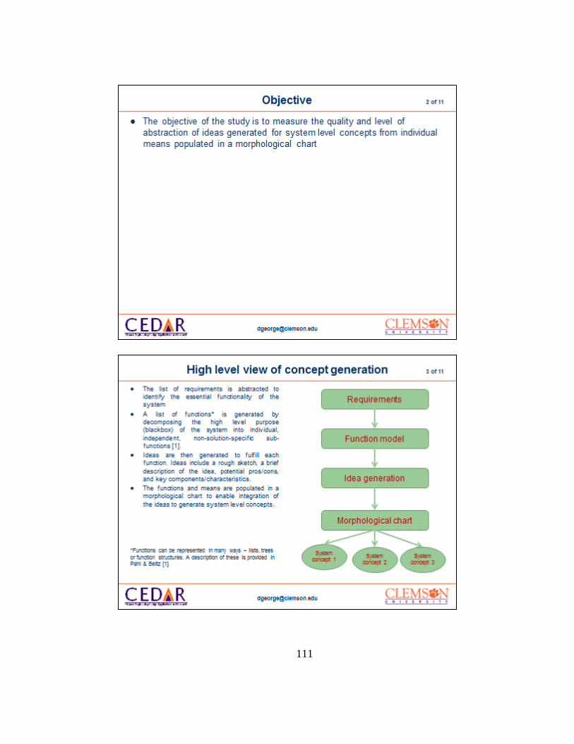
111

112

113

114

115

116

117

118
Appendix C-2: User Study 1 – Packet of documents provided to users of the IIG method
The document packet provided to the participants of the IIG section of user study
1contained the following documents along with 7 copies of the concept sketch template
illustrated in Figure A - 1 of Appendix A. Additional template documents were provided
for participants who required more, including additional copies of the template
documents listed in this section.

119

120

121

122

123

124
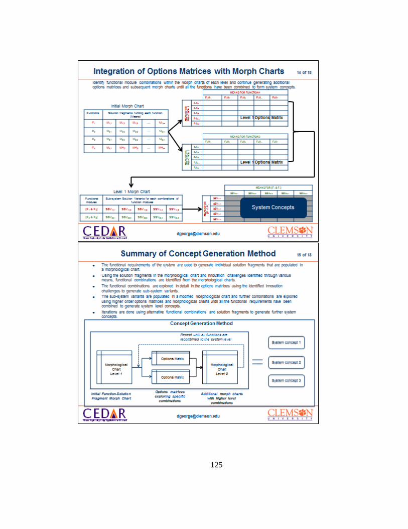
125

126

127

128

129
130
Appendix C-3: User Study 2 – Packet of documents provided to users of the traditional
morphological matrix method
The document packet provided to the participants of the morphological matrix
section of user study 1contained the following documents along with 7 copies of the
concept sketch template illustrated in Figure A - 1 of Appendix A. Additional template
documents were provided for participants who required more.

131

132

133

134

135

136

137
Appendix C-4: User Study 2 – Packet of documents provided to users of the IIG method
The document packet provided to the participants of the IIG section of user study
1contained the following documents along with 7 copies of the concept sketch template
illustrated in Figure A - 1 of Appendix A. Additional template documents were provided
for participants who required more, including additional copies of the template
documents listed in this section.

138
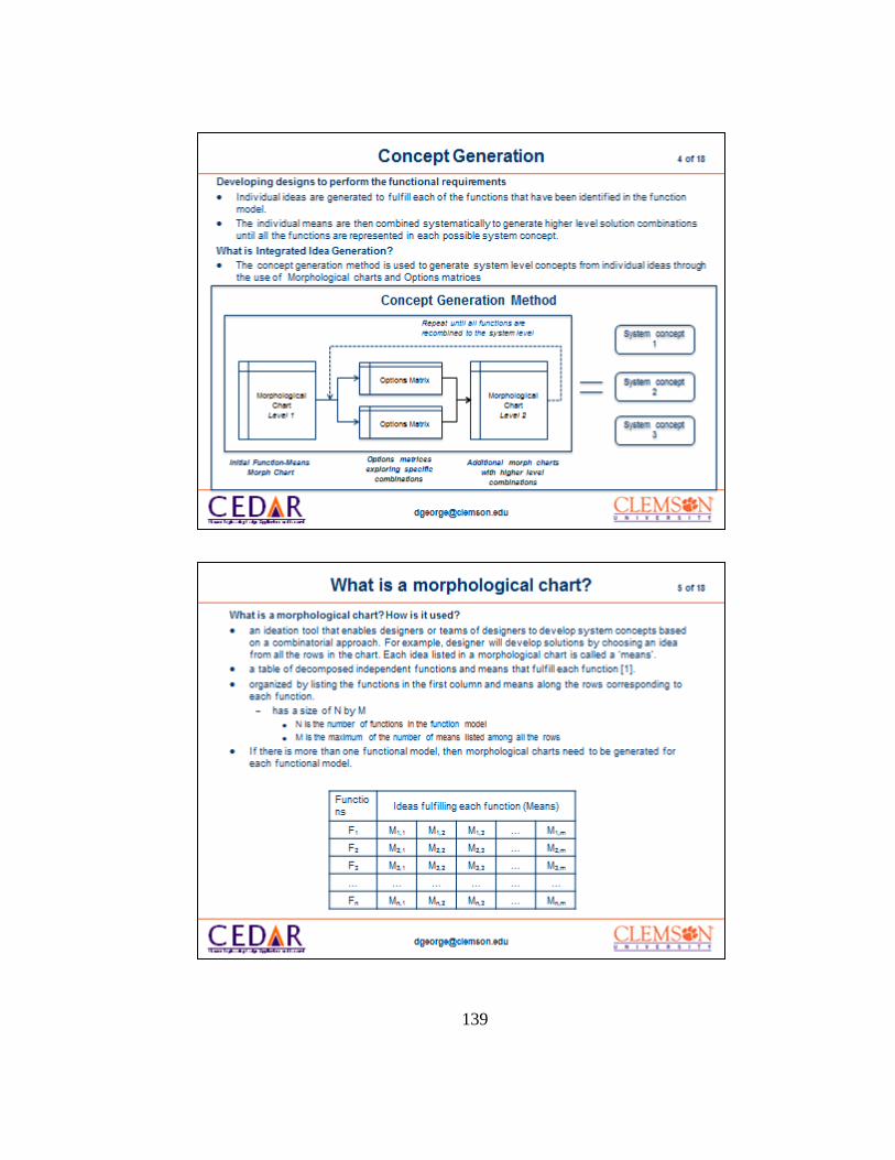
139

140

141

142

143

144

145

146

147

148
Appendix D – Results of the user studies
RESULTS OF USER STUDY 1
Key
Gro
up
Qu
ality
Corr
ecte
d
Qu
ality
met
ric
Lev
el o
f
Ab
stra
ctio
n
Corr
ecte
d L
evel
of
ab
stra
ctio
n
met
ric
RATER 1 RATER 2 RATER 1 RATER 2
A-001 MC 1 1 1 1 1 1
A-002 MC 1 1 1 1 1 1
A-003 MC 1 3 3 1 1 1
A-004 MC 1 1 1 1 1 1
A-005 MC 1 1 1 1 1 1
A-006 MC 3 3 3 1 1 1
A-007 MC 1 1 1 1 1 1
A-008 IIG 1 3 3 1 1 1
A-009 IIG 1 1 1 1 1 1
A-010 MC 1 1 1 1 1 1
A-011 MC 1 1 1 1 1 1
A-012 MC 1 1 1 1 1 1
A-013 MC 1 1 1 1 1 1

149
Key
Gro
up
Qu
ality
Corr
ecte
d
Qu
ality
met
ric
Lev
el o
f
Ab
stra
ctio
n
Corr
ecte
d L
evel
of
ab
stra
ctio
n
met
ric
A-014 MC 1 1 1 1 1 1
A-015 MC 1 1 1 1 1 1
A-016 MC 3 1 3 1 1 1
A-017 MC 3 1 3 1 1 1
A-018 MC 1 1 1 1 1 1
A-019 MC 1 1 1 1 1 1
A-020 MC 3 3 3 3 1 3
A-021 MC 3 1 3 3 1 3
A-022 MC 1 1 1 1 1 1
A-023 MC 1 1 1 1 1 1
A-024 MC 1 3 3 1 1 1
A-025 MC 1 1 1 1 1 1
A-026 MC 1 1 1 1 1 1
A-027 MC 3 1 3 1 1 1
A-028 MC 1 1 1 1 1 1
A-029 IIG 1 1 1 1 1 1
A-030 IIG 1 1 1 1 1 1

150
Key
Gro
up
Qu
ality
Corr
ecte
d
Qu
ality
met
ric
Lev
el o
f
Ab
stra
ctio
n
Corr
ecte
d L
evel
of
ab
stra
ctio
n
met
ric
A-031 IIG 1 1 1 1 1 1
A-032 IIG 1 1 1 1 1 1
A-033 IIG 1 1 1 1 1 1
A-034 IIG 1 1 1 1 1 1
A-035 IIG 1 1 1 1 1 1
A-036 IIG 1 1 1 1 1 1
A-037 IIG 1 1 1 1 1 1
A-038 IIG 1 1 1 1 1 1
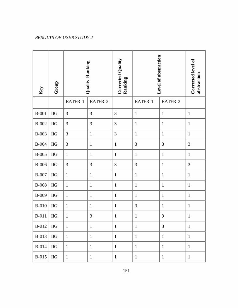
151
RESULTS OF USER STUDY 2 K
ey
Gro
up
Qu
ality
Ran
kin
g
Corr
ecte
d Q
uality
Ran
kin
g
Lev
el o
f ab
stra
ctio
n
Corr
ecte
d lev
el o
f
ab
stra
ctio
n
RATER 1 RATER 2 RATER 1 RATER 2
B-001 IIG 3 3 3 1 1 1
B-002 IIG 3 3 3 1 1 1
B-003 IIG 3 1 3 1 1 1
B-004 IIG 3 1 1 3 3 3
B-005 IIG 1 1 1 1 1 1
B-006 IIG 3 3 3 3 1 3
B-007 IIG 1 1 1 1 1 1
B-008 IIG 1 1 1 1 1 1
B-009 IIG 1 1 1 1 1 1
B-010 IIG 1 1 1 3 1 1
B-011 IIG 1 3 1 1 3 1
B-012 IIG 1 1 1 1 3 1
B-013 IIG 1 1 1 1 1 1
B-014 IIG 1 1 1 1 1 1
B-015 IIG 1 1 1 1 1 1

152
Key
Gro
up
Qu
ality
Ran
kin
g
Corr
ecte
d Q
uality
Ran
kin
g
Lev
el o
f ab
stra
ctio
n
Corr
ecte
d lev
el o
f
ab
stra
ctio
n
B-016 IIG 1 1 1 1 1 1
B-017 IIG 1 3 3 1 3 1
B-018 MC 3 1 1 3 3 3
B-019 MC 3 1 3 3 3 3
B-020 MC 3 1 1 3 3 3
B-021 MC 1 3 1 3 3 3
B-022 MC 3 3 3 3 3 3
B-023 MC 3 1 1 3 1 3
B-024 MC 1 1 1 1 1 1
B-025 MC 3 1 3 3 1 3
B-026 MC 1 1 1 1 1 1
B-027 MC 1 1 1 1 1 1
B-028 MC 1 1 1 1 3 1
B-029 MC 3 3 3 3 3 3
B-030 MC 3 3 3 3 3 3
B-031 MC 1 1 1 1 1 1
B-032 MC 1 1 1 1 1 1
B-033 MC 1 1 1 1 1 1

153
Key
Gro
up
Qu
ality
Ran
kin
g
Corr
ecte
d Q
uality
Ran
kin
g
Lev
el o
f ab
stra
ctio
n
Corr
ecte
d lev
el o
f
ab
stra
ctio
n
B-034 MC 3 3 3 1 1 1
B-035 MC 1 1 1 1 1 1
B-036 MC 1 1 1 1 1 1
B-037 MC 1 1 1 1 1 1
B-038 MC 3 1 3 1 1 1

154
Appendix E – Transcripts of interviews
Appendix E-1: Transcripts of interviews with users of the Morphological matrix method
of concept generation
USER 1
Number of years as an engineering designer: 2
Educational qualifications: MS degree, Mechanical Engineering.
Interviewer: So the interview is to gather your thoughts on the use of morphological
charts to generate conceptual ideas. I will ask you about 11 questions, so it should not
take longer than half an hour. So, let me ask you, how many years of experience do you
have as an engineering designer?
User 1: As an engineering designer, I would say 2 years. That was 2 years of my masters
education and the last few months I have been working on my Ph.D. And it has been
totally design based - solid mechanics and finite elements. So I would say 2 years of
design experience.
Interviewer: So I guess that answers a question about your educational experience also.
Are you familiar with the method of generating system level concepts using
morphological charts?
User 1: Yes, I am aware of the method.
Interviewer: Have you used the method to generate any system concepts?

155
User 1: I have used the method a couple of times. Once when I was taught the method in
class and I had participated in a user study as a part of the ME 870 class that I have
taken at Clemson. So yes, I have experience of working with morphological charts.
Interviewer: So do you think you have a good understanding of the morphological chart
method?
User 1: Yes, I would say that because I could use the method and generate design
concepts using morphological charts. So yes I would say I have.
Interviewer: So, having used the method, can you provide some thoughts on the method?
What do you think of the method in terms of its usefulness, if it makes sense, if it may be a
little complicated, if it is time consuming, etc.? What are your general thoughts?
User 1: The general thoughts are, to a person who is not at all aware of the method, I
personally think that if you attend a 10 or 20 minute basic introductory session to that
method, the person gets familiarized with the method. I think it’s a simple and powerful
method. Also, all the options are out there in front of your eyes, and all you have to do is
combine those different options and come up with design concepts. You have the visual
aid necessary and the help necessary. So I think it is a very simple and powerful method.
Interviewer: Can you talk to me about some of the specific advantages that you have
found with this method? What do you think are some of the advantages and what have
you found?

156
User 1: Specifically, what I think is, if a designer is asked to come up with a design
concept, say specifically, a novel design concept for a dust bin shape or a linkage or a
mechanism, we need a starting point. If someone asks me to think and come up with a
design concept, it is very difficult to do so. What the morph chart does is, it gives me a
systematic breakdown of the entire design I am supposed to come up with in terms of
functions and for each of those functions, different means are given to me. And as a
designer, all I have to do with the morph chart is to understand what is presented to me
and come up with different combinations that seem most logical or most efficient to me as
a designer. So that simplifies my task a great deal, rather than giving a blank slate and
saying come up with design concepts. So I think that is a very elegant way of doing things
where you give the designer enough help so that he is not bogged down by coming up
with new concepts, whereas you also give him enough freedom, so that he can combine
different design functions or means to come up with his own solution. So I think there is a
nice balance in there, where you are giving enough freedom as well as the means.
Interviewer: So you think that the provision of that particular freedom is actually very
important, whereas while you have a method to go through, you also allow the person
freedom and that is very essential?
User 1: Yeah, that is very essential. Because often, what I think and that should be true
for most people, that coming up with something from a blank slate is very difficult. But
you need certain aid or starting point. That is a very important point that happens in this
morphological chart.

157
Interviewer: How do you think the morphological charts can help a novice designer? I
know you have answered some of that question. To sum up, I can say, you said it would
help you visualize the solution space, it provides a very good breakdown of the problem
into specific sub-systems, and it also gives you a systematic method which is very
powerful as well, and it gives you the freedom to design concepts. So is there something
specific, or something more that you want to add? Does anything else come to mind?
User 1: Building on that, especially when it comes to novice designers, maybe when you
may be don’t have too many ideas, as novice designers you might take more time to come
up with new concepts. At that time, this is very helpful to novice designers. Also, what this
might do is while coming up with design concepts, it might trigger new ideas, as in
design, there is this [I am not familiar with the terminology right now, something might
get triggered].
Interviewer: (interrupts) External stimuli?
User 1: Yes, exactly. External stimuli: even that might be one of the advantages.
Interviewer: What do you think are some of the challenges you have faced in using the
method. We have talked about the advantages, but are there any specific challenges that
you have faced?
User 1: Let me think. (pauses) One challenge that I can think of might be, if there are too
many functions in the given design, say 12 of them, in the end the designer might find it
difficult to consolidate all the means which he has chosen to come up with a design. That

158
might be a challenge. So I would say that too many functions in the morphological chart
might be a problem. Plus, if there are too many means brought into it, the designer might
get confused. So too many of those options, and of course too little would also be a
problem. So the challenge is the number of means and the number of functions that are
provided to the designer.
Interviewer: One of the advantages of using a morphological chart is that for each of
the functions, it allows you to explore and generate all the different possible ways in
which you can achieve that function. And because of that, the number of means that you
can generate for each of those functions can be very large. So even if you have only about
5 or 6 functions, you could potentially have anywhere between 5 and 30 or 40 different
means. This means that in the end, although your number of functions might be less, you
might end up with a very wide morphological chart that has a large number of means. In
that case, how would you go about looking at the morph chart and say, where do I begin?
Does it begin to boggle your mind?
User 1: It won’t be very mind numbing for me, but it would take more time for me to
absorb the information. Because, for every function, if we have for example, 15 different
means, then I have to go carefully go through each and every mean and go through it
step by step. So that would slow down the process, yes, and I can handle that as a
designer. But that would take more patience and more time on my part, more effort. I’ll
have to go through it slowly, absorb the information, make a comparison and then come
up with concepts.

159
Interviewer: So, building on that, when you have such a large number of means on each
row of the morph chart corresponding to each function, do you think it makes sense to
take a look at the first row of functions, and let’s say for example you have 30 different
means, does it make sense for you to go ahead and say, “This, this, this and this don’t
make an awful lot of sense. So let’s keep that aside for the time being and look at the
rest”? Does it make sense to have some sort of filtering or pruning of the morph chart?
User 1: Yeah, definitely. I would do that. Like, using some kind of decision making,
eliminating the not-so-good or the bad options from those means, to me as a designer
(makes sense). Definitely, I would do that, as a designer, I would not want to use all 30
means and just make myself confused. So I would definitely eliminate those options which
don’t seem that good to me or which are bad, and I would narrow down the number of
means and then proceed from there.
Interviewer: When you’re using the morphological chart, do you think you give enough
thought to the realization that changing the order of functions within the morphological
chart can result in completely different solutions? For example, if you combine A, B, C,
D and E in that order and you combine C, D, B, E and A, now in a different order, do you
explicitly realize when you’re actually generating ideas within the morph chart, that
changing the order of combinations can give you different characteristics or different
attributes? Does it always play on your mind, the possible number of different
combinations that you may actually have?

160
User 1: Let me think (pauses). I had never given much thought to this point that we can
switch the functions, but now that I think of it, yes, I think if the order of functions is
switched, if I am asked to come up with designs, that would make a difference. But as a
designer, I have seriously not handled this case. So to be very honest, I am not sure what
kind of effect that would have on my mind while working with that. But, I do realize that it
is going to make a difference. But honestly, since I haven’t worked on it, I can’t really say
more.
Interviewer: Yeah, I understand. We talked about changing the order of functions, but it
is also possible that if you’re looking at two functions in that order, say function 1 and
function 2, two different means can be combined in a variety of different ways. So if
you’re trying to combine functions 1 and 2 in that order, and you’re combining means A
and B, A and B can be combined in different number of ways. There could be different
geometric combinations, one mounted on top of another, behind the other, in front of
another, diagonally opposite to another, etc. Do those kinds of situations also play on
your mind when you’re looking at combinations?
User 1: Yeah, definitely. That’s a point. If I’m given say two things, function A and
function B, how do I combine those things, that also does affect my mind. It will definitely
play on my mind, as to how they would combine. If I am supposed to come up with
designs, I would definitely at least provide one or two means, either put one on top of the
other, or side by side or something. I would definitely point that thing out. I wouldn’t
leave it like a grey area.

161
Interviewer: Right. But you realize that when you’re using the morphological chart,
these different combinatorial possibilities exist?
User 1: Yeah, yeah, absolutely.
Interviewer: So from the different concepts that you generate at the end of the method,
do you think you will be able to look at the concepts and be confident in your judgment of
whether these concepts can meet both your functional and non-functional requirements?
I’m not saying that they must absolutely meet, I’m saying, can you look at the ideas that
you generated and from that, based on the design detail that you’ve built into it, can you
make a confident judgment on whether they meet requirements? Can you say that “this
will meet the requirements for such and such a reason and because I have addressed all
these things?” Can you make a sound confident judgment on each of your solutions?
User 1: Yes, I think so. I definitely think I can do that because I have generated the
concepts. In the last question, like I said, while combining the functions, the “how” part
of it is going on in my mind. I will definitely be able to evaluate the concepts and say
confidently that “this does not seem to be a very good design” or that “this will meet or
this will not meet the functional requirements”. I think I can say this with confidence with
this method.
Interviewer: Building on that, after you create your list of concepts, can you based on
the design detail built into it, can you confidently create a rank ordered list of concepts?
So if you have ten, can you say, “this is definitely number 1, this is definitely number 2,

162
this and this may be tied for third place as they’re very similar” and you have four and
five. How confident will you be in actually assigning those rankings?
User 1: I would be pretty confident in assigning those rankings because I will be able to
provide some kind of evaluation. Even if you do it numerically, it’s going to be a little bit
subjective but yeah, given the functional requirements I will be able to evaluate the
designs and provide some kind of an order with that. I would rank them in the descending
order and I am confident I can do that based on the concepts I’ve generated using a
morphological chart.
Interviewer: Right, but the functions that are represented in the morph chart only
represent the functional requirements of the system, whereas a feasible concept must take
into account the functional and the non-functional requirements. This means that the
concepts you developed must not only meet the functions that you have addressed, but
also meet the non-functional requirements. Again, do you think that your rank ordered
concepts would be able to be translated with respect to their feasibility towards non-
functional requirements as well?
User 1: When answering this question, I was under the assumptions that those things are
also provided to me when I’m evaluating the solutions.
Interviewer: (interrupts) Yeah, they will be provided.
User 1: Yeah, absolutely. If the list is provided to me, then as per my experience, as a
novice, that is the best thing maybe that a novice designer can produce. But to the best of

163
my capability, I am pretty confident I can do the evaluation and come up with the ordered
list of concepts that I have generated.
Interviewer: So is there anything else that you want to add about the morphological
chart method or do you think you have covered it sufficiently?
User 1: I think pretty much yeah. I think I have pretty much covered all the things.
Interviewer: So now, going back to the previous question that I asked you about
feasibility, actually, one of the answers you provided to a question. You mentioned that
when there are a large number of functions, it becomes difficult for you to look at them
and combine all of them together.
User 1: Yeah.
Interviewer: In that respect, does it make sense for you to use the morphological chart,
but have someone give you a systematic method of maybe how you can use a
morphological chart whereby you say, “If you have ten functions, let them be there, but
take two functions together, explore different ways in which those two functions or the
means representing those functions can go together, generate some design detail to it,
and see how those additional functions can be added on to those.” Or how you can
generate sub-systems based on them and then provide some sort of combination in
between? Does that make sense?
User 1: Yeah, absolutely, that would be very helpful. I mean, especially when we are
handling large number of functions. That kind of training, or that kind of input, I would

164
definitely appreciate as a designer. And that would not only help me, but also enhance
the quality of designs that I would come up with as a designer.
Interviewer: How do you think it would enhance the quality of your designs?
User 1: Quality of the designs, as in, I had an idea that you could come up with sub-
systems and think of coupling those sub-systems. What then happens is that my entire
focus is not on the ten functions, I am only concerned with combining the two functions
and combining them in the best possible way and maybe in other few possible ways. Then
I can think of those sub-systems, then go to the next functions, say three and four, and
combine three and four with the one and two. So I can have a localized concentration on
the problem. So I am handling short or less piece of information. That helps me process
the information better as I am handling less number of things at once. So that would be
most certainly helpful and I think that is how the method should be introduced to the
designers, now that I think of it.
Interviewer: Great, so even in terms of exploring those functions in a coupled fashion,
does it make sense for us to say, and we can only provide a generic method, but can you
take a look at the list of functions and generically say “Think about the functions which
can logically go together?” For example, anti-mechanisms, that are opposite of each
other, if you have to take something forward, you have to stop it. If you have to move
something, you have to lock something. Does it make sense to you, if someone takes a
look at these different functional combinations in terms of how they can be coupled
logically, or how they can be coupled geometrically, or temporally, may be one happens

165
after another, does it make sense for me to give you an advice and say “if you have a lot
of functions, think about what makes sense to combine logically and look at them as
specific functional combinations?
User 1: Yeah, definitely. I mean, the morphological chart provides you with the visual
aid and the visual stimulus, but these kinds of things help me as a designer. It’s kind of a
stimulus, again, not giving too many specifics, so I have my freedom, so I also have a
direction. It definitely gives me a good direction to proceed. So I think that would most
certainly be helpful.
Interviewer: Building on that, when you’re looking at generation of specific sub-systems
in a morph chart and then using those sub-systems (to) generate further solutions and
then going about systematically to generate system level concepts, do you think that your
confidence in your ability to judge the quality and to generate the rank ordered concepts
will be better?
User 1: I think if I’m handling less functions and (generating) sub-systems and then
combining the sub-systems to come up with the final design concept, I would have more
confidence in that method. The reason being, while coming up with the designs, I have
analyzed all the means and the combinations in more detail with more thought into it. So
that would help me evaluate my designs better rather than the first method when I’m kind
of getting bogged down that I have ten more functions to work with, so it’s kind of
occupying my thought process. So I would be more confident handling the concepts that I

166
have come up with using the sub-systems method because I have spent more time, I have
evaluated the thing better and in more detail.
Interviewer: So one of the problems when looking at problems with generating concepts
using a functional combination is that compared to using a traditional morph chart
method, this might take a lot more time to actually get to a system concept because
you’re looking at specific sub-systems and how the sub-systems can go together. This is
going to take a lot longer than the morph chart. So how do you think the value of time
spent on both these things can match up?
User 1: First of all, if the designer is hundred percent motivated to come up with a
design, then spending more time using the second system shouldn’t matter because at the
end of this entire, more time consuming process, a designer is more confident of coming
up with high quality solutions. And, the designer may himself come up with more
solutions, so even if it is time consuming, if we consider the quality of the solutions that
are generated and if we consider the number of solutions that are generated using this
second method, at the end of the day, if we have to do some kind of a numerical
evaluation, assign some numerical cost to say, time and to the number of designs
generated, this second method is definitely more advantageous, because, if you do a cost
benefit analysis, the benefits of this method are more because you come up with high
quality solutions. Using the earlier method, we might have to go through more number of
iterations or may be give more inputs to the designers and eventually I think that the
second method is better.

167
Interviewer: So for a novice designer, it makes sense to, like you said, give some
direction as well to say, think about going in this direction or this direction?
User 1: Absolutely, absolutely.
Interviewer: OK, great. That basically concludes my interview. Thank you very much.
User 1: Thank you. It was fun.
USER 2
Number of years of experience as an engineering designer: 3 years
Highest educational qualifications: BS, Mechanical Engineering
User 2: This interview is to gather your thoughts on the use of morphological charts to
generate conceptual ideas.
Interviewer: Are you familiar with the method of generating system level solutions using
morphological charts?
User 2: Yes
Interviewer: Have you used the method of morphological matrix to generate system
concepts?
User 2: Yes.

168
Interviewer: Having used the method, can you describe your general thoughts on the
method, whether it makes sense, its’ usefulness, if it is difficult to use, how much time it
takes, etc.?
User 2: I feel that generating solution variants (means) is a challenge. Once you have
solution variants, the morphological chart can be used pretty effectively to get system
solutions.
Interviewer: When you say solution variants, you mean the means pertaining to each of
the functions?
User 2: Yes. But then as you know, there is a large number of combinatorial possibilities
and intelligent methods have to be employed to generate system solutions. Otherwise, it is
going to be practically impossible to go through all the possible combinations.
Interviewer: What do you mean by intelligent methods?
User 2: For instance, eliminating certain solution variants or means based on the
requirements. Say if a requirement says that the whole system shouldn’t be greater than 5
lbs. and you have one solution variant that is greater than 5 lbs. and you know that, then
you have to eliminate that solution variant. So you can eliminate solution variants based
on requirements, hard information that you get from requirements. That should
significantly reduce the number of combinatorial possibilities. That is one way of doing
it. The other way is the options matrix method of focusing in on part of the morph chart
and coupling functions to eventually generate system level concepts. The options matrix

169
is a more subjective method because it relies more heavily on the designers’ intuition and
experience, but I think it’s possible. I think it’s a useful tool.
Interviewer: Can you tell me some of the specific challenges that you have faced when
using just the morphological chart method?
User 2: Off the top of my heard, how two solution variants or means would work together
– whether it is physically possible for the combination of function 1 mean 1 and function
2 mean 3, whether they can physically go together or not is one problem.
Interviewer: So when you look at the morphological chart, it is difficult to figure out
what is compatible with what else?
User 2: Right.
Interviewer: So that is one of the challenges.
User 2: That is one of the challenges. The other issue that I faced with the seat design
problem (user study 2) was that there were varying levels of detail in each of the solution
variants. There were CAD models, and there were also simple kinematic linkage
drawings. So I think that was an issue. I think that all the solution variants should be
given the same level of detail. Geometric layout wasn’t much of an issue because that just
comes from experience, right?
Interviewer: When you mean geometric layout, do you mean the layout of the morph
chart or?

170
User 2: No, of the solution variants when you combine them. So if you had the burrito
folder, if you are using the slide to transport the burrito, you would know that you have to
have the next component at a lower level than the rest, because you have to slide down.
So, figuring out the geometric layout wasn’t tough at all.
Interviewer: So, can you share your thoughts on how the morphological chart method
can specifically help a novice designer?
User 2: (pauses)
Interviewer: How do you think it helped you?
User 2: It focused my thoughts more than anything else. It led me to think about coming
up with a concept in a structured manner. You had very well defined sub-systems, right?
If that wasn’t there, I would’ve thought of either decomposing the functions further or
combining some functions. That would’ve been more haphazard than the morph chart
method. I think the morph chart method helps you focus in on sub-systems and that helps
in generating system level concepts.
Interviewer: So you’re saying it is easier for you to generate ideas when you have an
organized list of you sub-systems and you have systematic method and you are allowed
the freedom to combine as you will and you have a structured method as well?
User 2: Yeah.
Interviewer: So when you use the morphological chart method, do you think you give
enough thought to the realization that changing the order of combinations within a

171
morph chart can result in completely different solutions? Say for example, you are
combining means A, B, C, D and E in that order, combining those in that order can give
you completely different solutions to say, C, A, E, D and B?
User 2: That doesn’t come across as a thought that I’ll have. I haven’t had that thought
while I’ve used the morph chart.
Interviewer: So you basically go ahead and explore the ideas that seem to make sense to
you, the obvious thoughts that come to your mind?” OK guys, this makes sense, let’s
draw this diagram.” But then you don’t think that even within that, changing the
positions of the means or the geometric layout of the means or the order of combinations
of the means changes the solution doesn’t occur to you?
User 2: No, it does not occur to me.
Interviewer: When you generate concepts using the morphological chart method, do you
think about the number of combinatorial possibilities that exist within just two means?
You mentioned that, say for example, when you use the sliding mechanism to the burrito
down, the next function that follows must be placed at a lower position geometrically. But
other than that, there could be a lot of other things as well. In a complex linkage that
requires a lot of motion, in that case, having one movement mechanism coupled with
another movement mechanism can be done in a lot of different ways to achieve the same
window of motion maybe. So do those combinatorial possibilities also play on your mind
when you use the morph chart?

172
User 2: No, not necessarily, no.
Interviewer: At the end of using morphological chart method, once you have your system
level concepts, how confident are you, looking at the amount of design detail and the
quality of concepts that you developed, in your judgment of whether your system concepts
can meet your functional and non-functional requirements?
User 2: I’m pretty confident. Especially because when I’m generating concepts using the
morph chart, I would like to have the requirements list right next to me. So before I make
any choice, I’m looking at the requirements list. So they go hand in hand. So by the end
of it, I’m pretty sure that all the requirements, whether functional or non-functional, are
met.
Interviewer: So do you think that the amount of design detail that you build into your
system concepts using the morphological chart method is enough to give u a confident
judgment on your assessment of the feasibility of the concepts?
User 2: That again depends on how much hard information the requirements have, right?
So that again gets back to the level of detail of the requirements and the level of detail on
your diagram. I think the burrito folder said that the entire system should be placed on
one table, but we did not have the length of the conveyors, we did not know how much
space the tortilla maker would occupy, so within the restrictions that the morph chart
presents, because of the lack of detail of the means on the morph chart, I think it’s pretty
confident.
173
Interviewer: So when you’re using the morphological chart method to actually generate
solutions, the idea behind trying to keep ideas as generic as possible without going into
specific details within a morph chart, is for it to serve as an external stimuli. It is for you
to actually think about the number of ways in which you can manipulate that idea, and
not necessarily to replicate that same diagram in the system concept. So when I try to
combine ideas into a solution, what I do is try to play with them. For example, if it is a 4
bar mechanism, there are many ways in which you can implement a 4 bar mechanism.
Geometrically there are a lot of different possibilities. So although you can show the 4
bar mechanism as a line diagram, the possibilities of how you can use that in a system
concept is large. This is why the amount of information that you can provide in a morph
chart is typically reduced, so you can actually explore those specific details rather than
going into specific combinations. On that note, do you think that you would still generate
enough thought about the possibility that this idea that is represented in the morph chart
is pretty generic, that I have to go and modify this to actually suit my system concept.
Does that come forth to you when you use the morph chart?
User 2: Yes.
Interviewer: When you generate system concepts using the morph chart method, how
confident are you in your assessment of what is your number 1 solution, number 2
solution? Can you confidently say I have one, two, three, four and five in that order and
these are my best solutions in that order?
User 2: No, I cannot.

174
Interviewer: Why do you think that?
User 2: Lack of detail, again.
Interviewer: Is it a lack of detail in the morph chart and the requirements or the lack of
design detail in the concepts that you generated?
User 2: I would say the morph chart and the requirements.
Interviewer: Are there any additional thoughts you would like to share on the
morphological charts method?
User 2: No.
Interviewer: So, when you’re combining the ideas using the morphological chart
method, you said that an intelligent method like the options matrix is useful. When you’re
using the options matrix method and looking at specific functional combinations instead
of all the functions together in a morph chart, do you think that you will get a larger level
of design detail when you use the technique compared to the morphological chart
technique when it comes to your system level solutions? So if you compare the concepts
that you developed using the options matrix method and the morph chart method, which
do you think will have a greater level of design detail?
User 2: I don’t know, that’s a tough one.
Interviewer: Let me rephrase this. Do you think of the interfaces to develop when you’re
combining two different functions?

175
User 2: Yeah, I do. I’ve done that extensively when I’ve used the morph chart, without
the options matrix.
Interviewer: So if for example, I suggest to you a method, where instead of looking at all
the functions together, if you look at just two functions of your choice and makes sense to
go together, and have you go through and develop specific combinations and understand
what the specific advantages and disadvantages of the functional combinations are, and
extrapolate from that and go through the rest of the process as well, do you think you will
be able to understand your solution a lot better than the solution that you would create
using the morphological chart method?
User 2: I don’t think so, because when you’re using the options matrix method and
you’re combining two functions, at the end of it, you’re going to get F1M1 and F2M2 as
one solution, right? In options matrix, if you have function 1 and function 2, you’re going
to pull out just one solution variant from that, right?
Interviewer: No, you can pull out multiple.
User 2: So, for each of those solution variants, you have to figure out how that is going to
interface with the next set of function combinations. I think that becomes less intuitive
because you’re looking at F1, F2 separately and then F3, F4 separately. So (to find out)
how F1F2 is going to interface with F3F4, you have to put them back into a morph chart,
or another options matrix. So until you get to that stage, I think it’s not very intuitive.
Because I think there might be a solution that you have ignored with F1F2, which may
interface well with the combination of F3F4. Do you see what I’m saying?

176
Interviewer: Yes.
User 2: I think that may lead to the loss of some solution variants.
Interviewer: So you’re saying that when you specifically make functional combinations,
you might actually miss out on the fact that may be if a solution variant from F1, if not
combined with F2 can interface well with F3 and F4.
User 2: Yeah, so I’m saying F1F3 might interface well, F2F4 might interface well. But
you’re looking only at F1F2 and F3F4.
Interviewer: Ok. So you’re saying it might not very intuitive. It might be more intuitive
for you to use the morphological chart method.
User 2: Yeah, so you have all the solutions right in front of you. Agreed that the
possibilities of combinations are large, but given enough time, I think you can work
better with a morph chart.
Interviewer: One of the challenges of using the options matrix method, or the specific
functional combinations is that it takes a lot of time to generate these sub-system
concepts before you get to a system concept. So, what do you think would be the value of
extra time that you spend on this options matrix method to develop concepts compared to
the morph chart method? Do you think it is of enough value to use the method and
generate those design details in between? Or do you think that you can go ahead and
generate system concepts at first and once you see that the whole system concept is going
to look like this, you can go in and look at the details?

177
User 2: I think it may add value. This is in contradiction to my previous statement, but I
think it will add value to generate design detail by using the options matrix. I think it
boils down to the trade-off between the loss of possible solutions by doing pairwise
comparisons and the increased level of detail that you get from an options matrices
method.
Interviewer: So, it is useful to have a little more level of design detail, but the options
matrix by itself may not be as intuitive as you would like it to be.
User 2: It may not be as inclusive as I would like it to be.
Interviewer: So you think that the morph chart technique is a little easier for a novice
designer to grasp and use compared to the options matrix method?
User 2: Yes.
Interviewer: So I guess that concludes our interview. Thank you very much.
User 2: Thank you.

178
Appendix E-2: Transcripts of interviews with users of the IIG method of concept
generation
USER 3
Number of years of experience as an engineering designer: less than 1 year
Highest educational qualifications: BS, Mechanical Engineering
Interviewer: This interview is to gather your thoughts on the use of options matrices to
generate conceptual ideas. Are you familiar with the options matrix method for
generating system concepts?
User 3: I came to know about the options matrix first when I heard the presentation in
CEDAR and came to know what the method is, and what it is trying to do. And then when
we got the user studies, I could grasp what an options matrix is.
Interviewer: Do you think you know the method well enough to use it?
User 3: Yes.
Interviewer: Have you used the method to generate system concepts?
User 3: Yes.
Interviewer: Having used the method, can you describe your general thoughts on the
method, how useful it is, whether it is complicated, if it takes time, if it makes sense?
User 3: Basically what I thought was that the method was all about going into a little
more detail when you’re trying to combine the means. Instead of going with all the

179
combinations at once, you pick up two, three things together and come up with their
design details so that you’ll get to know about the parts better when you go ahead and do
the whole detailed design. So I thought it makes sense. But the method takes more time,
and it is definitely a concern. I understand the main purpose is to go into detail and
getting good solutions, but it is still time consuming. Also, you said we choose things
which make sense. But a solution or an innovative idea always might not emerge out of
something which makes sense. You can go with something really random and you can get
a good solution out of it. You never know. Most of the solutions which you see, there
might be a case where they might not have thought they make logical sense. But still it
works out at the end. So potentially, this method will miss out such solutions.
Interviewer: My understanding of the method is that it doesn’t tell you to choose this
solution or that solution. It allows you the freedom to choose whichever solution you
want. So the method, what it does is, it provides you one way in which you can look at
these functional combinations. But what means you choose, what functions you choose,
what order of functions you choose is entirely up to you. On that note, do you think that
maybe the method is helpful in that way to come up with some non-obvious or innovative
solutions like you mentioned?
User 3: See, if the first function has four or five means, basically you will have a
psychological bias over one of those functions because you like it, or because it makes
more sense to you. In that scenario, you will like to see all the combinations with that
function and the next ones and come up with those intermediate things, what you want to

180
see in your options matrix. So in that case, it is still kind of hindering what you select.
Are you trying to get what I say?
Interviewer: So are you saying that people might have a bias and say, “I think this
function interests me, and I’m trying to see how the different means from the different
functions can go together with that and those might drive my system solutions and I might
lose out on some of the system solutions? Is that what you’re trying to say?
User 3: Yeah. You’re giving weightage to one of the functions and somehow trying to fit
the others into it. So that might potentially happen in this. Because I have done that.
Interviewer: So you’re saying that you’re trying to tell the designer to look at specific
functional combinations and the first two functions that you choose may influence some
of your systems and influence your thoughts going forward to the system concepts?
User 3: That might actually happen. The other drawback is that although you’re not
eliminating some of them, you’re putting them aside for some time. But for example, in
the first iteration, you are happy with the first solution that you got. Then how will you
know that you have to go to the next one? What I’m trying to say is, if you have 8 means
and if you want to start with 4 good means, and then you put them aside, that’s how it is?
Interviewer: That’s probably not how it is.
User 3: So you have one whole category of means to fulfill a function. Do you go with all
of them when you’re starting?
Interviewer: No, you don’t go with all of them.

181
User 3: You rate them as “these are good, these are bad”. So let me put the bad ones
aside and start with the good ones. So somehow you might end up getting a solution over
there. But then there might also be the possibility that two bad means from two different
things might end up giving a good solution. So when you get your means (system
concepts), you are satisfied. Usually, people are satisfied with this. And obviously they
won’t look at the possibility of having a ‘bad’ and a ‘bad’ which will result in a good
solution. I think the step which we follow to distinguish them between a good set and a
bad set, nobody would be interested in going into the bad set, so you will potentially
decrease the number of good solutions you will get. It’s just a possibility. It won’t happen
every time, for sure, but it might happen here and there.
Interviewer: This method tries to augment the morphological chart method. So when you
have a large number of means within the morphological chart, even if you don’t do any
ranking or pruning, or filtering within the means, you might have anywhere between 4
and 20 or 30 or 40 different means for each of your functions. In that case, do you think it
might be a lot of information for you to process? Do you think there are too many
functions, too many means, where do I begin? Do you think that this method, by
providing you direction helps you?
User 3: Overall, this method definitely gives direction to somebody to start with and
where to go. Definitely nobody can start with so many means at a time and come up with
something random. It makes more sense. It will give a proper direction or it makes the
work easier. But I was just trying to point out an issue where it might happen. I think you

182
should mention that instead of finalizing a thing like that, you should look at the (bad) set
at least once. You never know, sometimes that might instigate into a new solution.
Interviewer: Building on that, are there any things that the options matrix method can
do to help a novice designer? How does the method really help an entry level designer or
a novice designer to generate solutions?
User 3: If you are using a normal morphological matrix, and you’re combining four
things together, you don’t know at which interface you should come up with the design
details. You have the bulk of information and you really don’t know from which direction
to start. So I think the options matrix is definitely better in a way. At least you will know
which two means you need to concentrate on and come up with those specific interactions
or those inter-relationships between the mechanisms and come up with the little things
that are between them. So, it’s a step by step procedure rather than going and randomly
adding details and realizing that it’s not enough or that it’s overly done. So I think it
helps them to maintain the level and help them understand if it’s sufficient or not. If you
give somebody a morphological chart, somebody can overdo it – give more number of
interactions between them. But it might not be required. Or they might give less number
of things. So that won’t work. Here, at least you will be definite about your decisions, and
you will be sure that this mechanism works. Because you clearly know that all of them
have interactions and how it works. So I think that’s easier to follow an options matrix
than a morphological analysis.
183
Interviewer: Do you also think that the options matrix method also allows you the
freedom to choose whatever means you want, to choose whatever direction you want,
although it tells you to try to look at functional combinations.
User 3: It’s kind of prescriptive. But it gives you freedom to choose which means you
want.
Interviewer: Have you felt that it is too restrictive?
User 3: No, I haven’t. It only helped in doing it, but it never gave that restricted feeling
of “OK, I can’t choose this because I’m not able to couple this”. It was also mentioned
that if you’re not able to combine them, you can still use both of them as different means
and come up with those interactions. So it is not necessary for somebody to couple it. It’s
anybody’s wish. If you want to go with 1, 2, 3, 4 separately, even then you can go. I think
it makes more sense.
Interviewer: Building on something that you spoke about, I understand that the options
matrix method or the notion of combining things as a functional pairwise combination
and generating sub-systems out of it is a very time consuming process. So, how do you
compare the time spent using the options matrix technique and the morphological chart
in terms of the value of time that you spent on it? Does it make sense for you to spend that
extra time in generating those concepts using the options matrix method?
User 3: Yeah, it takes more time, but I think the value of the time which you spend is
better using an options matrix. At least you are sure of the mechanism working. You are

184
basically going into the next level of design, you’re getting into details. Anyway, you need
to do it in the design, come up with more details. If you’re moving toward embodiment
design, obviously you have to generate more number of details. In a sense, it is more like
doing half of the work which you have to do in the embodiment design or in the later
stages of design. So I think it’s worth spending a little extra time on it to get extra details.
Interviewer: Building on that, when you spend that extra time and generate those extra
details, how do you think your confidence in the quality of the concepts you generated
will be affected?
User 3: As I already mentioned, using a morphological chart, you might overdo it or
come up with less stuff. This method is not like that. You will have the confidence that
“my mechanism works.” At least that confidence, you are going to have.
Interviewer: So you think you will have more confidence in your concepts using this
method?
User 3: Definitely.
Interviewer: When you’re using this method, do you think you give enough thought to
the realization that changing the order of combinations of the functions or the means can
give you completely different solutions? For example, combining A, B, C, D and E in that
order might result in something completely different than C, E, A, D and B.
User 3: Yeah, I think though the morph chart does not say to combine in that order,
usually when you look at a morph chart, by default, you start combining them in that

185
order. It’s not consciously done, but that’s what usually people do. So by mentioning that
whatever order can be taken, you are breaking the psychological inertia that a designer
usually has. So in a way, it is better because whoever is doing the task, he’ll know that I
do not need to do it systematically in the order, I can do it in a haphazard way also. So
he’ll try to look at things which he has to do in the other way and not in a chronological
order. Actually it will help in getting better designs.
Interviewer: You think that this method actually brings the concept that combining
things differently will help you generate ideas to the forefront of the designers’ minds and
make him realize that there are so many combinatorial possibilities (that) exist and it
helps him visualize that the design space is pretty huge, and he has the freedom to go
through different things?
User 3: Yeah, definitely.
Interviewer: Using this method, how confident are you in your judgment of whether your
concepts that you’ve come up with can meet the functional and the non-functional
requirements?
User 3: That’s an interesting point. I think that while coming up with those little details,
you can actually know what is the cost of each of them, or how maintainable they are.
For example, two things can be combined using any random stuff which is available. But
at that point after you come up with details as well, I think it will give more freedom for a
person or a designer, to understand the non-functional requirements that mechanism is
going to fulfill. So it’s definitely better than morph chart stuff. For example, I come up

186
with some random stuff which will combine all of them. But then, now I know that this is
not easily maintainable, or this is tough to maintain, or this might turn out to be really
costly. These are the intermediate stuff you need to use and those are actually costly. So
not just going with the main mechanisms or the main stuff that they do, but coming up
with those little details will actually help you decide about the non-functional
requirements. Functional requirements, it might be the same when you see with
morphological charts or options matrix. I think it’s the non-functional stuff which will be
more clear with the options matrices.
Interviewer: So you think using the options matrix method will give you more confidence
in your judgment of (interrupted)
User 3: Non-functional requirements.
Interviewer: OK. Looking at the system concepts that you develop using the options
matrix method, how confident do you think you will be in your assessment of putting all
your concepts in a rank ordered format? Can you confidently say “this is definitely my
number one solution, this is definitely my number 2 solution, these two things are
probably very similar, so they are together my number 3 solutions, because they cannot
be separated, number four is definitely this?” So how confident are you, looking into the
level of design detail that you build into your system concepts, in your assessment of
whether these are in any particular order? Do you think you can say confidently that
“this is number 1 and this is number 2”?

187
User 3: If there is a large difference between the non-functional requirements that I
realize while generating those solutions, I think yes. But otherwise, it’s still not clear to
rank your solutions.
Interviewer: Why is that so?
User 3: (pauses) I don’t know.
Interviewer: Do you think that when you’re looking at functional combinations and
looking at the different ways in which you can combine two means or two functions, you
have generated enough detail for your specific sub-systems to help you understand that
maybe this has certain specific characteristics and this has certain other different
characteristics and help you say this is definitely better. This has certain advantages, but
this is definitely very good because I like all these things. This one, maybe one or two
things doesn’t make sense.
User 3: Yeah, in the general analysis, yes, it’ll be easier. If you go with specific stuff,
then I think it is a little difficult. That’s what I was telling, if it’s in a general way, if it is
just looking at your non-functional requirements. Functional requirements, anyway, you
will fulfill because essentially you’re taking the means in which all four functions can be
fulfilled. So basically, by default, all the functional requirements will be usually met. So
what you’re looking at the solutions after the options matrix level is done is non-
functional requirements. At that juncture, the overall assessment can be done, but the
particular assessment, I think will be more difficult.
188
Interviewer: Do you think this might be any different when you’re using a
morphological chart method? Or do you think it will be the same? Do you think it will be
better in a morphological chart method?
User 3: I think it will be a better stuff than morph chart.
Interviewer: You think it’ll be better using an options matrix than a morph chart?
User 3: Yeah.
Interviewer: Why do you think that?
User 3: Again, the details which you generate between the means are definitely bet ter
with an options matrix when you compare to the morph chart.
Interviewer: So that gives you a better confidence in your assessment as well?
User 3: Yeah, it gives you a better confidence in you assessment as well. It might not help
you 100 percent, but at least 90 percent will definitely be done with the options matrix
method.
Interviewer: Is there anything else that you want to add to your thoughts on the options
matrix method? May be some of the specific things that you have found out or anything
that you think might be an issue?
User 3: I think that’s it.
Interviewer: So I guess that concludes the interview. Thank you very much.
User 3: Thank you.

189
USER 4
Number of years of experience as an engineering designer: 2
Highest educational qualifications: BS, Mechanical Engineering
Interviewer: This interview is to gather your thoughts on your use of the options
matrices to generate system level conceptual ideas. Are you familiar with the options
matrix method for developing concepts?
User 4: Yeah.
Interviewer: Have you used the options matrix method to generate concepts?
User 4: Yes.
Interviewer: Having used the method, what are your general thoughts on it? What do
you think about how useful it is, whether it made sense to you, if it is complicated, time
consuming, whether you like it? What are your thoughts on it?
User 4: At the beginning, it was confusing because I didn’t get the exact idea of what it
was. Yeah, but it makes sense because I can take like u said, one or two functions, and
then combine them together and go from there. And for the second user study, after a
couple of combinations I figured that if I left one out, it will be OK. I left the locking
mechanism because I used the energy function that had, in my opinion, already the
locking mechanism. So it was easier because I could understand more.

190
Interviewer: What do you think about the time that you spent on the options matrix
method? Do you think you spent a lot of time on it? As in, I understand it is a very time
consuming process. But if you look at the options matrix method against the
morphological chart method, how would you compare the time? Because, in a
morphological chart, you’re looking at combining all the functions together, and your
first drawing will give you a system level solution. Whereas, in an options matrix method,
you are looking at specific sub-system combinations, generating additional details for all
of those, and then seeing which of those will go together, putting additional details for
those, so it takes a lot of time for you to get to a system level concept using the options
matrix method. How do you compare the time that is spent? Is there value in the time
spent, or is it too tedious? Is it too difficult?
User 4: It was hard in the beginning because I was trying to figure out the point of it.
Trying to figure out which two functions to combine was hard. So I guess, I have never
used the whole matrix, per se. So I imagine it would have to be much more difficult to
use. It was easy to get the path where you want to go, to say “I’m going to use this, this,
this, and this as means” and then you get an answer. But if you go with function 1 and
function 2 and try to combine them, it was little harder.
Interviewer: So you saying that in the morph chart, if we’re choosing 1, 2, 3, and 4, it is
easier for you to visualize that rather than looking at specific combinations and then it
tells you that instead of going straight at it to generate a system level concept, you have
to go through a lot of different ways to probably get to the same thing?

191
User 4: Well, yeah. In the morph chart, it’s easier. I mean, both of them are morph
charts. At first, you can see and choose the path you want. But then, if you say I’m going
to choose just these two functions and combine them, then I spent much more time
because it was much more detail because I needed to figure out how to connect them.
That’s where I found it difficult. For the other one, if I had to pursue that path, I guess it
will take me much more time, trying to connect the first mean with the second mean and
the third and the fourth and so on. I have to do both methods and tell you.
Interviewer: What do you think are some of the specific advantages that you see with the
options matrix method?
User 4: Well, it will reduce your job at first, because you only have to choose two
functions. But then again, choosing those two functions can be a little difficult.
Interviewer: So are you saying that is it just choosing the two functions that is difficult
or is it developing details based on those two functions that is difficult? Or is it both?
User 4: Both, because choosing function 1 and function 2 or function 1 and function 3
and choosing how you can connect them takes a bit of work. And then when you have
them, to choose which means to combine, even though it reduces the options, for my case
I need a lot of detail to see how it is going to be combined. I didn’t just go this is going to
move left to right, and this is going right up and down, so let’s combine them. I had to
think how they’re going to be combined and how they’re going to be useful or if they’ll be
useless, whether it’s a good idea or not.

192
Interviewer: But, do you think you could understand the problem a little more when you
go into those design details? Does it help you when you go to the next functional
combination or you try to add another function to this particular combination, does the
time that you spent in generating those details and looking at the different ways in which
you can combine help you?
User 4: Yeah, I think it helped because after I made my first two combinations, then I
realized that if I had this (other function), it would be much easier to select one of these
options. So it made the work easier.
Interviewer: So you’re saying that based on the first one or two combinations you did,
you could easily identify one of the means from the other functions that could go very
well with this?
User 4: Yeah.
Interviewer: You described some of the challenges that you faced. One was that it was a
little confusing like you said, it is difficult to choose functions, and sometimes you might
get confused or it might be too complex? Instead of generating a system solution, you
have to go in different ways to actually get there. So three things you mentioned, but are
there any more difficulties that you faced?
User 4: Yeah, one more but I think that this one doesn’t affect morph chart or the
principle of this. But for the seat mechanism, I didn’t know how exactly it worked. I’ve
been trying to figure out how the seat mechanism works. If I didn’t understand that, it

193
was difficult for me to see or to choose which options to take. So it doesn’t have anything
to do with the morph chart, but with the problem. It was the problem per se, that gave me
difficulties, because the burrito folding machine, I could see how it worked. The seat
mechanism was much more detailed, complex.
Interviewer: Building on that, how do you think the options matrix method can help a
novice or entry level designer? Do you think that there are any particular things it can do
to help?
User 4: Yeah, it will help because you can take a small problem instead of the whole
problem. So it will help. But you need to know the problem from the beginning.
Interviewer: You also said that it’ll help you to go to a smaller solution, maybe finding
which small solution to go to may be a problem, because you said identifying a functional
combination might be difficult. You may not know what to combine.
User 4: That was one of the difficulties to get which function to choose and combine with
which other option.
Interviewer: But do you think that you will get that, or even if you don’t get that, do you
think that choosing the first two functions and going about those can maybe help?
User 4: You need to know which two to combine. Because you cannot just say “I’m going
to combine function 1 and function 2” and develop sketch or a concept from those two
concepts, because then you can have more problems when adding the other functions.
You may realize that you added function 3 before function 2. As you said, you can have

194
an idea how function 1 and function 2 are going to connect. But if you choose function 1
and function 3 and they do not connect at all, you need function 2 in between, then you
have problems in between. Trying to figure out which functions to choose can be difficult.
Interviewer: If I can summarize, I can say that this particular method can also help you
identify what precedes one another, or tell you what are the specific advantages that you
get from a specific combination or maybe you look at one and say “I need to develop
some more ideas for this” or “I need to combine this before I can combine that, so maybe
I should look at a specific function before I come to this. So it basically does that.
User 4: Yeah, it will definitely help you to figure out the process to take for the whole
concept to function.
Interviewer: Again, on that note, it also brings into the designers’ mind that these
different combinatorial possibilities exist, and for example, if you try to combine A, B, C,
D and E in that order, you might get very different results than say, for example if you
combine C, A, E, B and D. So you’re saying that like you said, instead of combining F2, if
you combine F1 and F3, you might realize that maybe you should’ve done F2 first. And
that if you combine F2 at the end, what you will get is a very different solution than what
you’d get if you combined it at first. Does that make sense?
User 4: Well, yeah. I think that at the end, you will get basically the same machine or
concept because you’re using the same functions. But you can find that it is much more
easier to go in order and say, “first, I have to do this, and then it’s going to do this
second function and then this third function. So figuring out what the process was

195
difficult for me. I could’ve chosen F1 and F4, but for me logically it wouldn’t connect.
But I guess at the end, we will have the same mechanisms.
Interviewer: One of the advantages or the specific claims of the options matrix method is
that by going to an options matrix and forcing you to look at different combinations, what
the options matrix does is, it brings to you mind that two means can be combined in many
ways. Say for example, if you are trying to combine means A from F1 and means B from
F2, then just A and B combining together, you can have A in front of B, A on top of B, A
behind B, A and B side by side. There are different combinatorial possibilities existing
just within A and B. Do you think that the options matrix brings that forward into your
mind when you go through the options matrix process?
User 4: Maybe, I didn’t see it that way. I basically chose one mean and the other mean
and basically connect them. I did not think about different combinations.
Interviewer: When you use this method and you generate system concepts, how
confident are you in your judgment of how well these concepts meet your functional and
non-functional requirements with the level of design detail that you build into it? So can
you look at a concept and say, I’m sure this is going to meet these functional
requirements and these non-functional requirements, or can you say “you know what,
I’m not sure if this can meet functional or non-functional requirements? Where do you
stand on that? How confident do you think your assessment will be?

196
User 4: I think you can get to know pretty much if it’s going to meet the requirements or
not. I didn’t think about it like that. I just tried to make the connections and come up with
a concept. I didn’t want to check the requirements.
Interviewer: But why do you think you can clearly see if you can meet those
requirements? Is there any particular reason?
User 4: You have all the functions. In order to get the functions you need to come from
the requirements list. I thought that if they are here, then I assume that they meet
requirements. Then I just made the connections and didn’t think about “OK, maybe this
one doesn’t meet this requirement, or this one doesn’t meet the other requirement.”
Interviewer: The feasible design must meet both the functional and non-functional
requirements as well. So when you are creating system concepts based on a function
model, you would assume that it achieves the functional requirement side of it. But based
on the detail that you’ve generated, do you think you will be able to make a confident
judgment on whether it meets non-functional requirements of cost, or complexity,
aesthetics, usability, all those things? Do you think you will be able to make a confident
judgment based on the detail that you’ve built into it?
User 4: Yeah, I think so. That’s what the other thing I was trying to do. I was trying to
get to see how it’ll function, how to connect them. That was one of the difficulties I had
with the seat mechanism, because I did not know how to connect the up and down
movement with the left and right movement. That was one of the things I thought. How is
it going to connect? Can this be done or not?

197
Interviewer: From the system concepts that you have developed, you said that you will
be able to identify if your concepts are feasible or not feasible, but will you be able to
generate a rank ordered list of conceptual ideas? Say, “this is definitely my number 1
idea, this is definitely my number 2, these two things are similar and they’re very good,
so maybe those things together are my number 3, I have a number 4 that is specific here.
Do you think that you can confidently put these in place?
User 4: Yeah, definitely because making the first concept was difficult. But then you have
an idea of what you’re looking for. And what is the outcome of that? So then you can say,
“OK, I have this, but if I change, this, instead of mean 1, I will use mean 2, then it is
going to give me a concept that is much more feasible that the one in the first one. So
yeah, that helped. For the seat mechanism that I did draw, if I had to choose one, I would
definitely go for this one. But it can be tricky too coz you have then you have the first
option that you like and the other one would be like “OK, I’m not going to develop much
detail to this one.
Interviewer: Building on that, do you think then that the options matrix will help you be
a little more confident and comfortable with generating the rest of the system concepts?
User 4: Once you figure out, I think so.
Interviewer: So maybe the figuring out, how exactly to go about this process, can be
complex.

198
Interviewer: On that note, do you think that this process is too restrictive? Does it not
give you the freedom to do what you want to do? Do you think it might do that?
User 4: No, I think at the end, I would’ve done something similar to this. I would see how
to connect this and this or function 1 and function 2 and once you have that solution, you
go to the other solutions. So instead of restricting you, I think it gives you a better idea
how you can see it.
Interviewer: Maybe although it does give you a bit of direction that combining small
things is a good idea. But like you said, when you can look at a morph chart and can see
a system idea already there, and it tells you to go about it in small ways, maybe it might
confuse you a little bit, but sometimes it can also give you a good starting point.
User 4: Yeah, in a morphological chart you can see, and have an idea how it’s going to
work and you can maybe choose your solutions. But in the end, you will have to connect
them and you will have to come to the same process. So using the options matrix, instead
of going to the big step and coming to the details, you go from the deepest to the big step.
So I think it’s a better solution. If you can go from the details even if it’s going to take
you a little bit more time how to connect, at the end it’ll all be similar.
Interviewer: So let me ask you this question. Now that you have mentioned this, do you
think it makes sense or be helpful if I say to a person, “go ahead and create an idea
based on the morphological chart, and in order to generate additional details for your
concepts, you can sue an options matrix. Do you think that maybe makes sense?

199
User 4: Yeah.
Interviewer: Then it will allow a person to see a solution, develop that, and in order to
the details, you can use the options matrix and say, “for this function I’m going to use
this mean and for this function, clearly I have this mean”, so let’s explore in detail how
that goes together. And then maybe this is not a good idea, so probably within the same
concept, let me just change this one particular mean and see how that combination goes
together? Do you think that will be helpful as well?
User 4: Yeah, all these are tools and I think that you have the freedom to combine them
as you want and as you will and you should do that. So yeah, it would definitely help.
Interviewer: So that is again, two different ways of it. The options matrix tells you to
develop systems through developing details for all of these, whereas the method we just
spoke about to develop a high level idea and then go into the details. So those are two
different approaches that the options matrix can possibly be used as, right?
User 4: Yeah.
Interviewer: So are there any additional thoughts that you would like to share on the
options matrix method? Something you might’ve missed or anything that you want to
emphasize on? Maybe it’s a little more complicated than the traditional morphological
chart method I believe, right?

200
User 4: Yeah, it can be confusing at first. If you don’t know the method, it can be
confusing at first. It can give some unwanted results. But yeah, when you understand how
it works, it is definitely easier.
Interviewer: Do you think that going through the process and having generated ideas,
do you think it is easy to learn the process if you take the first few difficult initial steps?
Do you think you will have a better understanding of what the method is all about?
User 4: Yes.
Interviewer: So although it is difficult, you think it is learnable if you go through the
process?
User 4: Yeah. I think that you need to go through the complete process. Figure out the
functions and then go through this process because for the seat mechanism, I really found
it difficult to figure out what I was asked to do even though the mechanism was to move
from one side to another and up and down at the same time. So it was kind of confusing
by just seeing the sketches. I think that if you go through the whole process of design,
finding your own functions and means, this method will work.
Interviewer: Alright, so I guess that concludes our interview. Thank you very much.
User 4: Thank you.

201
Appendix E-3: Transcripts of interviews with experienced designers in industry
USER 5
Job Title: Sr. Master Black Belt –Design for Six Sigma
Number of years in the position: 5
Number of years of experience in engineering design: 7
Educational qualifications:
This interview is to gather your thoughts on the use of functional combinations and
options matrices to generate conceptual ideas.
1. Have you used the method of functional combinations and options matrix at
work?
Functional combinations –yes. Options matrix –no.
2. Could you describe some of the applications where this method was used?
Vehicle level HVAC systems for electric vehicle, Seat concept functionality, Park
Assist system technology,
3. Having used the method, can you describe your thoughts on the method?
I believe it is valuable for several reasons. The most important is that it keeps
engineers thinking about function. Today, many engineers are too focused on just
making sure they meet requirements. This unfortunately can result in a product
designed to pass specification testing, but not necessarily function well for the
customer over the life of the product. Another important reason this method

202
brings value to engineers is that it get them to at least consider a large number of
possible solutions. Many companies suffer because they gravitate toward the first
idea that makes sense for their given design application so that the team can move
forward sooner in the design and development process. Using this technique, at
least makes them realize that there are a lot of potential solutions out there. It can
be done in a reasonable amount of time as well.
4. What would you say are some of the specific advantages that you have found with
this method?
It lends itself well for system-thinking where there are several key functions
needing design and development. It helps engineers stay focused on functionality
and integration of design parameters to achieve all system functions which is
important and sometimes difficult during system design.
5. Can you describe some of the challenges you have faced in using the method of
concept generation?
Challenging people to try to ideate for each function independently is sometimes
difficult because they have doubts about how many ideas would ever work at the
system level. These doubts can get in the way of a team’s innovation efforts.
6. Can you share your thoughts on how the concept generation process could
specifically help both an experienced designer and a novice designer?

203
It helps experienced designers because if the technique is done well –it should
open their mind and make them think about possible solutions that are outside
their paradigm.
It helps novice designers because they are often educated throughout the process.
That said, a novice designer must be willing to ask what might seem like ‘dumb’
questions and make sure they understand the functions the system requires. They
also must recognize that in the appropriate environment, their lack of experience
can be a strong compliment to a group including more experienced designers.
7. Can you tell me something about the use of innovation challenges in the method –
your thoughts, observations, any advantages or disadvantages?
Innovation challenges are often meant to get the design team to question some of
the assumptions the team has made up to a given point. This is great for a team
because it purposefully gets them to challenge their existing paradigms.
8. The use of functional combinations and various options matrices for different
functional subsets can be a very time-consuming process. How would you
compare the time spent between developing concepts using the proposed method
and your current concept generation methods? (Discussion in terms of duration of
time, and value of time spent)
I believe one of the challenges working with engineering teams is making sure the
group is engaged and sees value within each technique used since it is often a
departure from their everyday activities. To best manage a team’s efforts through

204
use of these methods, the timing constraints must be kept in mind. This can be a
struggle depending on the situation. For example, working with a group of
engineers that have a deadline approaching –you may not have time for deeper
investigation of certain ideas or yet to be explored design combinations. The team
must instead understand the ideas they have generated and decide how to move
forward so that the proper evaluation and ultimate concept selection can be done
well. The team must feel that they are getting needed value with each activity
throughout the process. Otherwise, engineers are likely to disengage themselves a
bit or even default back to their previous, traditional means of concept
development (In automotive -often just tweaking a previous design).
9. How do you see this method influencing the final product delivered at the end of a
design process using this method? How different do you expect the final product
to be compared to a product developed using the existing method?
I think this method is more likely to have a concept focused on delivering needed
functionality to customers. I think this is especially important when you consider
secondary functions that may not always be in the forefront of an engineer’s mind
when developing a product using traditional methods.
10. Do you plan to implement this method within any division of JCI? Are these
implementations based on specific applicability of the proposed method to those
applications?

205
We plan to use this thinking as much as it can add value to our design efforts –
which should be quite often.
11. Based on your experience, what are your thoughts on the suitability of this
method to other product development applications?
I believe this method can be used for development of any engineered system. As
long as the Functions (FR’s) are developed in a way that lends itself to open
innovation for each.
USER 6
Job Title: Chief Engineer / Masterblackbet
Number of years in the position: 7 years in current role
Number of years of experience in engineering design: 22 years
Educational qualifications: BSME Michigan State University / MSME Purdue
University
This interview is to gather your thoughts on the use of functional combinations and
options matrices to generate conceptual ideas.
1. Have you used the method of functional combinations and options matrix at
work?
I have applied similar methods for functional combinations. However, I had not
been exposed to the options matrix as proposed within this project as a means to
explore compatibility of design means.
206
2. Could you describe some of the applications where this method was used?
In designing a new recliner and also new HR concept the team brainstormed
design means and then conceptualized possible combination of means. This was
done in a much less structured format than using Options matrix.
3. Having used the method, can you describe your thoughts on the method?
I love any approach or method that gets the engineers to think different about
their designs and enhances creativity. The morph chart and options matrix is a
method that might help the team to ideate feasible combinations of the means.
4. What would you say are some of the specific advantages that you have found with
this method?
The advantage is that the Engineers are talking about Function instead of
Requirements. Often times the experienced engineers are thinking about
designing from the perspective of what the concept shouldn’t do versus the
intended function. This makes the concept generation much more difficult
because there are constraints around every corner. Getting the teams to think of
what the design must do in a solution neutral way really sparks more ideas and
removes roadblocks to creativity.
5. Can you describe some of the challenges you have faced in using the method of
concept generation?
I think the biggest challenge is how to make the process effective yet simple and
fun. Sometimes when the process is too prescriptive it feels overwhelming and too

207
restrictive and the ideas may not flow. It is key to have a facilitator that
understands this to keep the process moving along.
6. Can you share your thoughts on how the concept generation process could
specifically help both an experienced designer and a novice designer?
A concept generation process should allow an experienced designer to think
outside their current paradigms and a novice designer to feel as though there
fresh ideas can be useful in the ideation process. The novice and experienced
designer should complement one another as part of the process. The novice will
be less interested in the feasibility of the options where as the experienced person
will have a tendency to rule out less feasible options “been there done that”.
More creative ideas should result if the process allows both ways of thinking.
7. Can you tell me something about the use of innovation challenges in the method –
your thoughts, observations, any advantages or disadvantages?
I like the idea of innovation challenges. In this project the TRIZ criteria was
introduced as part of the third dimension of the options matrix. We spent a lot of
time trying to define and formulate what the 3rd dimension is or should be. The
advantage of the challenges is the obvious, ie; It challenges our thinking and
hopefully helps us to generate new and better ideas. The disadvantage would be
trying to force a prescriptive method for a third dimension or design challenge.
Sometime we just have to go down the path that feels most comfortable and allow
us to open our minds.

208
8. Have you received any feedback regarding this method of concept generation
from any other sources – your colleagues at work, any presentations, meetings,
workshops, or other discussions?
No
9. The use of functional combinations and various options matrices for different
functional subsets can be a very time-consuming process. How would you
compare the time spent between developing concepts using the proposed method
and your current concept generation methods? (Discussion in terms of duration of
time, and value of time spent)
I think that we spent more time because the intent was to develop a process not
just applying an existing method.
10. How do you see this method influencing the final product delivered at the end of a
design process using this method? How different do you expect the final product
to be compared to a product developed using the existing method?
I am not sure how the product will be influenced in this case because we chose a
concept to trial the process. I think that the innovation team at JCI will think
differently as a result of this project. Going forward they will hopefully see the
advantage in designing to functions and challenging existing paradigms in our
designs.

209
11. Do you plan to implement this method within any division of JCI? Are these
implementations based on specific applicability of the proposed method to those
applications?
The thinking applied within this project will likely be used as supplemental
training material to help other JCI Engineers who are developing new concepts.
12. Based on your experience, what are your thoughts on the suitability of this
method to other product development applications?
This method could be applied in any situation where the teams need to generate
new ideas to meet new or changing needs of customers.
13. Are there any additional thoughts that you would like to share on the proposed
concept generation process?
Thanks so much for all your effort!!

210

211
REFERENCES
[1] G. Pahl, W. Beitz, J. Feldhusen and K. H. Grote, Engineering Design – A Systematic Approach, London: Springer-Verlag London Limited, 2007.
[2] K. T. Ulrich and S. D. Eppinger, Product Design and Development, New York: McGraw Hill, 2008.
[3] D. G. Ullman, The Mechanical Design Process, McGraw-Hill, 1997.
[4] D. M. Buede, The Engineering Design of Systems: Models and Methods, New York: John Wiley & Sons Inc., 2000.
[5] K. N. Otto and K. L. Wood, Product Design – Techniques in Reverse Engineering
and New Product Development, New Jersey: Prentice-Hall Inc., 2001.
[6] A. Messac and W. Chen, "The Engineering Design Discipline: Is its Confounding
Lexicon Hindering its Evolution?," Journal of Engineering Evaluation and Cost Analysis, vol. 3, pp. 67-83, 2000.
[7] W. Yan, C.-H. Chen and M.-D. Shieh, "Product Concept Generation and Selection Using Sorting Technique and Fuzzy C-means Algorithm," Computers
and Industrial Engineering, vol. 50, no. 3, pp. 273-285, 2006.
[8] L. Wang, W. Shen, H. Xie, J. Neelamkavil and A. Pardasani, "Collaborative Conceptual Design - State of the Art and Future Trends," Computer-Aided Design, vol. 34, no. 13, pp. 981-996, 2002.
[9] T. Mc Neill, J. S. Gero and W. James, "Understanding Conceptual Electronic
Design Using Protocol Analysis," Journal of Mechanical Design, vol. 10, no. 3, pp. 129-140, 1998.

212
[10] O. Benami and Y. Jin, "Creative Simulation in Conceptual Design," in Proceedings of ASME DETC’02 ASME 2002 Design Engineering Technical
Conferences and Computer and Information in Engineering Conference, Montreal, 2002.
[11] G. E. Dieter and L. C. Schmidt, Engineering Design, New York: McGraw-Hill Publishers, 2007.
[12] J. J. Shah, S. V. Kulkarni and N. Vargas-Hernandez, "Evaluation of Idea
Generation Methods for Conceptual Design: Effectiveness Metrics and Design of Experiments," Journal of Mechanical Design, vol. 122, no. 4, pp. 377-384, 2000.
[13] M. R. Bohm, R. B. Stone, T. W. Simpson and E. D. Steva, "Introduction of a data schema to support a design repository," Computer-Aided Design, vol. 40, no. 7,
pp. 801-811, 2008.
[14] J. L. Richardson III, Incorporating Function Structures into Morphological Charts:
A User Study, Clemson, SC: Mechanical Engineering, Clemson University, 2010.
[15] B. W. Caldwell, Evaluating the Use of Functional Representations for Ideation in Conceptual Design, Clemson, SC: Mechanical Engineering, Clemson University, 2011.
[16] J. L. Richardson III, J. D. Summers and G. M. Mocko, "Function Representations
in Morphological Charts: An Experimental Study on Variety," in CIRP Design Conference 2011, Daejeon, Korea, 2011.
[17] B. Hyman, Fundamentals of Engineering Design, New Jersey: Prentice Hall Publishers, 2002.
[18] F. Zwicky, "Morphological Astronomy," The Observatory, vol. 68, pp. 121-143, 1948.

213
[19] T. Ritchey, "Problem Structuring Using Computer-Aided Morphological Analysis," The Journal of the Operational Research Society, vol. 57, no. 7, pp.
792-801, 2006.
[20] T. Takala, "Design Transactions and Retrospective Planning Tools for Conceptual Design," in Intelligent CAD Systems II: Implementation Issues, Springer-Verlag, 1989, pp. 262-272.
[21] J. Ölvander, B. Lundén and H. Gavel, "A Computerized Optimization Framework
for the Morphological Matrix Applied to Aircraft Conceptual Design," Computer-Aided Design, vol. 41, no. 3, pp. 187-196, 2009.
[22] Y. Chen, P. Feng, B. He, Z. Liz and Y. Xie, "Automated Conceptual Design of Mechanisms Using Improved Morphological Matrix," Journal of Mechanical
Design, vol. 128, no. 3, pp. 516-526, 2006.
[23] C.-H. Lo, K. C. Tseng and C.-H. Chu, "One-Step QFD based 3DMmorphological
Charts for Concept Generation of Product Variant Design," Expert Systems with Applications, vol. 37, no. 11, pp. 7351-7363, 2010.
[24] M. S. Levin and M. A. Firer, "Hierarchical Morphological Design of Immunoassay Technology," Computers in Biology and Medicine, vol. 35, no. 3,
pp. 229-245, 2005.
[25] G. Q. Huang and K. L. Mak, "Web-based Morphological Charts for Concept Design in Collaborative Product Development," Journal of Intelligent Manufacturing, vol. 10, no. 3-4, pp. 267-278, 1999.
[26] S. Tiwari, S. Teegavarapu, J. Summers and G. Fadel, "Automating Morphological
Chart Exploration: A Multi-objective Genetic Algorithm to Address Compatibility and Uncertainty," International Journal of Product Development, vol. 9, pp. 111-139, 2007.
[27] G. P. Smith, Morphological Charts: A Systematic Exploration of Qualitative
Design Space, Clemson, SC: Mechanical Engineering, Clemson University, 2007.

214
[28] S. R. Crouch, A Case Study in Challenging and Validating Engineering
Requirements with Value-Based Techniques, Clemson, SC: Mechanical Engineering, Clemson University, 2012.
[29] G. S. Altshuller, "TRIZ Matrix/ 40 Principles/ TRIZ contradictions table," SolidCreativity, 2004. [Online]. Available:
http://www.triz40.com/aff_Principles.htm. [Accessed 06 November 2012].
[30] G. Altshuller, TRIZ keys to Technical Innovation, Technical Innovation Center, 2005.
[31] G. Smith, J. Richardson, J. D. Summers and G. M. Mocko, "Concept Exploration Through Morphological Charts: An Experimental Study," Journal of Mechanical
Design, vol. 134, no. 5, pp. 051004.1-051004.10, 2012.