concept of operations for urban air mobility command and
TRANSCRIPT

Israel GreenfeldGlenn Research Center, Cleveland, Ohio
Concept of Operations for Urban Air Mobility Command and Control Communications
NASA/TM—2019-220159
April 2019

NASA STI Program . . . in Profi le
Since its founding, NASA has been dedicated to the advancement of aeronautics and space science. The NASA Scientifi c and Technical Information (STI) Program plays a key part in helping NASA maintain this important role.
The NASA STI Program operates under the auspices of the Agency Chief Information Offi cer. It collects, organizes, provides for archiving, and disseminates NASA’s STI. The NASA STI Program provides access to the NASA Technical Report Server—Registered (NTRS Reg) and NASA Technical Report Server—Public (NTRS) thus providing one of the largest collections of aeronautical and space science STI in the world. Results are published in both non-NASA channels and by NASA in the NASA STI Report Series, which includes the following report types: • TECHNICAL PUBLICATION. Reports of
completed research or a major signifi cant phase of research that present the results of NASA programs and include extensive data or theoretical analysis. Includes compilations of signifi cant scientifi c and technical data and information deemed to be of continuing reference value. NASA counter-part of peer-reviewed formal professional papers, but has less stringent limitations on manuscript length and extent of graphic presentations.
• TECHNICAL MEMORANDUM. Scientifi c
and technical fi ndings that are preliminary or of specialized interest, e.g., “quick-release” reports, working papers, and bibliographies that contain minimal annotation. Does not contain extensive analysis.
• CONTRACTOR REPORT. Scientifi c and technical fi ndings by NASA-sponsored contractors and grantees.
• CONFERENCE PUBLICATION. Collected papers from scientifi c and technical conferences, symposia, seminars, or other meetings sponsored or co-sponsored by NASA.
• SPECIAL PUBLICATION. Scientifi c,
technical, or historical information from NASA programs, projects, and missions, often concerned with subjects having substantial public interest.
• TECHNICAL TRANSLATION. English-
language translations of foreign scientifi c and technical material pertinent to NASA’s mission.
For more information about the NASA STI program, see the following:
• Access the NASA STI program home page at http://www.sti.nasa.gov
• E-mail your question to [email protected] • Fax your question to the NASA STI
Information Desk at 757-864-6500
• Telephone the NASA STI Information Desk at 757-864-9658 • Write to:
NASA STI Program Mail Stop 148 NASA Langley Research Center Hampton, VA 23681-2199

Israel GreenfeldGlenn Research Center, Cleveland, Ohio
Concept of Operations for Urban Air Mobility Command and Control Communications
NASA/TM—2019-220159
April 2019
National Aeronautics andSpace Administration
Glenn Research CenterCleveland, Ohio 44135

Acknowledgments
Acknowledging the NASA Glenn UAM Team for their contributions and dedication in developing this ConOps document:Mike Jarrell, Bob Kerczewski, Mike Cauley, Dan Young, Greg Kubat, Bill Bishop, Steve Bretmersky, and Donna Clements.
This study was conducted as the Urban Air Mobility Task, within the Unmanned Aircraft Systems in the National Airspace, Command and Control Subproject.
Available from
Trade names and trademarks are used in this report for identifi cation only. Their usage does not constitute an offi cial endorsement, either expressed or implied, by the National Aeronautics and
Space Administration.
Level of Review: This material has been technically reviewed by technical management.
NASA STI ProgramMail Stop 148NASA Langley Research CenterHampton, VA 23681-2199
National Technical Information Service5285 Port Royal RoadSpringfi eld, VA 22161
703-605-6000
This report is available in electronic form at http://www.sti.nasa.gov/ and http://ntrs.nasa.gov/

Contents Abstract ......................................................................................................................................................... 1 1.0 Introduction .......................................................................................................................................... 1 2.0 Purpose ................................................................................................................................................ 1 3.0 Background .......................................................................................................................................... 2 4.0 Scope .................................................................................................................................................... 3 5.0 Current C2 Operating Environment ..................................................................................................... 5
5.1 Physical ....................................................................................................................................... 5 5.1.1 Structures/Obstructions ................................................................................................... 5 5.1.2 Airspace ........................................................................................................................... 5 5.1.3 Weather ........................................................................................................................... 5
5.2 RF Challenges ............................................................................................................................. 5 5.3 Regulatory .................................................................................................................................. 6
6.0 Assumptions ........................................................................................................................................ 7 6.1 Foundational UAM System Assumptions .................................................................................. 7 6.2 Communications System Assumptions ...................................................................................... 8
7.0 Communication Considerations for Safety of Flight ........................................................................... 8 8.0 Communication Considerations for Security ....................................................................................... 9 9.0 Concept Description ............................................................................................................................ 9
9.1 Notional System Diagram ......................................................................................................... 10 9.2 Concept of Operation Description ............................................................................................ 11 9.3 UAM City-Center Use-Case Scenarios .................................................................................... 12
9.3.1 Use Case 1: Air Taxi Commuter Service ...................................................................... 13 9.3.2 Use Case 3: Multi-Package Delivery ............................................................................ 20
10.0 Summary ............................................................................................................................................ 26 Appendix A.—Communication Elements Breakdown Table ..................................................................... 27 Appendix B.—Use-Case Scenarios (Addendum to Section 9.3) ................................................................ 31
B.1 Use Case 2: Metro Air Shuttle Service ..................................................................................... 31 B.2. Use Case 4: Point-To-Point Package Delivery ......................................................................... 33 B.3 Use Case 5: Life Flight Support ............................................................................................... 35 B.4. Use Case 6: Surveillance Services ............................................................................................ 37
Appendix C.—Abbreviations and Acronyms ............................................................................................. 39
List of Figures Figure 1.—Avoiding Congested Traffic via UAM. ...................................................................................... 2 Figure 2.—Urban Operational Airspace. ...................................................................................................... 4 Figure 3.—Urban C2 Communications Environment. ................................................................................. 4 Figure 4.—Notional UAM Urban Corridors. ................................................................................................ 7 Figure 5.—Notional UAM System—Functional Diagram. ........................................................................ 10 Figure 6.—Air-Taxi UAM Service (Map data 2018 Google). ................................................................ 13 Figure 7.—Multi Point Delivery Service (Map data 2018 Google). ....................................................... 20 Figure 8.—San-Fran Air Shuttle Service (Map data 2018 Google). ....................................................... 31 Figure 9.—Point-to-Point Package Delivery (Map data 2018 Google). .................................................. 34 Figure 10.—Medical Life-Flight Support (Map data 2018 Google). ...................................................... 35 Figure 11.—Airborne Surveillance Service (Map data 2018 Google). ................................................... 38
NASA/TM—2019-220159 iii

List of Tables Table 1.—UAM Operational Phase .............................................................................................................. 3 Table 2.—Operational Walkthrough ........................................................................................................... 15 Table 3.—Operational Walkthrough ........................................................................................................... 22 Table 4.—C2 Data Categories .................................................................................................................... 28
NASA/TM—2019-220159 iv

Concept of Operations for Urban Air Mobility Command and Control Communications
Israel Greenfeld National Aeronautics and Space Administration
Glenn Research Center Cleveland, Ohio 44135
Abstract Urban Air Mobility (UAM) is a burgeoning flight services concept for airborne passenger and cargo
applications operating within and around urban environments. Among the services envisioned, most attention is being directed at personal transport to improve transit time and mitigate automobile congestion. To make the UAM concept viable and safe, development of a communications systems that enables control of the unmanned UAM vehicles is necessary. This study develops a Concept of Operations (ConOps) of the communications system for Command and Control (C2) of an unmanned UAM vehicle by a remotely situated pilot in command (RPIC). That communications system must operate in an urban environment comprised of structural obstacles and radio frequency noise/threats all the while efficiently, securely and reliably keeping the RPIC informed so that safe operations can be sustained. The concept follows from a number of assumptions defining operational and communications circumstances. Several use case scenarios are included that apply the ideas developed in the study.
1.0 Introduction Urban Air Mobility (UAM) is a burgeoning flight services concept for airborne passenger and cargo
applications operating within and around urban environments. Among the services envisioned, most attention is being directed at personal transport to improve transit time and mitigate automobile congestion. In addition, more efficient transport of goods, local area information and emergency monitoring will also be early UAM system applications. Figure 1 illustrates the ground level congestion that UAM vehicles plan to overcome.
To make the UAM concept viable, development of new air vehicles that will carry passengers and provide delivery services within urban airspace is underway, and the development of onboard vehicle systems, operational regulations, airspace management procedures, and infrastructure to support this concept are being addressed to enable successful UAM deployment. Among the infrastructure components in need of development are communications systems that enable management of these air vehicles. Not only will there be a need to communicate with the pilots in command of the aircraft for traffic management, but the control of the aircraft and monitoring of the aircraft systems will also need to use these communications systems to ensure safe operations.
2.0 Purpose This is the Concept of Operations (ConOps) for the UAM task that is within the Unmanned Aircraft
Systems Integration in the National Airspace System Command and Control (UAS in the NAS C2) subproject. Its purpose is to notionally describe the role and functionality of a communications system that will support UAM operations.
This document describes the communication capabilities necessary to support UAM operations. The concept as presented will inform research, design methodologies, and test strategies for the envisioned communications services. It can also inform regulatory agencies about the proposed communications operations. It is not a requirements document, nor is it a design document. Those functions will be addressed in follow-on work that will be informed by the concepts and scenarios presented here.
NASA/TM—2019-220159 1

Figure 1.—Avoiding Congested Traffic via UAM.
3.0 Background NASA’s Aeronautics Research Mission Directorate defines UAM as being “…a safe and efficient
system for air passenger and cargo transportation within an urban area, inclusive of small package delivery and other urban Unmanned Aerial System (UAS) services, which support a mix of onboard/ ground piloted and increasingly autonomous operations.”1
There is growing commercial interest in developing the UAM environment and market. Companies have expressed interest in providing both passenger and package transport services.2,3 Such services will introduce many vehicles into an environment that is not presently equipped to support them.
The current NAS managed by the Federal Aviation Administration (FAA) does not define separate airspaces or regulations for an urban environment. Operations in an urban setting commonly fall under Class E and G airspaces which provide limited or no Air Traffic Control (ATC) management by the FAA.4,5 On the other hand, urban operations in proximity to airports (B, C, and D airspaces) are closely managed by FAA ATC. UAM vehicles may operate in all these airspaces so the envisioned communica-tions systems will need to provide capabilities that support traditional FAA control plus a new scheme for control in Classes E and G.
1 https://www.nasa.gov/aero/nasa-embraces-urban-air-mobility 2 https://www.uber.com/info/elevate/ 3 https://www.amazon.com/Amazon-Prime-Air/b?node=8037720011 4 https://www.faa.gov/air_traffic/nas/nynjphl_redesign/documentation/feis/media/Appendix_A-National_Airspace_System_Overview.pdf 5 https://www.faa.gov/about/office_org/field_offices/fsdo/lgb/local_more/media/FAA_Guide_to_Low-Flying_Aircraft.pdf
NASA/TM—2019-220159 2

NASA initiated the UAS in the NAS Project in 2011 for the purpose of collaborating with the FAA and industry to address technology and regulatory issues for safely integrating unmanned aircraft into the National Airspace System.
As part of the UAS in the NAS Project, the NASA Glenn Research Center (GRC) focused on spectrum, communications equipment, data waveforms, and verification/validation efforts needed for operating UASs in the NAS safely. A prototype radio system and waveform were developed with an industry partner. Data from flight tests with these radios was crucial to the RTCA Special Committee 228 C2 Working Group 2 for developing the Minimum Operational Performance Standard (MOPS)6 for the FAA. While GRC tested that system at altitudes significantly above and away from a typical urban environment, the experience, data, and processes GRC advanced in that NAS effort will apply to the investigation of the communication needs for UAM in an urban setting.
4.0 Scope The scope of this ConOps focuses on the communications to or from an urban air vehicle and the
associated communications systems needed for safe UAM operations. The communications consist of command, control, and surveillance data between the UAM vehicle and a remote pilot. A communica-tions system also requires user equipage and supporting infrastructure for data routing and these too will be considered. The scope, however, does not include non-C2 data such as flight information, flight planning, payload monitoring, weather information, and similar services. Those services will comprise the overall system that C2 will interact with, but they are beyond the core focus of this study.
Several vision statements have identified phased implementation of UAM services transitioning from manned to unmanned vehicles with increasing levels of autonomy. Each progressive phase, as shown in Table 1, represents an increase in C2 demand to compensate for the decreasing level of onboard human pilot decision making. Because of this, an autonomous vehicle, Phase 4, must exchange much more data than does a manned vehicle.
The first two phases rely on a pilot onboard the aircraft; therefore, they are outside the scope of this project which is limited to unmanned systems. The full autonomous phase is also not addressed since fully autonomous system requirements are not completely understood at this time and will likely not be fully defined in time for this project. The scope of this ConOps is on the 3rd phase in Table 1. In this phase, the vehicle has only partial autonomy and is otherwise controlled by a Remote Pilot in Command (RPIC).
For Phase 3 nominal flight operations, the UAM vehicle is remotely controlled, managed and monitored by the RPIC. Certain operations, such as flying between waypoints, may employ partial autonomy (i.e., autopilot) at the discretion of the RPIC. However, in a case of loss of communications link, flight safety necessitates that partial-autonomous systems completely take over and manage the vehicle until the link is safely restored.
TABLE 1.—UAM OPERATIONAL PHASE Manned Unmanned Phase 1 Phase 2 Phase 3 Phase 4
Pilot Expert Pilot Skilled Pilot Remote Pilot No Pilot Autonomy None Limited Partial Full
C2 None Low Medium High
6 DO-362 Command and Control (C2) Data Link Minimum Operational Performance Standard (MOPS) (Terrestrial)
NASA/TM—2019-220159 3

This ConOps concentrates on C2 communication operations in that portion of the urban landscape comprising the city-center, namely the main/central part, as depicted in Figure 2. For UAM, this region presents an ideal business opportunity due to the high demand for personal mobility and delivery services. However, it entails difficult physical and radio frequency (RF) challenges for C2 UAM communications. This region is comprised of a high density of physical features consisting of closely located buildings, other urban structures, and diverse sources of RF signals all posing potential interference with the C2 signals (Fig. 3). This makes the city-center a ‘worst case’ environment for UAM C2 communications. Therefore, the C2 solution for the city-center should be extendable to other less demanding areas.
Figure 2.—Urban Operational Airspace.
Figure 3.—Urban C2 Communications Environment.
NASA/TM—2019-220159 4

5.0 Current C2 Operating Environment The city-center airspace environment presents many challenges to UAM communications services.
These challenges need to be understood, evaluated and addressed so that communications for UAM operations can be effective in that environment.
This ConOps is considering three C2 operating challenges—Physical, RF, and Regulatory. These challenges will be described in this section.
5.1 Physical
5.1.1 Structures/Obstructions Large urban centers are comprised of a high density of buildings and other structures. They present a
combination of various heights, sizes, and shapes that are composed of different materials. The varied structural geometries and compositions directly affect RF performance as described in Section 5.2.
5.1.2 Airspace UAM operations are likely to take place in NAS Class E and G airspace. In city-centers served by
local airports, the UAM vehicles may fly in airspace Classes B, C, and D. Safety of flight will demand that UAM C2 capabilities provide communications within and between all applicable airspace classes. The C2 systems will need to accommodate the regulatory requirements that apply to the airspaces classes involved.
5.1.3 Weather Weather is an ever-present concern for aircraft, both in open space and urban environments.
However, in the confined spaces and dense populations that urban centers represent, hazards associated with weather take on special concern.
Urban canyons can result in high-speed winds that could destabilize a UAM vehicle. Urban buildings can increase the blinding effects of heavy rain, snow, or fog placing an extra burden on the C2 system to operate efficiently to prevent mishaps.
Excessive precipitation could degrade or even block RF signals. Flying blindly is unacceptable, and this possibility needs to be given sufficient study and its consequences incorporated in operating rules.
5.2 RF Challenges
A dense urban area is typically an RF-challenged environment where interference and propagation issues are frequently encountered. In such environments, there are many other signals (of which only one is desired) that raise the level of in-band RF noise causing interference conditions. The underlying cause of the RF noise level can be situational or the aggregation of several different conditions discussed below. Depending on the duration and the severity of the interference conditions, a lost UAM C2 link may be the result, adversely affecting UAM safety.
How RF is affected in a UAM environment is paramount in the design of a UAM system. The RF performance can be significantly altered by the six effects listed and described below7:
1. RF can be refracted going through an object 2. RF can be diffracted around an object 3. RF can be reflected off an object
7 RF behaviors can vary in likelihood, duration, and intensity by the frequency range employed by the UAM system as well as surrounding systems operating in the same environment. Structure composition also plays a role in RF performance and in the resulting effects of these behaviors.
NASA/TM—2019-220159 5

4. RF can be scattered off an object 5. RF can be absorbed or blocked by an object 6. RF can be interfered with by undesired signals
An RF signal can be refracted when it is bent passing through the object causing the direction to
change. The impact is C2 link impairment resulting in lower data throughput leading up to a possible loss of the link.
Diffraction is caused by the RF signal bending and spreading around the object, taking a different, possibly longer path. The impact is C2 link impairment resulting in lower data throughput leading up to a possible loss of the link.
RF can be reflected off an object and change its direction creating multipath which can degrade the strength and quality of the received signal, causing data impairment or cancellation. RF reflections will be a substantial factor in a dense urban environment.
Scattering occurs when the RF signal encounters an uneven surface and is dispersed in multiple directions when passing through or reflecting off an object. The impact is C2 link impairment resulting in lower data throughput leading up to a possible loss of the link.
The propagation effects described above create alternate signal paths, known as multipath, to the receiver. Each resulting copy of the signal is independently attenuated and delayed due to its unique path. In a mobile environment, each of these independent paths is highly dynamic and will constructively or destructively combine with the desired signal at the receiver.
Another RF issue potentially creating a high probability of lost C2 link conditions is signal blockage. Blockage can degrade a localized area when the desired signal becomes obstructed or significantly absorbed by an obstacle in the intended path. If the RF plan does not resolve this condition by offering a solution (e.g., fill-in transmitter), a lost C2 link is probable.
RF interference is a dominant limiting factor and also one of the most common problems encountered in wireless networks. RF can be interfered with by other sources of emissions on the same channel (co-channel). Signals outside of an assigned frequency band can also cause interference components on the in-band frequencies at the receiver. This is adjacent channel interference. Characteristics of the radio receiver determine the level of resistance to this type of interference. The effects of RF interference directly affect C2 link performance as well as network capacity available for other users of the system.
Given that spectrum is a limited resource, frequency management is paramount in the design of any wireless network. Frequency management techniques conserve spectrum by improving reuse while reducing co-channel and adjacent channel interference.
5.3 Regulatory
Although it is anticipated, actually indispensable, that there will be federal, state and local regulations for UAM operations, these are not fully developed as of today. Regulations covering altitudes, speeds, areas of the city, landing/takeoff sites, vehicle requirements, RPIC training, and C2 specifics, including allocated RF frequencies, are all mandatory for safe operations. Along with these, a controlling scheme, that is, an entity to supervise the urban airspace and allow or restrict flights will be needed. This requires an analog to the current FAA ATC system that will provide similar services for UAM operations. Within this ConOps, this future entity is designated as the Traffic Management System (TMS). The above comprise essential regulations that this ConOps presumes will be promulgated in advance of commercial operations.
NASA/TM—2019-220159 6

6.0 Assumptions As with every operational concept, certain core assumptions must be made concerning the system.
This section includes all of the core assumptions used in crafting the UAM C2 concept. The assumptions include supporting statements to clarify and explain the basis and thought behind each.
6.1 Foundational UAM System Assumptions The foundational assumptions are high level, best guesses which impact the design of the UAM
environment. The following foundational assumptions are used as an anchor point in developing a system concept and place initial bounds on an otherwise unbounded problem.
1. Shared Airspace—UAM traffic will coexist with other aircraft in the same airspace. UAM vehicles will operate in airport environs near the city and encounter other airspace users. This may require additional communications equipage such as a very high frequency (VHF) amplitude modulation radio.
2. Traffic Management System (TMS)—When more than one vehicle operates within a defined airspace, a traffic management system must be established to manage the airspace and disseminate real-time situational awareness information to RPICs and other actors.
3. Air Corridors—City-center UAM airspace will include designated air corridors. UAM vehicles will not be allowed to traverse from Point A to B following the shortest straight line path. Instead, ‘urban air highways’ will be followed. Rules for these ‘highways’ will be developed that will specify height, speed, direction and crucially how to maneuver from one corridor to another. These rules might be specific for the kind of UAM service; one set of rules for passenger air taxis and another for package deliverers. Although UAM corridor designations have not been made, Figure 4 shows a notional design.
4. Designated Takeoff/Landing Sites—UAM operations will only use designated facilities for departures and arrivals. UAM vehicles cannot be allowed to randomly select places to land, or take off, in the urban environment. Doing so will invite unacceptable safety risks. Instead, specially designed facilities with the requisite safety and communications infrastructure will exist. These facilities will be equipped to handle UAM vehicle needs, such as recharging, will accommodate passenger loading/unloading, and will be in communications connection with the UAM operations center and the remote pilot so that safe operations can result.
5. Vertical Takeoff and Landing (VTOL) Only—Only vertical takeoffs and landing will be allowed in the city-center. Imposing this condition will eliminate directionally random takeoff and landing procedures. It limits the low altitude volume required for UAM vehicle takeoffs/landings and is operationally compatible with other low altitude air vehicles/services.
Figure 4.—Notional UAM Urban Corridors.
NASA/TM—2019-220159 7
6.2 Communications System Assumptions
Beyond the foundational UAM system requirements described above, additional assumptions that are specific to or directly affect the communications system have been developed. These further define (and in some cases bound) the design space for the communications system.
1. Continuous Availability—The UAM communications system will provide reliable C2 links throughout all designated UAM corridors.
2. Dynamic Communication Requirements—Communications requirements, such as link throughput/capacity and latency, will very with the flight phase and the situational environment. Pre-flight, take off, ascent, cruising, and approach/landing will present varying C2 requirements which will translate to more or less needed capacity for each phase. Different situational conditions such as threatening weather, congested traffic, etc. will also drive different communications needs. The communications system will need to scale up/down to appropriately serve the safety needs unique to each phase of flight and conserve system bandwidth.
3. Dynamic Traffic Volume—It is anticipated that the UAM traffic volume will not be constant throughout the day. The system will meet the peak communication throughput/capacity demands with sufficient margin.
4. No Vehicle-to-Vehicle C2 Relay—UAM C2 links between the RPIC and the vehicle will not utilize mesh or ad-hoc networking that rely on vehicle-to-vehicle relays. Because of safety and reliability, we cannot propose a concept where critical communications with one air vehicle is contingent upon the existence of another in-air vehicle. However, informational exchanges directly between air vehicles, like ADS-B, are permitted.
5. Other RF Equipment—UAM operations will require other (non-C2) RF systems on the UAM vehicle. These systems may provide non-C2 communications, navigation, and/or surveillance functions necessary for operation in the UAM airspace. The C2 system must coexist with these other systems operating in accordance with their published standards.
6. Regulations—Regulatory entities will issue rules for UAM safe operations that specify communications requirements and RF frequency allocations as well as certification requirements for the communications system, Ground Radio Station (GRS) and RPIC training.
7.0 Communication Considerations for Safety of Flight There are several factors that can adversely affect the safety of flight in the UAM environment. If
they are not given adequate consideration, the result may be serious or catastrophic physical harm to individuals in the air or on the ground. Secondarily, it would cause a loss of confidence in all UAM services.
In aeronautical communications systems that have a high criticality for the safety of life, an aviation safety margin is normally applied to account for adverse RF conditions encountered in a C2 environment. A safety margin reduces the risk of loss of communications due to unexpected signal degradations. This is an important component in interference management.
Availability and continuity of C2 service are also contributing factors in safety of flight. As defined by RTCA DO-264, availability of service is the probability that the communications systems between the two parties is in service when needed. Availability can be improved by adding redundancy to the C2 communications system at both airframe and ground locations where safety of flight is a primary concern. Also defined, continuity of service is the probability that the transaction will be completed before the transaction expiration time. The values used for availability and continuity are selected based on the results of an operational hazard assessment.
NASA/TM—2019-220159 8
The UAM system must also include provisions for consistent, reliable throughput and low latency communications. Radio equipment at VTOL and GRS locations should provide sufficient coverage overlap to ensure quality handoffs and appropriate level of availability. The UAM vehicle should be communicating on the best VTOL/GRS location at all times to maintain optimum RF conditions for C2 safety of flight communications.
Plans and processes pertaining to the safety of flight should include disaster or outage recovery procedures (automatic and manual) and initiate data recovery relevant to aircraft control, position and operational status conditions for smooth restoration of service.
8.0 Communication Considerations for Security Wireless communications systems face constant threats from cyber-attacks. Since UAM C2
communications will operate in a wireless network framework, the UAM communications system must protect against accidental and intentional attacks.
Choosing the right protection or security controls can be accomplished by conducting a full risk assessment of the UAM system. Since a UAM C2 system is not defined, a full analysis cannot be accomplished at this time and is beyond the scope of this ConOps. For the purpose of this ConOps, the general security objectives of confidentially, availability, and integrity are addressed.
Confidentiality vulnerabilities refer to the protection of information from unauthorized disclosure. Information can be protected through system account management techniques and encryption methods. Account management techniques can provide different levels of system access and access to only approved and authorized users. Additional access control can include some form of user verification for access approval and authentication. Data encryption protects the data by making it unusable to an interceptor without the encryption key.
Availability vulnerabilities refer to the timely and reliable access to the C2 system. Loss of access to the C2 system can be caused by some form of denial of service attack such as RF jamming. Jamming can be mitigated by techniques such as spread spectrum methods.
Integrity vulnerabilities refer to the protection of data from improper information modification. This can occur when C2 data is captured, modified and sent to the aircraft or RPIC to perform an unplanned maneuver. This action is called spoofing. The primary method to combat spoofing is encryption.
There are other vulnerabilities affecting availability not in the scope of this ConOps but worth mentioning; physical security and disaster recovery. Physical security of the GRS and RPIC locations should be implemented to protect against unauthorized access to ground-based facilities. Additionally, recovering from or planning for operation during and after a disaster should also protect against a loss of availability.
9.0 Concept Description The approach presented in this UAM communication ConOps is predicated on the notion that a
structured system of air routes, along with roles and responsibilities to control and manage UAM vehicles will be established for UAM operation. The number of UAM vehicles that operate in confined urban space will become very high as these technologies and services are adopted. With this growth and resulting high airspace density, a structured system is needed to provide safe operations in UAM airspace. It also allows for focusing C2 communications system coverage in defined UAM airspace to maximize efficiency and to minimize and mitigate RF impediments in an environment that will pose many challenges. This section provides a view of a system that would provide the aforementioned control and management functions, describes the ConOps, and provides examples of flight scenarios/use-cases that can operate in this notional system. Specific scenarios are presented in detail to step through operations involving structured communication for UAM flights.
NASA/TM—2019-220159 9

9.1 Notional System Diagram
Figure 5 represents a notional, functional system diagram that captures the actors and technology components for UAM operations. The system identifies the operational elements that provide communications for vehicle C2, airspace operations, and UAM management. In general, management of these vehicles will rely on airspace coordination and planning elements similar to current NAS services but redefined for UAM airspace specific operations. For command and control of aircraft the RPIC, Communications System Infrastructure, and Onboard Communications System provide the control elements. These elements, connected by a network pathway and dedicated RF link, carry command data to the aircraft systems and return vehicle telemetry and onboard systems information to the RPIC. This notional configuration defines system functions for continuity of management and control necessary for safe end-to-end operations.
Figure 5.—Notional UAM System—Functional Diagram.
NASA/TM—2019-220159 10

Below are descriptions of each of the systems components in Figure 5. This system representation is applied in the Use Case discussions. • Onboard Systems Data: General data types sent to the vehicle or returned from onboard systems that
would be carried over the C2 downlink. (See Appendix A for a more complete listing of data types). • Onboard Communications System: The Command and Control Radio. The primary component of the
onboard C2 system. All data types defined in the Onboard Systems Data listing are to be carried over this radio link.
• Communications System Infrastructure: Network of GRS used to communicate over the C2 link with the UAM vehicles. The diagram indicates one active station (black) serving this vehicle at its current location. Other stations along a route would be available (grey) to connect with this particular vehicle when they are in range.
• Remote Pilot in Command: Unmanned UAM Vehicle Pilot. Located anywhere - connected to the other functional Actors in the system and to a ‘vehicle-in-range’ station for commanding the vehicle and for the return of critical RPIC related telemetry data via the ground network infrastructure.
• UAM AOC Air/Ground Operations: The UAM service provider may utilize an Air Operations Center (AOC). An AOC could service multiple fleets of vehicles. Information from the AOC is primarily related to air route/ground operations such as route information, scheduling, and services management.
• UAM VTOL Site Operations: The VTOL sites used for UAM will provide management of each site’s ground and air operations. Analogous to airport tower controllers, these functions include clearing vehicles for departure/arrival, verifying vehicle readiness and management of the VTOL airspace.
• Ground Networks: Ground network infrastructure for communicating all data between Actors in the system.
• UAM TMS: Assumed as a future dedicated UAM service for managing the movement of vehicles in all UAM airspace. UAM TMS will provide vehicle airborne/air-route management and oversight. It will also monitor FAA NAS ATC activity and to communicate information back and forth if needed for vehicle/airspace interaction. It is not the current FAA Air Traffic Management (ATM)/ATC service.
• UAM Air Traffic Analysis and Airspace Processing: Analysis center that routinely collects, processes and analyzes real-time data related to flights, system-wide operations, and performance. Other functional elements of the system could access/request information processed at these centers as needed.
• NAS/FAA Air Traffic Control: Legacy Air Traffic Control for the National Airspace System. NAS ATC will coordinate with UAM TMS when UAM vehicle routes intersect NAS airspace. Contingency operations for UAM that impact planned routes will be coordinated between UAM TMS and NAS ATC.
• Other Services: Various other services including Vehicle Health Management, Vehicle Manufacturer Data, Avionics Maintenance, Ground Services, Weather, etc.
9.2 Concept of Operation Description
The C2 communications system for UAM flights will provide a continuous RF/link between the RPIC, GRSs and the airborne vehicle for safety of flight operations. For all UAM vehicles, a C2 link connection will be available, managed and maintained. The notional design of this concept includes a networked infrastructure maintaining data links with the radios on board the UAM vehicles. The RPIC will also communicate with air traffic services and air operations entities via a ground-based communications network. Additional network elements include link safety and security considerations and link capacity management.
NASA/TM—2019-220159 11

The airborne C2 radio will receive telecommands from the RPIC to actuate vehicle maneuvers and control onboard vehicle systems such as navigation and surveillance. The airborne radio will transmit vehicle telemetry information pertaining to attitude and responses from navigation and surveillance systems. The communications system should be standardized for all UAM vehicle with radios that will meet all size and communications requirements.
The C2 radio system will provide regular communications between the RPIC and the airborne C2 radio system through a series of networked stations providing automatic handoffs between stations as the vehicle travels into and out of radio coverage of each station. The system will detect the need for transitions/handoffs between coverage areas. Transitions and handoffs between C2 coverage areas will occur seamlessly and transparently with no loss of connectivity or data. The system will provide service for multiple numbers of varied UAM vehicle types, with link data service levels dictated by vehicle complexity. The ground network will provide station management, routing of command and control data to/from station for pilot-to-aircraft information, and distribute vehicle state and systems data to appropriate operations-related ground elements.
9.3 UAM City-Center Use-Case Scenarios
To illustrate anticipated communications activity for UAM operations in the city-center, several scenarios derived from projected uses for UAM were created and evaluated. These scenario/use-cases fall into three main categories: passenger transport, package services, and emergency services.
The use-cases that were developed are:
1. Air Taxi—Commuter, passenger transport service from suburban areas to city-center. 2. Metro Air-Shuttle—Commuter, city-center, bus-stop-like passenger transport service. 3. Multi Package Delivery—Cargo transport service with multiple-hops within the city-center. 4. Point-to-Point Package Delivery—Single, package delivery service. 5. Life Flight Support—Delivery service for medical equipment delivery to emergency sites. 6. Surveillance Service—Platform for surveillance such as traffic reporting, air quality monitoring,
emergency response management and the like. For each of the scenarios a synopsis, general description, flight diagram, and flight characteristics listing for the use-case was developed. For some of these, an operational walkthrough is provided. The walkthroughs describe an individual flight’s end-to-end operations activity using the functional elements presented in the notional system diagram in Figure 5. For two of the scenarios, a detailed walkthrough was developed for each step in the flight’s route, but goes further by breaking out detail message descriptions, the source, and destination of the communication instance, and indicates a data type category (1 through 11) conveyed in the communication instance. These categories coincide with specific system data in the Communication Elements Breakdown Table provided in Appendix A. By evaluating the scenarios in this manner, a better understanding of what communications may occur, where general communications may be needed and where, when and what information might be carried over the C2 communications system link is obtained.
Below are Use-Case Scenarios 1 and 3 that contain detail walkthroughs. The other four use-case scenario information is provided in Appendix B.
Detailed scenario/use-case walkthroughs contain a representative subset of potential UAM operations and associated communications activity. The primary focus for this ConOps is the communications that use the Ground Network/Command and Control (GndNtwk/C2) Communication System Elements for transmitting information.
NASA/TM—2019-220159 12

9.3.1 Use Case 1: Air Taxi Commuter Service Synopsis
Air-Taxi commuter service companies provide routinely scheduled, passenger transport to city-centers. These service flights originate from drive-to locations outside the city-center allowing commuters to leave their cars to help minimize traffic congestion. This service employs non-stop flights departing from VTOL sites on the periphery of suburban areas and has drop points (VTOL sites) located at popular destinations in the city-center. UAM vehicles for this service accommodate up to eight passengers. This service could also be available for high traffic periods for commuting into the city such as for transport to/from sporting events, and from within the city-center to suburban airport locations. The Air Taxi is managed by an independent AOC that hosts a location for the service RPICs. The AOC also provides scheduling, real-time service updates, general air-route monitoring, and information reporting for any rerouting/contingency operations. Air Taxi service could be extended to accommodate a wide range of point-to-point, passenger transport routes in the future.
Storyline Description The Cleveland Air Taxi Terminal at Steelyard Commons (Fig. 6) resembles an ordinary parking deck,
but for the numerous VTOL vehicles arriving and departing from the upper level for routine flights into the Cleveland city-center. Steelyard Commons is located along Route 176 which is a popular, heavily traveled, route into downtown Cleveland, but still far enough away from the city to make the automobile commute to this location comfortable during the morning and early evening hours on most work days. Beyond Steelyard Commons, Route 176 traffic tends to be more prone to accidents and traffic buildup into the downtown area.
Anita is an attorney who hates rush hour traffic and takes advantage of the ‘AirLift’ service that flies regularly scheduled commuter transport flights from Steelyard Commons every workday. She has a standing order in her Airlift App that she sends monthly to schedule her upcoming month for a spot on the 7:45 am lift. Her destination airdrop location (CLE Transport VTOL Site 3) is conveniently located just two blocks from her office, and an indoor walking route is possible for bad weather days. Anita and seven other riders have been taking this ride now for a year and a half since the service became available.
Flight Route Diagram
Figure 6.—Air-Taxi UAM Service (Map data 2018 Google).
NASA/TM—2019-220159 13
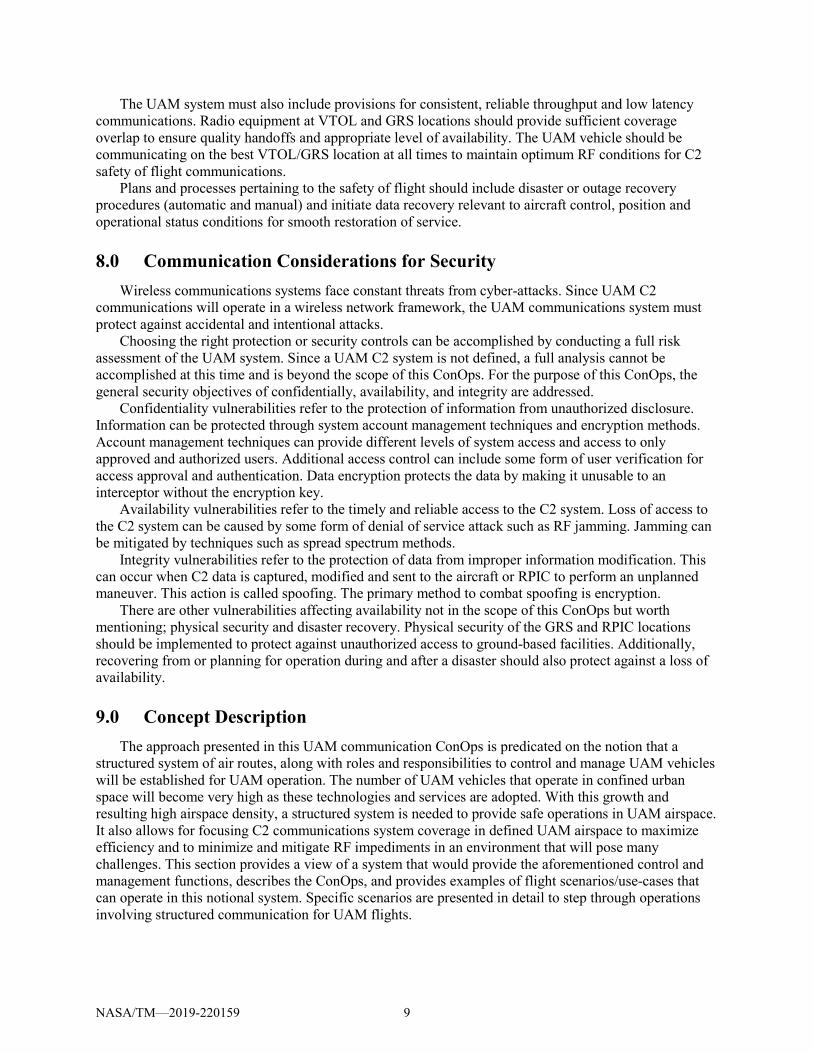
Characteristics • Payload: Passenger. • Vehicle: Hybrid-electric powered, remotely piloted, passenger vehicle with load capacity to safely
accommodate eight passengers. • Communications System Equipage: Onboard C2 radio. • Air Route Operation: VTOL only. Max Altitude (for application) 2500 ft. Nominal route is for within
designated city-center corridor at high altitude boundaries. Routes may include operations in approved UAM Airspace in surrounding suburban areas based on service initiation locations that reside outside of the city-center. These flights provide this service at altitudes that generally fly above urban canyon environment. However, takeoff and landing at VTOL sites may include some urban canyon-like airspaces.
• Vehicle (onboard) Systems: Command and Control (Telecommanding and Telemetry), Intrusion detection, Video system, Surveillance system, Navigation system, Autonomous systems, Vehicle Health monitoring, Onboard Sensors System.
NASA/TM—2019-220159 14

TABLE 2.—OPERATIONAL WALKTHROUGH [Detailed - see Appendix A for Specific Communication Category Data.]
Flight Operation
(Air-Taxi UAM Service)
Note: ‘autoprogram’ used to indicate Autopilot-like system, flight segment, programming.
Commanded by RPIC to Vehicle as needed.
Operation Requiring Comm
Source - Dest
Comm System
Element(s)
Data Type Category
Reference Appendix A, Comm Elements for Category Details
1 2 3 4 5 6 7 8 9 10 11
Com
mands U
L
Telemetry D
L
ATC
Voice/D
ig
Nav A
ids Data D
L
Surv. Data Input
Surv. Data O
ut DL
Weather
Video D
L
Air Traffic Serv
Air O
perations
Vehicle H
ealth DL
1) Beginning at 5:30 am, four ‘Airlift’ personal transport vehicles at the Steelyard Commons (SYC) transport VTOL site are prepped and ready for departure to 4 different downtown, VTOL site passenger drop off locations. Transports leave at staggered 10 min intervals from each of the four AirLift pads.
N/A
2) A RPIC is assigned to the 7:45 am flight N/A
3) Vehicle Prep A – vehicle at Departure VTOL site
- RPIC Comm check – Ground Comm RPIC tests GndNtwk Comm
RPIC -UAM TMS,
AOC, VTOL
GndNtwk ●
- Vehicle prepped on Steelyard Commons VTOL Site Pad 1 VTOL Ops reports status VTOL Ops
- RPIC GndNtwk ●
- Check of mechanical systems AOC Reports Mech Sys Status
AOC - RPIC GndNtwk ●
- RPIC communication check – to vehicle RPIC tests vehicle C2 link RPIC - Vehicle GndNtwk/C2 ● ● ● ● ● ● ●
4) Vehicle Prep B – vehicle at Departure VTOL site - RPIC preps vehicle – preflight tests over C2 system
link. RPIC/Vehicle prep - remote tests
RPIC - Vehicle GndNtwk/C2 ● ● ● ● ● ● ● ●
- RPIC communicates ‘Vehicle Ready’ to VTOL/AOC RPIC Reports ‘Systems Go’
RPIC - VTOL, AOC
GndNtwk ● ●
- RPIC receives 1st route segment, segment Wx data and segment traffic info from AOC.
AOC sends Route / Wx data to RPIC
AOC - RPIC GndNtwk ● ●
- RPIC initiates vehicle telemetry downlink RPIC commands/initiates telemetry DL
RPIC - Vehicle GndNtwk/C2 ● ●
- RPIC configures Vehicle Health system RPIC configures Health Status DL
RPIC - Vehicle GndNtwk/C2 ● ●
- RPIC configures Video system RPIC configures Video system
RPIC - Vehicle GndNtwk/C2 ● ●
NA
SA/TM
—2019-220159
15

Flight Operation
(Air-Taxi UAM Service)
Note: ‘autoprogram’ used to indicate Autopilot-like system, flight segment, programming.
Commanded by RPIC to Vehicle as needed.
Operation Requiring Comm
Source - Dest
Comm System
Element(s)
Data Type Category
Reference Appendix A, Comm Elements for Category Details
1 2 3 4 5 6 7 8 9 10 11
Com
mands U
L
Telemetry D
L
ATC
Voice/D
ig
Nav A
ids Data D
L
Surv. Data Input
Surv. Data O
ut DL
Weather
Video D
L
Air Traffic Serv
Air O
perations
Vehicle H
ealth DL
- VTOL Ops confirms vehicle ‘Ready’ with RPIC. Ready for takeoff
VTOL Ops verifies RPIC Ready status
VTOL Ops - RPIC GndNtwk ● ●
Anita and 7 other Passengers board vehicle N/A
5) Due to proximity to Burke Lakefront Airport and Cleveland Hopkins Intl Airport, the UAM flight will operate in NAS Class B airspace. UAM TMS notifies NAS ATC of the planned air route and flight schedule.
AOC notifies UAM TMS of flight
AOC - UAM TMS GndNtwk ● ●
UAM TMS coordinates route and contingency options w NAS ATC
UAM TMS - NAS ATC GndNtwk ● ●
6) NAS ATC acknowledges the flight plan with UAM TMS. (Note: ATC for this UAM flight will be handled by UAM TMS. Deviations from planned route will be conveyed by the UAM TMS to NAS ATC.)
NAS ATC verifies route with UAM TMS
NAS ATC - UAM TMS GndNtwk ● ●
UAM TMS verifies route with AOC
UAM TMS – AOC GndNtwk ● ●
AOC confirms route and contingency routing to RPIC
AOC - RPIC GndNtwk ● ●
7) Air Taxi is ready for takeoff. RPIC ready for takeoff clearance.
RPIC requests takeoff clearance
RPIC - VTOL Ops GndNtwk ●
VTOL Ops verifies clearance w AOC
VTOL Ops - RPIC GndNtwk ● ●
VTOL Ops sends clearance Msg to RPIC
VTOL Ops - RPIC GndNtwk ● ●
8) VTOL Ops provides takeoff site, 1st segment and Arrival sight Autonomous autoprogram data to RPIC.
VTOL Ops takeoff autoprogram data to RPIC
VTOL Ops - RPIC GndNtwk ●
9) RPIC initiates takeoff autoprogram and vehicle ascends to 2500 ft. altitude directly above VTOL site. Vehicle hovers briefly while RPIC sends enroute 1st segment autoprogram to vehicle. RPIC initiates initial enroute autoprogram. The Entire route will take the vehicle through four designated high altitude city-center corridors: CLEWest-H, CLE South-H, CLE77-H and CLEEuclid-H.
RPIC loads takeoff auto program to vehicle
RPIC - Vehicle GndNtwk/C2 ●
RPIC initiates Surv, NavAids, Video and Vehicle Health systems
RPIC - Vehicle GndNtwk/C2 ● ● ● ● ● ●
RPIC commands takeoff auto program
RPIC - Vehicle GndNtwk/C2 ●
RPIC sends CLEWest segment autoprogram to vehicle.
RPIC - Vehicle GndNtwk/C2 ●
10) Vehicle now operating in CLEWest air corridor heading North - communicated by RPIC to UAM TMS.
RPIC communicates current route in CLEWest
RPIC - UAM TMS GndNtwk ● -- ●
TABLE 2.—Continued. NA
SA/TM
—2019-220159
16

Flight Operation
(Air-Taxi UAM Service)
Note: ‘autoprogram’ used to indicate Autopilot-like system, flight segment, programming.
Commanded by RPIC to Vehicle as needed.
Operation Requiring Comm
Source - Dest
Comm System
Element(s)
Data Type Category
Reference Appendix A, Comm Elements for Category Details
1 2 3 4 5 6 7 8 9 10 11
Com
mands U
L
Telemetry D
L
ATC
Voice/D
ig
Nav A
ids Data D
L
Surv. Data Input
Surv. Data O
ut DL
Weather
Video D
L
Air Traffic Serv
Air O
perations
Vehicle H
ealth DL
11) Vehicle slows as it approaches CLESouth corridor. RPIC checks CLESouth air traffic for corridor clear access and notifies UAM TMS of pending corridor entry.
RPIC notifies UAM TMS of pending CLESouth entry
RPIC - UAM TMS GndNtwk ● ●
UAM TMS confirms CLESouth entry.
UAM TMS - RPIC GndNtwk ●
RPIC initiates CLESouth entry via autoprogram.
RPIC - Vehicle GndNtwk/C2 ●
12) Vehicle transitions into CLESouth segment. RPIC sends autoprogram verification
RPIC - Vehicle GndNtwk/C2 ●
13) Vehicle now operating in CLESouth air corridor heading East - communicated by RPIC to UAM TMS.
RPIC identifies current route in CLESouth
RPIC - UAM TMS GndNtwk ● ●
14) Vehicle slows as it approaches CLE77 corridor. RPIC checks CLE77 air traffic for corridor clear access and notifies UAM TMS of pending corridor entry. Clear access identified.
RPIC notifies UAM TMS of pending CLE77 entry
RPIC - UAM TMS GndNtwk ●
RPIC approves CLE77 entry via autoprogram.
RPIC - Vehicle GndNtwk/C2 ●
15) Vehicle transitions into CLE77 segment. RPIC sends autoprogram entry verification
RPIC - UAM TMS GndNtwk ● ●
16) Vehicle now operating in CLE77 air corridor heading North - communicated by RPIC to UAM TMS.
RPIC communicates current route in CLE77.
RPIC - UAM TMS GndNtwk ●
18) Surveillance system alerts RPIC of moderate traffic in next planned corridor. Vehicle slows as it approaches CLEEuclid corridor. RPIC visualizes CLEEuclid air traffic. RPIC overrides autoprogram to manual control. RPIC commands an airspeed adjustment to accommodate CLEEuclid traffic. RPIC verifies clear access via surv system. RPIC commands vehicle back to autoprogram and notifies UAM TMS of pending entry to CLEEuclid.
RPIC override of autoprogram
RPIC - Vehicle GndNtwk/C2 ●
RPIC manual airspeed adjustment
RPIC - Vehicle GndNtwk/C2 ●
RPIC sets vehicle back to autoprogram
RPIC - Vehicle GndNtwk/C2 ●
RPIC Commands Video On- for visual awareness only.
RPIC - Vehicle GndNtwk/C2 ●
RPIC initiates CLEEuclid entry via autoprogram.
RPIC - Vehicle GndNtwk/C2 ●
19) Vehicle transitions into CLEEuclid segment. RPIC sends autoprogram entry verification
RPIC - UAM TMS GndNtwk ● ●
TABLE 2.—Continued. NA
SA/TM
—2019-220159
17

Flight Operation
(Air-Taxi UAM Service)
Note: ‘autoprogram’ used to indicate Autopilot-like system, flight segment, programming.
Commanded by RPIC to Vehicle as needed.
Operation Requiring Comm
Source - Dest
Comm System
Element(s)
Data Type Category
Reference Appendix A, Comm Elements for Category Details
1 2 3 4 5 6 7 8 9 10 11
Com
mands U
L
Telemetry D
L
ATC
Voice/D
ig
Nav A
ids Data D
L
Surv. Data Input
Surv. Data O
ut DL
Weather
Video D
L
Air Traffic Serv
Air O
perations
Vehicle H
ealth DL
20) Vehicle now operating in CLEEuclid air corridor heading West - communicated by RPIC to UAM TMS.
RPIC communicates current route in CLEEuclid.
RPIC - UAM TMS GndNtwk ● ●
21) Shortly after the vehicle enters CLEEuclid, UAM TMS sends notice for a 3 min hold on arrivals to VTOL Site 3 to all inbound vehicle RPICs. RPIC visually verifies other vehicle activity and drops autoprogram. Manually commands vehicle to hover in place. The RPIC is manually in control of the vehicle.
UAM TMS communicates airspace ‘hold’
UAM TMS - RPIC GndNtwk ●
RPIC acknowledges hold request
RPIC - UAM TMS GndNtwk ●
RPIC overrides CLE Euclid segment autoprogram
RPIC - Vehicle GndNtwk/C2 ●
RPIC commands hover maneuver
RPIC - Vehicle GndNtwk/C2 ●
22) After 1:30 min VTOL Ops lifts the airspace hold, communicates this to UAM TMS who contacts RPICs. RPIC commands the vehicle to complete the remainder of autoprogram route sequence.
VTOL Ops lifts airspace’ hold’
UAM TMS - RPIC GndNtwk ● ●
RPIC confirms ‘hold lifted’ RPIC - UAM TMS GndNtwk ● ●
RPIC reinitiates CLEEuclid autoprogram
RPIC - Vehicle GndNtwk/C2 ●
23) Vehicle operating in CLEEuclid air corridor heading West - communicated by RPIC to UAM TMS.
RPIC communicates current route in CLEEuclid.
RPIC - UAM TMS GndNtwk ● -- ●
24) Vehicle approaches VTOL #3 exit point just east of Playhouse Square where RPIC announces its pending arrival to VTOL Ops and UAM TMS.
RPIC announces arrival to VTOL site
RPIC - VTOL Ops GndNtwk ●
RPIC announces CLEEuclid to VTOL site airspace transition to UAM TMS
RPIC - UAM TMS GndNtwk ●
RPIC Command Video On RPIC - Vehicle GndNtwk/C2 ●
25) Vehicles arrives at VTOL #3. RPIC places vehicle into hover above the site waiting for landing clearance from VTOL Ops.
RPIC commands vehicle to manual
RPIC - Vehicle GndNtwk/C2 ●
RPIC commands vehicle to hover
RPIC - Vehicle GndNtwk/C2 ●
26) VTOL #3 Ops provides updated autoprogram descent information to RPIC who programs the arrival route data to the vehicle. VTOL #3 Ops provide arrival clearance. RPIC initiates autoprogram
VTOL sends new Arrival autoprogram to RPIC
VTOL Ops - RPIC GndNtwk ● ●
RPIC loads new Arrival autoprogram
RPIC - Vehicle GndNtwk/C2 ●
TABLE 2.—Continued. NA
SA/TM
—2019-220159
18

Flight Operation
(Air-Taxi UAM Service)
Note: ‘autoprogram’ used to indicate Autopilot-like system, flight segment, programming.
Commanded by RPIC to Vehicle as needed.
Operation Requiring Comm
Source - Dest
Comm System
Element(s)
Data Type Category
Reference Appendix A, Comm Elements for Category Details
1 2 3 4 5 6 7 8 9 10 11
Com
mands U
L
Telemetry D
L
ATC
Voice/D
ig
Nav A
ids Data D
L
Surv. Data Input
Surv. Data O
ut DL
Weather
Video D
L
Air Traffic Serv
Air O
perations
Vehicle H
ealth DL
27) VTOL Site Ops provides landing clearance. RPIC initiates VTOL site auto-programmed landing after receiving clearance.
VTOL Ops sends landing clearance
VTOL Ops - RPIC GndNtwk
● RPIC commands arrival autoprogram
RPIC - Vehicle GndNtwk/C2 ●
Vehicle lands at VTOL #3 Pad 4. N/A
28) VTOL #3 Ops notifies AOC and UAM TMS of landing. UAM TMS notifies NAS ATC that the vehicle is removed from Class B airspace operation.
VTOL Ops landing notification
VTOL Ops – UAM
TMS and AOC
GndNtwk ●
UAM TMS airspace notification
UAM TMS – NAS ATC
GndNtwk
29) Vehicle Systems secured RPIC commands vehicle shutdown
RPIC - Vehicle GndNtwk/C2 ● -- -- -- -- -- --
Passengers disembark NA After dropping off passengers the vehicle is processed for a safety check. A new fresh vehicle is prepped and put into service. Vehicle Prep A and B is routed to CLE Transport VTOL site #4 with two passengers who missed a previous flight.
NA
- Continuous operation Commanded Activation through Commanded Shut Down
TABLE 2.—Concluded. NA
SA/TM
—2019-220159
19

9.3.2 Use Case 3: Multi-Package Delivery
Synopsis Package delivery service companies use UAM vehicles to distribute products to locations within the
city-center. Each flight carries multiple packages for drop off at multiple VTOL sites. These services are operated from convenient (highway accessible) customer drop-off locations located on the periphery of city-centers. The service flies delivery routes, three flights per day, from each drop-off location to city-center delivery locations located near UAM VTOL sites. Customers pick-up items at the service company storefront located near city-center VTOL sites. Service companies that provide this service provide an operations center with RPIC’s for their vehicles.
Storyline Description John works at an environmental services engineering firm at a location just south of Cleveland, Ohio
at the Parma office (Fig. 7). The big boss in Cincinnati called John and asked him to deliver a new printer to one of their companies’ small site locations across town in Bratenahl, so they are up and running by noon today. John, however, has a very important sales presentation at 1 pm in Broadview Heights that he is still preparing and needs time this morning to complete. John is aware of but has never used AirDel, which is an air service that can quickly airlift packages to multiple sites around greater Cleveland. John checks the air delivery site and schedule of AirDel and finds that if he gets a printer to the nearby AirDel drop point/vertiport at Steelyard Commons by 8:30 am, the printer can be dropped off only a block away from the Bratenahl location for pickup at 10 am. This will save him time to complete his presentation without having to travel back and forth himself during rush hour traffic. John runs to Best Buy at 8 am, drives to the Steelyard Commons location of AirDel by 8:15 am, and is back at his office by 9:00 am. At 10:30 am John receives a message from the Bratenahl location that the printer has arrived and is being set up at Bratenahl. Thanks, John.
Flight Route Diagram
Figure 7.—Multi Point Delivery Service (Map data 2018 Google).
NASA/TM—2019-220159 20
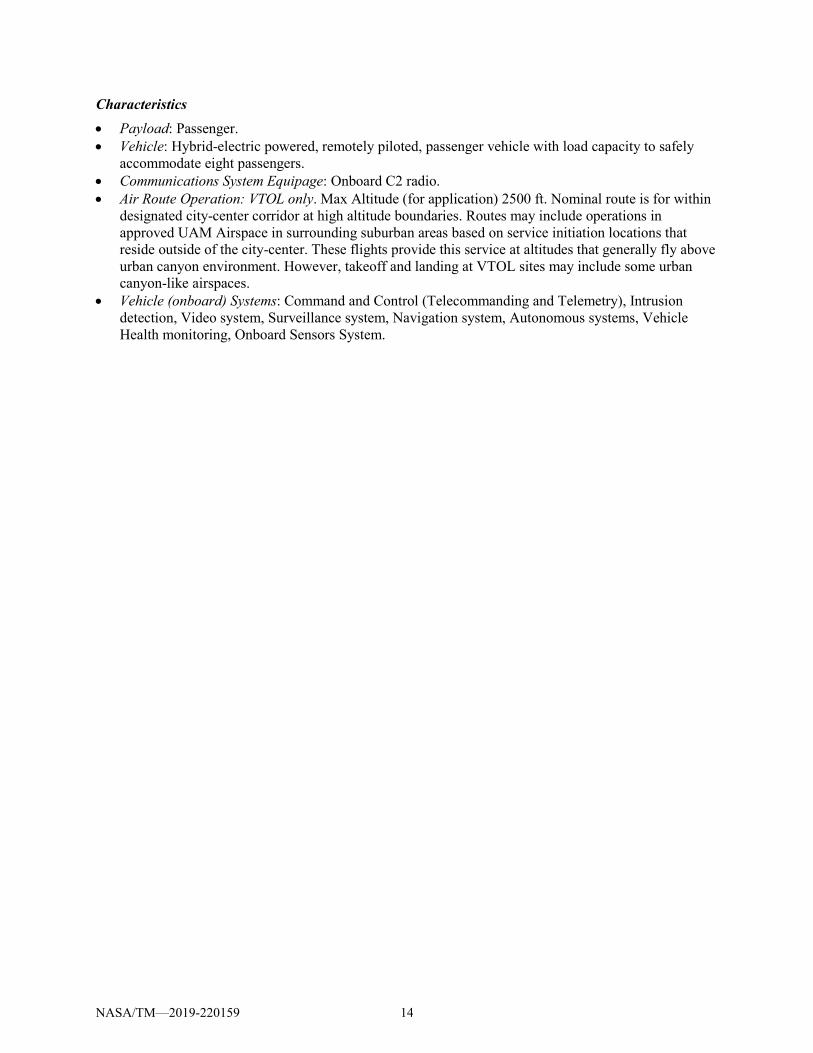
Characteristics • Payload: Cargo. • Vehicle: Hybrid-electric powered, medium size, unmanned drone with max load capacity specified
for package delivery service. • C2 Communication System: Full complement/high-power, onboard C2 radio. • Air Route Operation: VTOL only. Max Altitude (for application) of 1000 ft. Nominal route is for
within designated city-center corridors. These flights provide their services at altitudes that avoid urban canyon environment. However, takeoff and landing at VTOL sites may include some urban canyon airspaces.
• Vehicle (onboard) systems: Command/Control (Telecommanding/Telemetry), Intrusion detection, Video system, Surveillance system, Navigation system, Autonomous systems, Vehicle Health monitoring.
NASA/TM—2019-220159 21

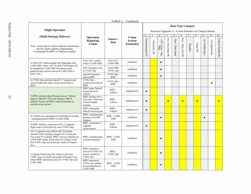
TABLE 3.—OPERATIONAL WALKTHROUGH [Detailed—See Appendix A for specific category data details.]
Flight Operation
(Multi Package Delivery)
Note: ‘autoprogram’ used to indicate Autonomous System, flight segment, programming.
Commanded by RPIC to Vehicle as needed.
Operation Requiring
Comm
Source - Dest
Comm System
Element(s)
Data Type Category
Reference Appendix A—Comm Elements for Category Details 1 2 3 4 5 6 7 8 9 10 11
Telecomm
and UL
Telemetry D
L
ATC
Voice / D
ig M
sg
Nav A
ids Data D
L
Surv. Data Input
Surv. Data O
ut DL
Weather
Video D
L
Air Traffic Serv.
Air O
perations
Vehicle H
ealth DL
1) Package dropped off at SteelYard VTOL Site. Package scheduled for loading onto Air Vehicle. Vehicle loaded with packages for off-load at 6 drop-point/VTOL sites along VTOL Site delivery route.
2) Vehicle Prep A. Delivery vehicle at initial VTOL site
- RPIC Comm check – Ground Comm RPIC Tests Gnd Ntwk Comm
RPIC - ATC, AOC, VTOL GndNtwk ●
- Vehicle loaded on VTOL site launch fixture. VTOL Ops reports status
VTOL Ops - RPIC GndNtwk ●
- Check of mechanical systems AOC Reports Mech Sys Status AOC - RPIC GndNtwk ●
- RPIC communication check – to Vehicle RPIC tests vehicle C2 link
RPIC - Vehicle GndNtwk/C2 ● ● ● ● ● ● ●
3) Vehicle Prep B. Delivery vehicle at initial VTOL site - RPIC preps vehicle – preflight tests over comm
system. RPIC/Vehicle prep - remote tests
RPIC - Vehicle GndNtwk/C2 ● ● ● ● ● ● ● ●
- RPIC communicates ‘Vehicle Ready’ to VTOL/AOC
RPIC Reports ‘Systems Go’
RPIC - VTOL, AOC GndNtwk ●
- RPIC receives 1st route segment, segment Wx data and segment traffic info from AOC.
AOC sends Route / Wx data to RPIC AOC - RPIC GndNtwk ● ●
- RPIC initiates vehicle telemetry downlink RPIC initiates telemetry DL
RPIC - Vehicle GndNtwk/C2 ●
- RPIC configures Vehicle Health system RPIC configures Health Status DL
RPIC - Vehicle GndNtwk/C2 ● ●
- RPIC configures Video system RPIC configures Video system
RPIC - Vehicle GndNtwk/C2 ● ●
- RPIC acknowledges ready status to VTOL Ops. vehicle ready for take-off
RPIC provides ‘Ready’ status to VTOL Ops
RPIC - VTOP Ops GndNtwk ●
4) Due to proximity to Burke Lakefront Airport and Cleveland Hopkins Intl Airport the UAM flight will operate in NAS Class B airspace. UAM TMS confirm the planned air route and flight schedule just prior to initial departure with NAS ATC.
AOC notifies UAM TMS of flight
AOC - UAM TMS GndNtwk ●
UAM TMS coordinates w NAS ATC
UAM TMS - NAS ATC GndNtwk ●
NA
SA/TM
—2019-220159
22
Flight Operation
(Multi Package Delivery)
Note: ‘autoprogram’ used to indicate Autonomous System, flight segment, programming.
Commanded by RPIC to Vehicle as needed.
Operation Requiring
Comm
Source - Dest
Comm System
Element(s)
Data Type Category
Reference Appendix A—Comm Elements for Category Details 1 2 3 4 5 6 7 8 9 10 11
Telecomm
and UL
Telemetry D
L
ATC
Voice / D
ig M
sg
Nav A
ids Data D
L
Surv. Data Input
Surv. Data O
ut DL
Weather
Video D
L
Air Traffic Serv.
Air O
perations
Vehicle H
ealth DL
5) NAS ATC acknowledges the flight plan with UAM TMS. (Note: ATC for this UAM flight will be handled by UAM TMS. Deviations from planned route will be conveyed UAM TMS to NAS ATC.)
NAS ATC verifies route w UAM TMS
NAS ATC UAM TMS GndNtwk ●
ATC Clearance sent to VTOL Ops
UAM TMS VTOL Ops GndNtwk ●
takeoff Clearance sent to RPIC
VTOL Ops - RPIC GndNtwk ●
6) VTOL Ops provides takeoff, 1st segment and Arrival sight auto track, autoprogram data to RPIC.
VTOL Ops – autoprogram data to RPIC
VTOL Ops - RPIC GndNtwk ●
7) RPIC initiates takeoff autoprogram. Vehicle departs Takeoff VTOL site rising to 1000 ft altitude. Pauses for RPIC control transition to enroute autoprogram.
RPIC loads Takeoff autoprogram to vehicle
RPIC - Vehicle GndNtwk/C2 ●
RPIC initiates Surv, NavAids, Video and Vehicle Health systems
RPIC - Vehicle GndNtwk/C2 ● ● ● ● ●
RPIC commands takeoff autoprogram
RPIC - Vehicle GndNtwk/C2 ●
8) Vehicle now operating in CLESouth air corridor - communicated by RPIC to UAM TMS.
RPIC communicates presence in UAM airspace
RPIC - UAM TMS GndNtwk ● ●
9) RPIC initiates autoprogram for 1st segment flight route to first delivery route VTOL Stop.
RPIC commands 1st segment autoprogram
RPIC - Vehicle GndNtwk/C2 ●
10) 1st segment route follows the CLESouth corridor with a heading change to E-N along the way at the I77 corridor. RPIC conveys transition to UAM TMS. Route North takes the vehicle to the first VTOL stop, exit point just south of Prospect Ave.
RPIC communicates corridor transition
RPIC - UAM TMS GndNtwk ●
11) Route North takes the vehicle to the first VTOL stop, exit point just south of Prospect Ave. where RPIC announces arrival to VTOL Ops and UAM TMS.
RPIC announces arrival at VTOL site access corridor to VTOL Ops
RPIC - VTOL Ops GndNtwk ●
RPIC announces VTOL site corridor access transition to UAM TMS
RPIC - UAM TMS GndNtwk ●
TABLE 3.—Continued. NA
SA/TM
—2019-220159
23

Flight Operation
(Multi Package Delivery)
Note: ‘autoprogram’ used to indicate Autonomous System, flight segment, programming.
Commanded by RPIC to Vehicle as needed.
Operation Requiring
Comm
Source - Dest
Comm System
Element(s)
Data Type Category
Reference Appendix A—Comm Elements for Category Details 1 2 3 4 5 6 7 8 9 10 11
Telecomm
and UL
Telemetry D
L
ATC
Voice / D
ig M
sg
Nav A
ids Data D
L
Surv. Data Input
Surv. Data O
ut DL
Weather
Video D
L
Air Traffic Serv.
Air O
perations
Vehicle H
ealth DL
UAM TMS acknowledges trans to UAM airspace.
UAM TMS - RPIC GndNtwk ●
12) VTOL Ops provides updated Arrival landing site autoprogram data to RPIC.
RPIC receives new Arr site landing autoprogram data
VTOL Ops - RPIC GndNtwk ●
RPIC verifies update received
RPIC - VTOL Ops GndNtwk ●
13) Vehicle flies to previously programmed location above VTOL site for landing. RPIC pauses (hovers) vehicle at this location for clearance from VTOL Ops.
RPIC switches to manual control
RPIC - Vehicle GndNtwk/C2 ●
RPIC loads new Arrival autoprogram
RPIC - Vehicle GndNtwk/C2 ●
14) VTOL site Ops provides landing clearance. RPIC initiates VTOL site auto-programmed landing after receiving clearance.
VTOL Ops sends landing clearance
VTOL Ops - RPIC GndNtwk ●
RPIC initiates Arrival autoprogram
RPIC - Vehicle GndNtwk/C2 ●
Vehicle lands at first delivery Vertiport.
15) VTOL Ops notifies UAM TMS of landing and UAM TMS notifies NAS ATC that the vehicle is removed from Class B airspace operation.
VTOL Ops landing notification
VTOL Ops - UAM TMS GndNtwk ●
UAM TMS airspace notification
UAM TMS - NAS ATC GndNtwk ●
16) Vehicle Systems secured RPIC commands vehicle/systems shutdown
RPIC - Vehicle GndNtwk/C2 ● -- -- -- -- --
17) Vehicle ground-processed for drop off of packages delivered to this VTOL location. N/A
TABLE 3.—Continued. NA
SA/TM
—2019-220159
24

Flight Operation
(Multi Package Delivery)
Note: ‘autoprogram’ used to indicate Autonomous System, flight segment, programming.
Commanded by RPIC to Vehicle as needed.
Operation Requiring
Comm
Source - Dest
Comm System
Element(s)
Data Type Category
Reference Appendix A—Comm Elements for Category Details 1 2 3 4 5 6 7 8 9 10 11
Telecomm
and UL
Telemetry D
L
ATC
Voice / D
ig M
sg
Nav A
ids Data D
L
Surv. Data Input
Surv. Data O
ut DL
Weather
Video D
L
Air Traffic Serv.
Air O
perations
Vehicle H
ealth DL
18) Vehicle continues route to next delivery service VTOL site – repeats operations starting at Vehicle Prep B (above) for each segment of the total delivery service route. John’s package is dropped off at the third stop at the Rockefeller Park VTOL site, the delivery vehicle continues to all delivery sites.
19) On its return to the original Steelyard Commons site a package that was loaded for delivery to Steelyard Commons at the Edgewater Park VTOL site is off-loaded. The vehicle is then returned to the service pool of aircraft for maintenance inspections
- Continuous operation Commanded Activation through Commanded Shut Down
TABLE 3.—Concluded. NA
SA/TM
—2019-220159
25

10.0 Summary The UAM concept is a new and untested mode of air transportation. It will require new regulations
for the vehicles, pilots, controllers, and related communications systems. It will also require dedicated RF spectrum along with the associated performance specifications to avoid interference and other signal degradations. This UAM C2 ConOps makes assumptions, based on extensive experience with C2 aeronautical communications for UAS, in order to anticipate the requirements for safe UAM operations.
In today’s NAS, aeronautical operations are supported by communications systems that are fully developed and well understood (i.e., equipage, regulations, and procedures). In the future UAM environment addressed in this ConOps, wherein the pilot is remotely connected to the vehicle, a new and substantially different communications system will be required to enable remote command and control of the aircraft in a dense, complex urban airspace.
The NAS RF communications environment is straightforward compared to the UAM environment. A congested urban area presents RF issues not generally encountered in the open spaces of the NAS. Operating in the much smaller volumes of space in a city-center increases both situational awareness and safety concerns.
This ConOps discusses the C2 data that will be needed, identifies the source and destination of that data, and fully illustrates the command and control aspects of several envisioned use cases. The ConOps also suggests a notional communications infrastructure that will support C2.
However, the ConOps does not specify any specific technical solutions. Once the concept is fully developed, it will require a detailed technical assessment. The technical assessment will consider existing technologies that can fully or partially meet UAM C2 communications requirements. Any remaining concerns will be identified as technology gaps and will be dealt with in a gap analysis.
UAM will require new communications and air traffic management approaches. This ConOps establishes the framework for the C2 development that needs to occur. The studies that will follow will provide the details needed to actualize these concepts.
NASA/TM—2019-220159 26

Appendix A.—Communication Elements Breakdown Table Table 4 contains groupings of current and legacy aviation systems, along with operational services for
aircraft and presumed for UAM vehicles. These systems/services are assembled here as candidates for UAM operations within the scope of this ConOps. Listed are the data and information types that may need to be carried over the C2 communications link. Use of each system is not expected for all UAM vehicles, but rather their specific utilization is expected to be based on the UAM vehicle implementation in the environment or the UAM vehicle class and complexity for operation in this system.
Each general data category (1 through 11) is defined and then expanded into specific items. For each detail line item service, a source and destination element are presumed based on an unmanned vehicle, RPIC UAM operating scenario. Columns to the right provide; (1) a designation as to whether the data type is expected to be carried over the C2 link, (2) whether the data is defined/designated within the DO-362 specification, (3) whether the data is uniquely tied to AOC activities, and (4) whether it can be ruled out completely for being carried over the C2 Communication link.
NASA/TM—2019-220159 27

TABLE 4.—C2 DATA CATEGORIES Data Category and System Source Destination Carried
over UAM C2 uplink or downlink
DO-362 (C2 Elements)
UAM Specific C2
AOC, etc. Definitely not C2
1 Telecommands (Uplink) Uplinked commands carried over the C2 link to the UAM vehicle that direct the flight or direct operation of an onboard system. Commands are sent for immediate contact with each subsystem
to alter an existing state or to reconfigure the system for future operation. 1a Aircraft Control commands RPIC UA X X X
1b Navigation System commands RPIC UA X X X
1c Surveillance Systems commands RPIC UA X X X
1d Weather/Video Systems commands RPIC UA X X X
1e Detect-and Avoid System commands GBDAA UA, RPIC X X X
1f Autonomous System commands RPIC UA X X X
2 Telemetry (Downlink) Downlinked data carried over the C2 link from the aircraft and onboard vehicle systems. Telemetry would include vehicle state/status information and onboard system information that is
deemed critical for command response acknowledgment and vehicle system status. Data may be delivered directly to appropriate destinations or sent via ground systems for processing and monitoring by ground-based systems.
2a Vehicle data (Aircraft subsystems data, sensor data) UA RPIC X X X
2b Aircraft State data (Lat/Lon, Alt, heading, Airspeed, etc…)
UA RPIC, AOC, ATM X X X
2c Aircraft command-response data UA RPIC X X X
2d Surveillance system status UA RPIC X X X
2e Navaids system status UA RPIC X X X
2f DAA ops/system status UA RPIC X X X
2g Autonomous system Ops/status data UA RPIC X X X
3 Voice/Data Air Traffic Control voice or data messages for managing the vehicles airborne/airspace operations. Information is exchanged between traffic controllers and Pilots or Pilots-in-Control to
provide traffic flow control, situation awareness, emergency information and re-routing information as needed. 3a ATC VHF/voice to RPIC (also provides SA to piloted
aircraft) ATC RPIC X X X
3b RPIC VHF/voice to ATC (also provides SA to piloted aircraft)
RPIC ATC X X X
3c DataComm to RPIC ATC, AOC, VTOL RPIC X X X 3d RPIC DataComm to ATC/AOC/VTOL RPIC ATC, AOC, VTOL X X X 4 Navigational Aids Data Operational data from onboard or ground-based navigation systems that need to be accessed by the vehicle downlinked to ground systems or uplinked from ground systems to the aircraft for
accurately ascertaining its position and planning and following a route. 4a ILS ILS, UA UA, RPIC ** X
4b VOR VOR, UA UA, RPIC ** X
4c NDB NDB, UA UA, RPIC ** X
4d DME DME, UA UA, RPIC ** X
4e GPS/WAAS/GBAS G/W/G, UA UA, RPIC ** X
4f Markers Markers, UA UA, RPIC X
5 Surveillance Data Input Operational data uplinked to the vehicle from legacy NAS and/or UA specific surveillance systems that support the observation of the vehicle for airspace supervision.
5a ADSB In Other AC UA, RPIC ** X
5b TIS TIS UA, RPIC ** X
5c Onboard Surveillance Radar Onboard Surveillance Radar
UA, RPIC ** X
NA
SA/TM
—2019-220159
28

TABLE 4.—Concluded. 5d GBDAA GBDAA UA, RPIC X X X
5e TCAS Other AC UA, RPIC ** X
5f Onboard DAA Onboard DAA, Other AC
UA, RPIC X X X
6 Surveillance Data Output Operational data transferred from the vehicle from legacy NAS and/or UA specific systems for observation of the vehicle location for airspace supervision.
6a ADSB Out UA Other AC **
X 6b Radar (SSR) UA ATM **
X
6c Onboard DAA UA Other AC, ATM X
X 6d TCAS UA Other AC **
X
7 Weather Information Data collected onboard the vehicle and requiring downlink, or collected and processed from ground systems requiring uplink that is related to the state of the atmosphere where the vehicle
currently resides or will enter as part of its flight route. 7a Weather info from onboard sensors/TAMDAR UA RPIC, ATM X X 7b Onboard Wx Radar data UA RPIC, ATM X *** X 7c Ground-based weather sources AOC, Other RPIC X 7d VTOL site weather system data VTOL site UA, RPIC X 8 Video Motion/visual image data transferred from the vehicle to the ground pilot and to ground systems for airspace/aircraft status.
8a Pilot-view HD video (multidirectional?) UA RPIC X *** X X 8b Vehicle Payload/Passenger area video UA RPIC, AOC X *** X 9 Air Traffic Services Data from services that assist pilots, vehicle systems and traffic/flight operations with vehicle route management.
9a Traditional ATS (TFR, SUA, etc.) ATM RPIC X 9b NOTAMs (per DO-362) ATM RPIC, UA X 10 Air Operations Data that is transmitted to a vehicle or collected from a vehicle that is specific to vehicle owner/fleet management.
10a Dispatch, scheduling AOC VTOL site, RPIC
X
10b VTOL site status/restrictions VTOL Site AOC, RPIC, UA X
10c Route Information, Region Wx Forecast Data, Autonomous Systems program data
AOC RPIC X X
10d VTOL Site Departure/Arrival Autonomous TO/Landing data
VTOL site RPIC X
X
11 Vehicle Health (Downlink) Data transmitted to ground systems to report vehicle physical state.
11a Vehicle Health Data UA RPIC, AOC, Manufacturer,
Prognostic Service
X X X
11b Vehicle Health Data AOC, Manufacturer,
Prognostic Service
RPIC, AOC X X
* Currently undefined UAM ATS ** UAM vehicles would need to be equipped with these non-C2 systems to operate safely outside of the UAM designated airspace. *** Bandwidth/link capacity would need to be available
NA
SA/TM
—2019-220159
29


Appendix B.—Use-Case Scenarios (Addendum to Section 9.3)
B.1 Use Case 2: Metro Air Shuttle Service
Synopsis This scenario uses large electric VTOL vehicles capable of carrying up to eight passengers to fly
routinely scheduled routes between VTOL sites (i.e., UAM “Bus” stops) within a city-center. Primarily employed in larger sprawl city-centers, this service provides a scheduled service from designated locations around the city for people needing to commute across city-centers for personal and business use where driving/parking is inconvenient. The service might be an extension of a cab company or city-owned transportation service. A metro air shuttle is operated by a qualified UAM company who provide the AOC/RPIC’s for the shuttle service fleet. Vehicles for this application would be larger class UAM vehicles capable of carrying up to eight passengers and would fly at an altitude of 1500 ft.
Storyline Description San Francisco is a large metropolitan city that covers an area of about 46.89 square miles, with a 2017
census-estimated population of 884,363 making its city-county area the fifth most densely populated U.S. County. Although San Fran has an excellent reputation for public commuter services for travel around the city, it has added public Metro Air Shuttle Service to its mix of commuter options. The service is set up to provide a means to limit the duration and complication of cross-town transit available via trains and busses and assumes that users of the service are willing to pay the price for the convenience as the need arises. The service provides two routes for the air shuttle (Fig. 8), each route having several air-stop locations along the route that are situated for convenience to most traveled areas of the city for both tourist and business destinations. Users of the service find a regular schedule of vehicles that make stops during a 15-hour day beginning at 5 am and running through 8 pm. Commuters who use the service pay for the route they plan to use at a street level kiosk that schedules them, and then proceed to the VTOL site entrance for their ride.
Flight Route Diagram
Figure 8.—San-Fran Air Shuttle Service (Map data 2018 Google).
NASA/TM—2019-220159 31

Characteristics • Payload: Passenger. • Vehicle: Hybrid-electric, VTOL aircraft with eight-passenger seating capacity and safe weight
loading capacity. • C2 Communications System: Full complement, onboard C2 radio. • Air Route Operation: VTOL only. Max Altitude (for enroute ops) 2500 ft. Nominal route is within
designated city-center corridor at high altitude boundaries and will avoid urban canyon environment.* • Vehicle (onboard) Systems: Command/Control (Telecommanding/Telemetry), Intrusion detection,
Video system, Surveillance system, Navigation system, Autonomous systems, Vehicle Health monitoring, Onboard Sensors System.
*Note: Takeoff and landing at city-center VTOL sites may include urban canyon-like airspace.
Operational Walkthrough (General) 1. An Air-stop UAM service vehicle begins with processing at one of two Service VTOL sites before
being put into service. Up to three vehicles are processed for routes separated in 15 min intervals depending on the number of scheduled users. Vehicles are swapped out of service after each 4-hour tour in the route. The UAM AOC tracks schedule of usage and notifies the San Fran South Service VTOL facility that the first route of the day begins at 5:15 am. AOC schedules the RPIC for the flight at 4:30 am.
2. AOC contacts UAM TMS to identify the first service flight of the day. 3. The piloting service that operates the vehicles assigns a RPIC for the flight and the RPIC begins a
dialog with UAM TMS and the local VTOL Ops to coordinate the flight. 4. At the Service VTOL, the vehicle is readied for initial checkout. 5. Vehicle Prep A: Vehicle loaded onto VTOL launch fixture Check of mechanical systems and check
of communications is completed with contact between, Service VTOL Ops - RPIC, RPIC - vehicle, and AOC - RPIC.
6. Vehicle Prep B: At 5 am the RPIC remotely preps vehicle by exercising preflight vehicle tests. RPIC receives vehicle route information, Weather (Wx) data, and route traffic info from AOC. RPIC communicates vehicle test data ‘positive’ to Service VTOL, Service VTOL Ops confirms ‘ready’ - verifies with RPIC ready for take-off.
7. The initial leg of the flight will take the vehicle from the Service VTOL into the Market St. Air corridor, into the 10th St. Air corridor where its first arrival will be at VTOL Site #1.
8. Service VTOL Site coordinates ‘ready for departure’ with UAM TMS. Service VTOL site provides TO autoprogram to RPIC.
9. RPIC Initiates Video, Vehicle Health system and Surveillance system data downlink. RPIC transfers TO autoprogram data to the vehicle.
10. Service VTOL site verifies with UAM TMS ‘clear departure and route schedule.’ 11. RPIC initiates TO autoprogram. Vehicle departs Service VTOL site rising to 1500 ft. Pauses for
RPIC control transition. Vehicle entry into Market St. air corridor - communicated by RPIC to UAM TMS. Vehicle is in RPIC control.
12. RPIC initiates autoprogram for flight route Market St. air corridor to 10th St corridor to VTOL #1 arrival point.
13. RPIC announces arrival at VTOL Site #1 to VTOL #1 Ops. Places the vehicle in hover mode over VTOL #1 landing area. VTOL #1 Ops provides arrival autoprogram.
14. RPIC loads VTOL #1 site arrival autoprogram. RPIC receives clear for landing from VTOL #1 Ops. RPIC initiates autoprogram landing. Vehicle arrives at first VTOL for first passengers pick up. Passenger loading available.
NASA/TM—2019-220159 32

15. During this first stop, it is required for the VTOL site and the RPIC to run through a sequence of vehicle and communications tests prior to being cleared for departure. Batteries are tested for charge level.
16. Test complete—VTOL Ops and RPIC coordinate ‘ready for departure.’ VTOL communicates with UAM TMS for clearance.
17. VTOL provides RPIC with takeoff autoprogram. RPIC verifies all systems initiated by sending a request to the vehicle. RPIC loads takeoff autoprogram.
18. UAM TMS provides clearance. 19. RPIC initiates takeoff autoprogram stopping the vehicle briefly directly above VTOL #1. 20. RPIC loads the standard route autoprogram for its next leg of the route, which will take it back into
the 10th St corridor. 21. RPIC approaches the King St air corridor and communicates its planned entry with UAM TMS. The
vehicle enters into the King St corridor where it will stop for pickup of two passengers at the VTOL Site #2 location.
22. For each stop along its route the UAM vehicle and local VTOL Ops site coordinate the landing, passenger pick up, vehicle testing and departure process.
23. After three and a half hours of servicing the San Fran South route with 15 stops during this tour, the vehicle exits the route and returns the vehicle to the Service VTOL site.
24. RPIC commands Vehicle Health and route State data download/storage at Service VTOL Site. 25. RPIC shuts down vehicle. Vehicle secured. 26. On its return to the Market St. Service VTOL site, the vehicle is returned to the service pool of
aircraft for diagnostics and maintenance inspections.
B.2. Use Case 4: Point-To-Point Package Delivery
Synopsis On-demand delivery service for packages from one city-center location to another. UAM companies
operate the service with customer drop-off, customer pick-up locations near VTOL sites distributed within the city-center. Vehicles fly from VTOL site to VTOL site distributing the packages for end-user/customer retrieval at a receiving location. For operations of this scenario/service, each Service Company, or groups of companies that provide related service, provide an operations center (AOC) with assigned ground pilots of medium size, drone vehicles capable of carrying a limited size/weight package depending on the vehicle.
Storyline Description A NYC architectural firm (ArchInc) has just completed the set of drawings for a project proposal that
needs to be delivered to, and processed by, a title company prior to incorporating them into their final data package and submitting it to the city. The architectural firm resides at the corner of 34th St and 7th Ave and needs to deliver the drawings quickly to the title company located near NYC City Hall (at Church and Chambers Ave) (Fig. 9).* ArchInc has used the ‘AirDrop’ package delivery service in many situations to deliver/receive all types of packages, and a decision is made that the timeliness of this shipment is best handled by AirDrop who has a pick-up/drop location nearby their office and just down the block from the title service. The package is hand carried to the 34th and 7th AirDrop location for delivery at 9:30 am and ArchInc receives a call at 10:15 am verifying its arrival at the title company.
*Note: As part of regulations adjustments for UAM operations, Hudson River Special ATC rules will be
followed.
NASA/TM—2019-220159 33

Flight Route Diagram
Figure 9.—Point-to-Point Package Delivery (Map data 2018 Google).
Characteristics
• Payload: Cargo. • Vehicle: Electric powered, medium-small unmanned vehicle with appropriately sized max load
capacity. • C2 Communications System: Low size, weight, and power (SWaP) Onboard C2 radio. • Air Route Operation: VTOL only. Max Altitude (for application) of 500 ft. Nominal route is for
within designated city-center corridors, which includes flying in urban canyon environment. • Vehicle (onboard) systems: Command/Control, Intrusion detection, Pilot-view Video system,
Surveillance system, Autonomous systems, Vehicle Health monitoring.
NASA/TM—2019-220159 34

B.3 Use Case 5: Life Flight Support
Synopsis Medical facilities provide as-needed, ad-hoc flights of UAM vehicles for quick dispatch of life flight
medical equipment. Operators for these flights are contracted UAM delivery service operators qualified to fly these as-needed, specialty UAM routes from the hospital to ‘in-field’ Life Flight teams. In this scenario, Life Flight teams identify needed equipment based on an assessment of the situation at a field location of an emergency situation they are actively working. Air routes for these flights would take the vehicle from a city-center VTOL site near (or even at) the hospital to any location within range of the UAM vehicle. These flights would fly as priority UAM service that crosses between UAM corridors to expedite providing their payload to a life flight team. Contracted service companies would provide an operations center with RPICs for these vehicles.
Storyline Description A serious auto accident involving a van with several workers/passengers occurs on Interstate 90 at
Deadman’s curve near downtown Cleveland. The van has been sideswiped by a truck changing lanes just entering the turn. Multiple severely injured occupants are reported to need immediate medical assistance. The first police cruiser on the scene contacts Medical Health (MH) Life Flight (Fig. 10), which arrives at the scene to find four persons that will need life flight transport. The Life Flight medical staff recognize that their equipment does not include enough specialized head and back trauma equipment that will be needed, so the team requests that a vehicle be dispatched to deliver two sets of this equipment ASAP. Since the hospital has medium class drone delivery vehicles for dispatch from the MH VTOL site, a medium class drone is made available, loaded with the needed equipment and prepared for quick dispatch to deliver to the accident site.
Flight Route Diagram
Figure 10.—Medical Life-Flight Support (Map data 2018 Google).
NASA/TM—2019-220159 35
Characteristics • Payload: Cargo. • Vehicle: Medium size, hybrid-electric, UAM drone with appropriate load capacity. Equipped with
stowage area sized for transporting a wide range of medical support type equipment. • C2 Communications System: Low SWaP Onboard C2 radio. • Air Route Operations: VTOL only. Up to 1000 ft altitude. Operate within designated city-center
corridors with ‘priority’ flight status due to emergency operation being performed. Air route deviates from corridors to accommodate location of the emergency situation. May fly in NAS classified airspace requiring ATC.
• Vehicle (onboard) systems: Command/Control, Intrusion detection, Pilot-view Video system, Surveillance system, Autonomous systems, Vehicle Health monitoring.
Operational Walkthrough 1. MH AOC contacts UAM TMS to identify the emergency drone flight. The flight and route are
quickly provided authorization and priority status in the UAM city-center airspace. 2. The piloting service that operates the vehicles out of MH assigns a RPIC for the flight and the RPIC
begins dialog with UAM TMS and the MH VTOL Ops to coordinate the flight.* *Note: Due to the urgency of the situation the route is a nonstandard route where the vehicle will fly in available low altitude UAM corridors, but also fly across other UAM corridors and be given special traffic priority clearance. UAM TMS provides this information to all other UAM AOC services, and a schedule and map of the route is provided to the RPIC and for distribution to all AOC centers for distribution to all RPICs of active vehicles.
3. With the route identified for a crossover between the CLE West corridor and the CLE Euclid corridor, UAM TMS uses data obtained from the UAM Air Traffic Analysis Center to predict this flight’s time-of-entry into the CLE Euclid Center. UAM TMS notifies the AOC’s for all UAM vehicles flying in CLE Euclid at that time that this flight will be entering and that there will be a hold-in-place order sent to all vehicles operating in CLE Euclid with advance notice of the approximate time. The hold in place announcement will also be transmitted to all VTOL sites servicing CLE Euclid so that they can hold new entries into CLE Euclid for that timeframe.
4. Vehicle Prep A: Vehicle loaded onto VTOL launch fixture, check of mechanical systems, check communications.
5. Vehicle Prep B: RPIC remotely preps vehicle by exercising preflight vehicle tests. RPIC receives vehicle route information, Wx data, and route traffic info from AOC. RPIC communicates vehicle test data ‘positive’ to VTOL, VTOL ops confirms ‘ready’ – verifies with RPIC ready for take-off.
6. The vehicle is loaded with the needed equipment. 7. The final route data is provided to the RPIC by the MH AOC. 8. VTOL site provides takeoff autoprogram to RPIC. RPIC transfers takeoff autoprogram data to vehicle. 9. RPIC commands onboard Video system, Vehicle Health System and Surveillance system to active.
Video system will be used for non-standard landing site operations. 10. MH VTOL site verifies with UAM TMS ‘clear departure and route schedule.’ 11. UAM TMS approves takeoff clearance. MH VTOL site provides takeoff ‘clearance’ to RPIC. 12. RPIC initiates takeoff autoprogram. Vehicle departs takeoff VTOL site rising to 1000 ft altitude.
Pauses for RPIC control transition. Vehicle entry into CLE West mid-altitude air corridor - communicated by RPIC to UAM TMS. Vehicle is in RPIC control.
13. RPIC initiates autoprogram for flight route through initial CLE West air corridor. 14. Due to the nonstandard route, RPIC drops autoprogram to manually fly the vehicle as it exits the CLE
West air corridor.
NASA/TM—2019-220159 36

15. UAM TMS advises vehicle AOCs operating in CLE Euclid of temp hold for 10 min to allow vehicle to pass through CLE Euclid segment for emergency ops.
16. Vehicle exits CLE Euclid and RPIC actively flies the remainder of the flight to the accident site. 17. At the site vehicle maintains 1000 ft altitude. 18. RPIC manages the flight to a hover mode over the accident site. RPIC communicates its hover and
intent to land the vehicle through contact with UAM TMS and its AOC who communicate with the ground Life Flight team. RPIC then initiates an autoprogrammed decent to a visually selected open area near the accident site. Lands the vehicle.
19. Med equipment unloaded 7 min after Life Flight request. 20. Since the return trip is not emergency critical, the RPIC coordinates a more standard return route with
UAM TMS that will follow standard nearby air corridors. 21. RPIC requests autoprogram route from the current location. RPIC sends takeoff autoprogram to drone. 22. RPIC requests takeoff clearance from UAM TMS. UAM TMS sends clearance along with route Wx data. 23. RPIC initiates vertical takeoff via autoprogram. Drone pauses at 1000 ft and RPIC sends route
autoprogram to vehicle. RPIC initiates route autoprogram. 24. Vehicle flies auto route back to MH VTOL site. Pauses over site for landing autoprogram. RPIC
receives MH VTOL site landing clearance and initiates vertical decent autoprogram. 25. Vehicle lands at MH VTOL pad. 26. RPIC initiates shutdown of the vehicle. Vehicle secured.
B.4. Use Case 6: Surveillance Services
Synopsis Using medium-size air drones, customers dispatch these UAM vehicles for 1 to 3 hr duration flights,
flying hover, repeated or gridded, air-routes over city-centers. The flights are used for a variety of reasons including visual monitoring of specific sites, collecting of air quality data or traffic monitoring, etc. around the city-center. Objectives for these flights might be video surveillance with video transmitted live via customer system to the ground or data capture where airborne information is collected for analysis after the flight ends. Flights will occur at altitudes that would not interfere with other UAM operations or air traffic and are not operated solely in UAM corridors. Routes would initiate at a single city-center VTOL location, and return to that location when their service is completed. The scenario could occur on a daily basis and possibly for multiple flights per day. The customers for this service would contract a UAM service company and equip the vehicles with unique equipment as necessary, or if adequate, use systems provided inherently on board the vehicle (e.g., High Definition video downlink, environmental sensors).
Storyline Description A Cleveland based research firm has a city government contract to provide information related to the
traffic patterns in and around the baseball/basketball sports complexes in Cleveland, Ohio (Fig. 11). The study will help identify the addition of new roadways to connect downtown with the busiest roads in and around the complex to help create better traffic flow for the next 20 years.
For the investigation, the research firm contracts a video service that makes applications with video equipment for this purpose and have software that can do analysis of traffic, real-time, to allow the camera to focus on situational segments of an observation window. The system will save video, download video via their own downlink and save analyzed situational data from a flight. The city contracts with this company who uses an unmanned air vehicle company for a series of flights intended to adequately cover seasonal movement of traffic in this area. The air route selected is repetitive for ten loops of the same route flying at up to 750 ft altitude, but outside of any common UAM service airspace as much as possible. Each flight will initiate at the Euclid St. VTOL site which is a common site for other UAM air traffic.
NASA/TM—2019-220159 37
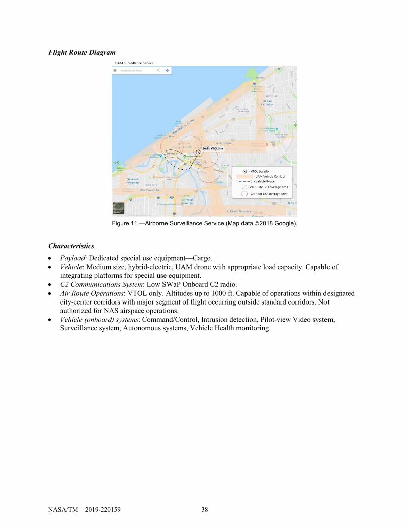
Flight Route Diagram
Figure 11.—Airborne Surveillance Service (Map data 2018 Google).
Characteristics • Payload: Dedicated special use equipment—Cargo. • Vehicle: Medium size, hybrid-electric, UAM drone with appropriate load capacity. Capable of
integrating platforms for special use equipment. • C2 Communications System: Low SWaP Onboard C2 radio. • Air Route Operations: VTOL only. Altitudes up to 1000 ft. Capable of operations within designated
city-center corridors with major segment of flight occurring outside standard corridors. Not authorized for NAS airspace operations.
• Vehicle (onboard) systems: Command/Control, Intrusion detection, Pilot-view Video system, Surveillance system, Autonomous systems, Vehicle Health monitoring.
NASA/TM—2019-220159 38

Appendix C.—Abbreviations and Acronyms
ADS-B Automatic Dependent Surveillance-Broadcast AOC Airline Operational Control Center ATC Air Traffic Control ATM Air Traffic Management ATS Air Traffic Services Comm Communication(s) C2 Command and Control ConOps Concept of Operations DAA Detect and Avoid DL Down Load DME Distance Measuring Equipment FAA Federal Aviation Administration FCC Federal Communications Commission GBAS Ground-Based Augmentation System GBDAA Ground-Based Detect and Avoid GndNtwk/C2 Ground Network/Command and Control GRC Glenn Research Center GRS Ground Radio Station GPS Global Positioning System ILS Instrument Landing System NAS National Airspace System NDB Non-Directional Beacon NOTAM Notice to Airman OPS Operations RF Radio Frequency RPIC Remote Pilot in Command TAMDAR Tropospheric Airborne Meteorological Data Reporting TCAS Traffic Alert and Collision Avoidance System TIS Traffic Information Service TMS Traffic Management System TO Takeoff UAM Urban Air Mobility UAS Unmanned Aircraft System UL Up Load VHF Very High Frequency VOR Very High-Frequency Omnidirectional Range VTOL Vertical Take Off and Landing WAAS Wide Area Augmentation System Wx Weather
NASA/TM—2019-220159 39


