concepts and applications of aerodynamic attitude and
TRANSCRIPT
The University of Manchester Research
Concepts and Applications of Aerodynamic Attitude andOrbital Control for Spacecraft in Very Low Earth Orbit
Document VersionAccepted author manuscript
Link to publication record in Manchester Research Explorer
Citation for published version (APA):Livadiotti, S., Crisp, N., Roberts, P., Edmondson, S., Haigh, S., Huyton, C., Lyons, R., Abrao Oiko, V. T., Smith, K.,Sinpetru, L., Straker, A., Worrall, S., & et al. (2019). Concepts and Applications of Aerodynamic Attitude andOrbital Control for Spacecraft in Very Low Earth Orbit. In 70th International Astronautical Congress (IAC)https://iafastro.directory/iac/archive/browse/IAC-19/Published in:70th International Astronautical Congress (IAC)
Citing this paperPlease note that where the full-text provided on Manchester Research Explorer is the Author Accepted Manuscriptor Proof version this may differ from the final Published version. If citing, it is advised that you check and use thepublisher's definitive version.
General rightsCopyright and moral rights for the publications made accessible in the Research Explorer are retained by theauthors and/or other copyright owners and it is a condition of accessing publications that users recognise andabide by the legal requirements associated with these rights.
Takedown policyIf you believe that this document breaches copyright please refer to the University of Manchester’s TakedownProcedures [http://man.ac.uk/04Y6Bo] or contact [email protected] providingrelevant details, so we can investigate your claim.
Download date:13. Jul. 2021

70th International Astronautical Congress (IAC), Washington D.C., United States, 21-25 October 2019.
Copyright 2019 by The University of Manchester. Published by the IAF, with permission and released to the IAF to publish in all forms.
IAC-19-C1,1,3,x50777 Page 1 of 14
IAC-19,C1,1,3,x50777
Concepts and Applications of Aerodynamic Attitude and Orbital Control for Spacecraft in Very Low
Earth Orbit
Sabrina Livadiottia*, Nicholas H. Crispb, Peter C.E. Robertsa, Steve Edmondsona, Sarah J. Haigha, Claire
Huytona, Rachel E. Lyonsa, Vitor T.A. Oikoa, Katharine L. Smitha, Luciana A. Sinpetrua, Alastair Strakera,
Stephen D. Worrala, Jonathan Becedasb, Rosa María Domínguezb, David Gonzálezb, Valentín Cañasb,
Virginia Hanessianc, Anders Mølgaardc, Jens Nielsenc, Morten Bisgaardc, Adam Boxbergerd, Yung-An
Chand Georg H. Herdrichd, Francesco Romanod, Stefanos Fasoulasd, Constantin Traubd, Daniel Garcia-
Almiñanae, Silvia Rodriguez-Donairee, Miquel Sureda e, Dhiren Katariaf, Ron Outlawg,
Badia Belkouchih, Alexis Conteh, Jose Santiago Perezh, Rachel Villainh, Barbara Heißereri and Ameli
Schwalberi
a The University of Manchester, Oxford Road, Manchester, M13 9PL, United Kingdom b Elecnor Deimos Satellite Systems, Calle Francia 9, 13500 Puertollano, Spain c GomSpace AS, Langagervej 6, 9220 Aalborg East, Denmark d University of Stuttgart, Pfaffenwaldring 29, 70569 Stuttgart, Germany e UPC-BarcelonaTECH, Carrer de Colom 11, 08222 Terrassa, Barcelona, Spain f Mullard Space Science Laboratory (UCL), Holmbury St. Mary, Dorking, RH5 6NT, United Kingdom g Christopher Newport University Engineering, Newport News, Virginia 23606, United States h Euroconsult, 86 Boulevard de Sébastopol, 75003 Paris, France i concentris research management gmbh, Ludwigstraße 4, D-82256 Fürstenfeldbruck, Germany
* Corresponding Author: [email protected]
Abstract
Spacecraft operations below 450km, namely Very Low Earth Orbit (VLEO), can offer significant advantages over
traditional low Earth orbits, for example enhanced ground resolution for Earth observation, improved communications
latency and link budget, or improved signal-to-noise ratio. Recently, these lower orbits have begun to be exploited as
a result of technology development, particularly component miniaturisation and cost-reduction, and concerns over the
increasing debris population in commercially exploited orbits. However, the high cost of orbital launch and challenges
associated with atmospheric drag, causing orbital decay and eventually re-entry are still a key barrier to their wider use
for large commercial and civil spacecraft. Efforts to address the impact of aerodynamic drag are being sought through
the development of novel drag-compensation propulsion systems and identification of materials which can reduce
aerodynamic drag by specularly reflecting the incident gas. However, the presence of aerodynamic forces can also be
utilised to augment or improve spacecraft operations at these very low altitudes by providing the capability to perform
coarse pointing control and trim or internal momentum management for example. This paper presents concepts for the
advantageous use of spacecraft aerodynamics developed as part of DISCOVERER, a Horizon 2020 funded project
with the aim to revolutionise Earth observation satellite operations in VLEO. The combination of novel spacecraft
geometries and use of aerodynamic control methods are explored, demonstrating the potential for a new generation of
Earth observation satellites operating at lower altitudes.
Keywords: VLEO, aerodynamic attitude control, orbital aerodynamics, free molecular flow
Introduction
In the last few decades, the meaningful progress made
in microsatellites development have encouraged the
employment of a new generation of cost effective
platforms for a range of scientific applications. However,
the constraints imposed on mass, dimensions and power
requirements pose a challenge especially with regards to
the design of the attitude and the orbit control systems.
Traditional attitude control dedicated actuators such as
reaction wheels (RWs) need to be properly scaled, with
consequent performance degradation due to decrease in
wheel radius [2]. Reduced space allocations impose some
limitations on the design of the propulsion systems as
well as on the amount of fuel transportable, with obvious
impact on the mission lifetime. For these reasons, the
investigation of alternative cost-effective attitude and
orbit control techniques taking advantage of the
environmental torques experienced by the satellite in
orbit appears to be justified.
DISCOVERER is a Horizon 2020 research project
which, among others, aspires to investigate and prove the
feasibility of aerodynamic control methods for attitude
and orbit control in VLEO, i.e. below 450 km. In
particular, the implementation and on-orbit
demonstration of a proposed selection of aerodynamic
70th International Astronautical Congress (IAC), Washington D.C., United States, 21-25 October 2019.
Copyright 2019 by The University of Manchester. Published by the IAF, with permission and released to the IAF to publish in all forms.
IAC-19-C1,1,3,x50777 Page 2 of 14
attitude control manoeuvres on SOAR - a 3U CubeSat
satellite scheduled to be launched in 2020 - constitute
secondary objectives of the mission [1].
Aerostability in pitch and yaw, i.e. passive
aerodynamic static stabilisation, was investigated [3]–[8]
and successfully demonstrated in orbit [9]–[11].
Feasibility of aerodynamic attitude and pointing
manoeuvring finds some precedents in literature [12]–
[16]. However, more complex implementations of
control techniques seem to be rarer and on-orbit
demonstration is still to be achieved. Gargasz [12]
considered feasibility of three-axes active aerodynamic
attitude control for an aerostable configuration
characterised by four independent control panels
mounted at the rear of a cubical main body. Three-axis
attitude control was also studied by Llop in [13] for a
feathered CubeSat configuration. Auret and Steyn [14]
investigated a synergetic implementation of an
aerodynamic roll control and a magnetic attitude control
scheme for a 3U CubeSat. Hao and Roberts [15]
developed an optimal energetically modified B-dot
control algorithm to remove satellite’s librational motion
through a combined use of aerodynamic and magnetic
control. A preliminary feasibility study focused on the
aerodynamic dumping of the momentum stored in the
RWs was proposed by Mostaza-Prieto in [16].
The use of differential aerodynamic forces for orbit
manoeuvring and control received much wider attention
in literature. The majority of the works discuss a possible
employment of aerodynamic drag accelerations to
perform rendezvous [17]–[19], formation-keeping [20]–
[22] and deployment [23] and atmospheric interface re-
entry targeting [24], [25]. Investigations regarding a
combined use of drag, lift and side-force to achieve orbit
control are rarer [26]–[29] but relevant for satellites
characterise by stabilised attitude [30]. Recent
contribution to the discussion were provided by
DISCOVERER in [31].
Given these premises, the objective of this study is to
discuss preliminary results obtained in investigating the
feasibility of aerodynamic attitude control techniques for
varying initial orbital conditions and satellite geometries.
In these regards, the purpose is to show the range of
applicability of these manoeuvres rather than perform a
trade-off study. The use of aerodynamic actuators was
considered to perform combined aerodynamic and RWs
pointing, aerodynamic management of the momentum
stored in the RWs and aerodynamic trim. After a brief
description of the simulation environment employed and
the assumptions made, the results referring to the
implementation of these manoeuvres for the selected
geometries are discussed.
Aerodynamic Control Implementation and
Platforms Design
Platforms Concepts
The performance achievable employing orbital
aerodynamics for attitude control tasks not only rely on a
proper design and implementation of the controller but
also on the platform employed. In this study, two
aerostable configurations and a neutrally stable
configuration were considered.
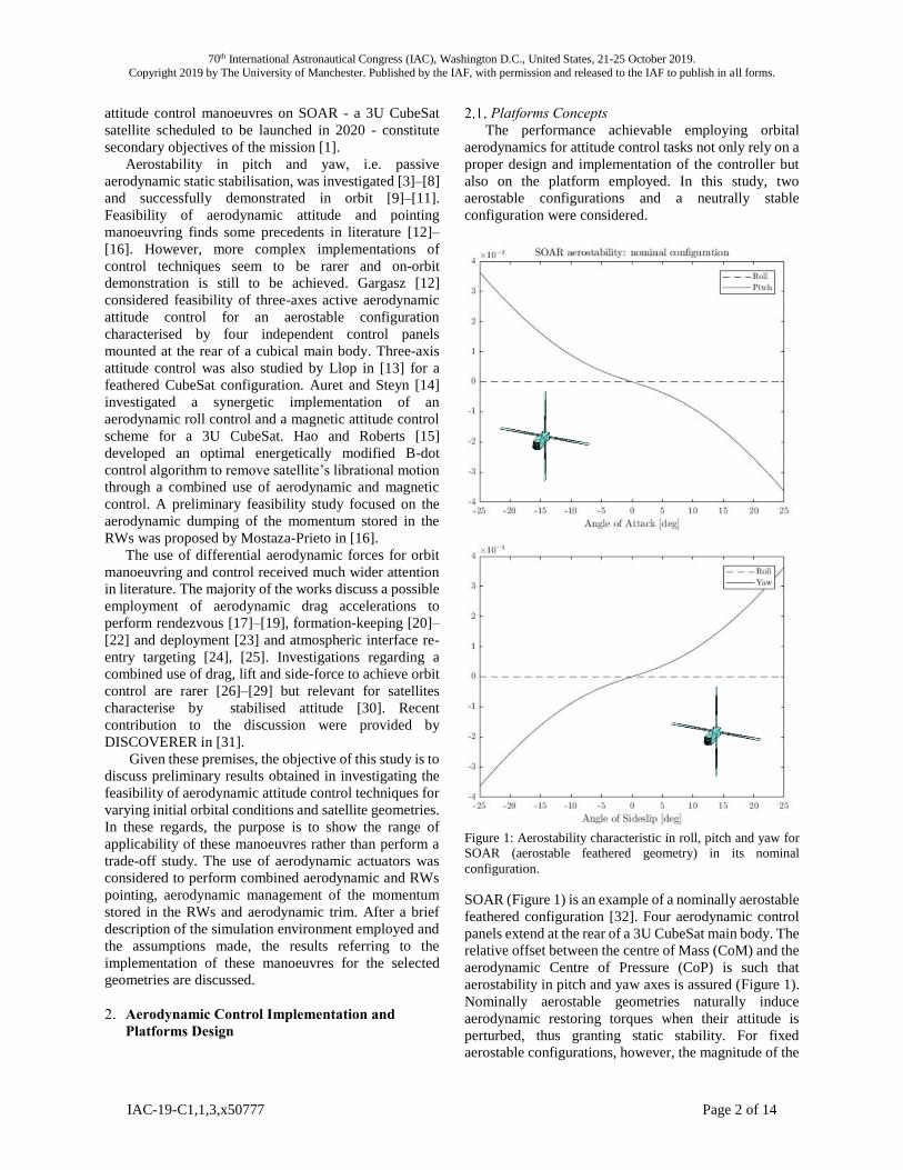
Figure 1: Aerostability characteristic in roll, pitch and yaw for
SOAR (aerostable feathered geometry) in its nominal
configuration.
SOAR (Figure 1) is an example of a nominally aerostable
feathered configuration [32]. Four aerodynamic control
panels extend at the rear of a 3U CubeSat main body. The
relative offset between the centre of Mass (CoM) and the
aerodynamic Centre of Pressure (CoP) is such that
aerostability in pitch and yaw axes is assured (Figure 1).
Nominally aerostable geometries naturally induce
aerodynamic restoring torques when their attitude is
perturbed, thus granting static stability. For fixed
aerostable configurations, however, the magnitude of the

70th International Astronautical Congress (IAC), Washington D.C., United States, 21-25 October 2019.
Copyright 2019 by The University of Manchester. Published by the IAF, with permission and released to the IAF to publish in all forms.
IAC-19-C1,1,3,x50777 Page 3 of 14
aerodynamic torques is not big enough to damp residual
rates. As a consequence the satellite persistently
oscillates about the incoming flow direction. The four
panels can be actuated independently: counter-rotation of
an opposed set of fins induces a torque about the roll axis.
Conversely, panels’ co-rotation and asymmetries in the
geometry exposed to the flow promote the generation of
aerodynamic torques in pitch and yaw. These features
make this geometry particularly suited for control and
manoeuvring in three axes.
Figure 2: Aerostability characteristic of the aerostable
shuttlecock geometry about the roll, pitch and yaw axes in its
nominal configuration.
Figure 3: Neutrally stable characteristic in roll, pitch and yaw
for the disc satellite in its nominal configuration.
The second geometry investigated is a shuttlecock
configuration (Figure 2) endowed with four control
surfaces forming an aerostabilising skirt at the rear of a
3U CubeSat main body. Control authority is achieved in
pitch and yaw letting each panel rotate about the
respective hinge. However, the control action about the
roll axis is expected to be limited because of the
restrictions imposed on the panels motion.
Table 1: Characteristic dimensions of the three geometries
considered.
Dimensions
[m]
SOAR Shuttlecock Disc
Satellite
Panel length 0.58 0.30 0.8
Panel width 0.065 0.10 0.2
Body length 0.30 0.30 0.30
Body width 0.10 0.10 0.15

70th International Astronautical Congress (IAC), Washington D.C., United States, 21-25 October 2019.
Copyright 2019 by The University of Manchester. Published by the IAF, with permission and released to the IAF to publish in all forms.
IAC-19-C1,1,3,x50777 Page 4 of 14
Finally, a nominally neutrally stable disc satellite
configuration was examined (Figure 3). Two opposed
control surfaces extend from the side of a cylindrical
main body having its lateral surface oriented along the
ram direction. The position of these along the main body
was selected so that the CoP and the CoM would
coincide. In this way, the disturbance torques
experienced by the satellite are minimised. Altering the
angles of deflection of the panels with regards to the
incoming flow causes the loss of the neutrally stable
characteristic and permits to achieve some controllability
about the roll and yaw axes.
However, aerodynamic control in pitch is not
expected to be feasible for this specific configuration
since no-offset is present along the longitudinal axis.
Characteristic dimensions of the geometries employed
are provided in Table 1.
Reference Frames Definition
The reference systems employed for the
implementation of the aerodynamic control manoeuvres
in the simulation environment are:
Earth-Centered Inertial (ECI): the ECI reference
frame is defined in the ecliptic plane of the orbit
described by the Earth about the Sun and its origin is
coincident with the centre of mass of the Earth. The XI
axis points towards the vernal equinox, the ZI axis is
directed along the axis of rotation of the Earth and YI is
defined in the ecliptic orbit plane and determined
according to the right hand rule. Since the reference
system is inertial, the reference frame does not rotate with
the Earth.
Earth-Centered Earth-Fixed (ECEF): as for the ECI,
the origin of ECEF reference frame is positioned at the
centre of mass of the Earth and the frame lies in the
ecliptic plane of the Earth’s orbit. In this case, however,
the motion of the reference frame is integral with the
Earth. The XE pointing direction is defined by the prime
meridian. The ZE axis points towards the North Pole and
the YE axis is defined according to the right hand rule.
Local-Vertical Local-Horizontal (LVLH): the LVLH
reference frame [33] has its origin located at the centre of
mass of the satellite and the XLVLH and the ZLVLH axes
defined in its orbital plane. Specifically, the XLVLH axis is
aligned with the satellite velocity vector direction while
the ZLVLH axis is directed towards the centre of mass of
the Earth. The YLVLH axis is perpendicular to the orbital
plane and it is determined according to the right hand
rule.
Body reference frame: the body reference frame is
centred at the satellite centre of mass and is rigidly fixed
to the satellite body. Axes direction definition is here
provided assuming initial alignment with LVLH.
According to this, the XB axis is chosen such that its
direction coincides with the velocity vector direction.
The ZB axis points in nadir to the centre of mass of the
Earth. The YB axis is accordingly derived by means of
the right hand rule.
Flow reference frame: determination of flow
direction is non-negligibly affected by the difficulties
encountered in the attempt of determining the vertical
component of the thermospheric wind [34]. The level of
accuracy achievable is thus limited, but approximated
results can be obtained modelling the horizontal wind
component. According to this, the flow reference frame
was defined with the XF axis pointing in the flow
direction, the ZF axis pointing towards the centre of mass
of the Earth and the YF axis pointing along the direction
defined by the right hand rule.
Geocentric Solar Ecliptic (GSE): the GSE reference
frame has the origin located at the centre of mass of the
Earth. The XS axis is aligned with the Earth-Sun
conjoining line. The ZS axis direction is determined
computing the cross product between the Earth-Sun
vector and the Earth-Sun velocity vector. Ys definition
follows the right hand rule.
Aerodynamic Manoeuvres Selection
2.3.1. Aerodynamic Pointing
A possible employment of aerodynamic torques was
evaluated to perform aerodynamic pointing, mainly with
regards to the orbital LVLH reference frame. According
to the geometry selected, the panels configuration
providing the control torque demanded to correct the
satellite attitude can be identified and selected. In the
following, the feasibility of the manoeuvre was
investigated for one axis and two axis aerodynamic
attitude control with the remaining axis/axes being
controlled by RWs. Two main scenarios are considered
for the two aerostable configurations:
1. Combined aerodynamic roll and RWs pitch and
yaw control;
2. Combined aerodynamic pitch and yaw control
and RWs roll control.
For the neutrally stable configuration, since the design do
not allow for the generation of any control torque in pitch,
the following manoeuvre was considered:
3. Aerodynamic roll control and RWs pitch and
yaw control.
It is important to mention in this context that, especially
at higher VLEO altitudes (>300 km) just coarse pointing
accuracy is expected to be achievable in the aerodynamic
controlled axis. Finer performance can be however
achieved combing aerodynamic and conventional
actuators.
2.3.2. Aerodynamic Trim
Aerodynamic trim refers to a possible employment of
the aerodynamic torques induced on the satellite to
counteract other external disturbances affecting the plant
and keep the satellite in the desired orientation.

70th International Astronautical Congress (IAC), Washington D.C., United States, 21-25 October 2019.
Copyright 2019 by The University of Manchester. Published by the IAF, with permission and released to the IAF to publish in all forms.
IAC-19-C1,1,3,x50777 Page 5 of 14
Aerodynamic trim was performed for a number of cases
study: according to what previously affirmed, the
performance achievable were evaluated implementing
the manoeuvre after the aerodynamic pointing task was
completed and the attitude was coarsely corrected to the
desired orientation. For this reason, when aerodynamic
pointing manoeuvres are performed, the panels do not
come back to the nominal configuration but are still
actuated to perform the aerodynamic trim task.
A successful implementation of this manoeuvre is of
particular interest since it can relax the actuation effort
imposed on traditional control devices (RWs) and limit
angular momentum build-up, thus effectively reducing
the frequency of desaturation manoeuvres on orbit,
especially at lower altitudes.
2.3.3. Aerodynamic Momentum Management
Aerodynamic torques can also be employed to
manage the angular momentum stored in the RWs and
avoid internal actuators saturation. Disturbing
environmental torques are characterised by periodic and
secular components. While periodic components are
characterised by a cyclic variation corresponding to the
orbital period, the secular component causes the rates in
the actuators to linearly increase, eventually leading to
saturation. When this condition occurs the plant can no
longer be controlled and the stability of the system is
compromised.
Adopting an aerodynamic dumping strategy may
prove to have some advantages over more traditional
devices usually employed to perform this task, such as
magnetorquers. The level of performances achievable
with aerodynamic and magnetic dumping is respectively
affected by the uncertainties characterising orbital
aerodynamics and by an accurate modelling of the
Earth’s magnetic field. However, aerodynamic dumping
authority is not limited to directions that are not
perpendicular to the magnetic field of the Earth.
Different performances are expected to be observed
with materials employed, variation in the environmental
conditions mainly due to solar cycle and altitude. Whilst
aerodynamic wheels desaturation appears to be
achievable [16], the time required to reduce the
momentum in the wheels to an acceptable level to
perform attitude control tasks might make this
manoeuvre impractical for actual implementation. This is
especially true if stringent requirements are imposed on
target acquisition.
According to this, a control scheme was implemented
to evaluate whether aerodynamic torques could be used
to compensate for the angular momentum accumulated in
the RWs whilst they are employed to perform attitude
control. Simulations were performed for the shuttlecock
and the feathered configuration for two different
scenarios:
1. Saturation avoidance for off-ram direction
target pointing;
2. Saturation avoidance for off-ram direction
target pointing and attitude control manoeuvre.
More insights on the controller design for this specific
task are provided in Section 3.2.
Simulation Environment
The purpose of this section is to provide some
information regarding the simulation environment used
to test the aerodynamic control manoeuvres discussed
above. These need to be intended as a common ground to
the results shown in Section 4. Any variations to what
discussed in the current section will be mentioned in the
appropriate context.
Fluctuations of the residual atmospheric density [35]
are implemented assuming quiet solar magnetic activity,
or equivalently, reduced Extremely Ultraviolet (EUV)
emissions. Estimation of thermospheric density
variations with day-to-night, seasonal-latitudinal, semi-
annual and solar cycle variations are difficult to
acknowledge with simplified exponential models. For
this reason, this work relies on the estimation of the
density values provided by the NRLMSISE-00 [36]
atmospheric model .
Including the effects of atmospheric circulation is
especially important when possible applications of
aerodynamic torques for orbital and attitude control are
investigated. For non-equatorial orbits, the thermosphere
co-rotation with the Earth introduces a disturbance in the
satellite attitude motion about the yaw axis that needs to
be addressed. Uncertainties in the estimation of the flow
direction are introduced by the thermospheric winds,
whose generation, velocity and prevailing direction is
due to the complex interaction of phenomena occurring
in the upper atmosphere, such as gradients of pressure
and reduced kinematic viscosity. At the current state of
the art, wind models offer a good description of the
horizontal components of the wind, while major
uncertainties are encountered in the estimation of the
vertical components [34]. For the set of simulations
discussed in Section 4, the effect of zonal and meridional
winds in the determination of the direction of the
incoming flow was modelled with the HWM-93 [37]–[39]
model, as suggested in the ECSS Space Environment
standard [40].
The satellite dynamics and kinematics are affected by
environmental disturbances torques and forces which
have an impact on the design and on the robustness of the
controller. Solar radiation pressure, gravity gradient and
undesired aerodynamic torques and accelerations are for
this reason included in the simulation environment.
Mathematical description of orbital perturbation effects
due to the non-uniform Earth’s gravitational field are
included considering zonal harmonics up to the fourth
degree (J4). Solar radiation pressure torques and
accelerations produced by the interaction of solar

70th International Astronautical Congress (IAC), Washington D.C., United States, 21-25 October 2019.
Copyright 2019 by The University of Manchester. Published by the IAF, with permission and released to the IAF to publish in all forms.
IAC-19-C1,1,3,x50777 Page 6 of 14
radiation with the exposed surfaces is modelled adopting
specular and diffuse reflectivity coefficients of 0.15 and
0.25, respectively. The total disturbances are evaluated,
for the current configuration, implementing a panel
method through a mesh discretisation and summing the
contributions computed for each surface. In this way, the
robustness of the controllers could also be tested against
variations in the disturbance torques experienced by the
satellite between periods of eclipse.
Given a defined geometry, the aerodynamic control
authority achievable by surface actuation is dependent on
the model employed to provide a physical description of
the mechanisms of interaction occurring between gas
particles and surface atoms [41]. For a given gas-surface
interaction (GSI) model, the induced aerodynamic
torques and forces in roll, pitch and yaw vary with the
thermal or the momentum accommodation coefficients.
According to this, the materials that constitute the surface
exposed to the flow have an impact on the expected
aerodynamic performances. For this study, Sentman’s
model [42] is employed with high thermal
accommodation coefficients (α) to represent the
behaviour and the performance expected to be achievable
at the current state of the art. In particular, α is assumed
to vary in the range 0.9-1 according to reductions of
atomic oxygen concentration with decreasing altitude
[43], [44].
The aerodynamic control authority exerted by the
panels is also limited by eventual shadowing from the
incoming flow occurring especially at high orbital
inclinations. The impact of this last effect is however
likely to be negligible if compared to other source of
uncertainties affecting the problem of orbital
aerodynamic torques estimation (e.g. reference area
definition, aerodynamic coefficients estimation,
accuracy of atmospheric and GSI models employed,
accommodation coefficients estimation and variation
with surface contamination, properties and altitudes).
According to this, as a first approximation panels
shadowing was neglected but a more rigorous analysis
would require its inclusion. In this regard, uncertainties
in the aerodynamic control torques produced in output
were taken into account through the introduction of an
error function to test the robustness of the controller
against uncertainties.
Control Strategy
Quaternion Feedback Proportional-Integral-
Derivative (PID) Control
Combined RWs and aerodynamic attitude control
was implemented adopting the quaternion feedback PID
control strategy proposed by Bang et al. [45] as a further
development of Wie et al. [46] quaternion feedback
controller. The PID form of the control law was preferred
over the original proposal [46] because the presence of
the integral term permits to reduce the steady-state error
and achieve better performances in the presence of
external disturbances. The continuous time control law is
given by [45]:
�� = 𝛾�� × �� − 𝐾𝑃𝑞𝑒 − 𝐾𝐷�� − 𝐾𝐼𝜉 (1)
Where �� is the control signal, 𝐾𝑃 , 𝐾𝐷 , 𝐾𝐼 are the constant
proportional, derivative and integral gains, 𝛾 is a positive
constant gain determining to which extent the cross-
coupling gyroscopic term is corrected, �� is the vector of
satellite angular velocity, �� is the total angular
momentum of the platform, 𝑞𝑒 is the quaternion error and
𝜉 is the integral signal. The value of this last is
determined introducing a non-linear intelligent
integrator block. This feature was implemented by the
authors [45] to prevent actuators from saturating in the
presence of large integral errors. Even though just small
angle manoeuvring is considered in this study, the
implementation of the intelligent integrator logic proved
to be advantageous because of the reduced control
authority of the RWs. More details about the controller
logic development can be found in the original
publication from the authors [45].
The values of 𝐾𝑃 , 𝐾𝐷 , 𝐾𝐼 were determined using a
Linear Quadratic Regulator (LQR) and properly selecting
the values of the matrix penalising the state variables and
the control signal to include limitations due to actuators
saturation. The value of 𝛾 was selected to be equal to 1,
so that the control signal is accordingly generated to
compensate for the gyroscopic term in its entirety. The
controller described by Eq. 1 was modified for digital
implementation considering a sampling frequency of 1
Hz. The discrete-time formulation was derived applying
backwards differentiation and implementing the
algorithm according to an incremental/velocity
formulation.
Linear Quadratic Regulator (LQR)
For the angular momentum management task, an
infinite-horizon LQR feedback loop is added to the
control scheme. The optimal control law is given by:
𝑢(𝑡) = −𝐾𝑥 (2)
where K is the optimal gain matrix corresponding to the
minimum of a defined performance index J and x is the
vector of state variables. Given the linear state space
model for the system:
��(𝑡) = 𝐴𝑥(𝑡) + 𝐵𝑢(𝑡) (3)

70th International Astronautical Congress (IAC), Washington D.C., United States, 21-25 October 2019.
Copyright 2019 by The University of Manchester. Published by the IAF, with permission and released to the IAF to publish in all forms.
IAC-19-C1,1,3,x50777 Page 7 of 14
For the infinite-horizon problem the cost function to be
minimised does not present any terminal constraint, so
that in its discrete time formulation:
𝐽 = ∑(𝑥𝑘
𝑇𝑄𝑥𝑘 + 𝑢𝑘𝑇𝑅𝑢𝑘)
∞
𝑘=0
(4)
where 𝑄 ≥ 0 and 𝑅 > 0 are symmetric positive semi-
definite penalty matrices. Specifically, 𝑄 penalises the
state variables and 𝑅 the control signal. Since the
momentum control loop operates in parallel to the
quaternion feedback PID controlling the satellite attitude,
it must be designed so that the two loops are characterised
by wide separation in frequency or, equivalently, time
response. In this way, the interference of the antagonist
momentum control loop to the attitude control loop is
minimised as much as possible. To achieve this results
the values of the two matrices described above were
accordingly selected so that the desired performances
could be achieved.
Surface Deflection Logic
The purpose of this section is to describe the logic
implemented to select the panels configuration providing
the closest match to the required control torques coming
from the quaternion feedback controller (in the case of
aerodynamic pointing) or from the optimal LQR (in the
case of momentum management).
Aerodynamic forces and torques in roll, pitch and yaw
are given by:
𝐹𝑎 = [
𝐹𝑎,𝑥
𝐹𝑎,𝑦
𝐹𝑎,𝑧
] = 0.5𝜌𝑉𝑟𝑒𝑙2 𝐶𝐹,𝐴
(7)
𝑀𝑎 = [
𝑀𝑎,𝑥
𝑀𝑎,𝑦
𝑀𝑎,𝑧
] = 0.5𝜌𝑉𝑟𝑒𝑙2 𝐶𝑀,𝑉
(8)
where 𝜌 indicates the atmospheric density, 𝑉𝑟𝑒𝑙 is the
magnitude of the relative velocity vector and 𝐶𝐹,𝐴 and
𝐶𝑀,𝑉 are the dimensional force and momentum
aerodynamic coefficients.
The computation of these last relies on a method deriving
from adapting ADBSat [16], a panel method for
aerodynamic coefficients computation available at the
University of Manchester, for control purposes.
The geometry of the satellite, discretised in a 3D
triangular mesh, is firstly imported. The algorithm then
selects, among the mesh elements that constitute the
entire surface, the ones that belongs to the main body to
the one belonging to the control paddles.
Given the current angle of attack and sideslip, the
local direction of the normal and tangential unit vectors
is computed for each element of the surface and the
dimensional normal and shear stress coefficients are
computed according to the Sentman’s model [42].
The contributions provided from the main body and
from the control panels are computed separately.
Variation of the shear stress and normal coefficients is
computed for the configurations resulting from a range of
possible combinations obtained considering the
independent rotation of the control surfaces. The number
of permutations, and thus the computational effort, is
reduced assuming a constant step to span the allowed
angular range. The overall dimensional aerodynamic
force and torque coefficients are then computed summing
the contribution coming from each element of the surface
(body panels):
𝐶𝐹,𝐴 = [
𝐶𝐹,𝑥
𝐶𝐹,𝑦
𝐶𝐹,𝑧
] = ∑(𝑐𝜏,𝑘𝜏𝑘
𝑁
𝑘=1
− 𝑐𝑝,𝑘𝑛𝑘 ) 𝐴𝑘
(5)
𝐶𝑀,𝑉 = [
𝐶𝑀,𝑥
𝐶𝑀,𝑦
𝐶𝑀,𝑧
] = ∑(𝑟𝑘 − 𝑟𝐶𝑜𝑀)
𝑁
𝑘=1
× (𝑐𝜏,𝑘𝜏𝑘 − 𝑐𝑝,𝑘𝑛𝑘 ) 𝐴𝑘
(6)
where (𝑟𝑘 − 𝑟𝐶𝑜𝑀) is the distance of each surface
element from the CoM. In this way, the aerodynamic
contribution coming from the main body is not treated as
a disturbance but is usefully employed for control
purposes. The panels configuration is finally selected
computing the minimum Euclidean distance between the
commanded torques and the computed control torques.
Results and Discussion
Shuttlecock Configuration (Aerostable)
For the aerostable shuttlecock configuration
discussed in Section 2.1, feasibility of RWs momentum
management and aerodynamic control in pitch & yaw
were investigated.
For the momentum management task, it is assumed that
the satellite is travelling a circular orbit inclined by 50°
at 250 km of altitude. The RWs are actuated to counteract
the external disturbances affecting the plant, such that a
desired offset with regards to LVLH (5° in pitch and 3°
in yaw) can be maintained. As can be seen in Figure 4,
performing this task in the lower VLEO altitude range is
quite demanding, due to the increased aerodynamic
disturbances experienced by the satellite. The full set of
RWs saturates within 25 minutes. As a

70th International Astronautical Congress (IAC), Washington D.C., United States, 21-25 October 2019.
Copyright 2019 by The University of Manchester. Published by the IAF, with permission and released to the IAF to publish in all forms.
IAC-19-C1,1,3,x50777 Page 8 of 14
Figure 4: Time histories of the Euler angles and satellite body
rates for the shuttlecock configuration when no dumping
strategy for angular momentum build-up is employed. RWs
saturation causes loss of system controllability and the satellite
starts oscillating about the flow direction.
Figure 5: Performance of the aerodynamic angular momentum
management task for the shuttlecock configuration.
consequence, control authority is lost and, because of its
aerostable characteristic in pitch and yaw (Figure 2, first
and second plot), the satellite motion shows persistent
oscillation about the flow direction.
Figure 6: Performance of the aerodynamic pitch and yaw
manoeuvre for the shuttlecock configuration. The satellite
motion about the roll axis is controlled by the RWs.
On the contrary, when the aerodynamic management
task is performed, the angular momentum stored in each
wheel is kept very close to the initial null value and
reasonably distant from the upper and lower saturation
limits (Figure 5, second picture from the top). The third
plot in Figure 5 shows the same information of the second
plot from the top, but it provides an enlarged view on the
variation of the angular momentum in each wheel
adopting a smaller scale. Moreover, the task appears to
be performed with reasonable panels activity (Figure 5,
fourth and fifth plot from the top) and without interfering
with the pointing task performed by the RWs in parallel
(Figure 5, top). However, selection of high drag
configurations may lead to a considerable increase in the
orbital rate of decay. Further analysis assessing variations
in the aerodynamic drag profile thus need to be
performed to better evaluate the range of applicability of
this manoeuvre. A possible cost-efficient solution may be
70th International Astronautical Congress (IAC), Washington D.C., United States, 21-25 October 2019.
Copyright 2019 by The University of Manchester. Published by the IAF, with permission and released to the IAF to publish in all forms.
IAC-19-C1,1,3,x50777 Page 9 of 14
found in employing Atmospheric Breathing Electric
Propulsion (ABEP) systems [47] .
Feasibility of aerodynamic pointing manoeuvring in
pitch and yaw has been investigated for a 280 km circular
orbit inclined at 50°. Given an initial offset in roll, pitch
and yaw of 5°, -10° and 7° the panels and the RWs are
actuated to correct the attitude to achieve alignment with
the LVLH reference frame. During theattitude
stabilisation task, the aerodynamic panels succeed in
correcting the attitude in pitch and yaw without any
interference from the RWs.. Conventional actuators
provide the demanded control torque exclusively in roll
(Figure 6, third plot). After the attitude has been
stabilised about the desired target, the panels are moved
to their nominal configuration (45°) and external
environmental disturbances are compensated by the RWs.
Because of the perturbation introduced by atmospheric
co-rotation in yaw, the panels activity is quite intense
(Figure 6, fourth and fifth plot). A possible improvement
in this regard might be achievable adopting smaller gains
for the quaternion feedback PID loop.
Disc Configuration (Neutrally Stable)
Due to the limited controllability in pitch axis,
possible employment of aerodynamic torques for
stabilisation of the roll attitude has been investigated for
the disc satellite geometry described in Section 2.1.
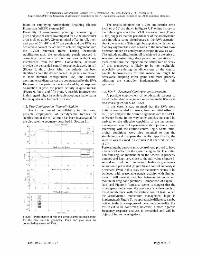
Figure 7: Performance of roll-axis aerodynamic attitude control
for the disc satellite geometry. Pitch and yaw axes are
controlled by means of RWs.
The results obtained for a 280 km circular orbit
inclined at 50° are shown in Figure 7. The time history of
the Euler angles about the LVLH reference frame (Figure
7, top) suggests that the performance of the aerodynamic
task introduce some disturbances in the RWs actuation
about the yaw axis. This might be explained with the fact
that any asymmetries with regards to the incoming flow
direction induce an aerodynamic torque in yaw as well.
The attitude stabilisation in roll is achieved at the price of
selecting undesired high drag panels configurations. In
these conditions, the impact on the orbital rate of decay
of this manoeuvre is likely to be non-negligible,
especially considering the dimensions of the control
panels. Improvements for this manoeuvre might be
achievable adopting lower gains and more properly
adjusting the controller implementation for this
geometry.
SOAR - Feathered Configuration (Aerostable)
A possible employment of aerodynamic torques to
avoid the build-up of angular momentum in the RWs was
also investigated for SOAR [32].
In this case, it was assumed that the RWs were
initially commanded to restore, from an initial offset in
roll, pitch and yaw, the desired alignment with the LVLH
reference frame. In this way better conclusions could be
derived on the effective capability of the momentum
management control loop to achieve its objective without
interfering with the attitude control logic. Same initial
orbital conditions were also assumed to run the
simulations and compare the results. Specifically, the
satellite was assumed in a circular 200 km orbit inclined
at 70°.
Performing the aerodynamic control loop proved to have
a beneficial effect on the system (Figure 9). The initial
non-null angular momentum in the wheels is properly
dumped and kept very close to the null value (Figure 9,
second and third plot from the top). In this way, actuators
saturation is prevented (Figure 8) and control authority is
preserved. Even in this case, the manoeuvre seems to be
achieved with reasonable panels activity with limited,
even if still present, switches between minimum and
maximum drag configurations. Comparison of Figure 8
(top) and Figure 9 (top) also seems to suggest that the
time separation between the two loops is wide enough to
avoid interference with the attitude control task. When
the aerodynamic momentum management logic is
implemented (Figure 9), no appreciable difference can be
noticed in the time response of the attitude controller. For
this result to be confirmed, however, a more rigorous
frequency response analysis is demanded and will be
object of future investigations.

70th International Astronautical Congress (IAC), Washington D.C., United States, 21-25 October 2019.
Copyright 2019 by The University of Manchester. Published by the IAF, with permission and released to the IAF to publish in all forms.
IAC-19-C1,1,3,x50777 Page 10 of 14
Figure 8: Time history of the attitude motion about the LVLH
reference frame for the aerostable feathered configuration
(SOAR) when no dumping strategy is employed. After
actuators saturation, control authority is lost and undamped
oscillations are observed.
The feasibility of an aerodynamic roll control manoeuvre
was investigated for the feathered configuration as well.
Given an initial offset in LVLH of 5° in roll, -5° in pitch
and 5° in yaw, the aerodynamic panels are actuated in
order to stabilise the satellite attitude and to maintain a
desired offset in roll with regards to the LVLH reference
frame of -3°. Initial orbital conditions include a null
eccentricity orbit characterised by an inclination of 50°
and an altitude of 200 km. The results shown in Figure
10 seem to be quite promising, with settling time being
of the order of ~300s for this manoeuvre (Figure 10, top).
As can be seen in the third plot from the top in Figure 10
the aerodynamic pointing manoeuvre is achieved with no
interference from the RWs. As expected, during the
aerodynamic pointing phase the panels algorithm
preferentially selects panels counter-rotation to increase
the control authority in roll (Figure 10, fourth and fifth
plot). After the satellite has been stabilised about the
desired pointing direction, the panels are not returned to
their nominal configurations, but are still actuated to
maintain the desired attitude by performing aerodynamic
trim. The overall aerodynamic pointing and trim
manoeuvre appears to be achievable with a reasonable
control effort imposed on the panels. These results
however can be improved limiting the selection of high
aerodynamic drag configurations introducing a saturation
avoidance logic within the panels algorithm.
Figure 9: Performance of the aerodynamic momentum
management task for the feathered configuration (SOAR).
Time response separation between the attitude and the
momentum management loop is investigated assuming an
initial pointing manoeuvre.
Aerodynamic control of the satellite motion about the
pitch and yaw axes was investigated for SOAR as well.
Three-axes attitude control is achieved employing RWs
exclusively for roll axis control. Even in this case,
aerodynamic trim about the pitch and yaw axes was
considered. The panels are accordingly actuated after the
pointing control task has been achieved (Figure 11,
bottom). Aerodynamic disturbances in roll are however
still compensated by RWs. Simulations were run for a
circular orbit at 250 km with an inclination of 56°. An
initial offset of 20° in roll, -10° in yaw and 12° was
assumed with regards to LVLH.
This scenario is more challenging compared to the
aerodynamic roll control one. This not only depends on
the fact that control is to be provided contemporary in
two axes but also on the presence of increased
disturbances affecting the performance achievable with
aerodynamic actuation. Satellite in non-equatorial orbits

70th International Astronautical Congress (IAC), Washington D.C., United States, 21-25 October 2019.
Copyright 2019 by The University of Manchester. Published by the IAF, with permission and released to the IAF to publish in all forms.
IAC-19-C1,1,3,x50777 Page 11 of 14
experience disturbances in yaw due to atmosphere co-
rotation with the Earth. According to this, a superior
control effort is required to achieve the desired control
action. This consideration is confirmed by the time
histories of panels activity (Figure 11, fourth and fifth
plot), which are considerably more intense than the one
observed for the aerodynamic roll control case (Figure 10,
fourth and fifth plot), and by the performances which are
coarser in yaw. Despite the results achieved,
improvements can be applied to relax the control effort
demanded on the aerodynamic actuators by reducing the
panels algorithm sensitivity. Small variations in the
demanded control torque seem to have the effect of
making the panels unnecessarily switch between the
nominal configuration and the “control” configurations.
Improvements may comprise the introduction of the
saturation avoidance control logic mentioned before or
the employment of lower gains for the quaternion
feedback PID.
Figure 10: Performance of the combined aerodynamic roll and
RWs pitch and yaw pointing manoeuvre. Aerodynamic trim
about the roll axis is performed to maintain the desired offset in
roll with regards to LVLH.
Figure 11: Performance of the aerodynamic pointing
manoeuvre about the pitch & yaw axes for SOAR. Motion
about the roll axis is controlled by the RWS. After the initial
offset is nulled out, the aerodynamic panels are still employed
to reject external disturbances in pitch and yaw.
Conclusion and Future Developments
The feasibility of a set of aerodynamic attitude
control manoeuvres for operations in VLEO was
investigated for two aerostable geometries (shuttlecock
and SOAR) and a nominally neutrally stable
configuration (disc satellite). To preserve generality, the
investigation concerned varying initial orbital and
pointing conditions. In particular, VLEO altitudes were
selected according to the expected suitability of orbital
aerodynamics control during periods of reduced solar
activity [48].
The aerodynamic control manoeuvres examined
comprise combined aerodynamic and RWs attitude
control, aerodynamic trim and aerodynamic management
of the angular momentum stored in the RWs. The control
signal for the aerodynamic pointing and trim task is
provided by the digital implementation of the constant
gain quaternion feedback PID + intelligent integrator
controller proposed by Bang et al. [45]. The momentum
70th International Astronautical Congress (IAC), Washington D.C., United States, 21-25 October 2019.
Copyright 2019 by The University of Manchester. Published by the IAF, with permission and released to the IAF to publish in all forms.
IAC-19-C1,1,3,x50777 Page 12 of 14
management task is implemented according to a classical
discrete-time infinite-horizon LQR.
The results obtained for the feathered and the
shuttlecock configurations seem to be particularly
promising. However, some further developments are
needed. The level of detail used in the implementation of
the control logics employed for this works is limited.
Design and implementation of control algorithms is
considerably driven by the requirements imposed on the
platform considered. For this study, a description
characterised by a lower specification level was preferred
to favour adaption to different geometries and preserve
generality. Implementation on a real platform like SOAR,
however, requires addressing constraints to improve the
confidence of the results obtained. Future developments
will thus see the inclusion of software and hardware
limitations (sensor noise and deadbands, panels
deflection rates, data storage and memory etc.) as well as
improvements to the logic used to determine the optimal
panels configuration providing the commanded control
signal. The impact of aerodynamic attitude control
manoeuvres on orbit perturbation will also be addressed
to better discuss the advantages achievable over the
employment of conventional actuators.
Acknowledgements
The DISCOVERER project has received funding
from the European Union’s Horizon 2020 research and
innovation programme under grant agreement No
737183. Disclaimer: this publication reflects only the
views of the authors. The European Commission is not
liable for any use that may be made of the information
contained therein.
References
[1] P. C. E. Roberts et al., “Discoverer - Radical
redesign of earth observation satellites for
sustained operation at significantly lower
altitudes,” in Proceedings of the International
Astronautical Congress, IAC, 2017, vol. 14, no.
September, pp. 25–29.
[2] B. Streetman, J. Shoer, and L. Singh,
“Limitations of scaling momentum control
strategies to small spacecraft,” in IEEE
Aerospace Conference Proceedings, 2017.
[3] V. V. Beletsky, “Motion of an Artificial Satellite
about its Center of Mass,” National Aeronautics
and Space Administration (NASA), U.S.A.,
Washington, D.C., 1965.
[4] L. Meirovitch and F. B. J. Wallace, “On the
Effect of Aerodynamic and Gravitational
Torques on the Attitude Stability of Satellites.,”
AIAA J., vol. 4, no. 12, pp. 2196–2202, 1966.
[5] M. A. Frik, “Attitude Stability of Satellites
Subjected to Gravity Gradient and Aerodynamic
Torques,” AIAA J., vol. 8, no. 10, pp. 1780–1785,
1970.
[6] R. Ravindran and P. C. Hughes, “Optimal
Aerodynamic Attitude Stabilization of Near-
Earth Satellites,” J. Spacecr. Rockets, vol. 9, no.
7, pp. 499–506, 1972.
[7] M. L. Psiaki, “Nanosatellite Attitude
Stabilization Using Passive Aerodynamics and
Active Magnetic Torquing,” J. Guid. Control.
Dyn., vol. 27, no. 3, pp. 347–355, 2004.
[8] S. A. Rawashdeh and J. E. Lumpp,
“Aerodynamic Stability for CubeSats at ISS
Orbit,” J. Small Satell., vol. 2, no. 1, pp. 85–104,
2013.
[9] M. R. Drinkwater et al., “The GOCE gravity
mission: ESA’S first core earth explorer,”
European Space Agency, (Special Publication)
ESA SP, no. SP-627. pp. 1–7, 2007.
[10] V. A. Sarychev, S. A. Mirer, A. A. Degtyarev,
and E. K. Duarte, “Investigation of equilibria of
a satellite subjected to gravitational and
aerodynamic torques with pressure center in a
principal plane of inertia,” Celest. Mech. Dyn.
Astron., vol. 100, no. 4, pp. 301–318, 2008.
[11] J. Armstrong, C. Casey, G. Creamer, and G.
Dutchover, “Pointing Control for Low Altitude
Triple Cubesat Space Darts,” in Small Satellite
Conference, 2009, no. 202, pp. 1–8.
[12] M. L. Gargasz, “Optimal Spacecraft Attitude
Control Using Aerodynamic Torques,” Air Force
Institute of Technology, 2007.
[13] J. V. Llop, P. C. E. Roberts, and Z. Hao,
“Aerodynamic attitude and orbit control
capabilities of the ΔDSAT cubesat,” Adv.
Astronaut. Sci., vol. 151, no. February, pp. 321–
332, 2014.
[14] J. Auret and W. H. Steyn, “Design of an
aerodynamic attitude control system for a
CubeSat,” 62nd Int. Astronaut. Congr. 2011, IAC
2011, vol. 11, no. January 2011, pp. 9009–9017,
2011.
[15] Z. Hao and P. C. E. Roberts, “Using
Aerodynamic Torques To Aid Detumbling Into
an Aerostable State,” 67th Int. Astronaut.
Congr., no. September, pp. 26–30, 2016.
[16] D. Mostaza-Prieto, “Characterisation and
Applications of Aerodynamic Torques on
Satellites,” University of Manchester, 2017.
[17] R. Bevilacqua and M. Romano, “Rendezvous
Maneuvers of Multiple Spacecraft Using
Differential Drag Under J2 Perturbation,” J.
Guid. Control. Dyn., vol. 31, no. 6, pp. 1595–
1607, 2008.
[18] D. Pérez and R. Bevilacqua, “Differential drag
spacecraft rendezvous using an Adaptive
Lyapunov Control strategy,” Adv. Astronaut.

70th International Astronautical Congress (IAC), Washington D.C., United States, 21-25 October 2019.
Copyright 2019 by The University of Manchester. Published by the IAF, with permission and released to the IAF to publish in all forms.
IAC-19-C1,1,3,x50777 Page 13 of 14
Sci., vol. 145, pp. 973–991, 2012.
[19] L. Dell’ Elce and G. Kerschen, “Optimal
propellantless rendez-vous using differential
drag,” Acta Astronaut., vol. 109, pp. 112–123,
2015.
[20] G. B. Palmerini, S. Sgubini, and G. Taini,
“Spacecraft orbit control using air drag,” in
International Astronautical Conference, 2014,
no. January 2005.
[21] O. Ben-Yaacov and P. Gurfil, “Long-Term
Cluster Flight of Multiple Satellites Using
Differential Drag,” J. Guid. Control. Dyn., vol.
36, no. 6, pp. 1731–1740, 2013.
[22] C. Lambert, B. S. Kumar, J. F. Hamel, and A. Ng,
“Implementation and performance of formation
flying using differential drag,” Acta Astronaut.,
vol. 71, pp. 68–82, 2012.
[23] H. Leppinen, “Deploying a single-launch
nanosatellite constellation to several orbital
planes using drag maneuvers,” Acta Astronaut.,
vol. 121, pp. 23–28, 2015.
[24] J. Virgili, P. C. E. Roberts, and N. C. Hara,
“Atmospheric Interface Reentry Point Targeting
Using Aerodynamic Drag Control,” J. Guid.
Control. Dyn., vol. 38, no. 3, pp. 403–413, 2015.
[25] S. Omar and R. Bevilacqua, “Guidance,
navigation, and control solutions for spacecraft
re-entry point targeting using aerodynamic
drag,” Acta Astronaut., 2018.
[26] M. Horsley, S. Nikolaev, and A. Pertica, “Small
Satellite Rendezvous Using Differential Lift and
Drag,” J. Guid. Control. Dyn., vol. 36, no. 2, pp.
445–453, 2013.
[27] X. Shao, M. Song, D. Zhang, and R. Sun,
“Satellite rendezvous using differential
aerodynamic forces under J2 perturbation,”
Aircr. Eng. Aerosp. Technol., vol. 87, no. 5, pp.
427–436, 2015.
[28] B. Smith, R. Boyce, L. Brown, and M. Garratt,
“Investigation into the Practicability of
Differential Lift-Based Spacecraft Rendezvous,”
Journal of Guidance, Control, and Dynamics,
vol. 40, no. 10. pp. 1–8, 2017.
[29] R. Sun, J. Wang, D. Zhang, Q. Jia, and X. Shao,
“Roto-Translational Spacecraft Formation
Control Using Aerodynamic Forces,” J. Guid.
Control. Dyn., vol. 40, no. 10, pp. 2556–2568,
2017.
[30] P. Moore, “The effect of Aerodynamc Lift on
Satellite Orbits,” Planet Sp. Sci., vol. 33, no. 5,
pp. 479–491, 1985.
[31] C. Traub, G. H. Herdrich, and S. Fasoulas,
“Influence of energy accommodation on a robust
spacecraft rendezvous maneuver using
differential aerodynamic forces,” CEAS Sp. J.,
2019.
[32] N. H. Crisp et al., “SOAR - Satellite for orbital
aerodynamics research,” in Proceedings of the
International Astronautical Congress, IAC,
2018.
[33] F. L. Markley and J. L. Crassidis, Fundamentals
of spacecraft attitude determination and control.
2014.
[34] M. F. Larsen and J. W. Meriwether, “Vertical
winds in the thermosphere,” J. Geophys. Res. Sp.
Phys., vol. 117, no. 9, pp. 1–10, 2012.
[35] E. Doornbos and H. Klinkrad, “Modelling of
space weather effects on satellite drag,” Adv. Sp.
Res., vol. 37, no. 6, pp. 1229–1239, 2006.
[36] J. M. Picone, A. E. Hedin, D. P. Drob, and A. C.
Aikin, “NRLMSISE-00 empirical model of the
atmosphere: Statistical comparisons and
scientific issues,” J. Geophys. Res. Sp. Phys., vol.
107, no. A12, pp. 0–16, 2002.
[37] A. E. Hedin, N. W. Spencer, and T. L. Killeen,
“Empirical global model of upper thermosphere
winds based on atmosphere and dynamics
explorer satellite data,” J. Geophys. Res., vol. 93,
no. A9, pp. 9959–9978, 1988.
[38] A. E. Hedin et al., “Revised global model of
thermosphere winds using satellite and ground-
based observations,” J. Geophys. Res., vol. 96,
no. A5, pp. 7657–7688, 1991.
[39] D. P. Drob et al., “An empirical model of the
Earth’s horizontal wind fields: HWM07,” J.
Geophys. Res. Sp. Phys., vol. 113, no. 12, pp. 1–
18, 2008.
[40] European Cooperation For Space
Standardization (ECSS), “ECSS-E-ST-10-04C
Space environment,” Noordwijk, The
Netherlands, 2008.
[41] D. Mostaza Prieto, B. P. Graziano, and P. C. E.
Roberts, “Spacecraft drag modelling,” Prog.
Aerosp. Sci., vol. 64, pp. 56–65, 2014.
[42] L. H. Sentman, “Free molecule flow theory and
its application to the determination of
aerodynamic forces,” Sunnyvale, California,
1961.
[43] B. A. Banks, K. K. de Groh, and S. K. Miller,
“Low Earth Orbital Atomic Oxygen Interactions
With Materials,” NASA/TM-2004-213400, no.
November. Glenn Research Center, Cleveland,
Ohio, pp. 1–19, 2004.
[44] K. Moe and M. M. Moe, “Gas-surface
interactions and satellite drag coefficients,”
Planet. Space Sci., vol. 53, no. 8, pp. 793–801,
2005.
[45] H. Bang, M. J. Tahk, and H. D. Choi, “Large
angle attitude control of spacecraft with actuator
saturation,” Control Eng. Pract., vol. 11, no. 9,
pp. 989–997, 2003.
[46] B. Wie, H. Weiss, and A. Arapostathis,
70th International Astronautical Congress (IAC), Washington D.C., United States, 21-25 October 2019.
Copyright 2019 by The University of Manchester. Published by the IAF, with permission and released to the IAF to publish in all forms.
IAC-19-C1,1,3,x50777 Page 14 of 14
“Quarternion feedback regulator for spacecraft
eigenaxis rotations,” J. Guid. Control. Dyn., vol.
12, no. 3, pp. 375–380, 1989.
[47] F. Romano, T. Binder, G. Herdrich, S. Fasoulas,
and T. Schönherr, “Air-Intake Design
Investigation for an Air-Breathing Electric
Propulsion System,” Int. Electr. Propuls. Conf.,
pp. 1–27, 2015.
[48] N. H. Crisp et al., “Demonstration of
Aerodynamic Control Manoeuvres in Very Low
Earth Orbit using SOAR (Satellite for Orbital
Aerodynamics Research),” 70th Int. Astronaut.
Congr., no. October, pp. 21–25, 2019.