concepts of seismic-resistant design - · pdf fileconcepts of seismic-resistant design ......
TRANSCRIPT

FEMA 451B Topic 7 Notes Earthquake Engineering 7 - 1
Instructional Material Complementing FEMA 451, Design Examples Design Concepts 7 - 1
CONCEPTS OF SEISMIC-RESISTANT DESIGN
This topic introduces the concepts of seismic-resistant design from a philosophical perspective. For this reason, the NEHRP Recommended Provisions, the International Building Code, and various standards are referenced directly.The slide shown is a ductile concrete moment resisting frame structure (parking garage) that collapsed during the Northridge earthquake. Note that there is tremendous deformation capacity in the columns of the perimeter moment frame. The collapse was actually due to the loss of several interior “nonstructural” gravity columns that were not sufficiently detailed to accommodate the large inelastic displacement demands imposed by the earthquake. More is said about this in a later slide so do not over emphasize here. The point is that many “secondary” items are, in fact, of primary importance.

FEMA 451B Topic 7 Notes Earthquake Engineering 7 - 2
Instructional Material Complementing FEMA 451, Design Examples Design Concepts 7 - 2
1. Develop concept (design philosophy)2. Select structural system3. Establish performance objectives4. Estimate external seismic forces5. Estimate internal seismic forces (linear analysis)6. Proportion components7. Evaluate performance (linear or nonlinear analysis)8. Final detailing9. Quality assurance
Steps in the Seismic Design of a Building
In this topic, only the first three bullet items are addresses. More is said about the other points when the NEHRP Recommended Provisions are discussed. The points are supposed to be something of a chronological list of design considerations. However, performance objectives could be listed as either Point 2 or 3 because the structural system and the performance objective go hand-in-hand.

FEMA 451B Topic 7 Notes Earthquake Engineering 7 - 3
Instructional Material Complementing FEMA 451, Design Examples Design Concepts 7 - 3
Seismic Design Practice in the United States
• Seismic requirements provide minimum standards for use in building design to maintain public safety in an extreme earthquake.
• Seismic requirements safeguard against major failures and loss of life – they DO NOT necessarily limit damage, maintain function, or provide for easy repair.
• Design forces are based on the assumption that a significant amount of inelastic behavior will take place in the structure during a design earthquake.
The points from the next three slides come from the Commentary to the 2003 NEHRP Recommended Provisions; hence, they are elated to new buildings. These points emphasize that life safety is the primary design objective. Even though the Provisions is implicitly designed to control damage from frequent low intensity earthquakes, there is no objective criteria to guarantee such performance. After the 1994 Northridge earthquake, damage to many buildings designed under “modern” provisions exhibited significant damage. This led to a re-thinking of the seismic provisions in the United States and to the move towards performance-based design.

FEMA 451B Topic 7 Notes Earthquake Engineering 7 - 4
Instructional Material Complementing FEMA 451, Design Examples Design Concepts 7 - 4
Seismic Design Practice in the United States continued
• For reasons of economy and affordability, the design forces are much lower than those that would be required if the structure were to remain elastic.
• In contrast, wind-resistant structures are designed toremain elastic under factored forces.
• Specified code requirements are intended to provide forthe necessary inelastic seismic behavior.
• In nearly all buildings designed today, survival in largeearthquakes depends directly on the ability of their framing systems to dissipate energy hysteretically while undergoing (relatively) large inelastic deformations.
These two points are the key to seismic-resistant design. If possible, it would certainly be desirable to design structures to remain elastic during extreme events. However, elastic seismic forces can be several times the wind force and design for such forces is simply not economically feasible.By allowing yielding at some fraction of the elastic seismic demand, the design forces are reduced and the desired economy is achieved. However, for the design to be viable, the system must be detailed to accommodate the inelastic deformations that will occur after yielding.

FEMA 451B Topic 7 Notes Earthquake Engineering 7 - 5
Instructional Material Complementing FEMA 451, Design Examples Design Concepts 7 - 5
The Difference Between Wind-Resistant Designand Earthquake-Resistant Design
For Wind:Excitation is an applied pressure or force on the facade.Loading is dynamic but response is nearly static for most structures.Structure deforms due to applied force.Deformations are monotonic (unidirectional).Structure is designed to respond elastically under factored loads.The controlling life safety limit state is strength.Enough strength is provided to resist forces elastically.
Designs to resist wind forces and seismic forces are similar only in the fact that load effects are represented by horizontal forces acting at the story levels. In fact, part of the “appeal” of the equivalent lateral force (ELF) method is that the application of external loads and the computation of member forces for design is the same as it is for wind. For most buildings, dynamic wind response may be neglected. However, for very flexible buildings and for buildings of unusual shape, aeroelastic interaction between the wind load and structural response is possible, leading to a true dynamic response in the structure.A key point to make is that under wind, the response is assumed to be elastic. In fact, significant inelastic response would be impossible because system stability would be impaired, and overall collapse could result.

FEMA 451B Topic 7 Notes Earthquake Engineering 7 - 6
Instructional Material Complementing FEMA 451, Design Examples Design Concepts 7 - 6
TimeP
ress
ure
F
δ
F
δ
Factored 50 yr windUnfactored 50 yr wind
10 yr wind
First significantyield
Behavior Under Wind Excitation
Wind load is actually a pressure applied to the façade of the building. An assumed pressure variation is shown. Note that the pressure has a non-zero static component and a time-varying (gust response) component. The static pressure component is proportional to the velocity of the wind squared, and the velocity increases along the height. Both windward and leeward pressures exist and are typically integrated over the surface area to produce story forces. Although the story forces will eventually be transferred to floor diaphragms, the forces do not originate in the diaphragms (seismic contrast to be presented later).Note that the force-displacement plot shows three points -- 10 year wind, 50 year wind, and factored 50 year wind. The 10 year wind is used for serviceability issues (drift) and the factored 50 year wind is used for design (assuming strength based design). Under the factored 50 year wind, the structure is still responding in a linear elastic fashion. (By linear, we mean no yielding of steel or crushing of concrete. Cracking of concrete will occur under the factored 50 year wind (and perhaps the 10 year wind).

FEMA 451B Topic 7 Notes Earthquake Engineering 7 - 7
Instructional Material Complementing FEMA 451, Design Examples Design Concepts 7 - 7
For Earthquake:Excitation is an applied displacement at the base.Loading and response are truly dynamic.Structural system deforms as a result of inertial forces.Deformations are fully reversed.Structure is designed to respond inelastically under factored loads.Controlling life safety limit state is deformability.Enough strength is provided to ensure that inelastic deformation
demands do not exceed deformation capacity.
The Difference Between Wind-Resistant Designand Earthquake-Resistant Design
Now the seismic contrast is presented.Emphasize that the load effect is actually a displacement (acceleration) applied to the ground. Forces develop in the structure because of the inertial resistance to the ground motion. The response is truly dynamic.The deformations are reversed -- there will be as much positive displacement as there will be negative displacement during the same event.For extreme events, the response will be inelastic. If fact, in areas of high seismicity, inelastic response can even be expected for the moderate earthquakes that occur every 10 years or so.Although design forces are developed in the members, the true limit state is deformability. If fact, it does not matter how strong the structure is as long as it can be demonstrated that the strength can be sustained over several cycles of inelastic deformation.

FEMA 451B Topic 7 Notes Earthquake Engineering 7 - 8
Instructional Material Complementing FEMA 451, Design Examples Design Concepts 7 - 8
TimeG
roun
d D
isp.
F
δ
Behavior Under Seismic Excitation(Elastic Response)
F
δ
δG
Factored seismicelastic strengthdemand
Factored wind
In general, it is not economicallyfeasible to design structures torespond elastically to earthquakeground motions.
The first cycle of seismic loading. Note that the time-history plot shows ground displacement. In the frame shown, the ground is moving to the left and the structure is lagging behind. Inertial forces develop due to the ground motion and the dynamic response of the structure relative to the ground.For the purposes of detailing the elements, only the deformation relative to the ground is important.The X-Y plot shows what the elastic response would be if the structure did not yield and, for comparison, it shows the design strength under wind.

FEMA 451B Topic 7 Notes Earthquake Engineering 7 - 9
Instructional Material Complementing FEMA 451, Design Examples Design Concepts 7 - 9
TimeG
roun
d D
isp. F
δ
Behavior Under Seismic Excitation(Inelastic Response)
F
δ
δG
Loading
The structure has now been loaded well beyond yield. This is the load beyond significant yield as all previous cycles have been elastic. Inelastic deformations have not yet reversed.

FEMA 451B Topic 7 Notes Earthquake Engineering 7 - 10
Instructional Material Complementing FEMA 451, Design Examples Design Concepts 7 - 10
TimeG
roun
d D
isp.
F
δ
F
δ
δG
Behavior Under Seismic Excitation(Inelastic Response)
Unloading
Deformationreversal
Now the ground is moving back to the right, and deformations and forces are reversed. The structure yields in the opposite direction.Note that it has been assumed that unloading occurs at the initial stiffness.

FEMA 451B Topic 7 Notes Earthquake Engineering 7 - 11
Instructional Material Complementing FEMA 451, Design Examples Design Concepts 7 - 11
TimeG
roun
d D
isp.
F
δ
F
δ
δG
Behavior Under Seismic Excitation(Inelastic Response)
Reloading
The structure is moving to the left again, and deformations again reverse, “closing the loop” for the first time. This behavior may be repeated five to ten times during an earthquake so the structure must be detailed to sustain repeated inelastic deformation reversals.While some significant loss of stiffness will occur (and is inevitable), significant loss of strength must be avoided.

FEMA 451B Topic 7 Notes Earthquake Engineering 7 - 12
Instructional Material Complementing FEMA 451, Design Examples Design Concepts 7 - 12
Stress or force or moment
δuδy
u
y
δμ
δ=
Definition of Ductility, μ
Strainor displacementor rotation
Hysteresiscurve
Definition of ductility. Recall the behavioral hierarchy presented in the topic on inelastic analysis of single-degree-of-freedom (SDOF) systems. Hysteresis is the process of repeatedly yielding. The locus of the force deformation curve is a hysteresis curve or loop.Generally speaking, the greater the achievable ductility without significant strength loss the better.

FEMA 451B Topic 7 Notes Earthquake Engineering 7 - 13
Instructional Material Complementing FEMA 451, Design Examples Design Concepts 7 - 13
Stress or force or moment
Definition of Energy Dissipation, Θ
Strainor displacementor rotation
Area = Θ = energy dissipatedUnits = force x displacement
The area within the hysteresis loop is the energy dissipated BY ONE FULL CYCLE of deformation. The dissipated energy is irrecoverable. The total hysteretic energy dissipation will be the sum of the areas for all loops. The accumulated hysteretic energy dissipation is the total energy dissipated up to some point in time.Note that the pushover analysis method uses the energy dissipated in one cycle to estimate the viscous damping for an equivalent linear system.

FEMA 451B Topic 7 Notes Earthquake Engineering 7 - 14
Instructional Material Complementing FEMA 451, Design Examples Design Concepts 7 - 14
Basic Earthquake EngineeringPerformance Objective (Theoretical)
Demand Supplyμ μ≤
Demand SuppliedΘ ≤ Θ
An adequate design is accomplished when a structureis dimensioned and detailed in such a way that thelocal ductility demands (energy dissipation demands)are smaller than their corresponding capacities.
This is the basic seismic-resistant design rule.In the NEHRP Recommended Provisions, the supplied ductility (energy dissipation) is implied for a variety of systems. If the critical regions of the structure are detailed according to the Provisions AND if the total deformation demand does not exceed, for example, 2% drift, then the basic performance objective is met.

FEMA 451B Topic 7 Notes Earthquake Engineering 7 - 15
Instructional Material Complementing FEMA 451, Design Examples Design Concepts 7 - 15
Concept of Controlled Damage
Seismic input energy = ES + EK + ED + EH
ES = Elastic strain energy
EK = Kinetic energy
ED = Viscous damping energy
EH = Hysteretic energy
Even though life safety is the primary concern, it is often desirable to explicitly control damage. One of the most efficient ways to do so is through the damage index, which is a function of the accumulated hysteretic energy dissipation, EH. In addition to EH, there are three other energy components. Like hysteretic energy, the damping energy is cumulative. Both kinetic energy and strain energy are instantaneous. The vast majority of the seismic energy is represented by the damping and hysteretic energy.

FEMA 451B Topic 7 Notes Earthquake Engineering 7 - 16
Instructional Material Complementing FEMA 451, Design Examples Design Concepts 7 - 16
Typical Energy Time History
Damping energy
Hysteretic energy
Kinetic + strain energy
This is an energy time-history taken directly from NONLIN. The red portion of the diagram represents the hysteretic energy and the green portion represents the damping energy. Kinetic and strain energy, shown in yellow, are barely visible at the top of the diagram. Every time the system loads back to a yielded state, the hysteretic energy increases. The vertical blue lines indicate a new yield event has occurred.After about 25 seconds into the response, there is no increase in hysteretic energy because no new yield events have occurred. There are only marginal increases in damping energy because the response is pretty flat after about 35 seconds.

FEMA 451B Topic 7 Notes Earthquake Engineering 7 - 17
Instructional Material Complementing FEMA 451, Design Examples Design Concepts 7 - 17
max 0.15 H
ult y ult
EDamageF
δδ δ
= +
• Yielding is necessary for affordable design.
• Yielding causes hysteretic energy dissipation.
• Hysteretic energy dissipation causes damage.
Therefore, damage is necessary foraffordable design
Several measures of damage have been proposed and this is one of the simpler ones.Note that δmax is the previous largest displacement (not necessarily the current displacement) and EH is the current accumulated hysteretic energy (from the time history). δult is the maximum deformation capacity of the structure or region of interest.

FEMA 451B Topic 7 Notes Earthquake Engineering 7 - 18
Instructional Material Complementing FEMA 451, Design Examples Design Concepts 7 - 18
The role of “design” is to estimate the structural strength required to limit the ductility demand to the available supply and to provide thedesired engineering economy.
The Role of Design
Not the emphasis on provide the desired engineering economy.

FEMA 451B Topic 7 Notes Earthquake Engineering 7 - 19
Instructional Material Complementing FEMA 451, Design Examples Design Concepts 7 - 19
Design PhilosophiesNew Buildings (FEMA 450, IBC 2003, ASCE 7-05)
Existing Buildings (ATC40, FEMA 273)
• Force-based approach• Single event (2/3 of 2% in 50 year earthquake)• Single performance objective (life safety)• Simple global acceptance criteria (drift)• Linear analysis
• Displacement-based approach• Multiple events• Multiple performance objectives• Detailed local and global acceptance criteria• Nonlinear analysis
There are two basic approaches to seismic-resistant design in the United States. The methodology for new buildings has been evolving for some time, starting with ATC 3-06, which was a “sea change” motivated by the 1971 San Fernando earthquake. The method for existing buildings, often referred to as performance-based design, was initiated prior to the 1994 Northridge earthquake, but this earthquake (and the Kobe earthquake in Japan one year later) helped emphasize the need for the new approach.In the force-based approach, a system is selected, its ductility supply assumed, and the design forces are computed on the basis of a elastic demand divided by the expected ductility supply. To make sure that ductility demand does not exceed supply, interstory drifts are checked. Deformation demands and capacities in the critical regions of the structure are never explicitly checked. The method is well adapted to new buildings because, at the beginning of the process, the strength of the individual elements is not known. Linear analysis is sufficient for forced based design.In the displacement-based approach, “strength is essential but otherwise unimportant.” The structure is deemed acceptable as long as it can be demonstrated that critical region deformation demands do not exceed supply. Strength is never explicitly checked. The method is well adapted to existing buildings because, at the beginning of the process, the strength of the individual elements is known. Nonlinear analysis is required for displacement-based design.

FEMA 451B Topic 7 Notes Earthquake Engineering 7 - 20
Instructional Material Complementing FEMA 451, Design Examples Design Concepts 7 - 20
Building Performance Levels and Ranges
(1) IMMEDIATE OCCUPANCY
(2) Damage Control Range
(3) LIFE SAFETY
(4) Limited Safety Range
(5) COLLAPSE PREVENTION
Structural
(A) OPERATIONAL
(B) IMMEDIATE OCCUPANCY
(C) LIFE SAFETY
(D) HAZARDS REDUCED
Nonstructural
(1-A) OPERATIONAL
(1-B) IMMEDIATE OCCUPANCY
(3-C) LIFE SAFETY
(5-D) HAZARDS REDUCED
Combined
In performance-based engineering, a variety of performance levels may be checked. One set of criteria has been established for structural components, another for nonstructural components. A combined set of performance levels for the entire structure (COMBINED) is established for both structural and nonstructural components.

FEMA 451B Topic 7 Notes Earthquake Engineering 7 - 21
Instructional Material Complementing FEMA 451, Design Examples Design Concepts 7 - 21
Earthquake Hazard Levels (FEMA 273)
50%-50 year 72 years Frequent
20%-50 year 225 years Occasional
10%-50 year (BSE-1) 474 years Rare
2%-50 year* (BSE-2) 2475 years Very rare
Probability MRI Frequency
*2003 NEHRP Recommended Provisions maximum considered earthquake.
A complete set of hazard levels is also established. Recall that the NEHRP Recommended Provisions uses only a single hazard level represented by the “maximum considered earthquake,” which is a 2% in 50 year event. The design is based on ground motions equal to 2/3 of the accelerations related to this event. This lies between the BSE-1 and BSE-2 events. Note that all probabilities are tied to 50 years as this is the anticipated life of an ordinary building.

FEMA 451B Topic 7 Notes Earthquake Engineering 7 - 22
Instructional Material Complementing FEMA 451, Design Examples Design Concepts 7 - 22
Building Performance Level + EQ Design Level = Performance Objective
Performance Objectives (FEMA 273)
72 year
225 year
474 year
2475 year
Ope
ratio
nal
Imm
edia
te O
cc.
Life
Saf
ety
Col
laps
e P
rev.
Performance Level
Ear
thqu
ake a b c d
e f g hi j k lm n o p
“Basic Safety Objective” isdesign for k andp.
The performance levels and the earthquake hazard levels are combined to develop an overall performance objective. Hence, for the basic safety objective, two sets of analyses will be performed -- one for the 474 year earthquake and the “life safety” acceptance criteria and the other for the 2475 year earthquake and the “collapse prevention” acceptance criteria.

FEMA 451B Topic 7 Notes Earthquake Engineering 7 - 23
Instructional Material Complementing FEMA 451, Design Examples Design Concepts 7 - 23
Enhanced Safety ObjectivesPerformance Objectives (FEMA 273)
72 year
225 year
474 year
2475 year
Ope
ratio
nal
Imm
edia
te O
cc.
Life
Saf
ety
Col
laps
e P
rev.
Performance Level
Ear
thqu
ake
a b c de f g hi j k l
m n o p
“Enhanced Safety Objective” isdesigned for j , o ,and x.
x5000 year
If desired, a more critical set of analyses may be performed, using three sets of performance levels and hazard levels. The combinations shown here would provide enhanced performance compared to a design evaluated on the basis of the previous slide.Note that for the enhanced safety, the life safety performance criteria are evaluated with the 2475 year earthquake. For the basic safety objective, the life safety performance criteria were checked with 475 year earthquake.

FEMA 451B Topic 7 Notes Earthquake Engineering 7 - 24
Instructional Material Complementing FEMA 451, Design Examples Design Concepts 7 - 24
1. Develop Concept2. Select Structural System3. Establish Performance Objectives4. Estimate External Seismic Forces5. Estimate Internal Seismic Forces (Linear Analysis)6. Proportion Components7. Evaluate Performance (Linear or Nonlinear Analysis)8. Final Detailing9. Quality Assurance
Steps in the Seismic Design of a Building
The structural system is the type of lateral load resisting system used for the project. For example, traditional choices are moment frames, concentrically braced frames, eccentrically braced frames, shear walls, and dual systems. More recently, base isolated systems and system incorporating passive energy devices have been utilized. New systems are evolving on a regular basis.For the ordinary project, the structural engineer may have little choice in the system as it may already have been dictated by the architecturalrequirements. For important or unusual buildings, the engineer should be involved in system selection from the beginning of the project. One of the key aspects of performance-based engineering is the early involvement of the structural engineer.The structural engineer may also find that system selection is constrained by height limitation and other requirements in the NEHRP Recommended Provisions.

FEMA 451B Topic 7 Notes Earthquake Engineering 7 - 25
Instructional Material Complementing FEMA 451, Design Examples Design Concepts 7 - 25
Inherent Capacity: That capacity provided by the gravity system or by gravity plus wind.
Affordable Capacity: The capacity governed by reasonable(ordinary) building costs in the geographic area of interest.
Definitions
Seismic Premium: The ratio of the (reduced) seismic strength demand to the inherent capacity.
These definitions are used in the next few slides.Inherent capacity is the lateral capacity of the system if seismic design were not a consideration.Seismic premium is analogous to the term “wind premium,” which is the extra cost (over the gravity system alone) required to resist wind forces.

FEMA 451B Topic 7 Notes Earthquake Engineering 7 - 26
Instructional Material Complementing FEMA 451, Design Examples Design Concepts 7 - 26
ElasticSeismicDemand
AffordableCapacity
DeformationDemand
YieldDeformation
The Role of Design
If no yielding is allowed and cost is not an issue, the straight (blue) line will represent the behavior. However, as economy will generally not allow this, the true response will be inelastic as represented by the broken red curve. Note that this curve yields at the affordable capacity.Using the equal displacement concept, each system (elastic or inelastic) will attain (approximately) the same deformation demand.

FEMA 451B Topic 7 Notes Earthquake Engineering 7 - 27
Instructional Material Complementing FEMA 451, Design Examples Design Concepts 7 - 27
Elasticseismicdemand
Affordablecapacity
Deformationdemand
Yielddeformation
Ductility demand = Elastic seismic demand
Affordable capacity
Using the standard definition for ductility (maximum displacement divided by yield displacement), it can be seen that ductility demand may be restated as elastic seismic demand divided by affordable capacity.For the NEHRP Recommended Provisions, the elastic seismic demand would be based on 2/3 of the 2% in 50 year spectrum modified as necessary for site effects.

FEMA 451B Topic 7 Notes Earthquake Engineering 7 - 28
Instructional Material Complementing FEMA 451, Design Examples Design Concepts 7 - 28
If “affordable capacity” is relatively constant, thenductility demand is primarily a function of elasticseismic demand.
Because elastic seismic demand is a functionof local seismicity, ductility demand is directlyproportional to local seismicity.
Hence, California, which has higher seismicity than,for example, Austin, has a higher inherent ductility demandthan does Austin.
The Role of Design
These three statements may seem obvious, but they are rooted in the notion of affordable capacity. Note that at this juncture, specific structural systems have not been described.

FEMA 451B Topic 7 Notes Earthquake Engineering 7 - 29
Instructional Material Complementing FEMA 451, Design Examples Design Concepts 7 - 29
California
Boston
Austin
Elastic demand
Affordablestrength
1.0Y 1.8Y 3.0Y 5.0Y
This is a graphical representation of the previous statements. Note that because of a constant assumed capacity, the Austin design will respond in a generally more elastic manner than the California design.

FEMA 451B Topic 7 Notes Earthquake Engineering 7 - 30
Instructional Material Complementing FEMA 451, Design Examples Design Concepts 7 - 30
The ductility demand cannot exceed the ductility supply.
In California, the high seismicity dictates a highductility demand (typically > 3); hence, only momentframes with special detailing may be used.
Moment Frame Ductility SupplyOrdinary detailing 1.5Intermediate detailing 2.5Special detailing 5.0
Limitation
When ductility supply is brought in to the picture, it becomes clear that there is only one choice for moment frames in California -- the special moment frame.Note that moment frame characteristics are described briefly on the next three slides.For some types of structures, the lower level of detailing is the more economical in high seismic areas – this is more true for industrial structures with very large loads. Detailing rules for special frames may become onerous with very large members.

FEMA 451B Topic 7 Notes Earthquake Engineering 7 - 31
Instructional Material Complementing FEMA 451, Design Examples Design Concepts 7 - 31
Ordinary Concrete Moment Frame
Advantages:Architectural simplicity, low detailing costDisadvantages:Higher base shear, highly restricted use
0.0
0.2
0.4
0.6
0.8
1.0
1.2
0.0 1.0 2.0 3.0 4.0
Normalized Displacement
Nor
mal
ized
She
ar
DesignElasticExpectedNo special detailing
required
This is an ordinary moment frame. Any hinging that occurs should preferably form in the girders, but there is no requirement that it will do so. There are no special detailing requirements (Chapter 21 of ACI-318 is not used).The X-Y plot has three lines: an elastic response (dotted blue line), inelastic response (green line), and expected behavior. In these discussions, the green line represents affordable strength. Because of inherent overstrength in the system, the “true” behavior for this system will be virtually elastic.

FEMA 451B Topic 7 Notes Earthquake Engineering 7 - 32
Instructional Material Complementing FEMA 451, Design Examples Design Concepts 7 - 32
Intermediate Concrete Moment Frame
Advantages:Architectural simplicity, relatively low base shear,less congested reinforcementDisadvantages:Restricted use
0.0
0.2
0.4
0.6
0.8
1.0
1.2
0.0 1.0 2.0 3.0 4.0 5.0 6.0
Normalized Displacement
Nor
mal
ized
She
ar
DesignElasticExpected
DETAILING REQUIREMENTS:• Continuous top and bottom
reinforcement• Special requirements for shear
strength• Special detailing in critical regions
This is an intermediate moment frame. Again, hinging is assumed in the girders, but there is no requirement that this will occur. There are only a few special detailing requirements, but these are sufficient to supply a good measure of ductility and deformability.The expected behavior for this system (including overstrength) is inelastic but is close to the linear response.

FEMA 451B Topic 7 Notes Earthquake Engineering 7 - 33
Instructional Material Complementing FEMA 451, Design Examples Design Concepts 7 - 33
Special Concrete Moment Frame
Advantages:Architectural simplicity, relatively low base shearDisadvantages:Drift control, congested reinforcement
0.0
0.2
0.4
0.6
0.8
1.0
1.2
0.0 1.0 2.0 3.0 4.0 5.0 6.0 7.0 8.0 9.0
Normalized Displacement
Nor
mal
ized
She
ar
DesignElasticExpected
DETAILING REQUIREMENTS• Restrictions on steel grades• Continuous top & bottom reinforcement• Joint shear strength requirements• Strong column - weak beam• Use of maximum probable strength• Closely spaced ties in critical regions
This is the special moment frame. There are numerous detailing requirements, only a few of which are listed. Hinging is assumed to occur in the girders, and the strong-column weak-beam requirement is intended to ensure that a story mechanism does not occur.The expected strength is markedly nonlinear.

FEMA 451B Topic 7 Notes Earthquake Engineering 7 - 34
Instructional Material Complementing FEMA 451, Design Examples Design Concepts 7 - 34
In Austin, the relatively low seismicity dictates a lowductility demand (typically < 2); hence, intermediateand special detailing may be used.
However, there is no motivation to use special detailing ifthe resulting design forces fall below the inherentcapacity.
Now that the various systems have been described, we get back to system selection. In Austin, the seismicity is very low so the ductility demand is low and an ordinary frame may be used.If a more ductile system is used, it is likely that the required strength will fall below the inherent strength.

FEMA 451B Topic 7 Notes Earthquake Engineering 7 - 35
Instructional Material Complementing FEMA 451, Design Examples Design Concepts 7 - 35
Ductility demand = Elastic seismic demand
Affordable capacity
What if Supplied Ductility Cannot Meet the Demand?
• Increase affordable capacity (pay a higher seismic premium)
• Reduce elastic seismic demandBase isolationAdded damping
What happens if ductility supply cannot meet demand?There are two choices:• Bite the bullet and accept higher costs increasing affordable strength and reducing ductility demand. Note that the NEHRP Recommended Provisionswill not allow this and, in the highest seismic regions, moment frames MUST be special moment frames.• Try to reduce the elastic demand through base isolation or passive energy. Passive energy is a choice for most systems. Base isolation has a few limitations, particularly for structures that are situated on very soft soils.

FEMA 451B Topic 7 Notes Earthquake Engineering 7 - 36
Instructional Material Complementing FEMA 451, Design Examples Design Concepts 7 - 36
System Development (Summary)
Could I use an ordinary moment frame in California?• Theoretically, YES if affordability is not an issue.• Practically, NO as costs will be unreasonable.
Could I Use a special moment frame in Austin?• Theoretically, YES but detailing would be governed
by inherent strength requirements.• Practically, NO as costs would be unreasonable.
Note: Comments are without regard to building code requirements
This is a summary statement for system development. It essentially says that engineers do not really have much choice in systems as cost is always the controlling issue. Of course, there is also the NEHRP Recommended Provisions requirement that special moment frames MUST be used in the high seismic regions.

FEMA 451B Topic 7 Notes Earthquake Engineering 7 - 37
Instructional Material Complementing FEMA 451, Design Examples Design Concepts 7 - 37
Essential Facilities:How To Provide More Protection?
Reduce ductility demand by increasing affordable capacity (make system stronger).
Ductility demand = Elastic seismic demand
Affordable capacity
For essential facilities, it is desirable to minimize damage so that functionality may be maintained during and after the event. One way to do this is to increase affordable strength, basically by designing the structure stronger. The result is a lower ductility demand and, hence, improved performance.

FEMA 451B Topic 7 Notes Earthquake Engineering 7 - 38
Instructional Material Complementing FEMA 451, Design Examples Design Concepts 7 - 38
Force
Deformation
Regular building
Critical facility
Affordable strength
AP x affordable strength
umaxuy AP x uy
AP = Additional premium (1 in NEHRP Provisions)
Reduction in Ductility Demand Is in Direct Proportionto Additional Premium Paid
This plot shows how ductility demand is reduced by making the system stronger. The reduction in ductility demand is inversely proportional to the additional premium. In other words, if AP = 1.5 and the original ductility demand is 6, the revised ductility demand would be 6/1.4 = 4.

FEMA 451B Topic 7 Notes Earthquake Engineering 7 - 39
Instructional Material Complementing FEMA 451, Design Examples Design Concepts 7 - 39
Strength index = 1.0Max drift = 2.2 in.Duct. demand = 4.4Max EH = 183 in-k
Strength index = 1.5Max drift = 2.4 in.Duct. demand = 3.1Max EH = 199 in-k
If the concept of an additional premium is applied to energy response, the two curves shown are obtained.The top curve is for a basic strength of 1.0, and the bottom is for an enhanced strength index of 1.5. Note that the drifts are essentially unchanged (per the constant displacement principle), but the ductility demand for the enhanced system is 1/1.42 times that of the original system (versus a theoretical value of 1/1.5). Note that the cumulative hysteretic energy for the enhanced system INCREASES (by about 9 percent).

FEMA 451B Topic 7 Notes Earthquake Engineering 7 - 40
Instructional Material Complementing FEMA 451, Design Examples Design Concepts 7 - 40
ulty
H
ult FAPEDamage
δδδ
×+= 15.0max
Damage Reduction Is Apparent in Denominatorof Second Term
However, the slight increase in hysteretic energy is negated by the fact that the additional premium is in the denominator of the damage equation. Hence, damage will still be reduced, which is the goal.

FEMA 451B Topic 7 Notes Earthquake Engineering 7 - 41
Instructional Material Complementing FEMA 451, Design Examples Design Concepts 7 - 41
• Providing competent load path• Providing redundancy • Avoiding configuration irregularities• Proper consideration of “nonstructural”
elements and components• Avoiding excessive mass• Detailing for controlled energy dissipation• Limiting deformation demands
Optimal performance achieved by:
System Concepts
These are items that provide good response. Note that only the last two items are related to “system ductility” The top four items are performance-related issues and are just important as the last three.

FEMA 451B Topic 7 Notes Earthquake Engineering 7 - 42
Instructional Material Complementing FEMA 451, Design Examples Design Concepts 7 - 42
Concept of Competent Load Path
Plan
Elevation
The development of a complete load path seems obvious… a structure will not even support its own weight if a load path is not provided.In seismic resistant design, it is important to realize that the seismic forces are inertial forces and, hence, every structural and nonstructural element that contributes mass to the system will impart forces on the lateral load resisting system. Those parts of the load path that cannot be detailed as ductile elements must be designed to resist their forces elastically. In other words, “nonductile” connections must be able to elastically resist forces greater than the maximum probable strength of the elements framing in to the connection.

FEMA 451B Topic 7 Notes Earthquake Engineering 7 - 43
Instructional Material Complementing FEMA 451, Design Examples Design Concepts 7 - 43
System A System B
+ +
Overall strength of System A = System B
Systems have same overall deformation capacity.
Which System is Better?
This slide raises a question of redundancy.On first glance it appears that there ate two competent systems -- a frame system and a shear wall system.Both systems are situated on the perimeter (good) and are symmetric (good). Both systems have the same basic strength and the same basic deformation capacity.

FEMA 451B Topic 7 Notes Earthquake Engineering 7 - 44
Instructional Material Complementing FEMA 451, Design Examples Design Concepts 7 - 44
System A System B
+ +
Which System is Better?
++
What is the effect of a premature loss of one element?
The problem lies in what happens when a single element is lost. For the moment frame, premature yielding of one element is not likely to cause problems, and the center of rigidity will be pretty stationary.For the wall system, however, the premature yielding of one wall will cause a very significant shift in center of rigidity with a corresponding increase in torsional forces that will add to the direct forces. Also, the torsional forces may have the effect of increasing the drift in the perimeter planes increasing damage.It is worth mentioning that walls of some length (in plan) do not have a single well defined yield point as yielding progresses in from bar to bar. However, for some types of walls –- say a masonry wall with only chord reinforcement -- the yielding is more sudden and the shift in CR will occur more rapidly.

FEMA 451B Topic 7 Notes Earthquake Engineering 7 - 45
Instructional Material Complementing FEMA 451, Design Examples Design Concepts 7 - 45
Hinge sequence
Increase Local Redundancy by Designing Hinge Sequence
Force
Deformation
In this moment frame, the dots represent plastic hinges. The hinging sequence is shown on the pushover curve at the right.This structure has a lot of reserve capacity beyond first significant yield because the designer detailed the structure to obtain this type of performance.Trace through the hinge formation sequence. Note that at any story hinging is spread out over a minimum of four colors. At no time do all the hinges occur simultaneously in any story.Also, the structure has significant stiffness up to the last hinges.

FEMA 451B Topic 7 Notes Earthquake Engineering 7 - 46
Instructional Material Complementing FEMA 451, Design Examples Design Concepts 7 - 46
Hinge sequence
Versus Simultaneous Hinging
Force
Deformation
In this structure, the designer “optimized” the design by forcing all hinges to form at (relatively) the same time. The pushover curve looks reasonably robust and will certainly dissipate energy during the earthquake.However, there is little reserve capacity beyond first significant yield. The designer has made an inherently redundant system nonredundant.

FEMA 451B Topic 7 Notes Earthquake Engineering 7 - 47
Instructional Material Complementing FEMA 451, Design Examples Design Concepts 7 - 47
Force
Deformation
DistributedSimultaneous
Simultaneous: Less apparent overstrengthLess post-yield stability
Distributed vs Simultaneous Hinging
This is a plot of the two pushover curves drawn to the same scale. Both have the same first yield. For the distributed yielding system, there is significant strength increase beyond yield. This will provide greater overstrength, greater damage protection (particularly at moderate level earthquakes), and greater post-yield stability than will the simultaneous yielding system.

FEMA 451B Topic 7 Notes Earthquake Engineering 7 - 48
Instructional Material Complementing FEMA 451, Design Examples Design Concepts 7 - 48
Special Concrete Moment Frame
Advantages:Architectural simplicity, relatively low base shearDisadvantages:Drift control, congested reinforcement
0.0
0.2
0.4
0.6
0.8
1.0
1.2
0.0 1.0 2.0 3.0 4.0 5.0 6.0 7.0 8.0 9.0
Normalized Displacement
Nor
mal
ized
She
ar
DesignElasticExpected
DETAILING REQUIREMENTS• Restrictions on steel grades• Continuous top & bottom reinforcement• Joint shear strength requirements• Strong column - weak beam• Use of maximum probable strength• Closely spaced ties in critical regions
As will be discussed later, the R factors in the NEHRP Recommended Provisions are basically a product of two terms -- a ductility term and an overstrength term. For moment frames illustrated above, the overstrength is approximately 3 (actual values might be quite different). meaning that the expected strength (red line) will be three times the design strength (green line).Designing a system with simultaneous yielding will dramatically reduce overstrength, thereby raising the true ductility demand for the system.

FEMA 451B Topic 7 Notes Earthquake Engineering 7 - 49
Instructional Material Complementing FEMA 451, Design Examples Design Concepts 7 - 49
Avoid Undesirable Mechanisms
Force
Deformation
The NEHRP Recommended Provisions have special requirements (strong column-weak beam) that are intended to avoid the column mechanism shown. It should be noted, however, that the requirements will not guarantee that hinges do not form in the columns -- they usually will. The intent is that a hinge will form at only the top OR bottom of a column.Note that the red line (representing the behavior of the system with a story mechanism) has a negative slope because P-delta effects have led to story failure.The result of the story mechanism shown is a “pancaking” of a story and often the collapse of the entire structure.

FEMA 451B Topic 7 Notes Earthquake Engineering 7 - 50
Instructional Material Complementing FEMA 451, Design Examples Design Concepts 7 - 50
This is a picture of a weak story mechanism in the San Francisco’s Marina District during the Loma Prieta earthquake. Note that there wasconsiderable site amplification in this part of the city and Mercalli intensities exceeded those at the epicenter.

FEMA 451B Topic 7 Notes Earthquake Engineering 7 - 51
Instructional Material Complementing FEMA 451, Design Examples Design Concepts 7 - 51
This is a view of the first story of the Olive View Hospital following the 1971 San Fernando Valley earthquake.The fact that the columns were spirally reinforced saved the building from total collapse. Corner columns were tied, and these were completely destroyed by the earthquake.

FEMA 451B Topic 7 Notes Earthquake Engineering 7 - 52
Instructional Material Complementing FEMA 451, Design Examples Design Concepts 7 - 52
L’L Vactual = 2Mp/L’
Vdesign = 2Mp/L
Masonry wall
Avoid Accidental Mechanisms
Sometimes addition of “nonstructural elements” will lead to an “accidental”mechanism. In this case, a heavy masonry wall was placed in direct contact with the columns, creating an artificially short story. The shear demand in the columns increases accordingly.If walls are to be placed in the manner shown, a sufficient gap between the masonry and the column should be provided to allow free movement of the column.

FEMA 451B Topic 7 Notes Earthquake Engineering 7 - 53
Instructional Material Complementing FEMA 451, Design Examples Design Concepts 7 - 53
Avoid Accidental Mechanisms
Another place where an accidental mechanism may form is where two buildings may come in contact or (hammer) during an earthquake. The buildings will at times move in opposite directions because they have different periods and will not vibrate in phase.

FEMA 451B Topic 7 Notes Earthquake Engineering 7 - 54
Instructional Material Complementing FEMA 451, Design Examples Design Concepts 7 - 54
Avoid Accidental Mechanisms
The result of contact could be a story mechanism as shown. Buildings with different story heights are particularly vulnerable.The only way to avoid such a situation is to tie the buildings together or to provide a sufficient seismic joint. The maximum width of the joint should be approximately 4% of the height of the shorter building. For a 10-story building, the joint would be approximately 5 feet wide. Most architects would frown on this requirement.
FEMA 451B Topic 7 Notes Earthquake Engineering 7 - 55
Instructional Material Complementing FEMA 451, Design Examples Design Concepts 7 - 55
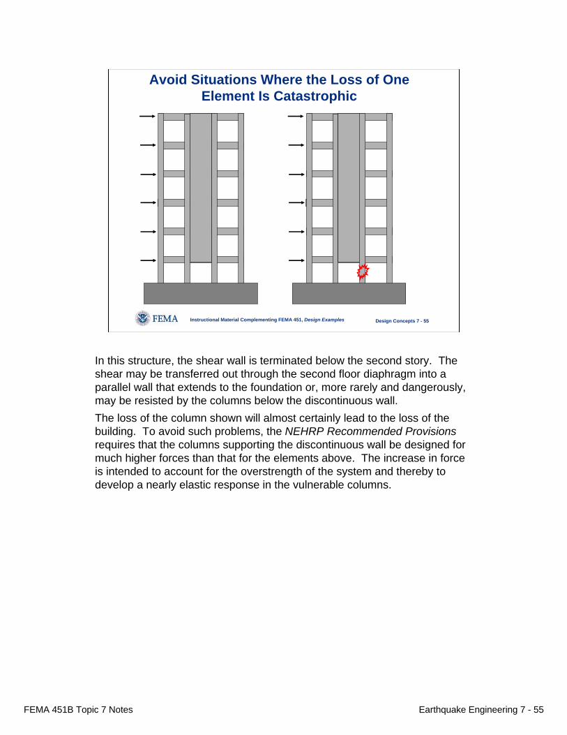
Avoid Situations Where the Loss of OneElement Is Catastrophic
In this structure, the shear wall is terminated below the second story. The shear may be transferred out through the second floor diaphragm into a parallel wall that extends to the foundation or, more rarely and dangerously, may be resisted by the columns below the discontinuous wall.The loss of the column shown will almost certainly lead to the loss of the building. To avoid such problems, the NEHRP Recommended Provisionsrequires that the columns supporting the discontinuous wall be designed for much higher forces than that for the elements above. The increase in force is intended to account for the overstrength of the system and thereby to develop a nearly elastic response in the vulnerable columns.

FEMA 451B Topic 7 Notes Earthquake Engineering 7 - 56
Instructional Material Complementing FEMA 451, Design Examples Design Concepts 7 - 56
Avoid Re-entrant Corners(or Reinforce Accordingly)
Structurally: Improved
Architecturally Dubious
The configuration problem of re-entrant corners is well recognized. If the projecting wings of the building are flexible, the effect shown can lead to very significant damage at the corner.There are basically three solutions to the problem:• Provide a seismic joint (shown)• Provide stiff elements at the projecting ends of the wings to avoid the deformation• Detail the region to accommodate the problem.

FEMA 451B Topic 7 Notes Earthquake Engineering 7 - 57
Instructional Material Complementing FEMA 451, Design Examples Design Concepts 7 - 57
This is a photo of the San Marcos Hotel that partially that collapsed due to the re-entrant corner effect. This happened as a result of the 1925 Santa Barbara earthquake.

FEMA 451B Topic 7 Notes Earthquake Engineering 7 - 58
Instructional Material Complementing FEMA 451, Design Examples Design Concepts 7 - 58
Protect “Nonstructural” Elements
Note that there is tremendous deformation capacity in the columns of the perimeter moment frame of this parking garage. The collapse was actually due to the loss of several interior “nonstructural” gravity columns that were not sufficiently detailed to accommodate the large inelastic displacement demands imposed by the earthquake. The collapse occurred as a result of the 1994 Northridge earthquake.

FEMA 451B Topic 7 Notes Earthquake Engineering 7 - 59
Instructional Material Complementing FEMA 451, Design Examples Design Concepts 7 - 59
1. Develop Concept2. Select Structural System3. Establish Performance Objectives4. Estimate External Seismic Forces5. Estimate Internal Seismic Forces (Linear Analysis)6. Proportion Components7. Evaluate Performance (Linear or Nonlinear Analysis)8. Final Detailing9. Quality Assurance
Steps in the Seismic Design of a Building
The next issue is analysis and is briefly discussed on the next three slides.
FEMA 451B Topic 7 Notes Earthquake Engineering 7 - 60
Instructional Material Complementing FEMA 451, Design Examples Design Concepts 7 - 60
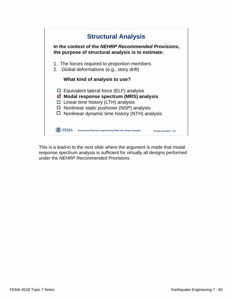
In the context of the NEHRP Recommended Provisions, the purpose of structural analysis is to estimate:
1. The forces required to proportion members2. Global deformations (e.g., story drift)
Structural Analysis
What kind of analysis to use?
Equivalent lateral force (ELF) analysisModal response spectrum (MRS) analysisLinear time history (LTH) analysisNonlinear static pushover (NSP) analysisNonlinear dynamic time history (NTH) analysis
This is a lead-in to the next slide where the argument is made that modal response spectrum analysis is sufficient for virtually all designs performed under the NEHRP Recommended Provisions.

FEMA 451B Topic 7 Notes Earthquake Engineering 7 - 61
Instructional Material Complementing FEMA 451, Design Examples Design Concepts 7 - 61
The analysis must be good enough for design.There should be no expectation that the analysis canpredict actual response (linear or nonlinear)
ELF: Good enough for preliminary design but not final design
MRS: Good enough for design
LTH: Not significantly better than MRS
NSP: The Jury is deliberating
NTH: The best choice for predicting local deformation demands (Note: NTH is not required by NEHRP Recommended Provisions orIBC.)
Structural Analysis
Design engineers should dismiss the notion that the purpose of structural analysis is to predict performance. This can only be done by researchers under very controlled circumstances. The most successful “predictions”usually come after the fact, through systematic variation in parameters until analysis and observed behavior correlate. However, as there are more equations than unknowns in this kind of analysis, it is not always easy tell if the right adjustments have been made.In fact, analysis only needs to be good enough for design. Regarding the NEHRP Recommended Provisions, the ELF method may be good enough for design for very regular structures. For the most part, response spectrum analysis is the best choice. Linear time history analysis is marginally superior to MRS but the slight gain in “accuracy” is not worth the additional effort.There is no reason to perform a nonlinear analysis for systems designed under NEHRP Recommended Provisions unless one wants to evaluate the system as if it were an existing building. Due to the limitations of nonlinear static pushover analysis, the best choice for nonlinear analysis is time-history analysis. As the old hand said when looking at a younger engineer’s computer output: That looks very precise, but how accurate is it?

FEMA 451B Topic 7 Notes Earthquake Engineering 7 - 62
Instructional Material Complementing FEMA 451, Design Examples Design Concepts 7 - 62
Structural Analysis: Relative Level of Effort
0
1
2
3
4
5
6
7
ELF MRS LTH NSP NTHANALYSIS METHOD
REL
ATI
VE L
EVEL
OF
EFFO
RT
These are estimates of the amount of effort required to perform an analysis. The main reason for the increase in time for the LTH method is the time to identify and scale the ground motions and to post-process the results. The mathematical models for the ELF, MRS, and NSP are basically identical.The increase in time for the nonlinear approaches represents the effort required to develop the inelastic response model for the structure. The increase in time required for the time history analysis (might actually go up to 8) is for modeling hysteretic behavior (not required for NSP) and for setting up and scaling ground motion histories and post-processing results.It is felt by many engineers that the limitations of pushover analysis warrant the use of time history analysis in spite of the additional cost.

FEMA 451B Topic 7 Notes Earthquake Engineering 7 - 63
Instructional Material Complementing FEMA 451, Design Examples Design Concepts 7 - 63
Seismic Design (and Analysis)Is as Much an Artas It Is a Science
Experience matters.