conceptual and technical challenges in defining flood ... ryan .pdf · conceptual and technical...
TRANSCRIPT
2015 Floodplain Management Association National Conference 1
CONCEPTUAL AND TECHNICAL CHALLENGES IN DEFINING FLOOD PLANNING AREAS IN URBAN CATCHMENTS
C Ryan1, D Tetley2, C Kinsey3 1 & 2 Catchment Simulation Solutions, NSW 3 Co-ordinator Stormwater and Structural Design, Campbelltown City Council, NSW
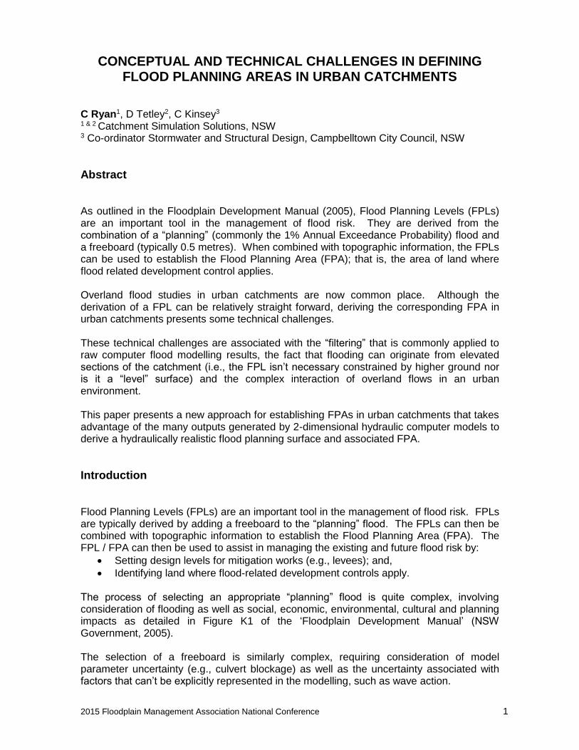
Abstract As outlined in the Floodplain Development Manual (2005), Flood Planning Levels (FPLs) are an important tool in the management of flood risk. They are derived from the combination of a “planning” (commonly the 1% Annual Exceedance Probability) flood and a freeboard (typically 0.5 metres). When combined with topographic information, the FPLs can be used to establish the Flood Planning Area (FPA); that is, the area of land where flood related development control applies. Overland flood studies in urban catchments are now common place. Although the derivation of a FPL can be relatively straight forward, deriving the corresponding FPA in urban catchments presents some technical challenges. These technical challenges are associated with the “filtering” that is commonly applied to raw computer flood modelling results, the fact that flooding can originate from elevated sections of the catchment (i.e., the FPL isn’t necessary constrained by higher ground nor is it a “level” surface) and the complex interaction of overland flows in an urban environment. This paper presents a new approach for establishing FPAs in urban catchments that takes advantage of the many outputs generated by 2-dimensional hydraulic computer models to derive a hydraulically realistic flood planning surface and associated FPA.
Introduction Flood Planning Levels (FPLs) are an important tool in the management of flood risk. FPLs are typically derived by adding a freeboard to the “planning” flood. The FPLs can then be combined with topographic information to establish the Flood Planning Area (FPA). The FPL / FPA can then be used to assist in managing the existing and future flood risk by:
Setting design levels for mitigation works (e.g., levees); and,
Identifying land where flood-related development controls apply. The process of selecting an appropriate “planning” flood is quite complex, involving consideration of flooding as well as social, economic, environmental, cultural and planning impacts as detailed in Figure K1 of the ‘Floodplain Development Manual’ (NSW Government, 2005). The selection of a freeboard is similarly complex, requiring consideration of model parameter uncertainty (e.g., culvert blockage) as well as the uncertainty associated with factors that can’t be explicitly represented in the modelling, such as wave action.
2015 Floodplain Management Association National Conference 2
Consideration of all of the components that influence the selection of a planning flood and freeboard(s) is typically not considered until the Floodplain Risk Management Study. However, in NSW, FPAs are commonly requested by Councils during the flood study phase of the floodplain risk management process. As all of the required factors listed above are typically not considered during the flood study, the selection of a planning flood and freeboard is often simplified with the planning flood typically defined as the 1% AEP event with a freeboard of 0.5 metres (although 0.3 metres is also used in “built up” catchments or where flood depths are minor). Councils may also choose to apply differing freeboards for different parts of the catchment. Over the last decade, overland flood studies have become more prevalent as Council’s look to manage flooding across “built up” areas. Flooding in an urban catchment can be considerably more complex relative to traditional “main stream” flooding. This presents challenges to modellers trying to define flood behaviour in such catchments and also increases the complexity associated with defining a FPA in an urban setting. Some of the complexities and challenges associated with defining a FPA in an urban area are discussed below.
Traditional Approach for Defining Flood Planning Area Traditionally, FPAs have been prepared by:
1. Elevating the planning flood by the required freeboard to define the FPL for a particular location (refer Figure 1 overleaf)
2. The FPL is then extended laterally into higher ground to form the FPA (refer Figure 2 overleaf).
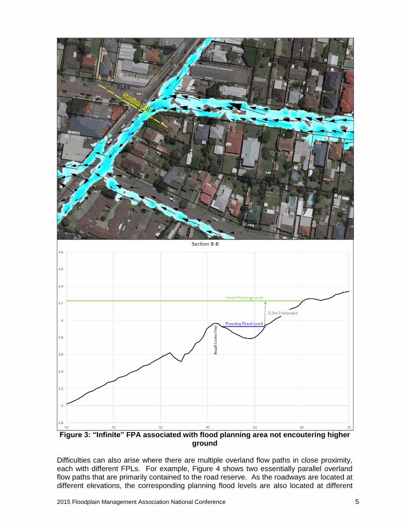
This approach has traditionally been applied to creeks / river channels or lakes where the floodwater is sourced from areas located below the surrounding land (i.e., “main stream” flooding). Consequently, the FPL will typically always be confined by “higher ground” allowing a well-defined and unambiguous FPA to be established. Limitations of Traditional Approach for Defining FPA in Urban Areas Overland flooding differs from traditional main stream flooding. As a result, the traditional approach for defining FPA has limitations and can be difficult to manage in an urban catchment. Firstly, overland flooding originates from areas that can be located above the surrounding land. As illustrated in Figure 3 (page 5), if the planning flood is elevated by the freeboard and extended in such situations, the FPL can be overestimated as the resulting flood planning surface is not always constrained by higher ground in the downstream direction. Therefore, the FPA can be significantly overestimated and the FPL can be far too high.

2015 Floodplain Management Association National Conference 3
Figure 1: Traditional approach to defining the flood planning area first involves
elevating the planning flood level by the freeboard. This defines the flood planning level

2015 Floodplain Management Association National Conference 4
Figure 2: The flood planning area is then created by extending the flood planning
level laterally into higher ground
2015 Floodplain Management Association National Conference 5
Figure 3: “Infinite” FPA associated with flood planning area not encoutering higher
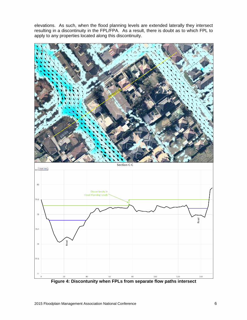
ground Difficulties can also arise where there are multiple overland flow paths in close proximity, each with different FPLs. For example, Figure 4 shows two essentially parallel overland flow paths that are primarily contained to the road reserve. As the roadways are located at different elevations, the corresponding planning flood levels are also located at different
2015 Floodplain Management Association National Conference 6
elevations. As such, when the flood planning levels are extended laterally they intersect resulting in a discontinuity in the FPL/FPA. As a result, there is doubt as to which FPL to apply to any properties located along this discontinuity.
Figure 4: Discontunity when FPLs from separate flow paths intersect

2015 Floodplain Management Association National Conference 7
The definition of FPL/FPAs in urban areas is further complicated by the “filtering” that is often performed on the raw computer modelling results. This is particularly the case for “direct rainfall” models where the entire catchment can be “wet” and there is a need to distinguish between areas of negligible and more significant overland flooding. Although this filtering process can improve the presentation of the overland flood modelling results, it often results in a discontinuous flood surface (refer Figure 5 showing lots of ‘puddles’). Consequently, the “filtering” process removes information describing how the planning flood surface (and consequently FPL surface) varies between these areas of significant overland flooding.
Figure 5: “Filtering” of computer model results can reduce the amount of
information used to form the basis of the FPA calculations Overall, the definition of a FPA in an urban environment is made difficult by the complex interaction between multiple flow paths and the filtering of flood results surfaces. It is apparent that these complexities mean that a “straight” lateral extension of the FPL will not always produce a satisfactory flood planning area. This is most evident in areas where the FPL does not encounter elevated terrain. Therefore, it is suggested that an improved approach for deriving FPLs in such instances is needed to supplement the traditional “straight line” extension approach.
Other Approaches in the Literature The problems with defining the FPA in urban environments has been noted by several consultants. A range of approaches has been trialled to overcome the problems, including:
Pittwater Overland Flow Mapping and Flood Study (Schwecke 2013) o After investigating applying a 0.5m vertical freeboard to the ‘major’ 1% AEP
overland flow paths, it was decided that a 5m horizontal freeboard was preferred owing to the steep / incised topography across the study area. It was noted that both methods underperformed in certain circumstances.

2015 Floodplain Management Association National Conference 8
Hazelbrook and Woodford Catchments Mainstream and Overland Flow Flood Study (MHL, 2013)
o To compensate for the issues associated with application and lateral extension of a freeboard, it was decided to adopt the results of one of the sensitivity analysis design floods (1% AEP + 30% rainfall intensity increase) to define the FPA. Within this FPA, the FPL was defined as the maximum of the 1% AEP + 30% rainfall intensity increase flood or the 1% AEP flood plus a 0.3m. Although this provided a relatively straight forward approach for defining the FPA, it can cause issues at the edge of the FPA where the FPL does not intersect the ground surface (due to the 1% AEP + 0.3m scenario being used to define the FPL while the 1% AEP +30% is used to define the FPA).
Draft Review of Marrickville Council’s Property Flood Tagging (WMAwater 2013)
o This report also notes the difficulties associated with application and extension of a vertical freeboard. The report proposed a combined method using a 0.5m vertical freeboard and extension into higher ground for main stream areas. No vertical freeboard was applied outside main stream flooding areas. All properties that are predicted to be inundated by more than 150mm or more than 10% of the lot area were tagged as ‘flood impacted’. Furthermore, an LGA wide rule was proposed that would require all habitable floor levels to be at least 300mm above the surrounding ground. This approach has the advantage of avoiding the need for creating a FPA polygon in overland flooding areas. Rather, a global building freeboard is applied throughout the LGA and lots that may be susceptible to more significant flooding are tagged for potential application of further development controls. This approach recognises that the traditional approach to FPA and FPL are not necessarily appropriate in overland flooding areas. Furthermore, the “300mm rule” indirectly recognises that overland flooding can happen almost anywhere given certain combination of rainfall intensity, blockages, topographic changes and other unknowns. However, this approach does require some specialist GIS knowledge to apply the appropriate criteria and may be more difficult to present / interpret on a map relative to a FPA polygon.
All the methods presented above have their own advantages and disadvantages. They may suit applications in their respective catchments or a range of topographic characteristics that may be unique to these catchments. For our work with Campbelltown Council, Council requested that a FPA be prepared for inclusion in their GIS that was consistent with the traditional lateral extension approach. As such, CSS began a research project into how best to achieve this. The following sections describe the method developed.
Modified Approach for Defining FPA in Overland Flood Areas As discussed, the traditional approach for deriving FPL estimates does not always produce satisfactory results in areas where the terrain “drops away”, where filtering damages overland flow path connectivity and when there is interaction between multiple overland

2015 Floodplain Management Association National Conference 9
flow paths. Therefore, an alternate approach for deriving FPLs in urban catchments was developed. In effect, the addition of a freeboard onto the planning flood (which may or may not be filtered) creates a new flood surface. Therefore, it was felt that an improved approach to the FPL / FPA estimation process could be achieved by making use of the “library” of flood surfaces that are generated during the design flood modelling stage of a typical flood study. Our method consisted of three main steps.
1. Derivation of flow path alignments from the TUFLOW model results to determine how FPL “puddles” would be linked longitudinally and, potentially, laterally.
2. Interpolation along each flow paths to define how the flood planning surface varies longitudinally between ‘puddles’ and/or adjoining flow paths. The interpolation was informed by the aforementioned library of flood surfaces.
3. Lateral extension of the resulting flood surface into higher ground including:
Retain existing “straight line” extension in instances where the “stretched” FPL encounters higher ground.
Apply a varying FPL where higher terrain is not encountered and / or where interaction between adjoining flow paths is experienced. The FPL is informed by the library of flood surfaces, thereby reflecting the hydraulic characteristics of the area.
Each step in this method is outlined in the following sections. Creating a Flow Path Map from TUFLOW Results As discussed, a “filter” is often applied to raw flood model results in urban catchments to distinguish between areas of negligible and more significant overland flooding. Although the filter criteria (if any) will likely vary from Council to Council, the net result is that a discontinuous flood surface is frequently used to initiate the FPA / FPL calculations. For example, Campbelltown City Council has resolved to “filter” the raw modelling results so that only 1% AEP floodway, flood storage and high hazard areas are included in the flood planning area calculations. Therefore, the first step in the revised interpolation approach involved the development of vector flow paths to serve as the basis for longitudinal interpolation of the FPL between ‘puddles’. The goal here is to try and better represent how each of the filtered puddles would be hydraulically linked enabling a more realistic description of FPLs between puddles. Unfortunately, hydraulic modelling software (e.g., TUFLOW) does not routinely generate vector flow paths. As a result, a utility was developed to map vector flow paths from source points based on a velocity angle (e.g.,TUFLOW VA) grid. The upstream pixels of the filtered modelling result “puddles” were used to define the source points for the flow path mapping algorithm and the PMF VA grid was used to describe the direction that each flow path would follow between the puddles. This process aims to determine how water would “spill” from one FPL puddle to another FPL puddle. As shown in Figure 6, this approach provides a detailed description of how water moves across the study area. In doing so, it provides a useful basis for describing what areas would get “wet” if the FPL puddles spilled and, therefore, what areas should be included in the FPL and FPA calculations.

2015 Floodplain Management Association National Conference 10
The flow paths generated for a small sample area are also shown in Figures 6 and 7. As shown, the flow paths portray both convergence and divergence of the flood waters. In particular, they show how flow paths move between puddle areas and how adjoining flow paths potentially interact.
Figure 6: Broad scale view of flow path alignments showing complex flow patterns
Figure 7: Detailed view showing flow path alignments (dashed lines) in the vicinity
of buildings. “Source” flood planning level puddles are also shown.
Flood Planning Level (mAHD)
2015 Floodplain Management Association National Conference 11
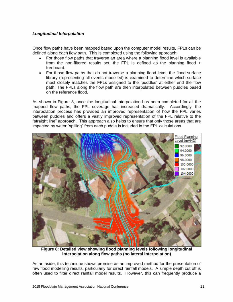
Longitudinal Interpolation Once flow paths have been mapped based upon the computer model results, FPLs can be defined along each flow path. This is completed using the following approach:
For those flow paths that traverse an area where a planning flood level is available from the non-filtered results set, the FPL is defined as the planning flood + freeboard.
For those flow paths that do not traverse a planning flood level, the flood surface library (representing all events modelled) is examined to determine which surface most closely matches the FPLs assigned to the ‘puddles’ at either end the flow path. The FPLs along the flow path are then interpolated between puddles based on the reference flood.
As shown in Figure 8, once the longitudinal interpolation has been completed for all the mapped flow paths, the FPL coverage has increased dramatically. Accordingly, the interpolation process has provided an improved representation of how the FPL varies between puddles and offers a vastly improved representation of the FPL relative to the “straight line” approach. This approach also helps to ensure that only those areas that are impacted by water “spilling” from each puddle is included in the FPL calculations.
Figure 8: Detailed view showing flood planning levels following longitudinal
interpolation along flow paths (no lateral interpolation) As an aside, this technique shows promise as an improved method for the presentation of raw flood modelling results, particularly for direct rainfall models. A simple depth cut off is often used to filter direct rainfall model results. However, this can frequently produce a
Flood Planning Level (mAHD)

2015 Floodplain Management Association National Conference 12
series of disconnected puddles that are, in reality, linked by areas of shallower flow to form continuous flow paths. Applying the vector flow path approach described above between the disconnected puddles and reinstating the raw modelling results for those areas underlying each flow paths produces a hydraulically realistic continuous flow path. Lateral Extension Lateral extension of the FPL into neighbouring areas is achieved by a ray based algorithm designed to find the closest defined FPL pixels and then interpolate the FPL for the target area based on inverse distance weighting. However, the algorithm also seeks to exclude nearby FPLs that are separated by higher ground by analysis of the underlying DEM. As a result, the interpolation approach aims to provide “straight line” interpolation where the extended FPL encounters higher ground and a gradually varied FPL where the extended FPL encounters an adjoining FPL. The inverse distance weighting approach also takes advantage of the flood surface library to ensure that a hydraulically realistic surface is provided. Following lateral extension of the FPL, the FPA can be defined. This is shown in Figure 9 for the sample area.
Figure 9: Final FPL / FPA following lateral extension into higher ground
The method documented in this paper produces superior results to other forms of FPL extension that the authors are aware of. Specifically, flat line extension techniques typically applied in main stream flooding situations will produce very unreliable results in urban areas.
Flood Planning Level (mAHD)

2015 Floodplain Management Association National Conference 13
The discussed method is not perfect and problems may still arise. Often the planning flood plus freeboard is well above the PMF which can make interpolation and extension more difficult as there are no similar hydraulic modelling results to help guide the interpolated surfaces. Manual review by flood engineers is still recommended to ensure the method is producing acceptable results. The author’s also suggest that further research is needed into the suitability of freeboards in general for overland flow paths and the potential for use of alternative methods such as confidence interval based planning levels.
Conclusion This paper has documented an approach that attempts to solve the well-known issues associated with definition of FPLs and FPAs in urban catchments. The method involved extracting flow path alignments from hydraulic model results, longitudinal interpolation along these flow paths informed by a library of modelled flood surfaces, and extension of the resulting FPL into neighbouring terrain / flow paths. While this method is not perfect, it does generate a FPL surface that is more representative of the actual hydraulic modelling results than the other methods reviewed and trialled. Further research and development of the discussed concepts and algorithms should help to improve the results and reduce the need to manual intervention.
References
1. NSW Government. (2005). Floodplain Development Manual: the Management of Flood Liable Land. ISBN: 0 7347 5476 0.
2. Schwecke (2012), Draft Pittwater 2012 Overland Flow Flood Study and Mapping 3. Manly Hydralics Laboratory (2013), Hazelbrook and Woodford Catchments
Mainstream and Overland Flow Flood Study 4. WMAwater (2013), • Draft Review of Marrickville Council’s Property Flood
Tagging