conceptual design aspects of three general sub-classes of ... · multi-rotor configurations:...
TRANSCRIPT

Conceptual Design Aspects of Three General Sub-Classes of Multi-Rotor Configurations: Distributed, Modular, and
Heterogeneous
Larry A. Young NASA Ames Research Center, Moffett Field, CA 94035
Abstract
Quadcopters and other multi-rotor configurations are poised to make a substantial contribution to commercial and public service aviation. Small multi-rotor configurations already see almost ubiquitous use as radio-controlled toys and hobbyist platforms. In particular, their use as “flying cameras” has seen rapid adoption by the public. But their greatest contribution to our society may likely be seen in public service missions/applications. Their potential utility for supporting emergency response missions is discussed in some detail. The multi-rotor design space is then explored from a high-level perspective – with the emphasis on distributed, modular, and heterogeneous multi-rotor systems. Following this design space examination, a number of specific, detailed technical issues related multi-rotor conceptual design and sizing are also considered.
Nomenclature
A = Disk area, πR2, m2 b/R = Uniform horizontal spacing, with respect to rotor radius, between adjacent rotors in a
distributed (linear array) multi-rotor configuration CP = Power coefficient CT = Thrust coefficient DL = Rotor disk loading, N/m2 L/De = Effective lift-to-drag ratio P = Rotor power, W R = Radius of an individual rotor, m r/R = (Mean) rotor radial location, with respect to rotor radius, from center of multi-rotor
circular pattern T = Rotor thrust, N σ = Blade solidity
Presentation at the Sixth AHS International Specialists Meeting on Unmanned Rotorcraft Systems, Scottsdale, AZ, January 20-‐22, 2015.

Introduction
Over the last few years, considerable interest has developed in multi-rotor configurations for a number of applications. For example, radio-controlled and smart-phone/tablet-controlled quadcopters have become very popular hobbyist and academic research platforms. Quadcopters and other multi-rotor configurations are also finding rapidly expanding application as “flying cameras” for personal and media usage; for example, quadcopters were employed during the 2014 Winter Olympics taking aerial video images of skiers and snowboarders competing. Quadcopters are also currently being evaluated for possible military application, particularly surveillance/situational-awareness in urban environments. More recently, multi-rotor configurations are being seriously pursued as possible commercial small-package aerial delivery systems by the likes of Amazon.com and Google. Finally, in addition to small VTOL platforms – typically well under 25 kilograms – larger, manned multi-rotor configurations are being considered for VTOL general aviation applications. In many cases, multi-rotor configurations are opening up new aviation applications and markets, rather than merely competing for traditional manned helicopter markets/applications. It is anticipated that when FAA regulations are finally released for small commercial uninhabited aerial vehicle (UAV) operations that an even more expansive growth than what has been seen to date will occur for VTOL multi-rotor UAVs.
Small rotary-wing UAVs, micro-rotorcraft, and multi-rotor configurations have been investigated for over a decade within NASA (e.g. Refs. 1-6). The key advantages of quadcopters – and other multi-rotor systems – are their operational simplicity and low cost. However, multi-rotor configurations suffer from a number of issues, not the least of which is their generally low rotor/vehicle aerodynamic efficiencies both in hover and loitering flight and in cruise. Additionally, current experience with these vehicles is limited to very small aircraft, typically less than 2 kilograms in mass; it is unclear how scalable, even to the modest 25 kilogram size likely to be required for small-package delivery applications, such vehicles will be. It is, therefore, important to consider means by which the performance and scalability of multi-rotor vehicles can be improved above that of the current generation of vehicles (i.e. <2kg quadcopters, hexacopters, and octocopters).
In pursuit of this goal, three new sub-classes of multi-rotor vehicles will be investigated from a conceptual design perspective. These sub-classes are: distributed, modular, and heterogeneous multi-rotor configurations. The definition of each sub-class, for the purposes of this paper, now follows. A distributed multi-rotor configuration is: a vehicle that has a number of rotors/propellers greater than eight (i.e. outside of current experience base of quad-, hexa-, and octo-rotors) that are arranged in one or more 2-D/planar arrays with either uniform or nonuniform spatial distribution (of the rotors/propellers) in the arrays. It is further assumed that distributed multi-rotor vehicles have static (unchanging) configurations/geometries. A modular multi-rotor configuration is a: a vehicle (or more correctly a suite of vehicles) that is not static in configuration but in fact can assembled, disassembled, and reassembled (between flights/missions) into different multi-rotor arrangements (in a tinkertoy- or Lego-like manner). A heterogeneous multi-rotor configuration is: a multi-rotor vehicle employing two or more different types, sizes, and arrangements of rotors/propellers where each type of rotor performs some unique function during the flight/mission. It is noteworthy that almost all multi-rotor systems to-date are homogeneous (i.e. all rotors are the same in both size and geometry) and to a lesser degree have (but still the norm) symmetrical rotor/propeller arrays, or arrangements, about the vehicle lateral and longitudinal axes.
Figures 1 and 2 are examples of conventional multi-rotor configurations – in this particular case quadcopters or aka quad-rotors.

Figure 1 – A hover CFD result for a typical quadcopter configuration
Figure 2 – The relative size difference of a 1kg verus 25kg quadcopter (keeping the disk loading constant)
An example of a distributed multi-rotor configuration (with an elliptical cross-section payload pod over the rotor arrays) is shown in Fig. 3. (Note that such a distributed multi-rotor configuration could be readily extended to a modular configuration, if need be. The multi-rotor vehicle of Fig. 3 could conceptually be realized by a LegoTM-like stacking of tractor-and-pusher-propeller quadcopters (ones that could already now, in the small RC vehicle sense, be bought from hobbyist aircraft manufacturers and crafted into a notional assembly similar to Fig. 3.)

Figure 3 – A distributed multi-rotor configuration with over fifty rotors/propellers; a representative hover computational fluid dynamic (CFD) result (velocity-magnitude
isosurfaces delineating the rotor wake boundaries)
An example of a modular multi-rotor configuration is given in Fig. 4a-c; in this series of figures, coaxial-rotor modules elements could be flown as free-flying vehicles, or, alternatively, with introduction of support-structures, could be assembled into quadrotor or octocopter configurations as need be for on-demand vehicle scalability to meet mission requirements. (Such modularity could even go beyond the octocopter configuration shown.)
(a)

(b)
(c)
Figure 4 – Modular multi-rotor configurations: e.g. (a) coaxial configurations assembled into (b) quadrotor configurations, which can be further assembled into (c)
octocopter, or higher, configurations
There can be ideally two different types of modular rotorcraft elements: matched and unmatched. Matched elements have their anti-torque provision built into them. Unmatched do not have full anti-torque capability inherently provided into them; anti-torque is only provided when unmatched elements, or other add-on components, are attached/assembled to each other. A matched element approach – with coaxial-rotor elements – is shown in Fig. 4. An unmatched element approach – where only single-rotor elements, without anti-torque features such as vanes or tail-rotors, are employed – can be found in Ref. 7 (such single-rotor elements have to be, of course, added/assembled to an equal number of counter-rotating single-rotor elements). Finally, modular rotorcraft could also use a combination of matched and unmatched elements in their overall configuration.
An example of a heterogeneous multi-rotor configuration is given in Fig. 5. Many more heterogeneous configurations are possible; Fig. 5 is one of the simplest heterogeneous multi-rotor configurations. It should be noted that a similar configuration was studied in Ref. 21.

Figure 5 – Hover CFD results for a representative heterogeneous multi-rotor configuration: two lifting rotors and three directional-control thruster rotors
There are some very interesting flight control questions related to many of these alternative vehicle configurations. One of the more interesting set of questions has to do with flight control of quadcopters, quadrotors, and multi-rotor configurations in general. Conventional helicopters and tiltrotor aircraft have complex mechanical control systems to provide variable collective and variable cyclic pitch control (varying nominally on a once-per-revolution basis for primary flight control). For very small radio-controlled hobbyist-class quadcopters/quadrotors, etc., simple flight control schemes are employed, the chief approach being speed control of fixed-pitch (constant collective and no cyclic) propellers. Though this simple speed control approach has led, in part, to the widespread success of these small vehicles, it is unlikely to scale well to larger vehicles. And, yet, it may well be that a hybrid flight control – wherein individual rotor speed control could be matched/integrated with variable collective/cyclic control -- might be the best solution for Hopper-class quad- or multi-rotor vehicles. Another interesting set of flight control issues arises when one considers structural flexibility of rotor support arms/braces (and/or “stacked” rotors and supports/braces) for multi-rotor and modular rotorcraft configurations. An extreme example of this would be if the flying platform of Fig. 3 were allowed to have such a large degree of structural flexibility amongst it modular elements that it instead could be considered an elastic “carpet” of rotors rather than a near-rigid structural assembly. Such flight control areas of investigation as hybrid rotor control for multi-rotors and structural flexibility implications of large modular rotorcraft assemblies are largely unexplored to date.

Defining the Global Design Space
Multi-rotor configurations represent a potentially rich design space that has only just begun to be explored. The first step to defining and exploring this design space begins with the identification and discussion of the three sub-classes – distributed, modular, and heterogeneous systems – of multi-rotor configurations brought forth in the introductory comments of this paper. To aid in this preliminary effort of exploring the multi-rotor design space, a public service application domain and a number of potential missions, or perhaps more correctly use cases, will next be discussed.
An Application Domain and Suite of Missions: Emergency Response
Rather auspiciously, NASA has crafted two “Big Questions” for FY15 for its aeronautics research programs. These Big Questions are intended to focus technical efforts into technically relevant research for societal benefit. One of the two Big Questions is particularly appropriate for the two NASA research projects -- the Vertical Lift Hybrid-electric Autonomy (VLHA) and Revolutionary Vertical Lift Technology (RVLT) projects -- most applicable to vertical flight: How can one demonstrate the feasibility of providing urgent medical transportation from the wilderness of Alaska to the Mayo Clinic without human interaction? As a partial hypothetical response to this posed question, the following storyboard scenario is offered:
Joe gets into a hunting accident while in the Alaskan wilds. Cell phone call from Joe's hunting partner contacts Alaskan state troopers. A small UAV locates Joe and his partner, identifies nearest cleared area and stays overhead on station for coordination and situational awareness. A 2000 lb class autonomously piloted VTOL rescue/medical platform is launched from Fairbanks University of Alaska medical center. Medical rescue staff are onboard but not piloting the vehicle. The VTOL vehicle rescues Joe and hunting partner. Emergency medical treatment is initiated in transit. Telemedicine resources are available to provide sophisticated trauma treatment. Joe goes suffers a major seizure mid-flight partly as a consequence of blood loss and hypothermia. EKG equipment onboard the VTOL indicates a major compromise to proper brain functioning. The VTOL is redirected to Fairbanks airport while a specialized autonomous critical care medical transport tiltrotor is launched from Juneau to Fairbanks. Initial flight plans call from the tiltrotor to return to Juneau from Fairbanks after transferring Joe. A network of medical experts and expert systems have determined that Joe's condition is critical and that the only medical center that has the specialized care protocol for Joe is the Mayo Clinic in Minnesota. The autonomous medical transport tiltrotor is authorized to fly from Fairbanks through Canadian airspace to Minnesota. US/Canadian governmental agencies coordinate an autonomous inflight refueling of the emergency transport tiltrotor midway through its flight. Such military/civilian refueling has become near-standard procedure for enabling time critical missions. Joe makes it to Mayo Clinic in the most expeditious manner possible.
The first half of the above noted storyboard scenario is broadly applicable to the VLHA project and the second half is applicable to the RVLT project.
Missions A-C are emergency response missions that could potentially be satisfied by multi-rotor UAVs. These missions are a subset of the general classes of disaster relief and emergency

responses missions for autonomous vertical lift aerial vehicles identified in Ref. 3. Missions A-C are also consistent with conceptual design test cases being developed within the context of NASA’s Vertical Lift Hybrid-electric Autonomy (VLHA) project. For informal descriptive purposes, vehicles responding to such notional disaster relief and emergency response missions are referred to herein this paper as SPRITES (Smart Precise Rotorcraft Interconnected Emergency Services); Fig. 6a-b. Why SPRITES as an informal name/acronym for such vehicles? To summarize from various dictionaries/online sources: Sprites (red and blue) are high-altitude atmospheric electrical phenomena (thereby providing a tie-in with electric-propulsion and NASA); Sprites from folktales are winged, magical beings that imbued with various levels of (usually mischievous) intelligence (thus providing a tie-in with UAVs and autonomous/intelligent systems); “sprite” and “spritely” also imply speed and agility, key attributes for emergency response missions.
Figure 7a-c illustrates a very level description of emergency response missions/use cases that are representative of the applications to be studied in this and future work of the VLHA project.
(a)
(b)
Figure 6 – SPRITES: (a) notional heterogeneous multi-rotor configuration and its partial namesake upper atmosphere electrical phenomena and (b) computational result for the
vehicle configuration

(A)
(B)
(C)
Figure 7 – Emergency Response Notional Missions: (A) Search and Rescue Aerial Survey; (B) Aerial Telecom/Data Relay; and (C) Emergency Equipment Aerial Lift

Some Computational/Analytical Results in Exploring the Design Space
Multi-rotor configurations present novel challenges with respect to their aerodynamic performance and other design characteristics. Some initial computational and analytical investigations are summarized below for the three general sub-classes of multi-rotor configurations discussed in this paper as well as some cross-cutting design considerations – specifically weight estimation and low Reynolds number rotor operation – that apply for all multi-rotor and/or small autonomous VTOL UAVs.
Heterogeneous Multi-Rotor Configurations
The design space that embodies heterogeneous multi-rotor configuration is extremely large. To fully explore the spectrum of the possible heterogeneous configurations may justify using ultimately genetic or evolutionary algorithm design and optimization methods. The preliminary investigation documented in this paper can only be considered a very limited look at novel designs. Figure 8 is one such novel heterogeneous multi-rotor configuration: two large, low disk loading rotors to efficiently provide most of the vehicle’s lift and four smaller, high disk loading “thruster” rotors to provide quadcopter static trim flight control via simple speed control. Figure 8 immediately illustrates one striking feature of multi-rotor wakes in hover in general, heterogeneous rotor wakes in particular, in that there are complex mid- to far-wake interactions that can only be predicted by sophisticated rotor wake analysis software, in this case unsteady Navier-Stokes computational fluid dynamics solver; Ref. 8. In Fig. 8, the thruster rotor wakes are ultimately entrained into the primary wake region of the two coaxial lifting rotors.
Figure 8 – Unique Rotor Wake Interactions in the Far Wake for Heterogeneous Multi-Rotor Configurations
Though there is value in trying to maximize the lift carried by large, low disk load rotors and reserve the smaller, higher disk load thrusters primarily for trimming the vehicle, there is a counterpoint to the efforts to try improving the aggregate rotor hover performance. To support the thrusters such that they are at global radial station outside the rotor disks of the lifting rotors requires more support/cross-arm structure – and, therefore, weight – as well as an increase in hover download resulting from the increased planform area of such structure within the rotor wakes of the rotors. Figure 9 is an initial CFD prediction of the surface pressure of a simple cross-arm structure for a heterogeneous multi-rotor configuration. The CFD predicted hover

download for this configuration is 1.65% of the vehicle thrust. Also seen in the figure is the modification of the rotor wakes (see compared to the previous figure which does not have the cross-arms and other fixed-frame structure) as a consequence of the presence of the cross-arms.
Figure 9 – Optimizing for download in hover (surface pressures on vehicle in hover, shown above) and minimizing parasite drag in forward-flight
Figure 10a-e presents the five heterogeneous multi-rotor configurations studied to gain an initial assessment of the influence of the relative lift share provided by the thrusters (four) versus the lifting rotors (two in a coaxial arrangement). The primary purpose of the thrusters to provide for vehicle trim; the lifting rotors are to provide the majority of the vehicle lift. The ratio of thruster disk loading to lifting rotor disk loading is fixed at DLT/DLLR = 5.3 for all five configurations. The tip speeds, collective pitch angles, and disk loading of each type of rotor are maintained; the radial location of the thrusters is also maintained.
(a) (b)
(c) (d)
(e)
Figure 10 – Heterogeneous Multi-Rotor Configurations examined as a part of Lift Share Sweep between Thrusters and Lifting Rotors: (a) 10 percent of vehicle lift carried by
thrusters; (b) 20 percent; (c) 30 percent; (d) 42 percent; (e) 50 percent

Figure 11 summarizes some of the predicted results of the Fig. 10 configurations. Not unexpectedly, as the lift share of the higher disk load thrusters is reduced the efficiency, as represented by the power loading (P/T) of the overall vehicle, increases, i.e. P/T gets smaller, as a consequence of more of the lift in hover being carried by the larger, lower disk load coaxial lifting rotors.
Figure 11 – Influence of Lift Share on Heterogeneous Multi-Rotor Configuration Hover Power Loading Trend
Modular Multi-Rotor Configurations
This investigation leverages off of the multi-rotor configuration shown earlier in Fig. 3. A number of interesting questions as to “circle packing” of prescribed areas can be posed by this type of multi-rotor configuration. The design challenge for such vehicles is compounded in that more than one horizontal plane could be used for the rotor arrays. CFD predictions were made for a configuration build-up of a modular multi-rotor system. Figure 12 and illustrates several incremental CFD hover cases of increasing rotor count that were performed. These cases ranged from four to thirty-six rotors, in delta counts of four (to reflect the addition of quadcopter-like “building blocks” for the modular vehicle).
7"
7.5"
8"
8.5"
9"
9.5"
10"
0" 0.6"
Power&Loa
ding,&P
/T,&W
a1s/N&
0.1" 0.2" 0.3" 0.4" 0.5"
Li4&Share&of&Thrusters&against&Total&&Li4&Required&

Figure 12 – Modular Configurations Comprised of “Stacked” Quadrotor “Building Blocks” (from four to thirty-six rotors)
Figure 13 – Rotor Wake Predictions of the Modular Configurations
Figure 14 shows the power-loading trend as a function of the number of rotors comprising the modular multi-rotor configuration. Note that power loading levels for Fig. 14 are much higher than that of the other multi-rotor CFD hover performance trends reported in this paper. This is because, for just this singular case, the rotors analyzed for the modular multi-rotor configuration discussion are much larger than the rotors, and multi-rotor configurations (heterogeneous and distributed), studied in the rest of the paper.
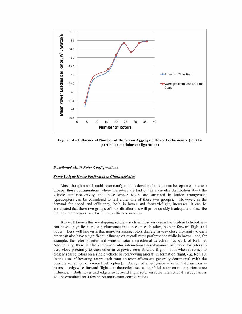
Figure 14 – Influence of Number of Rotors on Aggregate Hover Performance (for this particular modular configuration)
Distributed Multi-Rotor Configurations
Some Unique Hover Performance Characteristics
Most, though not all, multi-rotor configurations developed to-date can be separated into two groups: those configurations where the rotors are laid out in a circular distribution about the vehicle center-of-gravity and those whose rotors are arranged in lattice arrangement (quadcopters can be considered to fall either one of these two groups). However, as the demand for speed and efficiency, both in hover and forward-flight, increases, it can be anticipated that these two groups of rotor distributions will prove quickly inadequate to describe the required design space for future multi-rotor vehicles.
It is well known that overlapping rotors – such as those on coaxial or tandem helicopters – can have a significant rotor performance influence on each other, both in forward-flight and hover. Less well known is that non-overlapping rotors that are in very close proximity to each other can also have a significant influence on overall rotor performance while in hover – see, for example, the rotor-on-rotor and wing-on-rotor interactional aerodynamics work of Ref. 9. Additionally, there is also a rotor-on-rotor interactional aerodynamics influence for rotors in very close proximity to each other in edgewise rotor forward-flight – both when it comes to closely spaced rotors on a single vehicle or rotary-wing aircraft in formation flight, e.g. Ref. 10. In the case of hovering rotors such rotor-on-rotor effects are generally detrimental (with the possible exception of coaxial helicopters). Arrays of side-by-side -- or in V-formations -- rotors in edgewise forward-flight can theoretical see a beneficial rotor-on-rotor performance influence. Both hover and edgewise forward-flight rotor-on-rotor interactional aerodynamics will be examined for a few select multi-rotor configurations.
46.5%
47%
47.5%
48%
48.5%
49%
49.5%
50%
50.5%
51%
51.5%
0% 5% 10% 15% 20% 25% 30% 35% 40%
Mean%Po
wer%Loa
ding%per%Rotor,%P
/T,%W
a5s/N%
Number%of%Rotors%
From%Last%Time%Step%
Averaged%From%Last%100%Time%Steps%

Figure 15 and 16 presents CFD results for a quadcopter like arrangement of rotors. The influence of rotor separation on hover performance was assessed. These results are presented in Fig. 17. Overall, the results support previously observed adverse rotor-on-rotor interactional aerodynamic behavior of side-by-side rotors in hover, i.e. generally as rotors come in closer proximity to each other in hover, the total performance suffers. Specifically, the thrust decreases and the power increases with fixed collective/blade-pitch. There are some nontrivial secondary effects observed in the predicted trends. This suggests that multi-rotor hover wake interactions may be more complex than two side-by-side rotors; this should be more fully explored in future work.
(a) (b)
(c) (d)
Figure 15 – Representative Multi-Rotor Wake Interaction CFD Results (velocity magnitude at z-plane of z/R=-0.1): (a) r/R=1.41; (b) r/R=1.5; (c) r/R=1.6; r/R=1.82

(a) (b)
(c) (d)
Figure 16 – Representative Multi-Rotor Wake Interaction CFD Results (velocity magnitude at both x- and y-planes through rotor axes): (a) r/R=1.41; (b) r/R=1.5; (c)
r/R=1.6; r/R=1.82

(a)
(b)
2.75%
2.755%
2.76%
2.765%
2.77%
2.775%
2.78%
2.785%
2.79%
1.4% 1.5% 1.6% 1.7% 1.8% 1.9% 2%
Mean%Th
rust%per%Rotor,%N
%
Mean%Radial%Sta5on%for%Rotors,%r/R%%
Last%Time%Step%
Average%over%Last%100%Time%Steps%
25.86&
25.88&
25.9&
25.92&
25.94&
25.96&
25.98&
26&
26.02&
26.04&
1.4& 1.5& 1.6& 1.7& 1.8& 1.9& 2&
Mean%Ro
tor%P
ower%per%Rotor,%W
a/s%
Mean%Radial%Sta5on%for%Rotors,%r/R%
Last&Time&Step&
Averaged&over&Last&100&Time&Steps&

(c)
Figure 17 – CFD Prediction of the Influence of Rotor Separation on Quadcopter Hover Performance (all rotors are on a single horizontal plane; blade tips of adjacent rotors “touch” at r/R=1.41; as r/R increases that rotors increase their separation): (a) mean
thrust per rotor, (b) mean power per rotor, and (c) mean power loading per rotor
As noted previously, there is a clear design tradeoff between increasing or decreasing the radial span of quadcopter, hexacopter, etc. cross-arm supports. If the cross-arm radial span is increased, then the hover performance of the vehicle is likely to increase (to some asymptotic limit). Further, with increase cross-arm span, the static trim control authority increases (as the cross-arms are pitch and roll moment arms). However, also with increasing cross-arm span comes an increase in vehicle weight. Figure 15-17 examined the hover performance penalty of reducing the separation of the rotors but still keeping them from overlapping. It assumed that multi-rotors lying on a single horizontal plane cannot be overlapped as the increase in mechanical complexity to enable blade synchronization (i.e. interconnect drive shafts) is deemed unacceptable. However, some degree of overlapping of multi-rotors can be enable if the rotors lie on two or more horizontal planes. Past work in the literature for conventional tandem helicopters would suggest that there is a hover performance penalty that accompanies overlapping of two rotors. Figures 18-20 examine whether or not there is a significant performance penalty for a quadcopter configuration (where one pair of rotors is in one plane and the other pair is in another plane, slightly offset from the first plane). And, sure enough, this adverse hover performance effect is observed in the overlapped quadcopter rotors. Given the magnitude of this performance penalty there would have to be substantial weight reductions stemming from reducing the radial separation of the rotors in order to justify overlapping the rotors.
9.26%
9.28%
9.3%
9.32%
9.34%
9.36%
9.38%
9.4%
9.42%
9.44%
9.46%
1.4% 1.5% 1.6% 1.7% 1.8% 1.9% 2%
Mean%Po
wer%Loa
ding%per%Rotor,%P
/T,%W
a5/N
%
Mean%Radial%Sta9on%for%Rotors,%r/R%
Last%Time%Step%
Averaged%over%Last%100%Time%Steps%

(a) (b)
(c) (d)
(e) (f)
Figure 18 – Representative Multi-Rotor Wake Interaction CFD Results for vertical offset rotors (h/R=0.2) (velocity magnitude at z-plane of z/R=-0.1 below top rotor and above
lower rotor): (a) r/R=1.0, (b) r/R=1.11, (c) r/R=1.21, (d) r/R= 1.31, (e) r/R=1.41; (e) r/R=1.6

(a) (b)
(c) (d)
(e) (f)
Figure 19 – Representative Multi-Rotor Wake Interaction CFD Results for vertical offset rotors (h/R=0.2) (velocity magnitude at both x- and y-planes through rotor axes): (a)
r/R=1.0, (b) r/R=1.11, (c) r/R=1.21, (d) r/R= 1.31, (e) r/R=1.41; (f) r/R=1.6

(a)
(b)
2.65%
2.7%
2.75%
2.8%
2.85%
2.9%
1% 1.1% 1.2% 1.3% 1.4% 1.5% 1.6% 1.7% 1.8%
Mean%Th
rust%per%Rotor,%N
%
Mean%Radial%Sta5on%for%Rotors,%r/R%
Last%Time%Step%
Averaged%over%Last%100%Time%Steps%
25.85%
25.9%
25.95%
26%
26.05%
26.1%
26.15%
26.2%
26.25%
26.3%
26.35%
26.4%
1% 1.1% 1.2% 1.3% 1.4% 1.5% 1.6% 1.7% 1.8%
Mean%Po
wer%per%Rotor,%W
a/s%
Mean%Radial%Sta5on%for%Rotors,%r/R%
Last%Time%Step%
Averaged%over%Last%100%Time%Steps%

(c)
Figure 20 – CFD Prediction of the Influence of Rotor Separation on Quadcopter Hover Performance (pairs of rotors are on different horizontal planes, separated by h/R=0.2;
blade tips of each rotor pair “touch” at r/R=1; as r/R increases that rotors increase their separation): (a) mean thrust per rotor, (b) mean power per rotor, and (c) power loading
(P/T) per rotor
A comparable hover performance analysis was also performed for hexacopter configurations (again, rotors only) arranged in a symmetrical circular pattern, in a single horizontal plane. Figures 21-22 illustrates the flow field prediction results for a number of different global radial stations for the rotors, as measured from the center of the pattern.
(a) (b)
9.1$
9.2$
9.3$
9.4$
9.5$
9.6$
9.7$
9.8$
1$ 1.1$ 1.2$ 1.3$ 1.4$ 1.5$ 1.6$ 1.7$ 1.8$
Mean%Po
we%Load
ing%pe
r%Rotor,%P
/T,%W
a5/N
%
Mean%Radial%Sta9on%for%Rotors,%r/R%
Last$Time$Step$
Averaged$over$Last$100$Time$Steps$

(c) (d)
Figure 21 – Hexacopter configurations (contours of velocity magnitude at z-plane coincident with rotor disk planes) studied as to the influence of radial station of the
circular rotor pattern: (a) r/R=2.01; (b) r/R=2.25; (c) r/R=2.5; (d) r/R=2.77
(a) (b)
(c) (d)
Figure 22 – Representative Hexacopter Wake Interaction CFD Results (velocity magnitude at both x- and y-planes through rotor axes): (a) r/R=2.01; (b) r/R=2.25; (c)
r/R=2.5; (d) r/R=2.77

The predicted influence of rotor separation on hexacopter hover performance is shown in Fig. 23a-c. As before for the quadcopter case, but perhaps even more clearly seen, rotor thrust decreases as the separation distance, r/R, decreases, whereas power and power loading increase as the separation distance decreases.
(a)
(b)
2.7$
2.71$
2.72$
2.73$
2.74$
2.75$
2.76$
2.77$
2.78$
2.79$
2.8$
1.5$ 1.7$ 1.9$ 2.1$ 2.3$ 2.5$ 2.7$ 2.9$
Mean%Th
rust%per%Rotor,%N
%
Mean%Radial%Sta5on%for%Rotors,%r/R%
From$Last$Time$Step$
Averaged$from$Last$100$Time$Steps$
25.75%
25.8%
25.85%
25.9%
25.95%
26%
26.05%
26.1%
26.15%
26.2%
1.5% 1.7% 1.9% 2.1% 2.3% 2.5% 2.7% 2.9%
Mean%Po
wer%per%Rotor,%W
a/s%
Mean%Radial%Sta5on%for%Rotors,%r/R%
From%Last%Time%Step%
Averaged%from%Last%100%Time%Steps%

(c)
Figure 23 – CFD Prediction of the Influence of Rotor Separation on Hexacopter Hover Performance (all rotors are on the same horizontal plane; blade tips of each rotor pair
“touch” at r/R=2; as r/R increases, the rotors increase their separation): (a) mean thrust per rotor, (b) mean power per rotor, and (c) power loading (P/T) per rotor
Some Novel Aspects of Distributed Rotor Edgewise Forward-flight
In the following distributed multi-rotor discussion for edgewise forward flight, the CFD results are presented for a single representative forward flight speed: 10 meters per second (22 miles per hours). The rotors are at angle-of-attack of zero degrees. Accordingly, though not included in this CFD modeling, it is assumed that these simple linear arrays of rotors are propelled forward by a set of axial-flow propellers, or propulsors, which, for simplicity and ease of interpretation, are not incorporated as yet into the CFD modeling. Also not included are supplemental wings and/or support structures, motors, etc. The focus of this current work is solely to gain an appreciation of the effect of rotor count, direction of rotation, and overall spatial distribution on the effective lift-to-drag ratio of the distributed multi-rotor configurations.
For the edgewise forward-flight investigation, several distributed multi-rotor configurations with simple linear arrays of rotors were examined. Figures 24-28 illustrate not only the influence of the array sweep angle but the uniform horizontal/spanwise spacing of the rotors as well. The predicted results would suggest a parabolic type trend of L/De as a function of rotor array sweep angle for the closer horizontal spaced rotors, 𝑏 𝑅 = 2.01. The influence on L/De of rotor array sweep angle, for 𝑏 𝑅 = 2.45, is relatively minimal though, except for highly negative sweep angles.
9.2$
9.25$
9.3$
9.35$
9.4$
9.45$
9.5$
9.55$
9.6$
9.65$
9.7$
1.5$ 1.7$ 1.9$ 2.1$ 2.3$ 2.5$ 2.7$ 2.9$
Mean%Po
wer%Loa
ding%per%Rotor,%P
/T,%W
a5s/N%
Mean%Radial%Sta:on%for%Rotors,%r/R%
From$Last$Time$Step$
Averaged$from$Last$100$Time$Steps$

(a) (b)
(c)
Figure 24– Representative Forward-Flight Distributed Multi-Rotor Trailed Wake Interaction CFD Results, Velocity Magnitude Distribution and Isosurface (horizontal
spacing between rotors, x/R=2.45; each rotor is counter-rotating with respect to its neighbors): (a) Λ=0 deg.; (b) Λ=15 deg.; (c) Λ=30 deg.
(a) (b)
(c)
Figure 25 – Representative Forward-Flight Distributed Multi-Rotor Trailed Wake Interaction CFD Results, nondim. Q-criterion visualization of trailed vorticity distribution (horizontal spacing between rotors, x/R=2.45; each rotor is counter-rotating with respect
to its neighbors): (a) Λ=0 deg.; (b) Λ=15 deg.;(c) Λ=30 deg.

(a) (b)
(c) (d)
Figure 26 – Representative Forward-Flight Distributed Multi-Rotor Trailed Wake Interaction CFD Results, Velocity Magnitude Distribution and Isosurface (horizontal
spacing between rotors, x/R=2.01; each rotor is counter-rotating with respect to its neighbors): (a) Λ=0 deg.; (b) Λ=15 deg.; (c) Λ=30 deg.; (d) Λ=45 deg.
(a) (b)
(c) (d)
Figure 27 – Representative Nondim. Q-criterion visualization of trailed vorticity distribution (horizontal spacing between rotors, x/R=2.01; each rotor is counter-rotating with respect to its neighbors): (a) Λ=0 deg.; (b) Λ=15 deg.;(c) Λ=30 deg.; (d) Λ=45 deg.

Figure 28 – Influence of Rotor Spacing on Edgewise Forward-Flight Performance
Alternate CFD cases where the “starboard” distribution of rotors were rotating in opposition to the “port” side rotors were also performed; refer to Figs. 29-31. This latter set of cases shows overall a small reduction of L/De, irrespective of the rotor array sweep angle, with respect to the cases where each rotor is counter-rotating to its neighbor.
(a) (b)
(c) (d) Figure 29 – Representative Velocity Magnitude Contours and Isosurface (horizontal
spacing between rotors, x/R=2.01; “starboard” distribution of rotors rotating in opposition to “port” rotors): (a) Λ=-15 deg.; (b) Λ=15 deg.; (c) Λ=30 deg.; (d) Λ=45 deg.
0.965&
0.97&
0.975&
0.98&
0.985&
0.99&
0.995&
1&
1.005&
*40& *20& 0& 20& 40& 60&
Effec%v
e'Li*+to+Drag'Ra
%o'(R
otors'O
nly),'L/D
e'
Distributed'Mul%+Rotor'Linear'Rotor'Array'Sweep'Angle,'Deg.''
2.01&b/R&Span&between&Rotors;&Last&Time&Step&
2.01&b/R&Span&between&Rotors;&Averaged&over&Last&100&Time&Step&
2.45&b/R&Horizontal&Span&between&Rotors;&Last&Time&Step&
2.45&b/R&Horizontal&Span&between&Rotors;&Averaged&Last&100&Steps&

(a) (b)
(c) (d) Figure 30 – Nondim. Q-criterion visualization of trailed vorticity distribution (horizontal
spacing between rotors, x/R=2.45; “starboard” distribution of rotors rotating in opposition to “port” rotors): (a) Λ=-15 deg.; (b) Λ=15 deg.;(c) Λ=30 deg.; (d) Λ=45 deg.
Figure 31 – Influence of Rotor Rotational Distribution on Distributed Multi-Rotor Edgewise Forward-Flight Performance
0.97%
0.975%
0.98%
0.985%
0.99%
0.995%
1%
1.005%
)40% )20% 0% 20% 40% 60%
Effec%v
e'Li*+to+Drag'Ra
%o'(R
otors'O
nly),'L/D
e'
Distributed'Mul%+Rotor'Linear'Rotor'Array'Sweep'Angle,'Deg.''
2.01%b/R%Span%between%Rotors;%Last%Time%Step%
2.01%b/R%Span%between%Rotors;%Averaged%over%Last%100%Time%Step%
Symmetrical%Rotor%DirecGon;%2.01%b/R;%Last%Time%Step%
Symmetrical%Rotor%DirecGon;%2.01%b/R;%Averaged%over%Last%100%Time%Steps%

The influence of the number of distributed rotors (four, six, eight, ten, and twelve) for a simple swept array of edgewise rotors -- at two different sweep angles, Λ=0 deg. and (b) Λ=30 deg. -- is captured in Figs. 32-35. This set of CFD cases examining the influence of rotor count on L/De was performed where each rotor is counter-rotating with respect to its neighbors at a uniform horizontal spacing of ∆𝑏 𝑅 = 0.205. For this particular set of operating conditions, distribution of rotors, and the individual rotor characteristics, the results suggest that the lower the rotor count yields the higher L/De. The results also suggest that the L/De trend may become insensitive to rotor count, with rotor counts greater than twelve, for simple swept linear arrays of distributed rotors.
(a)
(b)
Figure 32 – Twelve Rotors: Velocity Magnitude Contours and Isosurface (horizontal spacing between rotors, x/R=2.01; each rotor is counter-rotating with respect to its
neighbors): (a) Λ=0 deg. and (b) Λ=30 deg.
(a)
(b)
Figure 33 – Twelve Rotors: Nondim. Q-criterion visualization of trailed vorticity distribution (horizontal spacing between rotors, x/R=2.01; each rotor is counter-rotating
with respect to its neighbors): (a) Λ=0 deg. and (b) Λ=30 deg.

Figure 34 – Number of Rotors in the Distributed Multi-Rotor Configurations Considered
Figure 35 – Influence of Number of Rotors on Distributed Multi-Rotor Edgewise Forward-Flight Performance
0.97%
0.975%
0.98%
0.985%
0.99%
0.995%
1%
1.005%
1.01%
1.015%
1.02%
0% 2% 4% 6% 8% 10% 12% 14%
Effec%v
e'Li*+to+Drag'Ra
%o'(R
otors'O
nly),'L/D
e'
Distributed'Mul%+Rotor''Configura%on'Number'of'Rotors''
0%Deg.%Sweep;%2.01%b/R%Span%between%Rotors;%Last%Time%Step%
0%Deg.%Sweep;%2.01%b/R%Span%between%Rotors;%Averaged%over%Last%100%Time%Step%
30%Deg.%Sweep;%2.01%b/R;%Last%Time%Step%
30%Deg.%Sweep;%2.01%b/R;%Averaged%over%Last%100%Time%Steps%

Some Extensions/Improvements of Analytical Tools for Small Multi-Rotor Vehicles
As most multi-rotor configurations currently be employed are very small vehicles (<25kg), it would also be valuable to consider the possible rotor design implications beyond the typical multi-purposed propeller blades currently being used by commercial-off-the-shelf (COTS) multi-rotor configurations. In a very fundamental sense, Ref. 10, for example, discusses “optimum” hovering rotor characteristics. However, the Ref. 10 cited optimum hovering rotor twist and taper characteristics do not account for the unique low-Reynolds-number nature of small rotary-wing vehicles. This question will be now considered in a simple novel treatment of the problem wherein the classic model of an optimum hovering rotor is extended to better incorporate the effects of rotor blade airfoil sectional Reynolds number.
Assume that the airfoil lift can be represented by the well-known linear relationship with respect to airfoil angle-of-attack; this obviously disregards airfoil stall but also neglects nonlinear effects that may or may not be present in the low-Reynolds lift characteristics of the airfoil. Correspondingly, the airfoil drag will be modeled to the first-order by a parabolic relationship with respect to airfoil angle-of-attack.
𝐶!𝐶!
≈𝐶!! + 𝐶!" ∙ 𝛼
𝐶!! + 𝐶!! ∙ 𝛼 + 𝐶!! ∙ 𝛼!(1)
Determining the optimal angle of attack, 𝛼!"#, for best L/D, the following relationships are defined
𝑑𝑑𝛼
𝐶!𝐶!
= 0
𝐶!! = 𝐶 ∙ 𝑅𝑒!
𝑚 ≈− 1+ 𝑏𝑒𝑟𝑓𝑐 𝑐 ! ∙ 𝑒𝑟𝑓𝑐 𝑎 ∙ 𝑅𝑒 + 𝑐
! + 𝑏(2a-c)
Where 𝑏 = −0.25 so as to allow −1 ≤ 𝑚 ≤ −0.25, which is consistent with the observed range of power law exponents reported in the literature for airfoil Reynolds number trends: from 𝑚 ≈ −1 for very low Reynolds numbers to 𝑚 ≈ −0.25, which is consistent with the variation of airfoil profile drag with high Reynolds numbers. Further, 𝑎, 𝑐, and 𝑝 are empirical constants -- which, for the purposes of this study, can be parametrically varied.
𝛼!!" =1𝐶!"
−𝐶!! ±1𝐶!!
𝐶!!!𝐶!! − 𝐶!!𝐶!!𝐶!" + 𝐶𝐶!"! 𝑅𝑒!
(3)

Assuming for simplicity that 𝐶!! = 0; i.e. only symmetrical airfoils are being considered in the current analysis. Therefore, the following holds
𝛼!"#𝛼!"#$
≈ 𝑅𝑒 !!! !
(4a)
Where, in the above expression, 𝛼!"#$ is a “full-scale” (high) Reynolds number airfoil optimum angle-of-attack. Now the following holds
𝑅𝑒 𝑟 =𝑉!"#𝑟 ∙ 𝑐 𝑟
𝜈𝑅(4b)
The classical treatment (e.g. refer again to Ref. 10) for defining the optimum rotor twist and chord distribution is to first considered the combined blade element and momentum theory relationship
𝑑𝐶! =𝜎𝐶!"2 𝛼!"#𝑟!𝑑𝑟 = 4𝜆!𝑟𝑑𝑟
Or
𝜆! =𝜎𝐶!"8
𝑟𝑅 𝛼!"#
(5a-b)
Now as the minimum induced power results from a uniform inflow distribution -- and given the earlier postulated expression for 𝛼!"# – the following holds for the optimum blade chord distribution for a low Reynolds number rotor.
𝜒 = 𝑐𝑜𝑛𝑠𝑡𝑎𝑛𝑡 = 𝑐 𝑟𝑟𝑅!
𝑉!"#𝑟 ∙ 𝑐 𝑟𝜈𝑅
! !!!!∙!"#$ ! !∙!"#$ !∙
!!"#!∙! !!" !!
!
𝜒 = 𝑐 𝑟𝑉!"#𝑟 ∙ 𝑐 𝑟
𝜈𝑅
! !!!!∙!"#$ ! !∙!"#$ !∙
!!"#!∙! !!" !!
!
(6a-b)
Additionally as uniform inflow at the blade root is nonphysical requirement as demonstrated by previous work with respect to classic optimum rotor analysis, as to the blade chord approaching a 1 𝑟 growth, the following roll-off of inflow at the blade root is imposed. If the tip chord, 𝑐!"#, is prescribed and 𝑅𝑒!"# = 𝑉!"#𝑐!"# 𝜈 then the following also must hold:

𝜒! ⇒𝑐!"#𝑅
𝑟𝑅! 𝑒𝑥𝑝 −𝛽𝑅
! 𝑟! 𝑅𝑒!"#
! !!!!∙!"#$ ! !∙!"#$ !∙!"!"#!!
!
(7)
Given the above two expressions, an iterative numerical solution of the resulting nonlinear equation for 𝑐 𝑟 as a function of rotor blade tip Reynolds number can be performed. Note than this nonlinear solution deviates from the classic optimum rotor chord/taper distribution of 𝑐 𝑟 = 𝑐!"#𝑅 𝑟 primarily as a consequence of modifying the uniform inflow distribution requirement at the blade root region and, instead, imposing the inflow distribution roll-off requirement.
𝜒 − 𝜒! = 0 (8)
The optimum twist distribution for a low Reynolds number rotor can be found from the below expression, again referring to Ref. 10.
𝜃 = 𝛼!"# + 𝜆𝑅𝑟
(9)
Substituting in the previously derived expressions for 𝛼!"# and 𝜆 (note that 𝜆 =!𝐶𝑙𝛼!!!
𝜒!) gives
𝜃 = 𝛼!"# +𝑅𝑟
𝜋𝐶!"8𝑁𝑏
𝑐!"#𝑅 𝑅𝑒!"#
! !!!!∙!"#$ ! !∙!"#$ !∙!"!"#!!
!
Where, as derived previously,
𝛼!"# = 𝛼!"#$𝑉!"#𝑟 ∙ 𝑐 𝑟
𝜈𝑅
! !!!!∙!"#$ ! !∙!"#$ !∙
!!"#!∙! !!" !!
!
Or, in terms of 𝑅𝑒!"#
𝛼!"# = 𝛼!"#$ 𝑅𝑒!"#𝑟𝑅
𝑐 𝑟𝑐!"#
! !!!!∙!"#$ ! !∙!"#$ !∙!"!"#
!!
! !!!"#
!!!
(10a-c)

Figure 36 presents representative planform views for the resulting low Reynolds number “optimum” rotors for a range of low blade tip Reynolds numbers typical for small radio-controlled (RC) multi-rotor configurations currently available; the tip Reynolds numbers for these RC rotorcraft are on the order ReTip~104. These twist/chord distributions are consistent with low Reynolds number rotor results in the literature, Refs. 11-12. As these multi-rotor configurations grow in size to meet emerging missions/applications, the resulting blade tip Reynolds numbers will begin to approach magnitudes more consistent with full-scale rotary-wing vehicles, i.e. ReTip>106. The Fig. 36 results were derived in an ad hoc manner from a prescribed set of parameters; a detailed parametric investigation of the modeling parameters will need to be pursued in the future. Without a prescribed roll-off of inflow at the blade root, though, despite including Reynolds number explicitly into the model, the chord and twist distributions are consistent with classic optimum rotor. It is only when both modeling effects are included that an influence of Reynolds number is seen on the rotor design. This influence is primarily that of reducing blade root chord and twist to account for the increase in sectional profile drag at low Reynolds numbers in the blade root region and to account for the physically realistic drop-off of rotor inflow in this same region. High Reynolds number rotors, in turn, approach the classic optimum rotor taper/twist distributions.
Figure 36 – Planform View of As Modeled “Optimum” Low Reynolds Number Rotors
A means of bridging the world, in terms of conceptual design tools and aeromechanics analysis, of large, crewed rotary-wing vehicles to that of very small, autonomous multi-rotor vehicles need be devised. In particular, developing new weight equations or scaling or modifying existing rotorcraft weight equations for such very small vehicles is key to performing conceptual design and sizing.
ReTip=100
ReTip=1000
ReTip=104
ReTip=105
Inboard region highly twisted for ReTip>104; chord looks smaller than actually is
ReTip=106

A proposed weight equation scale factor trend modeling approach is suggested wherein the scale factor can initially be “calibrated” by one or more representative vehicles. This initial calibrated scale factor is denoted as 𝑆𝐹! for a given subsystem, at a given reference gross weight, 𝑊!. This calibration is performed against weight predictions/estimates, 𝑊!"#$_!"#!$! 𝑊! ,from one or more existing subsystem weight equation models typically used by the rotorcraft conceptual/preliminary design community, e.g. Refs. 13-14.
𝑆𝐹! =𝑊!"#$_!"#!$! 𝑊!
𝑊!"#$_!"#!$! 𝑊!(11)
Subsequently, after this initial calibration, the postulated scale factor trend modeling is of the form
𝑆𝐹 =𝑇𝑂𝐺𝑊!
𝑇𝑂𝐺𝑊! + 1𝑎! 𝑇𝑂𝐺𝑊 −𝑊!
!!!!!! + 1
𝑎! 𝑇𝑂𝐺𝑊 −𝑊!!!!
!!! +
𝑊!!𝑊!! + 1𝑆𝐹!
(12)
Given the currently limited amount of empirical weight data for rotary-wing vehicles below 250kg, and accordingly the difficulty in defining at this time the coefficients m, 𝑎! and 𝑏!, in the above expression, the scale factor trend model will be further simplified to the following
𝑆𝐹 ≈𝑇𝑂𝐺𝑊
𝑇𝑂𝐺𝑊 + 1𝑇𝑂𝐺𝑊 −𝑊!
! + 1
𝑇𝑂𝐺𝑊 −𝑊!! +
𝑊!𝑊! + 1𝑆𝐹!
(13)
Figure 37 illustrates the general functional behavior of the scale factor trend model for typical subsystems and well-known rotorcraft weight equation methodologies

Figure 37 – Representative Scaling Factor Trend Modeling for <250kg Rotary-Wing Vehicles
First-Order Conceptual Design Work for Select Vehicle Configurations and Missions
All the concepts considered in this paper are all-electric battery-powered vehicles; it will be left to future work to consider the potential of fuel-cell-based systems and/or hybrid-electric vehicles. The primary focus of this paper is also on vehicles at or below a 55 lbf (25 kg) takeoff gross weight level. This 55 lbf TOGW level is anticipated likely to be a key FAA regulatory limit for the use of small UAV platforms, rotary- or fixed-wing.
Mission A: Search and Rescue Aerial Survey
It is proposed that the nominal reference design for Mission A be a distributed multi-rotor configuration. Specifically, a wing-like array of rotors in edgewise forward-flight, propelled by propellers operating under axial-flow conditions is proposed to meet the high-level mission requirements. It is important to note, though, that many distributed multi-rotor configurations might be viable approaches to meet the proposed requirements.
0"
0.1"
0.2"
0.3"
0.4"
0.5"
0.6"
0.7"
0.8"
0.9"
1"
0" 10" 20" 30" 40" 50" 60" 70" 80" 90" 100"
Scale&Factor&
Vehicle&Takeoff&Gross&Weight,&TOGW&
Blade"Weight,"RTL"Weight"Eq."
Tischenko"Weight"Eq."

(a)
(b)
Figure 38 – An Array of Wings, Rotors, and Propellers: (a) distributed array of rotors only and (b) full notional configuration
This, and other, reference design configurations will be used in future work to guide technology investigations that could support the SPRITE application domain.
An interesting question arises, though, as to how well would a scaled up version (from 1kg to 25kg takeoff gross weight) of a RC-type quadcopter perform this mission? This question will be addressed from a first-order analysis perspective and will assume very optimistically that subsystem weights can linearly scale with vehicle gross weight. Accordingly, subsystem weight data (percent-wise) from a 1kg quadcopter will be used to define the subsystem weights of the notional 25 kg vehicle. As noted earlier in the paper, in the scale factor trend modeling discussion, this assumption of linear scaling of non-fixed-weights is unlikely to be achievable for scaling up a COTS 1kg vehicle to a 25kg design; however, such a linear scale up of weights can be considered establishing an “ideal” benchmark set of weight targets for the larger vehicle. There are three key technical challenges for vehicles that respond to the proposed missions A-C and those are: efficient electric propulsion, vehicle autonomy and safe operation in the airspace, and ultra-light-weight structures. Most informed discussion regarding small autonomous rotary-wing vehicles tends to focus on the first two technical challenges. However,

development and implementation of ultra-light-weight structures for such vehicles may ultimately be the key determinant as to whether small aerial vehicles with electric-propulsion can be designed to meet the endurance, range, and payload capacity of the type of emergency response and disaster relief missions as embodied in the SPRITE application domain.
Considering Mission A, first-order analysis – as summarized in Fig. 39 – would suggest that a vehicle ideally linearly scaled up weight-wise -- and having reasonable hover figure-of-merit and/or forward flight effective L/D’s -- could plausibly meet the high-level mission requirements. The battery energy density assumed for this first order analysis is 150 W-hr/kg. It should be noted that the following discussion benefits from NASA-sponsored work noted in Refs. 23-24 in that weight data for small multi-rotor configurations was acquired to help support this first order analysis.
Figure 39 – Vehicle Cruise Range Estimates as a Function of Figure-of-Merit and L/De for a Simplified Linear Scaled Weight Model of a Quadcopter Baseline
Currently, efforts are underway to model small quadcopters and other small autonomous rotary-wing vehicles using the well-known NASA-developed rotorcraft conceptual design tool, NDARC, e.g. Ref. 15. Such NDARC models when validated and exercised, in the future, will go far beyond the simple first-order analysis of this paper.
Mission B: Aerial Telecom/Data Relay
It is proposed that the nominal reference design for Mission B be a heterogeneous multi-rotor configuration. Specifically, a two lifting rotor (coaxial arrangement) and a four thruster (single-plane quadcopter-like layout) configuration is proposed. Such a configuration is anticipated to combine the simplicity and ease of controllability of a quadcopter with the more
0"
20"
40"
60"
80"
100"
120"
0" 1" 2" 3" 4" 5" 6" 7"
Range,'m
iles'
Effec/ve'Li23to3Drag'Ra/o,'L/De'
FM-0.4;"5"min."hover"
Es:mated"Conven:onal"Quadcopter"L/De"
Design"Range"Requirement"
FM=0.6;"5"min."Hover"

efficient hover/low-speed performance of larger, low-disk-loading coaxial rotors. It should be noted that Mission B is analogous to a related mission studied in Ref. 22.
Figure 40 – Heterogeneous Multi-Rotor Baseline Configuration: Coaxial (Two) Lifting Rotors and Four Thrusters (for vehicle pitch/roll/yaw trim as well as partial lift sharing);
velocity magnitude contour through the mid-plane between the coaxial lifting rotors
Correspondingly, the question of how well a linearly scaled up baseline quadcopter design might perform the Mission B high-level requirements are presented in Fig. 41.
Figure 41 – Vehicle On-Station (Hovering over Position) Endurance Estimates as a Function of Figure-of-Merit for a Simplified Linear Scaled Weight Model of a Quadcopter
0"
0.2"
0.4"
0.6"
0.8"
1"
1.2"
1.4"
0.3" 0.4" 0.7" 0.8"
Endu
rance,*hr*
0.5" 0.6"
Figure/of/Merit*
Design"Endurance"Requirement"
Twenty"lb"payload;"Hovering"over"posiFon"

The above results are again for an assumed ideal set of weights for a baseline large quadcopter. A large quadcopter might meet the on-station component of Mission A if, most critically, ultra-lightweight structures and electromechanical and electrical subsystems might be devised for 25k-class vehicles. A large quadcopter does not appear likely to be able to meet the on-station (assuming hovering over position versus low-speed circling loiter patterns) of Mission B. The key message, though, is that the performance of such a vehicle would fall quite short of the Fig. 40 and 41 results if significant technological advances cannot be made in terms of the future development of ultra-light-weight structures tailored for such vehicles. Alternatively – or, rather more properly, in conjunction with the structures advances -- innovative multi-rotor vehicle configurations will need to be pursued that have higher lift-drag ratios in cruise and higher figures of merit in hover in order to meet the notional design requirements of Missions A, B, and C.
Mission C: Modular Rotorcraft combined to enable “Heavy Lift”
It is proposed that the nominal reference design for Mission C be a modular multi-rotor configuration. Specifically, an octocopter-like configuration that is comprised of assembled coaxial rotor elements is proposed to meet the high-level mission requirements; this configuration would look like notional vehicle shown in Fig. 4. An alternate configuration might be a flying platform configuration, such as depicted in Fig. 3, that is comprised of many quadcopter-like elements.
Miscellaneous Topics
The following is a collection of thoughts, ideas, and potential new technologies that might address key challenges for even greater adoption of multi-rotor VTOL vehicles in our society. The focus of this discussion is on the vehicle itself rather than issues related to the integration of such vehicles into the National airspace, such as air traffic management procedures and technologies.
Hybrid Flight Controls
The simplicity of rotor speed control for establishing vehicle trim is compelling and, accordingly, used for most small COTS multi-rotor vehicles. However, as multi-rotor vehicles grow in size and fly faster and more efficiently, other control approaches might become required. An important compromise might be the development of hybrid flight control approaches. This is to suggest that future work should investigate combining rotor tilt, collective and cyclic control, and speed control into an integrated hybrid flight control system for small multi-rotor vehicles.
Additional Performance Enhancement Considerations
Current multi-rotor vertical lift vehicles are simple, low cost, and easy to operate but they are far from aerodynamically efficient aerial vehicles. To realize their full potential new design concepts will need to be introduced to try to retain the multi-rotor configuration advantages while at the same time promoting enhanced mission capability. The following are some thoughts as to how to possibly achieve this goal.

Optimal “Circle Packing” Distributions for Tailored Hover Improvements
This paper has only begun to consider some of the performance issues stemming from how several rotors might be distributed in one or more horizontal planes to maximize overall vehicle hover efficiency. Not only are there unanswered questions as to rotor-on-rotor wake interactions that adversely affect hover performance but there may be optimal “circle packing” distributions that hypothetically beneficially affect performance. Future work in this area might draw upon the mathematics communities past work into circle packing of prescribed areas, e.g. Refs. 16-19 and/or precursor work into multi-plane multi-rotor configurations such as Ref. 20.
Optimal Wedge/Wing-like Distributions for Tailored Edgewise Forward-Flight Improvements
This paper also has only began to consider the question of whether or not there are optimal multi-rotor distributions that reduce the induced drag of the rotors and, therefore, improve the overall vehicle forward-flight performance. This paper examined in some detail simple, swept linear arrays of rotors. It also briefly touched upon the concept of wedge or wing-like rotor distributions and, as will be noted shortly, the concept of morphing (between hover and forward flight) distributions of rotors. Finally, any attempt to optimize the rotor distributions for forward flight will also have to not only consider the lifting rotors in edgewise flight, but the performance of rotors acting as propellers/propulsors, and whether the rotors are nested within/between wings, fuselage bodies, or simply protective shrouds/guards.
Improved Wake “Mixing” via Stators and Vanes and Tailored-Contour Ducts
There has been intentionally very limited discussion in this paper as to the need for and the design/technical issues related to the incorporation of ducts or protective shrouds into multi-rotor vehicles. Many missions/applications, though, will dictate the use of ducts/shrouds – particularly those applications where vehicle operation will be in close proximity to the public. However, fixed-geometry and/or single-function ducts/shrouds are likely to have significant aerodynamic -- and other -- design limitations. This problem might be mitigated through the use of tailored-contour ducts/shrouds. Among the many possible tailored-contour duct concepts that might be considered are the following: oval/elliptical ducts, collapsible shrouds/ducts, and/or origami shrouds/ducts.
(a) (b)
(c) (d)

(e)
Figure 42 – Examples of Tailored-Contour Ducts/Shrouds for Multi-Rotor Vehicles: collapsible duct throughout flight regime from (a) cruise forward flight slowing down to
(e) hover
Currently most quadcopters, etc., efficiently locate their landing gear in the momentum deficit region directly below the electric motors of the vehicles, thereby significantly their hover download contribution. Additionally, multi-rotor cross-arms – the structure that supports the motors, rotors, and landing gear – typically have two different layouts: a radial or lattice distribution. A circumferential “ring-like” support structure is an alternate approach as compared to radial crossarms. Such a circumferential support structure is relatively less efficient from both a weight and hover download perspective. And, yet, such a circumferential structure might be tailored to provide forward-flight aerodynamic efficiencies (being designed with elliptical and/or airfoil-like cross-sections) and well as enabling the integration of stators or vanes interstitially placed between rotors to hypothetically yield improved wake “mixing” in hover for enhanced hover performance. Figure 43 illustrates an idealized set of such stators/vanes for a quadrotor configuration; investigations into such improved wake mixing is very preliminary and, ultimately, will encompass a tradeoffs between vehicle weight and vehicle aerodynamic performance in both hover and forward-flight.
Figure 43 – Improved Wake “Mixing” via Stators and Vanes
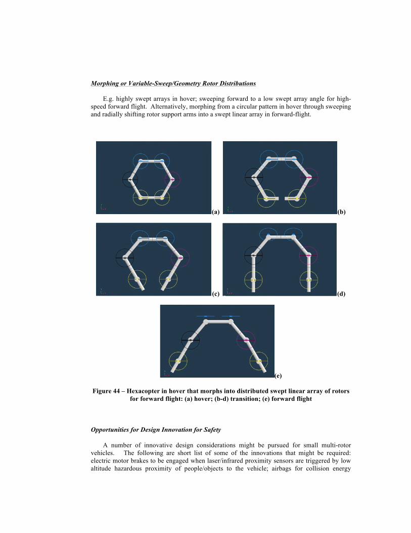
Morphing or Variable-Sweep/Geometry Rotor Distributions
E.g. highly swept arrays in hover; sweeping forward to a low swept array angle for high-speed forward flight. Alternatively, morphing from a circular pattern in hover through sweeping and radially shifting rotor support arms into a swept linear array in forward-flight.
(a) (b)
(c) (d)
(e)
Figure 44 – Hexacopter in hover that morphs into distributed swept linear array of rotors for forward flight: (a) hover; (b-d) transition; (e) forward flight
Opportunities for Design Innovation for Safety
A number of innovative design considerations might be pursued for small multi-rotor vehicles. The following are short list of some of the innovations that might be required: electric motor brakes to be engaged when laser/infrared proximity sensors are triggered by low altitude hazardous proximity of people/objects to the vehicle; airbags for collision energy

absorption; parachutes for high altitude failsafe aircraft recovery; aerodynamically efficient rotor protective shrouding and/or screens/vanes (see below discussion).
Further, multi-rotor missions will likely drive new operational procedures and design requirements. For example, avoiding or recovering from vortex ring state during descent is likely to have unique nuances for multi-rotor vehicle operation. Accordingly, it merits future computational and experimental study to consider the susceptibility and attributes of quadcopters, hexacopters, etc. to vortex ring state. Additionally, wake turbulence will likely also be a major design/operational consideration for multi-rotor vehicles both because of their small size and low-inertia but also because a number of proposed missions require such vehicles to operate in close proximity to buildings or surface terrain (cliffs, trees, etc.). Finally, obstacle and collision avoidance will be major considerations in the development of onboard sensors and avionics systems for such vehicles, given the likelihood that a majority of such missions will require flight below 400 ft. (120 m) AGL.
“Shrouding,” Fans-in-Wings, Fans-between-Wings, and Fans-in-Fuselage
A number of Mission A concepts incorporated the fundamental idea that the distributed rotors/propellers are protectively nested within wings or aerodynamically efficient structures, i.e. they fall within the “fan-between-wings” category of vehicles. This is, in itself, might be a rich design space to explore for enhancing the forward flight performance of multi-rotor configurations. Additionally, well-known, older concepts such as fans-in-wings and fans-in-fuselage configurations may gain renewed relevance for emerging multi-rotor vertical lift vehicles and missions.
Acoustics
If small vertical lift aerial autonomous vehicles begun as pervasive in our neighborhoods as leaf blowers, then acoustic considerations will become a major design driver. To expand on this point, the key acoustic challenge for small autonomous aerial vehicles, aka aerobots, operating in close proximity to people and ground infrastructure will not only be the question of how loud an individual vehicle is but instead what is the perception of that noise to people in their immediate vicinity (maybe only a few meters away) and, further, what is the impact when there might be literally hundreds on vehicles flying in their neighbors on a regular, minute by minute, basis. Rotorcraft acousticians have no comparable experience to draw on to even begin to address such questions and resolve this greater challenge. However, notionally multi-rotor configurations do have some design flexibility over conventional rotorcraft to potentially address future acoustic challenges.
Dynamic RPM
The electric-propulsion nature of most multi-rotor configurations, despite their limitations on flight endurance, do provide opportunities to examine new types of active rotor control technologies/strategies for noise mitigation. One of these potential approaches is the intentional use of dynamic rpm control for not only overall vehicle flight control but for source noise reduction.
Multi-Rotor-enabled Distributed Source Noise Suppression/Cancellation
Active rotor noise suppression/cancellation has seen many industrial applications. It has also been experimentally applied to cabin noise suppression for rotorcraft. For conventional rotorcraft, it does not appear to be feasible for mitigating external source noise (from the rotors

themselves) as perceived by passengers or the community being overflown. However, this noise reduction technique may have potential if applied to multi-rotor configurations.
“Facades” and Multirotor “Surrogates for Other Things”
There are several applications/missions wherein it may be desirable to disguise or to deemphasize the rotary-wing nature of a multi-rotor aerial vehicle. Among those applications/missions are the following: commercial advertisements; mobile artwork; camouflage for inflight and on-the-ground surveillance; representational surrogate vehicles/platforms for technology or operational demonstrations. Figure 45 is a conceptual illustration of a quadcopter vehicle with a spacecraft-like “facade” acting as a surrogate platform for laboratory and field-site terrestrial demonstrations of an “asteroid explorer” small spacecraft interacting with rock formations and cliff-faces to simulate investigations of such planetary bodies. A number of interesting design questions pose themselves for the development of such surrogate vehicles. Figure 46 presents a representative CFD result for such a surrogate “asteroid explorer” vehicle.
Figure 45 – Asteroid Explorer VTOL Surrogate Concept (background image courtesy of NSF)

Figure 46 – Rotor Wake Flow Field Prediction (velocity magnitude isosurface) of a Quadcopter with Facade simulating an Asteroid Explorer
Multirotors and Multi-Modality Mobility
Rotorcraft as robots as a design paradigm promises to enable wholly new applications for rotary-wing platforms. As example of this is the Ref. 25 “Titan Skeeter” planetary exploration robot which has three forms of mobility: flying, walking, and floating/skimming across liquid methane lakes; refer to Fig. 47. Another example is the combined hexapod and hexcopter robot of Ref. 26. The development of robotic rotorcraft with multi-mode mobility, coupled with a “surface interactive” nature, represents a very promising area of future investigation.
Figure 47 – “Titan Skeeter”: flight, walking, and locomotion on liquid surfaces

Concluding Remarks
This paper has provided discussion related to three different sub-classes of multi-rotor vehicle configurations. The focus of the paper was on the examination of a largely unexplored design space for an emerging class of small rotary-wing UAVs. Such a conceptual design study will yield insights into designing more aerodynamically efficient vehicles while at the same time preserving such vehicles’ intrinsic operational simplicity and low-cost.
The development and commercialization of multi-rotor vertical lift vehicles has to date been dominated by the RC hobbyist and consumer toy/electronics industries and not the traditional rotorcraft research and development community. But as the size and mission capability of such vehicles increases it is prudent to ponder whether it is time for the rotorcraft community to take a more active role. In this regards, a number of public service notional missions are considered in the context of modest-sized (10kg<TOGW<500kg) multi-rotor configurations of the three different sub-classes identified in this paper.
Acknowledgments
This work was performed through support from the Vertical Lift Hybrid-electric Autonomy (VLHA) project, which is a part of the Convergent Aeronautics Solutions (CAS) Project, which in turn is as part of the Transformative Aeronautics Concepts Program (TACP). The technical input of Carl Russell (NASA Ames) as to NDARC sizing code modeling of multi-rotor configurations is acknowledged. Additionally, the technical support of Katina Mattingly (Murray State University), Tyler Clark (Boise State University), Kiley Donohue (University of New Hampshire), and Ethan Wells (Wichita State University) is also gratefully acknowledged. Finally, the technical insights of Guillermo Costa and Pascal Lee as to the “Titan Skeeter” multi-modal mobility robotic concept and the “asteroid explorer VTOL surrogate” are gratefully acknowledged.
References
1Young, L.A., et al, “New Concepts and Perspectives on Micro-Rotorcraft and Small Autonomous Rotary-Wing Vehicles,” 20th AIAA Applied Aerodynamics Conference, St. Louis, MO, June 24-27, 2002.
2Young, L.A., “Aerobots as a Ubiquitous Part of Society,” AHS Vertical Lift Aircraft Design Conference, San Francisco, CA, January 18-20, 2006.
3Young, L.A., “Future Roles for Autonomous Vertical Lift in Disaster Relief and Emergency Response,” Heli-Japan 2006: AHS International Meeting on Advanced Rotorcraft Technology and Life Saving Activities, Nagoya, Japan, November 15-17, 2006.
4Young, L.A., “Feasibility of Turing-Style Tests for Autonomous Aerial Vehicle ‘Intelligence’,” AHS International Specialists’ Meeting on Unmanned Rotorcraft, Chandler, AZ, January 23-25, 2007.
5Young, L.A., “Enhanced Rescue Lift Capability,” 63rd Annual Forum of the AHS, International, Virginia Beach, VA, May 1-3, 2007.
6Young, L.A., “Rotorcraft and Enabling Robotic Rescue,” Heli-Japan 2010: AHS International Meeting on Advanced Rotorcraft Technology and Safety Operations, Ohmiya, Japan, Nov. 1-3, 2010.
7D’Andrea, R. and Kreigleder, M., Swiss Federal Institute of Technology (ETH), Zurich, Distributed Flight Array website; http://www.idsc.ethz.ch/Research_DAndrea/DFA; last accessed December 16, 2014.
8Rajagopalan, R. G., Baskaran, V., Hollingsworth, A., Lestari, A., Garrick, D., Solis, E., and Hagerty, B.,“RotCFD - A Tool for Aerodynamic Interference of Rotors: Validation and Capabilities,” Future Vertical Lift Aircraft Design Conference, San Francisco, CA, January 18-20, 2012.

9Young, L.A. and Derby, M.R., “Rotor/Wing Interactions in Hover,” NASA TM 2002-211392, April 2002.
10Johnson, W.R., Helicopter Theory, Princeton University Press, Princeton, New Jersey, 1980, pp. 142-146; pp. 64-67.
11Kroo, I., et al, “The Mesicopter: a Miniature Rotorcraft Concept (Phase II Final Report),” http://www.niac.usra.edu/files/studies/final_report/377Kroo.pdf; last accessed December 30, 2014.
12Mueller, T.J., “Aerodynamic Measurements at Low Reynolds Numbers for Fixed Wing Micro-Air Vehicles,” RTO/AVT/VKI Special Course on Development and Operation of UAVs for Military and Civil Applications, VKI, Belgium, September 13-17, 1999; http://www3.nd.edu/~mav/belgium.pdf; last accessed December 30, 2014.
13Stepniewski, W.Z. and Shinn, R.A., “Soviet Vs. U.S. Helicopter Weight Prediction Methods,” 39th Annual Forum of the American Helicopter Society, St. Louis, MO, May 9-11, 1983.
14Stepniewski, W.Z., “Some Weight Aspects of Soviet Helicopters,” 40th Annual Forum of the American Helicopter Society, Arlington, VA, May 16-18, 1984.
15Johnson, W., “NDARC: NASA Design and Analysis of Rotorcraft,” NASA-TP-2009-215402, December 2009.
16Circle Packing; http://en.wikipedia.org/wiki/Circle_packing; last accessed November 16, 2014.
17Circle Packing in a Circle; http://en.wikipedia.org/wiki/Circle_packing_in_a_circle; last accessed November 16, 2014.
18Weisstein, Eric W. "Circle Packing," From MathWorld – A Wolfram Web Resource, http://mathworld.wolfram.com/CirclePacking.html; last accessed November 16, 2014.
19Uhler, C. and Wright, S.J., “Packing Ellipsoids with Overlap,” SIAM Review, Society for Industrial and Applied Mathematics, April 2012.
20Jiang, Q., et al, “Analysis and Synthesis of Multi-Rotor Aerial Vehicles,” Proceedings of the ASME 2011 International Design Engineering Technical Conferences and Computers and Information in Engineering Conference (IDETC/CIE 2011), Washington, DC, August 28-31, 2011.
21Driessens, S. and Pounds, P.E.I., “Towards a More Efficient Quadrotor Configuration,” 2013 IEEE/RSJ International Conference on Intelligent Robots and Systems (IROS), Tokyo, Japan, November 3-7, 2013.
22Nikaido, B. E., “Ultra Portable and Rapidly Deployable Rotorcraft Platform for Tactical Compact Communications Relay”, M.S. Project, Mechanical and Aerospace Engineering Dept, San Jose State Univ., San Jose, CA, 2013.
23Mattingly, K., “Unmanned Aerial Systems Assessment: Initial Results and Implications,” Private communication; unpublished student intern research paper; NASA Ames Research Center; August 2014.
24Clark, T.P., “Unmanned Aerial Systems Assessment: Vehicle Description and Experimental Methods,” Private communication; unpublished student intern research paper; NASA Ames Research Center; August 2014.
25Costa, G., et al, “Design Studies of Vertical-Lift Aerial Vehicles for Unconventional Applications,” Private communication; unpublished student intern research paper; NASA Ames Research Center; August 2013.
26Integrated Hexapod and Hexacopter robot with multi-modality mobility; http://madlabindustries.com/hackerspace/projects-2/hexapod-quadcopter/; last accessed December 16, 2014.