conceptual design mba vacuum system overview · total thermal load due to radiation per sector is...
TRANSCRIPT

Conceptual Design MBA Vacuum System Overview
Herman Cease APS Upgrade Accelerator Vacuum Group October 15, 2014

Outline
APS-U Accelerator Vacuum System Vacuum chambers in the 40 arc sections Ray tracing Vacuum pressure simulations Installation plans R&D plans for a vacuum chamber sector mockup
H. Cease, MBA Vacuum System Overview Oct. 15, 2014 2

3
APS-U Accelerator Vacuum System: Bran Brajuskovic, J. Carter, H. Cease D. Fallin, J. Noonan, J. Nudell M. O’Neill, B. Rocke, B. Stillwell Operations: MOMs group
The Upgrade is evaluating a completely new DLSR magnet lattice and vacuum system
H. Cease, MBA Vacuum System Overview Oct. 15, 2014

MBA Vacuum Design Scheme, typical sector
4 H. Cease, MBA Vacuum System Overview Oct. 15, 2014
28 Beam chambers: Vacuum pumps: 7 Discrete active pumps, NEG strips in L-Bend ante-chambers, NEG
coating in FODO section between gate valves. Quad doublet: Chamber is a simple spool. Magnets incorporate fast correctors. L-bend: Magnet is C-shaped, we can use APS-style Al extrusions with antechambers. Multiplet: Space is tight except for two ~250 mm gaps between adjacent magnet per
section. There is also a light synchrotron heat load (~100 W/m). Simple spools with water cooling are used except where x-ray extraction requires a wider “key-hole” geometry.
FODO: Distributed absorber, and cooling. Thermal load (~1–1.5 W/mm). Required thermal performance suggests high-strength Cu chambers.
ID Chambers: Aluminum extrusions, ante chambers, NEG strips, design by ID group. May be a long-term interest in small diameter chambers -6 mm round.
Beam Direction

MBA Vacuum Design Scheme, typical sector
Vacuum System: Arc Chambers and photon extraction chambers, Pumping and gaging, Crotch Absorbers, BPMs: 12 per arc section, Interfaces, Vacuum design of ID straight chambers, Design of the chamber is done in the ID group. Transition chambers for beam injection, extraction, RF cavities. H. Cease, MBA Vacuum System Overview Oct. 15, 2014 5
Beam Direction

Quad Doublet Vacuum Chambers
6 H. Cease, MBA Vacuum System Overview Oct. 15, 2014
2 ¾” SST CF/QCF flanges
SST 904L to minimize shielding of fast-corrector fields. Internal Cu plate will minimize beam impedance.
No cooling tubes allowed to avoid perturbing fast corrector fields. No heating from direct bending magnet radiation is expected. If RF heating is an issue, two symmetric cooling channels may be an option.
S01A:VC1,2 S01B:VC1,2
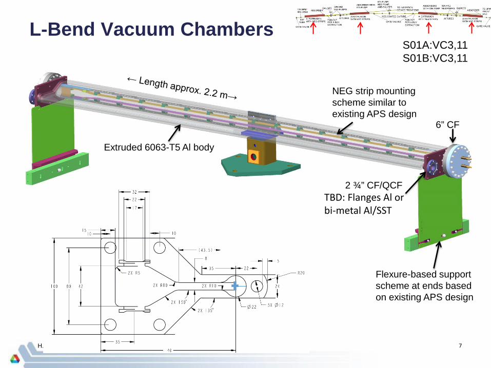
L-Bend Vacuum Chambers
7 H. Cease, MBA Vacuum System Overview Oct. 15, 2014
Flexure-based support scheme at ends based on existing APS design
2 ¾” CF/QCF
6” CF
Extruded 6063-T5 Al body
NEG strip mounting scheme similar to existing APS design
S01A:VC3,11 S01B:VC3,11
TBD: Flanges Al or bi-metal Al/SST

ID X-ray Beam Extraction Chambers
8 H. Cease, MBA Vacuum System Overview Oct. 15, 2014
CF/QCF flanges larger than 2 ¾” will be necessary. Welded Al or bi-metal Al/SST
Water cooling channel on inboard side either welded on or EDM’ed along with body. These chambers receive no direct heating from synchrotron radiation.
S01A:VC4,5
Height on x-ray beam side must be increased by 3 mm. A “bowtie”-like shape will result.
Aluminum 2219 Wire EDM’ed

Multiplet Vacuum Chambers
9 H. Cease, MBA Vacuum System Overview Oct. 15, 2014
2 ¾” CF/QCF flanges Welded Al or bi-metal Al/SST
Al 6063-T5 tube (possibly std. commercial item)
Al tube for water cooling welded to inboard side.
S01A:VC7,8,9,10 S01B:VC4,5,7,8,9,10
Synchrotron radiation hits outboard side but power is low (approx. 100 W/m)

FODO Chambers
10 H. Cease, MBA Vacuum System Overview Oct. 15, 2014
6 FODO chambers per sector, chambers between 500-1600mm length Water cooled Copper chambers: Radiation thermal load is 1-1.5 W/mm length or ~11 W/mm^2
NEG Coated between Gate Valves
Flange Absorber shields downstream elements
Downstream Chambers include photon extraction
slot for BM line

FODO Chambers
11 H. Cease, MBA Vacuum System Overview Oct. 15, 2014
1 – outer cooling channel
2 – inner cooling channel (optional)
3 – in-line absorber cooling
Optimizing for thermal cooling and minimizing impedance. Cooling system of VC18 is envisioned to have of two (might be
reduced to one) longitudinal cooling channels and a separate cooling circuit for in-line absorber

Integrated BPM / Bellows Assemblies
12 H. Cease, MBA Vacuum System Overview Oct. 15, 2014
2 ¾” QCF flanges
Rigid, non-magnetic base. Carbon fiber or SST 316L
3 tooling balls plus “flat” for precise alignment
Edge-welded bellows to decouple thermally-induced chamber motion from BPMs
RF “button” BPM similar to those commercially available from Insulator Seal and others.
RF liner inside is TBD
Threaded fasteners for alignment.
Estimated insertion length is 125 mm

Synchrotron Radiation Ray Trace: Absorbers
13 H. Cease, MBA Vacuum System Overview Oct. 15, 2014
APS transition absorber for use upstream of shielded gate valves and pump-out liners: S01A:TA1,2 S01B:TA1,2
APS boot absorber for the end absorbers on L-bend chambers: S01A:EA1, S01B:EA1, S01B:EA2
MAX-IV crotch absorber for the ID beam extraction crotch: S01A:CA1
APS end absorber for the 3PW extraction crotch: S01B:CA1 and end absorber: S01A:EA2
MAX-IV inspired bellows absorber

Ion Pump, and Gauge Insertion
14 H. Cease, MBA Vacuum System Overview Oct. 15, 2014
ID crotch absorber will be mounted in outboard port of S01A:VC6
2X right angle valves for rough pumping and purge
Cold cathode and thermocouple gauges
RF liner inside is TBD
Transition absorber to protect liner from bending magnet radiation. Vacuum cross
modified for minimum insertion length. Ta/Ti (noble gas
pumping) ion pump
Right angle valve (back) so that entire tree can be removed without venting chambers
S01A:VC6,15 S01B:VC6
Estimated insertion length is 250 mm
RGA will be mounted in outboard port of one of S01A:VC15 OR S01B:VC6

Synchrotron Radiation Ray Trace: Heat Loads
15 H. Cease, MBA Vacuum System Overview Oct. 15, 2014
Ray traces initial performed with CAD program and analytically. Total thermal load due to radiation per sector is 11.2 kW Bending magnet radiation power is concentrated in the center (FODO) section
and at the ends (close to the ID beam), distributed power is 4kW. Glidcop lip absorbers needed in FODO section to shadow downstream flanges
and bellows. Maximum power density on the FODO section chamber wall is ~11 W / mm2. Maximum power density on an absorber is ~50 W/mm2. BM crotch absorber is 2.2kW, discrete absorber located in L-bend chamber –
antechamber.

Overview & Status: Vacuum Analysis
16 H. Cease, MBA Vacuum System Overview Oct. 15, 2014
Initially 1-D analytical calculations. – Has many limitations, but is a good first pass to compare initial designs. Using VacCalc.
Working with SynRad and MolFlow+. – Utilizes a parameterized 3-D CAD model for the sector geometry. – Developing detailed 3-D simulations for the entire sector. – Can be used as a ray tracing tool and for steering conditions. – Includes power at absorbers and chamber walls. – Pressure analysis at absorbers and the entire sector.
Sector pressure profile 1-D Analysis VacCalc
Power deposited on L-Bend Absorber 3-D Analysis SynRad
L-Bend chamber Pressure 3-D Analysis MolFlow

Design comparison, 4 vs 7 ion pumps:
7x 45 L/s pumps with cartridge pumps at cross stations
4 X100 L/s pumps
nTorr
nTorr
H. Cease, MBA Vacuum System Overview Oct. 15, 2014 17

Design comparison, CH4 pressure: CH4 pressure after 20 days at full current
4 X100 L/s pumps
25% of total
20% of total
7x 45 L/s pumps with cartridge pumps at cross stations
nTorr
nTorr
H. Cease, MBA Vacuum System Overview Oct. 15, 2014 18

SynRad: Ray tracing and synchrotron radiation
H. Cease, MBA Vacuum System Overview Oct. 15, 2014 19
SynRad Development. – Utilizes a parameterized 3-D CAD model for the sector geometry. – Determines beam thermal profile both vertical and longitudinal on chamber walls and absorbers. – Simulates Photon Stimulated Desorption. –Can be used as a ray tracing tool and for steering conditions.

H. Cease, MBA Vacuum System Overview Oct. 15, 2014 20
Vacuum pressure profile with 3-D simulation tool MolFlow

Removal, Installation, function tests with beam
H. Cease, MBA Vacuum System Overview Oct. 15, 2014 21
1 year total duration Vacuum chambers pre-installed on girders. Integrated and pre-aligned with magnets. Chamber assemblies same length as girder. 9 integrated support, magnet, vacuum assemblies installed
in the tunnel per each arc section. ~3 months allocated for closing the vacuum system.

Overview & Status Risks and R&D plan
H. Cease, MBA Vacuum System Overview Oct. 15, 2014 22
Vacuum System Risk List. – Vacuum pressure requirement exceeded
– Consequence is operating at less beam current – Installation duration exceeded
– Delayed integrated testing. – Impedance budget exceeded
– Consequence is operating at less bunch current – Temperature of component is higher than expected
Vacuum System R&D Plan. – Sector mockup
– Fabrication, cooling methods, alignment, stability, installation procedures, – Vacuum pressure on the sector mockup
– Pressure can be measured across the sector with simulated loads at absorbers.
– Impedance measurements – Stretched wire testing of components – NEG coating measurements

Summary
H. Cease, MBA Vacuum System Overview Oct. 15, 2014 23
Vacuum system design drivers: – Magnet bore diameters are small
– Limited Space for ante-chambers and NEG strips. – Ex-situ activation of NEG coated chambers.
– Installation time requires minimizing bake out and activation durations. – The number of NEG coated chambers requiring ex-situ activation are minimized. – NEG coated chambers are isolated with gate valves, allowing installation under vacuum.
Vacuum System Design developments: – Parameterized CAD model – Synchrotron radiation power loads on chamber walls and
absorbers modelled analytically and with 3-D simulations. – Vacuum pressure across the sector modelled with 1-D and 3-D
simulations tools. – Chamber fabrication techniques
– High heat load in FODO section, requires specialized flange absorbers – Vacuum flange and vacuum flange to chamber material bonding techniques
are being evaluated.
Vacuum system conceptual design of arc chambers is developed.

Backup Slides
H. Cease, MBA Vacuum System Overview Oct. 15, 2014 24

Integrated Assemblies
25 H. Cease, MBA Vacuum System Overview Oct. 15, 2014
Vacuum components integrated inside the assembly. Chamber assembly with utility pigtails mounted in lower half. Top half closes the unit.
BM: Straight Multiplet Pump out chamber