conceptual design study for the electric cargo … design...conceptual design study for the electric...
TRANSCRIPT

1
Presented to
The Port of Los Angeles
June 15, 2006
Conceptual Design Study for the Electric Cargo Conveyor (ECCO) System
Final Review Meeting

2
Agenda – June 15, 2006
• Arrive at GA and check in 9:30 AM
• Tour GA maglev test track 9:45-10:30 AM
• Welcome (Mike Reed, GA VP) 10:45 AM
• Introductory comments (Port of LA) 10:50 AM
• Project overview (Sam Gurol, GA) 11:00-11:10 AM
• System requirements (Bob Baldi, GA) 11:10-11:30 AM
• System architecture (Ken James, CSULB) 11:30-11:50 AM
• Buffet lunch served (working) 11:50 AM
• Planned alignment (Tom Riester, Mackin) 12:00-12:30 PM
• Maglev components (Phil Jeter, GA) 12:30-12:50 PM
• Comm. & signaling (Denny Pascoe, US&S) 12:50-1:15 PM
• Budgetary cost estimates (Daryl Bever, GA) 1:15-1:40 PM
• Next steps (Sam Gurol, GA) 1:40-1:50 PM
• Concluding remarks (Port of LA) 1:50-2:00 PM
• Adjourn 2:00 PM

3
Project Overview
Sam Gurol
Director, Maglev Systems
General Atomics

4
The General Atomics ECCO Study Team
Civil EngineeringSystem Architecture
Communications & SignalingMagnetics Analysis
Prime Contractor and
Maglev Systems
5
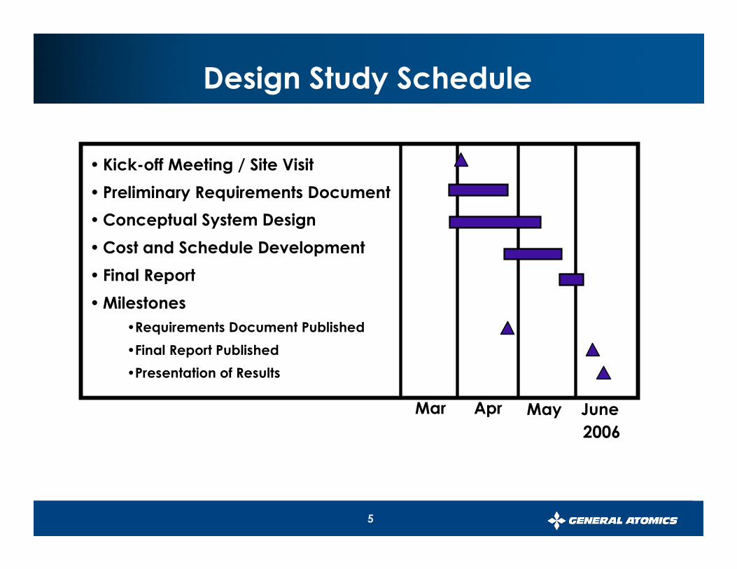
Design Study Schedule
Mar
• Kick-off Meeting / Site Visit
• Preliminary Requirements Document
•Conceptual System Design
•Cost and Schedule Development
• Final Report
•Milestones
•Requirements Document Published
•Final Report Published
•Presentation of Results
Apr May June
2006

6
Maglev Engineers Walking the Alignment – 4/20/06

7
• Container trips per day: 5,000 (2,500 per direction)
• Container size: Up to 40’
• Container weight: 30,482 Kg (67,200 lbs)
• Operation hours: 24 hours
• Alignment length: 7.5 km (4.7 miles)*
* (Terminal Island to SCIG)
Port of LA Study Guidelines
8
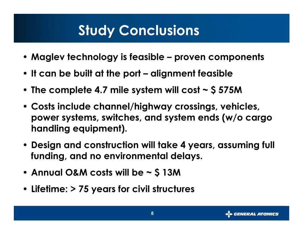
Study Conclusions
• Maglev technology is feasible – proven components
• It can be built at the port – alignment feasible
• The complete 4.7 mile system will cost ~ $ 575M
• Costs include channel/highway crossings, vehicles, power systems, switches, and system ends (w/o cargo handling equipment).
• Design and construction will take 4 years, assuming full funding, and no environmental delays.
• Annual O&M costs will be ~ $ 13M
• Lifetime: > 75 years for civil structures

9
System Requirements& Preliminary Technical Selections
Bob Baldi
Senior Program Manager
General Atomics
10
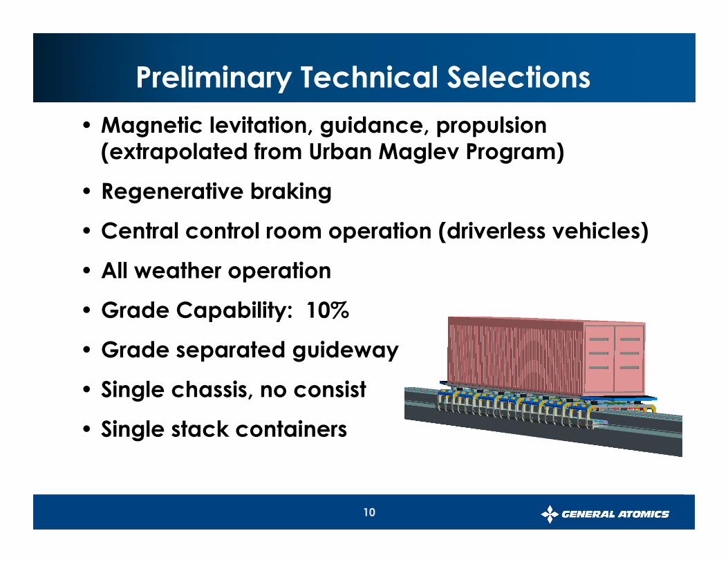
• Magnetic levitation, guidance, propulsion (extrapolated from Urban Maglev Program)
• Regenerative braking
• Central control room operation (driverless vehicles)
• All weather operation
• Grade Capability: 10%
• Grade separated guideway
• Single chassis, no consist
• Single stack containers
Preliminary Technical Selections

11
• Magnetic levitation height: 2.5 cm (1.0 inch)
• Length of levitation array: 13.6 m (45 feet)
• Minimum turn radius: 100m (328 feet)
• High speed turn radius: 800m (2,624 feet)
• Propulsion Energy Supply: Dual source
Preliminary Technical Selections (cont.)

12
Preliminary Technical Selections (cont.)
• Maximum Speed: 145 kmph (90 mph)
• Acceleration: 1.6 m/s2
• Trip time (high-speed section): 3.5 min.
• Average speed: ~122 kmph (~80 mph)
• Headway: 20 seconds
• Maximum g loading:� Longitudinal, vertical, lateral (nominal): 0.16 g (1.6 m/s2)
� Longitudinal (emergency): 0.36 g (3.6 m/s2)
• External Noise Limit: 72 dBA
• Availability: > 99%

13
Vehicles in High Speed Section
SwitchSwitch
Loading AreaLoading Area
Loading Area
Overall System Architecture
• 2,500 containers/direction/day
• Double track system
• 36 vehicles per track (72 total)
• 18 vehicles being loaded/unloaded
• Three regimes:
� Low speed (loading/unloading)
� Acceleration/deceleration
� High speed cruise (90 mph, 20 sec. headway)
14
System Architecture
Ken James
Professor, Electrical Engineering
Professor, Computer Science
California State University Long Beach

15
• Conveyor Technology Infers Two Designs
• A Continuous Loop
• A Bidirectional Conveyor
• Bidirectional Approach Selected
•Minimized Required Terminal Space
•Facilitated Unload/Load Process
•Requires Bifurcated Ends to Effectively Use Single, High-Speed Guideway
• Operating Scenario Based on Bidirectional Approach
•Timing Flow Analysis Performed by General Atomics
•Included Technology, Safety, and Switching Considerations
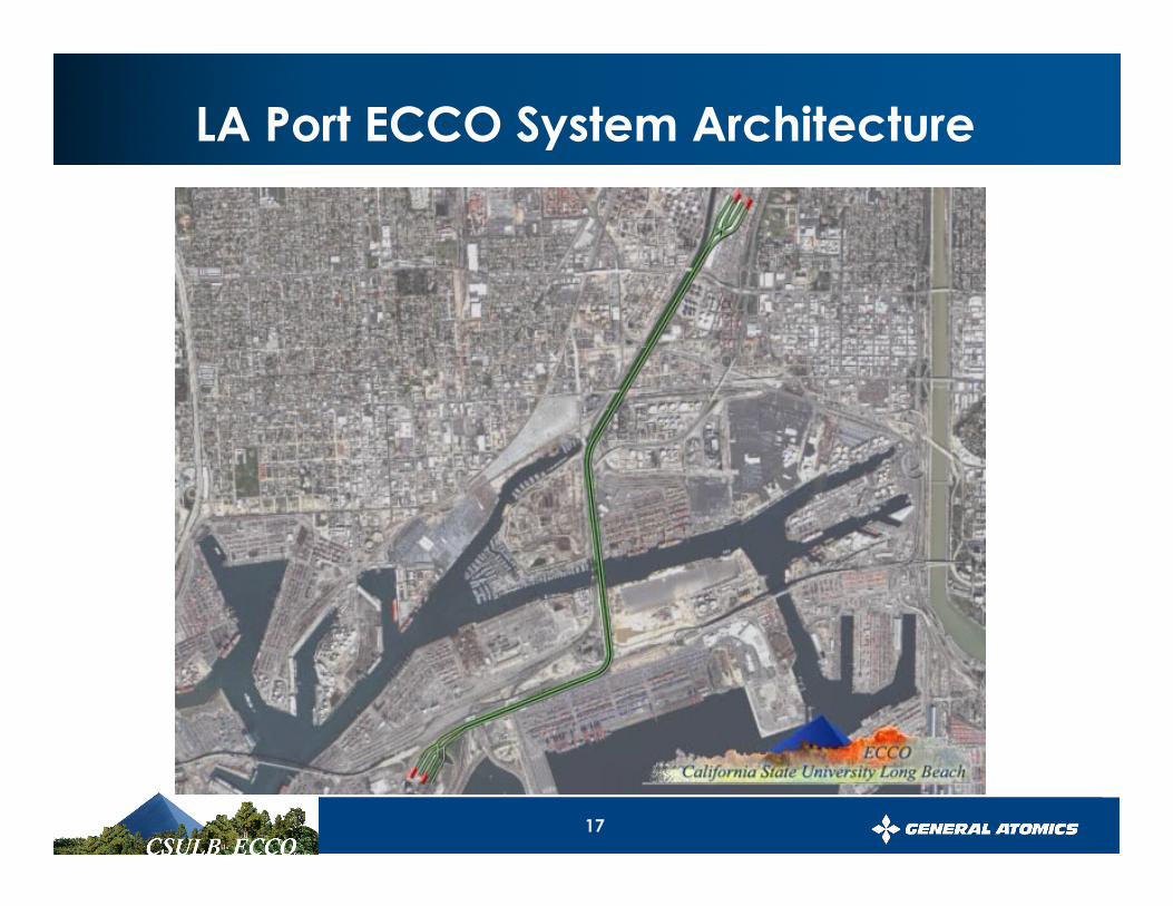
LA Port ECCO System Architecture

16
•Two Parallel, Bidirectional Systems, Each with 36 Carriages are Required to Meet Throughput Requirements
•Systems Travel between Port and SCIG Terminals 180º out of Phase
• Two 18 Carriage Sections on Switched Spurs at Terminals
• Evens Unload/Load Labor and Equipment Requirements
LA Port ECCO System Architecture
17
LA Port ECCO System Architecture

18
System Architecture (container flow timing)
Key
Acceleration
High Speed Mode - South
High Speed Mode - North
Load/Unload - South End
Load/Unload - North End
Wait
Container Carriages 1 through 36 for Each of the Two Parallel Conveyor Systems
Container Carriages Round-Trip Cycle of 32+ Minutes

19
• Railed Straddle Cranes Considered Most Effective at Both Terminals
• Unload/Load Process on Spur Coupled with a Container Storage Magazine
ECCO Unload/Load Process
• Would Provide “Slack” between the Somewhat Random Truck Arrival to the Steady Conveyor Operation
• Avoids Truck Queues at the ECCO Port Terminal

20
• Analysis of the selected ECCO design shows a 6.7 minute unload/load process at the front of each spur, and an 18 minute unload/load time at the back of the spur
• Suggests nonlinear crane usage
• Four straddle cranes (one for the first 3 carriages, one for thenext 4, one for the next 5, and one for the last 6) are in-line rail-mounted to simultaneously unload/load the 18 ECCO carriages on the spur
• While present straddle crane/work crew operational data indicates that this ECCO system unload/load process will produce the required 5,000 container moves per day, automation of the cranes and enhancements to the proposed
system architecture will likely improve system throughput
ECCO Unload/Load Process

21
ECCO Unload/Load Process

22
Conclusion
The system architecture meets the projected throughput requirements

23
Planned Alignment
Thomas E. Riester, P.E.
Vice President – Transportation Services
Mackin Engineering Company
24
•Studied Terminal Island Transfer Facility to ICTF Transfer Facility
•Total Distance 5.73 miles (SCIG is 4.7 miles)
•Two Alternative Alignments
•Red
•Green
ECCO System Alignment

25
• Length 5.73 miles to ICTF (4.7 miles to SCIG)
• Parallels north side of Seaside Avenue / Ocean Boulevard, then follows Port of LA Study Alignment
• Minimum provided horizontal radius
�400 Feet over Terminal Island Freeway
�500 Feet Over Seaside Avenue
�10 Additional horizontal curves from 1400’ to 11,500’
• Minimum allowable horizontal radius 328’
Red Alignment

26
Figure 1a – ECCO System Alignment
Green Alignment
Red Alignment
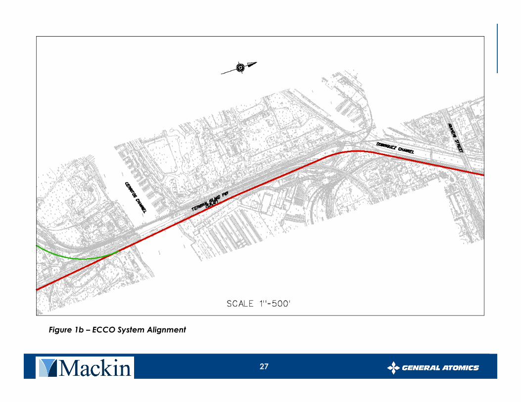
27
Figure 1b – ECCO System Alignment

28
Figure 1c – ECCO System Alignment

29
Figure 1d – ECCO System Alignment
30
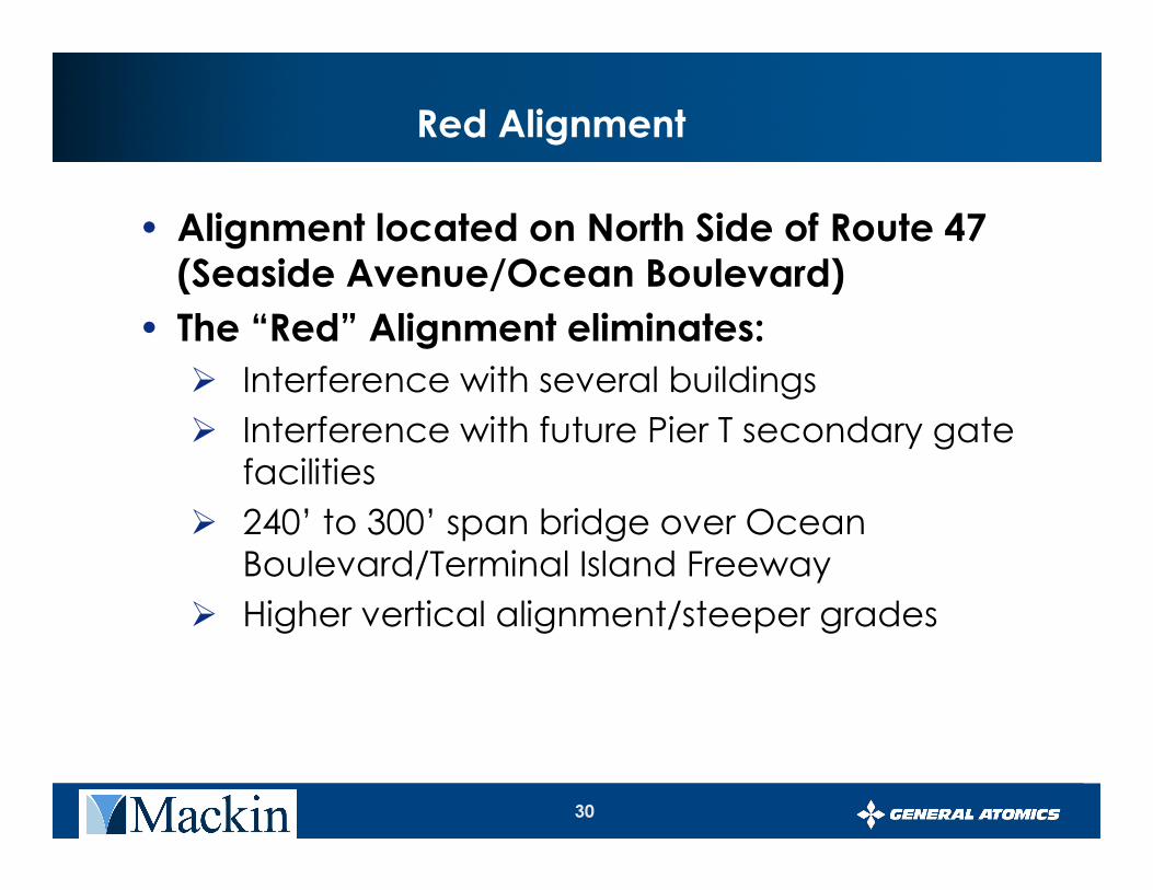
Red Alignment
• Alignment located on North Side of Route 47 (Seaside Avenue/Ocean Boulevard)
• The “Red” Alignment eliminates:
� Interference with several buildings
� Interference with future Pier T secondary gate facilities
� 240’ to 300’ span bridge over Ocean Boulevard/Terminal Island Freeway
� Higher vertical alignment/steeper grades
31
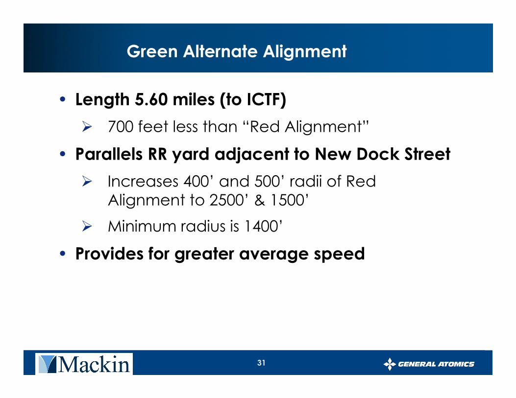
Green Alternate Alignment
• Length 5.60 miles (to ICTF)
� 700 feet less than “Red Alignment”
• Parallels RR yard adjacent to New Dock Street
� Increases 400’ and 500’ radii of Red Alignment to 2500’ & 1500’
� Minimum radius is 1400’
• Provides for greater average speed

32
Figure 1a – ECCO System Alignment
Green Alignment
Red Alignment

33
Figure 1b – ECCO System Alignment

34
Vertical Alignment (Red & Green Alternative)
• 30’ nominal height above existing ground
• Increased where necessary to achieve grade change, or clearance over RR tracks
• Vertical clearances
� 16.5’ over local streets and Caltrans
� 24.5’ over RR
� 58’ over Cerritos Channel – Mean Lower Low Water (MLLW)
• Minimum allowable radius 3281’
• Minimum provided radius 6000’

35
Vertical Alignment – Average, Maximum Grades
• Alignment is level at stations
• Grades generally vary – .4% to +.4%
• Maximum grades at Anaheim Street Crossing
� +2.28%, - 1.64%
• Anaheim Street is the controlling feature
• Maximum grades at the Cerritos Channel
� +1.17%, -1.06%
• Maximum allowable grade 10%

36
Guideway
• Elevated Guideway – Provides clearance over all facilities and obstacles
• Guideway Structure
� Hybrid Concrete Girder – High-strength concrete and steel fibers
� Precast Construction or precast and segmental construction (Long spans)
� Precast Construction – quick construction, minimal disruptions

37
Guideway (Continued)
• Average Span Length – 80’ to 120’
• Maximum Spans 155’ to 240’ (over Cerritos Channel) and expressway ramps
• 4720’ of Guideway requires spans greater than 120’ (16% of the Red Alignment)

38
Typical Hybrid Girder Cross-Section

39
Guideway Piers
• T-Piers are the typical pier
• L-Piers used in areas of tight clearance
• Top T or L Section supported by circular pier shafts and singular circular caisson foundations.
• Singular caisson foundations�Fast Construction
�Minimal space
�Minimal vibration
• Cast-In-Place or Pre-Cast Concrete Construction

40
Guideway Piers – Typical Cross-Section

41
Right of Way Issues
• The Alignment will be located within right of way owned by -
� Port of LA
� Port of Long Beach
� Caltrans – Route 47
o Ocean Boulevard
o Terminal Island Freeway
� Railroads – Owned by Ports
o 1500’ North & South of Anaheim Street
� Private Property ?

42
Right of Way Issues (Continued)
• Agreement (permanent easement) required to occupy Port of Long Beach, Caltrans
• Private properties may require purchase of right of way
• Minimal, if any, building / facility impacts

43
Conclusion
The alignment is feasible and can be constructed with conventional methods

44
Presented by
Phil Jeter
Chief Engineer
General Atomics
Maglev Components
45
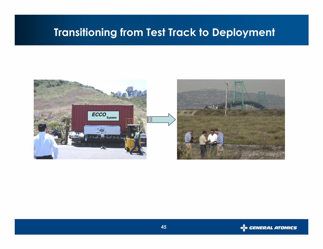
Transitioning from Test Track to Deployment
ECCOSystem
46
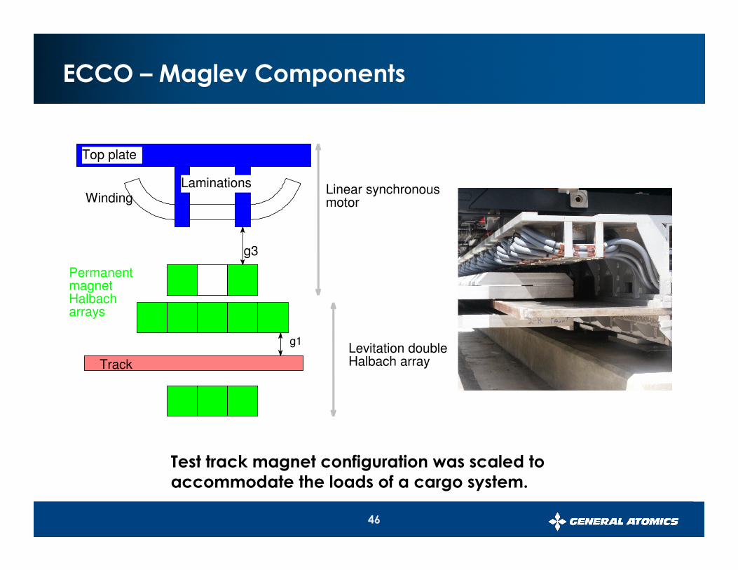
ECCO – Maglev Components
g1
g3
Track
Levitation double Halbach array
Linear synchronous motor
Top plate
Winding
Laminations
Permanent magnet Halbach arrays
Test track magnet configuration was scaled to accommodate the loads of a cargo system.

47
Magnet Modules
• Magnet blocks
– Neodymium-Iron-Boron (NdFeB)
– Subdivided into sub-assemblies
– Loaded into the magnet modules
• Chassis Assembly
– Magnet modules are then mounted to the chassis supports
Chassis Assembly
Magnet Modules

48
Guideway Modules
• Guideway Modules– Hybrid Guideway Girder
• Steel Fiber Reinforce Concrete (SFRC)
– Linear Synchronous Motor– Levitation Track– High Speed Turns (144 km/hr, 90 mph)
• 800 meter min. turn radius• 11.50 Cant Angle
LevitationTrack
Structural Embedment Typical
1200 (47.3”)
2000 (78.7”)
900 (35.4”)
LSM
Girder

49
Concrete Mix Was Developed by GA/SDSU
• Conventional Reinforced Concrete– Rebar design
• Cost = $152/m ($46.30/ft)• Flexural Allowable = 34.5 MPa
(5,000 psi) • Modulus = 28,275 MPa (4.1x10⁶
psi)• Weight = 1396 kg/m (938 lbs/ft)
• SFRC Design– Smaller, lighter, stiffer and less
expensive– Simple construction for complex
geometry– Tested per American Standards
Institute (ACI) standards • Cost = $115/m ($35/ft)• Flexural Allowable = 83 MPa
(12,035 psi)• Modulus = 49,655 MPa (7.2x10⁶
psi) • Weight = 770 kg/m (517 lbs/ft)
BrakeEmbedment
Litz TrackSupport Embedment
LSM MotorSupport Embedment
Litz Track ClampInterface Embedment
Litz TrackSupport Embedment
LSM MotorSupport Embedment
Litz Track ClampInterface Embedment
Fibers in the SFRC Concrete

50
Container Carrier Vehicle
• Characteristics:– Payload
• 33 tons
– Levitation propulsion• 10 tons
– Chassis structure:• 9 tons
– Total• 52 tons ~(115,000lb)
• Vehicle Dimensions:– Length
• 12.18 m (40ft)
– Width• 2.44 m (8 ft)
– Height• 2.90 m (9.5 ft)
7 Chassis Halves

51
Control System
Inverter Cabinet Interior View
Vehicle Control Computer
Central Control Unit
Pulse-Width-Modulation Card
Speed and Location Sensor

52
Conclusion
Cargo maglev can be readily extrapolated from proven GA Urban Maglev test track components.

53
Presented by
Denny Pascoe,
Vice President - Union Switch and Signal
Communication and Signaling
Union Switch & Signal

54Union Switch & Signal
� Cargo Vehicle Carborne Equipment,
� Signaling, and
� Communications
� CCTV
Union Switch & Signal’s Participation in the LA Port Project

55
18 Cargo Vehicleson each storage track
Two Independent Transportation Systems
Union Switch & Signal
Each Independent Transportation systems willhave its own Communications and
Train Control Center

56
Cargo Vehicles
LSM winding segments
(( ))(( ))(( ))(( ))
Operating Rule:
One LSM segment must be ‘clear’ of a vehicle for system to continue operating
Simple Operating Rule
Union Switch & Signal

57
Control of each Transportation Systems
Union Switch & Signal
Transportation system:
� A Digital Communication System (DCS) which communicates between each cargo vehicle and the CAD system,
� Cargo vehicle equipment that determines its location on the Guideway,
� Cargo vehicle equipment that determines its speed on the Guideway,
� A CAD system that determines via the position of each cargo vehicle if the operating rule is true, and
� Logic that determines if the operating rule is not true, and commands are sent to each inverter through the GA network inverter control to shut down and each cargo vehicle to apply emergency braking.

58Union Switch & Signal
Components:
� Wayside
� Central Office
� Vehicle
� Communications
� CCTV
Control System Components
59
Ethernet dual ring
GA Remote controlled cameras
Cargo Vehicle
SwitchI/O
SwitchI/O
Local Operator Workstation
Remote Terminal
Local Operator Workstation
Central Office
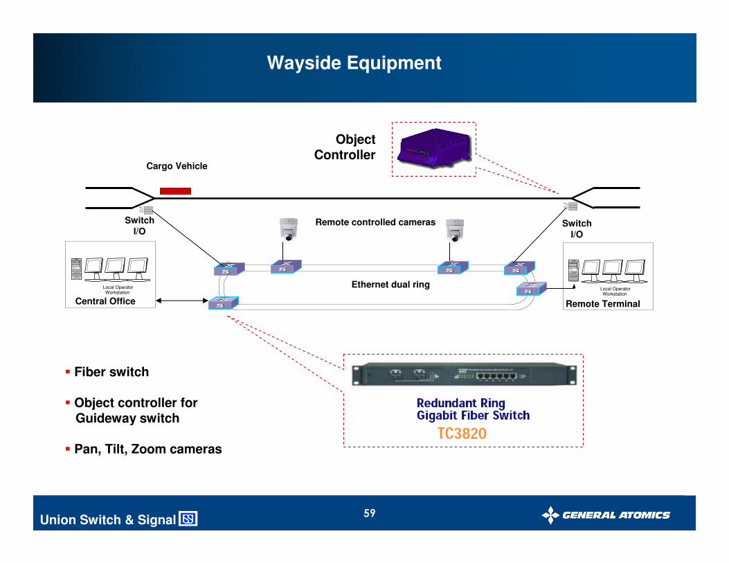
Wayside Equipment
Union Switch & Signal
� Fiber switch
� Object controller forGuideway switch
� Pan, Tilt, Zoom cameras
ObjectController

60
Ethernet dual ring
GA
Operator 1Workstation
Operator 2Workstation
Local Operator Workstation
Central Control Office
Central Control Remote Terminal
CAD
DCS
CCTV + Voice
CommunicationTower for 100%
coverage
GA INVController
Remote controlled cameras
Cargo Vehicle
SwitchI/O
SwitchI/O
Central Control Equipment
Union Switch & Signal

61
Central Control Functionality
Union Switch & Signal
Central Control
� Initiate request for vehicle movements
� Block storage tracks
� Select switch positions
� Support display of
� vehicle location
� switch position
� vehicle load/unload status
� web-based viewing
� event logging
� replay of events

62
Cargo Vehicles
LSM winding segments
(( ))(( ))(( ))(( ))
Operating Rule:
One LSM segmentmust be ‘clear’ ofa vehicle for systemto continue operating
ComputerAided
Dispatch
DCS
(( ))
Enforcement System
Vehicle – Central Communication
Union Switch & Signal

63
Cargo Vehicle
GPSSatellite
GA
On-Board Computer
(( ))
relay
DC input
EmergencyBrakes
RFModem
DGPSReceiver
PICCPU
DC/DCPS
Data: Vehicle to CentralLocation (lon/lad)SpeedBrake status
Central to VehicleBrake request
BrakeIndication
Union Switch & Signal
Vehicle Equipment
PIC CPU
RF ModemM12+
DGPS
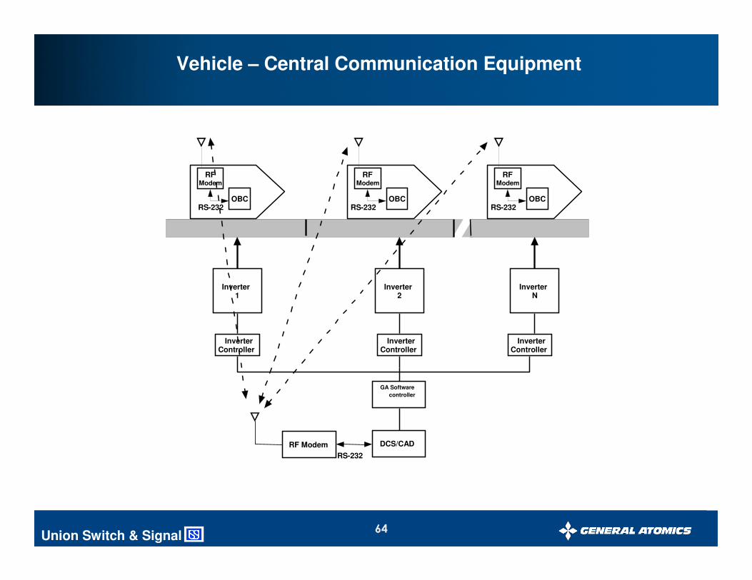
64
Inverter2
Inverter1
DCS/CADRF Modem
RS-232
GA Software
controller
RS-232OBC
RFModem
RS-232OBC
RFModem
InverterN
RS-232OBC
RFModem
InverterController
InverterController
InverterController
Union Switch & Signal
Vehicle – Central Communication Equipment

65
Ethernet dual ring
GA Remote controlled cameras
Cargo Vehicle
CCTV
Central Control
CCTV Equipment
Union Switch & Signal
Surveillance of Guideway� Cargo Vehicle� Intruders
Using ‘Video-Motion’ technology

66
Ethernet dual ring
GA
Operator 1Workstation
Operator 2Workstation
Local Operator Workstation
Central Control Office
Central Control Remote Terminal
CAD
DCS
CCTV + Voice
CommunicationTower for 100%
coverage
GA INVController
Remote controlled cameras
Cargo Vehicle
SwitchI/O
SwitchI/O
On-Board Computer
(( ))
relay
DC input
EmergencyBrakes
RFModem
DGPSReceiver
PICCPU
DC/DCPS
BrakeIndication
GPSSatellite
Control System Block Diagram
Union Switch & Signal

67
Conclusion
The communication and signaling system uses proven, safety-certified components

68
Presented by
Daryl Bever,
Chief Maglev Manufacturing Engineer
General Atomics
Budgetary Cost Estimates
69
Study Task 3 & 4 Objectives
• Create Work Breakdown Structure
• Create Engineering, Construction, and Commissioning Schedule
• Prepare Budgetary Capital Cost Estimate
• Consistent & Traceable to WBS / Schedule / DBS
• Prepare Budgetary O & M Cost Estimate

70
Cost & Schedule Assumptions
• Budgetary cost estimate for planning purposes.
• Constant year 2006 dollars.
• Commercial factors for contingency, warranty, facility, capital cost of
money, and fee are included.
• Right-of-way and environment impacts costs are not included.
• Channel and freeway crossings are included.
• Design concept is a close derivative of current passenger maglev concept.
• Site-specific engineering is a 1.5 year activity.
• Construction is a 3 year activity.
• Commissioning occurs 3 months after completion of construction.
• Throughput – 2500 40’ containers per direction / per year.
• Operation – 24/7.
• Length of project – 4.7 miles.
• Cargo handling equipment not included.
• Driverless operation.
• Single container maglev chassis (no consist).

71
Preliminary Schedule
� Distinct Phases
– Project Site-Specific / Detail Engineering
– Project Construction
– Commissioning
– Operation
Task Name
Site Specific / Detail Engineering
Construction
Commissioning
Operation
Year 1 Year 2 Year 3 Year 4 Year 5

72
Preliminary WBS Level 3
ECCO-System Project
10000
Site-Specific/Detail Engineering
30000
Test & Evaluation
31000
Safety Planning
32000
FMEA
33000
Test Planning
34000
Component Acceptance Test
40000
Operation
41000
Management
42000
SystemOperation
43000
44000
SystemMaintenance
45000
Training
46000
Energy
Spare Parts
20000
Construction
21000
Vehicle
22000
Girder/Levitation/Prop Systems
23000
MaintenanceYard/Equipment
24000
Energy SupplySystem
25000
Ops/Cmd/CntlSystems
26000
Guideway
27000
Civil Structures
28000
Right-of-Way /Corridor
11000
Vehicle
12000
Girder/Levitation/Prop Systems
13000
MaintenanceYard/Equipment
14000
Energy SupplySystem
15000
Ops/Cmd/CntlSystems
16000
Guideway
17000
Civil Structures
18000
Right-of-Way /Corridor
35000
System Acceptance Test
36000
Training
37000
Energy
29000
Project Integration
19000
Project Integration
38000
Project Integration

73
Preliminary GA Organization (Construction)
ECCO System
Site Manager
Technical
Support
Liaison
Engineering
Finance
Administration
Legal
Reliability/
Safety/
QAAgency
Mgmt Support
Contracts/Purchasing
- Non-conformance Evaluation- Configuration Management- Interface Management
-Government Affairs-Public Relations-Regulatory Interface
-Project Administration-Property Management-Cost Account Mgmt-Scheduling-Estimating Support
Maglev Projects
Program Manager
Subcontractor/
Construction
Coordination
- Design- Analysis
Human Resources
Systems
Engineering

74
Project Costs
Commissioning
4%
Construction
89%
Site-Specif ic /
Detail Engineering
7%
Site-Specific / Detail Engineering 40,359,000$
Construction 510,149,000$
Total Engineering & Construction 550,508,000$
Commissioning 24,070,000$
Total 574,578,000$

75
Breakdown of Project Construction Cost
Project Integration
6%Civil Structures
2%
Guidew ay
16%
Operation /
Command /
Control Sys
2%
Maintenance
Yard / Equipment
2%
Energy Supply
Systems
20%
Liaisson
Engineering
2%
Vehicles
11%
Hybrid
Girder/Levitation/
Propulsion
Modules
39%
Liaisson Engineering 12,500,000$
Vehicles 55,505,000$
Hybrid Girder/Levitation/Propulsion Modules 194,074,000$
Maintenance Yard / Equipment 11,234,000$
Energy Supply Systems 103,326,000$
Operation / Command / Control Sys 10,721,000$
Guideway 79,875,000$
Civil Structures 10,375,000$
Right-of-Way / Corridor -$
Project Integration 32,539,000$
Total 510,149,000$

76
Budgetary Cash Flow
Year 1 Year 2 Year 3 Year 4 Total
Site-Specific / Detail Engineering 28,251,300$ 12,107,700$ 40,359,000$
Construction 153,044,700$ 255,074,500$ 102,029,800$ 510,149,000$
Total Engineering & Construction 28,251,300$ 165,152,400$ 255,074,500$ 102,029,800$ 550,508,000$
Commissioning 24,070,000$ 24,070,000$
Total 28,251,300$ 165,152,400$ 255,074,500$ 126,099,800$ 574,578,000$

77
Annual O & M Costs
Total Annual O&M Cost is $12.7M
Annual Operations Costs Personnel Salary & Benefits Cost
Labor
Control Center Operator 10 60,000$ 600,000$
Security 5 40,000$ 200,000$
Total Labor 800,000$
Non-Labor
Enengy 8,212,500$
Management & Administration 200,000$
Total Annual Operations Costs 9,212,500$
Annual Maintenance Costs Personnel Salary & Benefits Cost
Labor
Vehicles 6 90,000$ 540,000$
Electrical Systems 8 90,000$ 720,000$
Guideway Inspection and Maintenance 5 90,000$ 450,000$
Total Labor 1,710,000$
Non-Labor
Spare Parts 1,800,000$
Total Annual Operations Costs 3,510,000$

78
Key Cost Elements
• Construction Cost per dual track mile (excluding vehicles)
• Vehicle Cost (each)
• Annual O & M Cost
~ $97M
~ $0.8M
~ $13M

79
Concluding Remarks

80
Benefits of Maglev Cargo
• Greatly improves infrastructure of LA Port which is a very high volume trade corridor of National significance for freight movement.
• Improves efficiency to accommodate the movement of freight in and out of the Port.
• Enhances the capacity of the Port.
• All electric operation substantially reduces pollutant emissions.

81
Next Steps
• Perform detail site-specific engineering
• Develop procurement, manufacturing plan to meet schedule
• Initiate environmental and ROW planning in parallel

82
Conclusions
� Our studies indicate that the Electric Cargo COnveyer (ECCO) System is a viable option to move freight efficiently and in an environmentally friendly manner.
� We look forward to working with the Port on the next steps to implement this exciting 21st century technology.