conceptual process design
TRANSCRIPT

CPD NR3266 Conceptual Process Design
Process Systems Engineering DelftChemTech - Faculty of Applied Sciences
Delft University of Technology
Subject Downstream de-bottlenecking of the Naphta Reformer at the oil refinery of PetroPlus, Antwerp
Authors Telephone T. Chang 06-41377486J.M. Huijser 070-3904358 N. Maassen 0182-630774 A. de Winter 015-2628991
Keywords Benzene, Refinery, Reformer, Splitter, HydrogenationNickel catalyst, Cyclohexane, Aromatics, Gasoline, RON
Assignment issued : 09/27/2001 Report issued : 12/19/2001 Appraisal : 01/14/2002
Downstream de-bottlenecking of the Naphta Reformer at the oil refinery of PetroPlus, Antwerp i
Preface This report has been written by four students of the Delft University of Technology (DUT) during the months of October – December 2001. It has been written by order of PetroPlus and of DUT, within the framework of 4th year conceptual design project of the study Chemical Engineering. The assignment was, to come up with a solution to decrease the benzene content in the reformate produced by the PetroPlus refinery in Antwerp, from 1.5 vol% to 1 vol% or lower. In Chapter 2 several options were suggested. The solution with best prospects is splitting and hydrogenation of the benzene. Therefore this option has been examined in detail. We would like to express our acknowledgements to: Dr. Raimond Bonné Dr. Ir. Albert Gerritsen Ir. Arjan van der Griendt Ir. Patrick Ham MTD Ir. Bram Hoffer Prof. Freek Kapteijn Dr. Martin Lok Dr. Ir. Michiel Makkee Prof. Jacob Moulijn Dhr. D. Ott Prof. Tapio Salmi Drs. Peter Scherp (Procatalyse) Ir. Pieter Swinkels Dhr. M.C. Valentijn Delft, 19 December 2001, Lilian Chang Annemarie Huijser Noortje Maassen Annemieke de Winter

Downstream de-bottlenecking of the Naphta Reformer at the oil refinery of PetroPlus, Antwerp ii
Summary The focus of this project is to upgrade the reformate stream produced by our principal, PetroPlus refinery in Antwerp. Petroplus is one of the leading midstream oil and storage companies in Europe, founded in 1993. Reformate is used as a blending material for gasoline. Currently this reformate stream contains a 1.5 vol% of benzene. As a result of recent changes in European legislation, PetroPlus is forced towards the production of reformate containing at most 1 vol% benzene. Additional specifications are that the RON must be kept at 99.5 and that the throughput of reformate has to be maximized by changing the 50/50 LDN/HDN ratio back to 30/70. So the objective is to design a process, which offers a solution to the criteria stated by the principal. The present production rate of reformate is 290 kton/a with benzene content of 1.5 vol%. The market price of this reformate is US$ 215 /ton. To satisfy the objective, benzene is splitted from the reformate stream and hydrogenated. The process is called the Debenzenizer. The design of the Debenzenizer results in a production rate of reformate of 375 kton/a with benzene content of 0.59 vol%. The market price of this reformate is estimated at US$ 220 /ton. The designed process resembles to the IFP BenfreeTM process, but there are also differences. Possibly, license costs have to be paid for the IFP BenfreeTM process. In ideal case, when shutdowns are neglected, the on-stream factor is one, because the process is carried out continuously. With the designed units, a positive cash flow after tax of US$ 0.85 million is realized, compared to the present situation. The related Pay Out Time after tax is 3 years, with a DCFROR of 37.0 %. These economic criteria are based on a price difference between the present reformate and the reformate produced when using the Debenzenizer of US$ 5 /ton. The total investment for the new installation is US$ 3.13 million. The economic plant life is 27 years. The price of the raw materials influences the economic results strongly and the price of products also quite influences the economics. The prices of utilities and equipment have only a slight influence. The designed process fulfills all specifications that have been given by the principal. The benzene content of the reformate stream is 0.59 vol%, the naphta split ratio is 30/70 and the RON of the product is 99.5. Two weaknesses of the design are the exothermic character of the hydrogenation of benzene and the temperature of the top of the split column. The first weakness is dealt with in the design. As far as the second weakness is concerned, it is recommended to review the designed height of and the pressure in the split column. Hydrogenation of benzene to cyclohexane leads to a decrease of the RON. It is recommended to optimize the design so that the final benzene concentration is 1 vol% and the RON is 99.5.

Downstream de-bottlenecking of the Naphta Reformer at the oil refinery of PetroPlus, Antwerp iii
Finger print of the Debenzenizer
Benzene-rich Reformate
Hp Vapor outlet
49.4 t/h(1.00 t/t)
Debenzenized Reformate
2.7 t/h (0.06 t/t)
Debenzenizer
Fuel gas
LDN 0.8 t/h (0.02 t/t)
49.4 t/h (1.02 t/t)
Fresh H2 FG to R201 3.2 t/h
(0.06 t/t)
0.8 t/h (0.02 t/t)

Downstream de-bottlenecking of the Naphta Reformer at the oil refinery of PetroPlus, Antwerp iv
Table of contents
Preface ................................................................................................................................... i
Summary ............................................................................................................................... ii
Finger print of the Debenzenizer....................................................................................... iii
List of Appendices ............................................................................................................. vii
Chapter 1 Introduction ................................................................................................... 1
Chapter 2 Process options & Selection ....................................................................... 4
2.1 Process options ....................................................................................................................... 4
2.2 Selected process option .......................................................................................................... 6 2.2.1 Mode of operation ........................................................................................................... 7 2.2.2 Block scheme................................................................................................................... 8
Chapter 3 Basis of design ........................................................................................... 10
3.1 Description of the design ..................................................................................................... 10
3.2 Process definition ................................................................................................................. 10 3.2.1 Selection of Process Concept ........................................................................................ 10 3.2.2 Stoichiometry ................................................................................................................ 10 3.2.3 Kinetics and catalyst ...................................................................................................... 11
3.3 Block schemes ...................................................................................................................... 13
3.4 Thermodynamic properties ................................................................................................ 14 3.4.1 Thermodynamic data of the hydrogenation reaction of benzene ................................... 14 3.4.2 Selection of Thermodynamic models for the simulation of the Debenzenizer .............. 14
3.5 Pure component properties ................................................................................................ 15
3.6 Basic Assumptions ............................................................................................................... 15 3.6.1 Plant Capacity ................................................................................................................ 15 3.6.2 Location ......................................................................................................................... 16 3.6.3 Battery Limit ................................................................................................................. 16 3.6.4 In– and outgoing streams ............................................................................................... 16
3.7 Economic margin ................................................................................................................. 18
Chapter 4 Thermodynamic properties ....................................................................... 19
Downstream de-bottlenecking of the Naphta Reformer at the oil refinery of PetroPlus, Antwerp v
4.1 Thermodynamic models ...................................................................................................... 19 4.1.1 Splitter ........................................................................................................................... 19 4.1.2. Hydrogenator ................................................................................................................. 19 4.1.3 Pressure changers .......................................................................................................... 20 4.1.4 Heat exchangers............................................................................................................. 21 4.1.5 Separators ...................................................................................................................... 21
4.2 Equilibrium data hydrogenation of benzene to cyclohexane ........................................... 21
4.3 Solubility of Hydrogen in hydrocarbon mixture .............................................................. 23
4.4 Other thermodynamic properties ...................................................................................... 24
Chapter 5 Process structure and description ........................................................... 25
5.1 Criteria and selections ......................................................................................................... 25 5.1.1 Splitter (C201) ............................................................................................................... 25 5.1.2 Hydrogenator (R201) ..................................................................................................... 25 5.1.3 HP and LP Separator (V202 & V203) ........................................................................... 26 5.1.4 Blending to final reformate ........................................................................................... 26
5.2 Process Flow Scheme ........................................................................................................... 27
5.3 Utilities .................................................................................................................................. 27 5.3.1 Heat exchangers............................................................................................................. 27 5.3.2 Pumps ............................................................................................................................ 28 5.3.3 Compressor .................................................................................................................... 28
5.4 Materials selection ............................................................................................................... 28
5.5 Process Yields ...................................................................................................................... 28
Chapter 6 Process control ........................................................................................... 29
6.1 Control of the Splitter (C201) ............................................................................................. 29
6.2 Control of the Hydrogenator (R201) ................................................................................. 30
6.3 Control of the Flash drums (V202 & V203) and the product stream ............................. 31
Chapter 7 Mass and Heat balances ............................................................................ 32
7.1 Mass and Heat balances ...................................................................................................... 32 7.1.1 Mass and heat balances for the Hydrogenator (R201) .......................................................... 32 7.1.2 Differential equation for the Trickle Bed Reactor ................................................................ 34
7.2 Heat Integration .................................................................................................................. 35
Chapter 8 Process and Equipment Design ............................................................... 36
Downstream de-bottlenecking of the Naphta Reformer at the oil refinery of PetroPlus, Antwerp vi
8.1 Integration by Process Simulation ..................................................................................... 36
8.2 Equipment Selection and Design ........................................................................................ 36 8.2.1 Splitter ........................................................................................................................... 36 8.2.2 Hydrogenator ................................................................................................................. 36 8.2.3 Flash Drums .................................................................................................................. 37 8.2.4 Heat exchangers............................................................................................................. 37 8.2.5 Pumps ............................................................................................................................ 38 8.2.6 Compression .................................................................................................................. 38
CHAPTER 9 Wastes & Environmental aspects .......................................................... 40
9.1 Wastes ......................................................................................................................................... 40
9.2 Environmental aspects .............................................................................................................. 40
Chapter 10 Process safety .......................................................................................... 41
10.1 HAZOP ................................................................................................................................. 41
10.2 Dow Fire & Explosion Index .............................................................................................. 44
Chapter 11 Economy ................................................................................................... 46
11.1 Total Investment Costs ........................................................................................................ 46 11.1.1 Fixed capital Costs ........................................................................................................ 46 11.1.2 Working capital ............................................................................................................. 47 11.1.3 Total investment costs ................................................................................................... 47
11.2 Operating costs .................................................................................................................... 47
11.3 Income and Cash flow ......................................................................................................... 51
11.4 Economic evaluation ........................................................................................................... 51
11.5 Sensitivity analysis ............................................................................................................... 53
Chapter 12 Conclusions and recommendations ...................................................... 54
List of symbols ................................................................................................................... 57
List of Abbreviations ......................................................................................................... 60
References .......................................................................................................................... 62
Appendices ......................................................................................................................... 64
Downstream de-bottlenecking of the Naphta Reformer at the oil refinery of PetroPlus, Antwerp vii
List of Appendices
App. Title
1 Process Flow Scheme
2 Process Stream Summary
3 Rejected process options
4 Rejected block schemes
5 Reactions occurring in the Reformer
6 Pure component properties
7 Plan of the PetroPlus Antwerp area
8 Matlab input file for calculation of the recycle
9 Summary of Utilities
10 Prices of Materials, Utilities and Equipment
11A DECHEMA XY-diagrams
11B Thermodynamic data
12 Supplementary thermodynamic properties
13 Catalyst specifications
14 Electrical heater
15 Specifications of the final product
16 Equipment Summary sheets
17 Equipment Specifications sheets
18 Pump and Compressor calculation examples
19 Materials Selection
20 Process Yields
21 Start-up considerations
22 Mass and Heat balances
23 RRStiff-files
24 Calculations for the Heat Exchanger properties
25 Splitter (C201) dimension calculations
26 Schematic survey of Hydrogenator (R201)
27 Calculation of the dimensions of V203
28 Fire & Explosion Index
29 F&EI penalty derivation
30 Costs of Equipment
31 DCFROR calculations
32 Flow sheets of current PetroPLus plant in Antwerp
33 IFP Patent
34 Sensitivity analysis
35 The Design Team
Downstream de-bottlenecking of the Naphta Reformer at the oil refinery of PetroPlus, Antwerp 1
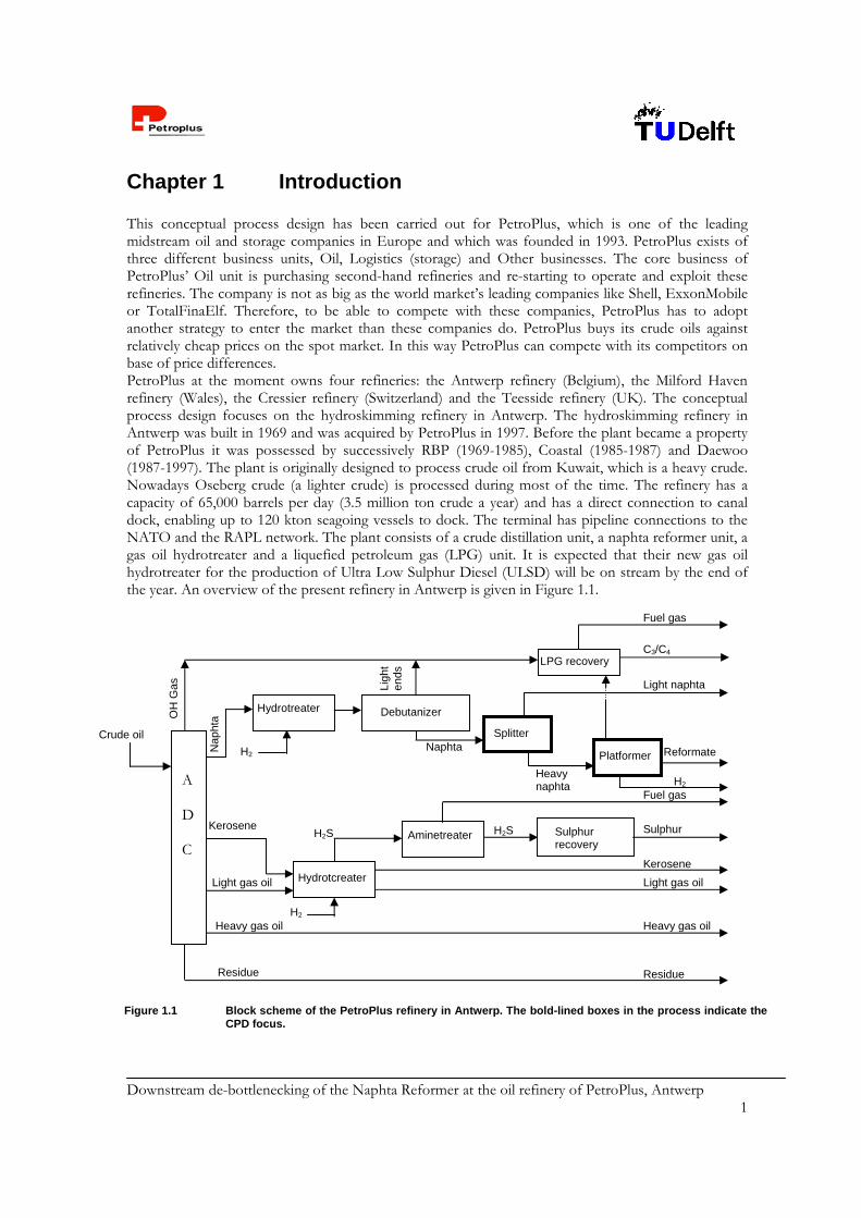
Chapter 1 Introduction This conceptual process design has been carried out for PetroPlus, which is one of the leading midstream oil and storage companies in Europe and which was founded in 1993. PetroPlus exists of three different business units, Oil, Logistics (storage) and Other businesses. The core business of PetroPlus’ Oil unit is purchasing second-hand refineries and re-starting to operate and exploit these refineries. The company is not as big as the world market’s leading companies like Shell, ExxonMobile or TotalFinaElf. Therefore, to be able to compete with these companies, PetroPlus has to adopt another strategy to enter the market than these companies do. PetroPlus buys its crude oils against relatively cheap prices on the spot market. In this way PetroPlus can compete with its competitors on base of price differences. PetroPlus at the moment owns four refineries: the Antwerp refinery (Belgium), the Milford Haven refinery (Wales), the Cressier refinery (Switzerland) and the Teesside refinery (UK). The conceptual process design focuses on the hydroskimming refinery in Antwerp. The hydroskimming refinery in Antwerp was built in 1969 and was acquired by PetroPlus in 1997. Before the plant became a property of PetroPlus it was possessed by successively RBP (1969-1985), Coastal (1985-1987) and Daewoo (1987-1997). The plant is originally designed to process crude oil from Kuwait, which is a heavy crude. Nowadays Oseberg crude (a lighter crude) is processed during most of the time. The refinery has a capacity of 65,000 barrels per day (3.5 million ton crude a year) and has a direct connection to canal dock, enabling up to 120 kton seagoing vessels to dock. The terminal has pipeline connections to the NATO and the RAPL network. The plant consists of a crude distillation unit, a naphta reformer unit, a gas oil hydrotreater and a liquefied petroleum gas (LPG) unit. It is expected that their new gas oil hydrotreater for the production of Ultra Low Sulphur Diesel (ULSD) will be on stream by the end of the year. An overview of the present refinery in Antwerp is given in Figure 1.1.
A D C
Crude oil
OH
Gas
Nap
hta
Kerosene
Light gas oil
Heavy gas oil Heavy gas oil
Residue Residue
Hydrotcreater
H2
Kerosene
Light gas oil
H2S Aminetreater
Fuel gas
H2S
Sulphur recovery
Sulphur
Hydrotreater
H2
Debutanizer
Naphta
Ligh
t en
ds LPG recovery
Fuel gas
C3/C4
Splitter
Light naphta
Platformer
Heavy naphta H2
Reformate
Figure 1.1 Block scheme of the PetroPlus refinery in Antwerp. The bold-lined boxes in the process indicate the CPD focus.

Downstream de-bottlenecking of the Naphta Reformer at the oil refinery of PetroPlus, Antwerp 2
As the block scheme of Figure 1.1 shows the following products are produced: LPG Naphta Reformate Kero Jet fuel ULSD Fuel Oils The products are listed in increasing molecular weight. LPG is used are fuel for automotives. Naphta is feedstock for polyethylene production. Kero is sold as domestic fuel oil. Jet fuel is sold to aviation industry. ULSD is used as fuel for heavier automotives. The fuel oils are sold to several companies, which use it as fuel for ships. PetroPlus does not have any kind of long-term trading deals with other companies. Prices of the different products are listed in Appendix 10. For the conceptual process design (CPD) the reformate stream is regarded in more detail. It is sold to companies as blending compound for the production of gasoline. At present the reformate stream has a 1.5 vol% benzene content, whereas legislation demands a benzene content of 1 vol%. The goal of the CPD is to find a solution to reduce the benzene content to 1 vol%. At present the naphta splitter (NS) is operated at a 50/50 Light Desulphurized Naphta/Heavy Desulphurized Naphta (LDN/HDN) ratio, due to benzene restrictions in the past. At this NS ratio a benzene content of 1.5 vol% is achieved [1]. However, PetroPlus wants to reset the split factor to the originally designed ratio of 30/70 LDN/HDN for economic reasons. HDN is the feedstock for reformate. First a relatively higher production of reformate with respect to LDN is wanted because of a higher economic value. Secondly, a higher throughput can be processed, because at the moment the throughput is limited by the capacity of the LDN units. As a consequence of the 30/70 split the reformate stream has a benzene content of 3.84 vol%. The focus of this project is to find a solution that gives a benzene content of 1 vol% in the reformate stream, while operating the NS at a 30/70 LDN/HDN ratio. In Chapter 2 various process options are mentioned and discussed. The final concept of the design is hydrogenation of benzene after splitting the reformate stream. This process is referred as Debenzenizer. It consists of a splitting unit, referred as Splitter and a hydrogenation unit, referred as Hydrogenator.The main reasons for selecting this option are the following: The 1 vol% benzene specification is reached; Only part of the total reformate stream is treated, this means both energy and cost savings; The process is flexible since also other aromatic hydrocarbons like toluene and xylene can be
treated and the throughput can even be higher than demanded; The RON is maintained at the desired value, while the total product stream is only slightly
decreased. A block scheme of the Debenzenizer is represented in Figure 2.1. The benzene in the split stream is converted into cyclohexane. The reactor effluent is partly recycled and partly blended into the bottom stream. Also a part of the top is blended into the bottom till a RON of 99.5 is reached. In brief, expansion of the plant with the Debenzenizer unit will lead to a reformate stream that meets the demanded benzene specification, which means that the product will have a higher market value, than the actual product-stream. The Debenzenizer unit shows similarities with the IFP Benfree™ process, which is patented. The patent in Appendix 33 describes the general process of the selective
Downstream de-bottlenecking of the Naphta Reformer at the oil refinery of PetroPlus, Antwerp 3
hydrogenation of aromatics, patented by IFP. For more detailed description of the Benfree™ process the reader is referred to [2]. On account of small differences it might be possible to avoid patent costs. A difficulty in designing the Debenzenizer was the choice of the right kinetics for the hydrogenation reaction. Several mechanisms of reaction have been published [3, 4, 5, 6]. The selection of the mechanism is based on the applicability to the conditions as applied in the Debenzenizer. Details are described in Chapter 2. Another design topic is the cooling of the Hydrogenator. The reaction in the Hydrogenator is exothermic and has a reaction heat of –205 kJ/mole. To deal with the heat production, the reactor is cooled in two ways. Firstly by recycling a part of the reactor effluent and quenching it into the reactor, secondly by installing a cooling jacket. Except for catalyst abrasion the Debenzenizer does not create extra waste streams. As already mentioned, only part of the total reformate stream is treated. This avoids the needless wasting of energy. HAZOP and FE&I analyses are applied to indicate the safety of the Debenzenizer. These safety analyses are shown in Chapter 10.
Downstream de-bottlenecking of the Naphta Reformer at the oil refinery of PetroPlus, Antwerp 4
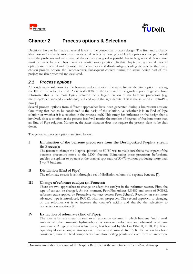
Chapter 2 Process options & Selection Decisions have to be made at several levels in the conceptual process design. The first and probably also most influential decision that has to be taken is on a more general level: a process concept that will solve the problems and will answer all the demands as good as possible has to be generated. A selection must be made between batch wise or continuous operation. In this chapter all generated process options are presented and discussed with advantages and disadvantages, leading stepwise to the finally chosen process option, the Debenzenizer. Subsequent choices during the actual design part of this project are also presented and evaluated.
2.1 Process options Although many solutions for the benzene reduction exist, the most frequently cited option is raising the IBP of the reformer feed. As typically 80% of the benzene in the gasoline pool originates from reformate, this is the most logical solution. So a larger fraction of the benzene precursors (e.g. methylcyclopentane and cyclohexane) will end up in the light naphta. This is the situation at PetroPlus now [1]. Several process options from different approaches have been generated during a brainstorm session. One thing that had to be considered is the basis of the solution, i.e. whether it is an End of Pipe solution or whether it is a solution in the process itself. This surely has influence on the design that is involved, since a solution in the process itself will restrict the number of degrees of freedom more than an End of Pipe solution. Moreover, the latter situation does not require the present plant to be shut down. The generated process options are listed below. I Elimination of the benzene precursors from the Desulpurized Naphta stream
(in Process): The reason to change the Naphta split ratio to 50/50 was to make sure that a major part of the benzene precursors move to the LDN fraction. Eliminating these precursors beforehand enables the splitter to operate at the original split ratio of 30/70 without producing more than 1 vol% benzene.
II Distillation (End of Pipe): The reformate stream is sent through a set of distillation columns to separate benzene [7].
III Change of reformer catalyst (in Process): There are two approaches to change or adapt the catalyst in the reformer reactor. First, the type of cat can be changed. At this moment, PetroPlus utilizes RG482 and some of RG582, reformer cats supplied by Procatalyse (contact person Peter Scherp). Recently, an even more advanced type is introduced, RG682, with new properties. The second approach to changing of the reformer cat is to increase the catalyst’s acidity and thereby the selectivity to isomerization reactions [7].
IV Extraction of reformate (End of Pipe): The total reformate stream is sent to an extraction column, in which benzene (and a small amount of other aromatic hydrocarbons) is extracted selectively and obtained as a pure component. A typical solvent is Sulfolane, first licensed by Shell in 1962 [8, 9, 10, 11]. It is a liquid-liquid extraction, at atmospheric pressure and around 463.15 K. Extraction has been considered, since the feed components have close boiling points and even form an azeotropic

Downstream de-bottlenecking of the Naphta Reformer at the oil refinery of PetroPlus, Antwerp 5
mixture. Although extraction leads to pure benzene recovery this is not one of the design objectives.
V Extraction after splitting off the benzene-rich fraction (End of Pipe): The reformate stream is sent to a splitter column, in which a benzene-rich fraction is separated. This stream is further extracted, using the Sulfolane process.
VI Isomerization, combined with a molar sieve (End of Pipe): Part (C5 and C6) of the LDN from the Naphta Splitter is sent to an isomerizing unit. Here the linear alkanes are converted into branched isomers, which have a higher RON. The mixture is then sent to a molecular sieve, where the linear molecules are physically separated from the branched ones. Pressure is reduced to release the adsorbed molecules. The branched molecules are blended with the final product and the linear alkanes are recycled for isomerization. This process resembles the UOP TIP process and is an advanced version of Shell Hysomer, the Penex and the Isosiv process [7, 9, 12, 13, 14] and a possible catalyst for the isomerization reaction is the Akzo Nobel Total-2.
VII Selective hydrogenation of benzene after splitting the reformate stream (End of Pipe): The reformate stream is sent to a splitter column, which separates benzene with its azeotropes [15] selectively from the reformate stream. This is executed by designing a draw-off tap at the column height where boiling of benzene occurs. This tap stream is subsequently sent to a hydrogenation reactor, where benzene is transformed into cyclohexane. The effluent of this reactor is recycled and partly mixed with the top stream. In this situation, the final benzene concentration of the product will be as low as 0.59 vol%. This End of Pipe installation for treatment of the reformate, i.e. the combination of the splitter and the hydrogenation reactor with additional equipment will be called the Debenzenizer. Hydrogenation after splitting comes down to the IFP Benfree process [2]. Possible license cost must be concerned,
VIII Isomerization combined with a molar sieve and a splitter/hydrogenation section (End of Pipe): A fraction of the LDN is isomerized, which is already explained, and the HDN is still sent to the reformer. After reaction the reformate passes a splitter column and benzene is separated. This benzene rich stream is then hydrogenated into cyclohexane. The product streams of hydrogenation and isomerization are blended. This option is a combination of isomerization (TIP, Hysomer, Isosiv) and hydrogenation (Debenzenizer), which will enhance product quality to a large extent. However, this will increase the investment costs as well. This is logical, since more license costs are involved and besides two additional equipment sections must be designed and installed.
These possible process options have been evaluated and their main advantages and disadvantages are briefly summarized in Table 2.1. The numbers of the options correspond with the text.

Downstream de-bottlenecking of the Naphta Reformer at the oil refinery of PetroPlus, Antwerp 6
Table 2.1 Summary of the characteristics of the generated process options Option # Benzene
spec Naphta
Split ratio of 30/70
RON 99.5
License costs 1)
Effect of stream
volume 2)
Comments
I + + – + – – II + + – + – Equipment and Space III – – + + – Extra hydrogen
production IV + + – – – –V + + – – + –VI – – – – – Another way to enhance
RON is offered VII + + + Possibly + Reduction of aromatic
content is possible VIII + + + – + Expensive process.
Future? 1) A +-sign stands for a positive effect, i.e. probably no license costs. 2) A +-sign means that the volume to be treated is relatively small compared to other options. Another option was to use microorganisms or enzymes to convert benzene. However, there were a number of drawbacks, which made this biotechnological approach be cancelled early. For instance, most enzymes work in aqueous media, or in a oil-water interface, which is not the case here. Although they can withstand high pressures (ranging from 4 to 5000 bara), they are not always high-temperature stable. More detailed process descriptions and argumentation for the process selection are given in Appendix 3 and block schemes of the rejected options are given in Appendix 4.
2.2 Selected process option For this project, option VII has been selected for further design, i.e. the Debenzenizer, in which the splitting of a benzene-rich stream is followed by hydrogenation into cyclohexane. It is for this reason that this process option deserves special attention. The overall reaction is: The H2 that is needed for the hydrogenation is produced in the reformer. Below, the advantages and disadvantages of the Debenzenizer are summarized. Advantages: The 1 vol% benzene spec is easily reached; benzene can even be hydrogenated for up to 99.9%,
according to Toppinen et al [5, 6]. Only part of the total reformate stream is treated, 6.01 instead of 50.6 ton/h. This means that
equipment can be sized smaller and less energy costs are involved. The process is flexible in the sense that, if necessary, it has the option to treat other aromatic
hydrocarbons, like toluene and xylene as well [5, 6]. In that case the draw off tap has to be
+ 3H2 H0298 = -205.4 [kJ/mol]
benzene cyclohexane

Downstream de-bottlenecking of the Naphta Reformer at the oil refinery of PetroPlus, Antwerp 7
reconsidered. This is attractive in the case that future legislation will be further sharpened with respect to the total aromatics content.
The RON is maintained at 99.5, while the decrease of reformate flow is partly compensated by selling the fuel gas over the top. Compared to for example extraction, the decrease of reformate stream is less. Besides, all streams can be sold and clients are already acquired via the current network.
The Naphta Splitter is operated at the desired LDN/HDN split ratio of 30/70 without the problem of excess benzene content. The surplus of benzene precursors at this ratio is not a bottleneck anymore, since benzene is converted into cyclohexane. The result is that the total throughput of gasoline is increased, leading to higher earnings.
This option is an End of Pipe approach, thereby allowing more degrees of freedom for the total process. There is less interference with the current plant, which itself is already rather complex. Further, it is not needed to shut down the current plant for a long while when integrating the selected option.
Disadvantages: Possibly license costs must be paid for the IFP BenfreeTM process, see Appendix 33. However,
license costs are usually calculated as a lump sum, a part of the operating costs, so no dramatic effects should be expected,
Although benzene is toxic and so unwanted in gasoline, it is still a valuable product. With hydrogenation the benzene fraction is eliminated. This means that benzene is not recovered, but converted into the ‘inferior’ cyclohexane, with lower RON. However, the total RON will be on spec and the benzene spec is met. The rest stream can be sold as LDN.
As becomes clear from these considerations, the Debenzenizer can fulfill all demands that were set by the principal: RON = 99.5 Benzene content 1 vol% Naphta splitter ratio = 30/70 (LDN/HDN) Besides, it provides additional flexibility with respect to the feed composition and magnitude; possible future legislation might force industry to eliminate other aromatic compounds from gasoline to a certain extent. The selected option is able to handle these changes, without drastic changes in the process. The relatively small stream that has to be treated is an extra benefit. The two drawbacks as mentioned are manageable and not severe. Unfortunately, it is not yet clear whether license costs do have to be paid or not, but as already said, its effect will not be dramatic. The conversion of benzene into cyclohexane results in a relatively lower production of reformate, but otherwise the reformate would not meet the specifications, either on RON or benzene content. The reformate loss is quite small: only 2.35 wt% of the reformate intake <201> in the 30/70 case cannot be sold as reformate, but as LDN. 2.2.1 Mode of operation The Debenzenizer will be operated continuously, since the feedstock is also supplied continuously and the current plant in Antwerp operates continuously. Batch operation would require additional filling, cleaning and emptying efforts, which are not necessary, but only redundant in this case. There is no reason to choose a batch wise operation. This is further grounded when regarding the feedstock of 6.01 ton/h. According to Douglas [166], batch operation is discarded when the expected production rate exceeds 107 lb/yr ~ 0.56 ton/h. The reactor is thereby not designed to be multipurpose (which would be a criterion for selecting batch operation) and the product market lifetime is not short: gasoline is not a seasonal product and it can be stored for a long time before use, without significantly losing financial value. This all supports the choice of continuous operation. The last considerations would be about

Downstream de-bottlenecking of the Naphta Reformer at the oil refinery of PetroPlus, Antwerp 8
scaling up. Batch operation is favored, when slurries have to be pumped around or when the reactants and products are rapidly fouling materials. These criteria do not hold in case of implementation of the Debenzenizer. According to this evaluation, continuous operation is selected. 2.2.2 Block scheme The process to be designed must be compatible with the current refinery. A block scheme of the present process is given in Figure 1.1 and the reformate stream from the Platformer is the Feed of the Debenzenizer, after it has passed a set of stabilizers to release C3 and C4 compounds. This is the starting point of the design and a block scheme of the Debenzenizer is presented in Figure 2.1. Next, the basis of the chosen process concept will be described step by step, but briefly. More detailed description is given in Chapter 5. The Feed of the Splitter column is the product stream of the Platformer, after passing a set of to
remove propane and butane. This Feed stream is separated into three main streams: the Top, the Bottom and the Split. It is
clear that the Top and the Bottom contain the lightest and the lowest components respectively. The Split is designed to remove a benzene–rich stream, such that one column will be sufficient for the necessary separation. This is realized by designing a draw-off tap at a stage between the Feed stage and the Top, where boiling of benzene occurs.
Figure 2.1 Block scheme of the Debenzenizer
HP represents a High Pressure Separator and operates at 20ºC and 23 bara.
LP represents a Low Pressure Separator and operates at 18ºC and 1 bara.
R-In 227,000 kt/a
Feed 405,000 kt/a
Effluent 252,200 kt/a
Reactor 25 bara ~125ºC
HP
LP
Splitter Column
1 bara 23-119ºC
Split 48,000 kt/a
Top 6,240 kt/a
HP-Vapor 21,800 kt/a
LP-Vapor 6,630 kt/a
Blend 395,530 kt/a
Bottom 288,000 kt/a
C-Rec 179,000 kt/a
C-Prod 44,770 kt/a
HP-Liq 230,400 kt/a
Fresh H2 25,200 kt/a
Top to Blend 62,760 kt/a
Total IN: 430,200 kt/a
Total OUT: 430,200 kt/a

Downstream de-bottlenecking of the Naphta Reformer at the oil refinery of PetroPlus, Antwerp 9
The streams that leave the Splitter all have their own destinations. The Top and the Bottom streams will be dealt with later. The Split stream will be hydrogenated, this means that benzene present in the stream is converted into cyclohexane by a catalytic reaction,
As can be seen from the block scheme in figure 2.1, the Split stream is mixed with a stream called C-Rec. This is a recycle stream of hydrocarbons, with low benzene content. Besides, hydrogen is also supplied from the existing hydrogen network at 25 barg. These streams together enter the reactor.
The catalyst that is used is a nickel catalyst on an alumina carrier. This catalyst is purchased at ICI Synetix and is called HTC400. The catalyst has a trilobe shape to enhance mass and heat transfer within the particle. Besides, trilobes have a relatively high mechanical strength. Nickel is a cheap metal and functions well in the hydrogenation of aromatic hydrocarbons,
Hydrogen has two main functions: at first, it is a reactant for the hydrogenation reaction and second, it will prevent the nickel catalyst from fast poisoning (coke formation) and deactivation.
The recycle hydrocarbon stream functions as a cold quench liquid. Cold quenching is needed, since the hydrogenation reaction is exothermic (rH = –205.4 kJ/mole). Since many factors, like catalyst stability and reaction kinetics are temperature dependent, the aim is to keep the reactor temperature below 425K. Moreover for some components the critical temperature is reached above 425K. Besides, a thermal runaway must be avoided. Liquids have much higher heat capacities than gases, and therefore the hydrocarbon mixture is a better quench medium than hydrogen. The ratio of recycle volume versus net effluent volume is 4.
Before the reaction mixture can be recycled, the stream must first release hydrogen, such that hydrogen is recovered. To recover the amount of hydrogen in the mixture for over 99%, two separators will be used. Since the solubility of hydrogen is proportional to the applied pressure, a logical approach is to operate the first separator at high pressure, and the latter at low pressure to remove the remaining. The hydrogen at high pressure is sent to the Naphta Hydrotreater (part of the current plant), while the low-pressure hydrogen is sold as hydrogen-rich fuel gas. One remark here is that at ambient pressure, the gas phase will partly consist of hydrocarbons, but this is not harmful for the product value. Hydrogen at high pressure is more valuable.
The net effluent stream (C-Prod) is mixed with the Bottom stream of the Splitter and with 91% of the Top stream. With this blending ratio, the benzene concentration is 0.59 vol% and the RON will be 99.5, when operating at a naphta split ratio of 30/70.
Downstream de-bottlenecking of the Naphta Reformer at the oil refinery of PetroPlus, Antwerp 10
Chapter 3 Basis of design
3.1 Description of the design As already mentioned in the introduction of this report, the focus of this project is the reduction of the benzene content in the reformate stream produced by the PetroPlus refinery in Antwerp. The present reformate contains 1.5 vol% of benzene. The goal of the project is to design a process which treats the reformate stream in such way that benzene is reduced to at most 1 vol%, the maximal legally permitted content. Besides PetroPlus wants to change the HDN/LDN ratio of the NS back from 50/50 to 30/70. As a result more HDN is sent to the Platformer, and so more reformate is produced. In that case more benzene precursors are discharged with the HDN stream and thus more benzene will be present in the reformate stream. For several reasons (as explained in chapter 2 and summarized in the following section) selective hydrogenation of benzene after splitting the reformate stream is chosen as the best option. The reformate is fed into a column, the fraction containing the benzene is separated as a side stream and sent to a reaction section. The benzene is hydrogenated to cyclohexane in a trickle-bed-reactor. One of the main advantages of this process is that after splitting off the benzene rich fraction, only a part of the reformate is hydrogenated in the reactor. This makes the reaction section small and relatively well controllable.
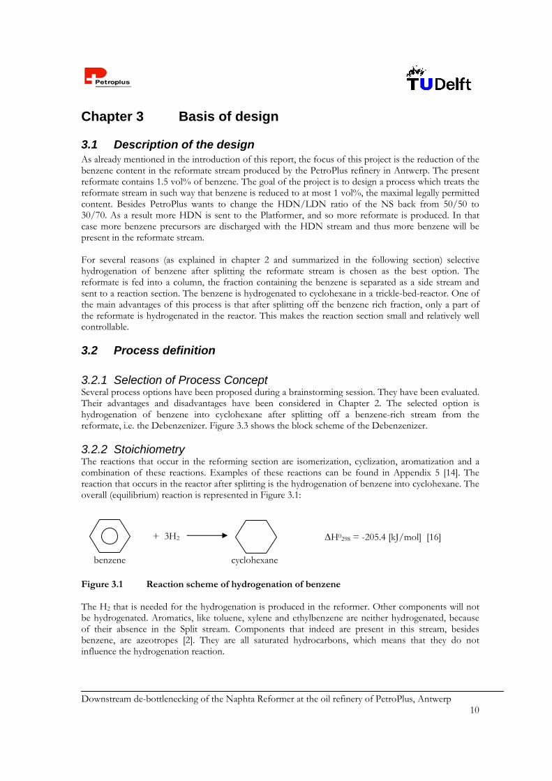
3.2 Process definition 3.2.1 Selection of Process Concept Several process options have been proposed during a brainstorming session. They have been evaluated. Their advantages and disadvantages have been considered in Chapter 2. The selected option is hydrogenation of benzene into cyclohexane after splitting off a benzene-rich stream from the reformate, i.e. the Debenzenizer. Figure 3.3 shows the block scheme of the Debenzenizer. 3.2.2 Stoichiometry The reactions that occur in the reforming section are isomerization, cyclization, aromatization and a combination of these reactions. Examples of these reactions can be found in Appendix 5 [14]. The reaction that occurs in the reactor after splitting is the hydrogenation of benzene into cyclohexane. The overall (equilibrium) reaction is represented in Figure 3.1: Figure 3.1 Reaction scheme of hydrogenation of benzene The H2 that is needed for the hydrogenation is produced in the reformer. Other components will not be hydrogenated. Aromatics, like toluene, xylene and ethylbenzene are neither hydrogenated, because of their absence in the Split stream. Components that indeed are present in this stream, besides benzene, are azeotropes [2]. They are all saturated hydrocarbons, which means that they do not influence the hydrogenation reaction.
+ 3H2 H0298 = -205.4 [kJ/mol] [16]
benzene cyclohexane
Downstream de-bottlenecking of the Naphta Reformer at the oil refinery of PetroPlus, Antwerp 11
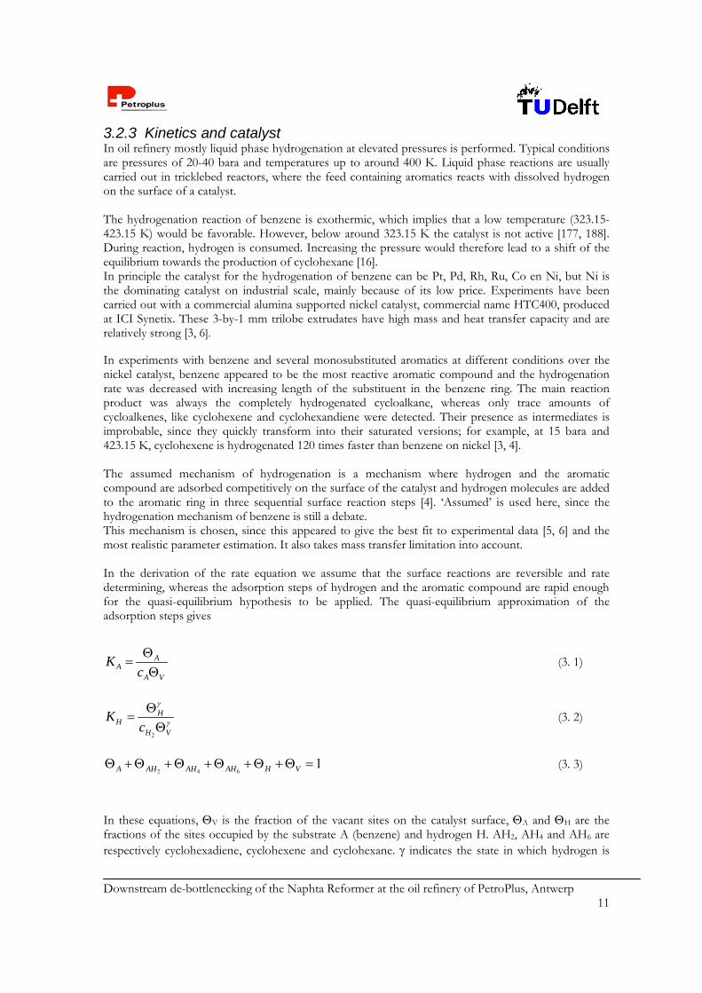
3.2.3 Kinetics and catalyst In oil refinery mostly liquid phase hydrogenation at elevated pressures is performed. Typical conditions are pressures of 20-40 bara and temperatures up to around 400 K. Liquid phase reactions are usually carried out in tricklebed reactors, where the feed containing aromatics reacts with dissolved hydrogen on the surface of a catalyst. The hydrogenation reaction of benzene is exothermic, which implies that a low temperature (323.15-423.15 K) would be favorable. However, below around 323.15 K the catalyst is not active [177, 188]. During reaction, hydrogen is consumed. Increasing the pressure would therefore lead to a shift of the equilibrium towards the production of cyclohexane [16]. In principle the catalyst for the hydrogenation of benzene can be Pt, Pd, Rh, Ru, Co en Ni, but Ni is the dominating catalyst on industrial scale, mainly because of its low price. Experiments have been carried out with a commercial alumina supported nickel catalyst, commercial name HTC400, produced at ICI Synetix. These 3-by-1 mm trilobe extrudates have high mass and heat transfer capacity and are relatively strong [3, 6]. In experiments with benzene and several monosubstituted aromatics at different conditions over the nickel catalyst, benzene appeared to be the most reactive aromatic compound and the hydrogenation rate was decreased with increasing length of the substituent in the benzene ring. The main reaction product was always the completely hydrogenated cycloalkane, whereas only trace amounts of cycloalkenes, like cyclohexene and cyclohexandiene were detected. Their presence as intermediates is improbable, since they quickly transform into their saturated versions; for example, at 15 bara and 423.15 K, cyclohexene is hydrogenated 120 times faster than benzene on nickel [3, 4]. The assumed mechanism of hydrogenation is a mechanism where hydrogen and the aromatic compound are adsorbed competitively on the surface of the catalyst and hydrogen molecules are added to the aromatic ring in three sequential surface reaction steps [4]. ‘Assumed’ is used here, since the hydrogenation mechanism of benzene is still a debate. This mechanism is chosen, since this appeared to give the best fit to experimental data [5, 6] and the most realistic parameter estimation. It also takes mass transfer limitation into account. In the derivation of the rate equation we assume that the surface reactions are reversible and rate determining, whereas the adsorption steps of hydrogen and the aromatic compound are rapid enough for the quasi-equilibrium hypothesis to be applied. The quasi-equilibrium approximation of the adsorption steps gives
AA
A V
Kc
(3. 1)
2
HH
H V
Kc
(3. 2)
2 4 61A AH AH AH H V (3. 3)
In these equations, V is the fraction of the vacant sites on the catalyst surface, A and H are the fractions of the sites occupied by the substrate A (benzene) and hydrogen H. AH2, AH4 and AH6 are respectively cyclohexadiene, cyclohexene and cyclohexane. indicates the state in which hydrogen is
Downstream de-bottlenecking of the Naphta Reformer at the oil refinery of PetroPlus, Antwerp 12
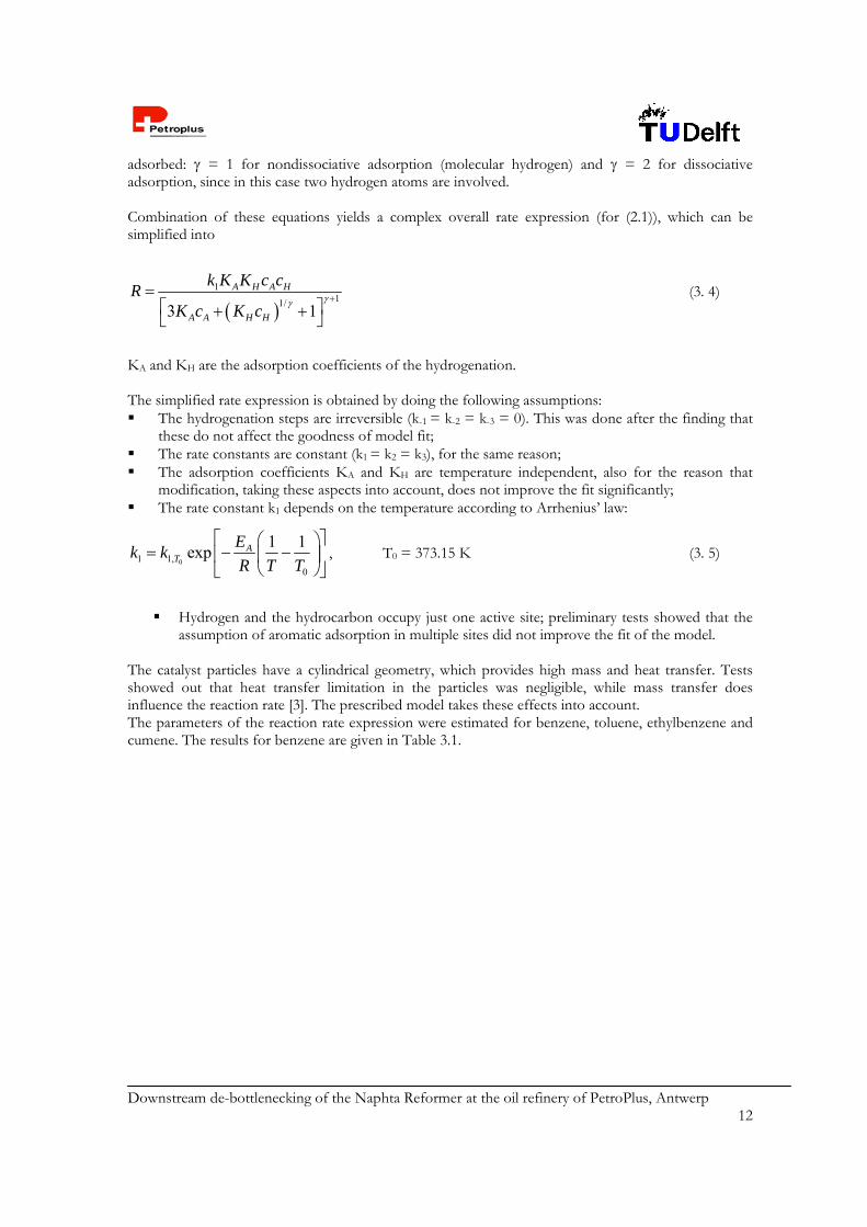
adsorbed: = 1 for nondissociative adsorption (molecular hydrogen) and = 2 for dissociative adsorption, since in this case two hydrogen atoms are involved. Combination of these equations yields a complex overall rate expression (for (2.1)), which can be simplified into
1
11/3 1
A H A H
A A H H
k K K c cR
K c K c
(3. 4)
KA and KH are the adsorption coefficients of the hydrogenation. The simplified rate expression is obtained by doing the following assumptions: The hydrogenation steps are irreversible (k-1 = k-2 = k-3 = 0). This was done after the finding that
these do not affect the goodness of model fit; The rate constants are constant (k1 = k2 = k3), for the same reason; The adsorption coefficients KA and KH are temperature independent, also for the reason that
modification, taking these aspects into account, does not improve the fit significantly; The rate constant k1 depends on the temperature according to Arrhenius’ law:
01 1,0
1 1exp A
T
Ek k
R T T
, T0 = 373.15 K (3. 5)
Hydrogen and the hydrocarbon occupy just one active site; preliminary tests showed that the
assumption of aromatic adsorption in multiple sites did not improve the fit of the model. The catalyst particles have a cylindrical geometry, which provides high mass and heat transfer. Tests showed out that heat transfer limitation in the particles was negligible, while mass transfer does influence the reaction rate [3]. The prescribed model takes these effects into account. The parameters of the reaction rate expression were estimated for benzene, toluene, ethylbenzene and cumene. The results for benzene are given in Table 3.1.
Downstream de-bottlenecking of the Naphta Reformer at the oil refinery of PetroPlus, Antwerp 13
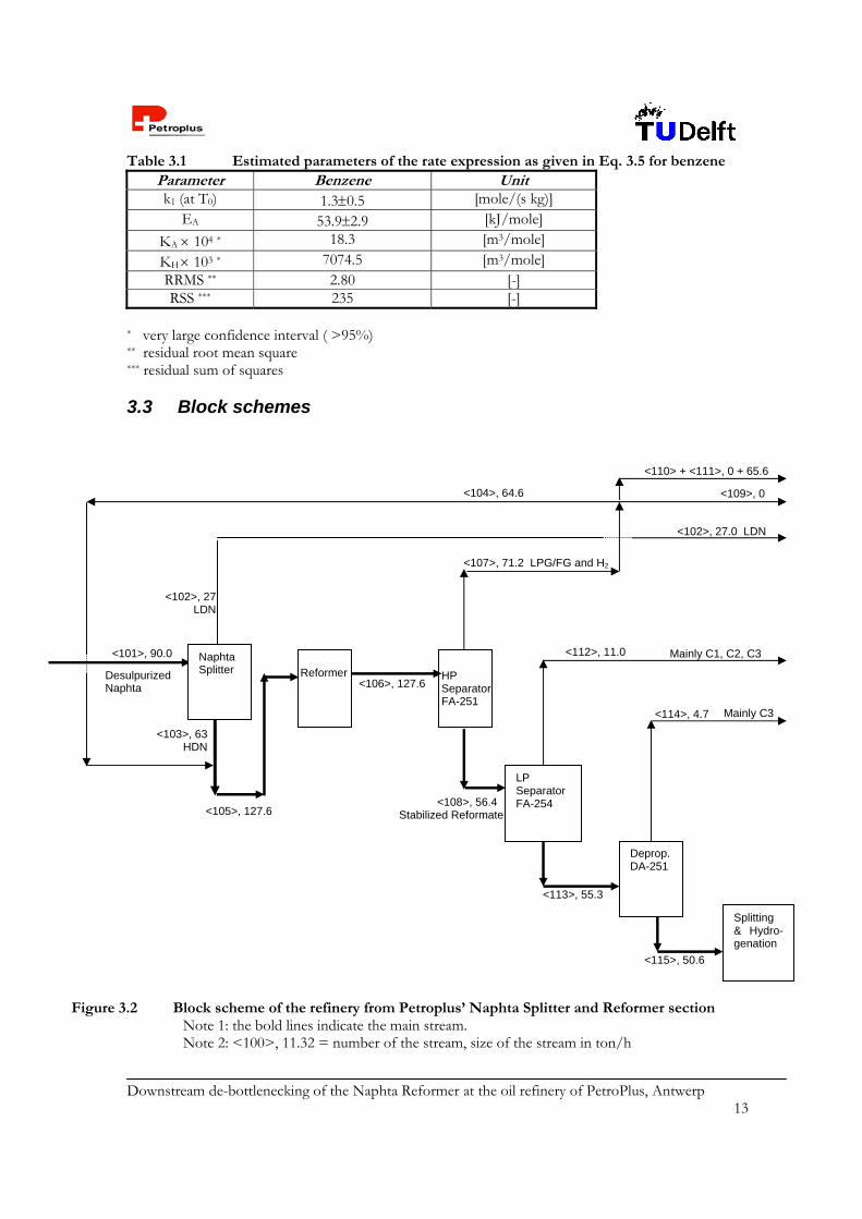
Table 3.1 Estimated parameters of the rate expression as given in Eq. 3.5 for benzene Parameter Benzene Unitk1 (at T0) 1.30.5 [mole/(s kg)]
EA 53.92.9 [kJ/mole]
KA 104 * 18.3 [m3/mole]
KH 103 * 7074.5 [m3/mole] RRMS ** 2.80 [-] RSS *** 235 [-]
* very large confidence interval ( >95%) ** residual root mean square *** residual sum of squares
3.3 Block schemes
Mainly C3
<109>, 0
Figure 3.2 Block scheme of the refinery from Petroplus’ Naphta Splitter and Reformer sectionNote 1: the bold lines indicate the main stream. Note 2: <100>, 11.32 = number of the stream, size of the stream in ton/h
Desulpurized Naphta
<102>, 27.0 LDN
Reformer HP Separator FA-251
Splitting & Hydro-genation
Naphta Splitter
<103>, 63 HDN
<104>, 64.6
<105>, 127.6
<106>, 127.6
<107>, 71.2 LPG/FG and H2
<108>, 56.4 Stabilized Reformate
LP Separator FA-254
<113>, 55.3
<112>, 11.0
Deprop. DA-251
<114>, 4.7
<115>, 50.6
Mainly C1, C2, C3
<102>, 27 LDN
<101>, 90.0
<110> + <111>, 0 + 65.6
Downstream de-bottlenecking of the Naphta Reformer at the oil refinery of PetroPlus, Antwerp 14
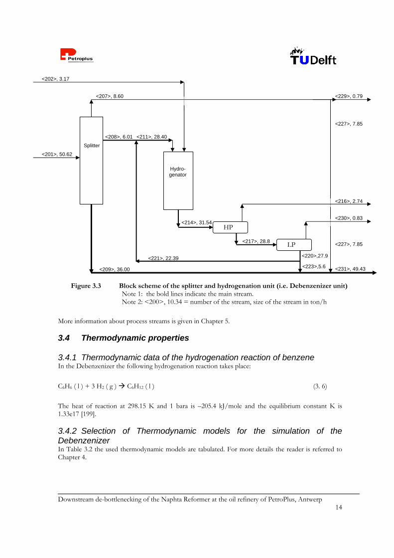
More information about process streams is given in Chapter 5.
3.4 Thermodynamic properties 3.4.1 Thermodynamic data of the hydrogenation reaction of benzene In the Debenzenizer the following hydrogenation reaction takes place:
C6H6 ( l ) + 3 H2 ( g ) C6H12 ( l ) (3. 6)
The heat of reaction at 298.15 K and 1 bara is –205.4 kJ/mole and the equilibrium constant K is 1.33e17 [199]. 3.4.2 Selection of Thermodynamic models for the simulation of the Debenzenizer In Table 3.2 the used thermodynamic models are tabulated. For more details the reader is referred to Chapter 4.
<201>, 50.62
Figure 3.3 Block scheme of the splitter and hydrogenation unit (i.e. Debenzenizer unit) Note 1: the bold lines indicate the main stream. Note 2: <200>, 10.34 = number of the stream, size of the stream in ton/h
<202>, 3.17
Splitter
Hydro- genator
HP
LP
<208>, 6.01
<207>, 8.60
<209>, 36.00
<221>, 22.39
<211>, 28.40
<214>, 31.54
<216>, 2.74
<217>, 28.8
<230>, 0.83
<229>, 0.79
<231>, 49.43
<227>, 7.85
<220>,27.9
<223>,5.6
<227>, 7.85

Downstream de-bottlenecking of the Naphta Reformer at the oil refinery of PetroPlus, Antwerp 15
Table 3.2 Survey of used thermodynamic models Block number Description Thermodynamic model
C201 Splitter NRTL-RK R201 Hydrogenator RK-SOAVE P203 Pump NRTL T201 Valve NRTL-RK K201 Compressor RK-SOAVE E201 Condenser NRTL-RK E202 Reboiler NRTL-RK E203 Heat exchanger NRTL-RK E204 Cooler RK-SOAVE E205 Cooler NRTL-RK V202 High pressure separator RK-SOAVE V203 Low pressure separator RK-SOAVE
3.5 Pure component properties In Appendix 6 the pure component properties are tabulated.
3.6 Basic Assumptions This section describes the basic assumptions made for the design of a benzene splitter, with a successive hydrogenation step. This EoP solution reduces the benzene content to zero and is designed for the maximum production of reformate. This is when the NS is set on split factor LDN/HDN of 30/70. 3.6.1 Plant Capacity In section 3.3 Figure 3.2 and 3.3 show a block scheme of the total treatment of the naphta fraction. In Table 3.3 gives an overview of intake and product streams. From economic point of view the naphta section is taken within the battery limit. By de-bottlenecking the benzene content, more reformate with respect to LDN is produced and a higher throughput is achieved. For the CPD only the Debenzenizer is considered. The annual production is based on 8000 hours production/a. The economical plant life is 27 years, indicated by [20]. Main streams Naphta intake <101> = 90.0 ton/h = 720 kton/a
NS split factor = 30/ 70 HDN/ LDN Reformate output with 4 wt% benzene, <115> = 50.6 ton/h = 405 kton/a Reformate output with < 1.0 wt% benzene, <201> = 46.9 ton/h = 375 kton/a The reasons for difference in mass flow between stream <115> and stream <201> are:
1. Extra C3 en C4 are taken out of the reformate before the intake of the Debenzenizer. This is done to enhance the operation of the Splitter.
2. Some of the reformate hydrocarbons leave the BL with the HP and LP Vapor discharge However the design of the Debenzenizer is based of on a reformate intake of 50.6 ton/h. The economic evaluation is based on 46.9 ton/h reformate intake.
Downstream de-bottlenecking of the Naphta Reformer at the oil refinery of PetroPlus, Antwerp 16
3.6.2 Location The Debenzenizer – unit is placed at PetroPlus Refinery in Antwerp (Belgium). Appendix 7 shows the map of the site. The Debenzenizer consists of a splitter and a hydrogenation reactor) and is assumed not to take in much space. Indeed, if process intensification is possible, the unit even requires less space. PetroPlus Antwerp is located in an industrial area, bordering on sites of the companies ExxonMobil , TotalFinaElf and NYNAS, a bitumen plant. 3.6.3 Battery Limit The battery limit for the CPD concern the new unit, the Debenzenizer. INSIDE: Benzene Splitter, Hydrogenator and 2 Flash drums OUTSIDE: ADC, NS, Platformer, Desulphurizer-units and recovery units other streams from
ADC. In other words, the intake starts at the reformate stream after stabilizers <201> and a fresh hydrogen feed <202>. The outtake of the battery limit consists of stream numbers <216>, <229>, <230> and <231>. From economic point of view the battery limit is taken from the intake for the NS <101> and Hydrogen <202> to the resulting products streams, <102>, <109>, <111>, <112>, <114>, <216>, <229>, <230> and <231>. The difference in economic margin is taken between before and after installing the Debenzenizer. For the present situation stream <229> and stream <231> are replaced by <115> and stream <202> is omitted. 3.6.4 In– and outgoing streams In Table 3.3 all streams for the economic battery limit are listed. The utility costs are specified only for the new equipment. The present situation is defined as the naphta section with NS at 50/ 50 LDN/ HDN and a throughput of 77 ton/h. Situation with Debenzenizer includes a split factor of the NS of 30/70 LDN/HDN with a throughput of 90 ton/h. Each of the mentioned streams is explained beneath the table. Calculations for utilities are outlined in Appendix 8.

Downstream de-bottlenecking of the Naphta Reformer at the oil refinery of PetroPlus, Antwerp 17
Table 3.3 Overview of change in streams and utilities by implementation of Debenzenizer Streams Present situation With Debenzenizer
Stream nr. [kg/h] [kton/a] Stream nr. [kg/h] [kton/a]
INTAKE – Feedstock Naphta from ADC <101> 77000 616 <101> 90020 720 H2 for HG - - - <202> 3154 25 OUTPUT – Products LDN <102> 38500
308 <102> <229>
27020 775 222
LPG <112> <114>
5134010 36
<112> <114>
1106 4711 47
Reformate <115> 30934 247 <231> 49440 395 Rich H2 fuel gas <111> 3043
24 <111> <216> <230>
6562 2742 816
81
Wastes - Others Present situation With Debenzenizer Utilities No extra utilities Fuel Oil - – (1)
Electricity - 808 103 kWh Cooling Water - 6.0 103 kton/a
Catalyst No extra cat [kg in Hydrogenator] Ni-cat (alumina) - 761(1) Additional energy requirements to heat the Platformer in the ‘30/70 situation’ are covered by heat integration with
the current units for Naphta Hydro Treating (NHT) and Hydro Desulphurizing (HDS). The reactions taking place in these units are all hydrotreating reactions, which have a common character of being moderate to highly exothermic. Moreover, the practical reaction temperatures in these units are 625-700 K and this creates a sufficient temperature difference for effective heat integration. [14]. Calculations on this subject have not been executed, since the NHT and the HDS are not covered within the battery limits of this design project.
Feedstock In the original design the reformer has a capacity of 120 m3/h. At the moment the throughput is approximately 55 m3/h. The unfavorable split factor of 50/50 LDN/ HDN reduces the benzene content in the reformate. On the other hand the recovery units for LDN run at maximum capacity and therefore is the bottleneck for the NS feed and the reformer throughput. PetroPlus wants to set the split factor back to 30/70 LDN/HDN, with a production of 90.0 m3/h HDN. 90 m3/h HDN corresponds with a 90.0 kton/h NS feed. Stream <115> has a flow rate of 50.6 ton/h and contains 4.34 wt% benzene. After removing the C3 and C4 components the remaining stream <201> is sent to the Debenzenizer. The flow rate is 48.0 ton/h. This is taken into account for economic calculations. However the design is based on a reformate intake of 50.6 ton/h for safety and flexibility reasons. Process chemicals Besides the catalyst and hydrogen no additional process chemicals are used.
Downstream de-bottlenecking of the Naphta Reformer at the oil refinery of PetroPlus, Antwerp 18
Products The product streams are: LPG <112>, <114> LDN <102>, <229> H2 rich Fuel Gas, <111>, <216>, <230> Reformate <231> Utilities For utilities the reader is referred to Appendix 9. Catalyst For catalyst the reader is referred to Section 5.1.2.
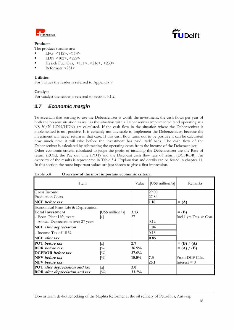
3.7 Economic margin To ascertain that starting to use the Debenzenizer is worth the investment, the cash flows per year of both the present situation as well as the situation with a Debenzenizer implemented (and operating at a NS 30/70 LDN/HDN) are calculated. If the cash flow in the situation where the Debenzenizer is implemented is not positive. It is certainly not advisable to implement the Debenzenizer, because the investment will never return in that case. If this cash flow turns out to be positive it can be calculated how much time it will take before the investment has paid itself back. The cash flow of the Debenzenizer is calculated by subtracting the operating costs from the income of the Debenzenizer. Other economic criteria calculated to judge the profit of installing the Debenzenizer are the Rate of return (ROR), the Pay out time (POT) and the Discount cash flow rate of return (DCFROR). An overview of the results is represented in Table 3.4. Explanation and details can be found in chapter 11. In this section the most important values are just shown to give a first impression. Table 3.4 Overview of the most important economic criteria.
Item Value [US$ million/a] Remarks
Gross Income 29.00 Production Costs 27.84 NCF before tax 1.16 = (A) Economical Plant Life & Depreciation Total Investment [US$ million/a] 3.13 = (B) – Econ. Plant Life, years: [a] 27 Incl.1 yrs Des. & Con.– Annual Depreciation over 27 years 0.12 NCF after depreciation 1.04 – Income Tax of 18 % 0.18 NCF after tax 0.85 POT before tax [a] 2.7 = (B) / (A) ROR before tax [%] 36.9% = (A) / (B) DCFROR before tax [%] 37.0% NPV before tax [%] 10.0% 7.3 From DCF Calc. NFV before tax 25.1 Interest = 0 POT after depreciation and tax [a] 3.0 ROR after depreciation and tax [%] 33.2%
Downstream de-bottlenecking of the Naphta Reformer at the oil refinery of PetroPlus, Antwerp 19
Chapter 4 Thermodynamic properties
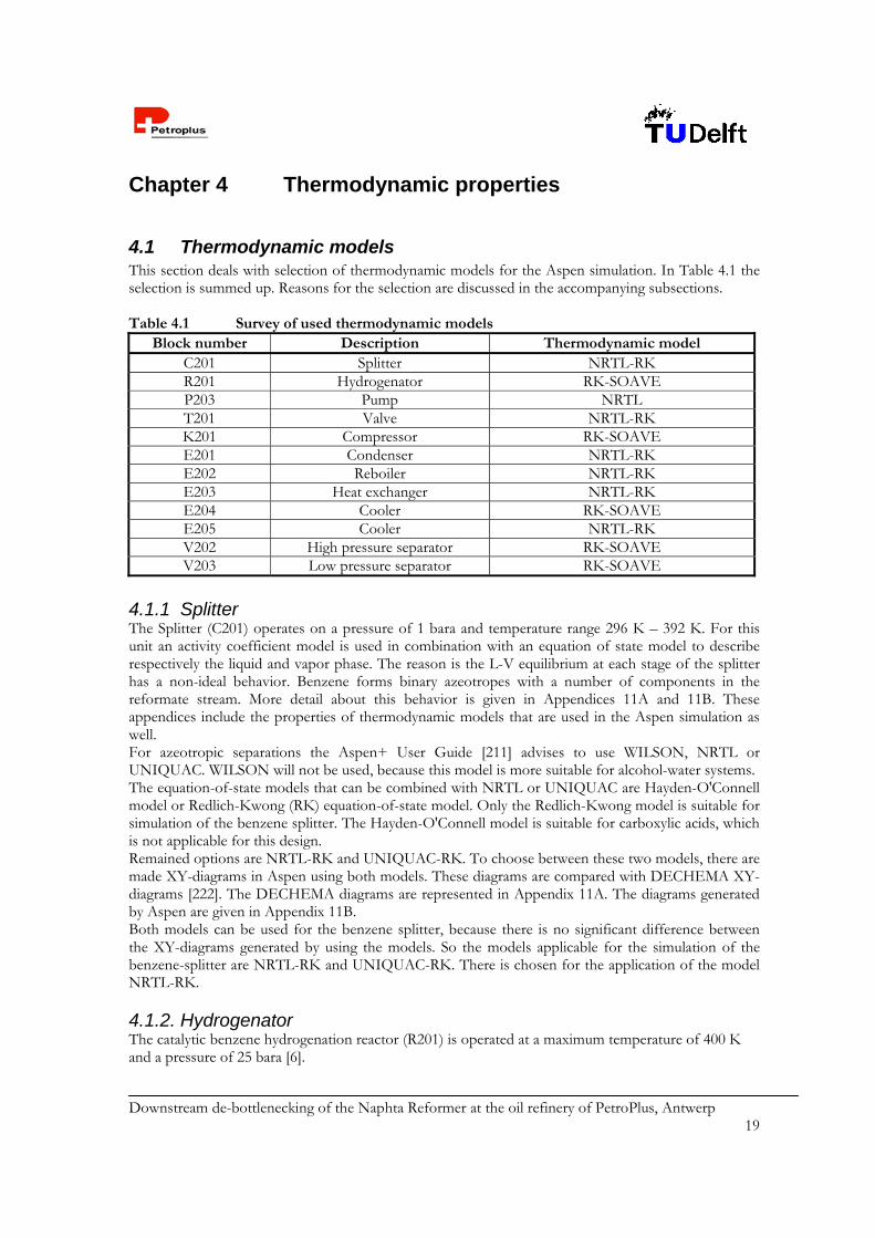
4.1 Thermodynamic models This section deals with selection of thermodynamic models for the Aspen simulation. In Table 4.1 the selection is summed up. Reasons for the selection are discussed in the accompanying subsections. Table 4.1 Survey of used thermodynamic models
Block number Description Thermodynamic model C201 Splitter NRTL-RK R201 Hydrogenator RK-SOAVE P203 Pump NRTL T201 Valve NRTL-RK K201 Compressor RK-SOAVE E201 Condenser NRTL-RK E202 Reboiler NRTL-RK E203 Heat exchanger NRTL-RK E204 Cooler RK-SOAVE E205 Cooler NRTL-RK V202 High pressure separator RK-SOAVE V203 Low pressure separator RK-SOAVE
4.1.1 Splitter The Splitter (C201) operates on a pressure of 1 bara and temperature range 296 K – 392 K. For this unit an activity coefficient model is used in combination with an equation of state model to describe respectively the liquid and vapor phase. The reason is the L-V equilibrium at each stage of the splitter has a non-ideal behavior. Benzene forms binary azeotropes with a number of components in the reformate stream. More detail about this behavior is given in Appendices 11A and 11B. These appendices include the properties of thermodynamic models that are used in the Aspen simulation as well. For azeotropic separations the Aspen+ User Guide [211] advises to use WILSON, NRTL or UNIQUAC. WILSON will not be used, because this model is more suitable for alcohol-water systems. The equation-of-state models that can be combined with NRTL or UNIQUAC are Hayden-O'Connell model or Redlich-Kwong (RK) equation-of-state model. Only the Redlich-Kwong model is suitable for simulation of the benzene splitter. The Hayden-O'Connell model is suitable for carboxylic acids, which is not applicable for this design. Remained options are NRTL-RK and UNIQUAC-RK. To choose between these two models, there are made XY-diagrams in Aspen using both models. These diagrams are compared with DECHEMA XY-diagrams [222]. The DECHEMA diagrams are represented in Appendix 11A. The diagrams generated by Aspen are given in Appendix 11B. Both models can be used for the benzene splitter, because there is no significant difference between the XY-diagrams generated by using the models. So the models applicable for the simulation of the benzene-splitter are NRTL-RK and UNIQUAC-RK. There is chosen for the application of the model NRTL-RK. 4.1.2. Hydrogenator The catalytic benzene hydrogenation reactor (R201) is operated at a maximum temperature of 400 K and a pressure of 25 bara [6].
Downstream de-bottlenecking of the Naphta Reformer at the oil refinery of PetroPlus, Antwerp 20
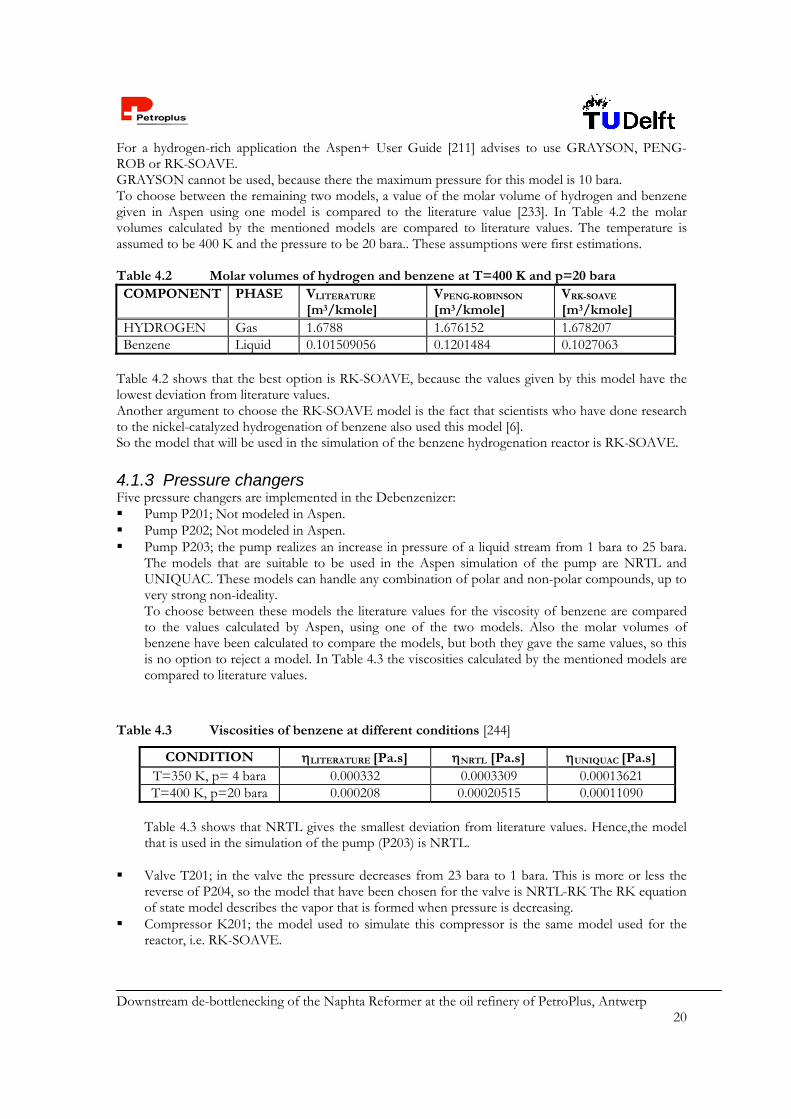
For a hydrogen-rich application the Aspen+ User Guide [211] advises to use GRAYSON, PENG-ROB or RK-SOAVE. GRAYSON cannot be used, because there the maximum pressure for this model is 10 bara. To choose between the remaining two models, a value of the molar volume of hydrogen and benzene given in Aspen using one model is compared to the literature value [233]. In Table 4.2 the molar volumes calculated by the mentioned models are compared to literature values. The temperature is assumed to be 400 K and the pressure to be 20 bara.. These assumptions were first estimations. Table 4.2 Molar volumes of hydrogen and benzene at T=400 K and p=20 bara COMPONENT PHASE VLITERATURE
[m3/kmole] VPENG-ROBINSON
[m3/kmole] VRK-SOAVE
[m3/kmole] HYDROGEN Gas 1.6788 1.676152 1.678207 Benzene Liquid 0.101509056 0.1201484 0.1027063
Table 4.2 shows that the best option is RK-SOAVE, because the values given by this model have the lowest deviation from literature values. Another argument to choose the RK-SOAVE model is the fact that scientists who have done research to the nickel-catalyzed hydrogenation of benzene also used this model [6]. So the model that will be used in the simulation of the benzene hydrogenation reactor is RK-SOAVE. 4.1.3 Pressure changers Five pressure changers are implemented in the Debenzenizer: Pump P201; Not modeled in Aspen. Pump P202; Not modeled in Aspen. Pump P203; the pump realizes an increase in pressure of a liquid stream from 1 bara to 25 bara.
The models that are suitable to be used in the Aspen simulation of the pump are NRTL and UNIQUAC. These models can handle any combination of polar and non-polar compounds, up to very strong non-ideality. To choose between these models the literature values for the viscosity of benzene are compared to the values calculated by Aspen, using one of the two models. Also the molar volumes of benzene have been calculated to compare the models, but both they gave the same values, so this is no option to reject a model. In Table 4.3 the viscosities calculated by the mentioned models are compared to literature values.
Table 4.3 Viscosities of benzene at different conditions [244]
CONDITION LITERATURE [Pa.s] NRTL [Pa.s] UNIQUAC [Pa.s] T=350 K, p= 4 bara 0.000332 0.0003309 0.00013621 T=400 K, p=20 bara 0.000208 0.00020515 0.00011090
Table 4.3 shows that NRTL gives the smallest deviation from literature values. Hence,the model that is used in the simulation of the pump (P203) is NRTL.
Valve T201; in the valve the pressure decreases from 23 bara to 1 bara. This is more or less the reverse of P204, so the model that have been chosen for the valve is NRTL-RK The RK equation of state model describes the vapor that is formed when pressure is decreasing.
Compressor K201; the model used to simulate this compressor is the same model used for the reactor, i.e. RK-SOAVE.

Downstream de-bottlenecking of the Naphta Reformer at the oil refinery of PetroPlus, Antwerp 21
4.1.4 Heat exchangers Five heat exchangers are implemented in the Debenzenizer: Condenser E201; this is a part of the column, so the model used to simulate the condenser is
NRTL-RK. Reboiler E202; this is also a part of the column, so the model used to simulate the condenser is
NRTL-RK. Heat exchanger E203; in this heat exchanger the bottom flow of the column <209> is cooled and
the recycle of the reactor <221> is heated. Because one of the heat exchanging flows come from the split column, the model used is NRTL-RK.
Cooler reactor effluent E204; in this cooler the reactor effluent is cooled from 399.33 K to 293.15 K. There is used the same model as for the reactor, i.e. RK-SOAVE.
Cooler bottom stream E205; in this cooler the bottom stream of the column is farther cooled. There is used the same model as for the split column, i.e. NRTL-RK.
4.1.5 Separators High Pressure separator V202; because the presence of hydrogen there will be made use of the
same model as the reactor. So the model that will be used is RK-SOAVE. The simulation gives the desired separation into liquid and vapor, so the model that has been used is justified.
Low-pressure separator V203; the same reason as for the high-pressure separator, the model that will be used in the Aspen simulation is RK-SOAVE.
4.2 Equilibrium data hydrogenation of benzene to cyclohexane In the hydrogenation reactor R201 the following hydrogenation reaction takes place:
C6H6 ( l ) + 3 H2 ( g ) C6H12 ( l ) (4. 1)
In Table 4.3 thermodynamic properties of components in this reaction are given. Other components in the stream to the hydrogenation reactor are saturated hydrocarbons, so the only component that will be hydrogenated is benzene. Table 4.3 Thermodynamic properties of components in hydrogenation reaction [199, 255]
COMPONENT FORMULA HF GF S CP
J/mole J/mole J(mole.K) J(mole.K) benzene (liquid) C6H6 (l) 4.90E+04 1.24E+05 173.4 137.86297
cyclohexane (liquid) C6H12 (l) -1.56E+05 2.67E+04 204.4 162.06909 hydrogen (gas) H2 (g) 0 0 130.68 28.836
The equilibrium constant of the reaction depends on de Gibbs free energy of the reaction. This relationship is described by the next relations.
lnG RT K (4. 2)
expG
KRT
(4. 3)
Downstream de-bottlenecking of the Naphta Reformer at the oil refinery of PetroPlus, Antwerp 22
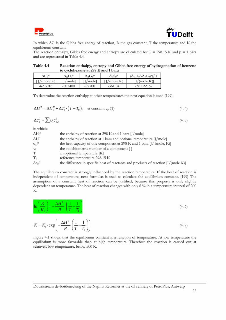
In which G is the Gibbs free energy of reaction, R the gas constant, T the temperature and K the equilibrium constant. The reaction enthalpy, Gibbs free energy and entropy are calculated for T = 298.15 K and p = 1 bara and are represented in Table 4.4. Table 4.4 Reaction enthalpy, entropy and Gibbs free energy of hydrogenation of benzene
to cyclohexane at 298 K and 1 bara
CP0 RH00 RG00 RS00 (RH00-RG00)/T [ J/(mole.K) [ J/mole] [ J/mole] [ J/(mole.K) [ J/(mole.K)]
-62.3018 -205400 -97700 -361.04 -361.22757 To determine the reaction enthalpy at other temperatures the next equation is used [199].
0 0 00 0pH H c T T , at constant cp (T) (4. 4)
0 0,p i p ic c (4. 5)
in which: H00 the enthalpy of reaction at 298 K and 1 bara [J/mole] H0 the enthalpy of reaction at 1 bara and optional temperature [J/mole] cp,i0 the heat capacity of one component at 298 K and 1 bara [J/ (mole. K)] i the stoichiometric number of a component [-] T an optional temperature [K] T0 reference temperature 298.15 K cp0 the difference in specific heat of reactants and products of reaction [J/(mole.K)] The equilibrium constant is strongly influenced by the reaction temperature. If the heat of reaction is independent of temperature, next formulas is used to calculate the equilibrium constant. [199] The assumption of a constant heat of reaction can be justified, because this property is only slightly dependent on temperature. The heat of reaction changes with only 6 % in a temperature interval of 200 K.
0
1 1
1 1ln
K H
K R T T
(4. 6)
0
11
1 1exp
HK K
R T T
(4. 7)
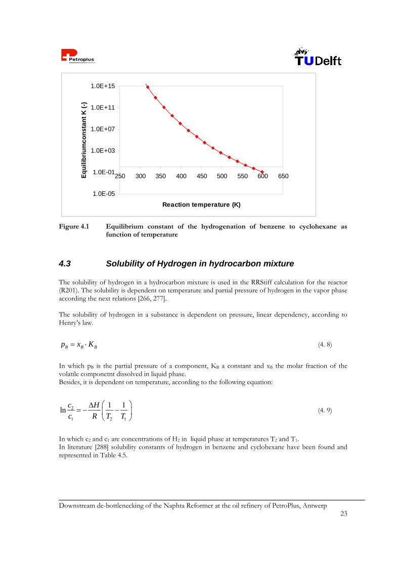
Figure 4.1 shows that the equilibrium constant is a function of temperature. At low temperature the equilibrium is more favorable than at high temperature. Therefore the reaction is carried out at relatively low temperature, below 500 K.
Downstream de-bottlenecking of the Naphta Reformer at the oil refinery of PetroPlus, Antwerp 23
1.0E-05
1.0E-01
1.0E+03
1.0E+07
1.0E+11
1.0E+15
250 300 350 400 450 500 550 600 650
Reaction temperature (K)
Eq
uil
ibri
um
con
stan
t K
(-)
Figure 4.1 Equilibrium constant of the hydrogenation of benzene to cyclohexane as
function of temperature
4.3 Solubility of Hydrogen in hydrocarbon mixture The solubility of hydrogen in a hydrocarbon mixture is used in the RRStiff calculation for the reactor (R201). The solubility is dependent on temperature and partial pressure of hydrogen in the vapor phase according the next relations [266, 277]. The solubility of hydrogen in a substance is dependent on pressure, linear dependency, according to Henry’s law.
B B Bp x K (4. 8)
In which pB is the partial pressure of a component, KB a constant and xB the molar fraction of the volatile componetnt dissolved in liquid phase. Besides, it is dependent on temperature, according to the following equation:
2
1 2 1
1 1ln
c H
c R T T
(4. 9)
In which c2 and c1 are concentrations of H2 in liquid phase at temperatures T2 and T1. In literature [288] solubility constants of hydrogen in benzene and cyclohexane have been found and represented in Table 4.5.

Downstream de-bottlenecking of the Naphta Reformer at the oil refinery of PetroPlus, Antwerp 24
Table 4.5 Solubility of hydrogen in benzene and cyclohexane
Component T [K] P [atm] P [bara] Solubility [cm3/g] Benzene 298.15 50 50.66 3.64
373.15 50 50.66 5.38Cyclohexane 298.15 45 45.60 4.88
423.15 45 45.60 8.9 For benzene and cyclohexane the solubility is available for two different temperatures, so the differential heat of solution for these components can be calculated. The operation pressure of the reactor is 25 bara. At this pressure the solubility of hydrogen in benzene and cyclohexane is given in Table 4.6. Table 4.6 Properties of solution of hydrogen in benzene and cyclohexane at 25 bara and
298.15 K
Component density solubility of H2 in organic phase H [kg/m3] [cm3 H2/g] [cm3 H2 /m3] [mole H2 /m3] [J/mole]
benzene 872.93 1.80 1.57E+06 1265.01 4818.83 cyclohexane 773.10 2.68 2.07E+06 1668.89 5042.69
For calculations to simulate the reactor a solubility of hydrogen in the organic phase of 1500 mole/m3 at a partial hydrogen pressure of 25 bara and a H of 5000 J/mole have been taken. Solubilities at other temperatures and pressures are calculated with above-mentioned formulas.
4.4 Other thermodynamic properties Thermodynamic properties like heat capacities as a function of temperature of all components, Antoine constants, validity data and saturation pressures for all relevant components are given in Appendix 12. The validity of thermodynamic data is included.
Downstream de-bottlenecking of the Naphta Reformer at the oil refinery of PetroPlus, Antwerp 25
Chapter 5 Process structure and description In former chapters the design in general is already outlined. This chapter deals with the design elements concerning process structure and detailed description. The accompanying Process Flow Scheme (PFS) and the Process Stream Summary (PSS) are respectively represented in Appendix 1 and Appendix 2.
5.1 Criteria and selections The goal of this assignment is to design a process that produces reformate which has to comply with the following restrictions: Maximum benzene content = 1 vol% Maximum Read Vapor Pressure (RVP) at 100ºF = 10 psi. Research Octane Number = 99.5
Obviously, the goal of this project is to reduce the benzene content in the reformate back to 1 vol%. But still reformate spec has to be conserved. The RVP at 100ºF (= 311K) is defined by an upper limit of 10 psi (= 68948 Pa). The quality of the reformate is indicated by the Research Octane Number (RON). The dictated RON for the reformate is 99.5 [1]. The design, all equipment including, is selected on the basis of these criteria. 5.1.1 Splitter (C201) In order to keep the RON on spec, only a part of the reformate is treated. Treating the whole reformate would lead to additional hydrogenation of other aromatics, like toluene and xylene. This results in a heavy damage of the RON, which in its turn will be off spec. A fractionator column (C201), called the Splitter, realizes the release of a benzene rich fraction, <208>, which is sent to the Hydrogenator (R201). The goal of the splitter is to release a benzene-rich effluent <208>, in which almost all of the benzene is concentrated. The Splitter releases three streams, the Top <207>, the Split <208> and the Bottom <209>. More volatile components than benzene leave the column over the Top <207>, the less volatile components through the Bottom <209>. The Split contains 90.9 wt% of the net intake of benzene, 5.5 wt% leaves C201 over the Top <207> and 3.6 wt% through the Bottom <209>. The column is operated at 1 bara. As a result the temperature of the condensate at the top <204> is 297 K. It is hard to realize this with a normal cooling medium like cooling water [20]. However, changing the pressure of the column changes the composition of the three outgoing streams. It is recommended to design a column with only a top and bottom stream, of which the top stream in total is sent to the reactor. Then the reactor dimensions need to be resized, as well as the rest of the sequencing equipment. 5.1.2 Hydrogenator (R201) To reduce the benzene content, benzene is converted into cyclohexane. This is done by catalytic hydrogenation. In theory, a catalyst is classified either as homogeneous or heterogeneous. The hydrogenation of benzene to cyclohexane is carried out with a heterogeneous catalyst. The catalyst used is HTC400 (supplied by ICI Synetix Company). Basically, it is nickel metal on an alumina carrier. The shape of the catalyst is a trilobe, with a diameter of 1 mm and a length of 3 mm. More specifications on the catalyst properties and the catalyst selection are given in Appendix 13. Before startup, the catalyst must be prereduced in a hydrogen-rich atmosphere at 1 bara and 250 ºC. This temperature is reached with use of an electrical heater. Prereduction is necessary, since the catalyst is purchased in passivated

Downstream de-bottlenecking of the Naphta Reformer at the oil refinery of PetroPlus, Antwerp 26
state. The several states of the catalyst are also given in Appendix 13. A brief calculation of the heat duty required by the electrical heater for the prereduction is given in Appendix 14. Advantage of heterogeneous catalysis is the ease of separation of catalyst from the product and in industry a common catalyst for hydrogenation is availabe. A monolithic reactor is not selected because of difficulties in catalyst regeneration. Furthermore, it is not a very known and therefore a risky application in industrial processes for benzene hydrogenation. The reaction is carried out in a trickle bed reactor, in which liquid trickles over a fixed bed of catalyst, while hydrogen gas flows co-currently downwards as a continuous phase. In most commercial trickle bed operations, the liquid phase is believed to move in plug flow. Disadvantages of a trickle bed reactor are the relative high pressure drop and the possibility of maldistribution, which can cause hot spots. In combination with the exothermic reaction of benzene into cyclohexane, this leads to the important fact that cooling of the reactor requires special attention. The feed of the reactor <111> (at 343 K) is split up in <212> and <213>. Also the reactor bed is divided into two parts. Stream <212> is the feed for the first bed. Due to the exothermic reaction the temperature rises. Halfway, before the second bed, stream <213> is introduced into the reactor as a quench. Besides, the reactor is cooled by a cooling jacket. The effluent of the reactor <214> is cooled by E204 to 298 K. For kinetic reasons the operation condition of the reactor are at 25 bara and the initial temperature is 343 K. The maximum allowed temperature is 425 K, since when this temperature is exceeded, the critical temperature for some of the components in the reactor is reached. An operating pressure of 25 bara is selected because of three reasons. First, the kinetics have been derived from previous experiments, carried out at this pressure. Second, hydrogen must be present in excess in order to ensure unlimited availability of this reactant. This must be kept an eye on, since hydrogen must be first dissolved into the liquid phase. Third, a hydrogen excess would prevent the catalyst from fast deactivation. 5.1.3 HP and LP Separator (V202 & V203) The hydrogen has to be separated from the Reactor effluent <214>. The hydrogen, which is left after reaction, is valuable for the Naphta Hydro Treater (NHT) and Desulphurizing units. The major part is discharged by the gas-liquid HP Separator (V202). The HP separator is operated at 23 bara. The pressure drop from the reactor R201 to V202 is caused by the heat exchanger E204. The operation temperature of the HP separator is 298 K. At higher temperature, the HP releases too much product by the vapor discharge. This vapor is easily discharged to the NHT, which operates at 20 bara. The liquid is discharged to the LP separator (V203). The LP separator is needed to remove the rest of gaseous components and operates at 1 bara to ensure the RVP to be on spec. The pressure of the outgoing vapor has to be enhanced up to 4 bara to enable a discharge as Fuel Gas. The compressor K201 fulfills this function in order to direct the LP vapor easily to the FG network. 5.1.4 Blending to final reformate The intake of the Debenzenizer unit is reformate from the reformer section, referred as original reformate. The original reformate has an RVP of 9.21 psi. Before entering the Debenzenizer section, the C3 and C4 components will be removed, as agreed with the principal. This leads to a decrease of the RVP of the reformate intake <201>. The only factors that influence the RVP of the final reformate, <231>, are hydrogen that remains in the product stream after HP and LP separator, and the conversion of benzene into cyclohexane. Other components that are present in the mixture will not be affected. After passing the HP and LP separators nearly all H2 is removed out of the product stream. Therefore the contribution of H2 to the RVP is neglected. The conversion of benzene into cyclohexane does not the affect the RVP as well, since benzene is slightly less volatile than cyclohexane (RVP 3.224 and 3.266 psi respectively). The assumption is made that the blend of the Top <207>, LP liquid discharge <220> and Cooled Bottom <225> stream does not exceed the RVP restriction (see Appendix 15, in which the RON and the RVP of the final reformate are calculated and discussed). The
Downstream de-bottlenecking of the Naphta Reformer at the oil refinery of PetroPlus, Antwerp 27
Bottom <209> stream is cooled by E203 and E205, to 40 ºC for storage and to meet legislation of the maximum outside temperature of pipelines. The RON certainly is affected by the hydrogenation of benzene. Benzene has a much higher RON than cyclohexane (106 and 80 respectively). Therefore only 91% of the Top <207> in blended to the Blend <226>, to obtain a reformate product with RON 99.5. For detailed calculations of RVP and RON in detail the reader is referred to Appendix 15.
5.2 Process Flow Scheme The PFS is presented in Appendix 1 In the PFS the line-up of the various unit operations and their connection with process flows are represented in a clear overview. In this section, the PFS is explained in detail. Temperatures and pressures of all streams can be found in the PFS itself. Flow rates are given in the PSS, which can be found in Appendix 2. Control of the process is also given in the PFS, a detailed description is given in chapter 6. More information about the equipment properties is discussed in chapter 8. The reformate stream <201> which from the reformer stabilizers of the Naphta reformer section. Stream <115> is slightly different than stream <201>. The C3 en C4 components have been taken out of the reformate intake <201>. This is done to avoid problem is the top of the Splitter column and the Condensor. Stream <201> flows into the splitter (C201). There the components of the reformate are separated on the basis of difference in volatility. The top stream <207> exists of C5 components and is partially blended with the product stream. The side stream <208> has large contents of benzene. This stream has to be hydrogenated in the Hydrogenator (R201). The bottom stream of the splitter <209> exists of C6+ components. To hydrogenate the benzene that enters the Hydrogenator (R201), there is also supplied a hydrogen-rich stream <202>. The reactor effluent, <214> is a liquid-vapor mixture. Vapor and liquids are separated from each other in two separators (V202) and (V203). The liquid outflow of these separators is partially recycled and mixed with the Split stream <208> to dilute the benzene concentrate of streams <212> and <213>. The remaining part of the liquid effluent of the separators <223> is blended with the bottom stream <225> together with a part of the Top stream to obtain the final product. The vapor outflow of the HP separator (V202), <216> is used for the naphta hydrotreater. The vapor outflow of the LP separator (V203), <230> is used as fuel gas.
5.3 Utilities In this section the utilities required for the Debenzenizer units are described. The major energy users are the heat exchangers. A utility summary is given in Appendix 9. 5.3.1 Heat exchangers The selection of heat exchanger types will be described briefly. For more details, the reader is referred to the equipment specification sheets, Appendix 17. The reactor (R201) is cooled with water by a cooling jacket, since this relatively simple and cheap approach fulfils the required cooling duty. The heat exchanger for the condenser (E201) has been designed to be a finned tube type, because a large cooling area is required and because of the small temperature difference between the cooling water and the top temperature. The other heat exchangers (E202 through E205) consist of fixed tube sheets. The reboiler of the column (E202) is heated with saturated steam at 7.9 bara, supplied by the existing utility network. Cooling with air is the cheapest option, but with water lower temperatures can be reached. The condenser of the column (E201) is cooled with cooling water, because cooling with air is not possible. The effluent of the reactor <214> (E204) is partially cooled with air and partially cooled with water.

Downstream de-bottlenecking of the Naphta Reformer at the oil refinery of PetroPlus, Antwerp 28
In E203 there is heat integration between recycle stream <221> and bottom stream <209>. The bottom stream is farther cooled with cooling water in E205. Eventually this stream can be cooled with air, but due to a lower overall heat transfer coefficient and temperature difference the required heat exchanging area would be larger and therefore is not selected. 5.3.2 Pumps In the chemical process industry, the single stage, horizontal centrifugal pump is by far the most commonly used. Pump selection is made on the flow rate and liquid head required, together with other process considerations, such as corrosion or the presence of solids in the fluid. All pumps in this design are single stage centrifugal pumps. This selection is based on the calculated combination of flow rates and total liquid heads. The feed pump for the Hydrogenator may be a multi stage centrifugal pump, but a high speed single stage is also suitable. The latter one has been selected. (see Appendix 18) [20]. One pump is used for both the reflux stream of the splitter and the transfer of the top stream to blending and storage. Although centrifugal pumps do not provide the highest efficiency amongst pumps, given the Debenzenizer process conditions, the single stage centrifugal pump is the logical and best applicable alternative. All designed pumps have efficiencies between 60 and 70% and there is a spare device for each pump in case of pump failure. 5.3.3 Compressor The selection of the type of compressor depends on the flow rate, the pressure difference required and the operating pressure. The (inlet) gas flow rate is 0.171 m3/s and discharge pressure is calculated to be 4.2 bara, including the pressure drop in the pipelines. This combination results in selecting a centrifugal compressor [20].
5.4 Materials selection For all designed equipment, the materials of construction have been selected. This was done on the basis of the components present in the units. Also the operating conditions and financial aspects were taken into account. For a summary of the reasoning during the material selection, the reader is referred to Appendix 19.
5.5 Process Yields In Appendix 20 the amount of all inlet and outlet process streams and utilities of the Debenzenizer units are given. On the base of these values, the process yields are calculated. The process yields represent the amount of all required flows of process streams and utilities divided by the amount of product in a certain time interval. All flows and yields are also represented in a block scheme. The flows are given in ton/h and the yields in ton/ton product.
Downstream de-bottlenecking of the Naphta Reformer at the oil refinery of PetroPlus, Antwerp 29
Chapter 6 Process control During the design of the Debenzenizer attention has been paid to the controllability of the process. The most important parts of the process to be controlled are the Splitter (C201), the Hydrogenator (R201) and the feed and effluent streams. Other main points regarding control are the required pressure drop between the HP separator (V202) and the LP separator (V203) and the ratio between the flows of two flows of the reactor. The applied process controllers are also introduced in the PFS. For all control elements a range is used instead of a setpoint. This is chosen because fluctuations cannot be avoided. Responding to every fluctuation occurring would be useless. Control considerations and design features are based on principles, given in [29].
6.1 Control of the Splitter (C201) Several control elements and loops are needed to control the splitter. An overview of the type of control used is represented in Table 6.1. The temperatures of both the top and bottom of C201 have to be controlled. In both parts of C201 this is done with a cascade control. In case of the top, the master control loop is the loop that measures T and the slave loop is the loop that measures the reflux flow. Regarding the bottom, the master control loop is again the loop that measures T. The slave control loop is the loop that measures the ingoing flow of the steam in the kettle reboiler E202, a valve is implemented in this flow to perform the required control action. The composition of the Split stream <208> is also controlled with a cascade control. The temperature is measured in the column. The loop in which this temperature is measured is the master control loop. The loop in which the flow of stream <208> is measured is the slave control loop. Furthermore the pressure in the top is controlled, again by using cascade control. The pressure is measured in stream <203>. The loop in which the pressure is measured is the master control loop. In the slave control loop the flow of the cooling water stream in E201 is measured. In this same water stream a valve is implemented. When the pressure rises above the demanded pressure, the valve is opened. When the valve is already entirely open and the pressure is still above the demanded pressure, the valve of stream <228> is opened. In stream <228> there is normally no flow. Two level controllers are applied. One is used to control the liquid level in the reflux total condenser (V201) at the top of C201. The other one controls the level in the bottom of C201. Adding a flow control to the feed stream <201> controls the feed of C201.
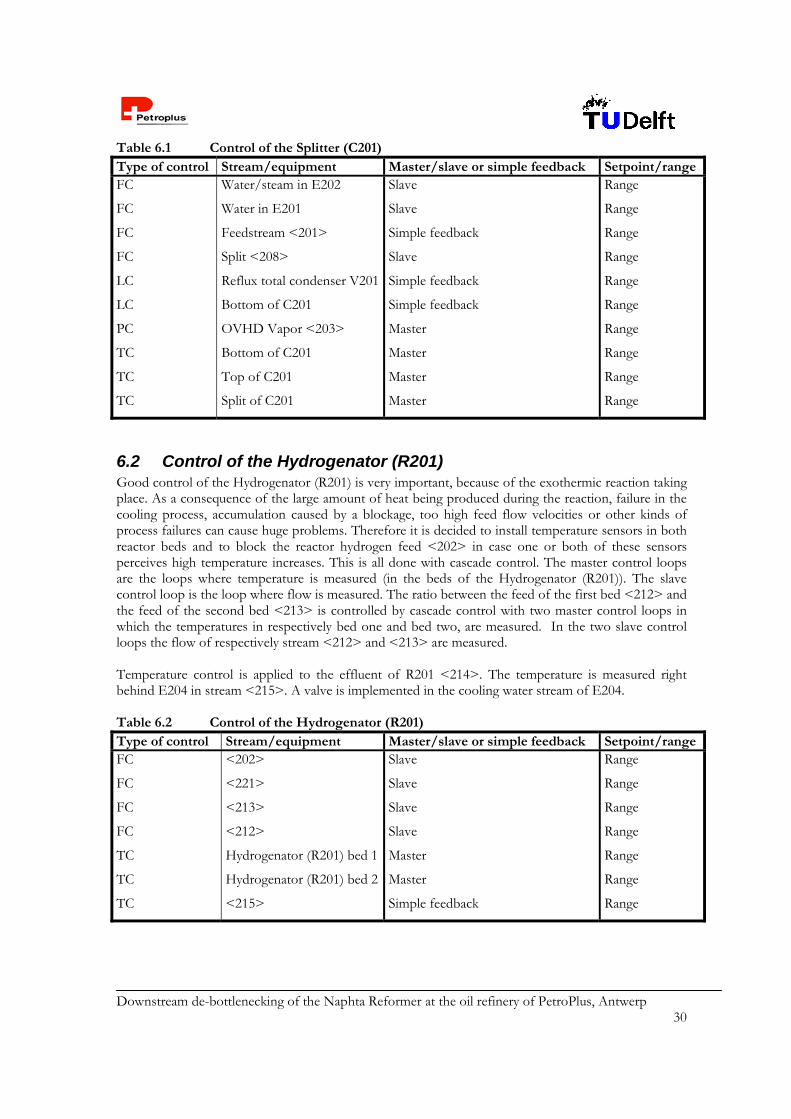
Downstream de-bottlenecking of the Naphta Reformer at the oil refinery of PetroPlus, Antwerp 30
Table 6.1 Control of the Splitter (C201) Type of control Stream/equipment Master/slave or simple feedback Setpoint/rangeFC
FC
FC
FC
LC
LC
PC
TC
TC
TC
Water/steam in E202
Water in E201
Feedstream <201>
Split <208>
Reflux total condenser V201
Bottom of C201
OVHD Vapor <203>
Bottom of C201
Top of C201
Split of C201
Slave
Slave
Simple feedback
Slave
Simple feedback
Simple feedback
Master
Master
Master
Master
Range
Range
Range
Range
Range
Range
Range
Range
Range
Range
6.2 Control of the Hydrogenator (R201) Good control of the Hydrogenator (R201) is very important, because of the exothermic reaction taking place. As a consequence of the large amount of heat being produced during the reaction, failure in the cooling process, accumulation caused by a blockage, too high feed flow velocities or other kinds of process failures can cause huge problems. Therefore it is decided to install temperature sensors in both reactor beds and to block the reactor hydrogen feed <202> in case one or both of these sensors perceives high temperature increases. This is all done with cascade control. The master control loops are the loops where temperature is measured (in the beds of the Hydrogenator (R201)). The slave control loop is the loop where flow is measured. The ratio between the feed of the first bed <212> and the feed of the second bed <213> is controlled by cascade control with two master control loops in which the temperatures in respectively bed one and bed two, are measured. In the two slave control loops the flow of respectively stream <212> and <213> are measured. Temperature control is applied to the effluent of R201 <214>. The temperature is measured right behind E204 in stream <215>. A valve is implemented in the cooling water stream of E204. Table 6.2 Control of the Hydrogenator (R201) Type of control Stream/equipment Master/slave or simple feedback Setpoint/rangeFC
FC
FC
FC
TC
TC
TC
<202>
<221>
<213>
<212>
Hydrogenator (R201) bed 1
Hydrogenator (R201) bed 2
<215>
Slave
Slave
Slave
Slave
Master
Master
Simple feedback
Range
Range
Range
Range
Range
Range
Range
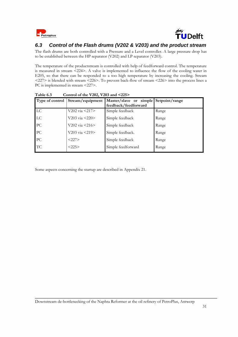
Downstream de-bottlenecking of the Naphta Reformer at the oil refinery of PetroPlus, Antwerp 31
6.3 Control of the Flash drums (V202 & V203) and the product stream The flash drums are both controlled with a Pressure and a Level controller. A large pressure drop has to be established between the HP separator (V202) and LP separator (V203). The temperature of the productstream is controlled with help of feedforward control. The temperature is measured in stream <224>. A valve is implemented to influence the flow of the cooling water in E205, so that there can be responded to a too high temperature by increasing the cooling. Stream <227> is blended with stream <226>. To prevent back-flow of stream <226> into the process lines a PC is implemented in stream <227>. Table 6.3 Control of the V202, V203 and <225> Type of control Stream/equipment Master/slave or simple
feedback/feedforward Setpoint/range
LC
LC
PC
PC
PC
TC
V202 via <217>
V203 via <220>
V202 via <216>
V203 via <219>
<227>
<225>
Simple feedback
Simple feedback
Simple feedback
Simple feedback.
Simple feedback
Simple feedforward
Range
Range
Range
Range
Range
Range
Some aspects concerning the startup are described in Appendix 21.
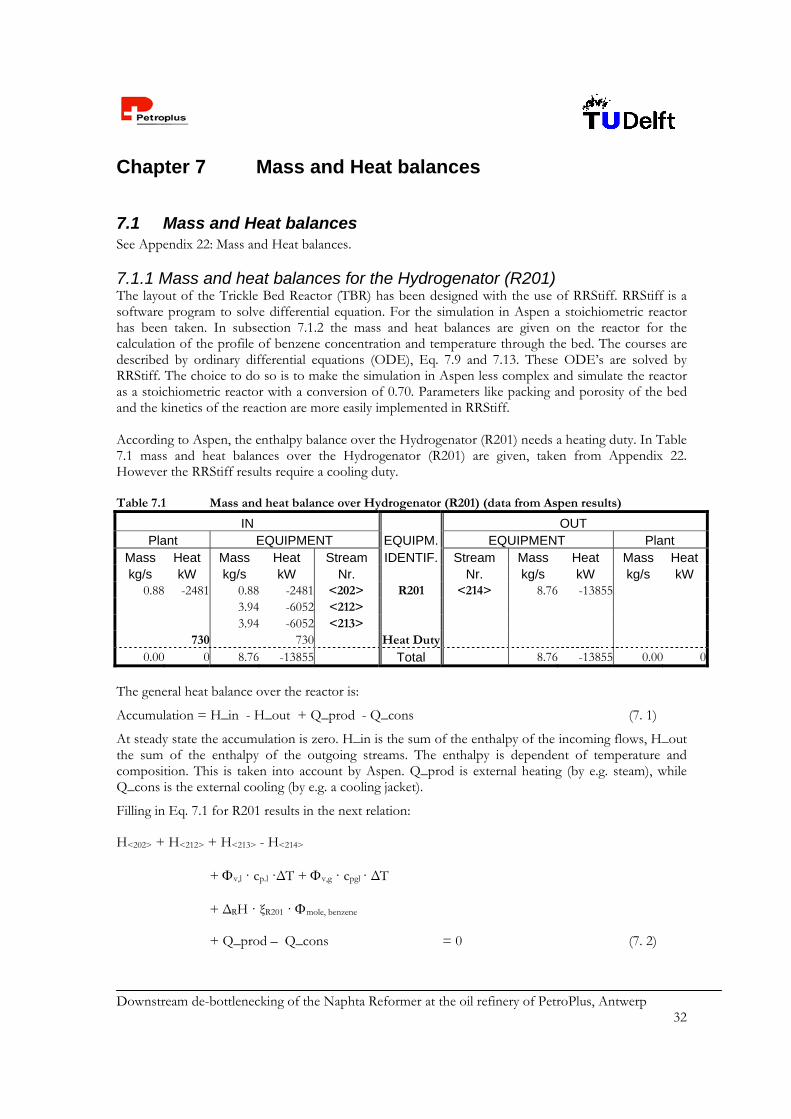
Downstream de-bottlenecking of the Naphta Reformer at the oil refinery of PetroPlus, Antwerp 32
Chapter 7 Mass and Heat balances
7.1 Mass and Heat balances See Appendix 22: Mass and Heat balances. 7.1.1 Mass and heat balances for the Hydrogenator (R201) The layout of the Trickle Bed Reactor (TBR) has been designed with the use of RRStiff. RRStiff is a software program to solve differential equation. For the simulation in Aspen a stoichiometric reactor has been taken. In subsection 7.1.2 the mass and heat balances are given on the reactor for the calculation of the profile of benzene concentration and temperature through the bed. The courses are described by ordinary differential equations (ODE), Eq. 7.9 and 7.13. These ODE’s are solved by RRStiff. The choice to do so is to make the simulation in Aspen less complex and simulate the reactor as a stoichiometric reactor with a conversion of 0.70. Parameters like packing and porosity of the bed and the kinetics of the reaction are more easily implemented in RRStiff. According to Aspen, the enthalpy balance over the Hydrogenator (R201) needs a heating duty. In Table 7.1 mass and heat balances over the Hydrogenator (R201) are given, taken from Appendix 22. However the RRStiff results require a cooling duty. Table 7.1 Mass and heat balance over Hydrogenator (R201) (data from Aspen results)
IN OUT Plant EQUIPMENT EQUIPM. EQUIPMENT Plant
Mass Heat Mass Heat Stream IDENTIF. Stream Mass Heat Mass Heat kg/s kW kg/s kW Nr. Nr. kg/s kW kg/s kW
0.88 -2481 0.88 -2481 <202> R201 <214> 8.76 -13855 3.94 -6052 <212> 3.94 -6052 <213> 730 730 Heat Duty
0.00 0 8.76 -13855 Total 8.76 -13855 0.00 0
The general heat balance over the reactor is:
Accumulation = H_in - H_out + Q_prod - Q_cons (7. 1)
At steady state the accumulation is zero. H_in is the sum of the enthalpy of the incoming flows, H_out the sum of the enthalpy of the outgoing streams. The enthalpy is dependent of temperature and composition. This is taken into account by Aspen. Q_prod is external heating (by e.g. steam), while Q_cons is the external cooling (by e.g. a cooling jacket).
Filling in Eq. 7.1 for R201 results in the next relation:
H<202> + H<212> + H<213> - H<214>
+ v,l · cp.l ·ΔT + v,g · cpgl · ΔT
+ ΔRH · ξR201 · mole, benzene
+ Q_prod – Q_cons = 0 (7. 2)
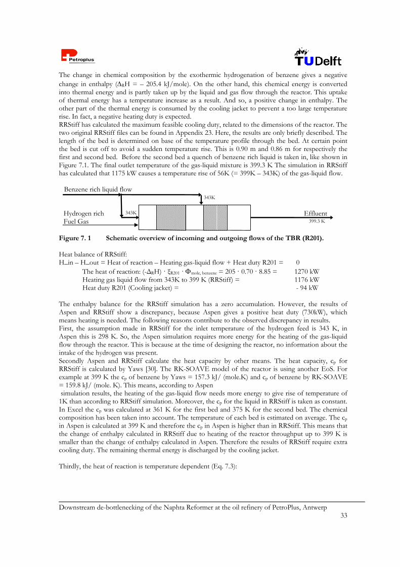
Downstream de-bottlenecking of the Naphta Reformer at the oil refinery of PetroPlus, Antwerp 33
The change in chemical composition by the exothermic hydrogenation of benzene gives a negative change in enthalpy (RH = – 205.4 kJ/mole). On the other hand, this chemical energy is converted into thermal energy and is partly taken up by the liquid and gas flow through the reactor. This uptake of thermal energy has a temperature increase as a result. And so, a positive change in enthalpy. The other part of the thermal energy is consumed by the cooling jacket to prevent a too large temperature rise. In fact, a negative heating duty is expected. RRStiff has calculated the maximum feasible cooling duty, related to the dimensions of the reactor. The two original RRStiff files can be found in Appendix 23. Here, the results are only briefly described. The length of the bed is determined on base of the temperature profile through the bed. At certain point the bed is cut off to avoid a sudden temperature rise. This is 0.90 m and 0.86 m for respectively the first and second bed. Before the second bed a quench of benzene rich liquid is taken in, like shown in Figure 7.1. The final outlet temperature of the gas-liquid mixture is 399.3 K The simulation in RRStiff has calculated that 1175 kW causes a temperature rise of 56K (= 399K – 343K) of the gas-liquid flow. Figure 7. 1 Schematic overview of incoming and outgoing flows of the TBR (R201). Heat balance of RRStiff: H_in – H_out = Heat of reaction – Heating gas-liquid flow + Heat duty R201 = 0
The heat of reaction: (-ΔRH) · ξR201 · mole, benzene = 205 · 0.70 · 8.85 = 1270 kW Heating gas liquid flow from 343K to 399 K (RRStiff) = 1176 kW Heat duty R201 (Cooling jacket) = - 94 kW
The enthalpy balance for the RRStiff simulation has a zero accumulation. However, the results of Aspen and RRStiff show a discrepancy, because Aspen gives a positive heat duty (730kW), which means heating is needed. The following reasons contribute to the observed discrepancy in results. First, the assumption made in RRStiff for the inlet temperature of the hydrogen feed is 343 K, in Aspen this is 298 K. So, the Aspen simulation requires more energy for the heating of the gas-liquid flow through the reactor. This is because at the time of designing the reactor, no information about the intake of the hydrogen was present. Secondly Aspen and RRStiff calculate the heat capacity by other means. The heat capacity, cp for RRStiff is calculated by Yaws [30]. The RK-SOAVE model of the reactor is using another EoS. For example at 399 K the cp of benzene by Yaws = 157.3 kJ/ (mole.K) and cp of benzene by RK-SOAVE = 159.8 kJ/ (mole. K). This means, according to Aspen simulation results, the heating of the gas-liquid flow needs more energy to give rise of temperature of 1K than according to RRStiff simulation. Moreover, the cp for the liquid in RRStiff is taken as constant. In Excel the cp was calculated at 361 K for the first bed and 375 K for the second bed. The chemical composition has been taken into account. The temperature of each bed is estimated on average. The cp in Aspen is calculated at 399 K and therefore the cp in Aspen is higher than in RRStiff. This means that the change of enthalpy calculated in RRStiff due to heating of the reactor throughput up to 399 K is smaller than the change of enthalpy calculated in Aspen. Therefore the results of RRStiff require extra cooling duty. The remaining thermal energy is discharged by the cooling jacket. Thirdly, the heat of reaction is temperature dependent (Eq. 7.3):
Hydrogen rich Fuel Gas
Benzene rich liquid flow
Effluent 343K
399.3 K
343K
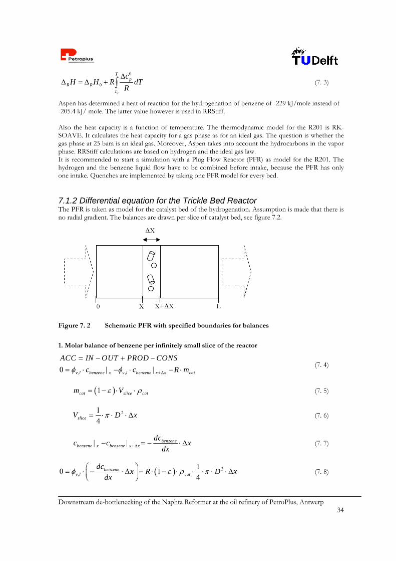
Downstream de-bottlenecking of the Naphta Reformer at the oil refinery of PetroPlus, Antwerp 34
0
0
0
Tp
R R
T
cH H R dT
R
(7. 3)
Aspen has determined a heat of reaction for the hydrogenation of benzene of -229 kJ/mole instead of -205.4 kJ/ mole. The latter value however is used in RRStiff. Also the heat capacity is a function of temperature. The thermodynamic model for the R201 is RK-SOAVE. It calculates the heat capacity for a gas phase as for an ideal gas. The question is whether the gas phase at 25 bara is an ideal gas. Moreover, Aspen takes into account the hydrocarbons in the vapor phase. RRStiff calculations are based on hydrogen and the ideal gas law. It is recommended to start a simulation with a Plug Flow Reactor (PFR) as model for the R201. The hydrogen and the benzene liquid flow have to be combined before intake, because the PFR has only one intake. Quenches are implemented by taking one PFR model for every bed. 7.1.2 Differential equation for the Trickle Bed Reactor The PFR is taken as model for the catalyst bed of the hydrogenation. Assumption is made that there is no radial gradient. The balances are drawn per slice of catalyst bed, see figure 7.2.
Figure 7. 2 Schematic PFR with specified boundaries for balances
1. Molar balance of benzene per infinitely small slice of the reactor
, ,0 v l benzene x v l benzene x x cat
ACC IN OUT PROD CONS
c c R m
| |
(7. 4)
1cat slice catm V (7. 5)
21
4sliceV D x (7. 6)
benzenebenzene x benzene x x
dcc c x
dx | | (7. 7)
2,
10 1
4benzene
v l cat
dcx R D x
dx
(7. 8)
0 X X+X L
X
Downstream de-bottlenecking of the Naphta Reformer at the oil refinery of PetroPlus, Antwerp 35
2
,
11
4catbenzene
v l
R Ddc
dx
(7. 9)
2. Energy balance per infinitely small slice of the reactor
, ,
, ,
0
v l p l
v gas p gas cat R slice outside
ACC IN OUT PROD CONS
c T T
c T T R m H U A T T
x x+ x
x x+ x x
| |
| | |
(7. 10)
dTT T x
dx x x+ x| | (7. 11)
, , , ,
2
0
1 1
4
v l p l v gas p gas
cat R outside
dTc c x
dx
R D x H U D x T T
(7. 12)
2
, , , ,
11
4cat R outside
v l p l v gas p gas
R D H U D T TdT
dx c c
(7. 13)
1
11/3 1
A H A H
A A H H
k K K c cR
K c K c
(7. 14)
01 1,0
1 1exp A
T
Ek k
R T T
(7. 15)
7.2 Heat Integration In this design, besides the heat requirements of the column, there are the next cooling and heating requirements; Cooling of reactor effluent <214> from 399 K to 293 K. Total required heat duty is 2847 kW. Heating of recycle stream <221> from 291 K to 343 K. The required heat duty is 654 kW. Cooling of bottom stream of splitter <209> from 392 K to 313 K. Total required heat duty is
1708 kW. There has been chosen for heat integration between the Bottom stream of the Splitter <209> and the Recycle stream <221>. The amount of heat transferred between these flows is 654 kW. This is done by heat exchanger E203. Calculations for the heat exchanger properties are represented in Appendix 24. Also the results are given in the specification sheets, Appendix 17.

Downstream de-bottlenecking of the Naphta Reformer at the oil refinery of PetroPlus, Antwerp 36
Chapter 8 Process and Equipment Design
8.1 Integration by Process Simulation The Debenzenizer process, except for the Trickle Bed Reactor (TBR) (R201) is simulated with the use of Aspen. The dimensions and layout of the TBR is designed with the use of RRStiff. The magnitude of the recycle stream is first calculated in Matlab (See Appendix 8).
8.2 Equipment Selection and Design 8.2.1 Splitter The splitter is simulated in Aspen using Petrofrac as a rigorous fractionation model. The column exists of 54 stages. Less stages had a too high benzene content in the Top stream as a result. More stages do not contribute to a more satisfying separation and only yield more additional costs. The average plate spacing is 0.5 m. The kettle reboiler takes more space (~2 m). The total height of the column is taken as 30 m. Calculations on the column diameter and the tray physical properties are given in Appendix 25. More details about the column are given in the equipment summary and specification sheets, Appendices 16 and 17 respectively. 8.2.2 Hydrogenator The Reactor in Aspen is modeled as a stoichiometric reactor. To meet the restriction of 1 vol% of benzene a conversion of 70% is already sufficient. The dimensions and layout of the reactor are determined on base of the temperature and concentration profile through the reactor. The accompanying mass and heat balances are given in Chapter 7. The calculation of these diffential equations is done in RRStiff. The conversion is taken as fixed, where the length of the bed is variable. The length of the bed is determined for reasons as given in Chapter 5. Then a second bed is starting. Calculation of the temperature and concentration profile stops, when conversion of 0.70 is reached. The reactor has a diameter of 0.8 m and has two separated beds. The length of the first bed is 0.90 m and the second bed 0.86 m. In Appendix 26 a schematic view of the reactor layout is given. The RRStiff input files are represented in Appendix 23. The reactor is divided in two sections. Each section includes a distribution device and a catalyst bed. The distribution device for the first section is a combination of sprayers and a 30 cm high inert bed of ceramic balls (with a diameter of 0.6 cm), which is implemented above the catalyst bed. The sprayers and the inert bed provide a good distribution of gas and liquid over the first catalyst bed. The effluent of the first catalyst bed and the stream injected between first and second catalyst bed, <213>, are mixed on a plate with little holes in it. After passing this plate a second inert bed of ceramic balls above the second catalyst bed provides a good distribution of gas and liquid over the catalyst bed. The dimensions of the second inert bed are the same as the first one. Moreover both catalyst beds with a diameter of 0.8 m have a length of about 0.9 m, so they are relatively short. Therefore the chance of deviation from plug flow and a hot spot is small. The length of first section of the reactor is taken as 2 m and for the second section 1.5 m. Together the length of the reactor is 3.5 m. The pressure in reactor is assumed to be constant, because there is only a little pressure drop about the catalyst beds. The pressure drop is calculated with the Cozeny-Carman equation, Eq. 8.1. [31];

Downstream de-bottlenecking of the Naphta Reformer at the oil refinery of PetroPlus, Antwerp 37
22
3
5 1~ 5000 /vu S
p Pa m
(8. 1)
Moreover the pressure in the reactor hardly influences the results of the calculations in RRStiff. So in the calculations for the dimensions of the reactor, the pressure has been taken constant. Both catalyst beds are cooled with a cooling water jacket, the overall heat transfer coefficient is assumed to be 300 W/(m2.K). The height of the whole reactor is assumed to be ca. 3.5 m. For the diameter there has been taken a value of 0.8 m. The porosity of the catalyst beds is 0.33846 and the pressure of the reactor is 25 bara. The total volume of both catalyst beds is 0.88 m3. The amount of catalyst in the reactor is 0.88*(1-0.33846)=0.585 m3 = 760.82 kg. The reactor is made from carbon steel, HII; this is advised by the principal. 8.2.3 Flash Drums Calculations have been performed to estimate the dimensions of the hydrogen separators. A method as described in [322] has been used, which makes use of the separation factor and its relationship to the system constant. The dimensions of the HP Separator (V202) as well as for the LP Separator (V203) have been determined with this method and their volumes are both 0.612 m3. The liquid and vapor height of these vertical flash drums can be varied to some extent, but the ratio of (Hliq+Hvap)/diam must be kept between 3 and 5. Otherwise, a horizontal drum should be considered. A calculation example is enclosed in Appendix 27. 8.2.4 Heat exchangers Six heat exchangers have been designed.: Condensor (E201) Kettle reboiler (E202) Heat exchanger for heating <221>, (E203) Heat exchanger for cooling <209>, (E203) Cooling reactor effluent (E204) Cooling product stream (E205) For calculations of the required utilities the equations below have been used [20].
meanQ U A T (8. 2)
mean lm tT T F (8. 3)
1 2 2 1
1 2
2 1
lnlm
T t T tT
T tT t
(8. 4)
Downstream de-bottlenecking of the Naphta Reformer at the oil refinery of PetroPlus, Antwerp 38
0m pQ c T T (8. 5)
In which Q is the heat duty [W], U the overall heat transfer coefficient [W/(m2.K)], Tmean the corrected logarithmic temperature difference [K], Tlm the logarithmic mean temperature difference [K], Ft the correction factor [-], T1 and T2 respectively the inlet and outlet shell side fluid temperature [K], t1 and t2 respectively the inlet and outlet tube side fluid temperature [K], m the mass flow of the cooling/heating medium, cp the heat capacity of the medium [J/(kg.K)], T the outlet temperature [K] and T0 the inlet temperature [K]. For calculations of the heat exchanger properties the reader is referred to Appendix 24. 8.2.5 Pumps In appendix 18, a calculation example (for P201) of the required pump power is given. The procedure is given in this subsection [20]. The theoretical power needed for pumping an incompressible fluid is given by:
theoretical vPower p (8. 6)
In which v is the volumetric flow rate [m3/s] and p is the pressure drop [Pa]. Then the power is given in [W]. The pressure drop is the sum of two terms: The pressure difference between the pump input and output stream. The pressure drop over the pipelines and other intermediate units, like the heat exchanger for the
Splitter bottom stream. The pressure drop over the pipelines is given by the following equation:
2
8 ( / )2f i
uP f L d
(8. 7)
In which Pf is the total pipeline pressure drop [N/m2], f the friction factor [-], L the pipe length [m], di the internal pipe diameter [m], the fluid density [kg/m3] and u the fluid velocity [m/s]. Dividing the calculated theoretical power by the centrifugal pump efficiency gives the actual power:
100theoractual
PPower
(8. 8)
In which is the pump efficiency in percentages. The pump efficiency is dependent on the type of pump used and the operating conditions, like the liquid capacity and the liquid head. Efficiencies for centrifugal pumps are retrieved from [20]. The results for pumps P201 through P203 are given in the specification sheets presented in Appendix 17. 8.2.6 Compression A compressor is needed to transport the hydrogen-rich gas stream <230> from the LP Separator. This gas has to be compressed from 1 bara to 4 bara for transportation to the fuel gas storage tank.
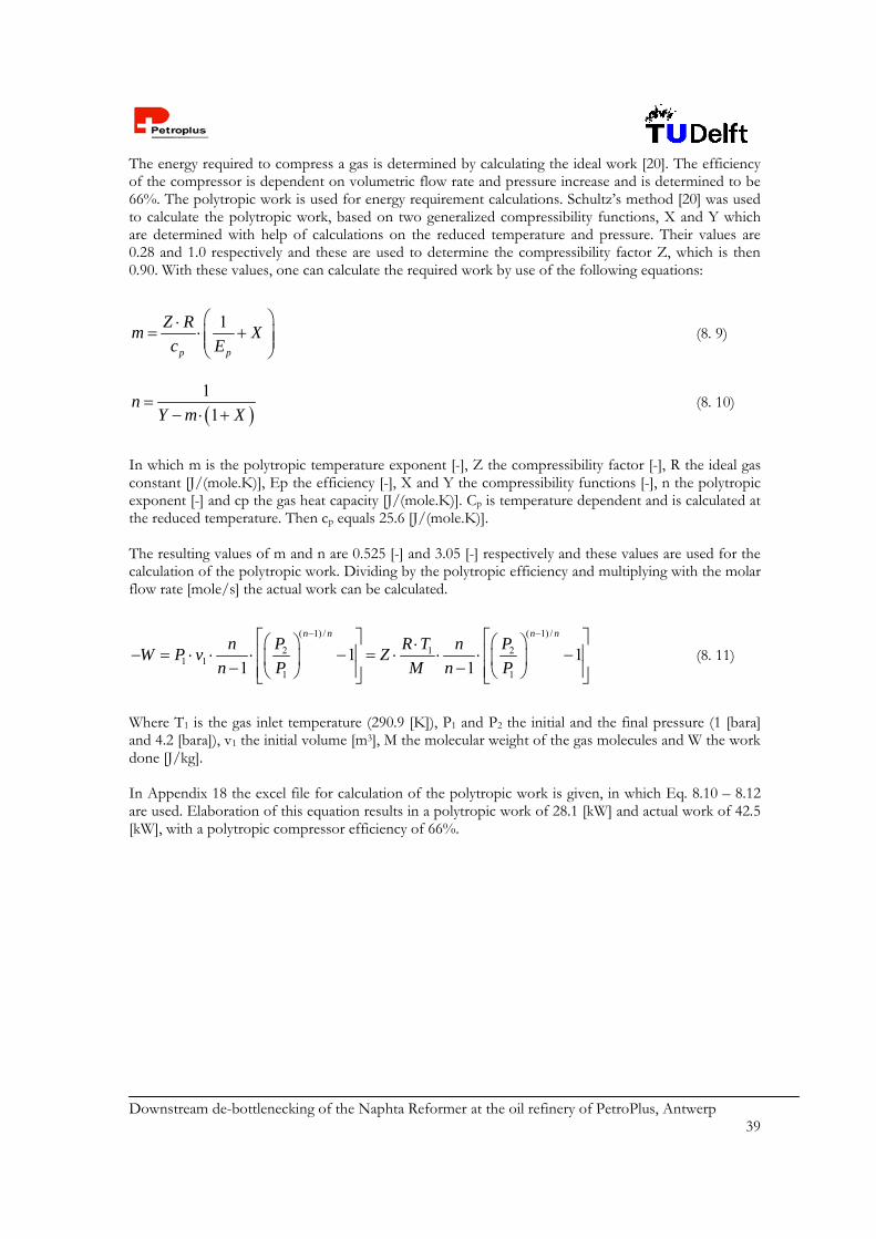
Downstream de-bottlenecking of the Naphta Reformer at the oil refinery of PetroPlus, Antwerp 39
The energy required to compress a gas is determined by calculating the ideal work [20]. The efficiency of the compressor is dependent on volumetric flow rate and pressure increase and is determined to be 66%. The polytropic work is used for energy requirement calculations. Schultz’s method [20] was used to calculate the polytropic work, based on two generalized compressibility functions, X and Y which are determined with help of calculations on the reduced temperature and pressure. Their values are 0.28 and 1.0 respectively and these are used to determine the compressibility factor Z, which is then 0.90. With these values, one can calculate the required work by use of the following equations:
1
p p
Z Rm X
c E
(8. 9)
1
1n
Y m X
(8. 10)
In which m is the polytropic temperature exponent [-], Z the compressibility factor [-], R the ideal gas constant [J/(mole.K)], Ep the efficiency [-], X and Y the compressibility functions [-], n the polytropic exponent [-] and cp the gas heat capacity [J/(mole.K)]. Cp is temperature dependent and is calculated at the reduced temperature. Then cp equals 25.6 [J/(mole.K)]. The resulting values of m and n are 0.525 [-] and 3.05 [-] respectively and these values are used for the calculation of the polytropic work. Dividing by the polytropic efficiency and multiplying with the molar flow rate [mole/s] the actual work can be calculated.
( 1) / ( 1) /
2 1 21 1
1 1
1 11 1
n n n nn P R T n P
W P v Zn P M n P
(8. 11)
Where T1 is the gas inlet temperature (290.9 [K]), P1 and P2 the initial and the final pressure (1 [bara] and 4.2 [bara]), v1 the initial volume [m3], M the molecular weight of the gas molecules and W the work done [J/kg]. In Appendix 18 the excel file for calculation of the polytropic work is given, in which Eq. 8.10 – 8.12 are used. Elaboration of this equation results in a polytropic work of 28.1 [kW] and actual work of 42.5 [kW], with a polytropic compressor efficiency of 66%.
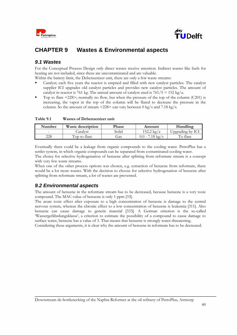
Downstream de-bottlenecking of the Naphta Reformer at the oil refinery of PetroPlus, Antwerp 40
CHAPTER 9 Wastes & Environmental aspects
9.1 Wastes For the Conceptual Process Design only direct wastes receive attention. Indirect wastes like fuels for heating are not included, since these are uncontaminated and are valuable. Within the battery limit, the Debenzenizer unit, there are only a few waste streams: Catalyst; each five years the reactor is emptied and filled with new catalyst particles. The catalyst
supplier ICI upgrades old catalyst particles and provides new catalyst particles. The amount of catalyst in reactor is 761 kg. The annual amount of catalyst used is 761/5 = 152 kg/a.
Top to flare <228>; normally no flow, but when the pressure of the top of the column (C201) is increasing, the vapor in the top of the column will be flared to decrease the pressure in the column. So the amount of stream <228> can vary between 0 kg/s and 7.18 kg/s.
Table 9.1 Wastes of Debenzenizer unit
Number Waste description Phase Amount Handling - Catalyst Solid 152.2 kg/a Upgrading by ICI
228 Top to flare Gas 0.0 - 7.18 kg/s To flare Eventually there could be a leakage from organic compounds to the cooling water. PetroPlus has a settler system, in which organic compounds can be separated from contaminated cooling water. The choice for selective hydrogenation of benzene after splitting from reformate stream is a concept with very few waste streams. When one of the other process options was chosen, e.g. extraction of benzene from reformate, there would be a lot more wastes. With the decision to choose for selective hydrogenation of benzene after splitting from reformate stream, a lot of wastes are prevented.
9.2 Environmental aspects The amount of benzene in the reformate stream has to be decreased, because benzene is a very toxic compound. The MAC-value of benzene is only 1 ppm [33]. The acute toxic effect after exposure to a high concentration of benzene is damage to the central nervous system, whereas the chronic effect to a low concentration of benzene is leukemia [311]. Also benzene can cause damage to genetic material [333]. A German criterion is the so-called ‘Wassergefährdungsklasse’, a criterion to estimate the possibility of a compound to cause damage to surface water, benzene has a value of 3. That means that benzene is strongly water-threatening. Considering these arguments, it is clear why the amount of benzene in reformate has to be decreased.
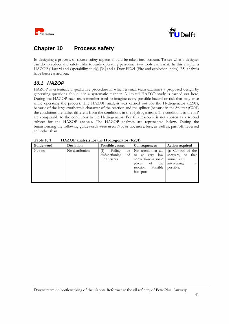
Downstream de-bottlenecking of the Naphta Reformer at the oil refinery of PetroPlus, Antwerp 41
Chapter 10 Process safety In designing a process, of course safety aspects should be taken into account. To see what a designer can do to reduce the safety risks towards operating personnel two tools can assist. In this chapter a HAZOP (Hazard and Operability study) [34] and a Dow FE&I (Fire and explosion index) [35] analysis have been carried out.
10.1 HAZOP HAZOP is essentially a qualitative procedure in which a small team examines a proposed design by generating questions about it in a systematic manner. A limited HAZOP study is carried out here. During the HAZOP each team member tried to imagine every possible hazard or risk that may arise while operating the process. The HAZOP analysis was carried out for the Hydrogenator (R201), because of the large exothermic character of the reaction and the splitter (because in the Splitter (C201) the conditions are rather different from the conditions in the Hydrogenator). The conditions in the HP are comparable to the conditions in the Hydrogenator. For this reason it is not chosen as a second subject for the HAZOP analysis. The HAZOP analyses are represented below. During the brainstorming the following guidewords were used: Not or no, more, less, as well as, part off, reversed and other than. Table 10.1 HAZOP analysis for the Hydrogenator (R201) Guide word Deviation Possible causes Consequences Action requiredNot, no No distribution
(1) Failing or disfunctioning of the sprayers
No reaction at all, or at very low conversion in some places of the reaction. Possible hot spots.
(a) Control of the sprayers, so that immediately intervening is possible.
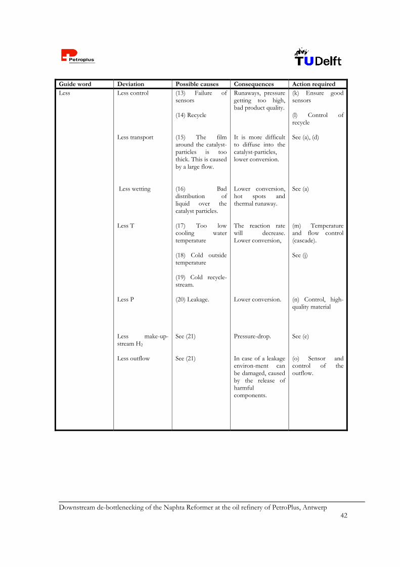
Downstream de-bottlenecking of the Naphta Reformer at the oil refinery of PetroPlus, Antwerp 42
Guide word Deviation Possible causes Consequences Action requiredLess Less control
Less transport Less wetting Less T Less P Less make-up-stream H2 Less outflow
(13) Failure of sensors (14) Recycle (15) The film around the catalyst-particles is too thick. This is caused by a large flow. (16) Bad distribution of liquid over the catalyst particles. (17) Too low cooling water temperature (18) Cold outside temperature (19) Cold recycle-stream. (20) Leakage. See (21) See (21)
Runaways, pressure getting too high, bad product quality. It is more difficult to diffuse into the catalyst-particles, lower conversion. Lower conversion, hot spots and thermal runaway. The reaction rate will decrease. Lower conversion, Lower conversion. Pressure-drop. In case of a leakage environ-ment can be damaged, caused by the release of harmful components.
(k) Ensure good sensors (l) Control of recycle See (a), (d) See (a) (m) Temperature and flow control (cascade). See (j) (n) Control, high-quality material See (e) (o) Sensor and control of the outflow.

Downstream de-bottlenecking of the Naphta Reformer at the oil refinery of PetroPlus, Antwerp 43
Guide word Deviation Possible causes Consequences Action requiredPart off Part of catalyst
functions Partly functioning of control-system.
See (2) (22) Failing of sensors or controllers.
Lower conversion and reaction-rate. Runaways, etc., dangerous situations.
p) Catalyst regeneration. (q) Be aware that the control system must not fail.
Reverse Reverse (recycle) flow
See (22) Undesirable reac-tions and mixtures that might be dangerous, less product, product of lower quality, unwanted cooling and unwanted heating.
(r) Flowcontrol andnon-return valves.
Table 10.2 HAZOP analysis for the Splitter (C201)
Guide word Deviation Possible causes Consequences Action requiredNot, no No inflow
No benzene in splitfow
(1) Failing of valves (2) No reformate production. (3) Accumulation in splitter (4) Temperature too high, benzene is in the topflow, or the opposite and benzene will be in the bottomflow,
No benzene flow to Hydrogenator, no splitting at all. Benzene in top- and bottomflow ad thus productspec is not reached.
(a) Control of the inflow <201>, <210>. (b) Control of the splitter (C201) (c) Temperature control (d) Flow control (e) Control of the composition of the flow.

Downstream de-bottlenecking of the Naphta Reformer at the oil refinery of PetroPlus, Antwerp 44
Guide word Deviation Possible causes Consequences Action requiredNot, no No separation
No reactor
(5) Temperature difference not big enough. (6) Accumulation of unwanted gasses in the Splitter. (7) Reactor-shutdown.
Benzenespec is not reached. No benzene flows to the reactor, so no reaction. The splitstream can’t flow to the reactor.
(f) Control of the outflows See (c) (g) Possible shutdown of the reactor. (h) Intermediate storage tank
More More T More P
(8) No or not enough cooling (9) High temperature outside (hot summer). (10) Accumulation.
Benzene over the top. Bad separation.
(i) Thermal isola-tion. (j) Check the coolingsystem (k) Recycle the top stream back into the splitter. (l) P-control.
Part off Control only partly functioning.
(11) Failing of some sensors or control functions.
The process can’t be controlled properly and dangerous situations can occur.
(m) Be aware that the control system must not fail.
10.2 Dow Fire & Explosion Index A Fire & Explosion Index (F&EI) assessment, according to the Dow Guide [35] has been completed. The F&EI calculation is a tool to help determine the areas of the greatest loss potential in a particular process, in this case the Debenzenizer. It also enables the prediction of the physical damage and business interruption that would occur in the event of an incident. The higher the F&EI, the more hazardous the process is.

Downstream de-bottlenecking of the Naphta Reformer at the oil refinery of PetroPlus, Antwerp 45
The first step is to determine which process units should be studied. Important factors for selecting pertinent process units include: Chemical energy potential (Material Factor) Quantity of hazardous material in the process unit Capital density (dollars per square foot) Process pressure and temperature Past history of problems that resulted in a fire and explosion incident Units critical to plant operation For this process, the Hydrogenator (R201)and the Splitter (C201) have been selected for evaluation, although the splitter does not have the greatest impact on the magnitude of any fire or explosion. The High Pressure Separator would be more hazardous with respect to process pressure and to the significant presence of hydrogen. However, calculating the F&EI for this unit would be a more or less repetition of the calculation for the reactor, since they operate at the same conditions and contain the same components. Besides, the Splitter also contains considerable amounts of combustible vapors and liquids. Moreover, it has a higher capital density than the High Pressure Separator. Therefore, the Splitter has been selected as the second unit to be evaluated with help of the F&EI, although its operation at ambient pressure and the absence of hydrogen in the column. Last but not least: the choice for the reactor is logically, since here the highest temperatures and pressures are obtained, hydrogen is present in excess, and the reaction that is performed is strongly exothermic. For the calculations, the material factor (MF) has been determined to be 21 for the Hydrogenator (R201) and 16 for the Splitter (C201) (since hydrogen is absent here). It is a measure of the intrinsic rate of potential energy release from fire or explosion produced by combustion or chemical reaction. The material factor is obtained from NF and NR, which are flammability and reactivity ratings from the National Fire Protection Association (NFPA). In fact, the F&EI is a type of ‘worst-case scenario’, since the MF and all penalties are taken to be that of the most hazardous substance/condition present in the process unit. Besides the determination of the MF, also penalties have to be ascribed to all possible process hazards. The hazards have been evaluated separately and then the penalties have been derived, using guidelines from [35]. The reasoning behind this derivation is briefly illustrated in Appendix 29. The results can be found in appendix 28. More explanation about the analysis is represented in appendix 29. The Hydrogenator (R201) has a F&EI of 107.4, which is classified as intermediate, and the Splitter (C201) has a F&EI of 81.3, which is classified as a moderate degree of hazard, based on the index.

Downstream de-bottlenecking of the Naphta Reformer at the oil refinery of PetroPlus, Antwerp 46
Chapter 11 Economy An important issue in deciding whether to make an investment or not, is to gain an insight in the economic value of the investment. After designing the Debenzenizer the economic value of this investment has been calculated. An investment has to be earned back and also a certain amount of profit has to be earned to make the investment worthwhile. In this chapter an economic evaluation has been made. The following economic information is presented: the investment, the operating costs, income and cash flow. The economic criteria used are: Rate of Return (ROR), Pay Out Time (POT) and the Discounted Cash Flow Rate of Return (DCFROR). All price data have been retrieved from [120, 366].
11.1 Total Investment Costs The total investment needed is the sum of the fixed capital and the working capital. The fixed capital is the total cost of the plant ready to start up. It includes the cost of design, all items of equipment, all piping instrumentations and control systems, buildings and structures and auxiliary facilities such as utilities. Working capital is the additional investment needed to start the plant up and operate it to the point when income is earned. The working capital includes the costs of start-up, initial catalyst charges, raw materials and intermediates in the process, finished product inventories and funds to cover outstanding accounts from customers. The working capital is taken 15% of the fixed capital. 11.1.1 Fixed capital Costs The fixed capital is calculated using the Lang factorial method. According to this method the fixed capital cost of the project is given by the following equation:
LCf f Ce (11. 1)
In which: Cf Fixed capital costs
Ce Total delivered costs of all the equipment items (i.e. total equipment costs) fL ‘Lang factor’ [20].
Calculations have been performed and the results are presented in Table 11.1. A brief explanation follows below. First the purchase costs of the major equipment are estimated. The prices of the equipment are listed in Appendix 30, prices are estimated with help of [1]. The estimated purchased cost of major equipment (PCE) is US$ 0.810 million. To calculate the physical plant cost (PPC), PCE is multiplied by the sum of the different Lang factors for: equipment erection, piping, instrumentation and electrical [20 ]. The physical plant costs are US$ 1.941 million. Correcting this PPC-value for design, engineering and contingency costs provides the fixed capital costs, which make: US$ 2.722 million. An overview of these calculations is presented in Table 11.1.
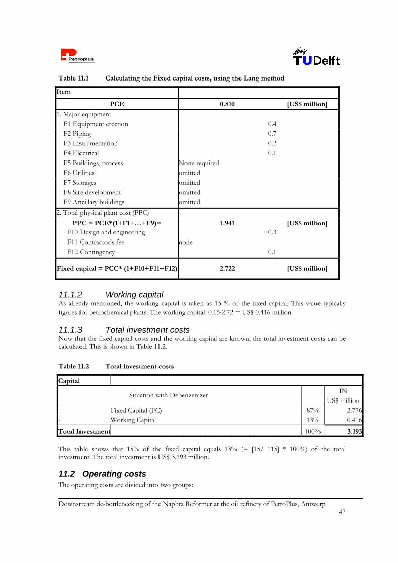
Downstream de-bottlenecking of the Naphta Reformer at the oil refinery of PetroPlus, Antwerp 47
Table 11.1 Calculating the Fixed capital costs, using the Lang method
Item
PCE 0.810 [US$ million]
1. Major equipment F1 Equipment erection 0.4 F2 Piping 0.7 F3 Instrumentation 0.2 F4 Electrical 0.1 F5 Buildings, process None required F6 Utilities omitted F7 Storages omitted F8 Site development omitted F9 Ancillary buildings omitted 2. Total physical plant cost (PPC)
PPC = PCE*(1+F1+…+F9)= 1.941 [US$ million] F10 Design and engineering 0.3 F11 Contractor’s fee none F12 Contingency 0.1
Fixed capital = PCC* (1+F10+F11+F12) 2.722 [US$ million]
11.1.2 Working capital As already mentioned, the working capital is taken as 15 % of the fixed capital. This value typically figures for petrochemical plants. The working capital: 0.152.72 = US$ 0.416 million. 11.1.3 Total investment costs Now that the fixed capital costs and the working capital are known, the total investment costs can be calculated. This is shown in Table 11.2.
Table 11.2 Total investment costs
Capital
Situation with Debenzenizer IN US$ million
- Fixed Capital (FC) 87% 2.776- Working Capital 13% 0.416
Total Investment 100% 3.193 This table shows that 15% of the fixed capital equals 13% (= [15/ 115] * 100%) of the total investment. The total investment is US$ 3.193 million.
11.2 Operating costs The operating costs are divided into two groups:
Downstream de-bottlenecking of the Naphta Reformer at the oil refinery of PetroPlus, Antwerp 48
1) Fixed operating costs: costs that do not vary with production rate. These are bills that have to be paid whatever quantity produced.
2) Variable operating costs: costs that are dependent on the amount of product produced. The fixed costs are: Maintenance Operating labor Laboratory Supervision Plant overhead Capital charges Insurance Local taxes Royalties
The variable costs are the following: Raw materials Miscellaneous operating materials Utilities Shipping and packaging As is mentioned in Chapter 3 the battery limits over which the economic margins are calculated are: from the intake before the Naphta Splitter to the resulting product streams: <102>, <111>, <112>, <114>, <216>, <229>, <230> and <231>. The present situation is referred as the nowadays operation of the plant. The split ratio of the NS is of importance, i.e. in present situation 50/50 LDN/HDN ratio. Of course at the moment no Debenzenizer is present. For the situation the Debenzenizer is installed, the NS operates with a split ratio of 30/70 LDN/HDN. In all calculations for the economic evaluation the difference between the results in both situations is taken. Otherwise it would still not be possible to draw any conclusions about the benefit of installing the Debenzenizer and a fair economic evaluation could not be made. In the Table 11.3 – 11.7 price data are presented.
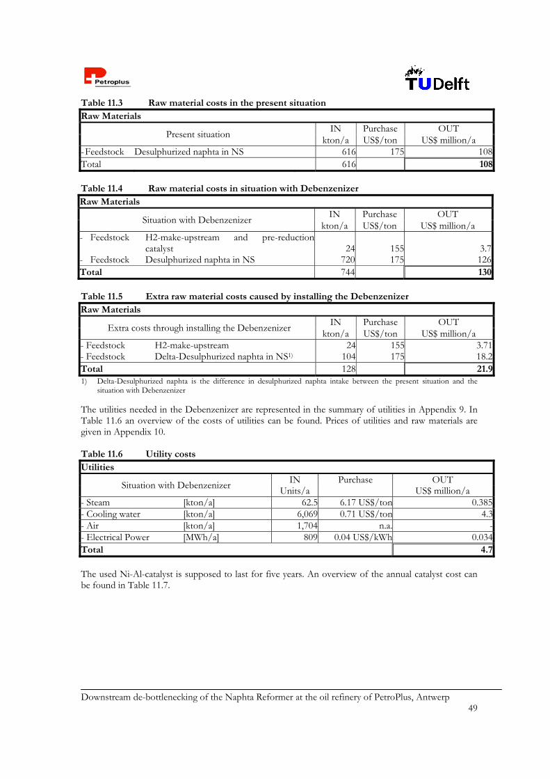
Downstream de-bottlenecking of the Naphta Reformer at the oil refinery of PetroPlus, Antwerp 49
Table 11.3 Raw material costs in the present situation Raw Materials
Present situation IN Purchase OUT
kton/a US$/ton US$ million/a - Feedstock Desulphurized naphta in NS 616 175 108Total 616 108 Table 11.4 Raw material costs in situation with Debenzenizer Raw Materials
Situation with Debenzenizer IN Purchase OUT
kton/a US$/ton US$ million/a - Feedstock H2-make-upstream and pre-reduction
catalyst 24 155 3.7- Feedstock Desulphurized naphta in NS 720 175 126Total 744 130 Table 11.5 Extra raw material costs caused by installing the Debenzenizer Raw Materials
Extra costs through installing the Debenzenizer IN Purchase OUT
kton/a US$/ton US$ million/a- Feedstock H2-make-upstream 24 155 3.71- Feedstock Delta-Desulphurized naphta in NS1) 104 175 18.2Total 128 21.91) Delta-Desulphurized naphta is the difference in desulphurized naphta intake between the present situation and the
situation with Debenzenizer
The utilities needed in the Debenzenizer are represented in the summary of utilities in Appendix 9. In Table 11.6 an overview of the costs of utilities can be found. Prices of utilities and raw materials are given in Appendix 10. Table 11.6 Utility costs Utilities
Situation with Debenzenizer IN Purchase
OUT Units/a US$ million/a
- Steam [kton/a] 62.5 6.17 US$/ton 0.385- Cooling water [kton/a] 6,069 0.71 US$/ton 4.3- Air [kton/a] 1,704 n.a. -- Electrical Power [MWh/a] 809 0.04 US$/kWh 0.034Total 4.7 The used Ni-Al-catalyst is supposed to last for five years. An overview of the annual catalyst cost can be found in Table 11.7.
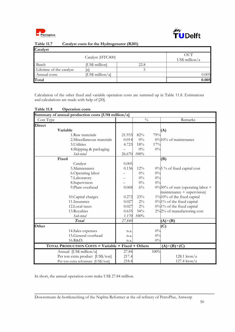
Downstream de-bottlenecking of the Naphta Reformer at the oil refinery of PetroPlus, Antwerp 50
Table 11.7 Catalyst costs for the Hydrogenator (R201) Catalyst
Catalyst (HTC400) OUT
US$ million/a - Batch [US$ million] 22.8 - Lifetime of the catalyst [a] 5 - Annual costs [US$ million/a] 0.005Total 0.005 Calculation of the other fixed and variable operation costs are summed up in Table 11.8. Estimations and calculations are made with help of [20]. Table 11.8 Operation costs Summary of annual production costs [US$ million/a]
Cost Type % Remarks Direct Variable (A) 1.Raw materials 21.933 82% 79% 2.Miscellaneous materials 0.014 0% 0%10% of maintenance 3.Utilities 4.723 18% 17% 4.Shipping & packaging – 0% 0% Sub-total 26.670 100%
Fixed (B) Catalyst 0.005
5.Maintenance 0.136 12% 0%5 % of fixed capital cost 6.Operating labor – 0% 0% 7.Laboratory – 0% 0% 8.Supervision – 0% 0%
9.Plant overhead
0.068 6% 0%50% of sum (operating labor +
maintenance + supervision) 10.Capital charges 0.272 23% 1%10% of the fixed capital 11.Insurance 0.027 2% 0%1% of the fixed capital 12.Local taxes 0.027 2% 0%1% of the fixed capital 13.Royalties 0.635 54% 2%2% of manufactoring cost Sub-total 1.170 100% Total 27.840 (A)+(B) Other (C) 14.Sales expenses n.a. 0% 15.General overhead n.a. 0% 16.R&D. n.a. 0%
TOTAL PRODUCTION COSTS = Variable + Fixed + Others (A)+(B)+(C) Annual [US$ million/a] 27.84 100% Per ton extra product [US$/ton] 217.4 128.1 kton/a Per ton extra reformate [US$/ton] 218.4 127.4 kton/a In short, the annual operation costs make US$ 27.84 million.

Downstream de-bottlenecking of the Naphta Reformer at the oil refinery of PetroPlus, Antwerp 51
11.3 Income and Cash flow The main product is the reformate. Other products are LDN, LPG and H2 rich fuel gas. Important is the difference between the income in the present situation and the income in the situation with the Debenzenizer installed. In fact this difference is the amount of money the investment will pay. For this reason the income of the different products in the present situation is also summed up. The results from Table 11.9 conclude an income of US$ 29 million /a. Table 11.9 Income due to the Debenzenizer
Present situation With Debenzenizer [kton/a] Ec. Val.1)
[US$/ton]Ec. Val. 1)
[US$ million/a] [kton/a] Ec. Val.1)
[US$/ton] Ec. Val.1)
[US$ million/a] Products
LDN 308 140 43.1 222 140 31.1 LPG 36.2 100 3.6 68 100 6.76 Reformate 247 215 53.2 375 220 82.6 Rich H2 FG 24.3 155 3.77 79.5 155 12.3Total [US$ million/a] 104 133Difference in total income[US$ million/a]
29
1) Ec. Val. = Economic Value
The net cash flow before tax (NCF) is the difference between the annual income and the annual operating costs. In this case: NCF = 29.00 – 27.84 = US$ 1.16 million /a.
11.4 Economic evaluation This section discusses the ROR, the POT and the DCFROR (=earning power). They are criteria for the economic evaluation of the project. First estimations for income tax and economic plant life have to be made. The income tax is set at 18 % [1] and the economic plant life is estimated at 27 years, including a year of construction and a year of breakdown. First, the DCFROR is calculated. The Discounted Cash Flow (DCF)-analysis is used to calculate the present value of future earnings. While performing this analysis the Net Present Value (NPV) is calculated for various interest rates. The rate at which the NPV is zero is called the DCFROR. The DCFROR is a measure of the maximum rate of interest that the project could pay and still break-even by the end of the project-life (the so-called economic plant life). The Eq. 11.2 is used to calculate the DCFROR.
n=t
nn=1 '
NFVΣ = 0
1+r (11. 2)
In which r’ Discounted cash flow rate of return [-] NFV Net future Value [-] t Life of the project [year] n Time passed after start of construction [year]
The calculation of the DCFROR is a trial-and-error-process and can be found in Appendix 31. The first estimate for r’ is 10%. This value turned to be too low, because the NPV in the 27th year would becomes – US$ 7.3 million. By trial-and-error a DCFROR of 36.95% is found. This is a reasonable
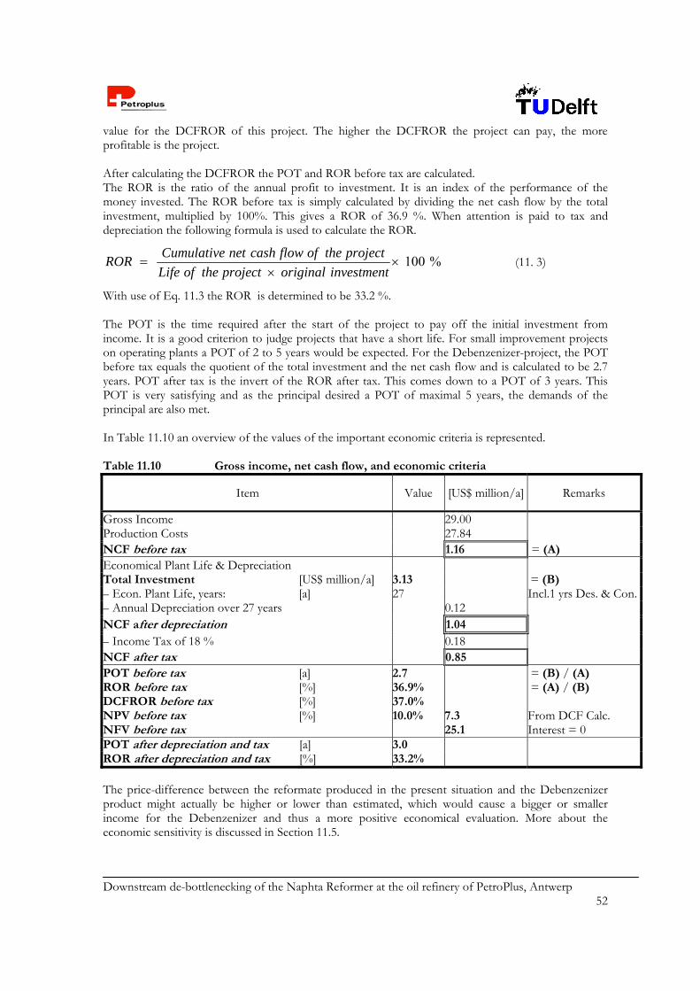
Downstream de-bottlenecking of the Naphta Reformer at the oil refinery of PetroPlus, Antwerp 52
value for the DCFROR of this project. The higher the DCFROR the project can pay, the more profitable is the project. After calculating the DCFROR the POT and ROR before tax are calculated. The ROR is the ratio of the annual profit to investment. It is an index of the performance of the money invested. The ROR before tax is simply calculated by dividing the net cash flow by the total investment, multiplied by 100%. This gives a ROR of 36.9 %. When attention is paid to tax and depreciation the following formula is used to calculate the ROR.
100 %
Cumulative net cash flow of the projectROR
Life of the project original investment
(11. 3)
With use of Eq. 11.3 the ROR is determined to be 33.2 %. The POT is the time required after the start of the project to pay off the initial investment from income. It is a good criterion to judge projects that have a short life. For small improvement projects on operating plants a POT of 2 to 5 years would be expected. For the Debenzenizer-project, the POT before tax equals the quotient of the total investment and the net cash flow and is calculated to be 2.7 years. POT after tax is the invert of the ROR after tax. This comes down to a POT of 3 years. This POT is very satisfying and as the principal desired a POT of maximal 5 years, the demands of the principal are also met. In Table 11.10 an overview of the values of the important economic criteria is represented. Table 11.10 Gross income, net cash flow, and economic criteria
Item Value [US$ million/a] Remarks
Gross Income 29.00 Production Costs 27.84 NCF before tax 1.16 = (A) Economical Plant Life & Depreciation Total Investment [US$ million/a] 3.13 = (B) – Econ. Plant Life, years: [a] 27 Incl.1 yrs Des. & Con.– Annual Depreciation over 27 years 0.12 NCF after depreciation 1.04 – Income Tax of 18 % 0.18 NCF after tax 0.85 POT before tax [a] 2.7 = (B) / (A) ROR before tax [%] 36.9% = (A) / (B) DCFROR before tax [%] 37.0% NPV before tax [%] 10.0% 7.3 From DCF Calc. NFV before tax 25.1 Interest = 0 POT after depreciation and tax [a] 3.0 ROR after depreciation and tax [%] 33.2% The price-difference between the reformate produced in the present situation and the Debenzenizer product might actually be higher or lower than estimated, which would cause a bigger or smaller income for the Debenzenizer and thus a more positive economical evaluation. More about the economic sensitivity is discussed in Section 11.5.
Downstream de-bottlenecking of the Naphta Reformer at the oil refinery of PetroPlus, Antwerp 53
11.5 Sensitivity analysis A sensitivity analysis has been carried out to observe how the economic criteria react to changes in costs for the fixed capital, raw materials and utilities and the price of the reformate. In this section a short overview of the results generated by this analysis is given. Details are represented in appendix 34. For the analysis the fixed capital was increased and decreased with 10%. The economic criteria turned out not to be very sensitive to changes in the fixed capital. The investment with respect to the turnover is small. Therefore the economic criteria are not much sensitive for the price of fixed costs. On the other hand the economic criteria are very sensitive to changes in the prices of raw materials purchased and of the reformate sold. For example an increase of 5% of the raw material costs lead to an increase in the POT with 319 years. In case of a 5% – increase in price of the reformate leads to a decrease in POT of 2.5 years. This strong sensitivity is because there is only a small difference in values of the raw materials and products. Varying the value of only one of these can make the cash flow change from positive to negative. In reality the prices of raw material and products change simultaneously, since they occupy the same economic market. Nevertheless, a small change in price per ton causes a big change in the cash flow, because of the large annual throughput. The values of the purchased utilities and of the reformate are both increased and decreased with 5 %. As a result the value of the utilities does not have a very big influence on the economic criteria.
Downstream de-bottlenecking of the Naphta Reformer at the oil refinery of PetroPlus, Antwerp 54
Chapter 12 Conclusions and recommendations Based on a detailed knowledge gathered during this down-stream design project, a review of the strengths and weaknesses of the Debenzenizer is given in this chapter. On the basis of this review, a number of recommendations has been done. The first conclusion that can be drawn is that the Debenzenizer is able to fulfill all specifications that were given by the principal. In short, these were: Benzene content of the reformate 1 vol%, Naphta Split Ratio = 30/70 (LDN/HDN), RON = 99.5. These specifications can be summarized as an increase of the total reformate production, while indeed meeting the current benzene specs. This is said especially with respect to the benzene content, which is 1.5 vol% in the present situation. With the Debenzenizer a final benzene concentration of 0.59 vol% is realized. At a 30/70 operation of the Naphta Splitter the throughput of the original reformate is 405 kton/a. The Debenzenizer realizes a total reformate stream of 375 kton/a. This seems to be a loss of approximately 2.35 %, however, one must not forget that compared to the present situation this is a significant increase (~37%). The ‘loss’ of reformate can be translated into an increase of LDN and FG production, which also have attractive commercial values. Cost calculations on the Debenzenizer show out that raw materials and utilities are the major cost items. With the Debenzenizer, a positive cash flow after tax of US$ 0.85 million is realized, compared to the original situation. The related Pay Out Time after tax is 3 years, with a DCFROR of 37.0 %. These economic criteria are based on a price difference the intake and outgoing reformate of 5 US$/ton. The HTC400 catalyst, which is selected for the Debenzenizer, is a flexible catalyst in the sense that it is also able to hydrogenate other aromatic compounds, like toluene and xylene. This may be favorable, in case of further restrictions on the aromatic content of gasoline. Besides, the fact that the Debenzenizer is an end-of-pipe process creates the advantage that in case of any failure, the original process will not be affected. Of course, the benzene content will then temporarily not meet the spec anymore. Another comment on the Debenzenizer is that this process creates minimal waste streams. Besides the main product, reformate, only LDN and hydrogen-rich streams are produced, which are not regarded as waste, but as valuable products. In this context, the choice for the Debenzenizer as the selected process option is plausible, compared to for example an extraction procedure, which would lead to more contaminated outgoing streams. For the purpose of evaluating the process safety, a HAZOP analysis and F&EI calculations have been performed. The results of the latter show that the Debenzenizer is a process with a moderate to intermediate degree of hazard. Conclusions with respect to the weaknesses of the Debenzenizer consist of two main considerations. The first concerns the strong exothermic hydrogenation reaction. It is important to control the temperature in the reactor in order to prevent a thermal runaway. In this design, three measures have been taken. First, the benzene mixture in the reactor is diluted by an internal recycle of the reactor
Downstream de-bottlenecking of the Naphta Reformer at the oil refinery of PetroPlus, Antwerp 55
effluent. Second, the reaction mixture is cooled by means of a quench of the hydrocarbon mixture above the second catalyst bed. Third, a reactor-cooling jacket has been designed. To prevent the formation of hot spots, a layer of ceramic balls has been designed on top of the catalyst bed to ensure a good liquid distribution. The second weakness concerns the temperature in the Top of the Splitter. Cooling water is used for cooling this stream down to 298 K. This may cause complications, when the inlet temperature of the cooling water is higher than expected. A number of recommendations has been done with respect to this design project. In the next survey first recommendations are given with respect to the mentioned process weaknesses. These are completed with additional recommendations, which arose during the design. The feed to the reactor is diluted by a recycle of the hydrocarbon effluent. Another option was to
operate the Splitter in such a way, that it releases only two streams, one through the Top, containing the majority of benzene and one through the Bottom. In that case, the fresh reactor feed is diluted on beforehand. As a result the temperature rise in the reactor will be slower and thus a safer operation is possible, since only benzene will be hydrogenated. Moreover, the design of a shorter column is allowed, which results in lower equipment costs. Due to a lack of time needed for re-simulation and resizing the reactor and additional equipment, this idea has not been elaborated yet. But it certainly is worthwhile to spend more attention to.
Another option is to design two separate, but shorter columns. This is an option in case a column height of 30 m is undesired. The first column then releases the benzene-rich fraction together with the lighter fractions (<207>) over the top and the current Bottom stream (<209>) over its bottom. The second column is used to separate the benzene-rich fraction from the lighter components, i.e. <207>. Thereby the benzene-rich fraction leaves the column over the bottom.
Fortunately, the low temperature at the Top is handled. A cooling area of 441 m2 is required and therefore the selection for finned tube heaters has been made. However, a more plausible solution is to deal with this complication at its origin, thus to design the Splitter differently, such that the Top temperature becomes higher and can be more easily cooled. Implementation of the first recommendation would meet this constraint. Besides, the column dimensions can probably be designed to be smaller, which results in lower equipment costs.
Another recommendation concerning the Top temperature lies in increasing the column operating pressure. This is a common approach to situations where the top of a column is difficultly cooled, because of a small temperature difference with respect to cooling water temperatures. Increasing the column operating pressure reduces the vapor fraction at the trays and allows a higher temperature at the top. In the Aspen simulation this is not done, because of complications with respect to the resulting simulation results.
The reactor effluent is cooled by air down to 333 K and further with water to 293 K. The bottom stream is cooled with water from 370 K to 313 K (E205). An alternative is to cover part of this cooling duty with the use of air, because of the low costs involved. Recommended is to look further into this option to see whether it is worth the additional investments and thus leads to overall cost reduction.
The principle of the Debenzenizer lies in the hydrogenation of benzene by treating a relatively small liquid volume. The selection for this option is detailedly explained in chapter two. Other generated process options have been rejected, but it is worthwhile to pick out the attractive elements and to pay attention to possible integration. If future legislation on the aromatic content of gasoline is further restricted, the Debenzenizer can easily be adjusted, since the selected catalyst can also hydrogenate other aromatic compounds. However, the RON of the reformate will decrease and be off-spec. The solution for this can be found by designing an additional isomerization unit, in which linear hydrocarbons are converted into their branched isomers, thereby enhancing the RON. At this moment, this approach is redundant, since the Debenzenizer can fulfill the current specs.
Downstream de-bottlenecking of the Naphta Reformer at the oil refinery of PetroPlus, Antwerp 56
Another recommendation is the implementation of catalytic distillation. This is an advanced alternative of the Debenzenizer, which implies in situ hydrogenation of benzene in the column, using structured packing loaded with catalyst. Unfortunately, at the moment this technology is still at the beginning stage of its development and for the purpose of this design project it might be an approach, which is too risky. It is advisable, however, to take this option into account for the final decision,
The reaction kinetics have been derived from [3, 5]. The data were based on experiments with a fed-batch reactor. According to the authors [377], it is allowed to describe continuous operation by use of the same kinetics. It is recommended to confirm this assumption by further research on this topic, may the Debenzenizer be seriously considered as the final solution.
It is recommended to as do a simulation in Aspen with a Plug Flow Reactor (PFR) as model for R201. In that case, the hydrogen gas and the benzene liquid flows have to be combined before intake, since in Aspen the PFR has only one intake stream. Further, the quench of hydrocarbons is then implemented by taking one PFR model for every bed.
The reformate as produced with the Debenzenizer contains 0.59 vol% benzene and the maximum allowable content is 1 vol%. The hydrogenation of benzene leads to a decrease of the RON. The reformate throughput is restricted by the RON specification at 99.5. When less conversion of benzene takes place, the total reformate throughput increases. The reason for this is that it is allowed to blend a larger part of the Top stream into the final product, before the RON reaches 99.5. With respect to the allowed benzene content, the Debenzenizer actually functions better than expected. However, with respect to the reformate throughput and thus the annual income, the profits have not been optimized yet. It is recommended to do this and to optimize the blending section.

Downstream de-bottlenecking of the Naphta Reformer at the oil refinery of PetroPlus, Antwerp 57
List of symbols
Symbol Description Units CP0 Change in specific heat of reaction at 298 K J/mole.J
CP0 Change in specific heat of reaction J/mole.K
G Change in Gibbs free energy J/mole GF Gibbs free energy of formation of a component J/mole
H Differential heat of solution J/mole
H0 Enthalpy of reaction J/mole
HF Enthalpy of formation of a component J/mole
i Stoichiometric coefficient of component i -
RG00 Gibbs free energy of reaction at 298 K J/mole
RH00 Enthalpy of reaction at 298 K J/mole
RS00 Entropy of reaction J/mole.K
T Temperature increase (Toutlet – Tinlet) K
Tlm Logarithmic mean temperature difference K
x Length interval m A Heat exchange area of total reactor m2
Aa Active area m2
Aap Area under apron m2 Ac Column area m2 Ad Cross-sectional area of downcomer m2 Ah Hole area m2 Am Smallest of Ad and Aap m2 An Net area m2 Aslice Heat exchange area of slice m2
C1 Concentration of H2 at T = T1, p = p1 C2 Concentration of H2 at T = T2, p = p2 = p1 cA Concentration benzene mole/m3 cbenzene Concentration benzene mole/m3 cH Concentration hydrogen mole/m3 CP Specific heat of a component J/mole.K cp,gas Heat capacity of gas J/m3.K Cp,i0 Heat capacity of component i J/mole.K cp,l Heat capacity of liquid J/m3.K D Diameter of reactor m Dc Diameter of column m dh Hole diameter mm EA Activation energy J/mole FLV Liquid-vapor flow factor - H Enthalpy W H_in Enthalpy of ingoing streams W H_out Enthalpy of outgoing streams W hap Downcomer pressure drop mm hb Downcomer back-up mm hbc Clear liquid back-up m hd Pressure drop through the dry plate mm
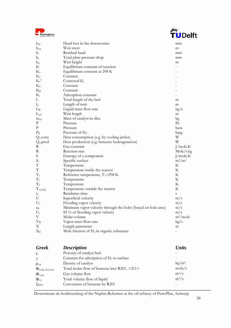
Downstream de-bottlenecking of the Naphta Reformer at the oil refinery of PetroPlus, Antwerp 58
hdc Head loss in the downcomer mm how Weir crest m hr Residual head mm ht Total plate pressure drop mm hw Weir height m K Equilibrium constant of reaction - K1 Equilibrium constant at 298 K - K1 Constant - K1’ Corrected K1 - K2 Constant - KB Constant - Ki Adsorption constant - L Total length of the bed m lw Length of weir m LW Liquid mass flow-rate kg/s Lwd Weir length m mcat Mass of catalyst in slice kg P Pressure Pa P Pressure bara PB Pressure of H2 barg Q_cons Heat consumption (e.g. by cooling jacket) W Q_prod Heat production (e.g. benzene hydrogenation) W R Gas constant J/mole.K R Reaction rate Mole/s.kg S Entropy of a component J/mole.K Sv Specific surface m2/m3 T Temperature K T Temperature inside the reactor K T1 Reference temperature, T1=298 K K T1 Temperature K T2 Temperature K Toutside Temperature outside the reactor K tr Residence time s U Superficial velocity m/s Uf Flooding vapor velocity m/s uh Minimum vapor velocity through the holes (based on hole area) m/s Uv 85 % of flooding vapor velocity m/s V Molar volume m3/mole VW Vapor mass flow-rate kg/s X Length parameter m XB Mole fraction of H2 in organic substance -
Greek Description Units Porosity of catalyst bed - Constant for adsorption of H2 to surface - cat Density of catalyst kg/m3
mole, benzene Total molar flow of benzene into R201, <211> mole/s
v,gas Gas volume flow m3/s
v,l Total volume flow of liquid m3/s ξR201 Conversion of benzene by R201 -

Downstream de-bottlenecking of the Naphta Reformer at the oil refinery of PetroPlus, Antwerp 59
Viscosity Pa.s Summation - V Density of vapor kg/m3
L Density of liquid kg/m3
Liquid surface tension N/m v,vapor Volume flow of vapor [m3/s] m3/s
c Angle subtended by chord º
Difference -
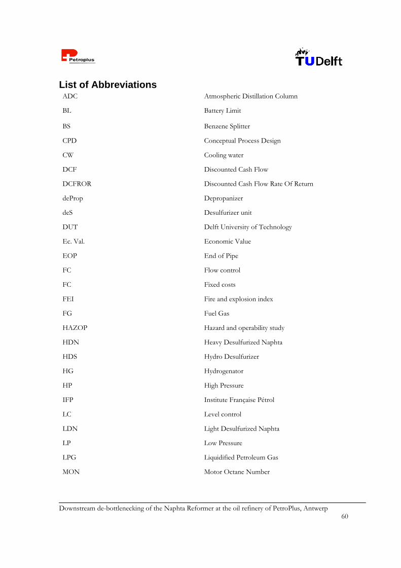
Downstream de-bottlenecking of the Naphta Reformer at the oil refinery of PetroPlus, Antwerp 60
List of Abbreviations ADC Atmospheric Distillation Column
BL Battery Limit
BS Benzene Splitter
CPD Conceptual Process Design
CW Cooling water
DCF Discounted Cash Flow
DCFROR Discounted Cash Flow Rate Of Return
deProp Depropanizer
deS Desulfurizer unit
DUT Delft University of Technology
Ec. Val. Economic Value
EOP End of Pipe
FC Flow control
FC Fixed costs
FEI Fire and explosion index
FG Fuel Gas
HAZOP Hazard and operability study
HDN Heavy Desulfurized Naphta
HDS Hydro Desulfurizer
HG Hydrogenator
HP High Pressure
IFP Institute Française Pétrol
LC Level control
LDN Light Desulfurized Naphta
LP Low Pressure
LPG Liquidified Petroleum Gas
MON Motor Octane Number
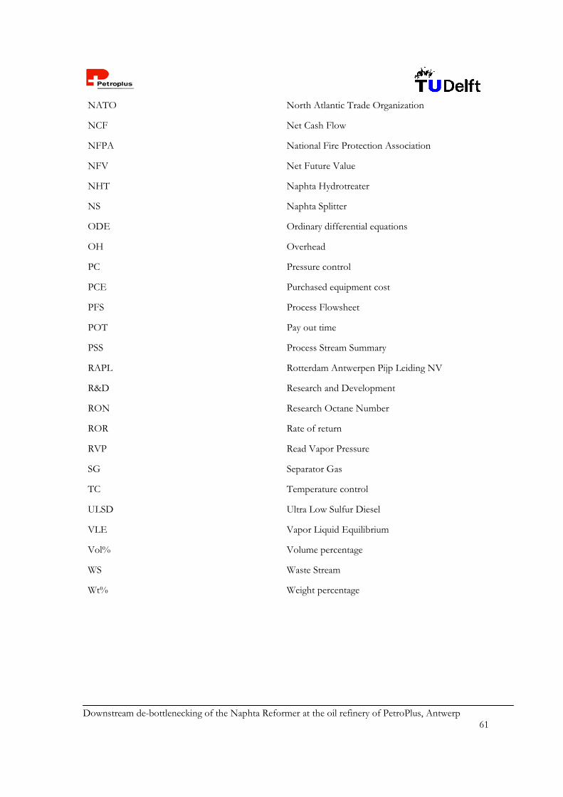
Downstream de-bottlenecking of the Naphta Reformer at the oil refinery of PetroPlus, Antwerp 61
NATO North Atlantic Trade Organization
NCF Net Cash Flow
NFPA National Fire Protection Association
NFV Net Future Value
NHT Naphta Hydrotreater
NS Naphta Splitter
ODE Ordinary differential equations
OH Overhead
PC Pressure control
PCE Purchased equipment cost
PFS Process Flowsheet
POT Pay out time
PSS Process Stream Summary
RAPL Rotterdam Antwerpen Pijp Leiding NV
R&D Research and Development
RON Research Octane Number
ROR Rate of return
RVP Read Vapor Pressure
SG Separator Gas
TC Temperature control
ULSD Ultra Low Sulfur Diesel
VLE Vapor Liquid Equilibrium
Vol% Volume percentage
WS Waste Stream
Wt% Weight percentage

Downstream de-bottlenecking of the Naphta Reformer at the oil refinery of PetroPlus, Antwerp 62
References 1. Personal contact with P. Ham and A. v/d Griendt from Petroplus Antwerp. 2. www.ifpna.com 3. Kinetics and Mechanism of Liquid-Phase hydrogenation, Kinetics and Catalysis, 36(1), 61-68 (1995) 4. Mechanism of the Liquid-Phase Hydrogenation of the Benzene Ring, Kinetics and Catalysis, 30(3),
555-561 (1989) 5. Liquid-Phase Hydrogenation Kinetics of Aromatic Hydrocarbon Mixtures, Industrial and Engineering
chemistry research, 36 (6): 2101-2109 JUN 1997. 6. Kinetics of the Liquid-Phase Hydrogenation of Benzene and Some Monosubstituted
Alkylbenzenes over a Nickel Catalyst, Industrial and Engineering chemistry research, 35 (6): 1824-1833. 7. See, S.T., Collegedictaat petroleumconversie, TNW, TUDelft (1992) 8. www.uop.com 9. Comyns, A.E., Encyclopedic dictionary of named processes in chemical technology, CRC Press,
Boca Raton, Florida, second edition (1999) 10. http://193.130.109.153/cgi-
bin/frameset.cgi?start=http://www.shellchemicals.com/chemicals/geography/manufacturing/site/1,1157,31-page_id=126,00.html
11. http://www.uop.com/techsheets/sulfolane.pdf 12. http://fih.hsl.nl/ct2/isomerisatie.html, http://www.uop.com/techsheets/par_isom.pdf 13. http://www.r-t-o-l.com/learning/studentsguide/isom.htm,
http://www.uop.com/techsheets/Carom%20ps.pdf 14. Moulijn, J.A. e.a., Chemical Process Technology, John Wiley and Sons, Chichester (2001) 15. Chao, J., Benzene key chemicals data books, Thermodynamics Research center, Texas (1978) 16. Douglas, J.M., Conceptual Design of Chemical Processes, McGrawHill International Editions
(1988) 17. Personal contact with Dr. Martin Lok, research associate at ICI Synetix 18. Personal contact with M. Sc. Bram Hoffer, DUT 19. Smith, J.M., Introduction to Chemical Engineering Thermodynamics, McGraw-Hill, 5th ed. (1996) 20. Sinott, R.K., Coulson and Ricardson’s chemical engineering vol. 6, third ed., Butterworth-
Heinemann, Oxford (1999) 21. Aspen Plus User Guide, Release 9, Volume 1 22. Gmehling, J. Vapor-liquid equilibrium data collection, Dechema Chemistry data series,
Frankfurt/Main, Germany (1980) 23. Lide, D.R., Handbook of Chemistry and Physics, 81st edition, Boca Raton (2000-2001) 24. Vargaftik, N.B., Handbook of Physical Properties of Liquids and Gases, 3rd edition, Begell house,
New York (1996) 25. Dean, John A., Lange's Handbook of Chemistry, McGraw-Hill, New York (1992) 26. Glasstone, S. Textbook of Physical Chemistry, Van Nostrand, New York (1947) 27. Atkins, P.W., Physical Chemistry, Oxford University Press, 5th edition, Oxford (1993), Pg 218 28. Stephen, H. and Stephen, T., Solubility’s of inorganic and organic compounds, Volume 1, part 1,
Pergamon Press, Oxford (1963) 29. Stephanopoulos, G., Chemical Process Control, Prentice Hall International, New Jersey (1984) 30. Yaws, C.L., Chemical Properties Handbook, McGraw-Hill, New York (1999) 31. Scarlett, B. et al, Deeltjestechnologie I, Vakgroep Chemische Proces Technologie, DUT (1997) 32. Branan, C. R., Rules of Thumb for Chemical Engineers, Gulf Publishing Company, Houston
(1994) 33. Chemiekaarten, 16e edition (2001) 34. Pasman, H.J., Lemkowitz, S.M., Dictaat Chemical risk management, Delft (2001) 35. Dow’s Fire & Explosion Index Hazard Classification Guide, 7th ed., AIChe New York (1994) 36. DACE-price book, by webci, wubo, H.J.M. Klein Gunnewiek, 21st ed., November 2000 37. Personal contact with Professor T. Salmi, University of Oulu, Finland.
Downstream de-bottlenecking of the Naphta Reformer at the oil refinery of PetroPlus, Antwerp 63

Downstream de-bottlenecking of the Naphta Reformer at the oil refinery of PetroPlus, Antwerp 64
Appendices