concrete masonry - ncma-br.org · concrete masonry designs ihardscape issue ... and distributed to...
TRANSCRIPT

MasonryConcrete
D e s i g n sMasonry
AIA Continuing Education Learning Program page 23
HArdsCAPE IssuE
special Considerations for Tall Wallspage 4
Herrick street Bridgepage 6
TEK 14-18B seismic design and detailing requirements for Masonry structures page 9
Fences, railings & Traffic Barrierspage 18
s E P T E M B E r 2 0 0 9
A PublicAtion of the
www.ncMA.oRg


Concrete
concrete Masonry Designs I Hardscape Issue n 3
MasonryD e s i g n s
MasonryF E A T u r E s
4special considerations for tall walls
6herrick street bridge
18fences, Railings & traffic barriers
d E P A r T M E N T s
9 teK 14-18b seismic Design and Detailing Requirements for Masonry structures
22 Detail of the Month
23 AiA continuing education learning Program
Concrete Masonry Designs magazine show- cases the qualities and aesthetics of design and construction using concrete masonry.
Concrete Masonry Designs is devoted to design techniques using standard and architectural concrete masonry units, concrete brick, unit concrete pavers, segmental retaining walls, and other concrete masonry products around the world. We welcome your editorial comments, ideas, and submissions.
Copyright 2009 by the National Concrete Masonry Association. All rights reserved. Contents may not be reprinted or reproduced without written permission from NCMA.
Concrete Masonry Designs is published monthly by the National Concrete Masonry Association (NCMA), and distributed to advance and support the concrete masonry and hardscape industry and public interest.
Send address corrections and subscription inquiries to: NCMA Sales and Marketing Department13750 Sunrise Valley DriveHerndon, VA 20171-4662703-713-1900 Fax 703-713-1910www.ncma.org
Publisher: Robert D. Thomas
editor: Mary Arntson-Terrell, [email protected]
Associate editors: Dennis W. Graber, P.E. Harry W. Junk Gabriela Mariscal
Advertising: Heidi Weiss, [email protected]
h a r d s c a p e i s s u e I September 2009
Cover image and above image courtesy of CornerStone Wall Solutions.

9/ 09 4
aller walls often have special concerns that are not significant issues for shorter walls. Given their height, taller walls will influence and be influenced by a much larger portion of a site, so project design professional(s) must pay careful
attention to site conditions well beyond the loca-tion of the SRW wall face and well below the SRW system. Layout issues, such as the wall batter and geosynthetic reinforcement lengths become more sig-nificant with tall walls that lose more space and need more space for longer reinforcement lengths.
One of the primary structural concerns for taller walls is the post-construction settlement of the rein-forced soil (infill). Even well-compacted, high-quality granular backfill will experience some post-construc-tion settlement. Even if the percentage of backfill set-tlement to fill height is less than one percent, this can yield significant settlement in a 30, 40 or 50 ft (9.14, 12.19 or 15.24 m) high wall. Total settlement of wall backfill is an issue for the performance of any top of wall structures such as pavements. Also, the possible differential settlement between the wall face, which is made of uncompressible concrete SRW units, and the wall backfill soils also is an issue for taller
Special Considerations for Tall Walls
• Thickeningtheminimumwidthofthegravelfillbehind the SRW unit face up to 3 ft (1 m) to assist in graduating any differential settlement between the units and the reinforced backfill soils. Some-times the thickness of the gravel fill is also gradu-ated throughout the wall height. For example, for a 45 ft (13.7 m) wall the gravel fill may be 3 ft (1 m) thick gravel fill for the bottom 15 ft (4.5 m) of wall, 24 in. (610 mm) thick for the middle 15 ft (4.5 m) of wall, and one foot (305 mm) thick for the top 15 ft (4.5 m) of the wall.
• Decreasingtheplasticityindexofthefinefractionof the backfill soils down to PI < 5 to 10.
• Requiringselectgranularbackfillinthereinforcedzone that has no more than 5 to 15% fines.
• Providingspecialattentiontointernalandsurfacedrainage.
• Breakingasingletallwallintotwotieredwallswith the upper wall set back no more than a few feet (m). This does not significantly change the loads on the walls or the reinforcement require-ments but it does allow the wall contractor an opportunity to reset the wall face alignment and reduces the differential settlement between the upper SRW units and the wall backfill.
T
walls because the differential settlement increases with height. The backfill, and the geosynthetic lay-ers within the fill, may be pulled down relative to the SRW units due to this differential settlement, possi-bly causing damage to the geosynthetic or overload-ing of the SRW unit-geosynthetic connection.
Design professionals’ typical strategies to address these settlement issues for taller walls may include:• Increasingtherelativedensitycompactionrequire-
ments to 95 percent Modified Proctor or 98 per-cent Standard Proctor.
• Encouraginghigherlevelsofconsistentcom-paction quality, including higher levels of qual-ity control and quality assurance. More frequent compaction testing may be needed than for shorter walls. Installation practices that provide adequate performance in shorter walls, such as providing little compaction of the gravel fill or not strictly adhering to leveling and alignment toler-ances, may need to be specifically addressed and improved to insure acceptable results for taller walls.
Whether any or all of the suggestions are needed, as well what value in these criteria ranges should be used, depends on the height of the wall, the on-site soil and fill soil types available, the accuracy of the site and materials data, local experience, anticipated qual-ity control of installation, and the wall design engi-neer’s and project geotechnical engineer’s judgment. As an example of the range of judgment, taller walls backfilled with on-site, fine-grained soils are commonly successful in some regions, while in other regions the native soils properties make fine-grained soils unsuit-able as fill for even 10 ft (3.05 m) high walls.
Finally, from a technical point of view, the height to which SRWs can be built is limitless. From a practical point of view, however, experience with very high (>50 ft (15 m)) retaining walls is lim-ited. Although SRWs have been successfully built in excess of this height, the knowledge and experience with the behavior of these structures at these heights is continued to be collected. The retaining wall designer should be aware that new and unique challenges are confronted at these heights. CMd

concrete Masonry Designs I Hardscape Issue n 5
For licensing inquiries call 800-939-9193 or visit us at www.cornerstonewallsolutions.com A Retaining Wall System by
Use CornerStone® Positive when faced with heavy surcharges and taller walls
Perfect for projects where connection drives the design
Less geogrid may be required when using CornerStone® Positive because of its exceptional
connection strength
Strength without compromise
Download Version 4.0 of the National Concrete Masonry Association’s leading edge Segmental Retaining Walls design software today at the NCMA bookstore.
Version 4.0 features important technical updates and a fresh new user interface. It downloads with the new 3rd edition of Design Manual for Segmental Retaining Walls.
For more product information visit http://www.ncma.orgor call 1-703-713-1900, M-F, 9am-5pm, ET.
30-Day Trial of the Best SRW Design Software in the Business. 30-Day Trial of the Best SRW Design Software in the Business.FReeFRee
9/ 09 6
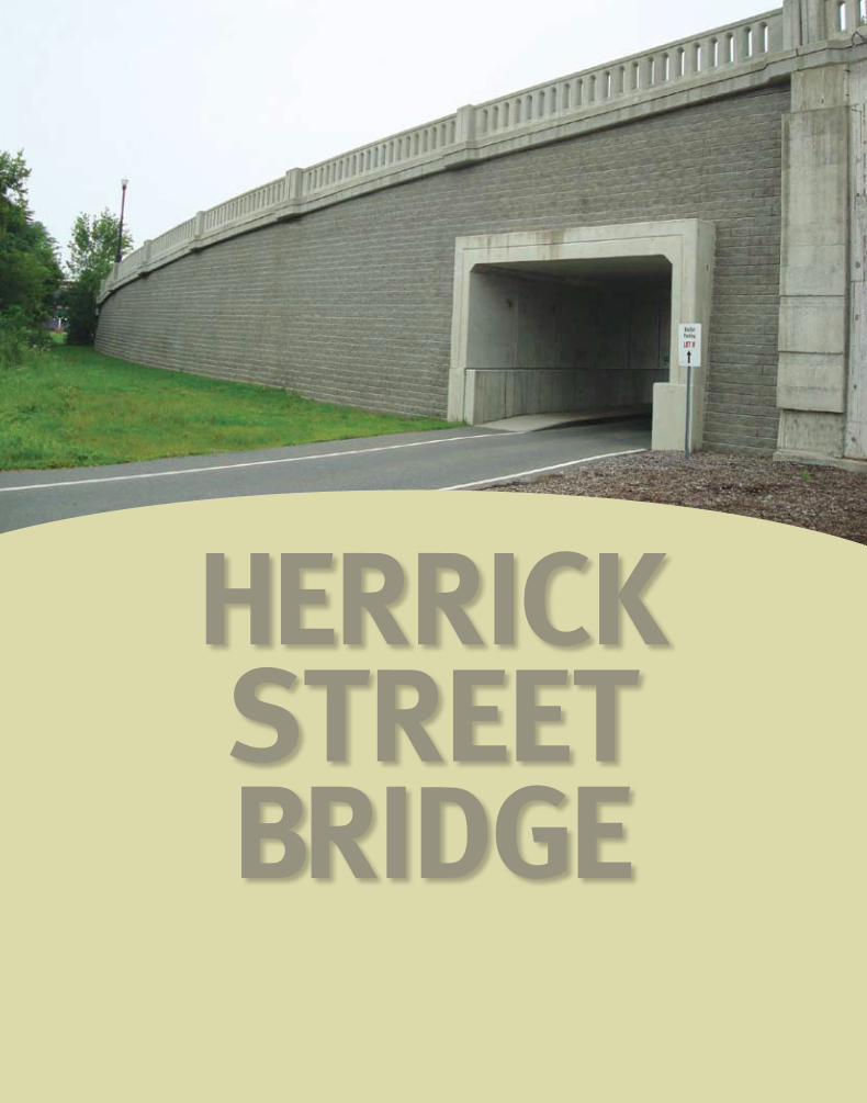
Herrick Street Bridge
concrete Masonry Designs I Hardscape Issue n 7
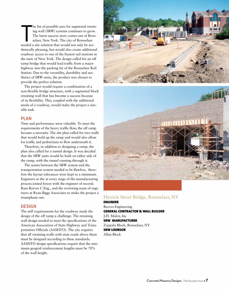
HerrickStreetBridge,Rensselaer,NYENGINEERReeves EngineeringGENERAL CONTRACTOR & WALL BUILDERJ.H. Maloy, IncSRW MANUFACTURERZappalaBlock,Rensselaer,NYSRW LISENSORAllanBlock
The list of possible uses for segmental retain-ing wall (SRW) systems continues to grow. The latest success story comes out of Rens-selaer,NewYork.ThecityofRensselaer
needed a site solution that would not only be aes-thetically pleasing, but would also create additional roadway access to one of the busiest rail stations in thestateofNewYork.Thedesigncalledforanofframp bridge that would lead traffic from a major highway into the parking lot of the Rensselaer Rail Station. Due to the versatility, durability and aes-thetics of SRW units, the product was chosen to provide the perfect solution.
The project would require a combination of a non-flexible bridge structure, with a segmental block retaining wall that has become a success because of its flexibility. This, coupled with the additional needs of a roadway, would make the project a size-able task.
PLANTime and performance were valuable. To meet the requirements of the heavy traffic flow, the off ramp became a necessity. The site plan called for two walls that would hold up the ramp and would also allow for traffic and pedestrians to flow underneath it.
Therefore, in addition to designing a ramp, the plan also called for a tunnel design. It was decided that the SRW units would be built on either side of the ramp, with the tunnel running through it.
The seams between the SRW system and the transportation system needed to be flawless, there-fore the layout tolerances were kept to a minimum. Engineers at the at every stage of the manufacturing process joined forces with the engineer of record; Russ Reeves C Eng., and the reviewing team of engi-neersatRyan-BiggsAssociatestomaketheprojectatriumphant one.
DESIGNThe stiff requirements for the roadway made the design of the off ramp a challenge. The retaining wall design needed to meet the specifications of the American Association of State Highway and Trans-portation Officials (AASHTO). The city requires that all retaining walls with state roads above them must be designed according to these standards. AASHTO design specifications require that the min-imum geogrid reinforcement lengths must be 70% of the wall height.

9/ 09 8
These length requirements are much longer than the typical retaining wall industry standards. The design of the walls also included seismic activity analysis.Rensselaer,NewYorkisgenerallynotcon-sidered a seismically active area; therefore seismic analysis would typically not be required.
BUILD TheconstructionoftheHerrickStreetBridgeneeded to be very well thought-out. The surveying team spent many hours laying out the placement of the walls and accounting for the block setback.
This was especially critical since the design required the walls on each side of the roadway to have 31 feet (9.45 m) of spacing between them at the top. During the placement of the units there were several things that needed to be considered. Since there were manholes and storm drains behind the wall, the geogrid reinforcement could not be laid in the soil in the typical fashion. AASHTO required that the geogrid be fastened to all the manholes and storm drains.
The geogrid also needed to be cut and placed around and behind the obstructions. In addition, the construction crew had to build around the tunnel that went through the retaining walls.
In constructing the wall, the top two courses of SRW units were grouted together, the top course of geogrid reinforcement extended from one wall to the other, and the cap blocks were added to keep the step downs less than six inches (15 cm).
A Texas barrier and sidewalks were also con-structed at the top of the retaining wall followed by paving the road. The cooperation and dedication of the many individuals involved in the project made theHerrickStreetBridgeasuccess.CMd
Images courtesy of Allan Block.

NCMA TEK 14-18B 1
A n i n f o r m a t i o n s e r i e s f r o m t h e n a t i o n a l a u t h o r i t y o n c o n c r e t e m a s o n r y t e c h n o l o g y
SEISMIC DESIGN AND DETAILINGREQUIREMENTS FORMASONRY STRUCTURES
TEK 14-18BStructural (2009)
INTRODUCTION
Historically, degree of seismic risk and the resulting design loads have been linked to seismic zones, with higher seismic zones associated with higher anticipated ground motion. More recently, design codes and standards (refs. 1, 2, 3) have replaced the use of seismic zones with Seismic Design Categories (SDCs). While seismic zones and design categories share similar concepts, there are also specifi c considerations that make each unique. The information that follows outlines the procedure for defi ning a project’s SDC, the permissible design methods that can be used with each SDC, and the prescriptive reinforcement associated with each SDC level. This TEK is based on the requirements of the 2006 and 2009 editions of the International Building Code (IBC) (refs. 3a, 3b). While the applicable seismic provisions covered have not changed signifi cantly over the last several code cycles, designers and contractors should be aware of several key revisions that have been introduced in recent years.
SEISMIC DESIGN CATEGORIES
SDCs range from SDC A (lowest seismic risk) through SDC F (highest seismic risk). Several factors contribute to defi ning the seismic design category for a particular project, including:• Maximum earthquake ground motion. Ground ac-celeration values are obtained from maps published in the IBC (ref. 3) or the ASCE 7 Minimum Design Loads for Buildings and Other Structures (ref. 2).• Local soil profi le. Soil profi les are classifi ed as Site Class A (hard rock) through Site Class F (organic or liq-uefi able soils). When the soil properties are not know in suffi cient detail to determine the site class, Site Class D (moderately stiff soil) is assumed.• Use or occupancy hazard of the structure. Each structure is assigned to one of four unique Occupancy Categories corresponding to its use or hazard to life safety. Structures assigned to Occupancy Category I include those
with a very low hazard to human life in the event of failure (including many agricultural buildings and minor storage facilities). Structures assigned to Occupancy Category III include those that would present a substantial public hazard including schools, jails, and structures with an occupancy load greater than 5,000. Structures assigned to Occupancy Category IV are designated essential facilities (such as hospitals and fi re stations) and structures that contain substantial quantities of hazardous materials. Structures assigned to Occupancy Category II are those not included in any of the other three categories. Figures 1 and 2 defi ne the SDC for 0.2 and 1 second spectral response acceleration, respectively. Each fi gure is based on Site Class D (the default class when the soil profi le is not known) and is applicable to structures assigned to Occupancy Categories I, II, and III (buildings other than high hazard exposure structures). Note that if the soil profi le is known and is lower than D, a correspondingly lower SDC may be realized. Structures are assigned to the highest SDC obtained from either Figure 1 or Figure 2. Alternatively, Section 1613.5.6.1 of the 2006 or 2009 IBC (refs. 3a, 3b) permits the SDC to be determined based solely on Figure 1 (0.2 second spectral response acceleration) for relatively short, squat structures (common for masonry buildings) meeting the requirements of that section. Table 1 may be used to apply Figures 1 and 2 to structures assigned to Occupancy Category IV.
DESIGN LIMITATIONS
Based on the assigned SDC, limitations are placed on the design methodology that is permitted to be used for the design of the seismic force-resisting system (i.e., the masonry shear walls). Designers have the option of using several design methods for masonry structures: empirical design (ref. 4); allowable stress design (ref. 5); strength design (ref. 6); or prestressed masonry design (ref. 7), each of which is based on the provisions contained in the Masonry Stan-dards Joint Committee Building Code Requirements for
Related TEK:14-4B, 14-7B, 14-8B, 14-12B, 14-20A
Keywords: earthquake, prescriptive reinforcement, nonloadbearing walls, rein-forced concrete masonry, seismic, seismic design category, shear walls, unreinforced concrete masonry

2 NCMA TEK 14-18B
Figure 1—Seismic Design Categories for Site Class D, Seismic Use Group I and II, for a 0.2-Second Spectral Response Acceleration
Figure 2—Seismic Design Categories for Site Class D, Seismic Use Group I and II, for a 1-Second Spectral Response Acceleration
A
A
B
B
A
B
A
B
Legend:
SDC A
SDC B
SDC C
SDC D
Legend: SDC C
SDC A SDC D
SDC B SDC E

2006 IBC SEISMIC DESIGN AND DETAILING REQUIREMENTS
The seismic design and detailing provisions for ma-sonry are invoked through Section 2106 of the IBC (ref. 3a), which in turn references the 2005 MSJC (ref. 1a). The IBC provisions detail a series of modifi cations and additions to the seismic requirements contained in the MSJC, which include:• IBC Section 2106.1 requires all masonry walls, regardless of SDC, not designed as part of the seismic force-resisting system (partition and nonloadbearing walls, eg.) to be struc-turally isolated, so that in-plane loads are not inadvertently imparted to them. The MSJC, conversely, requires isolation of such elements only for SDC C and higher.• IBC Section 2106.1.1 outlines minimum prescriptive detailing requirements for three prestressed masonry shear wall types: ordinary plain, intermediate, and spe-cial prestressed masonry shear walls. While the MSJC contains general design requirements for prestressed masonry systems, it does not contain prescriptive seismic requirements applicable to this design approach.• Anchorage requirements are addressed by Section 2106.2 of the IBC. Although analogous requirements are included in MSJC Section 1.14.3.3, the MSJC requirements are based on antiquated design loads that are no longer compatible with those of the IBC.• For structures assigned to SDC C and higher that include columns, pilasters and beams, and that are part of the seismic force-resisting system and support discontinuous masonry walls, IBC Section 2106.4.1 requires these elements to have a minimum transverse reinforcement ratio of 0.0015, with a maximum transverse reinforcement spacing of one-fourth the least nominal dimension for columns and pilasters and one-half the nominal depth for beams.• For structures assigned to SDC D and higher, IBC Section 2106.5 includes modifi cations that are an indirect means of attempting to increase the fl exural ductility of elements that are part of the seismic force-resisting system. For elements designed by allowable stress design provisions (MSJC Chapter 2), in-plane shear and diagonal tension stresses are required to be increased by 50 percent. For elements designed by strength design provisions (MSJC Chapter 3) that are controlled by fl exural limit states, the nominal shear strength at the base of a masonry shear wall is limited to the strength provided by the horizontal shear reinforcement in accordance with Eqn. 1.
Masonry Structures (MSJC) (ref. 1). There are, however, restrictions placed on the use of both empirical design and unreinforced masonry, neither of which considers reinforce-ment, if present, as contributing to the structure's strength or ductility. Table 2 summarizes the design procedures that may be used for each SDC. Similarly, as the seismic risk/hazard increases, codes require more reinforcement to be incorporated into the structure. This reinforcement is prescriptively required as a minimum and is not a function of any level of determined loading on the structure. That is, design loads may require a specifi c reinforcement schedule to safely resist applied loads, which cannot be less than the minimum prescriptive seismic reinforcement triggered by the assigned SDC. For convenience, each level of prescriptive seismic reinforce-ment is given a unique name as summarized in Table 3. The following discussion reviews in detail the seismic design requirements for loadbearing and nonloadbearing concrete masonry assemblies as required under the 2006 and 2009 IBC, which in turn reference the 2005 and 2008 MSJC, respectively. While many of the seismic design and detailing requirements between these two code edi-tions are similar, there are unique differences that need to be considered when using one set of provisions over the other. The information presented covers the seismic design and detailing requirements for all concrete masonry construction with the exception of concrete masonry ve-neers, which is addressed in TEK 3-6B, Concrete Masonry Veneers (ref. 8). The requirements listed below for each SDC and shear wall type are cumulative. That is, masonry assemblies in structures assigned to SDC B must meet the requirements for SDC A as well as those for SDC B. Buildings assigned to SDC C must meet the requirements for Categories A, B and C, and so on.
NCMA TEK 14-18B 3
Table 2—Permitted Design Procedures for Elements Participating in the Lateral Force-Resisting System
Empirical Allowable stress design Strength design Prestressed SDC design Unreinforced Reinforced Unreinforced Reinforced A X X X X X X B X X X X X C X X X D X X X E X X X F X X X
Table 1—SDC for Structures Assigned to Occupancy Category IV
SDC based on Revised SDC for Figures 1 and 2 Occupancy Category IV A A B C C D D D E F

Vn = An ρn fy Eqn. 1 Due to a shear capacity check in MSJC Section 3.1.3 that requires the nominal shear strength of a shear wall to equal or exceed the shear corresponding to the development of approximately 156% of the nominal fl exural strength, Equation 1 controls except in cases where the nominal shear strength equals or exceeds 250% of the required shear strength. For such cases, the nominal shear strength is determined as a combination of the shear strength provided by the masonry and the shear reinforcement.
2005 MSJC Seismic Design and Detailing Requirements The majority of the prescriptive seismic design and detailing requirements for masonry assemblies are invoked by reference to Section 1.14 of the 2005 MSJC. The fol-lowing summarizes these requirements as they apply to concrete masonry construction.
Masonry Shear Wall Types In addition to the prestressed masonry shear walls outlined by the IBC, the MSJC includes detailing require-ments for six different shear wall options. A summary of these shear wall types follows. Table 3 summarizes the SDCs where each shear wall type may be used.Empirically Designed Masonry Shear Walls—Masonryshear walls designed by the empirical design method (MSJC Chapter 5). Empirically designed masonry shear walls do not account for the contribution of reinforcement (if present) in determining the strength of the system.Ordinary Plain (Unreinforced) Masonry Shear Walls—Ordinary plain masonry shear walls are designed as unreinforced elements, and as such rely entirely on the masonry to carry and distribute the anticipated loads. These shear walls do not require any prescriptive reinforcement. As such, they are limited to SDCs A and B.Detailed Plain (Unreinforced) Masonry Shear Walls—Detailed plain masonry shear walls are also designed as unreinforced elements, however some prescriptive reinforcement is mandated by the MSJC to help ensure a minimum level of inelastic deformation capacity and energy dissipation in the event of an earthquake. As the anticipated seismic risk increases (which corresponds to higher SDCs), the amount of prescriptive reinforcement also increases. The minimum prescriptive reinforcement for detailed plain masonry shear walls is shown in Figure 3.Ordinary Reinforced Masonry Shear Walls—Ordinary
4 NCMA TEK 14-18B
reinforced masonry shear walls, which are designed using reinforced masonry procedures, rely on the reinforcement to carry and distribute anticipated tensile stresses, and on the masonry to carry compressive stresses. Although such walls contain some reinforcement, the MSJC also mandates prescriptive reinforcement to ensure a minimum level of performance during a design level earthquake. The reinforce-ment required by design may also serve as the prescriptive reinforcement. The minimum prescriptive vertical and hori-zontal reinforcement requirements are identical to those for detailed plain masonry shear walls (see Figure 3).Intermediate Reinforced Masonry Shear Walls—Interme-diate reinforced masonry shear walls are designed using reinforced masonry design procedures. Intermediate rein-forced shear wall reinforcement requirements differ from those for ordinary reinforced in that the maximum spacing of vertical reinforcement is reduced from 120 in. (3,048 mm) to 48 in. (1,219 mm) (see Figure 4).Special Reinforced Masonry Shear Walls—Prescriptivereinforcement for special reinforced masonry shear walls must comply with the requirements for intermediate rein-forced masonry shear walls and the following (see also Figure 5):• The sum of the cross-sectional area of horizontal and vertical reinforcement must be at least 0.002 times the gross cross-sectional wall area.• The cross-sectional reinforcement area in each direction must be at least 0.0007 times the gross cross-sectional wall area.• The vertical and horizontal reinforcement must be uni-formly distributed.• The minimum cross-sectional area of vertical rein-forcement must be one-third of the required horizontal reinforcement.• All horizontal reinforcement must be anchored around the vertical reinforcement with a standard hook. The following additional requirements pertain to stack bond masonry shear walls assigned to SDC D, E or F. These walls must be constructed using fully grouted open-end units, fully grouted hollow units laid with full head joints, or solid units. The maximum reinforcement spacing for stack bond masonry shear walls assigned to SDC D is 24 in. (610 mm). For those assigned to SDC E or F, the cross-sectional area of horizontal reinforcement must be at least 0.0025 times the gross cross-sectional area of the masonry, and it must be spaced at 16 in. (406 mm) o.c., maximum.
Table 3—Permitted Shear Wall Types for Seismic Design Categories
Ordinary Detailed Ordinary Intermediate Special SDC Empirical unreinforcedA unreinforced reinforced reinforcedA reinforcedA
A X X X X X X B X X X X X C X X X D X E X F X
A Includes prestressed masonry assemblies meeting the same prescriptive reinforcement requirements as conventional masonry construction.

NCMA TEK 14-18B 5
Prescriptive Seismic Detailing for Nonloadbearing Elements When incorporated into structures assigned to SDC C, D, E or F, masonry partition walls and other nonloadbear-ing masonry elements (i.e., those not designed to resist loads other than those induced by their own mass) must be isolated from the lateral force-resisting system. This helps ensure that forces are not inadvertently transferred from the structural to the nonstructural system. Nonstruc-tural elements, such as partition walls, assigned to SDC C and above must be reinforced in either the horizontal or vertical direction (see Figure 6).
2009 IBC SEISMIC DESIGN AND DETAILING REQUIREMENTS
Unlike the 2006 IBC, the 2009 edition, which refer-ences the 2008 MSJC, contains no modifi cations to the seismic design and detailing provisions of the referenced standard. A summary of the substantive differences be-tween the seismic design and detailing provisions of the 2005 and 2008 editions of the MSJC follows.
2008 MSJC Seismic Design and Detailing Requirements
The 2008 MSJC includes a comprehensive reorga-nization of the seismic design and detailing requirements intended to clarify the scope and intent of these provisions. In addition to the reorganization, several substantive changes applicable to concrete masonry construction have been incorporated, and these are detailed below. The prescriptive seismic detailing requirements for masonry shear walls remains substantially the same as under the 2005 MSJC and 2006 IBC.Participating versus Nonparticipating Members—Ele-ments of a masonry structure must now be explicitly clas-sifi ed either as participating in the seismic force-resisting system (for example, shear walls) or as nonparticipating members (for example, nonloadbearing partition walls). Elements designated as shear walls must satisfy the requirements for one of the designated shear wall types. Nonparticipating members must be appropriately isolated to prevent their inadvertent structural participation. This provision is similar in intent to the 2006 IBC requirement to isolate partition walls in SDC A and higher.Connections—In previous editions of the MSJC, a minimum unfactored (service level) connection design force of 200 lb/ft (2,919 N/m) was prescribed for all masonry shear wall assemblies except ordinary plain (unreinforced) masonry shear walls. In the 2008 MSJC, this minimum design load has been removed and replaced with a reference to the minimum loads prescribed by the adopted model building code. When the adopted model building code does not prescribe such loads, the requirements of ASCE 7 are to be used, which require a factored design force (strength level) of 280 lb/ft (4,087 N/m).Story Drift—Due to the inherent stiffness of masonry structures, designers are no longer required to check the displacement of one story relative to adjacent stories for
most masonry systems, simplifying the design process. Shear wall systems that are not exempted from checks for story drift include prestressed masonry shear walls and special reinforced masonry shear walls.Stack Bond Prescriptive Detailing—Special reinforced masonry shear walls constructed of masonry laid in stack bond must now have a minimum area of horizontal reinforce-ment of 0.0015 times the gross cross-sectional wall area. This is an increase from the 0.0007 required in such walls in structures assigned to SDC D, and is a decrease from the 0.0025 required in such walls in structures assigned to SDC E and F by earlier editions of the MSJC.Shear Capacity Check—In the 2005 MSJC, all masonry elements (both reinforced and unreinforced) designed by the strength design method were required to have a design shear strength exceeding the shear correspond-ing to the development of 125 percent of the nominal fl exural strength, but need not be greater than 2.5 times the required shear strength. Because this provision is related primarily to the seismic performance of masonry structures, the 2008 MSJC requires it only for special re-inforced masonry shear walls. Similarly, when designing special reinforced masonry shear walls by the allowable stress design method, the shear and diagonal tension stresses resulting from in-plane seismic forces are required to be increased by a factor of 1.5. Each of these checks is intended to increase fl exural ductility while decreasing the potential for brittle shear failure.Stiffness Distribution—In Chapter 1 of the 2008 MSJC, prescriptive seismic detailing requirements for masonry shear walls are related to an implicit level of inelastic ductile capacity. Because these detailing provisions apply primarily to shear walls, which in turn provide the principal lateral force-resistance mechanism for earthquake loads, the 2008 MSJC requires that the seismic lateral force-resisting system consist mainly of shear wall elements. At each story, and along each line of lateral resistance within a story, at least 80 percent of the lateral stiffness is required to be provided by shear walls. This require-ment is intended to ensure that other elements, such as masonry piers and columns, do not contribute a signifi cant amount of lateral stiffness to the system, which might in turn inadvertently change the seismic load distribution from that assumed in design. The 2008 MSJC does permit, however, the unlimited use of non-shear wall elements such as piers and columns provided that design seismic loads are determined using a seismic response modifi cation factor, R, of 1.5 or less, consistent with the assumption of essentially elastic response to the design earthquake. In previous editions of the MSJC, these requirements were imposed only for masonry designed by the strength design method. In the 2008 MSJC, this requirement applies to all structures assigned to SDC C or higher.Support of Discontinuous Elements—New to the 2008 MSJC, which was previously found in the 2006 IBC provisions, are the prescriptive detailing requirements for masonry columns, pilasters, and beams supporting discontinuous stiff elements that are part of the seismic force-resisting system. Such elements can impose actions from gravity loads, and also from seismic overturning, and
Vn = An ρn fy Eqn. 1 Due to a shear capacity check in MSJC Section 3.1.3 that requires the nominal shear strength of a shear wall to equal or exceed the shear corresponding to the development of approximately 156% of the nominal fl exural strength, Equation 1 controls except in cases where the nominal shear strength equals or exceeds 250% of the required shear strength. For such cases, the nominal shear strength is determined as a combination of the shear strength provided by the masonry and the shear reinforcement.
2005 MSJC Seismic Design and Detailing Requirements The majority of the prescriptive seismic design and detailing requirements for masonry assemblies are invoked by reference to Section 1.14 of the 2005 MSJC. The fol-lowing summarizes these requirements as they apply to concrete masonry construction.
Masonry Shear Wall Types In addition to the prestressed masonry shear walls outlined by the IBC, the MSJC includes detailing require-ments for six different shear wall options. A summary of these shear wall types follows. Table 3 summarizes the SDCs where each shear wall type may be used.Empirically Designed Masonry Shear Walls—Masonryshear walls designed by the empirical design method (MSJC Chapter 5). Empirically designed masonry shear walls do not account for the contribution of reinforcement (if present) in determining the strength of the system.Ordinary Plain (Unreinforced) Masonry Shear Walls—Ordinary plain masonry shear walls are designed as unreinforced elements, and as such rely entirely on the masonry to carry and distribute the anticipated loads. These shear walls do not require any prescriptive reinforcement. As such, they are limited to SDCs A and B.Detailed Plain (Unreinforced) Masonry Shear Walls—Detailed plain masonry shear walls are also designed as unreinforced elements, however some prescriptive reinforcement is mandated by the MSJC to help ensure a minimum level of inelastic deformation capacity and energy dissipation in the event of an earthquake. As the anticipated seismic risk increases (which corresponds to higher SDCs), the amount of prescriptive reinforcement also increases. The minimum prescriptive reinforcement for detailed plain masonry shear walls is shown in Figure 3.Ordinary Reinforced Masonry Shear Walls—Ordinary
4 NCMA TEK 14-18B
reinforced masonry shear walls, which are designed using reinforced masonry procedures, rely on the reinforcement to carry and distribute anticipated tensile stresses, and on the masonry to carry compressive stresses. Although such walls contain some reinforcement, the MSJC also mandates prescriptive reinforcement to ensure a minimum level of performance during a design level earthquake. The reinforce-ment required by design may also serve as the prescriptive reinforcement. The minimum prescriptive vertical and hori-zontal reinforcement requirements are identical to those for detailed plain masonry shear walls (see Figure 3).Intermediate Reinforced Masonry Shear Walls—Interme-diate reinforced masonry shear walls are designed using reinforced masonry design procedures. Intermediate rein-forced shear wall reinforcement requirements differ from those for ordinary reinforced in that the maximum spacing of vertical reinforcement is reduced from 120 in. (3,048 mm) to 48 in. (1,219 mm) (see Figure 4).Special Reinforced Masonry Shear Walls—Prescriptivereinforcement for special reinforced masonry shear walls must comply with the requirements for intermediate rein-forced masonry shear walls and the following (see also Figure 5):• The sum of the cross-sectional area of horizontal and vertical reinforcement must be at least 0.002 times the gross cross-sectional wall area.• The cross-sectional reinforcement area in each direction must be at least 0.0007 times the gross cross-sectional wall area.• The vertical and horizontal reinforcement must be uni-formly distributed.• The minimum cross-sectional area of vertical rein-forcement must be one-third of the required horizontal reinforcement.• All horizontal reinforcement must be anchored around the vertical reinforcement with a standard hook. The following additional requirements pertain to stack bond masonry shear walls assigned to SDC D, E or F. These walls must be constructed using fully grouted open-end units, fully grouted hollow units laid with full head joints, or solid units. The maximum reinforcement spacing for stack bond masonry shear walls assigned to SDC D is 24 in. (610 mm). For those assigned to SDC E or F, the cross-sectional area of horizontal reinforcement must be at least 0.0025 times the gross cross-sectional area of the masonry, and it must be spaced at 16 in. (406 mm) o.c., maximum.
Table 3—Permitted Shear Wall Types for Seismic Design Categories
Ordinary Detailed Ordinary Intermediate Special SDC Empirical unreinforcedA unreinforced reinforced reinforcedA reinforcedA
A X X X X X X B X X X X X C X X X D X E X F X
A Includes prestressed masonry assemblies meeting the same prescriptive reinforcement requirements as conventional masonry construction.

6 NCMA TEK 14-18B
*In lieu of bond beams with No. 4 bars (M #13) at 120 in. (3,048 mm) on center, provide two wires of wire size W1.7(MW 11) joint reinforcement at 16 in. (406 mm) on center.
8 in. (203 mm)maximum
120 in.(3,048 mm)maximum*
16 in.(406 mm)maximum
16 in. (406 mm)maximum
Continue horizontal reinforcementthrough control joint as required
at diaphragms
Reinforcementwithin 16 in. (406 mm)of openings largerthan 16 in. (406 mm)
8 in.(203 mm)maximum
Controljoint
MinimumNo. 4
(M #13)prescriptive
reinforcement
24 in.(610 mm)or 40d
48 in.(1,219 mm)maximum
b
Figure 3—Prescriptive Seismic Detailing for Detailed Plain (Unreinforced) Masonry Shear Walls and for Ordinary Reinforced Masonry Shear Walls
Figure 4—Prescriptive Seismic Detailing for Intermediate Reinforced Masonry Shear Walls
*In lieu of bond beams with No. 4 bars (M #13) at 120 in. (3,048 mm) on center, provide two wires of wire size W1.7(MW 11) joint reinforcement at 16 in. (406 mm) on center.
16 in. (406 mm)maximum
8 in. (203 mm)maximum
120 in.(3,048 mm)maximum*
16 in.(406 mm)maximum
Continue horizontal reinforcementthrough control joint asrequired at diaphragms
Controljoint
8 in.(203 mm)maximum
MinimumNo. 4 (M #13)prescriptive
reinforcement
Reinforcementwithin 16 in. (406 mm)of openings largerthan 16 in. (406 mm)
120 in. (3,048 mm)maximum
24 in. (610 mm)or 40db

NCMA TEK 14-18B 7
Figure 5—Prescriptive Seismic Detailing for Special Reinforced Masonry Shear Walls
Figure 6—Reinforcement Options for Nonloadbearing Elements in SDC C and Higher
8 in. (203 mm)maximum
16 in. (406 mm)maximum
16 in.(406 mm)maximum
MinimumNo. 4 (M #13)prescriptivereinforcement
Reinforcementwithin 16 in. (406 mm)of openings largerthan 16 in. (406 mm)
Maximum13 height
13 length, or 48 in.
(1,219 mm)
16 in.(406 mm)maximum
*Note: For stack bond construction of masonry partition walls in Seismic Design Category E or F, the maximum spacing of horizontal reinforcement is 24 inches (610 mm). The horizontal cross-sectional area of reinforcement is required to be at least 0.0015 times the gross cross-sectional area of the masonry. Stack bond partition walls are also required to be constructed of solidly grouted hollow open-end units or two wythes of solid units.
Isolationjoint
Isolationjoint
Isolationjoint
As an alternative to bond beams, bed joint reinforcement may be incorporated at a maximum spacing of 16 in. (406 mm)
16 in. (406 mm)maximum
48 in. (1,219 mm)maximum*
16 in. (406 mm)maximum
48 in.(1,219 mm)maximum
Isolationjoint
16 in. (406 mm)maximum
**Joint reinforcement alternative to bond beams: For walls thicker than 4 in. (102 mm), two longitudi-nal W1.7 (MW 11) wires minimum. For walls 4 in. (102 mm) thick or less, only one W1.7 (MW 11) wire is required. The maximum joint reinforcement spacing is 16 in. (406 mm) for either case.
Bond beams with one No. 4 (M#13) minimum**
Isolation joint
Horizontal Reinforcement Option
Vertical Reinforcement Option
l
.
Isolationjoint
16 in. (406 mm)maximum
48 in.(1,219 mm)maximum
Isolationjoint
No. 4 (M#13), minimum (typ.)

9/ 09 16
8 NCMA TEK 14-18B
REFERENCES1. Building Code Requirements for Masonry Structures, Reported by the Masonry Standards Joint Committee. a. 2005 Edition: ACI 530-05/ASCE 5-05/TMS 402-05 b. 2008 Edition: TMS 402-08/ACI 530-08/ASCE 5-082. Minimum Design Loads for Buildings and Other Structures, ASCE 7-05. American Society of Civil Engineers, 2005.3. International Building Code. International Code Council. a. 2006 Edition b. 2009 Edition4. Empirical Design of Concrete Masonry Walls, TEK 14-8B. National Concrete Masonry Association, 2008.5. Allowable Stress Design of Concrete Masonry, TEK 14-7B. National Concrete Masonry Association, 2009.6. Strength Design of Concrete Masonry, TEK 14-4B. National Concrete Masonry Association, 2008.7. Post-Tensioned Concrete Masonry Wall Design, TEK 14-20A. National Concrete Masonry Association, 2002.8. Concrete Masonry Veneers, TEK 3-6B. National Concrete Masonry Association, 2005.
NCMA and the companies disseminating this technical information disclaim any and all responsibility and liability for the accuracy and the application of the information contained in this publication.
NATIONAL CONCRETE MASONRY ASSOCIATION13750 Sunrise Valley Drive, Herndon, Virginia 20171
www.ncma.org
To order a complete TEK Manual or TEK Index, contact NCMA Publications (703) 713-1900
Table 4—Seismic Design Coeffi cients and Factors for Masonry Bearing Wall Systems
Response modifi cation Systems overstrength Defl ection amplifi cationShear wall type: coeffi cient, R factor, Ω0 factor, Cd
Empirical Not applicable Not applicable Not applicableOrdinary plain (unreinforced) 1.5 2.5 1.25Detailed plain (unreinforced) 2 2.5 1.75Ordinary reinforced 2 2.5 1.75Intermediate reinforced 3.5 2.5 2.25Special reinforced 5 2.5 3.5Prestressed 1.5 2.5 1.75
therefore require that the columns, pilasters and beams supporting them have stricter prescriptive reinforcement requirements. These requirements apply only to structures assigned to SDC C and higher.System Response Factors for Prestressed Masonry—Indetermining seismic base shear and story drift for structures whose seismic lateral force-resisting system consists of prestressed masonry shear walls, the value of the re-
sponse modifi cation coeffi cient, R, and of the defl ection amplifi cation factor, Cd, are required to be taken equal to those used for ordinary plain (unreinforced) masonry shear walls. The requirement previously existed as a recommendation in the MSJC Code Commentary. These values, as they apply to all types of masonry shear walls, are summarized in Table 4.

• Saves over half the labor & materials of thru-wall membrane flashing in a multi-wythe course, while delivering up to 10 times stronger bond and eliminating the need for multiple sizes of Architectural CMU. • Works with 8˝, 10˝, and 12˝ exterior CMU. • Installs easily in reinforced walls. • NEW Drainage Matte eliminates the need for pea gravel. • Lightweight & compact for easy shipping, handling, and storage. • 40% recycled polypropylene can help your project qualify for LEED certification.
Drop Blok-Flash® pans onto each 1st course block, with
Weep Spouts protruding.
Grout according to instructions, then lay 2nd course.
Press a lightweight, polyester-meshDrainage Matte into each cavity of 2nd course block to capture mortar/
grout droppings. (No pea gravel.)
With NEW Blok-Flash®, it’s easier than ever to protect your CMU exterior walls against moisture damage & mold growth... while
protecting yourself against the high costs ofinstalling other moisture control systems!
Stronger than flashing, and it installs in a flash.
21 3

9/ 09 18
Fences, Railings, and Traffic Barriers
Often fences, stair rails, guide rails, or concrete traffic barriers are needed behind a segmental retaining wall (SRW). With proper design and installation, a variety of structural and aesthetic features can be placed at the top of a SRW wall.

concrete Masonry Designs I Hardscape Issue n 19
FENCESWhen there is sufficient space, the easiest and most cost-effective way to install fences above SRW walls is to place them several feet (0.5–1 m) behind walls. With sufficient fence post depth and setback, the soil can provide a stable foundation. Separating fence posts from a wall also keeps wall movement from affecting the fence. While a minimum post depth of 30 inches (760 mm) is suggested, the embedment and distance behind the wall needed to create a stable post founda-tion varies and depends on the soil conditions. One option is to create post holes during wall construction by placing cylindrical tube forms at planned post loca-tions and backfilling soil around them. After complet-ing the wall, the tubes are filled with concrete and the fence posts set in the concrete (Figure 1).
When there is not enough room to set fence posts behind walls, they can be installed within top wall units priortobackfillingbehindthewall.Breakoffthebacksof the top few units to create room for the post. Cut or core the cap units to neatly receive posts (Figures 2 and 3). The fence should be flexible enough to accommo-date differential movement between the units and the fence.
Placing posts near the front of a wall decreases the fence’s foundation support. To improve stability to the post, the concrete foundation should be enlarged, extended behind the wall and reinforced with reinforc-ing steel (Figures 2 and 3). The needed depth, extension length and reinforcement placement will vary depend-ing on conditions and loading.
GUARD RAILSWith proper design, guard rails can be used behind SRW walls. For proper support, place guard rails sev-eral feet (m) behind the wall units (Figure 4). The set-back and embedment depth of the guard rail will vary with conditions and loading. For highway loading, American Association of State Highway and Transpor-tation Officials (AASHTO recommends an embedment depth of 5 feet (1.5 m). Like fence posts, guard rails can be placed in cylindrical concrete tube forms placed during wall backfill.
POSTS PENETRATING GEOGRIDFor walls requiring soil reinforcement, fence and guide rail posts will often extend below the top layer or two of geogrid. Often the geogrid can be cut to fit around the planned post locations. Usually the top layers of geogrid can accommodate small intrusions while still maintaining overall tensile strength. However, the area cut from the geogrid should be no more than the mini-mum needed to fit the post. The wall design engineer
FIG
URE
1FI
GU
RE 2
FIG
URE
3FI
GU
RE 4

9/ 09 20
must evaluate any planned post intrusions into geogrid layers to ensure they do not reduce strengths below needed minimums. Augering or driving through back-filled geogrid after wall construction is generally not suggested because it may excessively disturb or pull geogrid from the soil or the wall units.
CONCRETE TRAFFIC BARRIERSWhen there is no room to set guide rails behind a wall, traffic barriers can be placed directly on top of a wall. These can be cast-in-place concrete or precast barri-ers (such as Jersey barriers) or a combination of both. Concrete barriers should be designed for stability, inde-pendent of the wall. The foundation can be extended behind the wall (moment slab) to act as cantilevered resistance to lateral and overturning loads (Figure 5).
A qualified engineer must design traffic barriers on a project-specific basis. Reinforcing steel, barrier size, and geometry will vary with site conditions and load-ing. Other design considerations include the need for control joints, expansion joints and bond breaks to address differential movement between the barrier and the retaining wall. During concrete placement for cast-inplace barriers, temporary bracing of the retaining wall may also be required.
STAIR RAILSSRW stairs can accommodate a variety of railings with proper design, including railings anchored just above and below steps, into side wall units, or into step risers. Solid SRW units allow use of several common techniques for attaching railings to concrete, including fasteners that embed in polymer, grout or mortar, or anchors that cut threads into the concrete. The appro-priate fastener varies with loading and site conditions. Refer to the fastener manufacturer’s and wall design engineer’s recommendations.
When practical, spanning railings from landing to landing and placing posts directly into the soil is usu-ally the easiest way to provide a stable foundation for stair railings. When stairs have numerous risers and spanning is not practical, railings can be attached to the units in the side walls. When there are no side walls, rail posts can be placed through the step units (Figure 6). Step units can be split or cut to extend post hole at least 30 inches (760 mm) deep (more depth may be needed depending on loading). The post hole should be filled with concrete.
Caps can be cored to receive the post neatly, if desired.
FIG
URE
5FI
GU
RE 6
FIG
URE
7
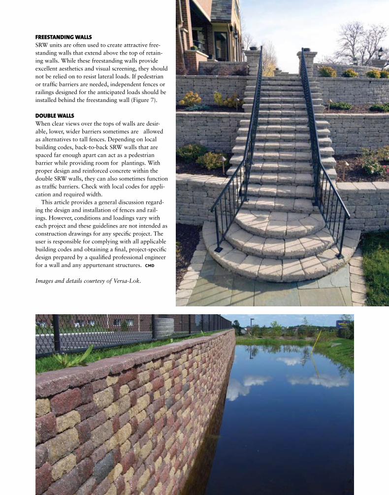
FREESTANDING WALLSSRW units are often used to create attractive free-standing walls that extend above the top of retain-ing walls. While these freestanding walls provide excellent aesthetics and visual screening, they should not be relied on to resist lateral loads. If pedestrian or traffic barriers are needed, independent fences or railings designed for the anticipated loads should be installed behind the freestanding wall (Figure 7).
DOUBLE WALLSWhen clear views over the tops of walls are desir-able, lower, wider barriers sometimes are allowed as alternatives to tall fences. Depending on local building codes, back-to-back SRW walls that are spaced far enough apart can act as a pedestrian barrier while providing room for plantings. With proper design and reinforced concrete within the double SRW walls, they can also sometimes function as traffic barriers. Check with local codes for appli-cation and required width.
This article provides a general discussion regard-ing the design and installation of fences and rail-ings. However, conditions and loadings vary with each project and these guidelines are not intended as construction drawings for any specific project. The user is responsible for complying with all applicable building codes and obtaining a final, project-specific design prepared by a qualified professional engineer for a wall and any appurtenant structures. CMd
Images and details courtesy of Versa-Lok.

9/ 09 22
d E T A I L o F T H E M o N T H
Reinforcement of Curved Walls
tial changes in length and elevations must be accounted for in plan and field construction layout of the wall to assure the minimum radius is not encroached upon and that project requirements are met.
For reinforced soil walls, specific details on place-ment of geosynthetic reinforcement at wall corners should be provided in the construction drawings.
Note that reinforcement is not overlapped in the same joint and that a minimum of 3 inches (76 mm) of soil is required between overlapping reinforcement.
The layout of curves and corners for SRWs requires planning by both the design engineer and contractor. The varying horizontal setback per course (Δu) among different types of SRW units must be considered prior to construction. This variable will dictate actual layout in plan and elevation. Leveling pad location will step up and back as elevation increases due to the horizontal set-back per course (Δu). The setback and inclination angles also create larger or smaller radii (lengths of curved wall) as the SRW increases in height, depending upon either a concave or convex orientation. These poten-
Typical Reinforcement Placement for Convex Corners
Notes:Alternate placement of reinforcement extension on specified reinforcement elevations.
Prin
cipl
e re
info
rcem
ent
dire
ctio
n
H/4
Alternate reinforcement H/4 extension on subsequent specified reinforcement elevationsSpecified reinforcement elevation
H/4 extensionbeyond wall
Principle reinforcement
direction
L
Squaredcorner
To complete placement of reinforcement for a specified placement elevation, place additional reinforcement on next course of segmental units immediately above the specified placement elevation, in a manner that eliminates gaps left by previous layer of geosynthetic at specified reinforcement elevation. If reinforcement placement is specified for successive lifts, ensure gaps in reinforcement are covered with reinforcement prior to backfilling
Prin
cipl
e re
info
rcem
ent
dire
ctio
n
Serpentine curves and 90° radius
corner
R
Specified reinforcement elevation
L
L
L
3 in. (76 mm) of soil required between overlappling reinforcement for proper anchorage if both layers placed at the same SRW unit elevation.
Alternative to overlapping in a single course, reinforcement could be placed in the perpendicular principle direction in the cross-over area on the succeeding course.
Principlereinforcement
directionL
Specified reinforcement
elevation
Prin
cipl
ere
info
rcem
ent
dire
ctio
n
Squared Corner
Principlereinforcement
directionPr
inci
ple
rein
forc
emen
tdi
rect
ion
3 in. (76 mm) of soil fill required between overlappling reinforcement for proper anchorage
Specified reinforcement
elevation
Curved cornerSerpentine
curvesand
90° radius corner
L
L
Typical Reinforcement Placement for Concave Corners
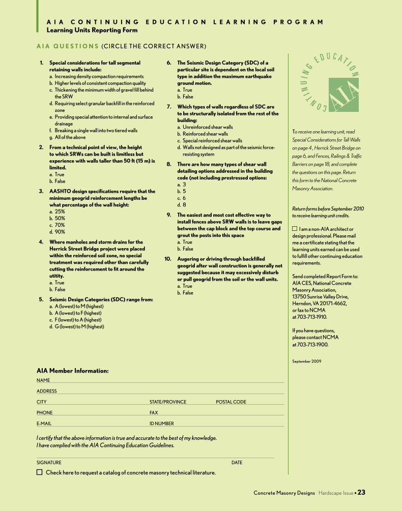
to receive one learning unit, read
Special Considerations for Tall Walls
on page 4 , Herrick Street Bridge on
page 6, and Fences, Railings & Traffic
Barriers on page 18, and complete
the questions on this page. Return
this form to the National Concrete
Masonry Association.
Return forms before September 2010 to receive learning unit credits.
i am a non-AiA architect or design professional. Please mail me a certificate stating that the learning units earned can be used to fulfill other continuing education requirements.
send completed Report form to: AiA ces, national concrete Masonry Association, 13750 sunrise Valley Drive, herndon, VA 20171-4662, or fax to ncMA at 703-713-1910. if you have questions, please contact ncMA at 703-713-1900.
september 2009
check here to request a catalog of concrete masonry technical literature.
AIA Member Information:nAMe
ADDRess
city stAte/PRoVince PostAl coDe
Phone fAx
e-MAil iD nuMbeR
I certify that the above information is true and accurate to the best of my knowledge. I have complied with the AIA Continuing Education Guidelines.
signAtuRe DAte
A I A C o N T I N u I N g E d u C A T I o N L E A r N I N g P r o g r A MLearning units reporting Form
concrete Masonry Designs I Hardscape Issue n 23
1. special considerations for tall segmental retaining walls include:a. increasing density compaction requirementsb. higher levels of consistent compaction qualityc. thickening the minimum width of gravel fill behind
the sRw d. Requiring select granular backfill in the reinforced
zonee. Providing special attention to internal and surface
drainagef. breaking a single wall into two tiered wallsg. All of the above
2. From a technical point of view, the height to which srWs can be built is limitless but experience with walls taller than 50 ft (15 m) is limited.a. trueb. false
3. AAsHTo design specifications require that the minimum geogrid reinforcement lengths be what percentage of the wall height:a. 25%b. 50%c. 70%d. 90%
4. Where manholes and storm drains for the Herrick street Bridge project were placed within the reinforced soil zone, no special treatment was required other than carefully cutting the reinforcement to fit around the utitity.a. trueb. false
5. seismic design Categories (sdC) range from:a. A (lowest) to M (highest)b. A (lowest) to f (highest)c. f (lowest) to A (highest)d. g (lowest) to M (highest)
6. The seismic design Category (sdC) of a particular site is dependent on the local soil type in addition the maximum earthquake ground motion.a. trueb. false
7. Which types of walls regardless of sdC are to be structurally isolated from the rest of the building: a. unreinforced shear wallsb. Reinforced shear wallsc. special reinforced shear wallsd. walls not designed as part of the seismic force-
resisting system
8. There are how many types of shear wall detailing options addressed in the building code (not including prestressed options:a. 3b. 5c. 6d. 8
9. The easiest and most cost effective way to install fences above srW walls is to leave gaps between the cap block and the top course and grout the posts into this spacea. trueb. false
10. Augering or driving through backfilled geogrid after wall construction is generally not suggested because it may excessively disturb or pull geogrid from the soil or the wall units.a. trueb. false
A I A Q u E s T I o N s ( c i R c l e t h e co R R e c t A n sw e R )

MasonryD e s i g n s
ConcreteMasonry
h a r d s c a p e i s s u e I September 2009
13750 Sunrise Valley DriveHerndon, VA 20171- 4662
A PublicAtion of the
www.ncMA.oRg
© 2008 Kiltie Corporation • Oakdale, MN
Mosaic Random Face Patterns
Freestanding Walls
Fully Integrated Stairs
Random-Pattern Tall Walls
Freestanding Columns
Multi-Angle Corners