concrete surfaced airfields - federal aviation · pdf file · 2014-05-23index of...
TRANSCRIPT
CONCRETE SURFACED AIRFIELDS
PAVER™ DISTRESS IDENTIFICATION MANUAL
DEVELOPED BY:
US ARMY CORPS OF ENGINEERS ERDC-CERL
SPONSORED BY:

FOREWORDFunding for this project was provided by the U.S. Air Force Civil Engineering Support Agency (AFCESA/ CESC), Tyndall Air Force Base, Florida.
This manual contains definitions and measuring methods for determining the Pavement Condition Index of Concrete Surfaced Airfields. This UFC implements STANAG 7181 ED 1 RD 1, Standard Method For Airfield Pavement Condition Index (PCI) Surveys.
This manual was prepared by Dr. M. Y. Shahin, U. S. Army Engineering Research and Development Center- Construction Engineering Research Laboratory, Champaign, IL.
June 2009
REFERENCES Kohn S.D. and Shahin, M.Y. (1984). Evaluation of the Pavement Condition Index for Use on Porous Friction Surfaces. Technical Report No. M-351, U.S. Army Construction Engineering Research Laboratory, Champaign, IL.
Shahin, M.Y., Darter, M.I., and Kohn, S.D. (1976-1977) Development of a Pavement Maintenance Management System, Vol. I-V. U.S. Air Force Engineering Services Center (AFESC), Tyndall AFB.

TABLE OF CONTENTS
Foreword ........................................................ 2
References .................................................... 2
Objective And Scope Of This Manual ...... 4
Frequently Occurring Problems In Pavement Distress ID .................................. 5
Distress Definitions ..................................... 6
Blowup (61)* ............................................... 6Corner Break (62) ....................................... 8Cracks (63) ............................................... 10Durability (“D”) Cracking (64) .................... 14Joint Seal Damage (65) ............................ 16Patching, Small (66) .................................. 18Patching, Large (67) ................................. 20Popouts (68) ............................................. 22Pumping (69) ............................................ 24Scaling (70) ............................................... 26Settlement Or Faulting (71) ....................... 28Shattered Slab (72) ................................... 30Shrinkage Cracks (73) .............................. 32Spalling (Joint) (74) ................................... 34Spalling (Corner) (75) ............................... 36Alkali Silica Reaction (76) ......................... 38

4
OBJECTIVE AND SCOPE OF THIS MANUALThis Manual contains distress definitions and measuring methods for concrete surfaced airfields. This information is used to determine the Pavement Condition Index (PCI).

5
FREQUENTLY OCCURRING PROBLEMS IN PAVEMENT DISTRESS IDENTIFICATION
Situation Action Remarks
1. Low severity scaling (i.e., crazing)
Count only if possible future scaling will occur within 2 to 3 years
2. Joint seal damageThis is not counted on a slab-by-slab basis
A severity level based on the overall condition of the joint seal in the sample unit is assigned
3. Joint spall small enough to be filled during a joint seal repair
Do not record
4. Medium or high severity intersecting crack (shattered slab)
No other distress should be counted
5. Corner or joint spalling caused by “D” cracking
Only “D” cracking should be recorded
If spalls are caused by factors other than “D” cracking, record each factor separately
6. Crack repaired by a narrow patch (e.g. 100 to 250 millimeters wide)
Record only crack and not patch at appropriate severity level
7. Original distress of patch more severe than patch itself
Original distress type should be recorded
If, for example, patch material present on scaled area of slab, only the scaling is counted
8. Hairline cracks that are only a few feet long and that do not extend across the entire slab
Should be rated as shrinkage cracks

6
BLOWUP (61)*
DescriptionBlowups occur in hot weather, usually at a transverse crack or joint that is not wide enough to permit expansion by the concrete slabs. The insufficient width is usually caused by infiltration of incompressible materials into the joint space. When expansion cannot relieve enough pressure, a localized upward movement of the slab edges (buckling) or shattering will occur in the vicinity of the joint. Blowups can also occur at utility cuts and drainage inlets. This type of distress is almost always repaired immediately because of severe damage potential to aircraft. Blowups are included for reference when closed sections are being evaluated for reopening.
Severity Levels
L Buckling or shattering has not rendered the pavement inoperative, and only a slight amount of roughness exists.
M Buckling or shattering has not rendered the pavement inoperative, but a significant amount of roughness exists.
H Buckling or shattering has rendered the pavement inoperative.
(Note: For pavements to be considered operational, all foreign material from blowups must have been removed.)
How To Count A blowup usually occurs at a transverse crack or joint. At a crack, it is counted as being in one slab, but at a joint, two slabs are affected and the distress should be recorded as occurring in two slabs.
*PAVER™ Distress Code

7
61 B
LOW
UP
L O
WM
E D
I U
MH
I G
H

8
CORNER BREAK (62)
DescriptionA corner break is a crack that intersects the joints at a distance less than or equal to one-half the slab length on both sides, measured from the corner of the slab. For example, a slab with dimensions of 25 by 25 feet (7 1/2 by 7 1/2 meters) that has a crack intersecting the joint 5 feet (1 1/2 meters) from the corner on one side and 17 feet (5 meters) on the other side is not considered a corner break; it is a diagonal crack. However, a crack that intersects 7 feet (2 meters) on one side and 10 feet (3 meters) on the other is considered a corner break. A corner break differs from a corner spall in that the crack extends vertically through the entire slab thickness, while a corner spall intersects the joint at an angle. Load repetition combined with loss of support and curling stresses cause corner breaks.
Severity Levels
L Crack has either no spalling or minor spalling (no FOD potential). If non-filled, it has a mean width less than approximately 1/8 inch (3 mm); a filled crack can be of any width, but the filler material must be in satisfactory condition. The area between the corner break and the joints is not cracked.
M One of the following conditions exists: (1) filled or non-filled crack is moderately spalled (some FOD potential); (2) a non-filled crack has a mean width between 1/8 inch (3 mm) and 1 inch (25 mm); (3) a filled crack is not spalled or only lightly spalled, but the filler is in unsatisfactory condition; (4) the area between the corner break and the joints is lightly cracked. Lightly cracked means one low severity crack dividing the corner into two pieces.
H One of the following conditions exists: (1) filled or non-filled crack is severely spalled, causing definite FOD potential; (2) a non-filled crack has a mean width greater than approximately 1 inch (25 mm), creating a tire damage potential; or (3) the area between the corner break and the joints is severely cracked.
How To CountA distressed slab is recorded as one slab if it (1) contains a single corner break, (2) contains more than one break of a particular severity, or (3) contains two or more breaks of different severities. For two or more breaks, the highest level of severity should be recorded. For example, a slab containing both light and medium severity corner breaks should be counted as one slab with a medium severity corner break. Crack widths should be measured between vertical walls, not in spalled areas of the crack. If the corner break is faulted 1/8 inch (3 mm) or more, increase severity to the next higher level. If the corner is faulted more than 1/2 inch (13 mm), rate the corner break at high severity. If faulting in corner is incidental to faulting in the slab, rate faulting separately. The angle of crack into the slab is usually not evident at low severity. Unless the crack angle can be determined, to differentiate between the corner break and corner spall, use the following criteria. If the crack intersects both joints more than 2 feet (600 mm) from the corner, it is a corner break. If it is less than 2 feet, unless you can verify the crack is vertical, call it a spall.

9
62 C
OR
NE
R B
RE
AK
L O
WM
E D
I U
MH
I G
H
10
CRACKS (LONGITUDINAL, TRANSVERSE, AND DIAGONAL) (63)
Description These cracks, which divide the slab into two or three pieces, are usually caused by a combination of load repetition, curling stresses, and shrinkage stresses. (For slabs divided into four or more pieces, see Shattered Slab/ Intersecting Cracks.) Low severity cracks are usually warping or friction related and are not considered major structural distresses. Medium or high severity cracks are usually working cracks and are considered major structural distresses.
Hairline cracks that are only a few feet long and do not extend across the entire slab are rated as shrinkage cracks.
Non-reinforced PCC Severity Levels
L Crack has no spalling or minor spalling (no FOD potential). If non-filled, it is less than 1/8 inch (3 mm) wide. A filled crack can be of any width, but its filler material must be in satisfactory condition; or the slab is divided into three pieces by low severity cracks.
M One of the following conditions exists: (1) a filled or non-filled crack is moderately spalled (some FOD potential); (2) a non-filled crack has a mean width between 1/8 inch (3 mm) and 1 inch (25 mm); (3) a filled crack has no spalling or minor spalling, but the filler is in unsatisfactory condition; or (4) the slab is divided into three pieces by two or more cracks, one of which is at least medium severity.
H One of the following conditions exists: (1) a filled or non-filled crack is severely spalled (definite FOD potential); (2) a non-filled crack has a mean width approximately greater than 1 inch (25 mm), creating tire damage potential, or (3) the slab is divided into three pieces by two or more cracks, one of which is at least high severity.
How To Count Once the severity has been identified, the distress is recorded as one slab. If a crack is repaired by a narrow patch (e.g., 4 to 10 inches wide (100 to 250 mm)), only the crack and not the patch should be recorded at the appropriate severity level.
Cracks used to define and rate corner breaks, “D” cracks, patches, shrinkage cracks, and spalls are not recorded as L/T/D cracks.

11
63 C
RA
CK
S
L O
WM
E D
I U
MH
I G
H
12
CRACKS (LONGITUDINAL, TRANSVERSE, AND DIAGONAL) (63) (CONTINUED)
Reinforced Concrete Severity Levels
L (1) Non-filled crack, 1/8 inch (3 mm) to 1/2 inch (13 mm) wide, with no faulting or spalling; (2) filled or non-filled cracks of any width < 1/2 inch (13 mm), with low severity spalling; or (3) filled cracks of any width (filler satisfactory), with no faulting or spalling. (Note: Crack less than 1/8 inch (3 mm) wide with no spalling or faulting should be counted as shrinkage cracking.)
M (1) Non-filled cracks, 1/2 inch (13 mm) to 1 inch (25 mm) wide, no faulting or spalling; (2) filled cracks of any width, with faulting < 3/8 inch (10 mm) or medium severity spalling; or (3) non-filled cracks of width < 1 inch (25 mm) with faulting < 3/8 inch (10 mm) or medium severity spalling.
H (1) Non-filled cracks of width > 1 inch (25 mm); (2) non-filled cracks of any width, with faulting > 3/8 inch (10 mm) or medium severity spalling; or (3) filled cracks of any width, with faulting > 3/8 inch (10 mm) or high severity spalling.
How To Count Once the severity has been identified, the distress is recorded as one slab. If a crack is repaired by a narrow patch (e.g., 4 to 10 inches wide (100 to 250 mm)), only the crack and not the patch should be recorded at the appropriate severity level. Slabs longer than 30 feet (9 meters) are divided into approximately equal length “slabs” having imaginary joints assumed to be in perfect condition.

13

14
DURABILITY (“D”) CRACKING (64)
DescriptionDurability cracking is caused by the inability of the concrete to withstand environmental factors such as freeze-thaw cycles. It usually appears as a pattern of cracks running parallel to a joint or linear crack. A dark coloring can usually be seen around the fine durability cracks. This type of cracking may eventually lead to disintegration of the concrete within 1 to 2 feet (0.3 to 0.6 meters) of the joint or crack.
Severity Levels
L “D” cracking is defined by hairline cracks occurring in a limited area of the slab, such as one or two corners along one joint. Little or no disintegration has occurred. No FOD potential.
M (1) “D” cracking has developed over a considerable amount of slab area with little or no disintegration or FOD potential; or (2) “D” cracking has occurred in a limited area of the slab, such as in one or two corners or along one joint, but pieces are missing and disintegration has occurred. Some FOD potential.
H “D” cracking has developed over a considerable amount of slab area with disintegration or FOD potential.
How To CountWhen the distress is located and rated at one severity, it is counted as one slab. If more than one severity level is found, the slab is counted as having the higher severity distress. If “D” cracking is counted, scaling on the same slab should not be recorded.

15
64 D
UR
AB
ILIT
Y
L O
WM
E D
I U
MH
I G
H

16
JOINT SEAL DAMAGE (65)DescriptionJoint seal damage is any condition which enables soil or rocks to accumulate in the joints or allows significant infiltration of water. Accumulation of incompressible materials prevents the slabs from expanding and may result in buckling, shattering, or spalling. A pliable joint filler bonded to the edges of the slabs protects the joints from accumulation of materials and also prevents water from seeping down and softening the foundation supporting the slab. Typical types of joint seal damage are (a) stripping of joint sealant, (b) extrusion of joint sealant, (c) weed growth, (d) hardening of the filler (oxidation), (e) loss of bond to the slab edges, and (f) lack or absence of sealant in the joint.
Severity LevelsL Joint sealer is in generally good condition throughout the
sample. Sealant is performing well, with only a minor amount of any of the above types of damage present. Joint seal damage is at low severity if a few of the joints have sealer which has debonded from, but is still in contact with, the joint edge. This condition exists if a knife blade can be inserted between the sealer and joint face without resistance.
M Joint sealer is in generally fair condition over the entire surveyed section, with one or more of the above types of damage occurring to a moderate degree. Sealant needs replacement within 2 years. Joint seal damage is at medium severity if a few of the joints have any of the following conditions: (1) joint sealer is in place, but water access is possible through visible openings no more than 1/8 inch (3 mm) wide. If a knife blade cannot be inserted easily between sealer and joint face, this condition does not exist; (2) pumping debris are evident at the joint; (3) joint sealer is oxidized and ‘lifeless’ but pliable (like a rope), and generally fills the joint opening; or (4) vegetation in the joint is obvious, but does not obscure the joint opening.
H Joint sealer is in generally poor condition over the entire surveyed section, with one or more of the above types of damage occurring to a severe degree. Sealant needs immediate replacement. Joint seal damage is at high severity if 10% or more of the joint sealer exceeds limiting criteria listed above, or if 10% or more of sealer is missing.
How To CountJoint seal damage is not counted on a slab-by-slab basis but is rated based on the overall condition of the sealant in the sample unit. Joint sealer is in satisfactory condition if it prevents entry of water into the joint, it has some elasticity, and if there is no vegetation growing between the sealer and joint face. Premolded sealer is rated using the same criteria as above except as follows: (1) premolded sealer must be elastic and must be firmly pressed against the joint walls; and (2) premolded sealer must be below the joint edge. If it extends above the surface, it can be caught by moving equipment such as snow plows or brooms and be pulled out of the joint. Premolded sealer is recorded at low severity if any part is visible above joint edge. It is at medium severity if 10% or more of the length is above joint edge or if any part is more than 1/2 inch (12 mm) above joint edge. It is at high severity if 20% or more is above joint edge or if any part is more than 1 inch (25 mm) above joint edge, or if 10% or more is missing. Rate joint sealer by joint segment. Sample unit rating is the same as the most severe rating held by at least 20% of segments rated. In rating oxidation, do not rate on appearance. Rate on resilience. Some joint sealer will have a very dull surface, and may even show surface cracks in the oxidized layer. If the sealer is performing satisfactorily and has good characteristics beneath the surface, it is satisfactory.

17
65 J
OIN
T S
EA
L D
AM
AG
E
L O
WM
E D
I U
MH
I G
H

18
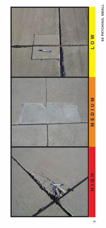
PATCHING, SMALL (LESS THAN 5.5 FT2 (0.5 M2)) (66)
Description A patch is an area where the original pavement has been removed and replaced by a filler material. For condition evaluation, patching is divided into two types: small (less than 5.5 square feet (0.5 square meters)) and large (over 5.5 square feet (0.5 square meters)). Large patches are described in the next section.
Severity Levels
L Patch is functioning well, with little or no deterioration.
M Patch has deteriorated, and/ or moderate spalling can be seen around the edges. Patch material can be dislodged, with considerable effort (minor FOD potential).
H Patch has deteriorated, either by spalling around the patch or cracking within the patch, to a state which warrants replacement.
How To MeasureIf one or more small patches having the same severity level are located in a slab, it is counted as one slab containing that distress. If more than one severity level occurs, it is counted as one slab with the higher severity level being recorded. If a crack is repaired by a narrow patch (e.g., 4 to 10 inches (100 to 250 mm) wide), only the crack and not the patch should be recorded at the appropriate severity level. If the original distress of a patch is more severe than the patch itself, the original distress type should be recorded.
19
66 P
ATC
HIN
G, S
MA
LL
L O
WM
E D
I U
MH
I G
H

20
PATCHING, LARGE (OVER 5.5 FT2 (0.5 M2)) AND UTILITY CUT (67)
DescriptionPatching is the same as defined in the previous section. A utility cut is a patch that has replaced the original pavement because of placement of underground utilities. The severity levels of a utility cut are the same as those for regular patching.
Severity Levels
L Patch is functioning well with very little or no deterioration.
M Patch has deteriorated and/ or moderate spalling can be seen around the edges. Patch material can be dislodged with considerable effort, causing some FOD potential.
H Patch has deteriorated to a state which causes considerable roughness and/ or high FOD potential. The extent of the deterioration warrants replacement of the patch.
How To Count The criteria are the same as for small patches.

21
GE
, LA
RTC
HIN
GA
67 P
L O
WM
E D
I U
MH
I G
H
22
POPOUTS (68)
Description A popout is a small piece of pavement that breaks loose from the surface due to freeze-thaw action in combination with expansive aggregates. Popouts usually range from approximately 1 inch (25 mm) to 4 inches (100 mm) in diameter and from 1/2 inch (13 mm) to 2 inches (50 mm) deep.
Severity LevelsNo degrees of severity are defined for popouts. However, popouts must be extensive before they are counted as a distress; i.e., average popout density must exceed approximately three popouts per square yard (square meter) over the entire slab area.
How To Count The density of the distress must be measured. If there is any doubt about the average being greater than three popouts per square yard (square meter), at least three, random, 1 square yard (1 square meter) areas should be checked. When the average is greater than this density, the slab is counted.

23
68 P
OP
OU
TS
24
PUMPING (69)
Description Pumping is the ejection of material by water through joints or cracks caused by deflection of the slab under passing loads. As the water is ejected, it carries particles of gravel, sand, clay, or silt and results in a progressive loss of pavement support. Surface staining and base or subgrade material on the pavement close to joints or cracks are evidence of pumping. Pumping near joints indicates poor joint sealer and loss of support which will lead to cracking under repeated loads. The joint seal must be identified as defective before pumping can be said to exist. Pumping can occur at cracks as well as joints.
Severity LevelsNo degrees of severity are defined. It is sufficient to indicate that pumping exists.
How To CountSlabs are counted as follows: one pumping joint between two slabs is counted as two slabs. However, if the remaining joints around the slab are also pumping, one slab is added per additional pumping joint.

25
69 P
UM
PIN
G

26
SCALING (70)
Description Surface deterioration caused by construction defects, material defects and environmental factors. Generally scaling is exhibited by delamination or disintegration of the slab surface to the depth of the defect.
Construction defects include: over-finishing, addition of water to the pavement surface during finishing, lack of curing, attempted surface repairs of fresh concrete with mortar. Generally this occurs over a portion of a slab.
Material defects include: inadequate air entrainment for the climate. Generally this occurs over several slabs that were affected by the concrete batches.
Environmental factors: freezing of concrete before adequate strength gained or thermal cycles from certain aircraft. Generally over a large area for freezing, and isolated areas for thermal effects.
Typically, the FOD from scaling is removed by sweeping, but the concrete will continue to scale until the affected depth is removed or expended.
Severity Levels
L Minimal loss of surface paste that poses no FOD hazard. No FOD potential.
M The loss of surface paste that poses some FOD potential including isolated fragments of loose mortar, exposure of the sides of coarse aggregate (less than 1/4 of the width of coarse aggregate), or evidence of coarse aggregate coming loose from the surface.
H The high severity is associated with low durability concrete that will continue to pose a high FOD hazard; normally the layer of surface mortar is observable at the perimeter of the scaled area, and is likely to continue to scale due to environmental or other factors. Indication of high severity FOD is that routine sweeping is not sufficient to avoid FOD issues.
How To Count If two or more levels of severity exist on a slab, the slab is counted as one slab having the maximum level of severity. If “D” cracking or ASR is counted, scaling is not counted.

27
70 S
CA
LIN
G
L O
WM
E D
I U
MH
I G
H

28
SETTLEMENT OR FAULTING (71)
DescriptionSettlement or faulting is a difference of elevation at a joint or crack caused by upheaval or consolidation.
Severity LevelsSeverity levels are defined by the difference in elevation across the fault and the associated decrease in ride quality and safety as severity increases.
Difference In Elevation
Severity Runways/ Taxiways Aprons
L < 1/4 inch (< 6 mm)
1/8 – 1/2 inch(3 – 13 mm)
M 1/4 – 1/2 inch(6 – 13 mm)
1/2 - 1 inch(13 – 25 mm)
H > 1/2 inch(> 13 mm)
> 1 inch(> 25 mm)
How To CountIn counting settlement, a fault between two slabs is counted as one slab. A straightedge or level should be used to aid in measuring the difference in elevation between the two slabs.
Construction-induced elevation differential is not rated in PCI procedures. Where construction differential exists, it can often be identified by the way the high side of the joint was rolled down by finishers (usually within 6 inches (150 mm) of the joint) to meet the low-slab elevation.

29
71 S
ET
TLE
ME
NT
L O
WM
E D
I U
MH
I G
H

30
SHATTERED SLAB/ INTERSECTING CRACKS (72)
Description Intersecting cracks are cracks that break the slab into four or more pieces because of overloading and/ or inadequate support. The high severity level of this distress type, as defined below, is referred to as a shattered slab. If all pieces or cracks are contained within a corner break, the distress is categorized as a severe corner break.
Severity Levels
L Slab is broken into four or five pieces predominantly defined by low severity cracks.
M (1) Slab is broken into four or five pieces with over 15 percent of the cracks of medium severity (no high severity cracks); or (2) slab is broken into six or more pieces with over 85 percent of the cracks of low severity.
H At this level of severity, the slab is called shattered: (1) slab is broken into four or five pieces with some or all of the cracks of high severity; (2) slab is broken into six or more pieces with over 15 percent of the cracks of medium or high severity.
How To CountNo other distress such as scaling, spalling, or durability cracking should be recorded if the slab is medium or high severity level, since the severity of this distress would affect the slab’s rating substantially. Shrinkage cracks should not be counted in determining whether or not the slab is broken into four or more pieces.

31
72 S
HA
TT
ER
ED
SLA
B
L O
WM
E D
I U
MH
I G
H

32
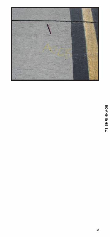
SHRINKAGE CRACKS (73)
Description Shrinkage cracks are hairline cracks that are usually only a few feet long and do not extend across the entire slab. They are formed during the setting and curing of the concrete and usually do not extend through the depth of the slab.
Severity Levels No degrees of severity are defined. It is sufficient to indicate that shrinkage cracks exist.
How To Count If one or more shrinkage cracks exist on one particular slab, the slab is counted as one slab with shrinkage cracks.
33
73 S
HR
INK
AG
E

34
SPALLING (TRANSVERSE AND LONGITUDINAL JOINTS) (74)
Description Joint spalling is the breakdown of the slab edges within 2 feet (60 mm) of the side of the joint. A joint spall usually does not extend vertically through the slab but intersects the joint at an angle. Spalling results from excessive stresses at the joint or crack caused by infiltration of incompressible materials or traffic loads. Weak concrete at the joint (caused by overworking) combined with traffic loads also causes spalling.
Frayed condition as used in this test method indicates material is no longer in place along a joint or crack. Spalling indicates material may or may not be missing along a joint or crack.
Severity Levels
Spall Length Description
L
< 2 feet(600 mm)
spall is broken into pieces or fragmented; little FOD or tire damage potential exists.
> 2 feet(600 mm)
(a) spall is broken into no more than three pieces defined by low or medium severity cracks; little or no FOD potential exists; or (b) joint is lightly frayed; little or no FOD potential exists.
M
< 2 feet(600 mm)
spall is broken into pieces or fragmented, with some of the pieces loose or absent, causing considerable FOD or tire damage potential.
> 2 feet(600 mm)
(a) spall is broken into more than three pieces defined by light or medium cracks; (b) spall is broken into no more than three pieces with one or more of the cracks being severe with some FOD potential existing; or (c) joint is moderately frayed, with some FOD potential.
H > 2 feet(600 mm)
(1) spall is broken into more than three pieces defined by one or more high sever-ity cracks with high FOD potential; or (2) joint is severely frayed, with high FOD potential.
How To Count If the joint spall is located along the edge of one slab, it is counted as one slab with joint spalling. If spalling is located on more than one edge of the same slab, the edge having the highest severity is counted and recorded as one slab. Joint spalling can also occur along the edges of two adjacent slabs. If this is the case, each slab is counted as having joint spalling. If a joint spall is small enough to be filled during a joint seal repair, it should not be recorded.

35
74 S
PALL
ING
, JO
INT
L O
WM
E D
I U
MH
I G
H

36
SPALLING (CORNER) (75)
Description Corner spalling is the raveling or breakdown of the slab within approximately 2 feet (600 mm) of the corner. A corner spall differs from the corner break in that the spall angles downward to intersect the joint, while a break extends vertically through the slab.
Severity Levels
L One of the following conditions exists: (1) spall is broken into one or two pieces defined by low severity cracks (little or no FOD potential), (2) spall is defined by one medium severity crack (little or no FOD potential).
M One of the following conditions exists: (1) spall is broken into two or more pieces defined by medium severity crack(s), and a few small fragments may be absent or loose; (2) spall is defined by one severe, fragmented crack that may be accompanied by a few hairline cracks; or (3) spall has deteriorated to the point where loose material is causing some FOD potential.
H One of the following conditions exists: (1) spall is broken into two or more pieces defined by high severity fragmented crack(s), with loose or absent fragments; (2) pieces of the spall have been displaced to the extent that a tire damage hazard exists; or (3) spall has deteriorated to the point where loose material is causing high FOD potential.
How To Count If one or more corner spalls having the same severity level are located in a slab, the slab is counted as one slab with corner spalling. If more than one severity level occurs, it is counted as one slab having the higher severity level.
A corner spall smaller than 3 inches (76 mm) wide, measured from the edge of the slab and filled with sealant, is not recorded.

37
75 S
PALL
ING
, CO
RN
ER
M E
D I
U M
L O
WM
E D
I U
MH
I G
H

38
ALKALI SILICA REACTION (ASR) (76)
Description ASR is caused by chemical reaction between alkalis and certain reactive silica minerals which form a gel. The gel absorbs water, causing expansion which may damage the concrete and adjacent structures. Alkalis are most often introduced by the portland cement within the pavement. ASR cracking may be accelerated by chemical pavement deicers.
Visual indicators that ASR may be present include:
1. Cracking of the concrete pavement (often in a map pattern)
2. White, brown, gray or other colored gel or staining may be present at the crack surface
3. Aggregate popouts
4. Increase in concrete volume (expansion) that may result in distortion of adjacent or integral structures or physical elements. Examples of expansion include shoving of asphalt pavements, light can tilting, slab faulting, joint misalignment, and extrusion of joint seals or expansion joint fillers.
Because ASR is material-dependent, ASR is generally present throughout the pavement section. Coring and concrete petrographic analysis is the only definitive method to confirm the presence of ASR. The following should be kept in mind when identifying the presence of ASR through visual inspection:
1. Generally ASR distresses are not observed in the first few years after construction. In contrast, plastic shrinkage cracking can occur the day of construction and is apparent within the first year.
2. ASR is differentiated from D-Cracking by the presence of cracking perpendicular to the joint face. D-Cracking predominantly develops as a series of parallel cracks to joint faces and linear cracking within the slab.
3. ASR is differentiated from Map Cracking/ Scaling by the presence of visual signs of expansion.
Severity Levels
L Minimal to no Foreign Object Damage (FOD) potential from cracks, joints or ASR related popouts; cracks at the surface are tight (predominantly 1 mm or less). Little to no evidence of movement in pavement or surrounding structures or elements.
M Some FOD potential; increased sweeping or other FOD removal methods may be required. May be evidence of slab movement and/ or some damage to adjacent structures or elements.
Medium ASR distress is differentiated from low by having one or more of the following: increased FOD potential, increased cracking of the slab, some fragments along cracks or at crack intersections present, surface popouts of concrete may occur, pattern of wider cracks (predominantly 1 mm or wider) that may be subdivided by tighter cracks.
H One or both of the following exist: 1) Loose or missing concrete fragments which pose high FOD potential, 2) Slab surface integrity and function significantly degraded and pavement requires immediate repair; may also require repairs to adjacent structures or elements.
How To Count No other distresses should be recorded if high severity ASR is recorded.

39
76 A
SR
L O
WM
E D
I U
MH
I G
H