concrete syntax definition for modeling languages - infoscience
TRANSCRIPT

THÈSE NO 3927 (2007)
ÉCOLE POLYTECHNIQUE FÉDÉRALE DE LAUSANNE
PRÉSENTÉE LE 2 NOvEMBRE 2007
À LA FACULTÉ INFORMATIQUE ET COMMUNICATIONS
Institut des systèmes informatiques et multimédias
PROGRAMME DOCTORAL EN INFORMATIQUE, COMMUNICATIONS ET INFORMATION

Abstract
Abstract
Model Driven Engineering (MDE) promotes the use of models as primary artefacts of a software development process, as an attempt to handle complexity through abstraction, e.g. to cope with the evolution of execution platforms. MDE follows a stepwise approach, by prescribing to develop abstract models further improved to integrate little by little details relative to the final deployment platforms. Thus, the application of an MDE process results in various models residing at various levels of abstraction.
Each one of these models is expressed in a modeling language, in which one may find appropriate concepts for the abstraction level considered. Many advocate to use the right (modeling) language for the right purpose. This means that it is sometimes better approach to use small languages specific to the considered domain and abstraction level, than to use general purpose languages (e.g. UML) when they do not perfectly fit the (modeling) needs. As a matter of fact, an MDE development process, which involves many different domains and abstraction levels, should also involve a large variety of modeling languages. Project managers who want to apply an MDE process need to deal with this language proliferation to such an extent that, in the long run, one may infer that language engineers can become major actors of software development teams.
We believe that comprehensive modeling language management facilities may con-siderably alleviate that MDE drawback. Such facilities may include modeling language def-inition, extension, adaptation, or composition. To define a (modeling) language, one need to define its abstract syntax, its semantics, and one or more concrete syntaxes. This thesis focuses on concrete syntax definition for modeling languages, when the abstract syntax is given in the form of a metamodel. We will provide solutions both for textual and graphical concrete syntaxes.
Some of our experiences in building textual languages (as MTL, a model transforma-tion language), and graphical languages (as Netsilon, a web-application modeler) has shown that a lot of work was spent in implementing interface using traditional techniques, be it a text processor generated from a compiler compiler specification, or a modeler making use of modern 2D graphical libraries. Indeed, abstract and concrete syntax were implemented in a disconnected way, and it was then necessary to assemble them, which became rapidly clumsy while abstract syntax evolved.
We built our solution to concrete syntax definition as companions of the abstract syn-tax. The definition of concrete syntax we propose here made it possible to build automatic tools able to analyze or synthesize models from/to text, and to create graphical modelers. We will present a metamodel for textual concrete syntax definition to construct constructive reversible grammars. We will also propose a technique for graphical concrete syntax defini-tion following a two-step process: specification and realization. Specification is a restrictive approach in which a metamodel defines a graphical concrete syntax. Both relations with
i

Keywords
abstract syntax and spatial relationships are expressed by means of constraints. The realiza-tion step proposes a way to provide the concrete syntax tree a meaning, by attributing it a graphical appearance, and by expressing possible user interactions.
The structure of the document is the following. After introducing in deeper details the problem and the general structure of the solution we propose, we will take a tour of MDE, text and graph grammars. Then, we will present Netsilon as an example of an MDE tool to MDE development, which required both the definition of a graphical and a textual modeling language. The two following sections will present the solutions we propose for textual and graphical concrete syntax definition, respectively. Final remarks and possible improve-ments, especially regarding reusability in general of MDE meta-artifacts (like metamodels or model transformations), and of concrete syntax in particular, will conclude the document.
Keywords
Model Driven Engineering, Metamodeling, Language Engineering, Concrete Syntax, Tex-tual Concrete Syntax, Graphical Concrete Syntax, Scalable Vector Graphics.
ii

Version Abrégée
Version Abrégée
L'ingénierie dirigée par les modèles (IDM) promeut les modèles comme composants princi-paux d’un processus de développement logiciel. Cette approche tente d’organiser la com-plexité par l’abstraction, par exemple afin de faire face à l’évolution des plate-formes d’exécution. L’IDM suit une approche par étapes dans laquelle sont développés des modèles abstraits, peu à peu améliorés pour y intégrer les détails dont a besoin la plate-forme de déploiement finale. Ainsi l’application d’un processus IDM produit une multitude de modè-les à différent niveaux d’abstraction.
Chacun de ces modèles est exprimé dans un langage supposé apporter les concepts adéquats pour le niveau d’abstraction considéré. De nombreux auteurs préconisent d’utiliser le langage (de modélisation) le plus adapté possible au but poursuivi. En d’autre termes, il est souvent plus ingénieux d’utiliser de petits langages très spécialisés pour un domaine et un niveau d’abstraction donné, que d’utiliser des langages génériques (tels UML) quand ils ne satisfont pas pleinement au besoins de la modélisation. C’est pourquoi un processus de développement IDM, qui implique de nombreux domaines et niveaux d’abstraction, doit souvent impliquer de nombreux langages. Les chefs de projets désireux d’adopter une approche IDM se voient donc dans l’obligation de jongler avec une véritable prolifération de langages, ceci à tel point qu’on est en droit de se demander si les ingénieurs du langage ne seront pas les partenaires indispensables des équipes de développement logiciel du futur.
L’idée développée dans ce document est qu’un mécanisme générique de gestion de ces nombreux langages simplifierait sans doute cette situation spécifique à l’IDM. De tels mécanismes seraient par exemple capables de définir complètement des langages de modé-lisation, de les étendre ou les adapter, voire de les composer. Pour définir un langage, qu’il s’agisse d’un langage de modélisation ou non, il est nécessaire de spécifier sa syntaxe abs-traite, au moins une syntaxe concrète et sa sémantique. Cette thèse s’intéresse à la définition de syntaxes concrètes, une fois la syntaxe abstraite établie sous forme de métamodèle. Ces syntaxes concrètes peuvent être soit textuelles, soit graphiques.
Certaines de nos expériences dans la construction de langages textuels (comme MTL, un langage de transformation de modèles) ou graphiques (tel Netsilon, un modeleur d’appli-cation internet) ont montré que beaucoup d’énergie est dépensée dans l’implémentation des interfaces utilisateur, qu’il s’agisse de processeurs de texte générés à partir de spécifications pour compilateur de compilateurs, ou de modeleurs créés à partir de bibliothèques pour la représentation graphique en deux dimensions. En effet, dans ces projets, les syntaxes abs-traites et concrètes sont développées de manière indépendante, ce qui pose rapidement des problèmes en terme de cohérence lors des évolutions de la syntaxe abstraite.
Les solutions proposées ici définissent les syntaxes concrètes comme dépendantes des syntaxes abstraites. Il a été possible de construire des implémentations prototypes basées sur les approches proposées. L’une d’elle est capable de produire du texte à partir d’un
iii

Mots Clefs
modèle, ou inversement un modèle à partir d’un texte. Une autre est capable de fournir un modeleur graphique maintenant en cohérence un modèle et sa représentation graphique. La première contribution de cette thèse est la définition d’un métamodèle pour la spécification constructive de syntaxes textuelles réversibles. La seconde contribution est une méthode de spécification de syntaxes graphiques en deux étapes: l’étape de spécification et l’étape de réalisation. La spécification suit une approche restrictive dans laquelle un métamodèle défi-nit la structure d’un graphe de syntaxe concrète. Des contraintes viennent en complément afin d’exprimer la cohérence entre les syntaxes concrète et abstraite, ainsi que les règles de composition spatiale. L’étape de réalisation consiste à préciser le mode de représentation du graphe de syntaxe concrète, ainsi que des interactions possibles avec un utilisateur souhai-tant modéliser un système.
Après une brève introduction, ce document commencera par un aperçu de l’IDM ainsi que des techniques communément acceptées de spécification de syntaxes concrètes textuel-les et graphiques. Nous verrons ensuite l’outil Netsilon, qui est un exemple d’outil de modé-lisation pour l’IDM: nous pourrons alors avoir un exemple de démarche IDM et de spécification de langages textuels et graphiques. Nous en déduirons de possibles améliora-tions dans la construction d’outils pour l’IDM basés sur les langages. Les deux chapitres suivants décriront les approches proposées pour la spécification de syntaxes textuelles et graphiques. Enfin, nous conclurons sur les améliorations à apporter aux approches propo-sées, notamment en ce qui concerne la réutilisabilité des artefacts des méthodes de type IDM en général (par exemple les métamodèles ou les transformations de modèles), et des syntaxes concrètes en particulier.
Mots Clefs
Ingénierie Dirigée par les Modèles, Métamodélisation, Ingénierie des Langages, Syntaxes Concrètes, Syntaxes Textuelles, Syntaxes Graphiques, Scalable Vector Graphics.
iv

Acknowledgements
Acknowledgements
First of all, I need to apologize to the reader of this document for that I used the English lan-guage that I poorly master. So best thanks to all those readers who will manage to ignore all these «implementation» defects that appear all along the document.
Obviously, a thesis is never the matter of a single person. It is especially true regard-ing this one. So, though I appear as the "main" author of this thesis, I want to acknowledge the following people.
First, this thesis was possible to start. Prof. Alfred Strohmeier accepted my applica-tion for this doctoral assistant position that I found thanks to Google using a search criteria like uml ocl "offre d’emploi". He accepted me regarding my work on the MTL language, which was possible thanks to Prof. Jean-Marc Jézéquel, who in turn accepted me regarding my work on Netsilon, which was possible thanks to Dr. Pierre-Alain Muller.
This thesis was also possible to continue when Prof. Strohmeier acceded to his new responsibilities of rector at the university of Neuchâtel. I am very grateful to Dr. Thomas Baar for receiving me as a doctoral student. I also want to thank him for freedom he let me in my work.
As an apprentice researcher, I needed advisors from which I could learn and who could introduce me to the scientific community. If Thomas helped me a lot, I also want to acknowledge Dr. Pierre-Alain Muller and Dr. Raul Silaghi.
I also would like to thank all those people with whom a valuable scientific collabora-tion was possible, but I’m afraid I will not be able to mention them all here. Nevertheless, I would like to cite Dr. Raul Silaghi, Dr. Pierre-Alain Muller, Dr. Thomas Baar, and Slavisa Markovic. Some other people helped me a lot in engineering and implementing ideas pre-sented here: Prof. Michel Hassenforder, Rémi Schnekenburger, Fabrice Hong, Fabien Rohrer, François Helg, and Amit Raj.
This thesis was also financially supported: thanks to the Hasler foundation, INTER-REG (i.e. European Union and Switzerland), EPFL, PUBLICA, and CFC. Thanks also to the ENSISA, which provided me with an office where I could write this document.
Finally, this thesis could be defended, so thanks a lot to the reviewers who accepted to dive into the details of the present document: Dr. Thomas Baar, Prof. Bernhard Rumpe, Prof. Alain Wegmann, and Prof. Emre Telatar. I am also very grateful to Dr. Alban Rasse and Slavisa Markovic for reading over that document and who helped in improving it. Again, special thanks to Dr. Pierre-Alain Muller for providing abundant advice all along (and before) the thesis, including regarding the dissertation.
v

List of Figures
List of Figures
Chapter 1: IntroductionFigure 1.1: Concrete Syntax for Metamodel-Based Languages ........................ 5Figure 1.2: Concrete Syntax for Metamodel-Based Languages Revisited........ 7
Chapter 2: Language Driven EngineeringFigure 2.1: LDE Concept of Successive Improvements.................................... 12Figure 2.2: The V Model ................................................................................... 13Figure 2.3: M1: A Relational Database Language Sentence ............................. 18Figure 2.4: M2: Relational Database Language Abstract Syntax...................... 19Figure 2.5: M1 conforming to M2: Figure 2.3 as an ASG (Excerpt) ................ 19Figure 2.6: M2 conforming to M3: Figure 2.4 as a MOF ASG (Excerpt)......... 20Figure 2.7: M3: MOF 1.4 (© OMG).................................................................. 21
Chapter 3: Netsilon: LDE Example and Embryonic Solution
Figure 3.1: Web Application Modeling with Netsilon ...................................... 34Figure 3.2: Netsilon Set of Models .................................................................... 35Figure 3.3: An Example of Business Model...................................................... 36Figure 3.4: Hypertext Model for Listing People................................................ 38Figure 3.5: Genealogy Web Application at Work ............................................. 39Figure 3.6: Hypertext Model for personInList................................................. 39Figure 3.7: Implementing Person::marry in Xion ............................................ 41Figure 3.8: Sisters found by a Xion Expression ................................................ 42Figure 3.9: Hypertext Metamodel (Excerpt)...................................................... 43Figure 3.10: Deployment Metamodel (Excerpt).................................................. 44Figure 3.11: Code Generation Process ................................................................ 45Figure 3.12: Simplified UML Class Diagrams Metamodel................................. 47Figure 3.13: Diagramming Framework ............................................................... 49Figure 3.14: Attribute Representation Element ................................................. 51Figure 3.15: Classifier Representation Element ............................................... 52Figure 3.16: Generalization Representation Element ........................................ 53Figure 3.17: getSpecializationConnector Xion Implementation...................... 54Figure 3.18: Attribute Representation Presentation Model ............................... 54Figure 3.19: Classifier Representation Hypertext Model (Excerpt) ................. 55Figure 3.20: Classifier Main Representation Presentation Model .................... 55Figure 3.21: Generalization Representation Presentation Model ...................... 56Figure 3.22: An Example Model for Figure 3.3 .................................................. 57Figure 3.23: An Example Representation Model for Figure 3.22 ....................... 58
xi

List of Figures
Figure 3.24: Graphical Representation for Figure 3.23 ....................................... 59Figure 3.25: The Netsilon LDE Process .............................................................. 60
Chapter 4: Textual Concrete SyntaxFigure 4.1: Model-Based Compiler Architecture .............................................. 66Figure 4.2: Abstract Syntax of a Simple Language ........................................... 68Figure 4.3: Example of Model and a Expected Textual Representation ........... 69Figure 4.4: Automatic Bidirectional Model Representation.............................. 71Figure 4.5: Overview of the Metamodel for Textual Concrete Syntax ............. 72Figure 4.7: Variation with Top-Level Reusable Templates .............................. 76Figure 4.6: Straightforward Textual Concrete Syntax Model ........................... 77Figure 4.8: The Simplified Statechart Metamodel............................................. 78Figure 4.9: A Statechart Sentence and a Textual Representation...................... 79Figure 4.10: Textual Concrete Syntax Specification for the Statechart Language 80
Chapter 5: Graphical Concrete SyntaxFigure 5.1: General Architecture ....................................................................... 85Figure 5.2: Symbols for the Statechart Concepts .............................................. 86Figure 5.3: A Statechart Sentence and its Graphical Representation ................ 86Figure 5.4: The Chessboard Metamodel............................................................ 87Figure 5.5: An Incorrect Chessboard Model ..................................................... 88Figure 5.6: A Chessboard Sentence ................................................................... 89Figure 5.7: Scheme Definition Architecture...................................................... 91Figure 5.8: Statechart Schemes.......................................................................... 92Figure 5.9: The Composite State and Transition Icons ..................................... 94Figure 5.10: The Chessboard Schemes................................................................ 98Figure 5.11: The Board and Square Icons ........................................................... 99Figure 5.12: SVG Templates for Statecharts ....................................................... 103Figure 5.13: SimpleState SVG Template:
CSVG Constraint to Handle Text Growth ...................................... 104Figure 5.14: Conceptual Architecture of DOM Interfaces .................................. 106Figure 5.15: SimpleState SVG Template: Declaring DOM Components .......... 109Figure 5.16: Transition SVG Template: Declaring DOM Components ............ 109Figure 5.17: JMI Initialization Script .................................................................. 112Figure 5.18: SimpleState SVG Template: Creation Reaction............................. 112Figure 5.19: SimpleState SVG Template: onStick Reaction ............................. 115Figure 5.20: SimpleState SVG Template: Updater............................................. 117Figure 5.21: Initial View of the Prototye Implementation................................... 119Figure 5.22: Simple State Template Instantiated................................................. 119Figure 5.23: SVG File for a Single Simple State Instance .................................. 120Figure 5.24: XMI File for a Single Simple State Instance................................... 121
xii
List of Figures
Figure 5.25: The Door State Machine Described in the Tool.............................. 122
Chapter 6: ConclusionAppendix A: Applying and Customizing LDE
Figure A.1: The MTL Compilation Process ....................................................... 133Figure A.2: Refinement Steps to Integrate a Distribution Concern with UML.. 134Figure A.3: The Bank Example .......................................................................... 135Figure A.4: Refinement Process in Enterprise Fondue ...................................... 138Figure A.5: MDA-Oriented Hierarchy of UML-D Profiles ............................... 139Figure A.6: The MTL1-D Transformation: Exploring Operations Part................. 144Figure A.7: The MTL1-D Outcome for the Bank Example................................... 145Figure A.8: The MTL2-D Transformation: Creating Exposition Part ................... 147Figure A.9: The MTL2-D Outcome for the Bank Example................................... 148Figure A.10: Customizing an LDE Process.......................................................... 149Figure A.11: Refining along the Distribution, RMI-Technology,
and Java-Language Concern-Dimensions ....................................... 153Figure A.12: The MTL Weaving Process............................................................. 154Figure A.13: Snippets of the MTL1-D-Aspect ........................................................ 156Figure A.14: MTL Weaver Snippets for Class Merge (mergeClass) ................... 158Figure A.15: Predefined MTL-Aspect Tags ......................................................... 159Figure A.16: Snippets of the Copy Input Library .................................................. 160Figure A.17: Snippets of the Distribution Output Library................................. 162
xiii

List of Figures
xiv

Introduction
Chapter 1:
Introduction
1.1 Promoting Abstraction through Languages
The continuous evolution of hardware towards more and more execution speed and mem-ory capacity paved the way to more and more complex software. Software engineering was born almost 40 years ago, when it became clear that software development could not be conducted anymore without engineering guidance and specific techniques, such as software development methods, execution platforms and abstraction mechanisms.
Methods intend to state clearly the steps to be taken to develop a software system. They identify the various stakeholders (e.g. business analyst, software architect, software developer) and their respective roles and duties. Methods help organizing tasks of team members for both producing and maintaining software systems. Methods range from very precise techniques designed for developing well-defined systems with an emphasis on reli-ability (e.g. B [Abr96]), to collections of informal best practices intended for rapid applica-tion development of systems with highly evolving requirements (e.g. eXtreme Programming [BA04]).
Platforms are layered collections of reusable software or hardware components intended to support further layers of software. They offer well defined services that can be accessed by connected software through well-agreed upon collections of interfaces. Plat-forms can be of very different natures: examples for kinds of platforms are processors, which offer sets of instructions, operating systems, which offer a common mean to access to categories of hardware (including processors) and organize process flows (e.g. POSIX), vir-tual machines, which offer a common behavior on different operating systems (e.g. JRE as implemented for various operating systems), and object request brokers, which facilitate the collaboration of distributed and heterogeneous software components (e.g. CORBA [ABB+04]).
Abstraction, in a general sense, is a mental selection mechanism intended to discard information that is not relevant at a given point in time. As such, abstraction is a cornerstone of software engineering techniques and methods. As a matter of fact, abstraction allows engineering systems by concentrating first on core business functionalities while deferring secondary concerns like details of final execution platform. The details discarded earlier are introduced later on in the system by "lowering the level of abstraction", either by evolution or by refinement. Platforms are examples for supporting abstraction in software engineer-ing, in that offered interfaces actually hide implementation details to the client software sys-tem. Introducing abstraction in software system engineering can be achieved either
1
Promoting Abstraction through Languages
explicitly via interfaces of platforms, or implicitly by embedding specific concepts in lan-guages.
In the explicit case, interfaces are collected in libraries that can be used in program code. An evolution of explicit use of platform is Component Oriented Programming [Szy02], which fragments computer systems into a framework of different software compo-nents interrelated through their interfaces. Platforms are here considered as already devel-oped ("off-the-shelf") components, following the example of the CORBA platform which offers a predefined set of interfaces (e.g. in [BDII02] and in [ABH+00]). However, the explicit use of platform becomes tedious as soon as platforms become more complex [CBR03]. For instance, «popular middleware platforms, such as J2EE, .NET, and CORBA, contain thousands of classes and methods with many intricate dependencies and subtle side effects that require considerable effort to program and tune properly. Moreover, since these platforms often evolve rapidly —and new platforms appear regularly— developers expend considerable effort manually porting application code to different platforms or newer ver-sions of the same platform» [Sch06].
In the implicit case, services offered by platforms are conceptualized and made avail-able via constructs of a specific artificial language (as the opposite of natural language), be it a modeling language or a programming language. In the case of executable languages, language statements (i.e. language sentences) are either interpreted by a system that refers to the platform, or compiled into another language that makes less assumptions about the peculiarities of the platform. In both cases, additional information about the platform is required.
The hierarchy of programming languages is a good example of abstraction through languages. Basically, hardware processors interpret instructions written in a language with only two lexemes: true and false. For computer systems to be easier to program by humans, patterns of binary instructions were abstracted in assembly languages (one per kind of pro-cessor), which define concepts such as register, instruction, or datum. Assembly code can be compiled back into a stream of true/false lexemes so that the processor (platform) can execute the specification. The pattern applies again for 3GL languages (e.g. Fortran, C) that are compiled into assembly languages, and that embed concepts such as function or struc-ture. An interesting result is code portability across platforms: a C specification may be compiled for various kinds of processors that offer similar behavior yet offering different instruction sets. Note that a 3GL language may be defined on top of another 3GL language (e.g. C++ on top of C). 4GL languages apply the pattern once more and leave the program-matic technological space to offer concepts closer to the problem domain. The idea was fur-ther emphasized in Domain Specific Languages (DSLs) [KMB+96].
Another such illustration of practical use of abstraction is modeling. A model is a sim-plification of a system valid in certain circumstances, and that is easier to reason on, i.e. eas-ier to engineer, manipulate, communicate, etc. Again, a model is expressed in a given (modeling) language that captures abstraction through specific concepts. Model Driven
2

Introduction
Engineering (MDE - [Ken02]) and related techniques ([GSCK04], [MCF03], etc.) promote the systematic use of models in the software lifecycle. A model resides at a given level of abstraction regarding platform dependency. Platforms for computer systems (web applica-tion servers, database servers, ORB frameworks, operating systems, etc.) appear and evolve very rapidly. While a given category of platforms embrace a given number of common con-cepts, each platform has its specificities that computer systems need to deal with. By the systematic use of models, computer system developers can first concentrate on an abstract model to describe the core business. Further activities concretize the model (as the opposite of abstract) either by improving the model or by building new models to integrate details about how the final system may integrate the platform(s). An important advantage of MDE-like technique is that they provide means to automate the concretization mechanism, fol-lowing the example of compilers for 3GL languages. Note that the decision of the final plat-form is not taken yet at the time the abstract model is developed, and that the abstract model may be reused to target different platforms. As we will see in section 2.1.1 on page 11, one may even see MDE-like technologies as a mean to formalize at least part of a method, by stating, using formal specifications, the flow of models to develop and improvements to bring them. Moreover, especially if one introduces the notion of abstract platform [ADvSP04], one may develop a system specification taking the form of a model that can serve to target different platforms. As a summary, this promising way makes it possible to develop software systems taking advantage of abstraction as offered by modeling lan-guages, handle introduction of platforms, and even provide support for methodology.
MDE-like techniques propose abstraction through modeling languages. To do so, two philosophies are possible. General purpose modeling languages, like UML [AAB+07], offer a common mean to model systems of very different natures. Advantage is that those (usually broad) languages can be used to model different systems once those languages are mastered by actors of development project. Moreover models are easier to understand when it comes to maintenance. General purpose languages are often well supported by tools. A problem is that the concepts they propose fit only partially the demands of the system domain(s). The second philosophy, as proposed in [CESW05] or in [KSLB03], is to apply the experience gained in the domain of specific languages to modeling, by defining specific modeling languages dedicated to the domain of the system under study. Developing system using such domain specific languages is called Domain Specific Modeling (DSM, e.g. in [Poh03]). In the software development lifecycle, which implies various models of various domains at various levels of abstraction, making use of a DSM approach implies the use of a large number of DSLs. The problem is that the target audience of a domain specific mod-eling language is rather small, making it hardly affordable to develop dedicated tools to sup-port DSLs. Examples for such tools are modeling environments (graphical Computer-Aided Software Development tools, CASE tools in short, or textual Integrated Development Envi-ronments - IDEs in short), interpreters or transformers to executable languages.
3

Motivations
To apply a DSM development process, a project architect needs to define all those DSLs that have to be used, how they relate to each other (e.g. transformation between two DSLs, or usage of a DSL within another), and under which circumstances they are applied. While MDE is designed to manage complexity of software and platforms, it tends however to make more complex the task of project management. The problem is even more complex if some of these languages need to be customized.
In the past, such proliferation of languages, with lack of interconnected tool support, put a break on the development of DSL usage [Iiv96]. The novelty brought by MDE-like technologies is to ease development of such languages and tools. Two key technologies are at the core of the MDE-like technologies: metamodeling and model transformation. Meta-modeling makes it possible to define the abstract syntax of languages. A metamodel is the placeholder for modeling static concepts of a language (i.e. its vocabulary) and theirs rela-tions (i.e. the taxonomy). A sentence of a language is embodied by a model that conforms to the metamodel of this language, i.e. structure of the model graph follows directives of the metamodel. By its graph nature, one may call the model the abstract syntax graph. Model transformations may express behavior of the language by stating how models may be manipulated. Model transformations, for their definition, rely on the metamodel of the transformed models. Model transformations may be used for various purposes: transform-ing a model of a given language into a model of another language, adding information into a model, mixing models of a same language, making a model evolve according to an event, etc.
A language is defined by its abstract syntax, its semantics, and as much concrete syn-taxes as necessary. In the context of MDE-like technologies, metamodeling addresses that issue of defining the abstract syntax. Different solutions to capture semantics have been proposed (e.g. using model transformations [KW03, MB06]), but semantics specification is still subject to discussions [HR04]. The problem of concrete syntax has recently gained interest in the MDE community.
In this thesis, we concentrate on the definition of concrete syntaxes for languages whose abstract syntax is already provided as a metamodel. We investigate specification techniques (for both textual and graphical languages) that must be precise enough for an automatic tool to provide a modeling environment (CASE or IDE). Note that specifying concrete syntax is not a new problem and has found some solutions in non metamodel-related communities. For instance, text structures may be formally defined using generative grammars [Cho56] and graphics by graph grammars [Jon90].
1.2 Motivations
Figure 1.1 provides an overview of a typical usage and definition of concrete syntaxes for metamodel-based languages. The abstract syntax is modeled by a metamodel. A language
4

Introduction
sentence is a model, which is an instance of the concepts defined in the metamodel, as depicted by the «conformsTo» relationship. Dashed arrow represent dependencies while bold arrows represent data flow. Grayed items represent artifacts that are at the modeling level (e.g. a language sentence - M1 in the MDA terminology - see section 2.1.3.1 on page 18), and white items are data necessary to define a language (i.e. the specification for a language - M2 in the MDA terminology). The figure shows possible solutions to manage graphical concrete syntax (at the left) and textual concrete syntax (at the right).
At the left of model, in the figure, appears specification for graphical concrete syntaxas promoted recently by meta-case tools such as the GMF tool [Ecl06]. A Representa-tion model is defines the icons to be used. Such model is specified in a language which may declare concepts as circle, rectangle, or path, and which must have clear semantics regarding representation. Mapping is a model that maps a concept in the language to an icon described in the representation model. Interaction is another model which states how one may impact the model by interacting with the representation. As an example, this latter model may describe what a move is and how it impacts the representation. Note that this architecture is not adopted by all meta-case tools: some may ignore abstract syntax and
Figure 1.1: Concrete Syntax for Metamodel-Based Languages
5

Motivations
thus do not provide mapping; some others only provide default interactions and thus do not need any interaction model. Meta-case tools, according to those models, be it by interpreta-tion or compilation, offer a "derived" CASE tool specialized in manipulating models of such defined graphical languages. Graphical representation for a model often requires infor-mation that may not be found in the model. As an example, if the location of an icon on a graphical diagram is left free, information about the actual location appears in the Repre-sentation Data model (following the example of Diagram Interchange [ADG+06]). Note that this approach to graphical concrete syntax definition for metamodel-based lan-guages is relatively new. Before, one typically needed to design graphical languages in an ad-hoc way, using general purpose two-dimensional graphical libraries for programming languages (e.g. GEF [Ecl]).
At the right of the model, in the figure, appears a specification for textual concrete syntax. For historical reasons, this specification is separated in two different parts depend-ing whether one consider producing textual representation from a model, or producing a model from textual representation. To produce textual representation, a code generator often instantiates text templates while visiting the complete model to produce text, following the example of the AndroMDA tool [Boh07]. Each text template states how a given concept should be rendered. When it comes to analyzing some text to produce a model, the usual way is to benefit from compiler technologies. A compiler compiler (e.g. the ANTLR tool [Par05]) creates a text processor from a structured text grammar specified with a hierarchy of rules. The result is a concrete syntax tree as a trace of triggered rules to recognize text. Further hand-coded specialized application needs to visit that concrete syntax tree to pro-mote it into a model. One of the drawback of that architecture is that both ways (from model to text and from text to model) have to be coherent. Moreover, compiler technologies are not well suited for concrete syntax representation. Code generation technologies emerged when it came to produce code from models, regardless whether target code is actually a rep-resentation for another language. For instance, one could imagine, as it is the case in AndroMDA, to generate Java EJB code out of UML models.
We propose alternatives to both graphical and textual part of this architecture, as shown in figure 1.2.
Instead of asking language engineers to learn yet a new language dedicated to repre-sentation, we propose to let the graphical concrete syntax be defined using a metamodel of the same nature as the one that captures abstract syntax. Advantage is that the concrete syn-tax may be specified in a way that abstracts away representation technology. Concrete syn-tax is thus easier to understand when one needs to reuse it by rewriting the mapping to abstract syntax, or for maintenance purpose. Moreover, the task of developing abstract syn-tax and concrete syntax may be tackled by different language engineers. Using a metamodel to specify concrete syntax also allows better reuse and adaptation of concrete syntaxes by merely using metamodeling techniques (such as package merge or model transformation). Representation data are organized in a model with a metamodel with no need of a particular
6

Introduction
standard agreement. Still, one needs to design actual representation. There is no agreement on a standard language for representation as defined by figure 1.1. That is why we propose to apply a template-based approach that would make use of the SVG well agreed standard for two-dimensional vector graphics. However, SVG needs to be extended so that it can communicate with the model. Finally, model may be viewed by a simple SVG renderer, such as Apache Batik. To make it possible to interact with the representation, we propose to use predefined interaction components that can be enabled in SVG templates.
Regarding textual concrete syntax, we propose to have a unique specification both for analyzing and synthesizing text. The goal here is limited to representing a model of a given language into a concrete syntax of that same language, so that we do not need as much flex-ibility as depicted in figure 1.1. Indeed, the goal is not to cross the boundaries of a language. Some technologies (as model transformations) are extensively studied, improved and devel-oped regarding transforming a model of a given language into a model of another language (exomorphic transformations). We have the feeling that it is better approach to work at model level rather than at concrete syntax level to bridge languages, since the concern of concrete syntax is not vital in this context, and since one could benefit from dedicated tech-nologies as promoted by MDE-like technologies. As an example, one should better trans-
Figure 1.2: Concrete Syntax for Metamodel-Based Languages Revisited
7

Contributions
form his/her UML model into a Java model, which conforms to the Java metamodel, further rendered in text using the Java concrete syntax, instead of directly generating Java code. If the target concrete syntax evolves (as it happens when new keywords appear), code genera-tion has to be maintained while a model transformation that works at the abstract syntax level is still valid. To specify such a reversible textual concrete syntax specification, we pro-pose a new (DSL) modeling language to put into relation a text structure and a metamodel. Led by a specification written in such language, automated tools may produce a model by analyzing a text, or represent in textual form a model. We define this language by stating its abstract syntax in the form of a metamodel. Of course, such new metamodel may be used to provide a concrete syntax to itself.
1.3 Contributions
The goal of this thesis is to study the relationships between abstract and concrete syntaxes, in the context of metamodeling. We investigate solutions for specifying both textual and graphical concrete syntaxes.
The main contributions of this thesis are the following:
• a metamodel for (reversible) textual concrete syntax specification language as com-panion of the metamodel for abstract syntax (as in figure 1.2 ),
• a mapping specification technique to keep two models synchronized (as in figure 1.2 ),
• an algorithm to graphically depict a model using SVG templates,• a set of concepts and components to interact with models depicted in SVG (as
depicted in figure 1.2 ).
1.4 Plan
The structure of the document is as follows. In chapter 2, we will emphasize the importance of languages in system development. We will also take a tour of the state of the art of MDE-like technologies applied to language definition and concrete syntax specification. Lan-guage engineering and engineering through languages is exemplified by Netsilon that will be detailed in chapter 3. Netsilon can be compared to a model-driven text generator, and will be of inspiration to the solutions we will propose after. We will also see an example of SVG text generation using Netsilon that will indicate that SVG templates may be interest-ing to define graphical concrete syntaxes. We propose, in chapter 4, a metamodel for textual concrete syntax specifications that is inspired from concepts of Netsilon. In chapter 5, we propose an architecture for specifying graphical concrete syntaxes. All the propositions we make will be illustrated by examples. As a conclusion, chapter 6 will outline that further
8

Introduction
work is still necessary for reaching agile language engineering. To this end, we discuss tech-niques regarding metamodeling and model transformation thanks to tag-based extension mechanisms in appendix A.[AvSB04]
9

Plan
10

Language Driven Engineering
Chapter 2:
Language Driven EngineeringThe context of this thesis is the definition of methodologies based on models. We named such paradigm Language Driven Engineering (LDE) even though different names may be found in the literature. We will first present in section 2.1 what is our view of LDE and what are its various flavours as published in literature or implanted in tools. Major contribution of this thesis is improvement of concrete syntax definition for modeling languages in LDEmethodologies. Nevertheless, problem of concrete syntax definition is not new in computer science, and may find some solutions in other technological spaces [KBA02] as presented in section 2.2.
Section 2.1.1 was published in the WISME@UML04 workshop [FS04], and section 2.2.2 was part of a publication in the Model Driven Architecture - Foundations and Applications, First Euro-pean Conference (ECMDA-FA) held in 2005 [FB05].
2.1 Language Driven Engineering (LDE)
Actors as important as IBM, Microsoft, or the OMG propose a set of techniques and/or tools based on models to software development. If many publish a software development process pattern with its own name (e.g. MDD, MDE, MIC, MDA, as we will see in section 2.1.2 and section 2.1.3), all of them share a certain number of ideas, and offer com-mon possibilities. We describe in section 2.1.1 what we believe to be most interesting prop-erties and possible applications of those patterns, commonalities that we will further refer to as Language Driven Engineering (LDE) which emphasize importance of modeling lan-guages. As prescribed by the Domain Specific Language community, LDE promotes the usage of various different "small" dedicated languages.
2.1.1 A Method for Methodology
The idea promoted by LDE is to use models at different levels of abstraction for developing systems. Thus, the main activity of LDE developers is to design models, just like they used to develop code, but led by a more precise methodology. The advantage of having an LDE methodology is that one should clearly define each step to be taken before the development activity has even started. As a consequence, developers are more or less forced to follow a methodology. The LDE methodology should specify the sequence of models to be devel-oped, and how to derive a model from another one at the abstraction level immediately
11

A Method for Methodology
above it. By providing developers with such a methodology, they are supposed to know at any moment during the development life cycle what is to be done next and how to achieve it.
Applying an LDE process is depicted in figure 2.1. The system under development is first described by a model at a very high level of abstraction, i.e., ignoring any kind of plat-form-related dependencies. This kind of model is intended to capture only the system requirements, without specifying how to achieve them; it is the description of the problem. Good candidates to play such role are use cases [Jac04] and feature-oriented diagrams [KCH+90]. A series of automatic yet interactive improvements may then be performed that have the responsibility to make the system description more platform-specific at each step. Improvements may be performed by refinement, generation, transformation, refactoring, etc. For instance, the system may be expressed once again, but more precisely this time, by class diagrams and state diagrams [Har87] to show business behavior. Further on, additional information can be added, e.g. to integrate the distribution concern, further complemented by directives for the system to work on the CORBA platform [Sil06] (see also appendix A).
At each step of an LDE process, information related to quality management could be integrated as well, such as verification, validation, and test case generation as promoted by the V-model [BD99] as shown by figure 2.2. A verification might be the action that checks whether a more concrete model does not break the specification promoted by its abstract specification model, or vice-versa in the case of reverse engineering. A validation step may allow system developers (or even clients) to instantiate prototypes out of intermediate mod-els in order to test their features before the system is fully implemented. Automatic test case generation may produce as outcome scenarios, i.e., sets of messages that are supposed to be sent and received by the working system, allowing in this way to test its actual implementa-tion (e.g. in [NFTJ06]).
One of the most important advantages of using an LDE process is its robustness to changes. When a change occurs, be it at the highest level of abstraction (e.g., a change in the
Figure 2.1: LDE Concept of Successive Improvements
12

Language Driven Engineering
requirements of the system) or at a lower level of abstraction (e.g., moving to another plat-form, such as moving from PostgreSQL to MySQL), its impact is well localized and the parts that are not touched by the change are immediately reusable. However, the improve-ments have to be performed once again in order to "update" the changing parts. It becomes more problematic when the modeling language changes because such re-improvements are not directly possible. Note that re-improvement requires a comprehensive tool support.
In order to apply LDE-inspired processes in large projects, which typically involve many developers and tools, several issues have to be addressed, such as model interchange, diagram interchange, model versioning, concurrent management, and so on, but these are more tool-related issues than methodology issues. Nevertheless, they remain problems that will have to be addressed sooner or later [ALPT03].
An LDE process should thus define:1. how many levels of abstraction are there, and what platforms have to be integrated;2. what are the modeling notations and the abstract syntax to be used at each level of
abstraction;3. how refinements are performed, and what platform and additional information they
integrate into the lower level of abstraction;4. how code is generated for the modeling language used at the lowest level of abstrac-
tion, and perhaps even how to deploy that code;5. how can a model be verified against the upper level model, how can it be validated,
and how can it generate test cases for the system under development.The first important technique is metamodeling [AK02], which allows methodologists
to define precisely a class of models. Metamodeling clearly defines a modeling language by
,ledommetsys
noitcurtsnoc
,metsys
tnemeganamytilauq
noitargetnitset
-tpeccaecnatset
-nemelpmInoitat
sisylanA
deliatedngised
metsystset
sesacesu
sesactset
sesactset
ludomtset
sesactset
esraocngised
Figure 2.2: The V Model
13

Published Techniques
specifying its abstract syntax, eventually along with its semantics. We also believe it is of paramount importance to define its possible concrete syntaxes in order to allow conforming models to be viewed and modified by different human stakeholders using the different mod-eling notations that are available in a given view. If we have a closer look, one level of abstraction is already defined by the modeling languages to be used. Therefore, defining the corresponding metamodels solves already the first two duties of methodologists (points 1and 2 presented above). Moreover, if the semantics is clearly defined, it is also possible to perform the validation part of point 5.
The second technique is model transformation [SK03]. This technique allows meth-odologists to clearly define relationships between models. Model transformations depend only on the metamodels of the related models. Methodologists may use this technique to clearly specify the refinements between models. An ideal model transformer should be able to perform both forward and reverse transformations, which will allow to propagate changes to models at lower, respectively upper, levels of abstraction, enabling the possibil-ity of automatic synchronizations and re-improvements. Moreover, it gives the possibility to verify the more concrete model against the more abstract model, and vice-versa, at any moment during the development life cycle. As soon as such bidirectional tool will be avail-able, point 3 and the verification part of point 5 will be solved as well. Note that some solu-tions are being studied regarding model refactoring using model transformation [MB05], all the same regarding semantics [CESW05, MB06].
For solving point 4, code generators are needed, which would map a model to some textual or binary files.
Referring to point 5, an important problem is the current lack of a tool-independent solution and of appropriate modeling notations for completely specifying how to generate test cases out of models, how to perform validation and deployment, how to depict such models, and so on. Moreover, one should be aware that the proposed list of artefacts to be delivered by methodologists is not at all complete, and new points will probably have to be added as LDE moves along.
Examples of MDE processes and applications are provided in chapter 3 and in appendix A. In the following of this section, we detail technologies introduced above.
2.1.2 Published Techniques
LDE is not a well-known technique but our analysis of many different software develop-ment process patterns promoting models as first class artefacts. In the literature, one may find many other TLAs (Three Letter Acronyms) to embrace any model-based software development recommendations and paradigms. Most famous terms include Model Driven Engineering (MDE) [Ken02], Model Driven DevelopmentTM (MDD) [MCF03] as regis-tered by the OMG, or Model Driven Software Development (MDSD) [VS06]. Even thought they defend the same principles as LDE, we preferred to introduce yet another such acro-
14

Language Driven Engineering
nym to emphasize importance of the language part. In section 2.1.2, we take a tour of the most highlighted techniques of the moment here, namely MIC, MDA, and Software Facto-ries. In order to be applied, such paradigms need to be supported by tools and standards. We will introduce some of the most regarded ones (in section 2.1.3) after some general remarks on Domain Specific Languages and the UML generic purpose language.
2.1.2.1 Model Integrated Computing
As from mid-nineties, Model Integrated Computing (MIC) [SKB+95, SK97] promotes domain-specific models as primary artefacts to software development. First motivation for MIC was to supply complex embedded software engineering [KSLB03] with methodology and accompanying tools [LBM+01].
MIC proposes a methodology decomposed in two different phases. The first phase is achieved by software and system engineers and consists in analyzing the application domain. The goal is to find appropriate modeling paradigms together with a formal model-ing language definition. An automatic tool can then use those artifacts to generate a domain-specific modeling environment. That environment is directly usable by engineers of the domain to achieve the second phase, that is modeling the desired application.
The GME (Generic Modeling Environment) toolset [Dav03] implements MIC ideas. In its last version (6.0), it is integrated in the Visual Studio .NET environment from Microsoft, and proposes languages and tools for model and language engineering. However, semantics for such developed modeling languages are not directly supported.
2.1.2.2 Model Driven Architecture
Model Driven Architecture® (MDA) [MM03] is an OMG initiative to software develop-ment publicly available since 2000. Basic idea is to «clearly separate the specification of the operation of a system from the details of the way that system uses the capabilities of its plat-form». To do so, MDA defines a specification architecture structured in Platform Indepen-dent Models (PIMs) and Platform Specific Models (PSMs).
Such architecture makes it possible to deploy a system on various platforms thanks to standard projections, and supports platforms and techniques evolution. Applications may interoperate exchanging models. MDA is entirely implemented by means of models and model transformations.
To promote MDA, OMG has held an important standardization process regarding modeling techniques. It was first proposed to use UML (see section 2.1.2.5) as a universal language. However, this approach rapidly appeared far too rigid and the profiling tag mech-anism (see section A.1.1 on page 131) was proposed to add new notions to the UML lan-guage. As these extensions grew, MDA community opted for a domain specific language approach (see section 2.1.2.4) and OMG proposed new standards to modeling language def-inition and manipulation (see section 2.1.3).
15

Published Techniques
2.1.2.3 Software Factories
Software Factories [GSCK04] are Microsoft’s vision to LDE. They were inspired by assem-bly lines in industry. Main inspiring ideas are the following:
• Assembly lines usually manufacture only one kind of product with small variations points. An example is the automotive industry where a factory produces one kind of car, with some possible variations in the color, or option combination.
• Workers are often specialized. If one can meet a worker with a broad scope of activi-ties, those activities never cover the full assembly line.
• Tools are very specialized and automated; they cannot be reused in other assembly lines than the one they were conceived for.
• Components to be assembled or tooled often come from third parties. Automotive assembly lines usually only assemble pieces that are normalized or produced in other factories.
These principles have long proven their effectiveness in manufacturing hardware product families. Software factories propose to apply these characteristics to software development. Following the first and second points, software suppliers and software developers should be highly specialized. Third point suggests that (modeling) tools should also be specialized (i.e. domain specific), including (modeling) languages, wizards, and transformations. Last point motivates the (re)use of off-the-shelf components. The Microsoft Visual Studio .NET 2005 IDE now features these ideas and propose an extensible framework that may be con-figured to scope a specific domain.
2.1.2.4 Domain Specific Languages (DSL)
Domain Specific Languages [vDKV00] are small languages with a rather poor number of different abstractions as they are used only in a very specific technological space by a mod-est number of users; that’s why they are often referred to as micro-languages or little lan-guages [Ben86]. If they usually lack flexibility, they are very adapted to the problem they are designed for, being also more readable for specialists of the domain than general pur-pose languages. Many illustrative examples of how to design and use DSLs are available in the literature, for instance in [KMB+96].
LDE extensively promotes the usage of DSL [CESW05, KP02]: for sake of produc-tivity and understandability, language of models should be adapted to the problem domain and the considered level of abstraction. Note that for a given level of abstraction, many dif-ferent DSLs may be used. This idea is especially promulgated by the Domain Specific Mod-eling community.
One of the problem with DSLs is that, because of their relatively restricted communi-ties, it is economically hard to develop and maintain corresponding integrated environments (IDEs) or CASE tools of high quality. This is starting from this idea that many CASE tools
16

Language Driven Engineering
generators started to appear like GME [Dav03] (see section 2.1.2.1), DOME [Hon92], MetaEdit [Poh03], XMF-Mosaic [CESW05] from Xactium, or more recently DSL Tools [GSCK04] from Microsoft. All these tools are of great interest as they feature a graphical concrete syntax definition facility, often separate abstract (domain data) from concrete syn-tax (surface language), and sometimes permit to define textual concrete syntax (like for Xactium).
2.1.2.5 UML
The Unified Modeling Language (UML) [AAB+07] is a general purpose language stan-dardized by the OMG. A first draft version was available in 1995 (Unified Method v0.8). It was born from a unification concern regarding object-oriented modeling languages. Indeed, at that time, many had developed modeling languages to model object-oriented applica-tions. Not only those languages targeted the same requirements, but they featured the same concepts too (e.g. objects, classes, association, use cases, or subsystems). Fragmentation in the languages, and consequently in the tools was a brake on the development of modeling [Iiv96]. UML is a fusion of some of the most interesting languages of that time (OMT, Booch, OOSE, Harel’s statecharts, etc.). One can say objectives are reached as its success became rapidly widespread and UML is now the de facto standard for modeling object-ori-ented applications.
UML is actually a set of coherent modeling notations. One may capture requirements using use case diagrams and scenarios, data structure using class and object diagrams com-plemented with constraints written in OCL [ABF+06], message side effects using state-charts, hardware and software architecture using deployment and components diagrams, etc. Possible motivations to use UML are documentation, communication between actors of the project (e.g. architects, developers, testers, clients), prototyping (in case of executable UML models), abstraction (permitting, trough code generation, improvement in productiv-ity compared to code handwriting - as shown in chapter 3), or merely because it is the nota-tion prescribed by the method chosen by the project manager. It is important to note that UML is a notation, and not a methodology, even though many methodologies use UML as a notation (e.g. RUP [Kru03] or Fondue [SS99]). Appendix A will provide an example of a system specified using UML class diagram notation, extended with profiles and clarified by OCL constraints.
Even though UML extensively promotes modeling for software engineering, one can say it breaks LDE principles in its original philosophy. Indeed, LDE promotes language proliferation while UML targets an universal notation for modeling. If UML proved it is well suited to model general object oriented applications, its lacks comprehensive concepts while diving into details of domain specificities. To supply UML with more flexibility, UML proposes UML profiles as a tag mechanism so that one can add such missing con-cepts.
17

Key Technologies
2.1.3 Key Technologies
One of the key points in productivity gains of LDE techniques is that they are supported by automation tools. We complement our description of LDE with the description of those key technologies as identified in section 2.1.1, that are metamodeling, model transformation, code generation, and concrete syntax specification.
2.1.3.1 Metamodeling
Metamodels are models about models. Many different definitions may be found, but in the context of this thesis, we will consider metamodels as the specification of the abstract syn-tax of a language, that is the lexicon of concepts of the languages (vocabulary), properties of those concepts, and relations between the concepts (taxonomy).
A metamodel is the description of a language through its concepts. A metamodel is described by mean of a language (a metamodeling language). Thus a metamodeling lan-guage, which has an abstract syntax, has a metamodel. The latter class of metamodel is called meta-metamodel. As a meta-metamodel is a mean to specify abstract syntax of lan-guages, a meta-metamodel must be able to describe its own abstract syntax, thus breaking the necessity to create other models adding yet other meta prefixes.
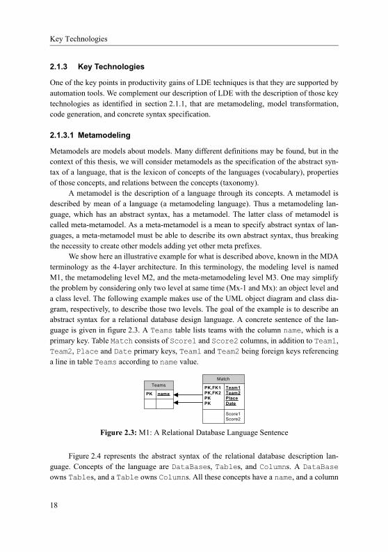
We show here an illustrative example for what is described above, known in the MDA terminology as the 4-layer architecture. In this terminology, the modeling level is named M1, the metamodeling level M2, and the meta-metamodeling level M3. One may simplify the problem by considering only two level at same time (Mx-1 and Mx): an object level and a class level. The following example makes use of the UML object diagram and class dia-gram, respectively, to describe those two levels. The goal of the example is to describe an abstract syntax for a relational database design language. A concrete sentence of the lan-guage is given in figure 2.3. A Teams table lists teams with the column name, which is a primary key. Table Match consists of Score1 and Score2 columns, in addition to Team1, Team2, Place and Date primary keys, Team1 and Team2 being foreign keys referencing a line in table Teams according to name value.
Figure 2.4 represents the abstract syntax of the relational database description lan-guage. Concepts of the language are DataBases, Tables, and Columns. A DataBaseowns Tables, and a Table owns Columns. All these concepts have a name, and a column
Teams
PK name
Match
PK,FK1 Team1PK,FK2 Team2PK PlacePK Date
Score1 Score2
Figure 2.3: M1: A Relational Database Language Sentence
18

Language Driven Engineering
has a type (i.e. text, number, or even column in case of foreign keys). Figure 2.5 shows an
excerpt of the abstract syntax tree for the sentence shown in figure 2.3 as occurrences of concepts of figure 2.4 using the UML object diagram formalism. We can see here that all information may not be explicitly represented in the concrete syntax, following the example of the DataBase name or types of Columns. Experts in metamodeling may have noticed that the M1 abstract syntax graph (ASG) of figure 2.5 is represented as objects conforming to the M2 (meta-)classes defined in figure 2.4.
As said above, to define metamodel as we did in figure 2.4, we used a metamodeling language, and figure 2.6 may be seen as a concrete representation of occurrences of con-cepts of a given metamodeling language with which can be described concepts of meta-class, meta-attribute, etc. This follows exactly the same pattern as before, shifted by an M-number. One such metamodeling language as standardized by the OMG in the context of MDA (see section 2.1.2.2) is MOF [ISO05, ACC+06], a simplified variant of UML class
Table
NamedElement
name : stringname : string
DataBase
A_table_dataBase
table
0..1 *
dataBase Column
isPrimaryKey : boolean
TypedElement
DataType
Element
isPrimaryKey : boolean*
column
A_column_table0..1
table
typedElement
A_type_typedElement
0..1 type
*
Figure 2.4: M2: Relational Database Language Abstract Syntax
dataBase
dataBase
A_table_dataBase
Championship:DataBase
name=Championshipname=Championship
Teams:Table
name=Teams
name:Column
isPrimaryKey=truename=name
Match:Table
name=MatchTeam1:Column
isPrimaryKey=truename=Team1isPrimaryKey=true
name=TeamsisPrimaryKey=truename=nametable column
A_column_table
name=Match
table
table
A_table_dataBase
name=Team1
type
typedElementA_type_typedElement
A_column_table
table column
Figure 2.5: M1 conforming to M2: Figure 2.3 as an ASG (Excerpt)
19

Key Technologies
diagrams. We show in figure 2.7 an excerpt for MOF 1.4 (corresponding to level M3), and in figure 2.6 an excerpt of abstract syntax graph for metamodel (M2) as instances of MOF 1.4. Although not shown here, concepts of M3 may be represented using M3, e.g. MOF
may represent concepts of MOF. As a consequence, there is no need to apply the Mx-1/Mx conformance pattern again and again. In this example, we didn’t show an example for M0, the real world, but it is again the same pattern. One may think of most interesting matches of his/her favorite sport as M0 sentences, which are instances of M1, represented by lines in a relational database formatted as prescribed in figure 2.3.
The success of MOF as a metamodeling language is as broad as it is hard to find a really different approach nowadays. Actually, if one can find alternatives to the 4-layer architecture [Hof79], other tools and researches are subsets and/or extensions to MOF as EMF [Ecl05], Coral [Por03], KerMeta [MFJ05], or XMF-Mosaic [CESW05]. Even meta-modeling tools which neglected abstract syntax before are aligning themselves to the stan-dard, as GenGED [Bar98] which evolved into Tiger [EEHT05]. However, MOF cannot pretend being the historical metamodeling language, and tools may use older modeling lan-guages or even traditional programming language. Two such examples are AToM3 [dLV02], which uses Entity-Relationship diagrams and/or Python, and FAMIX [DMNS97], which introduced a language-independent metamodel that could be indifferently implemented in SmallTalk, C++, Java, or Ada. Still, we stick to the object paradigm as a mean to describe concepts.
If metamodeling languages permit to describe abstract syntax of modeling languages, one need implementations to store models. Politic applied by most approaches (MOF-Based repositories, EMF, AToM3) goes beyond code generation. Actually, those tools generate a
:Class
name=NamedElement
:Class
name=Table
:AssociationEnd
container
name=Table
supertype
Generalizes
type
contents
container
:Class
name=DataBase
:Association
name=A_table_dataBase
:AssociationEnd
name=NamedElement
name=A_table_dataBase
subtype
contents
container
Contents
name=DataBasetype
IsOfType
subtype
supertype
Generalizes
Contents
:Class
name=Element
:Attribute
name=name
String:DataType
name=name
Contents
contents
IsOfTypetype
Generalizes
subtype
name=Elementsupertype
IsOfType
Figure 2.6: M2 conforming to M3: Figure 2.4 as a MOF ASG (Excerpt)
20

Language Driven Engineering
storage artefact for models with a specific API to make it possible to manipulate and/or lis-ten changes in the model, independently from the storage technology. For instance, some tools, like MDR [Sun05], can be configured to target either in-memory hashtables, in-file b-trees, or relational databases, while offering the same data access API. These software com-ponents, together with their accompanying API, are called model repositories. The MOF standard defines precise transformation rules from MOF metamodels to CORBA APIs, which de facto standardizes CORBA-based model repositories. JMI [Jav02] is another stan-dard for transforming MOF metamodels into raw Java APIs, which is in use in numerous tools like MDR. Model repositories are at the core of modeling tools and are most of the time a requirement for using model transformations, if not included in model transformation engines.
Moreover, to exchange models, the OMG issued the XMI standard [ACD+05], which is a way to represent a model in a textual XML file. XMI is flexible enough to comply to any metamodel as soon as this latter is described using MOF. Actually, a metamodel speci-fies an XML schema (DTD or XSD) of XMI representations of conforming models.
Model
Element
Namespace
Generalizable
Element
Feature
Typed
Element
Classifier
Data Type
Behavioural
Feature
Structural
Feature
Import
Package
ClassAssociation
Tag Constraint
ParameterStructure
Field
Constant
ReferenceException
Association
End
AttributeOperation
Structure
Type
Enumeration
Type
Collection
Type
Primitive
Type
/Depends On
Generalizes
Contains
Aliases
Can Raise
Is Of Type
Attaches To
Constrains
Refers To/Exposes
0..*
0..*
0..*
ordered
0..*
*..0*..0
0..*
0..*
1
1..*
0..*
1..*
0..*
0..*
1
0..*
0..*
1
0..*0..*
ordered
ordered
ordered
Alias Type
Figure 2.7: M3: MOF 1.4 (© OMG)
21
Key Technologies
Because this technique is dedicated to tool communication and is rather hardly readable by humans, OMG also issued HUTN [DDF+04], which follows equivalent principles, but using a more human-readable grammar.
For abstract syntax to be rendered as precisely as possible, metamodeling standards and tools often propose to complement metamodels with constraints. Constraints may be expressed using in any sort of language capable to query a model, for instance Java code that uses JMI interfaces, or Python in the case of AToM3. MDA proposes OCL [ABF+06], a side-effect free language dedicated to navigate class-based models, regardless they are MOF metamodels or UML class diagrams (see section 2.1.2.5).
2.1.3.2 Model Transformation
Model transformation is the second important technique to LDE as underlined in section 2.1.1 and in [SK03]. Many survey of model transformation techniques and stan-dards are available, for instance in [CH06].
Model transformations make it possible to build bridges between modeling languages for dedicated purposes. They may be compared to compilers in traditional language engi-neering as they can translate models of a certain metamodel into models of other metamod-els, for example transforming a class model into a relational model [MFV+05]. However, their usage is much broader as they can cover a full exploration and manipulation of mod-els. For instance, one may compute metrics about models (e.g. in [VBBJ06]), perform model refactoring (e.g. in [MB05]), or precise models according to a platform (e.g. section A.2 on page 134).
Regarding model transformation, different approaches may be taken. First, as models may be represented by XML files, many used the XML transformation language XSL. If this was a solution at the early times of model transformation, its has shown neither to be scalable nor agile from a software engineering point of view. Another way to transform models are transformation languages which are dedicated to a given metamodel, following the example of J from Objecteering that is dedicated to UML model transformation. If they particularly fit to transform a certain type of model, since one may not need to know the underlying metamodel to write a transformation, they cannot be applied to other metamod-els and are thus not general solutions to model transformation. A third way to transform models is to take advantage of model repositories as described in previous section: as a model repository proposes an API for model manipulation, one may use a general language (e.g. Java or Python) to access the API and thus manipulate models. Last technique is to use a general purpose transformation language, i.e. a DSL whose domain is model transforma-tion.
Regarding that last possibility, OMG is establishing the Query/View/Transformation (QVT) standard [CCD+06]. Actually, QVT proposes various solutions to transformation. It proposes compatibility standard to make use of non-QVT transformations, it proposes two
22

Language Driven Engineering
declarative languages based on pattern matching as inspired from graph grammars (see section 2.2.2.1), and an imperative language. Moreover, an impressive number of languages and associated tools appeared those last years. Examples are ATL [BDJ+03], the Borland Together tool [Fon06], MTL [fRiCSI05, VJ04], MOLA [KBC04], and BOTL [BM03].
Another way to transform models has been proposed. One of the KerMerta’s metalan-guage goal is to add executability into metamodels [MFJ05]; as a side effect Kermeta is able to transform models whose metamodel is defined using KerMeta [Fle06, MFV+05].
2.1.3.3 Code Generators
Resulting artefacts of the application of an LDE process are models. However, models are rarely usable as is and there is often a need for a translation to artefacts that are directly understandable by execution platforms. An example of such artefact is program code, which can be compiled into an executable file. To do so, there exist several code generators from models.
Apart from modeling tools dedicated to only one sort of model, and featuring a spe-cific code generator wired to a certain platform, most code generators has applied a tem-plate-based generation. This technique makes it possible to specify, for each metaclass, some text in which are interleaved queries to the model (repository). One may compare such technique with dynamic web applications, written in scripting languages as JSP or ASP, which are HTML templates in which are interleaved queries to a database. Examples of tools that apply such template-based technique, and which are taking advantage of the Apache Velocity template engine, are Fujaba [GSR05], and AndroMDA [Boh07] that both offer an evolved template management (through cartridges). Other examples of tools offer-ing a specific template syntax are Acceleo [Obe07], XMF-Mosaic [CESW05], and openAr-chitectureWare [Voe06]. OMG, in the context of MDA, is studying the MOF2Text standard to code generation [CIM+06] that is also based on text templates interleaving instructions and OCL expressions. Even though MOF2Text Request for Proposal proposed bidirectional specification (from model to text and back again), its current status allows only one way generation (from model to text).
Parallax [SS05] is a code generator dedicated to UML models. Parallax offers an interesting management of platform specificities (crosscutting concerns). Actually, a code generator is a simple program that builds an abstract syntax tree of the target language (e.g. Java). Nevertheless, when the model has to be adapted to a specific needs (e.g. distribution), for instance thanks to a profile, code generation facility needs to be reconsidered to deal with that new profile. Parallax promotes the usage of aspects [KLM+97] to modify the gen-eration process. To solve that kind of problem, openArchitectureWare [Voe06] also offers an aspect-oriented mechanism to adapt code generation, but this time directly at template level.
23

Key Technologies
Problem with code generation is that tools tend to integrate platform specification within the generation, for instance a generator that transforms a UML model into an Java EJB application. We believe that it is not an agile approach because one need to deal with two different concerns at same time. On one hand, one need to consider how concepts of the source language (e.g. the UML metamodel) should be mapped into concepts of the target language (e.g. the Java metamodel). On the other hand, one need to deal with concrete syn-tax of the target language (the Java textual grammar). A better approach could be to make an additional model transformation and then a code generation. In this case, model transfor-mation works at concepts level, and code generation does not crosses anymore the language boundaries. For instance, one may better propose a model transformation to distribute his/her UML model, then a transformation to an EJB model, and finally a code generation to Java/EJB. Going one step further with this philosophy, one may regret the lack of bidirec-tional code generation. Indeed, if one introduces metamodels for common languages (as Netbeans did for Java [Net05]), it may be interesting to be able to generate code out of the model, but also to get the model from some source text.
2.1.3.4 Graphical Concrete Syntax
To define a language in general, and a modeling language in particular, one need to specify concepts (i.e. abstract syntax, that is metamodel in the case of modeling languages), seman-tics, and concrete syntax. A concrete syntax is a surface language that acts as an interface between the instances of the concepts, and the human being supposed to produce or read them. Concrete syntax may be textual or graphical, but is often a mix of both.
Up to a recent time, graphical concrete syntax was hand coded in diagram editors using two-dimensional drawing libraries such as Swing or GME. Problem with this approach was that it was hard to read for humans, and that it was also long to develop and maintain.
Most solutions to graphical concrete syntax definition on top of a metamodel are based on ad-hoc symbol editors, following the examples of AToM3 [dLV02], GME [Dav03], or MetaEdit [Poh03]. For each representable element of the metamodel, one defines an icon and indicates properties to be displayed. Such tools make a clear distinction between entities and relations, thus making possible to design only a nodes-and-bounds type of graph, so called connection based language (see section 2.2.2).
Other solutions propose to map the abstract syntax to a graphical language described as a metamodel, as proposed in [DV02]. For instance, XMF-Mosaic [CESW05] proposes to write a bidirectional transformation to a metamodel which has a graphical representation semantics, with squares, lines, etc. A similar approach does not require a model transforma-tion, but rather models that capture information regarding abstract syntax representation metamodel mapping (see figure 1.1 on page 5). Topcased [VPF+06], or GMF [Ecl06] are
24

Language Driven Engineering
such tools, so does Tiger [EEHT05] even though representation metamodel is not explicit. Still, all these solutions stick to connection based graphical languages.
When it come to concrete modeling, concepts are manipulated by mean of their repre-sentation. To do so, one needs to define how icons can be manipulated. As we will discuss in more details in section 2.2.2, graphical models, in contrary to textual specifications, are built interactively by the modeler who sends events to the modeling tool, e.g. to create a modeling element, or to move it. Actually, numerous DSL tools, based on concrete syntax description, offer standard behavior to defined representations (e.g. to create, delete, move, or connect icons). Other approaches take advantage of graph grammars to describe such behaviors [BGdL06], following the example of Tiger or AToM3.
One should not confuse graphical concrete syntax specification with diagram inter-change, as XMI-DI [ADG+06], which is a standard of the OMG. XMI-DI enters the cate-gory of Representation Data as shown in figure 1.1 on page 5. If graphical concrete syntax deals with concrete representations of concepts given by a metamodel, diagram interchange is only a mean to store graphical information of a diagram. Actually, diagram interchange is not a mean to describe how abstract and concrete syntax relate. On the con-trary, it is a mean to tell, for a given model, which elements of the abstract syntax tree are represented, and what are the chosen variations in the representation (e.g. place, size, color, provided that information is not reflected in the abstract syntax graph). To summarize, if concrete syntax makes explicit all possible representations for a given concept, diagram interchange makes explicit what is the chosen variant in representation for rendering con-cept instances.
Regarding textual concrete syntax, current solutions mix code generation with manual text parsing, both of them having to be consistent, even though some tools may help in pars-ing texts to create models [HRS02, CESW05]. We do not consider automatic syntax gener-ation, as in MOF2Text or [AP04, GRS06] since concrete syntax must follow specific rules in its form. We are only aware of TCS [JBK06] that recently offered a comparable approach to the one we will describe in chapter 4 and that we studied in [FSGM06] and in [MFF+06].
2.2 Traditional Concrete Syntax Engineering
This thesis attempts to give some preliminary answers to concrete syntax definition for modeling languages, answers that will be inspired by solutions outside the LDE community. Textual and graphical definition of concrete syntax are technical spaces by themselves and deserve to be introduced in section 2.2.1 and section 2.2.2. We also introduce in section 2.2.3 the SVG standard, which will be the basis for a solution to graphical concrete syntax specification.
25

Traditional Textual Language Engineering
2.2.1 Traditional Textual Language Engineering
Compiler construction was one of the very first way abstraction appeared in computer sci-ence: in early 60s, it was a revolutionary idea to make an automatic translation from a "computer scientist readable" textual specification to computer understandable binary code. Productivity gains triggered by simplifying the program specification led to extensive research on finding the best possible abstraction for programming a computer (Algol, For-tran, C, etc.). Compiler construction techniques evolved as the number of experimented lan-guages increased.
Among the most interesting results of compiler construction experience are genera-tive grammars [Cho56], attributed grammars [Knu68], and Backus Naur form (BNF) [BBG+60], improved by the Extended BNF (EBNF) [Int01], which are all able to describe structured texts. Those results are used in compiler compilers, i.e. compilers that take as input an EBNF-like grammar, and which generates a program able to analyze a text con-forming to that grammar. Such compiler compilers are Lex/Yacc [Joh79], or ANTLR [PQ95], and nowadays their success is as universal as that they are taught in universities.
Their general principles are the following. First, one should describe so called termi-nal symbols, such as numbers, comments, keywords, etc., in a lexer grammar. From this grammar, the compiler compiler generates a lexer, that is a program which takes as input a text and transforms it into a string of such defined symbols (tokens) - this phase is called the lexical analysis. A token is associated to its type (Number, Comment, Keyword, etc.), a text (e.g. "12.85" for a Number), and eventually a location (e.g. a line and a column). As a second step, a parser should be defined usually in the form of EBNF-like rules (an expression is either an addition, or a subtraction; an addition is a Number ter-minal, a terminal +, and another Number terminal). Again, the compiler compiler generates a program. This latter program, the parser, takes as input the token stream obtained from the lexer and analyses it according to the grammar - this phase is called syntactic analysis. The outcome is a concrete syntax tree that organizes the tokens into a hierarchy following the order of triggered rules. Most of the time, actions can be embedded in the parser rules so that one may build an abstract syntax tree that may be later walked through to generate code (e.g. if parser analyses an addition, it should build an addition object and associate the cor-responding operands as analyzed from terminal numbers). Unfortunately, abstract syntax tree construction (semantic analysis) and code generation are poorly automated tasks and should be programed using general purpose languages.
Parsers may be classified in two categories. Top-down parsers (LL parsers - from Left to right using Leftmost derivation) attempt to trigger the topmost rule (the main rule), and move down into grammar rules. For instance, if expression is the topmost rule, an LL parser will trigger the rule and then choose among the alternatives. On the contrary, bottom-up parsers (LR parsers - from Left to right using Rightmost derivation), also known as shift-reduce parsers, will store tokens into a stack up to a rule is matched. For instance, it is only
26
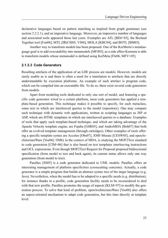
Language Driven Engineering
when the token stack contains a Number, a +, then another Number, that the additionrule then the expression rule will be recognized.
Parsers usually drive their associated lexer, that is, they consume token at same time they analyze rules. This raises an important drawback in that some rules may be conflicting. For instance, at the moment an LL parser consumes a Number terminal, it cannot decide whether the triggered rule should be addition or subtraction. To solve that problem, two pol-itics are possible. Lookahead parsers can analyze more than one token at a given moment. In the operation example, the parser can decide between addition and subtraction looking at the next token, that should be either a + or a - terminal. Depending on the grammar com-plexity, that number k of token to be accessible in advance is different, but the more impor-tant that number is, the more complex and the less efficient the parser is. The parser is said to be LL(k) or LR(k). An usual value for k for common programming languages is 3. Back-tracking provides a second solution to the conflicting rule problem. Actually, in case of con-flicting rules, such parser chooses an alternative and continue analysis "hoping" the right alternative was chosen. In case an analysis fails, the parser goes back to its last choice and takes another alternative. For instance, such parser will chose the addition rule each time it will encounter a Number terminal. If the next token is a - terminal, the addition rule fails, and the parser backtracks to state at the time of the choice and starts again analysis using the subtraction rule alternative. Note that both lookahead and backtrack technolo-gies are compatible.
A thorough description of compiler construction may be found in [ALSU06].
2.2.2 Graphical Language Engineering
Almost each of today’s modeling languages comes with a graphical representation in order to improve readability and usability. Thus, the concrete syntax of modeling languages should be defined in terms of a visual language. For this reason, we summarize here the rel-evant basic terms from visual language theory.
A visual language describes a set of visual sentences which in turn are given by a set of visual elements. A visual element can be seen as an object characterized by values of some attributes. It depends from the language which attributes are important for a graphical element1, some of the most frequently used attributes are shape, color, size, position, attach regions. We will further refer to such data as representation data in the rest of the disserta-tion.
Visual elements are arranged in the two- or higher-dimensional space. For some lan-guages (which are classified in [CLOP02] as geometric-based languages) the position of visual elements is an important information, e.g. a sentence consisting of a circle and a
1. There is a common classification of attributes into graphical, syntactical and semantic attributes. Only the first two classes of attributes are relevant for our approach because semantic attributes are already captured by the abstract syntax definition.
27

Graphical Language Engineering
square where the circle is placed at point (1,0) and the square is placed at (2,0) is another sentence than the sentence where the square is placed at (1.0) and the circle is placed at (2,0). However, for real-world languages, the absolute coordinates are much less important than the spatial relationships between graphical objects. Some of the most frequently used spatial relationships are RIGHT, UP, CONTAIN, OVERLAP (see [CLOP02] for a more com-plete list). It heavily depends on the visual language which of the spatial relationships are considered to be important. An example is the chessboard language as introduced in section 5.2.2 on page 87. Sometimes, languages are geometric-based even if it seems that the visual elements can be arranged freely. One example is the language of UML class dia-grams. At a first glance, rectangles for classes can be placed freely at any point in the space. For instance, a diagram consisting of two rectangles labeled with A and B would always be read as the same sentence no matter where the (rectangles for) class A and B are placed. However, there is one exception from this rule: If - let’s say - the rectangle for B appears completely inside the rectangle for A, then the class A is read to be composed of class B. Thus, the spatial relation CONTAIN is important to define the visual representation of class diagrams whereas the relations RIGHT, UP, etc. do not play any role here.
In addition to geometric-based languages, there is another group of languages called connection-based languages. This languages allow the visual elements to be completely freely placed in the space and, thus, none of the spatial relationships is important when a sentence of such languages has to be read. Instead, it is an important information whether two elements are connected by a connector (usually a line, polyline, curved line) or not. Connectors start and end in special regions of visual elements, so called attach regions. A visual object can have one or more attach regions which can sometimes collapse to attach points. As already mentioned, visual language definitions formalize the attach regions of an visual element just as attributes of it. This abstracts from the problem to define where an attach region is exactly located in respect of the visual element (e.g. in the lower right cor-ner). However, there are symbol editors available, e.g. as part of VLDESK [CDP04] or AToM3 [dLV02], that allow to exactly define attach regions for a visual element as well as to solve the very similar problem of defining a shape for it. In fact, most real-world visual languages show characteristics of both geometric-based and connection-based languages and are thus called hybrid languages.
To summarize, a visual sentence is given by a set of visual elements together with their values of (language dependent) attributes and information on holding (language dependent) relationships between them. The definition of a visual language might restrict the possible relationships between elements and, for instance, say that the rectangles repre-senting a class A must contain the rectangles for all classes A is composed of.
Finally, visual elements can completely hide other elements. Thus, by looking on the visual sentence, it is impossible to distinguish between the visual sentence containing the hidden element from a sentence where the hidden element is dropped. This problem can easily be fixed by introducing in the language definition a spatial relation HIDDEN_BY and
28

Language Driven Engineering
adding a constraint, that visual elements should never hide completely another visual ele-ment.
2.2.2.1 Graph Grammars
As explained above, a diagram, i.e. a visual sentence, is a set of parametrized component instances, together with spatial relationships (RIGHT, UP, CONTAIN, OVERLAP). Thus, a diagram may be seen as a directed graph and may be defined and transformed using graph grammars.
Graph grammars [Nag76, Göt82, EEKR99] (and graph transformations) are construc-tive approaches to graph evolution based on pattern matching and have its roots in textual language engineering (see section 2.2.1), and was source of inspiration for QVT (see section 2.1.3.2). A graph grammar is a collection of production rules. Production rules, which may be attributed, are composed of a left-hand side, which provides a pattern to match (i.e. search criterion) in the graph, and a right-hand side, which describes the modifi-cations to apply to the matching region.
Graph grammars are able to define formally visual languages [Min02]. The same technique may apply to define how to construct a valid language sentence (i.e to add a new element to a diagram) and to define what is the semantics of the language (i.e. to make a system state evolve according to a language sentence) [And96]. To make the sentence evolve corresponds to triggering one of the rule in the graph grammar: a user interaction, like adding a new element, connecting elements together, renaming an element, changing colors, etc., actually correspond to a production rule triggering. The interested reader may find an introduction and some examples of visual language definition in [Jon90]. Moreover, some tools implement those ideas as GenGED [Bar98] and AToM3 [dLV02].
Triple graph grammars [Sch94] are an extension of graph grammars to keep consis-tent manipulated data. Production rules contain intermediate rules, the correspondence pro-duction, that relates left to right hand sides. This allows to maintain correspondence data that are necessary to keep source and target model consistent according to the grammar when one of the two model changes. Unlike simple graph grammars, triple graph grammar allows one to separate clearly abstract syntax from concrete syntax: the grammar states how the abstract syntax tree may be represented by the concrete syntax tree; if the concrete (respectively abstract) syntax tree is changed, the abstract (respectively concrete) syntax tree is automatically changed accordingly.
2.2.3 Scalable Vector Graphics
Scalable Vector Graphics (SVG) [JN05] is the only open standard for describing two-dimensional vector graphics. SVG is not related to a platform, thus it can be in use on plat-forms as various as computers (regardless of the operating system) or mobile devices. The scope of standard is very broad makes it possible to draw basic shapes (circles, rectangles,
29

Conclusions
Bézier curves, etc.), to integrate and mix raster images, etc., with a large number of possible customizations (e.g. animation and transparency).
One of the most important characteristic is that SVG is an XML [BPSM+06] dialect. The eXtensible Markup Language (XML) is another open standard for structured data inter-change based on text files. As a consequence, as any XML specification, SVG may be manipulated by the Document Object Model API (DOM) [HHW+04]. The DOM API allows to access and alter XML data using languages (like Java) or scripts (like JavaScript). This means that a script or a program may manipulate an SVG document that an SVG inter-preter will be in charge of rendering dynamically.
DoPIDOM [Bea06] is a framework for developing DOM-based components able to manipulate an SVG document at same time the SVG document is rendered. It is based on Batik [Apa], and organizes DOM components in two categories: query consumer for navi-gating the SVG document and action producer for altering the SVG document.
2.3 Conclusions
LDE is a set of model-based techniques to software development. Main artefacts of a soft-ware development process are models, not only used for documentation purposes, but also as development artifacts. The process is stepwise, each step consisting in adapting result of the previous step (a model) with details of the deployment on execution platforms, follow-ing the examples of RUP [Kru03] and B [Abr96]. Input and output models are described by metamodels, which represent the abstract syntax of the modeling language, and are related by model transformations, which help in the improvement. First step is to describe the desired system into a model, and last step consists in generating code to be deployed in an execution platform. Beside clear advantage of the improvement process (e.g. adaptation to changes, traceability, etc.), the LDE model-based approach promotes to use the right (mod-eling) language for the right purpose, thus avoiding to use a too large or inappropriate lan-guage, without that necessity to stick to only one general purpose language for the whole process.
Thus, to define such a model-based process, methodologists need to clearly specify those languages, and developers need to correctly understand them. Moreover, to scale, such approach must be supported by comprehensive modeling tools. Drawback is that those tools require a lot of energy in development, and are only designed for a limited community.
To correctly specify a language, one need to define its abstract syntax, its semantics, and its concrete syntax. Abstract syntax may be given by mean of a metamodel, which allows to build model repositories (responsible for model interchange), which are the pillars for those bridges that are model transformations. Some solutions for semantics are already around (e.g. using set theory, or model transformations), though intensive research is still on
30
Language Driven Engineering
the way [HR04]. However, we found that concrete syntax definition still lacks maturity in the LDE community.
Regarding graphical concrete syntax, techniques and tools are already around, as graph grammars. Some has even ported results of this technological space to the LDE com-munity (e.g. [EEHT05]). Moreover, model-based technology evolved rapidly last years (especially since the start of this thesis). Nevertheless, we feel that these solutions, if they at nice at tooling, still lacks universality and are too imperative to serve as specifications.
Regarding textual concrete syntax, the situation is rather worse and has not gained the attention it deserves. Indeed, one need to specify consistent code generation and text pro-cessors using poorly specialized tools. However, there exist solutions in another technologi-cal space, namely compiler compilers, that may help in finding a comprehensive specification to concrete syntax.
In this thesis, we propose solutions for graphical and textual concrete syntaxes that we feel could be used as specifications.
In next chapter, we continue our presentation of LDE with an example of an LDE pro-cess definition and application. Another example is given in section A.2 on page 134. [NWHR06]
31
Conclusions
32

Netsilon: LDE Example and Embryonic Solution
Chapter 3:
Netsilon: LDE Example and Embryonic Solution
Netsilon is a web application modeler and generator. Construction of the tool has followed the LDE principles to support an LDE methodology for web application engineering. In addition to reusing a subset of UML, it integrates notably two new DSLs, one graphical (the Hypertext Model) and another one textual (Xion). We developed Netsilon in a small com-pany, ObjeXion Software, between 2001 and 2002, using technologies of that time: model repositories are hand-coded using the java language and model transformations are java programs. After introducing general remarks about web applications in section 3.1, we give general principles of Netsilon in section 3.2 and implementation insights in section 3.3 as an example for language engineering. We also show that Netsilon may be seen as a generic code generator able to produce some text from a model. An example, developed in section 3.4, shows generation of text following rules of the SVG language to graphically depict a simple class diagram model. However, Netsilon cannot be seen as a complete solu-tion as it is specialized in generating text representations: it is not possible to reverse the process (from text to model), and graphical syntaxes are not natively handled. Nevertheless, experience presented here is at the root of solutions developed in next chapters.
Section 3.1, 3.2 and 3.3 of this chapter are inspired from [MSFB05]as published in the journal of Software and System Modeling (SoSyM) in 2005.
3.1 Web Applications
A web application is an information system which supports user-interaction through web based interfaces. Typical web applications feature data persistence, transaction support and dynamic web page composition.
A web application is split into a client-side part, which is running in a web browser, and a server-side part, which is running on a web server. The client-side is responsible for page rendering while the server-side is responsible for business process execution and web page construction. The process of page construction varies widely in dynamicity, ranging from completely static, in the case of predefined web pages, to totally dynamically con-structed pages (which vary in terms of content, presentation and navigation), when the web pages are the result of some computation on the server: programs (that can be written in lan-guages like PHP, JSP, Java, or ASP .NET) integrate into web pages the graphic elements
33

LDE for Web Application Engineering
and the information coming from many kinds of data sources (like databases, files, sessions or context variables…).
3.2 LDE for Web Application Engineering
Netsilon is a web application modeler independent from deployment platforms: one can describe a complete dynamic web application at the analysis level without integrating any detail depending on the application server or the database server. The architecture of Netsi-lon is given in figure 3.1.
Once the requirements have been gathered (via techniques such as use-cases and activity diagrams), the web application is modeled from three points of view, the Business Model, the Hypertext Model, and the Presentation Model. These models are independent from the web platform (i.e. application server and data persistency technique); they capture a comprehensive description of the web application. With the help of Xion, an action lan-guage designed to query and manipulate the business model, they contain enough informa-tion to drive the generation of the final web application. In addition to these three models, a Deployment Model gives information about the target platform, i.e. the kind of application server (PHP, JSP or Java), the kind of data repository (relational database), and information like the URL of the web application, or password to access database. Models and their rela-tions are given in figure 3.2.
Figure 3.1: Web Application Modeling with Netsilon
Web Server
BusinessModel
Compositionand
NavigationModel
PresentationModel
BusinessObjects Scripts
Templates
UMLMetamodel
HypertextMetamodel
PresentationMetamodel
WebBrowser
1: Request
3: Answer
2: ProcessingGlue
34

Netsilon: LDE Example and Embryonic Solution
We continue the section by describing in more details the business model, the hyper-text model and the presentation model. We also present the Xion action language.
3.2.1 Business Model
The business model describes the organization of the business concepts managed by the web application. UML class diagrams are used to represent business classes, their attributes, operations and relations. The implementation of methods is specified with the action lan-guage Xion.
The business model is used as an input of the model-driven process which generates the business layer of the web application, using guidelines described in the literature [MVC03]. Object persistence is provided by a relational database, whose schema is derived from the business model. The object-to-relational mapping is designed so that incremental modifications to the business model have as little impact as possible on existing information in the database; we talk of M0 preserving transformations. The relational database is com-pletely abstracted away. The business model is a subset of UML class diagrams in that it does not integrate multiple inheritance, n-ary associations, or derived attributes. Concrete syntax is that one of UML class diagrams. The classes from the business model are all per-sistent by default, the code is completely generated.
The advantage is that the designer does not have to care about persistence, the process of creating and updating the database schema is completely automated, and implementation classes for the business model are generated in the web platform target language (either Java or PHP).
An example of business model is shown in figure 3.3. Designed web application is a simple genealogy store. Persons may be married and have two parents. Operation Per-son:marry is implemented in Xion and creates the corresponding Marriage object, if gender is actually different between the people to marry.
Figure 3.2: Netsilon Set of Models
Business Model Hypertext Model Presentation Model
XionDeployment Model
ObjectAdministrator
Generator
35

Hypertext Model
Netsilon features an Object Administrator generator. The object administrator is a generic web application for the purpose of administrating the objects stored in the database. Data are organized in objects according to the business model, and objects can be created and deleted, their attributes can be updated, links can be created between objects, and oper-ations can be executed. This administration tool is very helpful, and is used both for initial-ization of the object database and for data maintenance purposes. The generator is actually a model transformation that creates a specific presentation and hypertext model from the business model. Such derivation is achievable since the user interface of the object adminis-trator does not have to be customized, and can therefore follow simple user interaction pat-terns.
3.2.2 Hypertext Model
The second model, the hypertext model, is an abstract description of composition and navi-gation between document elements and fragments of document elements. In the context of web modeling this model describes how web pages are built (composition) and linked (nav-igation). Hypertext model makes use of a completely new graphical language.
Composition describes the way the various web pages are composed from other pages (fragments) as well as the inclusion of information coming from the business model or cur-rent context (like sessions). Again, Xion is used as a query language to extract information from the business model and as a constraint language to express the various rules, which govern page composition.
Navigation details the hyperlink between the web pages, including the specification of the parameters that will be transferred from page to page, as well as the ability to specify actions to be applied when triggering a link (typically to execute a method defined in the business model). The Xion language allows the specification of the actions to be performed when transitioning from one page to another and the declaration of predicates that lead to the selection of a particular path between pages according to the current context and the business model.
Person
public String namepublic String surnamepublic Gender genderpublic PersonStatus status
public Marriage marry(Person person)Marriage
public Date date
Gender
public String malepublic String female
<<enumeration>>
0..*
children
2
parents
0..1
husband
0..1
wife
Figure 3.3: An Example of Business Model
36

Graphical Concrete Syntax
This simple example already reveals some of the weaknesses of informal concrete syntax definitions. The definition given figure 5.2 is incomplete because, for example, it was not stated yet that an event should be shown nearby the transition it triggers. Moreover, the name of a simple state should be contained in the representation. The same problem appears for the composite state: the name should be contained in the upper part of the com-posite state icon, the lower part being reserved for the composite state contents, that is the representations of its sub-states. A transition representation (an arrow) has to go from the representation of the transition’s source to the representation of its target. Some symbols contain parameters (as event in Transition) as placeholders for additional information. It is, however, not specified yet where the information comes from, e.g. that the event attached to a transition is indeed that event that triggers the transition. Another problem is that there may be different icons for the same concepts, as for the PseudoState. Again, the choice, which in this particular case depends on the PseudoState kind, is not captured by the figures. It can also be the case that one icon may present some variants in its representation. For instance, it may be possible to represent a composite state without its name part, or without its contents part.
5.2.2 Chessboard
We define in figure 5.4 metamodel for a very simple language whose sentences are all pos-sible positions of pieces on chess boards. A situation refers to a board, so we introduce the metaclass Board to represent the board concept. This board consists in 64 squares, so we introduce a metaclass Square and an association forcing each Board model element to be
Piecekind : PieceKindcolor : Color
64 32
1 1
Square
x : Integery : Integercolor() : Color
«enumeration»Color
whiteblack
«enumeration»PieceKind
pawnrookknightbishopqueenking
Board
0..10..1 PieceResidencecontext Square inv:
1 <= self.x and self.x <= 8 and 1 <= self.y and self.y <= 8)
context Board inv: self.square->forAll(sq1,sq2:Square|
(sq1.x = sq2.x and sq1.y = sq2.y) implies sq1 = sq2)
Figure 5.4: The Chessboard Metamodel
87

Chessboard
related to 64 Square model elements. Squares can be identified by their position; this is modeled by the x and y integer meta-attributes. Of course, Square model elements must define values for x and y between 1 and 8; that can be modeled with a constraint written in OCL. Moreover, two squares of the same board must not have the same position. Again, this can be stated by a constraint. Squares are also qualified by a color (black or white) that can be computed from their position; this can be represented using a meta-operation. The board also consists in 32 pieces, of a given color, and of different kinds: pawn, rook, knight, bishop, queen, and king; this can be modeled in a same way by introducing a Piece metaclass with a color and a kind attribute, together with an association. More-over, if not captured, a piece resides on a square, thus preventing any other piece to occupy this square, as could be shown by a PieceResidence meta-association. If captured, a piece is aside and does not reside on any square. Some additional constraints should be defined to state the kind of pieces that have to be part of the game (16 pawns, 4 rooks, 2 queens, etc.), but they have been omitted for sake of brevity. Of course, the presented abstract syntax is not at all the unique possible one for the chess board language. For instance, one could prefer avoiding the Square metaclass and directly assigning the posi-tion to pieces.
Figure 5.5 is an attempt to provide a conforming model. It presents a Board model element, related to two Square model elements and one Piece model element. Each square is related to the piece by the mean of two links of the PieceResidence type. How-ever, that model does not conform to the chessboard metamodel for three different reasons. First, the metamodel states that a Board model element must be related to 32 different Piece model elements and 64 Square model elements. In this case, the board is only con-nected with one piece and two squares. Second, a piece is located on two different squares, which is not allowed by the PieceResidence meta-association 0..1 multiplicities: a piece must be located at most on only one square. Third, the two square abstract representa-tions have the same position as indicated by the values they provide for the x and y meta-attributes, thus violating the constraint depicted in figure 5.4.
:Squarex = 1y = 8
:Piecekind = #rookcolor = #black
:Board
:Squarex = 1y = 8
:PieceResidence:PieceResidence
Figure 5.5: An Incorrect Chessboard Model
88

Graphical Concrete Syntax
Figure 5.6, on the contrary, depicts a correct chessboard sentence representation, but this time using the chessboard concrete syntax instead of raw instances of the metamodel given as object diagrams. An informal version of chessboard concrete syntax should illus-trate the gap between the abstract and concrete syntax. Such a definition could state that (1) the board is displayed by the two, orthogonal x and y axes annotated with 1..8 and a..f, (2) the squares are represented by a white or gray square depending on the (derived) attribute color of the model element at a position between the two axes of the board according to the values of the x and y attributes; the size of the squares corresponds to the size of the board, and (3) the pieces that are not captured yet are shown at the corresponding squares by a fig-ure of well-known shapes.
Note, that in the particular case of the chess board language the concrete syntax basi-cally fixes the visual appearance of a sentence, i.e. an instance of the metamodel. Once the position and size of the board is fixed, the position of all other visual objects are determined and there is no alternative way to draw the sentence.
5.3 Concrete Syntax Specification
As shown by the statechart sentence in figure 5.3, each sentence of a language can be repre-sented as an object diagram conforming to the language’s metamodel. While language defi-nitions given in form of a metamodel are easy to read and to understand, the sentences of the language are not accessible by humans if given in form of object diagrams. This section will solve the problem of defining a concrete syntax contract, i.e. a more human-friendly
Figure 5.6: A Chessboard Sentence
89

Scheme-based Definition of Concrete Syntax
representation for the sentences of a visual language. Missing information, as pointed in section 5.2, will be added, so that the representation will be defined in a non-ambiguous way what dramatically improves the language’s usability. For example, the concrete syntax contract definition for the statechart notation must allow representations as shown in the right part of figure 5.3 instead of raw instances of the metamodel given as object diagrams shown at the left of the figure.
It is worth to stress that our aim is different from the complete definition of a visual language that is often tackled by graph grammars. Our approach does not aim in defining a visual language from scratch but assumes that the abstract syntax of the language is already given.
Some languages intentionally allow different representations of the same sentence. Hence, we do not aim to define an algorithm able to display a sentence which is given as an instance of the abstract syntax in a more understandable, visual form. Our approach rather goes the opposite direction and allows to decide whether a given diagram is a correct repre-sentation of a given object diagram or not. Thus, our approach sees the concrete syntax con-tract as a specification how sentences can be displayed. The concrete syntax contract definition will be based on the same principles as well-known abstract syntax definitions given in form of metamodels and will yield an algorithm to decide the correctness of a rep-resentation of a sentence. That is why this definition can be considered as a contract to be fulfilled by an representation tool, regardless its technology.
5.3.1 Scheme-based Definition of Concrete Syntax
The definition of a concrete syntax contract means to define (1) a visual language, i.e. visual elements with relevant attributes and relationships between them and (2) how the visual ele-ments are connected to the concepts of the language they are supposed to represent. Figure 5.7 gives an overview how both goals are basically achieved by our approach.
As stated before, language is given by its abstract and concrete syntax (for sake of simplicity, we forget here about semantics). Abstract syntax is defined in terms of meta-model and a language sentence abstract syntax graph is a model conforming to that meta-model. Concrete syntax is another metamodel with two different parts: display classes and display manager classes. The display classes are in charge of concrete representation by stating what are graphical elements to be displayed, and can also declare relevant attribute of their objects such as shape, color, size, position, attach regions, etc. For sake of reusabil-ity, the display classes do not depend on the metamodel; display manager classes are in charge of putting them in relation. Concrete syntax graph of a sentence is given by a set of display objects, each being an instance of a display class, and a set of display managers as instances of display manager classes.
The formalism to define display classes is intentionally left open in the specification step, and should be introduced only in the realization step. However, as we will see later,
90

Graphical Concrete Syntax
display classes are supposed to implement some operations corresponding to (spatial) rela-tionships such as CONTAIN, OVERLAP, etc. We propose in section 5.4 an implementation based on SVG and DOM components. In other words, display classes are merely specifica-tions of what the realization step is supposed to provide as a service. This approach is equiv-alent to defining interfaces (specification) that are further realized by components (realization).
Mapping between visual objects and model elements is formulated by display man-ager classes using a constraint mechanism. For each possible representable metaclass there exists a unique display manager class whose purpose is to restrict the way how instances of the metaclass, i.e. model elements, can be displayed. These restrictions are formulated as invariants written in OCL. Display managers are responsible for consistency between the abstract syntax graph (the model elements) and the concrete syntax graph (the display objects): a display object can exist only in the context of a model element.
5.3.2 Statechart Concrete Syntax
We illustrate our approach by formally defining the concrete syntax of the statechart nota-tion whose abstract syntax was given in section 5.2.1.
Prior to giving the formal definition of the concrete syntax, an informal version of it should illustrate the gap between the abstract and concrete syntax, as already introduced in section 5.2:
Problem 1: A text is shown on the top of transitions to explicit the triggering event if it exists;
Problem 2: A text shows the name of a simple state;
Figure 5.7: Scheme Definition Architecture
Language sentence
ConcreteSyntaxTree
Language Definition
Concrete Syntax
DisplayClass
Display ManagerClasses
Metamodel(Abstract Syntax)
DisplayObjectsDisplayManagersModel Elements(Abstract Syntax Graph)
conformsconformsconforms
91

Statechart Concrete Syntax
Transition
SimpleState
PseudoState
TransitionDM
SimpleStateDM
PseudoStateDM
SVGSimpleState
SVGText
SVGPseudoState
...
Constraining Part
MetaClasses(Abstract Syntax)
Display ManagerClasses
Display Classes
1
1
Sta
teS
chem
e
1
me vo
me vo
me vo
1 1
*
«contains»
1
11
1
Tran
sitio
nS
chem
eP
seud
oSta
teS
chem
e
Iconic Part
«Interface»GraphicalObjectcontains()connects()nearby()overlaps()
dm
dm
dm
SVGTransition
SVGArrowEnd
SVGArrowEnd
«connects»1
start
end1
0..1event
name
CompositeState
SVGCompositeState
SVGText
SVGContents
1
Com
posi
teS
tate
Sch
eme me vo
*
«contains»0..1
11
«contains»
dm
name
contents0..1
SVGInitial
SVGChoice
CompositeStateDM
showNameshowContent
SVGLine«contains»0..1
separator
SVGTexttext:String
«connects»
«nearby»
Figure 5.8: Statechart Schemes
92

Graphical Concrete Syntax
Problem 3: To depict a composite state, depending on the viewer’s choice, either a text shows the name of the composite state, or a region shows the contents of the com-posite state (i.e. its contained states), or both; in the latter case, the two regions are separated by a line;
Problem 4: The plain side of the transition icon is connected to a representation of its source state; the arrow side is connected to a representation of its target state;
Problem 5: The shape of a pseudo-state representation depends on its kind.Figure 5.8 shows the architecture of the statechart concrete syntax definition. We have
shown four display schemes related to four graphically representable concepts as defined in the metamodel: Transition, State, CompositeState, and PseudoState. Final-State have been omitted for the sake of brevity. The other concepts are either abstract (as for ModelElement) and thus will be depicted by the scheme of their subclass, or cannot be graphically rendered (as for Event). The case of StateMachine is a bit particular since it can only be represented by a diagram, which is actually being defined by the schemes.
As proposed in section 5.3.1, the schemes are defined using two layers. In one hand, the display classes, are contracts for the visualization tool/language. The main purpose of this layer is graphical rendering, i.e. iconic definition. In the other hand, the display man-ager classes fill the gap between those display classes and the abstract syntax by connecting them explicitly. A display manager class is connected to exactly one metaclass through an me (for model element) association end; thus, there exist a display manager object for each model element representation.
The cardinality of the opposite association end has also its importance. In the case of figure 5.8, a Transition or a PseudoState model element can only be depicted once, because of the cardinality of the respective dm (for display manager) association ends. On the contrary, a SimpleState or a CompositeState model element may be represented several times with different instances of the display manager class (thus different instances of the display class).
5.3.3 Icon-definition within a Scheme
Besides the association to metaclasses, display manager classes are associated with display classes. For each display manager class there is always a standard association to the corre-sponding display class with multiplicity 1 and role name vo (abbreviation for visual object) on the end of the displayed class. This reflects the fact that each display manager object is connected with exactly one main display object. This connected display object depicts that model element which is connected with the display manager as well. A display class defines through representation data how a model element is actually displayed in terms of shape, color, etc. It also provides some query facilities. Some standard queries (e.g. CONTAIN, OVERLAP), as introduced in section 2.2.2 page 27, are declared by the generic Graphi-
93

Icon-definition within a Scheme
calObject interface. This enforces that any custom display object (like SVGTransi-tion, SVGText, or SVGContents) is capable responding the queries.
Display classes are specifications for the realization step, and do neither depend on the display managers classes, nor on the metaclasses. This enforces a relative independence of the realization language/tool from metamodeling concerns. Indeed, stakeholders con-cerned by graphical rendering are rarely also specialists in language construction. This inde-pendence mechanism is meant to ease the collaboration between domain specialists, whose concern is to describe the concepts of the language, i.e. the metamodel, and the graphical modelers who aim at graphically rendering the display objects. Moreover, this clear separa-tion guarantees that neither concrete syntax architecture pollutes conception of abstract syn-tax nor abstract syntax architecture pollutes concrete syntax conception. It also permits a better reusability of display classes for other concrete syntax.
Often, a model element is not displayed just by one atomic visual object but rather by a composition of such objects. However, all involved objects are arranged by one composi-tion object whose class corresponds to the metaclass it should visualize. Figure 5.9 illus-trates the definitions done in the display classes related to the metaclasses CompositeState and Transition.
The graphical representations for metaclasses CompositeState and Transitionare defined by the classes SVGCompositeState and SVGTransition, respectively. A display object of class SVGCompositeState may compose three objects to display the name of the state (SVGText), the region where the contained states can be arranged (SVG-Contents), and the line separator (SVGLine). Those three graphical elements that take part in the SVGCompositeState display object are composed by the latter with multiplic-ity 0..1. This means that the figure is still valid in the case that some parts are missing for depicting a composite state.
<state name>
SVGCompositeState
name:SVGTextseparator:SVGLine
contents:SVGContents
<event name>
SVGTransitionevent:SVGText
start:SVGArrowEndend:SVGArrowEnd
Figure 5.9: The Composite State and Transition Icons
94
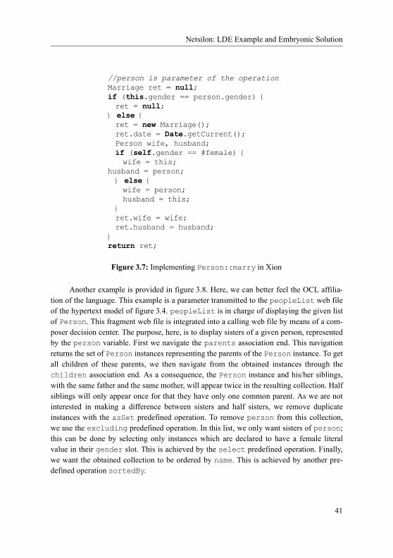
Graphical Concrete Syntax
Similarly, objects of SVGTransition are composed of one object to display the event and two objects representing attach points. The difference is that the composed objects of SVGArrowEnd are mandatory: it is an incorrect sentence of the statechart nota-tion to show a transition with no arrow at the end. SVGPseudoState is a little bit different: there exist many radically different shapes to represent it. Each one of these shapes is repre-sented by a display object (e.g. SVGInitial for an initial state, or SVGChoice for a choice) that inherits from SVGPseudoState. As SVGPseudoState does not represent a figure, it is declared as abstract.
Constraints have well proven their ability to help diagram layout activities [BEdLT04, MMM04]. In our example, there are also some issues in enforcing layout within the figures. For instance, problem 3 stated the conditions under the separator (display object) have to be part of the composite state rendering. This can be defined using a constraint as follows:context SVGCompositeState inv: (self.name->notEmpty() and self.contents->notEmpty()) = self.separator->notEmpty()
Moreover, there are often condition rules for displaying object parts. For instance, the name, the contents and the separator part of the SVGCompositeState have to be contained by the representation of the root display object, here an SVGCompositeStatedisplay object. This can be expressed by the following constraint:context SVGCompositeState inv: self.name->notEmpty() implies self.contains(self.name) inv: self.contents->notEmpty() implies
self.contains(self.contents) inv: self.separator->notEmpty() implies
self.contains(self.separator)
The above constraints take advantage of the «standard» graphical relationship opera-tion as defined in the GraphicalObject interface. This interface is realized by all display classes, such as SVGCompositeState. Since this situation is very common, we introduce stereotypes that can be placed on the compositions that relate parts of a main display object: the name of the stereotype indicates the operation responsible for checking the correct graphical composition of display objects. For instance, by stereotyping the association com-posing SVGTransition to SVGText with <<nearby>>, we implicitly define the con-straint stating that the triggering event name should be depicted near the path representing a transition.
Constraints are also able to cope with the representation variants. For instance, depending on the decision of the designer, a composite state may appear showing only its contents, only its name, or both. This decision is not related to the abstract syntax since it does not change the semantics of the so designed system. To specify this variance in the syntax, we introduce attributes, so called syntactic attributes, in the display manager. To render the composite state variants described in problem 3, we introduce the attributes
95

Constraint definition within a Scheme
showName and showContents in class CompositeStateDM. The following constraint ensures that the syntactic decision of the modeler is enforced:context CompositeStateDM inv: self.showName = self.vo.name->notEmpty()
inv: self.showContents = self.vo.contents->notEmpty()
It is not necessary to state again on the presence of the separator, since it is already coped by the previous constraints.
5.3.4 Constraint definition within a Scheme
The second part of a scheme for a metaclass imposes constraints restricting the relationships between model elements, display managers, and visual objects. These constraints are also formulated in OCL and attached as invariants to display manager classes. Problem 2 is a typical example: showing the name of the simple state in the right compartment of the depicting symbol is ensured by placing the constraint:-- problem 2 context SimpleStateDM inv: self.me.name = self.vo.name.text
Problem 1 (the event name near a transition symbol) and problem 5 (synchronizing the pseudo-state shape with its kind) also belong to that family of synchronizing model ele-ments and visual objects problem:-- problem 1 context TransitionDM inv: if self.me.trigger->isEmpty() then self.vo.event->isEmpty() else self.vo.event.text = self.me.trigger.name endif
-- problem 5 context PseudoStateDM inv: let kindAssociation :
Set(TupleType(kind: PseudoStateKind, type : OclType)) = Set{Tuple{kind = PseudoStateKind::initial,
type = SVGInitial}, Tuple{kind = PseudoStateKind::choice,
type = SVGChoice}, …} in
self.vo.oclIsKindOf( kindAssociation->any(t| t.kind = self.me.kind).type)
Some more advanced constraints which are attached to display manager classes aim to express rules in the concrete syntax that restrict the relationships between visual objects, e.g. that the visualization of a contained state is placed at the expected position in respect of
96

Graphical Concrete Syntax
the position of its containing composite state. It is worthwhile to remember that display objects are concrete visual objects and thus ‘know’ about their position in the space. Thus, each display class has some attributes such as xPos, yPos encoding the position of the object in the space. However, this coordinate attributes are not of primary importance for the concrete syntax definition and are, thus, not shown. More important is rather the ability of display classes to decide based on the coordination attributes whether a display object is in a spatial relationship such as OVERLAP with another display object. In other words, each display class could implement an operation overlap(GraphicalObject):Booleanwith the well-known semantics. This is stipulated by the introduction of interface Graphi-calObject declaring operations as overlap (see figure 5.8). The fact that each display class implements the interface GraphicalObject allows us to describe restrictions of the concrete syntax in form of restrictions on the spatial relationship between visual elements what is at the same abstraction layer as visual elements are usually characterized when defining a visual language. So, the constraints for expressing the problem 3 (containment of composite state), and problem 4 (transition start and end connections) are:-- problem 3 context CompositeStateDM inv: self.vo.name->notEmpty() implies
self.me.name = self.vo.name.text inv: self.contents->notEmpty() implies
self.me.subvertex->includesAll(State.allInstances().dm ->select(sdm|self.vo.contains(sdm.vo)).me)
-- problem 4 context TransitionDM inv: self.me.source.dm.vo->one(svo|self.vo.start.connects(svo)) inv: self.me.target.dm.vo->one(svo|self.vo.end.connects(svo))
It is interesting to notice that, at that specification level, there is no fundamental dif-ference between schemes rather describing a node (as the scheme for simple state) and schemes rather describing a relationship (as the scheme for transition). Constraints forces the symbols to keep connected if necessary.
5.3.5 Chessboard Concrete Syntax
We apply here the above-described technique to define the concrete syntax of the geomet-ric-based chessboard language as introduced in section 5.2.2.
The informal definition of the concrete syntax of the chess board language can be for-malized using display schemes as shown in figure 5.10. A display scheme is defined for every metaclass in the metamodel and consists of exactly one display manager class that usually carries many invariants, and some display classes.
97

Chessboard Concrete Syntax
Figure 5.10: The Chessboard Schemes
Square
Board
Piece
SquareDM
BoardDM
PieceDM
SVGBoard
BoardAxes
BoardSquareRegion
BoardAttach
SVGPiececolor : Color
SVGSquarecolor : Color
...
Constraining Part
MetaClasses(Abstract syntax)
Display ManagerClasses
Display Classes
64
32
1
1
1
Boa
rdS
chem
e
1
0..1
me vo
me vo
me vo
1 1
1
1
1
1
1
1
1
1
Squ
are
Sch
eme
Pie
ceS
chem
e
Iconic Part
«Interface»GraphicalObjectcontains()connects()nearby()overlaps()
dm
dm
dm
0..1
0..1
PieceRegion1 1
AttachPoint4
northsoutheastwest
SVGRook
SVGKnight
SVGBishop
98

Graphical Concrete Syntax
Each metaclass is connected with its display manager class with an association which has always multiplicity 1 and role name me (for model element) on the end of the metaclass and usually multiplicity 1 and role name dm (for display manager) on the end of the display manager class. This latter multiplicity states that each model element must appear in the representation. For instance, the association between metaclass Board and its display man-ager class BoardDM indicates, that for each model element of type Board exactly one dis-play manager object exists. The only exception is Piece which may not appear in the representation in case it was captured: in this case, the piece still exist in the model (abstract syntax graph), but should not appear in the representation of the chessboard. It is easy to express that pieces are displayed only if they are not captured yet using a constraint as shown in section 5.3.4 (note that the constraint cannot use PieceDM as a context, but has to be stated on the display manager class instead):context Piece inv: self.dm->size() = self.square->size()
As for the statechart language, display managers are connected to display classes which represent the iconic part. Figure 5.11 illustrates the definitions done in the display classes related to the chessboard metamodel of figure 5.4.
The graphical representation for metaclass Board and Square is defined by the class SVGBoard and SVGSquare, respectively. A display object of class SVGBoard composes three objects to display the axes (BoardAxes), the region where the squares of the board will be arranged (BoardSquareRegion), and the attach zone of this region (BoardAt-tach). It is the responsibility of the SVGBoard object to ensure that the auxiliary objects for the displaying the axes and square region are always arranged the way as shown in figure 5.11. Similarly, objects of SVGSquare are composed of one object to display a
Figure 5.11: The Board and Square Icons
99
Chessboard Concrete Syntax
square of the correct color (PieceRegion) and four objects representing attach points (AttachPoint). Note, that some of the auxiliary display objects, for instance objects rep-resenting attach zones, are not shown explicitly in the final diagram (they will further be referred to as hidden objects) but such objects nevertheless exist.
Some display classes have attributes to cope with the case that objects of the same class can have a totally different graphical appearance. One example is the attribute colorin class SVGSquare whose objects display both black and white squares. The following constraint ensures that a model element of type Square is always represented by a display object of the same color.context SquareDM inv: self.me.color = self.vo.color
Note that this rule is given for sake of understandability, but breaks the abstract / con-crete syntax disconnection rule. Indeed, SVGSquare::color is of kind enumeration Color that may be found in the abstract syntax, thus requiring a dependency from concrete to abstract syntax. Even if acceptable, this is a bad display class design as it is no longer possible to reuse the display classes for another abstract syntax just rewriting display man-ager classes. A better approach would be to redefine a color enumeration in the display classes.
Other constraints which are attached to display manager classes aim to express rules in the concrete syntax that restrict the relationships between visual objects, e.g. that the visualization of a square is placed at the expected position in respect of the position chosen to place the board. For instance, the rule would imply that a square with x=2, y=4 is placed directly right from the square with x=1, y=4. Provided that squares cannot be shown rotated, this is equivalent to saying that the west attach point of the first square overlaps with the east attach point of the second. Our goal to express such constraints formally motivates the two following things.
Again, main display classes all implement the GraphicalObject interface. More-over, display manager are aware of the internal structure of display classes. This allows the formalization of any kind of spatial restrictions, e.g. the above mentioned case of placing the two squares:context s1,s2:SquareDM inv: s1.me.x=2 and s1.me.y=4 and s2.me.x=1 and s2.me.y=4 implies s1.west.overlaps(s2.east)
A more complete solution of the square arrangement problem is achieved by the fol-lowing invariant: context s1,s2:SquareDM inv: (s1.me.x+1=s2.me.x and s1.me.y= s2.me.y
implies s1.east.overlaps(s2.west)) and (s1.me.y+1 = s2.me.y and s1.me.x = s2.me.x
implies s1.south.overlaps(s2.north)) and
100

Graphical Concrete Syntax
(s1.me.x=1 implies sl.west.overlaps(s1.me.board.dm.vo.boardAttach) and
(s1.me.x=8 implies sl.east.overlaps(s1.me.board.dm.vo.boardAttach) and
(s1.me.y=1 implies sl.south.overlaps(s1.me.board.dm.vo.boardAttach) and
(s1.me.y=8 implies sl.north.overlaps(s1.me.board.dm.vo.boardAttach)
Pieces may be represented in various ways depending on their kind. As these repre-sentations completely vary, and are not variant of each other as it is the case for square whose only color vary, we preferred to introduce an abstract display class SVGPiece, which is realized by different concrete display classes SVGRook, SVGKnight, SVG-Bishop, etc. However, any kind of piece may also vary in its color. This time, considering a specific kind of piece, it remains a small variation following the example of the square’s color. Thus, we introduce a color attribute in the abstract display manager SVGPiece, that each inheriting concrete classes will have the responsibility to render. To specify choice between possible variants, we place the following constraint:context PieceDM inv: (self.me.color=self.vo.color) and (self.me.kind=PieceKind::pawn
implies self.do.oclIsKindOf(SVGPiece)) and (self.me.kind=PieceKind::rook
implies self.do.oclIsKindOf(SVGRook)) and (self.me.kind=PieceKind::knight
implies self.do.oclIsKindOf(SVGKnight)) and (self.me.kind=PieceKind::bishop
implies self.do.oclIsKindOf(SVGBishop)) and (self.me.kind=PieceKind::queen
implies self.do.oclIsKindOf(SVGQueen)) and (self.me.kind=PieceKind::king
implies self.do.oclIsKindOf(SVGKing))
5.4 Display Classes Implementation
We have seen a way to specify what is a correct graphical sentence. Nevertheless, we let GraphicalObject implementation, actual display classes rendering, and possible user interactions (i.e. user "interactors", that is tools handling user interactions) unspecified. Moreover, we did not state how concrete representation is synchronized with the display objects. We discarded those considerations so far as they are not directly part of concrete syntax. However, they need to be solved when it comes to concrete modeling. We present here an approach based on SVG templates to be used in association with predefined compo-
101

A Template-Based Approach
nents using the DOM API (further referred to as DOM components) to perform all these tasks. A prototype tool was developed to validate the concepts. Note that the proposed approach is one among many possible.
5.4.1 A Template-Based Approach
Scalable Vector Graphics (SVG - see section 2.2.3 on page 29) is an open XML standard for 2D vector graphics. It was engineered by specialists of the domain and has that flexibility to be interactively changed using the DOM architecture as any XML specification.
We propose here a technique based on SVG to define graphical appearance of con-crete syntax. Principle of the approach is the following: a diagram is an SVG document in which a language engineer may freely add new predefined SVG elements as described in SVG templates, and interact with the created elements as allowed by declared DOM compo-nents. Each one of these SVG templates corresponds to a main display class, i.e. a concrete display class that has a connection to a display manager class. In the example of figure 5.8, main display classes are SVGTransition, SVGSimpleState, SVGCompositeState, SVGInitial, and SVGChoice. Composed display classes must be described in the tem-plate of their topmost container: in the example, a section of the SVG template for SVG-SimpleState must describe the name part.
When the system engineer decides to add a new element to his/her model, say a Sim-pleState, a copy of the SVG template for SVGSimpleState is integrated into the SVG document that represents the diagram. In the meantime, an SVGSimpleState and an SVGText display objects are created, and a relation between the template copy (i.e. the template instance) and the SVGSimpleState display object is maintained. According to specification described in section 5.3, the creation of an SVGSimpleState display object should trigger the creation of a SimpleStateDM display manager. Finally an associated SimpleState object, together with a synchronization between the value of the name slot of the State object and the value of the text slot of the SVGText display object should be created. We suppose that this last part of the integration of a new model element is real-ized by a constraint solver at model level, or any model transformation obeying constraints as described in section 5.3. Relation between the template copy (an XML tree as placed in the SVG scene) and the display object (in a model repository) is in charge of synchronizing the value of the text slot of the display object and the actual text represented in the scene and that should be described in the SVG template.
Figure 5.12 exemplifies this template-based approach. Main display classes, which are emboldened on the figure, have a corresponding SVG template, and each one of con-tained display classes has an SVG counterpart in the template according to role name. As an example, a start section appears in the SVG template for SVGTransition, which corre-sponds to the contained start SVGArrowEnd display object. Note that the SVG section for the end display object is different, even though it corresponds to the same SVGArro-
102

Graphical Concrete Syntax
wEnd display class: correspondence is given according to role name rather than class. When the system engineer decides to place a new transition in the diagram (i.e. the SVG scene), any $$ occurrence in the SVG template is replaced by an identifier specific to the template instance so that the associated main display object may be found for synchronization pur-pose. For instance, when value of the event text changes, value of the text slot in the cor-rect SVGText display object must be changed accordingly, including when many SVGTextor SVGTransition display objects exist together.
We will see in next sections that template instances are also subject to variations according to user interactions. An example is simple states: if name changes, the containing rectangle needs to grow accordingly. This means that template instance have some dynamic behavior, and may need to be reorganized because of various possible reasons. Templates thus may need to specify a layout mechanism to state how an automatic reorganization may happen. Constraints have long proven to be a comprehensive mean to specify such layout mechanism [Sut63, BMSX97], and we decided to rely on CSVG [MMM04] that is special-ized in constraining SVG documents. In the simple state template, the growing-name prob-lem is solved as shown in figure 5.13
First, a variable named w_$$ tracks an arithmetic expression in which the computed width of the name_$$ text plays a role. A first constraint, placed in the rectangle, forces
SVGSimpleState
SVGText
SVGPseudoState
...
Display Classes
«contains»1
Iconic Part
SVGTransition
SVGArrowEnd
SVGArrowEnd
«connects»1
start
end1
0..1event
name
SVGInitial
SVGChoice
SVGTexttext:String
«connects»
«nearby»
Figure 5.12: SVG Templates for Statecharts
<svg> <rect name="start_$$" visibility="hidden" …/> <polygon name="end_$$" …/> <text name="event_$$" …/> …
</svg>
<svg …> <g …> <rect …/> <text name="name_$$" …/> …
</g> </svg>
<svg …> …
</svg>
<svg …> …
</svg>
103

Predefined DOM Components to Specify User Interactions
that rectangle to be as wide as the value of the w_$$ variable. A second constraint, placed in the name_$$ text, constraints the text to be placed at an x position computed so that the text will remain in the center of the rectangle. CSVG tool automatically places listeners in the SVG document. If contents of the name_$$ text changes, computed value of the w_$$variable is updated, which triggers a new computation for the rectangle’s width and for the text’s position. Note that postfixing any name with $$ guaranties that no confusion between various simple state template instances will happen.
5.4.2 Predefined DOM Components to Specify User Interactions
SVG is an XML dialect, and an SVG document is an XML tree. DOM is an API that pro-gramming languages such as Java use to read and alter XML trees. Thus, a program making use of the DOM API may alter an SVG document. We will further call such kind of pro-gram, DOM components. We chose an architecture in which user interactions (e.g. mouse moved, mouse clicked, or key hit) trigger execution of some DOM components, which may alter the SVG document that represents the diagram scene. Those DOM components may behave differently depending on the context (e.g. what are the selected elements, what are the elements under the mouse). It is important for the SVG graphical renderer to adapt graphical information according to SVG document as soon as the XML tree is changed. This is the case in our prototype implementation, for which we relied on the Apache Batik toolset [Apa].
5.4.2.1 Architecture
We have used DoPIdom architecture as an inspiration for DOM components organiza-tion [Bea06]. We show, in figure 5.14, a conceptual view of the architecture we applied
<svg …> <g …> <c:variable name="w_$$"
value="c:max(c:width(c:bbox(id('name_$$'))) + 20, 150)" /> <rect …> <c:constraint attributeName="width" value="$w_$$"/>
</rect> <text id="name_$$" …>Simple State Name <c:constraint attributeName="x" value="$w_$$ div 2 - 75"/>
</text> </g> </svg>
Figure 5.13: SimpleState SVG Template:CSVG Constraint to Handle Text Growth
104

Graphical Concrete Syntax
regarding DOM components. The diagram is an SVGScene, whose document is an XML tree (a hierarchy of XMLNodes that may own some XMLAttributes). The SVG scene, has knowledge of the rendering of each XML node (thanks to Batik), and maintains a list of selected XML elements. Beyond plain SVG, we make it possible for an XML node to declare a set of Interfaces. An interface is a Behavior that can react to a certain kind of event (EventKind), according to a context (e.g. selected component) and persistent Parameters. A parameter may be an integer value, a boolean value, a character string value, a reference to an XML node, a collection of values and references, etc. An event may be a Query (e.g. to ask for the position of an SVG node - Location) or an Action (e.g. to set the position an SVG node - Position). Beside interfaces, Interactions handle user interactions. Examples for user interactions are mouse movement, keystroke, click on the mouse, or action on the mouse wheel. Note that in order to react to a stimulus (event or user interaction), a behavior is likely to send new events to interfaces of XML nodes. In order to be valid, an interface may requires its holding XML node to declare other specific inter-faces, e.g. a component with selectable interface should also declare the highlightable inter-face.
We developed various DOM components (i.e. interfaces and interactors) following the above-described architecture. For instance, one of these interfaces is Translatable, which allows the system engineer to move an SVG element. The interface is declared as able to react to a Translate event kind. A Translator interaction is also defined to react to mouse drag. When the system engineer drags the mouse on the SVG scene, the Translator interactor will react by first asking the SVGScene to find an interface able to handle a Translate event, and held by an XML node at the position of the start of the drag (by mean of the getInterfaceAtForEvent method). If such a Translatableinterface is found, a Translate event is instantiated and informed of the translation to be done (by mean of its dx and dy slots) and sent to the Translatable interface. To do so the Translatable interface first needs to get the position of element to translate (i.e. the position of its holder): it will check that its holding XML node owns an interface able to answer the Location event, and get the result that this interface returns. Finally, the Translatable interface will merely change the XML tree of its holder by creating or updating its "transform" XMLAttribute, according to the current position of the element and the request mediated by the Translate event. Indeed, in SVG, the "transform" attribute permits to change the graphical position and angle of representation.
To declare an interface, the holding XML node needs to add name of the DOM inter-face as a "component" attribute value. The same remark holds for parameters for at least two reasons. A first reason is that an interface may require some parameters to work, including when the template is instantiated. For instance, a DirectionAdjustableinterface needs to know what is the vector (as referenced by an SVG path) defining its direction. A second reason for the parameters to appear in the SVG document is that a save/
105

Predefined DOM Components to Specify User Interactions
load interaction should not interfere in behavior: context should be saved somewhere; we placed that context in the SVG document itself. Examples will follow in next section.
We implemented an observer pattern that makes it possible to be notified of executed actions. We also built an active query listener mechanism that periodically executes a query and notifies an observer in case the query returns a different result. This observer mecha-nism helped in designing the framework, and even behaviors. For instance, this mechanism helped in making containable nodes follow movements of their container node.
5.4.2.2 Predefined DOM Interfaces
As the implementation of the prototype evolved and as our experience became broader, we identified the following DOM interfaces necessary to define a graphical language.Interfaces dedicated to position (only SVGLocatable DOM nodes may be handled):
Figure 5.14: Conceptual Architecture of DOM Interfaces
SVGScene
getElementsAt(x, y) : XMLElement [*] {ordered}getElementsUnder(XMLNode) : XMLElement [*] {ordered}getInterfaceAtForEvent(x, y, EventKind) : Interface ...
XMLAttribute
namevalue
XMLNode
kind
0..10..1
1
*
*
1
children
parent
rootBehavior
Interface
consume(e: Event)
Interaction
react(UserInteraction)*1
UserInteraction
MouseMoved KeyPressed ...context Interface::consume (e:Event)pre: e.kind = self.eventKind
EventKind
1*
Event
1
*
*
instance
Action Query
Position
xy
Location
xy
*
1
... ...
consumableEvent
*
selection
Translate
dxdy
Parameter
name : String
* 1holder
106

Graphical Concrete Syntax
• OriginGettable: finds the absolute position of an XML node in the scene (i.e. the absolute position of the point with relative coordinates (0,0)).
• Locatable: finds the coordinates of the holding node in the scene in terms of posi-tion, width and height.
• BorderFindable: finds a list of points in the scene drawing the outline of the hold-ing XML node.
Interfaces dedicated to movement (only SVGTransformable DOM nodes may be han-dled):
• Positionable: places the XML node in a given absolute position• Translatable: moves the XML node according to given a vector.• Stickable: relates by mean of a stickers parameter to a collection of XML
nodes that must be Translatable; those stickers nodes are moved at same time the holding XML node moves. Stickable is an example where the observer pattern described above was helpful regarding implementation.
• DirectionAdjustable: changes the orientation of the holding XML node accord-ing to a vector (at definition time, basic direction is defined as from left to right).
• BorderSlidable: makes the holding XML node able to move only following the outline of a component that is registered in an attachedComponent parameter. Note that if the attachedComponent XML node moves, the holder XML node must move accordingly.
• Resizeable: emphasizes the holding XML node of a given factor.
Interfaces dedicated to text editing (only Text XML nodes are handled):
• CharacterHitable: places a caret at a given index of the Text XML node; the holder XML node must declare the OriginGettable interface.
• CharacterInstertable: insert a given character at a given position of TextXML node; if the contents of the Text XML node is a CSVG constraint on an attribute, changes the attribute instead.
• CharacterDeletable: removes a given character either at the left or at the right of given position of the child Text XML node; if the contents of the Text XML node is a CSVG constraint on an attribute, changes the attribute instead.
Interfaces dedicated to scene management:
• Highlightable: makes the holding XML node more notable by emphasizing its outline.
• Selectable: places the holding XML node as part of the selection of the scene; the holding XML node must declare the Highlightable interface.
• Orderable: changes the order of the XML nodes in the scene by placing the holder XML node backward, forward, to front or to back.
107

Predefined DOM Components to Specify User Interactions
Interfaces dedicated to connection-based languages:
• Link: XML nodes declaring this interface will just be holder for connections and should not be rendered in the scene. Typically, they are empty groups. Link inter-faces just make the connection between XML nodes participating in the connection by declaring what is the connection XML node (by mean of the curvedLine param-eter) and what are the elements represented at the ends of the connection (by mean of the start and end parameters). It may also declare handlers to change the route of the connection, but this should not be part of language designers’ concerns.
• CurvedLine: such XML node may be placed as a connection for a link. They over-load an eventual Selectable behavior by creating line handler in order to change its route (i.e. its intermediate points). Only SVG paths are supported for the moment. Original link is known by mean of the parentLink parameter.
• Arrow: such XML node may be placed at the start or the end of a link. It has same behavior as DirectionAdjustable and BorderSlidable interfaces with those differences that a move will also move the corresponding connection end. positionparameter states whether the XML node is at the beginning or at the end of the con-nection. Interface changes the Translatable and Positionable behavior (by mean of an observer) by making the holding XML node part of the stickers of an eventual BorderSlidable XML node placed under.
Interfaces dedicated to containment:
• Container: such XML node may be able to contain XML nodes declaring the Con-tainable interface. Contained elements are placed in the contents variable. Inter-face changes the Translatable and Positionable behavior (by mean of an observer) by making the contained nodes follow the same movement. This notion is independent from the notion of SVG group.
• Contained: such XML node may be part of the contents of an XML node declaring the Container interface. Container is placed in a container parameter. Interface changes the Translatable and Positionable behavior (by mean of an observer) by attaching or detaching the XML node from its container according to its target position.
We also defined a set of standard interactions to animate those interfaces (e.g. drag and drop raises a Translate event on the selection, or click on a selectable element triggers the Selectable behavior). Other interactions are able to exit (in case the escape key is pressed), or to save the document by flushing both the XML document and the model into an SVG and an XMI file, respectively.
An example, shown in figure 5.15, is the template definition for SimpleState. In this code snippet, the first element is an SVG group that declares the Contained and Translatable interfaces. The group contains a rectangle that is responsible for being the
108

Graphical Concrete Syntax
outline of the state in that it declares the BorderFindable interface. The group also con-tains a text that is the placeholder for the name of the state. That is why this text must be editable and declares CharacterHitable (thus the OriginGettable), Character-Insertable and CharacterDeletable interfaces.
Interfaces often need to be used together, following the example above of an editable text that needs to declare specific interfaces. The DoPIdom framework offers the Compo-nent class that is meant to group interfaces together.
The example for the template for transitions is given in figure 5.16. The template starts with an empty group which is the holder for the Link interface. The link group is named $$, which will be replaced by a unique identifier at template instantiation time. It declares parameters in the parameters XML attribute following the following pattern:parameters ::= parameter (’,’ parameter)*
<svg …> <g dpi:component="Translatable, Contained,…" …> <rect id="border_$$" dpi:component="OriginGettable, BorderFindable, Stickable, …"…/> <text name="name" dpi:component="CharacterHitable, CharacterInstertable, CharacterDeletable, …" …/> … </g> </svg>
Figure 5.15: SimpleState SVG Template: Declaring DOM Components
<svg …> <g id="$$" dpi:component="Link"
parameters=" Link(endArrow, end_$$), Link(curvedLine, path_$$), …" …/>
<path id="path_$$" dpi:component="CurvedLine,…" parameters="CurvedLine(parentLink, $$)" …/>
<polygon id="end_$$" dpi:component="Translatable,
BorderSlidable, DirectionAdjustable, Arrow, …"
parameters="Arrow(attachedLink, $$), …" …/> … </svg>
Figure 5.16: Transition SVG Template: Declaring DOM Components
109

Relation With the Model
parameter ::=<ParameterInterface> ’(’ <ParameterName> ’,’ parameterValue ’)’
parameterValue ::= parameterSimpleValue | listValue
parameterSimpleValue ::= <XMLNodeId> | listValue | <IntegerValue>
listValue ::= parameterValue (’,’ parameterValue)*
A path with a path_$$ identifier and a polygon with an end_$$ identifier also appear in the template. They also declare parameters according to their respective rules. Note that the end_$$ arrow end is not connected to any BorderSlidable capable XML node, mean-ing that the arrow end may be moved freely. For example, if the arrow end is moved on top of a simple state template instance, the border_simplestate1 XML node (in case $$was replaced by simplestate1) will be automatically updated to integrate the arrow end in its stickers parameter.
In order for a display object to be a valid GraphicalObject (as introduced in section 5.3.4), template for a main display class must declare the following interfaces in one of its node or sub-node:
• Locatable in order to implement the nearby method,• BorderFindable in order to implement the connects method,• BorderSlidable in order to implement the connects method,• Container in order to implement the contains method,• and Containable in order to implement the contains method.
Moreover, constraint engine or model transformation responsible for abstract/concrete syn-taxes consistency may need to force one of those methods to return true or false. To do so, we introduce forcing algorithms that require (1) the Positionable interface in addition to the previous ones in order to force the nearby method, and (2) the Resizable inter-face to force the contains method. In order to force the connects method, it is enough to declare interfaces BorderSlidable, as the interface integrates a routine to set attached components.
5.4.3 Relation With the Model
Although a language engineer may freely choose his/her own concrete syntax graph, syn-chronization between concrete syntax graph and representation is not completely automat-able: mapping needs to be explicit. We propose here a mechanism to update concrete syntax graph (in model repository) according to changes in the SVG document (as an XML tree).
As explained in previous section, changes that may occur in the SVG scene are made possible by declaring interfaces chosen in a predefined library. The interfaces state what are the behavioral capabilities of their holding XML node, e.g. an SVG rectangle that is able to move because the node declares the Translatable interface. While some changes in the
110

Graphical Concrete Syntax
scene don’t alter the concrete syntax graph (e.g. changing the route of a path representing a transition), some others need to be reflected (e.g. moving a Containable SVG rectangle that represents a SimpleState into a Container SVG rectangle that represents the con-tents area of a CompositeState).
To solve problem of specifying this representation-to-concrete syntax graph data propagation, we propose an event-based approach in which reactions to events will impact the concrete syntax graph as a model. Such reactions may be written in a specialized lan-guage as KerMeta, Xion, EMF or JMI Java. To avoid confusion between the language under specification and the concrete syntax manipulation language, we will further refer to this latter language as the reaction language.
To define a reaction, different information need to be provided. First, reaction needs to be given an access to the model repository in which concrete syntax graph resides. We detail in section 5.4.3.1 how a repository can be handled. A reaction also needs to know what is the display object represented by the template instance. For instance, if a name is changed in a state representation, the corresponding reaction must be sure to alter the name of the correct state. To do so, we introduce in section 5.4.3.2 a mechanism of high-level variables (referring to elements of the concrete syntax) that can be maintained in template instances. We identify in section 5.4.3.3 what are the possible events that may define a reac-tion according to the DOM components that are defined in section 5.4.2.2. The representa-tion also needs to be updated when the concrete syntax graph is changed, be it by as a side effect of a reaction or by another mean. We detail a mechanism to listen to concrete syntax graph changes in section 5.4.3.4.
5.4.3.1 Access to Repository
To keep our solution as generic as possible, we introduced notion of interpreters: to a given reaction language (name), we associate an interpreter. In the current implementation, we have only a Java interpreter (Koala [Hil02]), but one may imagine many others (e.g. Ker-Meta, Python, MTL). For a given language, the language engineer may associate three scripts per interpreter that will be executed at initialization time, when document is saved, and when document is loaded. Example for the usage of such script would be instantiating the model repository and creating base objects for the initialization script, saving an XMI file in save script, and loading an XMI file in load script. Variables initialized in the initial-ization script will be accessible to any further script (load, save, and reactions to events). In the example of JMI model repository, such further accessible variable would be the root RefPackage from which any model element may be created or found. Those initialization, load and save scripts are intended to manage access to model repository in a generic fash-ion: language engineer may freely decide which kind of model repository to use, what is the
111

Relation With the Model
exchange format, etc. Example for an initialization script in Java/Koala for the statechart language is given in figure 5.17.
Script first loads in an MDR repository the statechart metamodel that should be an XMI file sc.xml to be found in the SVG templates folder (as given by the predefined language-Dir variable). As it is a new model, a StateMachine instance must be created and a ref-erence to a top CompositeState should be realized. Variables metamodelFile, model, sc, and top will be accessible in any further script of the same interpreter.
5.4.3.2 Maintaining High-Level Variables
Once an SVG template is instantiated, one or more display objects are supposed to be cre-ated in the concrete syntax model. To be able to update the display objects’ slots, template instances need to reference them. Do do so, we propose to declare variables in the SVG template, that are filled at template instantiation by a dedicated initialization script, as a reaction to template instantiation. The script is of the same nature as initialization, load and save scripts described above with that difference they are declared within SVG templates.
metamodelFile = new java.io.File(languageDir,"sc.xml") .getAbsolutePath();
model = (sc.ScPackage)model.ModelFactory.getInstance() .getModel("MDR", new Object [] {metamodelFile});
sc = model.getStateMachine().createStateMachine(); top = model.getCompositeState().createCompositeState(); sc.setTop(top);
Figure 5.17: JMI Initialization Script
<svg onCreation="{Java| s = model.getSimpleState().createSimpleState(); s.setName("newState"); top.getSubvertex().add(s);}" …>
<g id="$$" var_self="$s" …> <rect id="border_$$" var_self="$s" …/> … <text id="name_$$" var_self="$s" …>newState</text>
</g> </svg>
Figure 5.18: SimpleState SVG Template: Creation Reaction
112

Graphical Concrete Syntax
We provide in figure 5.18 an example for SimpleState SVG template. At instantia-tion time, expression found in the template is executed with the declared interpreter. In the example above, we use the Java (Koala) interpreter, which means that we have access to the variables declared in the Java initialization script (i.e. metamodelFile, model, sc, and top). As we make use of a JMI repository, code makes use of the JMI API. s is a new vari-able that receives a new SimpleState instance with name "newState", and contained by the top composite state. Note that we should have created here an SVGSimpleStateand an SVGText rather than directly a SimpleState, but our prototype tool does not inte-grate a constraint solver. That is why we work here directly at abstract syntax level, which is bad design since concrete syntax defined here may not be seamlessly applied to another metamodel.
Any element of the template may then declare variables, following the examples of the $$ group, the border_$$ rectangle and the name_$$ text. Variables are XML attributes of the form:variable ::= var_<VariableName> ’=’ ’"’ variableValue ’"’
variableValue ::= boolean|double|string|integer|object|collection
boolean ::= ’Boolean’ ’(’ (’true’|’false’) ’)’
double ::= ’Double’ ’(’ <DoubleValue> ’)’
string ::= ’String’ ’(’ <StringValue> ’)’
integer ::= ’Integer’ ’(’ <IntegerValue> ’)’
object ::= ’Object’ ’(’ <ObjectID> ’)’
collection ::= (’Set’|’Bag’|’Serquence’|’OrderedSet’) ’(’ variableValue (’,’ variableValue)* ’)’
Boolean, double, and integer values have the same form as those of the Java language. Object identifier is a unique identifier referencing an object in the model. Collections may be nested. However, in the example above, variables var_self do not follow the above format. Indeed, their value is $s. This value is replaced in the template instance by the value found in the exiting context of the creation script. In our example, exiting context actually contains an s variable referencing the newly created simple state: any $s occur-rence will be replaced by Object(123456) (assuming that the unique identifier of the new simple state is 123456).
5.4.3.3 Reactions to Events
A change in the model is triggered by a change in the diagram. Possible changes that may occur in the diagram are all described by mean of DOM interfaces. We propose to enhance interfaces with the possibility to define reactions within the SVG templates that are trig-gered each time a behavior is performed. Such reaction may be described using an action
113

Relation With the Model
language following the same approach as before, when it came to defining initialization, load and save scripts, and when we stated what is the action to take at template instantiation time. We call such scripts reaction scripts.
Major difference with initialization, save and load scripts described above is that not all graphical elements define the same reactions following the example of the creation script. Possible reactions depend on interfaces that an XML node declares. Thus, interfaces may trigger a certain number of reactions, and a reaction is related to a given interface. Note that only action interfaces may trigger reactions. In the example of the statechart language, the border part of the SimpleState template declares the Stickable interface. When a BorderSlidable XML node (e.g. an end of a transition template instance) actually sticks to that border, an onStick reaction as found in an onStick XML attribute of the border is performed.
For the reaction to be able to perform its task properly, a context needs to be passed. In the previous example, when a BorderSlidable XML node sticks to the border of a SimpleState, the action should update the corresponding StateVertex::incomingreference (according to metamodel of figure 4.8 on page 78). To do so, in addition to an access to the repository, the triggered reaction needs to know what are the implied simple state, transition, and whether the stuck end is actually the start or the end of the transition symbol (for the action not to update the StateVertex::outgoing reference instead). This problem is solved by constructing a specific context depending on the triggered event, in addition to context constructed by the initialization script. First, each high-level variable maintained by the XML node that declares the interface is added, and may be altered by the scripts. Such alteration requires to update the XML tree once the script is executed. More-over, in the example of the Stickable::onStick event, the context depends not only on the stickable object (the border), but also on the sticking object, which is an XML node. As an XML node may not be handled in a straightforward way by an action language, we add to the context each high-level variable (as described in previous section) that is main-tained by this latter node. Those variables are presented in the context either in an encapsu-lated or a prefixed fashion in order to avoid any confusion with high-level variables of the holding node. In our example where the end of a transition sticks to the border of a simple state, the triggered reaction defined by the border of the simple state will be executed in a context that contains stuckComponent_self : Transition and stuckComponent_isSource : Boolean variables because the end of a transition maintains self : Transiton and isSource : Boolean high-level variables. This
114

Graphical Concrete Syntax
allows to improve the SimpleState template for the onStick event using the Java/Koala - JMI language as shown in figure 5.19.
We identified the following possible reactions for action interfaces defined in previ-ous section; specific variables added to context of triggered actions are also given:
• Positionable and Translatable: onPosition with posX and posY : Dou-ble variables for the new coordinates of the XML node.
• Stickable: onStick in case of new stick and onUnstick in case of stick removal, with a stuckComponent_/unStuckComponent_ prefixed set of vari-ables for high-level variables maintained by the (un)stuck XML node.
• DirectionAdjustable: onRotate with an alpha : Double variable that indi-cates the new angle in radians.
• Resizeable: onResize with sizeX and sizeY : Double variables for the new size of the element.
• CharacterInstertable and CharacterDeletable: onChange with a con-tent : String variable stating the new value of the text node.
• Container: onContained with a containedComponents : Set(Set(Sequence(Object))) variable that contains, for each contained XML node, each maintained high-level variable as a sequence containing name in first posi-tion and value in second position.
• Contained: onContained with a containerComponent_ prefixed set of vari-ables for high-level variables maintained by the new container.
<svg …> <g …> <rect id="border_$$" dpi:component="Stickable, …"
var_self="$s" onStick="{Java| if ((stuckComponent_isSource).booleanValue()){
self.getOutgoing().add(stuckComponent_self); } else {
self.getIncoming().add(stuckComponent_self);}; }
}"…/> … </g> </svg>
Figure 5.19: SimpleState SVG Template: onStick Reaction
115

Relation With the Model
5.4.3.4 Reacting to Model Changes
Pulling up information about changes from representation to model is not enough to repre-sent a model: the model may also change either externally (e.g. a refactoring model trans-formation) or as a side effect (e.g. in case an information of the abstract syntax is represented more that once - a change in one representation should be reflected in the other representations). We introduce here a technique inspired from CSVG to push down model changes into representation.
If constraints of the specification part are enough to state general diagram constraints (see section 5.3.3), template instances need to track slot value of their display object. We propose to copy those values in the SVG document, and to place listeners on the model so that those values are updated automatically in the SVG document. CSVG constraints may then listen to those values and force the template instance to display them in an appropriate way.
To declare such copy-and-listen mechanism, we introduce a new update XML node following the example of the CSVG constraint XML node: such tag is a child of the XML node owning the XML attribute in which value from the model will be stored. The attributeName XML attribute states in which attribute to store the value. Two more XML attributes of the update XML node state what is the display object to observe (var_source - a high-level variable that is probably an object) and what is the slot to observe (slot). Moreover, when the XML attribute storing the value is changed, the model is updated accordingly.
We finalize in figure 5.20 the definition for the simple state template. The Text XML node does not contain text to display. Instead, a tval CSVG constraint states that the text to display should be found in the attribute value of the Text XML node by mean of an XPath expression. An updater XML node is also defined to maintain the value attribute to the actual value of the name slot of the model element s, as created at template instantia-tion.
Once the template is instantiated, the onCreation reaction is triggered. Among other things, its creates a new SimpleState model element in the repository and stores it into the s variable. The name slot of s is also set to newState. The updater then comes into the play by reading the name slot of s, and places the result in the value attribute of its owning text node. The tval CSVG constraint, which is listening on that attribute, makes the text display the attribute’s value. Finally, at then end of template instance, the text node displays newState even though not directly written in plain SVG.
As text is an XML node declaring the CharacterInstertable interface, a user interaction may change the value of the displayed text. As the contents of the text is a tvalconstraint following the value attribute, the new text will be placed in that attribute. As the value has changed, the name slot of the $s model element is changed accordingly, thus avoiding to write an onChange action event.
116

Graphical Concrete Syntax
Note that this technique is only meant to maintain an attribute value in the SVG docu-ment and a slot value in the model synchronized. More complex relations still require a con-straint solver at model level and event actions at XML level.
Automatic synchronization between models and a data structure requires to have a specialized knowledge of the model repository technology. So far, our prototype implemen-tation only supports JMI-based repositories, but other technologies may be easily inte-grated. Adopted technology is selected according to the XML namespace of the updatetag thus making possible to mix, bridge and move technologies for a same document.
5.4.4 Prototype Implementation Overview
In this section we take a rapid tour of the prototype implementation for the realization step of graphical concrete syntax specifications. If we already had the opportunity to draw its main features all along section 5.4, we describe here how to use of the prototype.
The prototype is an evolution of the DopiDOM framework, and is based on a version of Batik adapted to handle CSVG constraints. We improved DopiDOM by refactoring the interactors system (by applying a composite pattern), and by implementing an event system. The event system listens to actions, or actively executes given queries firing an event each time one of the queries returns a result that is different from last execution.
<svg onCreation="{Java| s = model.getSimpleState().createSimpleState(); s.setName("newState");…"…>
<g …> … <text id="name_$$" var_self="$s"
value="" onChange="{Java| self.setName(content);}" dpi:component="CharacterHitable, CharacterInstertable,
CharacterDeletable, …"…> <c:tval value="../@value" /> <m:updater attributeName="value"
var_source="$s" slot="name" />
… </text>
</g> </svg>
Figure 5.20: SimpleState SVG Template: Updater
117

Prototype Implementation Overview
A language specification is read from a directory that contains at least the SVG tem-plates: the tool finds the templates and creates a toolbar that contains buttons for instantiat-ing each one of the templates. The names of the files (<name>.svg) are used in the toolbar to identify the templates. To instantiate a template, the system engineer clicks on the button of the toolbar corresponding to the template to instantiate, and then clicks on the scene at the place the new template instance should appear. The tool then integrates the new copy of the template in the scene. If the instanciated declares either a Positionable or a Trans-latable interface, the new template instance is moved to the indicated position. A default background for the scene is available with a default interactor specified. However, one can provide her/his own background by an empty.svg file to be found in the language specifi-cation directory.
The language specification directory can also contain initialization, load or save scripts. The scripts should be placed in the directory with names init.<Language>, load.<Language>, and save.<Language>, respectively. Language corresponds to the name of the language interpreter to be used. Current implementation manages only the Koala dynamic Java interpreter, whose name is either Java or Koala. The scripts are intended to contain instructions about model repository handling, for instance JMI reposito-ries. To help in writing the scripts, the prototype implementation integrates an helper func-tion to setup an MDR repository by providing as argument the location of an XMI file containing a MOF metamodel. Other helper functions manage saving and loading of models from/into an MDR repository. The helper functions are declared in the ModelFactoryclass of the tool, as shown by figure 5.17. In addition, the tool loads any java library (jarfile) found in the directory. This notably allows to place a jar file containing all the JMI interfaces of the metamodel in the language specification directory to help in manipulating model elements, in inititialization, load and save scripts, and in reactions to events. Without this, the JMI expression of figure 5.18 s = model.getSimpleState().createSim-pleState() would not be possible, since the getSimpleState and createSim-pleState methods are declared in the JMI interfaces that are specific to the statechart metamodel. Nevertheless, one could use JMI reflective interfaces instead, by writing model.refClass("SimpleState").refCreateInstance(null).
We show here how the prototype behaves when the language directory contains the definition for the statechart language as described above. The files in the language defini-tion directory are the following:
• empty.svg that overloads the default background file,• init.Java that is the Java/Koala initialization script,• load.Java and save.Java that are the Java/Koala load and save scripts,• sc.xml that is the statechart metamodel in XMI as required by the init.Java
script,
118

Graphical Concrete Syntax
• sc-jmi.jar that is the Java library containing the JMI interfaces for the statechart metamodel,
• simple_state.svg, composite_state.svg, initial_state.svg, final_state.svg, and transition.svg that are the SVG templates.
When the tool is launched, system engineer must indicate the language definition directory. Tool then loads the empty.svg file and creates the buttons responsible for template instan-tiation. The init.Java script is executed, which creates a new model from the sc.xmlmetamodel, and instantiates the main state machine and its top state (according to definition of figure 5.17). Figure 5.21 shows the initial view, in which no SVG template was instanti-ated yet.
In order to instantiate a new template, system engineer first clicks on the button corre-sponding to the template s/he desires to instantiate, and then, s/he clicks on the scene at the location the template instance should appear. If the button corresponding to the simple state template was clicked, the resulting scene should look like that one of figure 5.22. Note that
the template instance actually appears at the desired place because the template declares the Translatable interface. The new template instance is automatically selected because the template declares the Selectable interface. The onCreation reaction of the template is executed, which creates a new SimpleState model element in the model according to
transitionsimple_stateinitial_statefinal_statecomposite_state
Figure 5.21: Initial View of the Prototye Implementation
Figure 5.22: Simple State Template Instantiated
newState
119

Prototype Implementation Overview
figure 5.18. Moreover, because the background declares the Container interface, and because the simple state template declares the Contained interface, the onContainedevent is triggered on the background so that the new SimpleState model element is placed in the top state, as must be declared in the empty.svg file (see figure 5.24 ).
At that moment, a save action would produce the SVG and the XMI files as shown in figure 5.23 and figure 5.24, respectively. The SVG document is a copy of empty.svg
(shown in italic in the figure) to which was inserted the simple state template instance (in standard font in the figure). The template instance is a copy of the template with some dif-ferences that are underlined in the figure. First, the $$ occurrences are replaced by an iden-tifier (5c529 in the example). Moreover, the high-level variables, which are initialized to $s in the template, are holding a model element reference instead (Object(a3) in the example). The Object(a3) references correspond to the model element that was created and placed in the s variable by the onCreation reaction script of the simple state tem-plate. Finally, a translation attribute appeared, since it is the mean used by the Trans-latable interface to move an SVG node in the scene. The generated XMI file contains the abstract model, i.e. a state machine (reference a1) and its top state (reference a2) as created at language loading by the initialization script. The top state contains a simple state (refer-
<?xml version='1.0' standalone='yes'?> <svg …> <rect id="background" dpi:component="Locatable,Container"
fill="lightyellow" width="800" height="600" parameters="Container(contents, c529)" onContained="{Java| ….setContainer(top);…}"/>
<g id="5c529" parameters="Containable(container, background)" dpi:component="Contained, Hilightable, Selectable, …" transform="matrix(1.0 0.0 0.0 1.0 309.0 134.0)" var_self="Object(a3)"> <rect id="border_5c529" dpi:component="BorderFindable,
Stickable, …" var_self="Object(a3)" …/> … <text id="name_5c529" value="newState" var_self="Object(a3)"
…><tval value="../@value"/><updater attributeName="value" slot="name" var_source="Object(a3)"/></text> </g>
<g dpi:component="Pointer"/> </svg>
Figure 5.23: SVG File for a Single Simple State Instance
120

Graphical Concrete Syntax
ence a3) that was created at template instantiation and that is referenced in the simple state template instance.
As a final example, we show in figure 5.25 the door state machine of figure 5.3 as can be drawn using the prototype implementation.
5.5 Comparison with Other Approaches
The problem of defining a graphical concrete syntax on the top of a metamodel has been addressed already by numerous authors.
An important remark is that UML Diagram Interchange [ADG+06] is not a mean to define a graphical language. UML-DI is merely a mean to exchange diagrams of a well-agreed language as already said in section 2.1.3.4 page 24.
Some approaches, like XMF [CESW05], argue that the concrete syntax involves a representation language. An example of such languages is SVG, but the XMF framework provides its own graphical language by the mean of a representation metamodel with well defined semantics. Here, semantics correspond to a graphical representation rendering.
<?xml version = '1.0' encoding = 'windows-1252' ?> <XMI xmi.version = '1.2' timestamp = 'Tue Jul 10 12:11:50 CEST 2007'> <XMI.header> <XMI.documentation> <XMI.exporter>Netbeans XMI Writer</XMI.exporter> <XMI.exporterVersion>1.0</XMI.exporterVersion> </XMI.documentation> </XMI.header> <XMI.content> <sc.StateMachine xmi.id = 'a1'> <sc.StateMachine.top> <sc.CompositeState xmi.id = 'a2'> <sc.CompositeState.subvertex> <sc.SimpleState xmi.id = 'a3' name = 'newState'/> </sc.CompositeState.subvertex> </sc.CompositeState> </sc.StateMachine.top> </sc.StateMachine> </XMI.content> </XMI>
Figure 5.24: XMI File for a Single Simple State Instance
121

Comparison with Other Approaches
Thus, to define the representation of a given language whose abstract syntax is given by a metamodel, it is enough to define a model transformation between the metamodel of the language and the representation metamodel. Here, language specialist needs not only meta-modeling skills but also needs a deep knowledge of that specific metamodel together with model transformation skills. We show in appendix A that manipulating metamodels in model transformation is not that an easy task. In contrary to XMF, we propose here to let language designers specify their own graphical «semantically rich» metamodel, supplying them with a comprehensive way to specify that graphical semantics.
Another kind of approach is taken by most meta-CASE tools, like GME [ESB04], DOME [Hon92], MetaCASE [Poh03], or AToM3 [dLV02]. The principle is to define a rep-resentation template for each metaclass in the abstract syntax. A template includes a set of representation language constructs, as instances of the representation language metamodel, together with some holes that represent the variants in the depiction. Again, each one of these tools impose its own graphical language. When a model element has to be repre-sented, the holes are replaced depending on the information from the model and the repre-sentation is placed on a diagram. Unfortunately, while most of these tools provide a constraint language that can be used to impose restrictions on the abstract syntax, they do not provide a programmatic access to the concrete syntax. A notable exception is AToM3, which accepts to represent the variations in the icons using imperative constructs written in the Python language. However, also in AToM3 the definition of the concrete syntax is done at a much lower level as our approach which uses OCL as the main language to specify the
Figure 5.25: The Door State Machine Described in the Tool
opened
closedclose
unlocked
locked
lock unlockopen
122

Graphical Concrete Syntax
concrete syntax. Again, in those approaches, reusability is a problem and representation has to be stated from scratch for each abstract syntax.
Graph-grammar based visual language definitions (as Triple-Graph-Grammar [Sch94], GenGED [Bar98]) are constructive and aim at finding a derivation for a given dia-gram. In addition to rules, GenGED offers the possibility to attach constraints to the con-crete syntax classes (called type graph nodes in the GenGED terminology), but the purpose of the constraints is merely the computation of a possible layout for a diagram. The lan-guage definition itself is still based on graph grammar rules (see [BEdLT04] for the GenGED-definition of the same StateChart fragment as we used here for illustration).
In the last year, graphical concrete syntax definition has gained interest in the model-ing community and important projects has emerged. GMF [Ecl06], TopCased [VPF+06]and DSL tools [GSCK04] are developed by the IBM/Eclipse community, the CNRT French national research network and Microsoft, respectively. These metamodel-based solutions were developed at the same period the present work was done. The three solutions propose semantically rich metamodels for connection based language representation and metamod-els to map abstract syntax, representation. A third metamodel may also provide a mean to define user interactions. Main advantages of these solutions over XMF is that they avoid the need to define complex model transformations. Nevertheless, they do not offer good reus-ability regarding language definition and choice for model repository. Moreover, philoso-phy is limited to connection based languages. However, they remain interesting solutions compared to the realization step we propose.
Thanks to the DoPIdom architecture, clearly specified user interactions are one of the strengths of our approach: no alteration possibility is left implicit. However, we can com-pare our approach to that one of Tiger [EEHT05] which uses graph grammars to state any possible change in the diagram, e.g. a move. AToM3 [BGdL06] offers an architecture dedi-cated to manage user interactions. Instead of using graph grammars, they propose to use QVT model transformations. They also use two levels of user interactions (user interactions vs. visual actions). However, the approach may not be seamlessly applied to XML trees.
5.6 Conclusion
We propose here a way to specify a graphical concrete syntax. The philosophy of the approach is to let the language designer free to choose the concrete syntax graph s/he believes to best fit his/her needs, using the well-known technique of metamodeling to state display classes. If we made use of MOF for the examples regarding metamodeling facilities, principle may be exported to any other object-oriented metamodeling language.
Defining concrete syntax graph is clearly not enough to define graphical concrete syn-tax. Problems remaining to solve are the following: how the concrete syntax relates to the
123
Conclusion
abstract syntax, what are the well-formedness rules of the concrete syntax (e.g. spatial rela-tionships), and what is the actual aspect of each element of the concrete syntax.
Following the example of triple graph grammar, this time adapted to metamodeling, an intermediate metamodel accompanied by constraints, in-between display classes and abstract syntax, can handle relations between abstract and concrete syntax. This approach requires an (incremental multi-way) constraint solver that will support abstract/concrete syntax synchronization at run-time, i.e. when a model is created. Nevertheless, if such kind of constraint solver exist [BLP04, TJ07], one may use a dedicated mapping language (e.g. [LHBJ05]), or define a model transformation that should satisfy the constraints to improve interactive efficiency. In that case, the (bidirectional and incremental) transformation should be verified against the defined constraints. The main advantage of defining such mediator in-between abstract and concrete syntax is reusability. On one hand, one may define many different concrete syntaxes for a same language. On the other hand, one may reuse a given concrete syntax and port it to another language just by rewriting association constraints.
Compared to other approaches, neither we stick to a semantically rich metamodel which already offers a predefined representation meaning, nor we force the language designer to imagine connection based languages. Indeed, we do not make any distinction between nodes and edges. Instead, we propose to use again constraints to define spatial rela-tionships, and which has long proven to be a comprehensive mean to specify graphical lay-outs of interactive systems [Sut63, BMSX97]. Only requirement is that display objects have knowledge of their relative spatial situations, as expressed by the GraphicalObjectinterface.
To realize concretely all the promises of the concrete syntax specification, and to pro-vide concrete appearance, we also propose a technique based on SVG, the XML based open standard for vector graphics. We thus benefit from the expertise of a specialized technologi-cal space, avoiding to develop and maintain a new technology for graphics description. All "main" display classes, i.e. classes directly connected to a display manager class, have rep-resentation given by an SVG file which also contains definition for "sub-"display classes. When a display object is created, the SVG file of the display class is copied on the diagram scene, which is an SVG document, with the only change of introducing an unique identifier to make a proper relation to the corresponding display object. In the meantime, display objects and display manager are instantiated in a model repository.
One may also want to make his/her language editable. As SVG is an XML dialect, an SVG document may be controlled by DOM technology. We exploited such aspect to man-age user interactions. We propose a set of predefined DOM components, with the help of the DoPIdom framework, to declare what are the interaction possibilities for each SVG fragment. Examples of such SVG components are move, resize, or select components.
For synchronizing the diagram scene with the display objects (and thus the abstract syntax), we also introduced in the SVG fragments the possibility to integrate code to be exe-cuted on the (display) model as indirect reactions to user interactions. Code may be given in
124

Graphical Concrete Syntax
KerMeta, Xion, MTL, or JMI java code. Moreover, for the slots of display object to be accessible in the template, we propose to place a synchronized copy of their values in the template instances.
As SVG template instances are made dynamic thanks to predefined DOM compo-nents, we propose to use the CSVG technology to define internal layout of elements. CSVG may also be used to adapt value of display objects’s slots to representation needs.
However, there is still place for improvement through experimentation. We should develop more languages and improve prototype implementation, which still lacks integra-tion of a constraint solver. Moreover, we believe that this is only a first step in abstracting task of graphical model language engineering, and one may imagine yet more abstract ways, less flexible but more agile, as experience in rapid building of graphical modeling language broadens.
Both specification and realization steps of the approach we propose may be per-formed using different technologies than we propose. For instance, specification step could be accomplished by (reversible and incremental) model transformations, and realization step by a GMF or a Topcased specification.
125

Conclusion
126

Conclusion
Chapter 6:
Conclusion
6.1 Summary
Language Driven Engineering (LDE - e.g. [CESW05]) is an approach to software develop-ment that composes characteristics of both Model Driven Engineering (MDE - [Ken02]) and related techniques, which are means to organize abstractions, and Domain Specific Modeling (DSM - [Poh03]), which is a mean to tailor the modeling activity to a specific domain. While MDE promotes the massive use of models that reside at various levels of abstraction, DSM advocates that each one of these models should be expressed in the most appropriate modeling language, depending on the domain of the model and on the abstrac-tion level. When MDE and DSM are used together, one can fear of a proliferation of model-ing languages, even for a single software development project: the complexity is moved from software engineering to language engineering.
The use of tailored languages for engineering software was already addressed in the 1980s by CASE tools. However, CASE tools failed to be adopted because of their recurrent lack of quality: it is not economically viable to support comprehensive tooling for DSM lan-guages that are limited in scope and in the size of their user community [Iiv96]. Indeed, to support a language, one needs to develop a development environment (textual IDE or graphical modeling tool), code generators, and bridges to other tools or languages (e.g. transformations or import/export facilities), without forgetting crosscutting concerns such as concurrent development or maintainability. For DSM to overcome this problem, lan-guage engineering facilities are required.
To define a language, language engineers need to provide an abstract syntax and semantics. It is now widely accepted that abstract syntax of modeling languages can be pro-vided under the form of a metamodel [AK02], while semantics is still subject to discussions [HR04]. Moreover, to interface abstract syntax with the stakeholders of a development project, language engineers need to develop one or more concrete syntaxes for the models to be created and read in a human-friendly fashion. A recurrent problem with concrete syn-tax is that it is often specified using natural languages, which is a technique that is inevita-bly subject to ambiguous interpretations [ABF+06]. If other means exist to define concrete syntax (e.g. graph grammars [EEKR99] or compiler compilers [ALSU06]), they are often inconsistent with a metamodeling approach. We proposed in this document means for clearly specifying concrete syntax for languages whose abstract syntax is already known by mean of a metamodel.
127

Summary
To better introduce LDE, we presented in chapter 3 Netsilon, a web application mod-eler we developed between 2000 and 2001. Netsilon introduces new languages for model-ing web applications. It defines three main modeling languages. The business modelcaptures static data using a formalism very close to UML class diagrams, which made it possible to adapt (in an ad-hoc way) a UML modeling tool regarding tool support. The pre-sentation model is a set of textual file templates. The hypertext model is a completely new modeling language that organizes the composition and links between the template files of the presentation model, according to data modeled by the business model. Netsilon is thus a very flexible template engine capable of representing, in textual form, data organized into a model. We showed that is was possible to generate SVG code [JN05] out of a model (i.e. an instance of business model) using SVG templates in the presentation model, with that price of adding data dedicated to representation. The fact that we used SVG as the generated lan-guage made it possible to depict the model graphically. Moreover, by adding code using the DOM API [HHW+04], we made it possible to interact with the diagram.
Inspired by the above results, we drew our solutions to concrete syntax specification both for textual and graphical syntaxes.
The solution we presented in chapter 4 for textual concrete syntax specification takes the form of a specification language that we defined by a metamodel and semantics in natu-ral language. The metamodel for specifying textual concrete syntaxes is inspired from both the concepts of Netsilon’s hypertext model, and of extended Backus-Naur form [Int01] to text structure specification. Typically, specifications for code generation (to represent a model) and text analysis (to construct a model), are separated from each other, and need to be consistent and maintained in parallel. This is not the case for a unique specification that is sufficient for automatic tools to automate text analysis (i.e. analyzing a text to produce a model) and synthesis (i.e. to produce text from a model). We proposed such kind of specifi-cation language that was successfully applied to provide textual concrete syntax for differ-ent languages. As examples, we showed specifications for a simple language of data structures, and for a simplified textual version of the statecharts language. The approach can be applied to supply our textual concrete syntax specification language with a concrete syn-tax.
The solution we presented in chapter 5 to graphical concrete syntax specification took the form of a two-step process: specification and realization. As such, abstract syntax is not directly represented by being directly mapped to a predefined representation lan-guage, as it is commonly the case using tools like GMF [Ecl06] or XMF [CESW05]. Our approach avoids pollution of concrete syntax by abstract syntax, and pollution of abstract syntax by concrete syntax. In the specification step, a language engineer specifies structure of the concrete syntax by defining a metamodel that organizes the representation data. The metamodel for concrete syntax is complemented by OCL constraints to state spatial rela-tionships. For the concrete syntax graph to be synchronized with the abstract syntax graph, we introduced a mapping model complemented with OCL constraints to manage relation-
128
Conclusion
ships between the two syntaxes. The main interest of this mapping model is that the abstract and concrete syntaxes do not need any dependency between each other. The realization step deals with icon representation and possible human interactions (i.e. how to edit a model via its representation). We proposed to define icons using SVG templates following example of chapter 3. We also proposed a predefined collection of DOM components to specify possi-ble user interactions. DOM components are associated to events that can impact the con-crete syntax graph according to specific code as embedded in SVG templates. Note that the collection of proposed DOM components may easily be extended in the future.
We proposed two approaches to model textual and graphical concrete syntaxes for modeling languages, respectively. These approaches require means to define mapping between metamodel and text structures, model matching, high-level visual constraint, icon templates, and user interactions able to impact both a model and its graphical representa-tion. We provided solutions for each one of these points, that were validated by prototype tools (except regarding constraint solving). These solutions look likely to evolve while our experience in building modeling language improves, and may be replaced individually by comparable solutions without breaking the overall process (e.g. TCS [JBK06], triple graph grammars [Sch94], Cassowary [BMSX97], GMF [Ecl06], and model transformations [EEHT05], respectively). Further activities may also include improvements of prototype implementations, for instance by providing support for OCL constraint solving. Another possible field of research is to find solutions to improve homogeneity between textual and graphical concrete syntaxes. For instance, we could determine whether it is helpful and pos-sible to apply a two-step process (specification and realization) for textual concrete syntax specification. We could also develop automatic model recognition from legacy diagrams, according to concrete syntax.
6.2 «A language that is used will be changed» [Leh80]
The solutions and approaches we presented in this document are only small (and perfect-ible) steps towards agile language driven engineering. To define a language, one can pro-vide his/her abstract syntax under the form of a metamodel, semantics possibly under the form proposed in [MB06], and concrete syntax according to this document. Nevertheless defining a language is not enough. As underlined in chapter 1, languages are likely to become the cornerstone of software development projects, and developing languages and methods from scratch to help engineering a small set of software projects is not an approach that can scale.
For LDE to be successful, we believe that a next step should be language composi-tion, following the example of Component Based Software Development (CBSE) [Szy02]. Indeed, in CBSE, software systems typically use software components implemented and sold by third-party vendors (so called “off the shelf” components). Regarding language
129

«A language that is used will be changed» [Leh80]
engineering, this would mean to be able to reuse other languages, including tool support, to build a new language. An example of such composition of language could be Xion, as intro-duced in chapter 3. Indeed, instead of building Xion from scratch, it would have been more agile to compose the OCL and Java languages, and to reuse an existing OCL to SQL com-piler and a Java parser. To do so, we need facilities to select the parts of OCL and Java that are of interest in the context of defining an action language (i.e. Xion) for already custom-ized UML class diagrams (i.e. the Netsilon’s business model). Composition of languages looks harder to achieve than composition of software, since it introduces additional prob-lems. On one hand, languages should be developed for reuse, that is in a modular way, but interfaces may not be of same nature as software interfaces since they need to deal with abstract syntax, semantics, and concrete syntaxes. On the other hand, it must be possible to customize reusable languages. For instance, a reusable specification for OCL [ABF+06]would ease the task of porting OCL to various versions of UML, MOF (avoiding constructs loosing their meaning such as pre or post conditions), or even relational databases. It should also be possible to add concepts to OCL at abstract syntax, concrete syntax and semantics levels (e.g. extensions proposed in [ZG03]). Solutions to complex reusability and variants specification can be found in the product family engineering community [Bos00].
Customizing a metamodel can be achieved by higher-order hierarchies [Ern03], for instance using constructs such as package merge as introduced by UML 2.0 [AAB+07]. To a smaller extent, metamodels can also be customized by the profile tag (or decoration) mechanism. We propose in appendix an example of adapting an LDE process using a tag mechanism, which is assumed to be available in the modeling languages that play a role in the process (at abstract and concrete syntax levels). Principle is to add new concepts in an intermediate abstraction layer, and to define corresponding interactive model transforma-tions. A problem is that in-place automatic improvements below (i.e. after) the intermediate abstraction level need to be enhanced to cope with the inserted concepts. To do so, we show in a second part how to tailor a model transformation (which represents an improvement) by adding the aspect mechanism [KLM+97] to the MTL transformation language. Unfortu-nately, the appendix only proposes specific examples to illustrate the problem of language adaptability. Further work and experiments are necessary to provide a more broad in scope solution.
130

Applying and Customizing LDE
Appendix A:
Applying and Customizing LDELDE can be seen as a software development process definition facility (see section 2.1.1 on page 11). This appendix presents an example for the definition and the application of an LDE process when it comes to reuse or extend existing languages or improvements. In a first part, after introducing key technologies, we present an example that follows the LDEprinciples. We also illustrate reusability of a modeling language by using tag mechanisms such as UML profiles. In a second part, we will improve an LDE methodology through model transformation customization. The technique we used follows principles of aspects oriented software development, that we adapt to the MTL model transformation language. For MTL to integrate an aspect-oriented programming facility, we defined an extension using a tag mechanism very similar to UML profiles. However, extensions we use here alter only abstract syntax, semantics being left to an interpretation engine and concrete syntax being already handled by an existing tag or profile mechanism.
The following were partly published in the Model Driven Architec-ture: Foundations and Applications (MDAFA 2004) workshop [SFS04b] and in the 8th international IEEE Enterprise Distributed Object Computing (EDOC) conference held in 2004 [SFS04a].
A.1 Technologies
We first introduce here concepts of UML profiles and the MTL model transformation lan-guage that are necessary for the rest of the appendix.
A.1.1 UML Profiles
UML (see section 2.1.2.5 on page 17) provides a standard set of extension mechanisms, including stereotypes, tag definitions, tagged values, and constraints. These mechanisms are used to specify how UML model elements can be customized and extended with new semantics. A coherent set of such extensions, defined for a specific domain or purpose, con-stitutes a UML profile. The stereotype concept provides a way of branding (classifying) model elements. A stereotype creates a “virtual” UML metaclass by extending an existing UML metaclass with new meta-attributes and additional semantics. Meta-attributes are specified as tag definitions, which introduce new kinds of properties that may be attached to model elements. The actual properties of individual model elements are specified using tagged values. Simplifying, we could also say that a tag definition specifies the tagged val-
131

MTL
ues that can be attached to a kind of model element. The constraint concept allows new semantics to be specified linguistically for a model element. The language used can be a special constraint language (such as OCL [ABF+06]), a programming language, mathemat-ical notation, or even natural language.
A certain number of UML profiles have already been defined, either for generic pur-poses, such as the UML profile for SPEM, or to deal with specific middleware technologies, such as the CORBA profile [DDG+02], and the list could very well continue. A consensus appears to say that profile is a comprehensive mechanism to adapt UML to domain specific-ities when gap is not important. Otherwise, one should seriously consider using another lan-guage.
A.1.2 MTL
Among all model transformation languages presented in section 2.1.3.2 on page 22, we made an extensive use of the Model Transformation Language (MTL) [fRiCSI05, VJ04]. MTL, is an imperative model transformation language with a textual concrete syntax we developed at INRIA in 2003. MTL takes its roots in the Xion action language (presented in chapter 3) and is source of inspiration for the KerMeta project [MFV+05, Fle06]. The defi-nition of the MTL language is an example of traditional language engineering: abstract syn-tax is formalized by a metamodel, and concrete syntax by a compiler compiler specification (from which was generated a parser - see section 2.2.1) complemented with a hand-written visitor constructing the transformation model from concrete syntax tree.
MTL was developed at the time QVT standard was under early study, when many radically different solutions were proposed. Still, even though QVT is now an almost pub-lished standard, many different solutions exist together and adaptability to changes is still an issue while new paradigms continue to emerge. The idea of MTL is to provide all model transformation facilities, including the possibility to transform MTL transformations. This makes it possible for any future evolution of transformation languages to be mapped to an MTL transformation by means of an MTL transformation. This pivot approach has already been validated. The MTL itself is developed according to a bootstrapped approach: a simple language, called BasicMTL [Voj04], provides the most important facilities, such as classes or attributes, and new facilities are added by extending the abstract syntax and by making a transformation from the extended to the initial syntax, always relying in this way on the small “kernel” of BasicMTL. As an example, the n-ary navigable associations between classes have been added following such an approach.
As said before, MTL is an object-oriented imperative language for model transforma-tions. Therefore, MTL transformations are defined as programs in terms of classes, meth-ods, attributes, etc. In order not to confuse these MTL constructs with the ones that the manipulated models may contain, we will further on refer to them as MTL classes, MTL methods, MTL attributes, and so on. A special entry point, the main method, has to be
132

Applying and Customizing LDE
defined for each MTL transformation. Pieces of MTL transformations are organized in MTL libraries, each library being in addition responsible for holding models. Each such model can either be a collection of instances of MTL classes from an MTL library, or a col-lection of model elements inside a repository.
MTL is a compiled language, figure A.1 presenting the compilation process. In order to compile an MTL transformation T described in an mtl file, the first step is to parse it. A parser ( ) reads the transformation as text and transforms it into an internal model that is compliant with the abstract syntax of MTL. In the next step, a type checker ( ) refines this model by adding information about types. For instance, in order to deal with polymorphism, it is the type checker that will perform the analysis of MTL methods in order to reference, for each of them, other MTL methods that they are overriding. If necessary, the types used by the transformation T might need to be referred from already compiled MTL libraries. For example, the MTL standard library, which defines the MTL predefined types and opera-tions, is typically used by all MTL transformations, and thus, it participates in such library-usage dependencies. In order for the MTL transformation T to be reused by other MTL transformations, its internal model, decorated with type information, is stored in a binary file (T.tll). In the end, a code generation step is performed ( ). Java source files that implement the behavior described by the internal (refined) model of the MTL transforma-tion T are generated, and they will make use of the model repositories on which the imple-mented transformation was defined to act. We used two * signs in figure A.1 in order to show that many precompiled libraries (*.tll) may be needed, on one hand, and several Java source files (*.java) may be generated, on the other hand, for one MTL transforma-tion. If transformation T relies on other libraries, the generated Java source files for T will require the Java source files resulted from the compilation of those libraries.
« instanceOf »
*.tllPrecompiled
libraries
*.tllPrecompiled
libraries
T.mtllibrary
T.mtllibrary
T.tllPrecompiled
library
T.tllPrecompiled
library
T*.java Generated java transformation
T*.java Generated java transformation
JMI Model Repository« metamodel »
AS-MTL
T
Parser CodeGenerator
TypeChecker
MTL Compiler
« instanceOf »
*.tllPrecompiled
libraries
*.tllPrecompiled
libraries
T.mtllibrary
T.mtllibrary
T.tllPrecompiled
library
T.tllPrecompiled
library
T*.java Generated java transformation
T*.java Generated java transformation
JMI Model Repository« metamodel »
AS-MTL« metamodel »
AS-MTL
T T
Parser CodeGenerator
TypeChecker
MTL Compiler
Figure A.1: The MTL Compilation Process
133
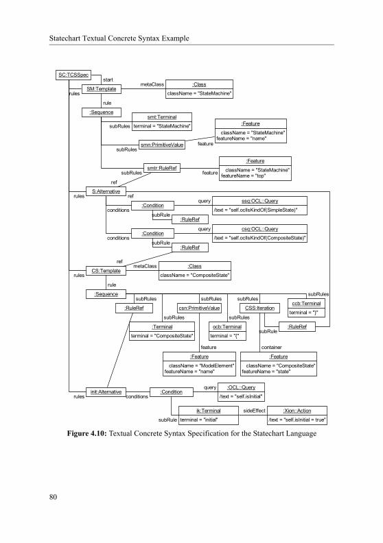
Integrating Distribution Concern in an UML Model
A.2 Integrating Distribution Concern in an UML Model
With the rapid growth of the Internet and the associated web services revolution, distributed systems become more and more pervasive setting up new standards for modern industries. Current enterprise applications consist of heterogeneous components written in different programming languages and distributed in heterogeneous environments that comprise dif-ferent hardware platforms, operating systems, data bases, and network protocols. The only way of masking these differences within an enterprise, or between enterprises, is by relying on middleware infrastructures, which can integrate diverse software components and allow them to interoperate effectively.
This section shows how an improvement step may be accomplished in an LDE devel-opment process as depicted by figure A.2 when the modeling language of the more concrete layer is an extension of the more abstract layer. In a first step, we will consider the abstract system to be the description in pure UML class diagrams of the business model. The goal of the step is to integrate the distribution concern using a UML profile. The outcome of that first step will become the abstract system of a second refinement step that will be in charge of adapting the distributed system to the CORBA [ABB+04] middleware platform, using a second profile. To use an MDA terminology, we break here the strict separation between platform-independent models (PIM) and platform-specific models (PSM) by attributing dif-ferent PIM or PSM roles to an abstraction layer. One may find a similar architecture in [ADvSP04]. As discussed in section A.2.3.1, the second profile inherits the first one using an higher-order hierarchy mechanism [Ern03]. If we believe that it is good LDE design when working with UML (or any profile-enabled language that is used in the two layers of a refinement step), this is not at all a mandatory requirement for applying LDE. Nor it is mandatory to use languages like UML or profile mechanism to practice good LDE.
This example is part of the enterprise fondue method [SS03, Sil06] and is further described in [SFS04a], though an overview is given in section A.2.2, especially regarding the distribution concern.
SystemSystemDistributed Model for CORBA (UML+Profile2)
Code
System
System
Code Generation
Code
System
System
Code Generation
Code
Business Model (UML)
Distributed Model (UML+Profile1)
Code Generation
Figure A.2: Refinement Steps to Integrate a Distribution Concern with UML
134

Applying and Customizing LDE
A.2.1 From Object-Oriented Designs to Distributed Systems
From a rather pragmatic point of view, we argue in this section that UML diagrams lack precision when it comes to providing specific distribution information that is typically required for generating distribution code out of UML models. We also provide a simple example for business model expressed in UML.
Let’s consider the object-oriented design of a simple Bank system, like the one illus-trated in figure A.3. We consider the example to be enough self-explaining for not entering into more details. It is important to mention nevertheless that not all designs follow the design by contract principles [JM97, BJPW99]. Typically, the interfaces in figure A.3 do not exist and clients act directly on the Bank, or on the Account, respectively. In that case, an intermediate “extract interface refactoring” [FBBO99, MB05] step is required in order to refactor the design and enforce good design principles.
Once we have a “good” design, based on interfaces, we would like to automate the distribution of such object-oriented designs on different middleware infrastructures, and we would like to achieve this as transparently as possible for the developer.
One key aspect of distributed systems is their location transparency. Typically, reg-istries are used to store the location of distributed objects. Clients find and use services (i.e., the interfaces of distributed objects that were already bound into registries) and do not care where they are located. Flexibility is very much increased, since distributed objects can be moved around and run on different machines, without any impact on the client side. It is only the information published in registries, and the registries themselves, that clients and distributed objects must agree upon.
* 1bank
accounts
Client
Bank
+createAccount(name : String, bal : Double) : AccountI+getAccount(name : String) : AccountI+transfer(ac1 : String, ac2 : String, amount : Double)#getAccountList() : Account [*]
«Interface»AccountI
+getBalance() : Double+withdaw(amount : Double)+deposit(amount : Double)
Account
-name : String-balance : Double
+getBalance() : Double+withdaw(amount : Double)+deposit(amount : Double)-setBalance(amount : Double)
«Interface»Bank
+createAccount(name : String, bal : Double) : AccountI+getAccount(name : String) : AccountI+transfer(ac1 : String, ac2 : String, amount : Double)
Figure A.3: The Bank Example
135

Enterprise Fondue and the Distribution Concern
Besides binding distributed objects into registries, there is also the problem of distrib-uted interfaces. If we have a closer look at the Bank::createAccount(...) or Bank::getAccount(...) methods, we notice they both return AccountI interfaces back to the client. If we consider, for example, the CORBA technology for implementing the distributed system, code generators must generate a CORBA IDL for the AccountIinterface as well, otherwise the AccountI interface cannot be passed around in a CORBA distributed setting. As a consequence, this interface must have been previously marked as distributed inside the design model, so that code generators know to treat it properly.
As a conclusion, in order to be able to generate distribution code for a specific mid-dleware infrastructure, design models must be refined and enhanced with distribution related information. But the question is how to model such distribution-related information in UML? How to specify that an interface should be distributed? How to specify that an object instance of class Bank should be the entry point of the distributed system? How to differentiate that object instance from other objects in the model in order to be able to bind it into a naming registry? How to infer that, because the BankI interface should be distrib-uted, the AccountI interface should be distributed as well?
Of course, we are aware that component-oriented models address some of these issues up to a certain level through component and deployment diagrams. However, from the implementation point of view, when it comes to generating distribution code, we still have to rely on object-oriented programming constructs and specific middleware support. There-fore, the work presented in this paper focuses only on the distribution of object-oriented designs, presenting new UML modeling elements for addressing distribution, and stressing the amount of distribution code that can be automatically generated from the enhanced object-oriented models. Moreover, we believe that it is a very good preliminary step before analyzing the actual support for generating a similar amount of distribution code out of component-oriented designs based on information that can be retrieved or inferred from component and deployment diagrams.
A.2.2 Enterprise Fondue and the Distribution Concern
The Enterprise Fondue software development method brings together four important para-digms in software engineering, namely Component-Based Software Engineering (CBSE), Separation of Concerns (SoC), Model Driven Architecture (MDA), and Aspect-Oriented Programming (AOP), and shows how they can complement each other at different stages in the development life-cycle of enterprise, middleware-mediated applications. The method identifies five layers corresponding to different levels of abstraction, each layer addressing specific concerns that pertain to enterprise applications in general. Model transformations are used to refine design models inside the same layer, or between different layers, along specific concern-dimensions.
136

Applying and Customizing LDE
For consistency reasons, we tend to use the terms middleware-specific concern-dimensions in relation with the refining activity (“refining along a dimension”), and middle-ware-specific concerns in all other contexts. Nevertheless, both terminologies refer to the same concepts, i.e., distribution, concurrency, transactions, security, and so on.
Figure A.4 presents how the refinement process in Enterprise Fondue evolves from one abstraction level to the next one by incremental refinements along different concern-dimensions. We use a mixed notation for representing the process flow, on one hand, and for representing UML 2.0 dependencies or relationships between modules, on the other hand.
The first refinement step is performed by the MTL1 transformation. In the Enterprise Fondue terminology, we say that MTL1 refines along a middleware-specific concern-dimen-sion (Cx) according to an associated UML profile for that concern. This transformation is performed inside the Concern-Driven Object-Oriented Models Layer (L2) as defined in Enterprise Fondue. MTL1 will refine here along the distribution concern-dimension. How-ever, several MTL1s can be applied at this layer, addressing different middleware-specific concerns.
The second refinement step is performed by the MTL2 transformation, that is, in the Enterprise Fondue terminology, along the technology-dimension (Ty). Actually, in the Enterprise Fondue, MTL2 is a sequence of model transformations (not necessarily two), but for sake of clarity, we will avoid that aspect. Globally, the transformation correspond to refinement along middleware-specific concern-dimensions according to UML profiles for those concerns on the specific technology (Cx on Ty). All these transformations are per-formed inside the Technology-Dependent Layer (L1) as defined in Enterprise Fondue. For example, by refining along the CORBA technology-dimension, we will first apply the UML profile addressing the distribution concern on the CORBA technology (the CORBADistri-butionRealizationProfile, as it will be introduced in section A.2.3.3).
Finally, the code generation step is handled by the Parallax [SS05, Sil06] tool config-ured to handle the concern with the technology. Parallax also covers both the Platform-Dependent (Pz) and Language-Dependent (Lw) layers of Enterprise Fondue (L0).
A.2.3 UML Profiles to Address the Distribution Concern
The hierarchy of UML profiles presented in this section addresses the distribution concern in an MDA-oriented fashion at three different levels of abstraction: at a platform-indepen-dent level, at an abstract realization level, and at a concrete realization level for the CORBA technology (see figure A.5). We rely on specialization relationships between dis-tribution profiles: each specialization introduces new modeling elements or simply refines the already existing ones.
137

UML Profiles to Address the Distribution Concern
A.2.3.1 UML Distribution Profile
The purpose of distribution is to logically, or even physically separate communicating ele-ments, typically a “core” system from its users. In UML, what these elements know about each other is described in terms of interfaces. UML interfaces are defined as sets of coher-
Figure A.4: Refinement Process in Enterprise Fondue
Plug-in forCx, Ty, Pz, Lw
UML Design Model
UML Metamodel
UML Profilefor
Concern Cx
UML Modelwith elements for
Cx
UML Profilefor
Cx on Ty
UML Modelwith elements for
Cx on Ty
MTL1
MTL2
Parallax
«conformsTo»
«apply»
configuration
configuration
Codefor Platform Pzin Language Lw
XML-Config-File
«uses»
in
in
out
in
out
«apply»
in
in
out out
Refinement alongtechnology-dimension
Refinement alongplatform-dimension &language-dimension
L0
L1
L2
Refinement alongmiddleware-specificconcern-dimension
Cx - a middleware-specific concern, e.g., distributionTy - a middleware technology, e.g., CORBAPz - a middleware platform, e.g., OpenORBLw - a programming language, e.g., JavaMTL - MTL Model Transformation
«merge»
138

Applying and Customizing LDE
«metaclass»InstanceSpecification
1..*
distributed 0..*
servants
«stereotype»Distributed
«stereotype»Servant
«stereotype»NamingRegistry «stereotype»
NameExposition
«stereotype»CORBANamingService
host : Stringport : String
«stereotype»CORBANameExposition
{inv: self.exposed.oclAsType(CORBANameExposition)->forAll(exp1, exp2 : CORBANameExposition | exp1 = exp2 or exp1.exposedNames->intersection(exp2.exposedNames)->isEmpty())}
«profile»DistributionProfile
«metaclass»Interface
{inv: self.classifier->forAll(c | c.conformsTo(self.distributed))}
«stereotype»InterfaceExposition«stereotype»
ServiceRegistry
publisher
exposed
«metaclass»Comment
«stereotype»Publisher
«stereotype»Exposition
*1
*
{inv: self.annotatedElement ->includesAll(Set{ self.servant, self.publisher})}
1..*
{inv: self.annotatedElement->includesAll(self.exposedInterfaces) inv:self.publisher.oclIsKindOf(InterfaceExposition) inv:self.exposedInterfaces->forAll(i | self.servant.distributed.compliesTo(i))}
«stereotype»NameExposition
exposedNames : String [1..*]
«metaclass»Interface
«stereotype»NamingRegistry
«stereotype»Servant
«stereotype»PublishedServant expositions
«profile»CORBADistributionRealizationProfile
«merge»
«profile»AbstractDistributionRealizationProfile
«merge»
exposedInterfaces
servant
1
{inv:self.publisher.oclIsKindOf(NamingRegistry)}
Figure A.5: MDA-Oriented Hierarchy of UML-D Profiles
139

UML Profiles to Address the Distribution Concern
ent publicly available features and obligations, fulfilled at runtime by instances of classes realizing them. The distribution process should end-up in subsystems communicating through known interfaces. We qualify these interfaces as distributed. This additional infor-mation can be added to the model of the system by applying the DistributionProfilepresented in figure A.5 .
To make a difference between what interfaces are used for communication within a system and between systems, the profile defines the «Distributed» stereotype as an extension of the Interface metaclass as shown in figure A.5 . All features defined within a «Distributed» interface are remotely available. In the case a «Distributed»interface extends other interfaces, available remote features are only those defined within a «Distributed» interface, allowing in this way to separate between distributed and not distributed interfaces even within the same hierarchy of interfaces. For instance, the follow-ing OCL query may be defined within the scope of the «Distributed» stereotype to find all its remotely available operations:context Distributed def: allRemoteOperations : Set(Operation) = self.ownedOperation->union( self.allParents() ->select(oclIsKindOf(Distributed)) .ownedOperation )
We have assumed here that the predefined OCL oclIsKindOf operation holds true if a model element has the stereotype passed as parameter. A similar query may also be defined to know about all remotely available attributes.
Nevertheless, it is also necessary to indicate key instances that the environment needs to know in order to start-up an interaction with the system as an entity. They are identified by applying the «Servant» stereotype. As these instances receive invocations from the environment, their class must realize a “well-known” «Distributed» interface, that is why «Servant» and «Distributed» stereotypes are associated as shown in figure A.5 . This allows one, once these stereotypes are applied on corresponding instances and interfaces, to indicate at the model level what are the «Servant» instances of a «Distributed» interface, and what are the «Distributed» interfaces of a «Ser-vant» instance. As indicated by multiplicities of the association , a «Servant» instance must realize at least one «Distributed» interface, otherwise a client application does not know how to communicate with it. On the other side, a «Distributed» interface may be connected to any number of «Servant» objects. If none, it means the given interface does not participate in any interaction set-up. If a «Distributed» interface defines many «Servant» objects, this means the system has many entry points with this interface.
For the profiled model to be consistent, it is important to add a constraint stating that one of the classes of each «Servant» object must realize the «Distributed» interface it
140

Applying and Customizing LDE
is related to through the distributed association end . This constraint is given in figure A.5 .
Thought very comprehensive and understandable, one may remark that associations between stereotypes are not allowed in UML. Nevertheless, a stereotype may declare a tag definition whose type is a metaclass. We define thus the association from stereotype S1, which extends metaclass C1, to stereotype S2, which extends metaclass C2, by a tag defini-tion in S1 whose type is C2 with the additional constraint that the corresponding tagged val-ues are stereotyped with S2. Tag definition are crossed in case of bidirectional association.
A.2.3.2 UML Abstract Distribution Realization Profile
The purpose of the AbstractDistributionRealizationProfile is to provide a framework to describe which «Servant» instances are made available to the outside world, how, and where. We enter here the technology-dependent layer (L1) described in figure A.4. As this profile specializes entities described in the DistributionProfile, it merges this latter profile and as a consequence integrates into it all its stereotypes and tag definitions.
The «PublishedServant» stereotype is a specialization of «Servant», in order to show that «Servant» instances may be exposed to the outside world. Such «Servant»instances will be further referred as «PublishedServant» instances (PSI). Due to the specialization, the «PublishedServant» stereotype inherits the InstanceSpecifi-cation base class, the distributed tag definition, and the constraint , which must now hold for all elements conforming to this stereotype as well.
A «Publisher» is a «PublishedServant» instance specialized in making avail-able a given «PublishedServant» to the outside world. This means that in order to interact with a PSI, an actor from the environment should first locate it by sending a request to a «Publisher» instance. How an external actor localizes a «Publisher» is voluntar-ily left unresolved and should be defined by specializing the «Publisher» stereotype according to the concrete technology to be used. This is the reason why the «Publisher»stereotype is abstract. For instance, if the Bank example of figure A.3 is made distributed, a Client should first retrieve the right «Servant» Bank instance by sending a request to a «Publisher» instance. Because the «Publisher» stereotype inherits the «Pub-lishedServant» stereotype, an instance stereotyped «Publisher» is also a PSI, and may be published by another «Publisher» instance.
The relationship between a «PublishedServant» and a «Publisher» is expressed by the «Exposition» stereotype. Unfortunately, there is not really an ideal relationship between instances in the UML metamodel that this stereotype could extend. Therefore, we decided to make the Comment metaclass the base class of this stereotype. Information of what is published and who is the publisher is gathered through the associations and respectively. The constraint requires all the «Exposition» com-
141

UML Profiles to Address the Distribution Concern
ments to be attached to both the «Servant» and the «Publisher» instances. A given PSI may be published several times within several «Publisher» instances, and con-versely, a «Publisher» may expose several PSIs, all these relationships being modeled through «Exposition» comments.
«Publisher» and «Exposition» are abstract stereotypes. Therefore, they cannot be applied to a model element as such, because some registration information needs to be provided. We include therefore in the profile a kind of “reference implementation”, although it would be possible to define an additional independent profile that extends the AbstractDistributionRealizationProfile and describes additional information required by another implementation mechanism.
As a first reference implementation mechanism, we propose to register a PSI by names, which are character strings, within a «Publisher» instance. We therefore define «NamingRegistry» as an extension of the «Publisher» stereotype, together with the «NameExposition» as an extension of the «Exposition» stereotype. The registration names are stored in the exposedNames tag definition, that is defined in the «NameExpo-sition» stereotype. This tag definition has a 1..* multiplicity meaning that the PSI can be exposed by at least one name. A «NamingRegistry» may only publish PSIs through a «NameExposition», and a «NameExposition» may only refer to a «NamingRegis-try». This is enforced by the constraint . This kind of exposition mechanism looks like the one of the phone directory of residents (“white pages”).
As a second mechanism, we propose to register a PSI with the services it can offer. For instance, one can ask the environment for a printer, provided that there is a printer that knows about how to print PostScript documents. This mechanism is described by the couple of stereotypes «ServiceRegistry» for the publishing part and «InterfaceExposi-tion» for the exposition part. This time the registration is performed by means of inter-faces, referenced by the tag definition exposedInterfaces within the «InterfaceExposition» stereotype. Again, a constraint ( ) states that they should be used together and only together. This kind of exposition mechanism looks like the one of the business phone directory (“yellow pages”).
A.2.3.3 UML CORBA Distribution Realization Profile
The CORBADistributionRealizationProfile addresses the realization of the distri-bution concern when the implementation is supposed to use the CORBA technology. It takes advantage of the AbstractDistributionRealizationProfile by adapting its abstract concepts to the CORBA technology, so that a code generator has enough informa-tion to generate the necessary distribution code.
The «CORBANameExposition» stereotype represents a «NameExposition»using the CORBA technology. It extends the «NameExposition» but does not add partic-ular information to it. The idea here is to state clearly that a PSI is registered by name using
142

Applying and Customizing LDE
the CORBA technology. The same holds for the «CORBANamingService» stereotype that extends the «NamingRegistry». In order for an actor of the environment to find the «CORBANamingService», we add the host and port tag definitions. As previously, an OCL constraint ( ) enforces that these two stereotypes work together and only together. This constraint also enforces that exposition names are all different within the context of a «Publisher».
We chose to describe here only the CORBA technology, but the same principle may be applied to any kind of middleware technology, possibly with additional intermediate pro-file specialization steps.
A.2.4 MTL Model Transformations for Applying the UML-D Profiles
We present in this section the model transformations that incrementally refine existing design models according to the UML-D Profiles introduced in the previous section using the MTL language (see section 2.1.3.2). The Bank example (figure A.3) is used for illustrating the refinement process.
A.2.4.1 Refining Along the Distribution Concern-Dimension
The distribution transformation (MTL1-D) is refining centralized design models along the distribution concern-dimension according to the DistributionProfile presented in section A.2.3.1. Its name indicates, on one hand, that it belongs to the MTL1 family of trans-formations (as shown in figure A.4), and on the other hand, that it is related to the distribu-tion concern.
In order to achieve the distribution, the transformation requires the developer to pro-vide information about the interfaces that the «Servant» object should realize. These spe-cial interfaces will be further referred as «Servant» interfaces (SIs). If several «Servant» objects are needed, then the transformation may be called several times. As already mentioned in section A.2.1, we rely on the premise that all interactions with the environment occur through well-defined interfaces.
In the first step, the MTL1-D transformation “imports” the DistributionProfileinto the model, making available the UML extensions it defines. The second step is to find the right classifier for the «Servant» object. Note that if more than one classifier realizes all the interfaces the developer has specified, then the MTL1-D transformation may choose an arbitrary one, or ask the developer to choose among the possible realizations; if no class is found, then the transformation ends in error, without modifying the model. Once the right classifier is found, the corresponding SIs are marked with the «Distributed» stereotype and an object instance of the found classifier is created and marked with the «Servant»stereotype. As these stereotypes are associated, it is still necessary to provide crossed tagged values as specified in section A.2.3.1. This means that the «Servant» object refer-ences its SIs by means of the distributed tagged value, and each SI references its
143

MTL Model Transformations for Applying the UML-D Profiles
«Servant» objects by means of the servants tagged value, according to the Distri-butionProfile.
The last step of the MTL1-D transformation is to infer all interfaces that participate in interactions with the environment and to stereotype them «Distributed» as well. To this end, the transformation explores, starting from the provided SIs, the types of parameters of all operations, and the types of all attributes of each interface. While exploring, all encoun-tered interface types are stereotyped «Distributed» (if not yet the case), and recursive explorations are started for each such interface. The MTL code for this exploration is shown in figure A.6.
As an example, we show in figure A.7 the outcome of the MTL1-D transformation on the Bank example when BankI is the only SI requested by the developer. As you can see, BankI gets stereotyped as «Distributed» ( ). An object of class Bank, the only clas-sifier realizing the BankI interface, is created and stereotyped «Servant» ( ). The tagged values are shown in grey colored notes. Due to the association between «Distrib-uted» and «Servant» stereotypes (as defined in the profile), the «Distributed»BankI interface references its SIs by means of the servants tagged value ( ), and the «Servant» b references the «Distributed» BankI interface by means of the dis-
//Within the MTL class Distributor treatOperationDependencies() { i1 : Standard::Iterator; i2 : Standard::Iterator; pa : m::Core::Parameter; i1 := toDistribute.feature.getNewIterator(); while i1.isOn() { if i1.item().oclIsKindOf(!m::Core::Operation!) { i2 := i1.item() .oclAsType(!m::Core::Operation!) .parameter.getNewIterator(); while i2.isOn() { pa := i2.item(); new Distributor() .init(self,pa.type).run(); i2.next(); } } i1.next(); }}
Figure A.6: The MTL1-D Transformation: Exploring Operations Part
144

Applying and Customizing LDE
tributed tagged value ( ). As the «Distributed» BankI interface contains opera-tions, such as createAccount and getAccount, involving the AccountI interface, this last interface is stereotyped «Distributed» as well, but with an empty servantstagged value ( ).
A.2.4.2 Refining Distribution Along the CORBA Technology-Dimension
The CORBA distribution realization transformation (MTL2-D) is refining distributed mod-els along the CORBA technology-dimension. More precisely, it refines models, to which the DistributionProfile was already applied, to ones that are more specific about how the distribution concern is actually implemented on the CORBA technology. As previ-ously, the name indicates that it belongs to the MTL2 family of transformations (as shown in figure A.4), on one hand, and that it is related to the distribution concern, on the other hand.
In order to be able to apply the CORBADistributionRealizationProfile, the MTL2-D transformation requires the developer to provide all the new information that this profile adds with respect to the DistributionProfile. Indeed, MTL2-D needs to be able to provide each CORBA publisher (i.e., CORBA Naming Service [BDII02], «CORBA-NamingService») with its name, host and port, and each PSI with its expositions («CORBANameExposition») containing the names to be exposed (exposedNames) and the publisher to be used (publisher). The transformation does not integrate any «InterfaceExposition», which is more related to the Trading Service [ABH+00] of CORBA that is not discussed in this paper.
Like for MTL1-D, the first step of the MTL2-D transformation is to “import” the CORBADistributionRealizationProfile into the model. The MTL2-D also “imports” standard CORBA libraries, like the interface of the CORBA publisher, which is
«Interface»«Distributed»
BankI
«Interface»«Distributed»
AccountI
Bank Account
«Distributed» servants = Set{b}
«Servant»b:Bank
«Servant» distributed= Set{BankI}
Class DiagramObject Diagram
«Distributed» servants = Set{}
Figure A.7: The MTL1-D Outcome for the Bank Example
145

MTL Model Transformations for Applying the UML-D Profiles
org::omg::CosNaming::NamingServiceExt. Then, the transformation creates «CORBANamingService» publisher objects and sets their host and port tagged values according to the provided parameters. Since «CORBANamingService» inherits from the «Servant» stereotype the distributed tag definition, and because of its multiplicity 1..*, it is necessary to provide it with a value. Other inherited tagged values are not man-datory as their lower bound multiplicity is zero and because they would have no meaning for the «CORBANamingService» publisher. Moreover, as the «CORBANamingSer-vice» publisher instance provides behaviors described in the NamingServiceExt inter-face, this interface must be stereotyped as «Distributed». The distributed and servants tagged values are used to relate the instance and the interface together.
At the end, the MTL2-D transformation creates the expositions as specified by the developer. As defined in the profile, each «CORBANameExposition» is a Comment on the PSI and the «Publisher» instance, which are referenced through the servant and publisher tagged values respectively. Both the PSI and the «Publisher» («CORBAN-amingService» in our case) know about the «Exposition» comment by means of the expositions and exposed tagged values respectively. The exposed names of a «COR-BANameExposition» are stored in the exposedNames tagged value. figure A.8 shows the MTL code for this last step.
The outcome of the MTL2-D transformation for the Bank example is shown in figure A.9. The source model for the transformation is the one shown in figure A.7. The MTL2-D provides one «CORBANamingService» publisher object cns ( ) and sets its distributed tagged value to reference the NamingServiceExt interface. The «Dis-tributed» stereotype was applied to this last interface and its servants tagged value was set to reference the cns, but this is not depicted here. The diagram also shows the bobject, which was applied the «PublishedServant» stereotype ( ). A new comment, named BankExposition, with stereotype «CORBANameExposition», represents the expositions ( ), and it is referenced by the expositions and exposed tagged values in the b and cns instances respectively. This comment annotates these instances and refer-ences them with the servant and publisher tagged values respectively. For the sake of
146

Applying and Customizing LDE
//The exposition //- publisher is the publisher object //- servant is the published servant object //- profile is an MTL proxy for the // CORBADistributionRealizationProfile //- expositionName is the provided name // of the exposition //- publishedNames are the names the servant // is registered with ex := new m::Core::Comment(); ex.name := expositionName; associate ( comment := ex : m::Core::Comment, annotatedElement := servant
: m::Core::ModelElement); associate ( comment := ex : m::Core::Comment, annotatedElement := publisher
: m::Core::ModelElement); profile.applyStereotype(ex, profile.cORBANameExposition);
profile.setTaggedValueData(servant, profile.publishedServantExpositionsTag,ex);
profile.setTaggedValueData(publisher, profile.publisherExposedTag, ex);
profile.setTaggedValueData(ex, profile.expositionServantTag, servant);
profile.setTaggedValueData(ex, profile.expositionPublisherTag, publisher);
profile.setTaggedValueData(ex, profile.nameExpositionExposedNamesTag, publishedNames);
Figure A.8: The MTL2-D Transformation: Creating Exposition Part
147

Conclusions
clarity, all tagged values have been provided, even if empty, and classified according to the stereotype in which they where declared.
A.2.5 Conclusions
The Enterprise Fondue method proposes a systematic approach for addressing pervasive services in an MDA-compliant manner, at different levels of abstraction, through incremen-tal refinement steps along middleware-specific concern-dimensions. In this section, we introduced the key elements that support the Enterprise Fondue method when refining along the distribution concern-dimension, namely: (1) the UML Profiles for Distribution (UML-D Profiles) that address the distribution concern in an MDA-oriented fashion at three different levels of abstraction (platform-independent level, abstract realization level, and concrete realization level), (2) the model transformations that incrementally refine existing design models (within the same or between different MDA-levels) along distribution-related con-cern-dimensions and in conformance to the proposed UML profiles, and (3) the Parallax support for generating code towards specific middleware infrastructures. The CORBA tech-nology was used to illustrate how the refinement process evolves on a concrete example.
This example follows the prescriptions of LDE. It applies a stepwise refinement pro-cess taking advantage of model transformation. This section actually introduced Enterprise Fondue as an LDE methodology by stating, as prescribed in section 2.1.1 on page 11, (1) what are the levels of abstraction and their platforms (Business Model, Distributed Model, Distributed Model for CORBA), (2) what are the languages to use (UML, UML + Distri-buitonProfile, UML + CORBADistributionRealizationProfile), (3) the refinement process
«PublishedServant»b:Bank
«CORBANamingService»cns:NamingServiceExt
«CORBANameExposition»BankExposition
«Exposition» servant= b publisher= cns «NameExposition» exposedNames= Set{'BCV'} «CORBANameExposition»
«Servant» distributed= Set{Bank} «PublishedServant» expositions= Set{BankExposition}
«Servant» distributed= Set{NamingServiceExt} «PublishedServant» expositions= Set{} «Publisher» exposed= Set{BankExposition} «NamingRegistry» «CORBANamingService» host= '127.0.0.1' port= '3028'
Figure A.9: The MTL2-D Outcome for the Bank Example
148

Applying and Customizing LDE
(MTL1 and MTL2 transformations), (4) the code generation process (Parallax), even though (5) verification and testing were left aside.
The example presented in this section also shows how an LDE methodology can be tailored to support new concepts introduced in intermediate steps. Indeed, the genuine LDEmethodology states that one should develop the system under study using the UML lan-guage. Then, code is generated out of the UML model. We introduced here new concepts relative to distribution in a first step, and distribution using the CORBA platform in a sec-ond step. For the LDE methodology to be properly tailored, we enhanced the modeling lan-guage (i.e. UML) using a tag mechanism, and we introduced semi-automatic improvements. A problem is that code generation needed to be tailored as well. In our example, we used the aspect-oriented customization mechanism offered by the Parallax code generator [SS05].
Figure A.10 shows a generalization of LDE methodology customization. At the left, the genuine LDE process states that the system under study must be modeled first using the L1 language. The model is then improved by I1, I2 and I3, producing specifications using the L2, L3, and L4 languages, respectively. A final code generation step is performed to obtained the final implementation. The right part of the figure shows the same LDE process, slightly enhanced, to integrate a new concern, following the example of the distribution concern that introduces new concepts to the UML language, as presented in this section. The new concern is introduced by an II improvement (following the example of the MTL1-D and MTL2-D transformations), that integrates the concern using an enhanced version of the L2 language (L2++). For those enhancements to be lost neither by further improvements (I2, I3, and code generation), nor by languages of the next steps (L3, L4, and target code), improvements and languages needs to be customized either (I2++, L3++, etc.), unless the new concern is handled by a library (see section 1.1 on page 1). If languages can be custom-
L1L2L3
Code
I2
L4
Code Generation
L1L2
L2 ++
Code ++
L3 ++L4 ++
Code Generation ++
Enhancements
I3
I1
III2++
I1
I3++
Figure A.10: Customizing an LDE Process
149

AspectMTL: Customizing Improvements
ized using higher-order hierarchies or tag mechanisms (as shown in this section), and code generation can be customized using the approach proposed by Parallax [Sil06], one needs means to customize improvements. We propose in the next section a mean to customize improvements, when they are defined as MTL model transformation.
A.3 AspectMTL: Customizing Improvements
Model transformations are undoubtedly one of the key technology in the realization of the LDE vision, and thus one need transformation languages to apply an LDE process [SK03]. Among other usages, model transformations are the ones responsible for refining models for example to map them to concrete middleware-based implementations, providing thus an elegant approach to adapt system specifications to the peculiarities of the new middleware infrastructures that do not cease to appear as an example in previous section.
LDE also promotes reuse and adaptation of existing languages to particular needs. Model transformation languages thus may be adapted to the needs of a particular LDEmethodology (i.e. an LDE instance). We propose in this part to improve reusability of the transformations in use in the LDE process presented in previous section, thus reusability of the complete methodology. This will require to change the Model Transformation Language (MTL - see section A.1.2) that is employed to implement the transformations.
Model transformations should be able to act on any kind of model of any kind of meta-model. Since model transformations are at the same time models compliant with the meta-model of the transformation language, model transformations should be able to transformother model transformations independently of their metamodels. As a consequence, all existing model transformation languages (to our knowledge) implement such a “reflective”behavior. However, the "reflective" use of model transformations is not trivial.
Typically, writing model transformations for driving the development process of domain-specific applications requires the transformation developer to be familiar with the metamodel of that specific domain and with the syntax of the model transformation lan-guage used – and no more than that. As a consequence, many transformation developers are not at all familiar with the metamodel of the transformation language itself, and thus they are not capable of writing "reflective" model transformations, i.e., model transformations that transform already existing model transformations.
We present here a solution inspired by Aspect-Oriented Programming (AOP) [KLM+97] approaches. We have designed and implemented an MTL weaver that modifies MTL transformations according to some weaving behavior that is specified as a special kind of MTL transformations, called MTL-aspects. The MTL transformation produced by the MTL weaver can be immediately used for refining application models.
As in the case of AspectJ [KHH+01], which is an aspect-oriented extension to Java, the syntax defining the weaving behavior in MTL-aspects is a small AOP-like extension to
150

Applying and Customizing LDE
the MTL language itself. In this way, relying on a few high-level AOP-like but MTL-based constructs for defining the weaving behavior, average MTL transformation developers should not have any problems using this MTL extension straightforwardly for defining their "reflective" model transformations.
The entire compilation process of the MTL language as presented in figure A.1 of section A.1.2 relies on the model of the MTL transformation T itself, which complies with the well-defined MTL metamodel. Therefore, steps , , and of figure A.1 can be viewed as special transformations acting on the MTL model of the transformation T itself. Besides these three steps, it is at this MTL model level of the MTL transformations that new special transformations may be defined in order to change the very behavior of those MTL transformations. Following this idea, our MTL weaver is indeed implemented as such a spe-cial transformation, acting on the MTL models of the MTL transformations and transform-ing them according to the weaving behavior defined in MTL-aspects, as we will see in section A.3.2.
A.3.1 Motivations
We present in this section how currently applied MTL transformations benefit from the weaving support provided by the MTL weaver, promoting the separation of concerns para-digm even at level of model transformations.
Separation of concerns [Par72] and modularity are fundamental techniques of soft-ware engineering. Decomposing software into smaller, more manageable and comprehensi-ble parts, each of which encapsulating and addressing a particular area of interest, called a concern, is a well-proven method towards developing applications that are easy to config-ure, adapt, or extend according to changes in the requirements specification.
Middleware is an essential element in large distributed systems such as those that sup-port enterprise applications, requiring multiple heterogeneous components to interoperate. Previous section has shown that middleware, like software in general, is subject to con-cerns. Several concern-dimensions about middleware can be grouped into a category called Middleware Services, as the middleware addresses specific concerns of a system, such as distribution, concurrency, security, or transactions. An extended list of categories that group several middleware-specific concern-dimensions can be found in [Sil06]. In the context of Enterprise Fondue we defined several MDA-oriented UML profiles that address middle-ware-specific concerns at different levels of abstraction. MTL transformations were used to incrementally refine existing design models (within the same or between different MDA-levels) along middleware-specific concern-dimensions and according to the UML profiles defined. A complete example of applying the Enterprise Fondue method for addressing the distribution concern in the concrete case of the CORBA technology was also presented. The proposed UML-D Profiles address the distribution concern at three different MDA-levels of abstraction: platform-independent level (the DistributionProfile), abstract realiza-
151

Motivations
tion level (the AbstractDistributionRealizationProfile), and concrete realiza-tion level (the CORBADistributionRealizationProfile).
Based on the support provided by the MTL weaver, we refactored the MTL transfor-mation that refined application designs in the context of the Enterprise Fondue method along the distribution concern-dimension and according to the DistributionProfile. Out of one big model transformation that performed the entire refinement, we have now one standard MTL transformation that performs the copy of an input model to an output model, both models being compliant with the same UML metamodel, and a very small MTL-aspect that defines the weaving behavior according to the DistributionProfile that has to be applied. Both the MTL-Copy transformation and the MTL1-D-Aspect are now fully sepa-rated as they should be, since they address totally different concerns. Figure A.11 a sketches the refinement process in the presence of the MTL1-D-Aspect, or more general in the presence of MTL-aspects. Its name, MTL1-D-Aspect, was chosen in accordance with the MTL1-D transformation. The MTL-Distribution-Copy transformation is the result pro-duced by the weaver when modifying the MTL-Copy transformation according to the weav-ing directives defined in the MTL1-D-Aspect.
A more complex example is shown in figure A.11 b, where the metamodel of the input and output models changes. In this example we move from a UML model to a Java model ready to be mapped to concrete Java implementation. Considering as input the output model of the previous refinement process, we refine this time along the RMI-technology and Java-language concern-dimensions as defined in the context of the Enterprise Fondue method. While the MTL-UML2Java deals with transforming any UML model to its corre-spondent Java model (relying on their respective metamodels), the MTL2-D-Aspectaddresses how distribution specific elements in the UML model are transformed into their Java model counterparts when employing RMI as their implementation technology. For instance, interfaces marked as «Distributed» in the UML model will extend java.rmi.Remote in the Java model; similarly, the class of the object marked as «Ser-vant» will extend java.rmi.UnicastRemoteObject in the Java model, and so on. Once again, the name, MTL2-D-Aspect, was chosen in accordance with the MTL2-Dtransformation even though we considered this time another technology, i.e., we have cho-sen RMI instead of CORBA. The MTL-RMI-UML2Java transformation is the result pro-duced by the weaver when modifying the MTL-UML2Java transformation according to the weaving directives defined in the MTL2-D-Aspect.
As can be seen in figure A.11, the support provided by the MTL weaver has enabled us to make modular the different concerns in stand-alone units of encapsulation represented by MTL-aspects. In this way, we give transformation developers not only the possibility, but also the means to rely on the well-proven power of separation of concerns even at model transformation level. Moreover, the size of such MTL-aspects is very much reduced, com-pared to their corresponding implementation in the initial MTL transformations, since they rely on the MTL weaver which is now the one carrying all the burden of the weaving. The
152

Applying and Customizing LDE
example presented in figure A.11 a is reconsidered further on in section A.3.2 where we discuss in more details its complete implementation.
Besides encapsulating middleware-specific concerns into MTL-aspects as presented in this section, the number of possible usages of such MTL-aspects is unlimited since the support provided by the MTL language enables us to implement almost anything in the MTL weaver, and thus, the expressiveness power that could be provided to transformation developers through the MTL extension syntax may be very broad, covering all possible and impossible needs that developers may think of.
A.3.2 The MTL Weaver
Reusability has always been an important concern in the software development industry due to its potential to reduce the cost of software development. During the last decade, different
ledomateMLMU ledomateMLMU ledomateMavaJ
avaJ2LMU-IMR-LTMypoC-noitubirtsiD-LTM
LTMnoitamrofsnarT
noitinifeD
LTMnoitamrofsnarT
noitacilppA
avaJ2LMU-LTMypoC-LTM
htiwledoMLMUnoitubirtsiD stnemelEledoMLMU
htiwledoMavaJnoitubirtsiD stnemelErof IMR
tcepsA-D-1LTM
eliforPLMUrof
noitubirtsiD
rofeliforPLMUIMR
noitazilaeRnoitubirtsiD
noitarugifnoc
noitarugifnoc
tcepsA-D-22LTM
»nievaew« »nievaew«
rofeliforPLMUtcartsbA
noitazilaeRnoitubirtsiD
1.Distribution 2.RMI and Java
Figure A.11: Refining along the Distribution, RMI-Technology,and Java-Language Concern-Dimensions
153

The MTL Weaver
levels of reuse have been proliferated, such as functions, procedures, classes, components, aspects, or even entire models. But how can we achieve the reuse of model transformations? How to adapt existing model transformations that already accomplish most of our needs?
The reuse of MTL transformations is currently promoted at the level of MTL librar-ies, which are some kind of light model transformation components. In this section, we present some implementation details and the provided facilities of an aspect-oriented sup-port that allows transformation developers to reuse existing MTL transformations and to easily adapt them in order to address new needs, or concerns, that the application under development has to incorporate. The main concepts of the MTL weaver are introduced along with the AOP-like extension to MTL for defining the weaving behavior in MTL-aspects. We also present an example showing both the input and the output of a con-crete weaving.
The standard MTL language already provides support for transformation developers to define MTL transformations that transform other MTL transformations. However, writ-ing such "reflective" MTL transformations still requires transformation developers to be familiar with the metamodel of the MTL language itself, a requirement that significantly reduces the number of such developers. In order to overcome this impediment for the MTL language, we propose a solution inspired by AOP approaches. We have designed and imple-mented an MTL weaver that modifies MTL transformations according to some weaving behavior that is specified in terms of weaving directives modularized in special stand-alone MTL transformation encapsulation units, called MTL-aspects. As in the case of AspectJ, which is an aspect-oriented extension to Java, the syntax defining the weaving behavior in MTL-aspects is a small AOP-like extension to the MTL language itself. In this way, relying on a few high-level AOP-like but MTL-based constructs for defining the weaving behavior, average MTL transformation developers should not have any problems using this MTL extension straightforwardly for defining their "reflective" model transformations.
The place of the MTL weaver in the MTL compilation process and the evolution of the MTL weaving process are presented in figure A.12, where the MTL transformation T is
MTLWeaver
Parser
Parser
T.mtllibrary
T.mtllibrary
A.mtllibrary
A.mtllibrary Type
Checker
CodeGenerator
T+A.tllPrecompiled
library
T+A.tllPrecompiled
library
T+A*.java Generated java transformation
T+A*.java Generated java transformation
MTLTransformation
T
MTL-AspectA
MTLTransformation
T+A
MTLWeaver
Parser
Parser
T.mtllibrary
T.mtllibrary
A.mtllibrary
A.mtllibrary Type
Checker
CodeGenerator
T+A.tllPrecompiled
library
T+A.tllPrecompiled
library
T+A*.java Generated java transformation
T+A*.java Generated java transformation
MTLTransformation
T
MTLTransformation
T
MTL-AspectA
MTL-AspectA
MTLTransformation
T+A
MTLTransformation
T+A
Figure A.12: The MTL Weaving Process
154

Applying and Customizing LDE
refined according to the weaving directives defined in the MTL-aspect A. The weaving pro-cess is very similar to the compilation process presented in figure A.1. First, both T and Aare parsed ( ) in order to transform the two text files into internal MTL models compliant with the MTL metamodel. The important change comes next, when the MTL Weaver ( ) reads the two internal models of T and A, and produces a new model instance (of the MTL metamodel) for the new MTL transformation T+A, which represents the result of modifying T according to the weaving directives defined in A. Even though it is not explicitly shown in figure A.12, the MTL weaver itself is implemented as an MTL transformation as well. Once this weaving step is finished, the normal compilation process can continue with the type checking step ( ), which produces a reusable precompiled MTL library, and the code gen-eration step ( ), which produces Java source files. Please notice that the weaving process results in a completely new MTL transformation, without making any changes to the origi-nal MTL transformation T. In this way, both transformations can independently be reused later on in order to transform application models. Moreover, the MTL-aspect A may be reused as well for refining other MTL transformations according to the same weaving direc-tives. Another remark is that we reused as is elements of the MTL "official" compiler of section A.1.2 so that only the MTL weaver had to be implemented.
A.3.3 MTL-Based Syntax for Describing the Weaving Behavior
There are two major requirements that an MTL-aspect must fulfill. First, it must clearly identify where the modifications have to be performed, and second, it must clearly define what are those modifications. In AOP terminology, a join point is a well-defined point in the execution of a program where additional functionality may be "injected". To identify such points in our weaving process, a pattern matching mechanism is used with respect to the names of the MTL libraries, MTL classes, MTL methods, etc. Both require-ments can be expressed using the MTL syntax as well, relying on small extensions that are detailed in this section.
One of the extension mechanisms proposed by the MTL language is the tagging facil-ity. Tags are key/value pairs associated either with an MTL library, an MTL class, or an MTL method. Since tags are part of the MTL metamodel, once they are analyzed by the MTL parser, they populate the internal MTL model representing the MTL transformation. This makes it possible for the MTL weaver presented in figure A.12 to access these tags and to use them for very different purposes. Since MTL-aspects only rely on the tag exten-sion mechanism to define additional weaving directives, it is possible to use the same parser for reading both MTL-aspects and MTL transformations, as shown in figure A.12 .
In order to give an example of an MTL-aspect that could play the role of A in figure A.12, we show in figure A.13 some snippets of the MTL1-D-Aspect. For the sake of readability, we will further on refer to as input library the MTL library taken as input for the weaving process, i.e., the library that plays the role of T in figure A.12, and its elements
155

MTL-Based Syntax for Describing the Weaving Behavior
input classes, input methods, etc. The MTL library produced as a result of the weaving pro-cess, T+A in figure A.12, will further on be referred to as output library, and its elements output classes, output methods, etc.
Each line in figure A.13 may be considered as a weaving directive for the MTL weaver. For instance, the first line defines the name of the input library that the MTL1-D-Aspect will have to be weaved in, i.e., Copy. In order not to alter the Copy input library during the weaving process and to avoid name clashes between input and output libraries, the name of the output library has to be provided. This can be achieved by defining a tag on the MTL library of the MTL-aspect. We have named this tag rename, and its value repre-sents the name of the MTL library produced as a result of the weaving process, e.g., Dis-tribution in this particular case.
By default, elements of the input library will be simply reproduced in the output library. However, this simple reproduction can be tuned by the rest of the MTL-aspect. For instance, in figure A.13 , the MTL class Copier is defined. This weaving directive indi-cates to the MTL weaver that if a class with the same name exists in the input library, then the reproduced class in the output library contains both the members in the input class and the ones defined in the MTL-aspect class. This process is called class merge. On the other hand, if this class does not exist in the input library, then it will simply be added to the out-put library exactly as it is defined in the MTL-aspect, i.e., it will include all member defini-
library Copy; tag rename := specialtag [Distribution]; class Copier { servantIterfaceName : Standard::String; initDI(sin : Standard::String) : Copier { self.servantIterfaceName := sin; return self; } } class [{Copier$}] { [{^getTarget(.*)}](theSource : Standard::ModelElement) tag merge := specialtag [Append]; tag refactorParameters := booleantag true; { theSource.toOut(); } }
Figure A.13: Snippets of the MTL1-D-Aspect
156
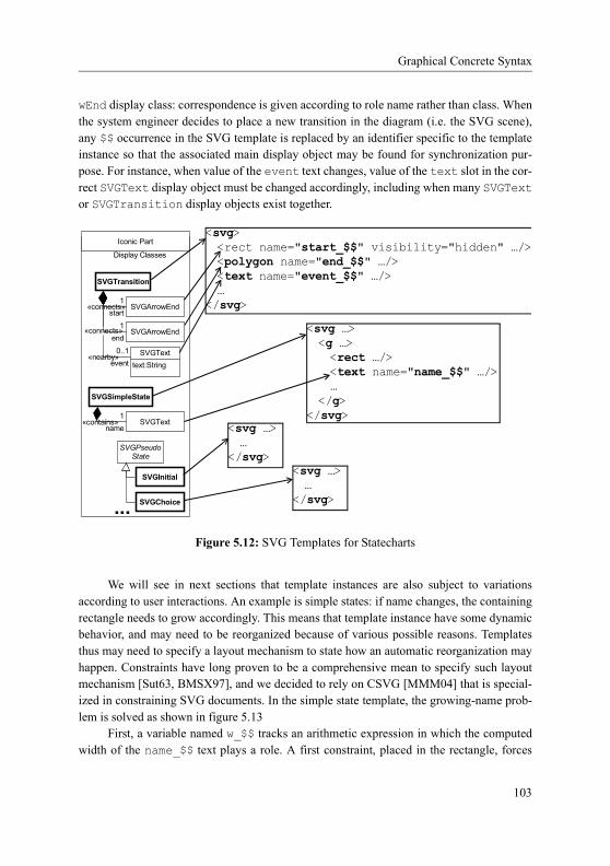
Applying and Customizing LDE
tions defined by the MTL-aspect, e.g., the servantIterfaceName MTL attribute and the initDI MTL method.
A conflict may appear during a class merge if some members in the matching input classes and in the MTL-aspect class have the same name. If the member in the MTL-aspect is an attribute, it will be added as it is, without worrying whether the name of the attribute already exists in the input MTL library, since the rest of the compilation process will detect such a duplicate attribute, if any, and an error will be thrown. For methods, the detected conflict is registered to be solved later.
MTL-aspect developers may refer many MTL classes or MTL methods in a single pattern by relying on "wildcard" facilities, such as "_", which matches any name, or the more sophisticated regular expressions delimited by curly brackets. For instance, in figure A.13 , the class named {Copier$}, matches all input classes whose name ends (denoted by $) with "Copier", and its method {^getTarget(.*)} matches all input methods, defined on the matched input classes, whose name starts (denoted by ^) with "get-Target". As a rule, MTL-aspect developers should not abuse of such constructs in order to add new classes or methods to the output library.
The class merge process, as it is implemented in the MTL weaver, is shown in figure A.14. The libClass represents the input class, and the behaviorClass repre-sents the MTL-aspect class. Please note that the name of the behaviorClass matches the name of the libClass as a precondition for the mergeClass method.
A method conflict may be solved according to some predefined rules. We have identi-fied three kinds of possible rules that prescribe the MTL weaver how to manage the instruc-tions defined by the conflicting method of the MTL-aspect:
• run MTL-aspect instructions at the very beginning of the output method,• run MTL-aspect instructions just before returning from the output method, or• replace input instructions with MTL-aspect instructions in the output method.
It is the responsibility of the MTL-aspect developer to indicate which alternative s/he desires to be chosen for a given method conflict. For this purpose, we defined the mergetag that has to be added on each conflicting method in the MTL-aspect. The three possible values corresponding to the previously described rules are Prepend, Append, and Replace respectively. If a conflict cannot be solved, the weaving process ends in failure.
The instructions in the MTL-aspect method may need to refer to some parameters of the matched input methods. The presence of the boolean tag refactorParameters set to true makes the parameters of the input methods accessible inside the MTL-aspect accord-ing to the names provided in the MTL-aspect method. Moreover, this tag makes the method matching take care of the number of parameters in the input methods rather than just match-ing the names of the methods.
As an example, figure A.13 states that for all input methods whose names start with "getTarget" inside classes whose names end with "Copier", the first parameter, named
157

MTL-Based Syntax for Describing the Weaving Behavior
in the MTL-aspect theSource, must be sent to the console by means of the MTL pre-defined operation toOut. This output must be performed before returning from the modi-fied MTL methods, as stated by the value Append of the merge tag defined for the MTL-aspect method.
As a summary, the list of possible tags that may appear in the definition of an MTL-aspect is provided in figure A.15 The first column gives the name of the tag as it must appear in the MTL-aspect. The second column indicates on which MTL element this tag may be defined. The third column indicates whether the presence of the tag is mandatory or
mergeClass(libClass : BasicMtlASTView::UserClass; behaviorClass : BasicMtlASTView::UserClass) { lo : Standard::Set; // adding attributes if (isNull(behaviorClass.definedAttributes).not()) { foreach (at : BasicMtlASTView::Attribute) in (behaviorClass.definedAttributes) { libClass.appendDefinedAttributes(at); } } // merging operations foreach (bo : BasicMtlASTView::Operation) in (behaviorClass.definedMethods) { lo := matchingOperations(libClass, bo); if (lo.size().[=](0)) { // to be added if (self.canAdd(bo)) { libClass.appendDefinedMethods(bo); } else { bo.name.concat( 'seems to be a pattern; no correspondance found.' ).toOut(); 'ignoring addition to class '.concat(lib-Class.name).toOut(); } } else { // conflict, to be treated later self.operationConflicts := operationConflicts.including( new OperationConflict().init(libClass, lo, bo)); } } }
Figure A.14: MTL Weaver Snippets for Class Merge (mergeClass)
158

Applying and Customizing LDE
optional; default values are indicated for optional tags. The fourth column gives a brief description of the semantics of the possible associated values.
As we showed on some concrete examples, the MTL-aspect developer does not need to have a deep knowledge of the MTL metamodel and its semantics in order to transform an MTL transformation. All s/he needs to know is the MTL syntax and some predefined tags. Moreover, with the current implementation of the MTL weaver, an MTL-aspect is about 10 times smaller (in lines of code) and about 50 times faster to develop than a standard MTL transformation that would achieve the same weaving behavior on another MTL transforma-tion.
Please notice, however, that the MTL weaver and the aspect-oriented support pro-vided are prototypes, so there is still room for refinement and improvement. New constructs could be added in order to address MTL-aspect developer needs and to facilitate as much as possible the development of "reflective" MTL transformations. For instance, it would be very helpful to have a pattern matching for instructions or expressions, e.g., matching all calls to a given method. The pattern we adopted for extending the MTL language with AOP-like constructs would remain nevertheless the same, i.e., extending the language by providing new tags that change the semantics of their base element, just like UML profiles extend the UML.
A.3.4 Running Example
In this part, we consider the weaving of the MTL1-D-Aspect in the simple MTL Copytransformation in order to modify its behavior and make a system distributed by applying
Tag NameBase MTL
ElementPresence Description
rename Library mandatory The name of the output library.
merge Method mandatory if conflict
Prepend to add instructions at the very beginning of the method.Append to add instructions just before returning from the method.Replace to replace initial instruc-tions with MTL-aspect instructions.
refactor-Parameters
Method optional; default value is false
Indicates if the number of parameters has to be considered in the pattern matching, and if parameters have to be intercepted for further use inside MTL-aspect instructions.
Figure A.15: Predefined MTL-Aspect Tags
159
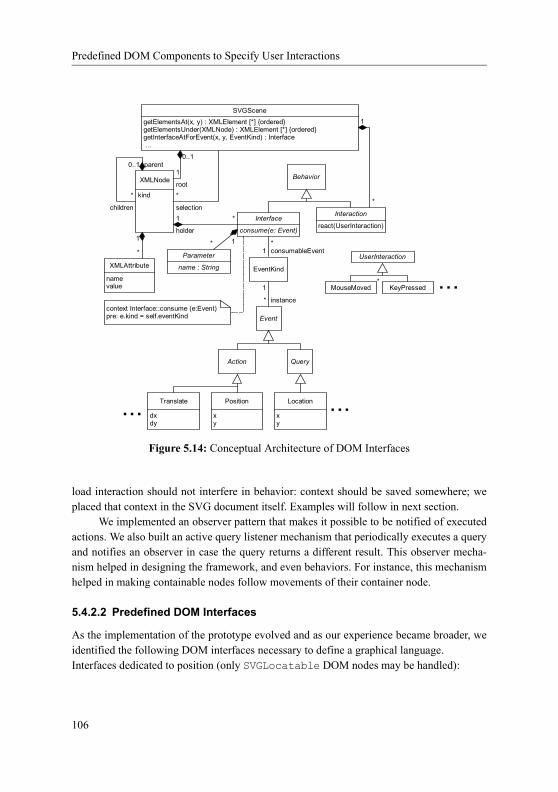
Running Example
the stereotypes defined in the DistributionProfile according to some configuration information. Since the goal is to illustrate the most important principles of the weaving pro-cess, we focus on very small parts of the example.
The input MTL Copy transformation is specialized in copying an input UML 1.4 model to an output UML 1.4 model. Snippets of the transformation are presented in figure A.16. The transformation is located in the MTL library Copy, having two variables, in and out, for referring to the input, and output models respectively. One of the MTL classes of this library is Copier, which defines the getTarget method. This method takes as parameter a UML element srcElt from the in model, and retrieves and returns the cor-responding UML element inside the out model. Another MTL class, extending Copier, is UML14CreatorCopier, which defines the getTargetClass method. This method takes a UML class src in the in model as parameter, and is responsible for creating and returning a UML class in the out model.
We present now two of the modifications that have to be performed in order for the MTL Copy transformation to make a system distributed. The first one is to make an inter-face remotely available, but before doing this we still need to identify the right interface. The solution we considered is to add an attribute, servantIterfaceName, to the MTL Copier class as a placeholder for the name of the interface to be distributed. This attribute is transmitted to the MTL Copier class by means of the new method initDI defined in the MTL1-D-Aspect. The second modification is to display on the console UML elements
library Copy; model in : RepositoryModel;// should be a UML1.4 MetaModel model out : RepositoryModel;// should be a UML1.4 MetaModel class Copier { getTarget(srcElt : in::Core::Element) : out::Core::Element { r : out::Core::Element; ... // compute r return r; } } class UML14CreatorCopier extends Copier { getTargetClass(src : in::Core::Class) : out::Core::Class { r : out::Core::Class; r := new out::Core::Class(); trace(src, r); return r; } }
Figure A.16: Snippets of the Copy Input Library
160
Applying and Customizing LDE
from the in model for which a correspondence in the out model has been requested. A thorough analysis of the complete MTL Copy transformation would clarify that such corre-spondences are only requested when invoking methods whose names start with "getTarget", and which belong to a class whose name ends with "Copier". These modifications are pre-scribed in the MTL1-D-Aspect that was partly presented in figure A.13, where part cor-responded to the first modification, and part to the second one.
The result of weaving the MTL1-D-Aspect in the MTL Copy transformation is shown in figure A.17. Even though we have clearly stated in section A.3.2 that the results of the MTL weaving process are just MTL binaries and Java source files, figure A.17 repre-sents what a pretty printer would produce for the MTL binary. Changes introduced by the MTL-aspect are highlighted by change bars. Since the output MTL library is different from the original MTL Copy library, a renaming has occurred according to the rename tag that was specified on the library definition inside the MTL1-D-Aspect, as shown in figure A.17.
Part of the MTL1-D-Aspect in figure A.13 states that an MTL class named Copier must appear with a servantIterfaceName attribute and an initDI operation in the output library. Even though such an MTL Copier class already exists in the input library, no name conflicts have been found, and therefore member definitions from both the MTL-aspect and the input class are directly added to the MTL Copier output class, as shown by figure A.17 .
The MTL-aspect method defined in part of the MTL1-D-Aspect in figure A.13matches the input methods Copier::getTarget and UML14CreatorCopier::get-TargetClass. Please note that the presence of the refactorParameters tag set to true in the MTL-aspect has made the method matching check that only one parameter is defined for these input methods, parameter that will further on be used as the variable the-Source inside the body of the MTL-aspect method. The tag merge set to Append defined on the MTL-aspect method indicates how possible conflicts should be solved. Since con-flicts have indeed been found, the instructions defined in the MTL-aspect have to be inserted in the output class just before returning from the corresponding reproductions of the input methods in the output class, as part of the output library. To achieve this, we rely on the MTL try-catch-finally statement: instructions of the input method are repro-duced in the try part, and instructions from the MTL-aspect method are reproduced in the finally part, as shown in figure A.17 . In this way, we enforce that instructions from the MTL-aspect method are executed just before returning from the output method, wher-ever an MTL return instruction may appear in the input method. The true value for the refactorParameters tag also instructs the MTL weaver to produce new variables in the output methods according to the parameters defined in the MTL-aspect method that are sup-posed to match parameters from the input methods. These new variables represent place-holders for the values of the parameters of the input methods that were intercepted by the corresponding MTL-aspect method. Applying this rule for the two input methods matching
161

Running Example
library Distribution; model in : RepositoryModel;// should be a UML1.4 MetaModel model out : RepositoryModel;// should be a UML1.4 MetaModel class Copier { servantIterfaceName : Standard::String; initDI(sin : Standard::String) : Copier { self.servantIterfaceName := sin; return self; } getTarget(srcElt : in::Core::Element) : out::Core::Element { r : out::Core::Element; theSource : Standard::ModelElement; theSource := srcElt; // [*] try { ... // compute r return r; } finally { theSource.toOut(); // [*] } } } class UML14CreatorCopier extends Copier { getTargetClass(src : in::Core::Class) : out::Core::Class { theSource : Standard::ModelElement; theSource := src; // [*] try { r : out::Core::Class; r := new out::Core::Class(); trace(src, r); return r; } finally { theSource.toOut(); // [*] } } }
Figure A.17: Snippets of the Distribution Output Library
162

Applying and Customizing LDE
the MTL-aspect method {^getTarget(.*)}, new theSource variables will be added in the corresponding output methods for storing the very input parameters that were previ-ously matched (see figure A.17 [*]).
A.4 Conclusion
An LDE step is mainly composed of an abstraction layer describing the system under study that is improved to reach a more concrete abstraction layer by integrating more information about platform(s) specificities. Regarding current technologies (see chapter 2), an abstrac-tion layer may be a set of models, each one of them being described using a modeling lan-guage defined by an abstract syntax, one or more concrete syntaxes, and semantics. Improvement may be realized by a model transformation expressed in a model transforma-tion language (with abstract syntax, semantics and concrete syntax).
This thesis proposed techniques to describe concrete syntaxes of languages whose abstract syntax is given in the form of a metamodel. Beside this, this appendix underlined the interest for an existing LDE methodology to be "tailorable". We also explored a mean to define such customizations regarding abstract syntaxes and improvements (through trans-formations) when modeling languages and transformation languages proposed an extension mechanism related to profiles. UML and MTL are such languages, so does Java when used with annotations [Jav04].
We explored here such a mean for languages that already include an extension mech-anism both in their abstract syntax and concrete syntax. However, this is only a first step. Indeed, one may need to tailor languages at abstract syntax level (e.g. using higher-order hierarchies), at semantics level, but also at concrete syntax level.[AvSB04]
163

Conclusion
164

Bibliography
Bibliography[AAB+07] Adaptive Ltd., Alcatel, Borland Software Corporation, Computer Associates
International, Inc., Telefonaktiebolaget LM Ericsson, Fujitsu, Hewlett-Pack-ard Company, I-Logix Inc., International Business Machines Corporation, IONA Technologies, Kabira Technologies, Inc., MEGA International, Motorola, Inc., Object Management Group., Oracle Corporation, SOFT-EAM, Telelogic AB, Unisys, and X-Change Technologies Group, LLC, Uni-fied Modeling Language (UML), version 2.1.1, OMG Document formal/07-02-05, February 2007.
[AAR05] Uwe Aßmann, Mehmet Aksit, and Arend Rensink (eds.), Model Driven Architecture, European MDA Workshops: Foundations and Applications, MDAFA 2003 and MDAFA 2004, Twente, The Netherlands, June 26-27, 2003 and Linköping, Sweden, June 10-11, 2004, Revised Selected Papers, Lecture Notes in Computer Science, vol. 3599, Springer, 2005.
[ABB+04] Alcatel, BEA Systems, Inc., BNR Europe Ltd., Borland International, DSTC Pty Ltd, Concept Five Technologies, Digital Equipment Corporation, Eternal Systems, Inc., Expersoft Corporation, FUJITSU LIMITED, Genesis Devel-opment Corporation, Hewlett-Packard Company, HighComm, Highlander Communications, L.C., HyperDesk Corporation, Inprise Corporation, Inter-national Business Machines Corporation, ICL plc, Inprise Corporation, Inter-national Computers, Ltd., IONA Technologies, Ltd., Lockheed Martin Federal Systems, Inc., Lucent Technologies, Inc., Micro Focus Limited, NCR Corporation, NEC Corporation, Netscape Communications Corpora-tion, Nortel Networks, Northern Telecom Corporation, Novell USG, Object Design, Inc., Object Management Group, Inc., Objective Interface Systems, Inc., Object-Oriented Concepts, Inc., Oracle Corporation, PeerLogic, Inc., Siemens Nixdorf Informationssysteme AG, Sun Microsystems, Inc., Sun-Soft, Inc., Sybase, Inc., Telefnica Investigacin y Desarrollo S.A. Uniper-sonal, TIBCO, Inc., Tri-Pacific Software, Inc., and Visual Edge Software, Ltd., Common Object Request Broker Architecture: Core specification, v.3.0.3, OMG Document formal/2004-03-12, March 2004.
[ABF+06] Adaptive Ltd., Boldsoft, France Telecom, International Business Machines Corporation, IONA Technologies, and Object Management Group, Object Constraint Language specification, v2.0, OMG Document formal/06-05-01, May 2006.
165

Bibliography
[ABH+00] AT&T, BNR, Hewlett-Packard, Object Management Group, Inc., and Sun Soft, Trading Object Service specification, v1.0, OMG Document formal/2004-03-12, May 2000.
[Abr96] J.-R. Abrial, The B-book: assigning programs to meanings, Cambridge Uni-versity Press, New York, NY, USA, 1996.
[ACC+06] Adaptive, Ceira Technologies, Inc., Compuware Corporation, Data Access Technologies, Inc., DSTC, Gentleware, Hewlett-Packard, International Busi-ness Machines, IONA, Object Management Group, MetaMatrix, Softeam, SUN, Telelogic AB, and Unisys, Meta-Object Facility (MOF) core, v2.0, OMG Document formal/2006-01-01, January 2006.
[ACD+05] Adaptive, Compuware Corporation, DSTC, Hewlett-Packard, International Business Machines, IONA, Object Management Group, SUN, and Unisys, XML Metadata Interchange (XMI v2.1), OMG Document formal/05-09-01, September 2005.
[ADF+05] Alcatel, DMR Consulting, Fujitsu Limited, International Business Machines Corporation, Q-Labs, Rational Software Corporation, SOFTEAM, and Uni-sys Corporation, Software Process Engineering Metamodel, v1.1, OMG Document formal/05-01-06, January 2005.
[ADG+06] Adaptive, DaimlerChrysler AG, Gentleware AG, IBM Rational Software, Sun Microsystems, and Telelogic AB, Diagram Interchange specification, v1.0, OMG Document formal/06-04-04, April 2006.
[ADvSP04] João Paulo A. Almeida, Remco M. Dijkman, Marten van Sinderen, and Luis Ferreira Pires, On the Notion of Abstract Platform in MDA Develop-ment, In Akehurst et al. [AvSB04], pp. 253–263.
[AK02] Colin Atkinson and Thomas Kühne, The role of meta-modeling in MDA, Workshop in Software Model Engineering (WISME@UML) (Dresden, Ger-many), October 2002.
[ALPT03] Marcus Alanen, Johan Lilius, Ivan Porres, and Dragos Truscan, Realizing a Model Driven Engineering Process, Tech. Report 565, TUCS - Turku Centre for Computer Science, Turku, Finland, November 2003.
[ALSU06] Alfred V. Aho, Monica S. Lam, Ravi Sethi, and Jeffrey D. Ullman, Compil-ers: Principles, Techniques, and Tools (2nd Edition), Addison Wesley, August 2006.
[And96] Marc Andries, Graph Rewrite Systems and Visual Database Languages, Ph.D. thesis, Universität Bremen, 1996.
166

Bibliography
[AP04] Marcus Alanen and Ivan Porres, A Relation Between Context-Free Gram-mars and Meta Object Facility Metamodels, Tech. Report 606, TUCS - Turku Centre for Computer Science, Turku, Finland, March 2004.
[Apa] Apache Foundation - XML Graphics Project, Batik SVG toolkit, http://xml-graphics.apache.org/batik/.
[AvSB04] David H. Akehurst, Marten van Sinderen, and Barrett R. Bryant (eds.), 8th international enterprise distributed object computing conference (EDOC 2004), 20-24 september 2004, Monterey, California, USA, proceedings, IEEE Computer Society, 2004.
[BA04] Kent Beck and Cynthia Andres, Extreme Programming Explained: Embrace Change (2nd Edition), Addison-Wesley Professional, 2004.
[Baa06] Thomas Baar, Correctly Defined Concrete Syntax for Visual Modeling Lan-guages, In Nierstrasz et al. [NWHR06], pp. 111–125.
[Bar98] Roswitha Bardohl, GENGED - A Generic Graphical Editor for Visual Lan-guages Based on Algebraic Graph Grammars, VL, 1998, pp. 48–55.
[BBG+60] J. W. Backus, F. L. Bauer, J. Green, C. Katz, J. McCarthy, A. J. Perlis, H. Rutishauser, K. Samelson, B. Vauquois, J. H. Wegstein, A. van Wijn-gaarden, and M. Woodger, Report on the algorithmic language ALGOL 60, Commun. ACM 3 (1960), no. 5, 299–314.
[BD99] Adolf-Peter Bröhl and Wolfgang Dröschel, Das V-Modell. Der Standard in der Softwareentwicklung mit Praxisleitfaden (Auflage: 2), Oldenbourg Ver-lag, 1999.
[BDII02] BEA Systems, DSTC, Iona Technologies Ltd., and Inprise, Naming Service specification, v1.3, OMG Document formal/2004-10-03, September 2002.
[BDJ+03] Jean Bézivin, Grégoire Dupé, Frédéric Jouault, Gilles Pitette, and Jamal Eddine Rougui, First experiments with the ATL model transformation language: Transforming XSLT into XQuery, OOPSLA 2003 Workshop (Anaheim, California), 2003.
[Bea06] Olivier Beaudoux, DoPIdom: une approche de l’interaction et de la collabo-ration centrée sur les documents, IHM ’06: Proceedings of the 18th interna-tional conference on Association Francophone d’Interaction Homme-Machine (New York, NY, USA), ACM Press, 2006, pp. 19–26.
[BEdLT04] Roswitha Bardohl, Hartmut Ehrig, Juan de Lara, and Gabriele Taentzer, Integrating Meta-modelling Aspects with Graph Transformation for Efficient
167

Bibliography
Visual Language Definition and Model Manipulation, FASE (Michel Wer-melinger and Tiziana Margaria, eds.), Lecture Notes in Computer Science, vol. 2984, Springer, 2004, pp. 214–228.
[Ben86] Jon Bentley, Programming pearls: little languages, Commun. ACM 29 (1986), no. 8, 711–721.
[BGdL06] Paolo Bottoni, Esther Guerra, and Juan de Lara, Metamodel-based definition of interaction with visual environments, MoDELS’06 Workshop on Model Driven Development of Advanced User Interfaces (MDDAUI’06 at MoD-ELS’06), CEUR Workshop Proceedings, vol. 214, 2006.
[BJPW99] Antoine Beugnard, Jean-Marc Jézéquel, Noël Plouzeau, and Damien Wat-kins, Making Components Contract Aware, Computer 32 (1999), no. 7, 38–45.
[BLP04] Fabrice Bouquet, Bruno Legeard, and Fabien Peureux, CLPS-B - A con-straint solver to animate a B specification, STTT 6 (2004), no. 2, 143–157.
[BM03] Peter Braun and Frank Marschall, Transforming Object Oriented Models with BOTL, Electr. Notes Theor. Comput. Sci. 72 (2003), no. 3, 103–117.
[BMSX97] Alan Borning, Kim Marriott, Peter J. Stuckey, and Yi Xiao, Solving Linear Arithmetic Constraints for User Interface Applications, ACM Symposium on User Interface Software and Technology, 1997, pp. 87–96.
[Boh07] Matthias Bohlen, AndroMDA, http://www.andromda.org/, 2007.
[Bos00] Jan Bosch, Design and use of software architectures: adopting and evolving a product-line approach, ACM Press/Addison-Wesley Publishing Co., New York, NY, USA, 2000.
[BPSM+06] Tim Bray, Jean Paoli, C.-M. Sperberg-McQueen, Eve Maler, Francois Yer-geau, and John Cowan, Extensible Markup Language (XML 1.1 - second edition), World Wide Web Consortium, August 2006.
[BRTK] Marko Boger, Jason Robbins, Linus Tolke, and Markus Klink, ArgoUML), http://argouml.tigris.org/.
[CBR03] Adrian Colyer, Gordon Blair, and Awais Rashid, Managing Complexity in Middleware, The Second AOSD Workshop on Aspects, Components, and Patterns for Infrastructure Software (ACP4IS) (Yvonne Coady, Eric Eide, and David H. Lorenz, eds.), March 2003.
[CCD+06] Codagen Technologies Corp, Compuware, DSTC, France Telecom, IBM, INRIA, Interactive Objects, Kings College London, Object Management
168

Bibliography
Group, Softeam, Sun Microsystems, Tata Consultancy Services, Thales, TNI-Valiosys, University of Paris VI, and University of York, Meta Object Facility (MOF) 2.0 Query/View/Transformation Specification, OMG Docu-ment ptc/05-11-01, October 2006, MOF QVT Final Adopted Specification.
[CDP04] Gennaro Costagliola, Vincenzo Deufemia, and Giuseppe Polese, A frame-work for modeling and implementing visual notations with applications to software engineering, ACM Trans. Softw. Eng. Methodol. 13 (2004), no. 4, 431–487.
[CESW05] Tony Clark, Andy Evans, Paul Sammut, and James Willans, Applied Meta--modelling: A Foundation for Language-Driven Development, 2005.
[CH06] K. Czarnecki and S. Helsen, Feature-based survey of model transformation approaches, IBM Syst. J. 45 (2006), no. 3, 621–645.
[Cho56] Noam Chomsky, Three models for the description of language, IEEE Trans-actions on Information Theory 2 (1956), no. 3, 113–124.
[CIM+06] Compuware Corporation, Interactive Objects Software GmbH, Mentor Graphics Corporation, Object Management Group, Pathfinder Solutions, SINTEF, Softeam, and Tata Consultancy Services, MOF Models to Text Transformation Language final adopted specification, OMG Document ptc/06-11-01, November 2006.
[CLOP02] Gennaro Costagliola, Andrea De Lucia, Sergio Orefice, and Giuseppe Polese, A Classification Framework to Support the Design of Visual Lan-guages, J. Vis. Lang. Comput. 13 (2002), no. 6, 573–600.
[CM03] Sitt Sen Chok and Kim Marriott, Automatic generation of intelligent dia-gram editors, ACM Trans. Comput.-Hum. Interact. 10 (2003), no. 3, 244–276.
[Dal05] Christopher J Daly, AST framework generation with Gymnast, Tech Exchange Panel: Language Toolkits. EclipseCON, 2005.
[Dav03] James Davis, GME: the generic modeling environment., OOPSLA Compan-ion (Ron Crocker and Guy L. Steele Jr., eds.), ACM, 2003, pp. 82–83.
[DDF+04] Data Access Technologies, DSTC Pty Ltd, France Telecom, IBM, IONA Technologies, Object Management Group, Inc., Open-IT, and Unisys, Human-Usable Textual Notation, v1.0, OMG Document formal/04-08-01, August 2004.
169

Bibliography
[DDG+02] Data Access Corporation, DSTC Pty Ltd, Genesis Development Corpora-tion, Telelogic AB, and UBS AG, UML profile for CORBA specification, v.1.0, OMG Document formal/02-04-01, April 2002.
[dLV02] Juan de Lara and Hans Vangheluwe, Using AToM3 as a Meta-Case Tool, Proceedings of the 4th International Conference on Enterprise Information Systems (ICEIS), 2002, pp. 642–649.
[DMNS97] Serge Demeyer, Theo Dirk Meijler, Oscar Nierstrasz, and Patrick Steyaert, Design Guidelines for ’Tailorable Frameworks’, Commun. ACM 40 (1997), no. 10, 60–64.
[DV02] Péter Domokos and Dániel Varró, An Open Visualization Framework for Metamodel-Based Modeling Languages, Electr. Notes Theor. Comput. Sci. 72 (2002), no. 2, 69–78.
[Ecl] Eclipse Consortium, Eclipse Graphical Editing Framework (GEF), http://www.eclipse.org/gef.
[Ecl05] Eclipse, Eclipse Modeling Framework (EMF), December 2005.
[Ecl06] Eclipse, Graphical Modeling Framework (GMF), June 2006.
[EEHT05] Karsten Ehrig, Claudia Ermel, Stefan Hänsgen, and Gabriele Taentzer, Gen-eration of visual editors as eclipse plug-ins, ASE (David F. Redmiles, Tho-mas Ellman, and Andrea Zisman, eds.), ACM, 2005, pp. 134–143.
[EEKR99] H. Ehrig, G. Engels, H.-J. Kreowski, and G. Rozenberg, Handbook of graph grammars and computing by graph transformation, World Scientific, 1999.
[Ern03] Erik Ernst, Higher-Order Hierarchies, ECOOP 2003 - Object-Oriented Pro-gramming, 17th European Conference on (Luca Cardelli, ed.), LNCS, vol. 2743, Springer, July 2003, pp. 303–328.
[ESW+05] Andy Evans, Paul Sammut, James S. Willans, Alan Moore, and Girish Maskeri, A Unified Superstructure for UML, Journal of Object Technology 4 (2005), no. 1, 165–182.
[FB05] Frédéric Fondement and Thomas Baar, Making Metamodels Aware of Con-crete Syntax, European Conference on Model Driven Architecture (ECMDA), Lecture Notes in Computer Science, vol. 3748, 2005, pp. 190 – 204.
[FBBO99] M. Fowler, K. Beck, J. Brant, and W.F. Opdyke, Refactoring: Improving the Design of Existing Code, Addison-Wesley, 1999.
170

Bibliography
[Fle06] Franck Fleurey, Langage et méthode pour une ingénierie des modèles fiable, Ph.D. thesis, Université de Rennes 1, October 2006.
[Fon06] Choong Koon Fong, Quick Start Guide to MDA, A Primer to Model-Driven Architecture Using Borland Together Technologies, Borland White Paper, September 2006.
[fRiCSI05] French National Institute for Research in Computer Science and Control (INRIA), Model transformation language (MTL), http://modelware.inria.fr/, 2005.
[FS04] Frédéric Fondement and Raul Silaghi, Defining Model Driven Engineering Processes, Third International Workshop in Software Model Engineering (WiSME), held at the 7th International Conference on the Unified Modeling Language (UML), 2004.
[FSGM06] Frédéric Fondement, Rémi Schnekenburger, Sébastien Gérard, and Pierre-Alain Muller, Metamodel-Aware Textual Concrete Syntax Specification, Tech. Report LGL-REPORT-2006-005, École Polytechnique Fédérale de Lausanne (EPFL), 2006.
[GBNT01] Jeff Gray, Ted Bapty, Sandeep Neema, and James Tuck, Handling crosscut-ting constraints in domain-specific modeling, Communications of the ACM 44 (2001), no. 10, 87–93.
[Göt82] Herbert Göttler, Attributed graph grammars for graphics, Graph-Grammars and Their Application to Computer Science (Hartmut Ehrig, Manfred Nagl, and Grzegorz Rozenberg, eds.), Lecture Notes in Computer Science, vol. 153, Springer, 1982, pp. 130–142.
[GRS06] Angelo Gargantini, Elvinia Riccobene, and Patrizia Scandurra, Deriving a textual notation from a metamodel: an experience on bridging modelware and grammarware, European Workshop on Milestones, Models and Map-pings for Model-Driven Architecture - European Conference on Model Driven Architecture (3M4MDA), July 2006.
[GSCK04] Jack Greenfield, Keith Short, Steve Cook, and Stuart Kent, Software Facto-ries: Assembling Applications with Patterns, Models, Frameworks, and Tools, Wiley, August 2004.
[GSR05] Leif Geiger, Christian Schneider, and Carsten Reckord, Template and model-based code generation for MDA-Tools, 3rd International Fujaba Days (IFD05), 2005.
171

Bibliography
[Har87] David Harel, Statecharts: A Visual Formulation for Complex Systems, Sci-ence of Computer Programming 8 (1987), no. 3, 231–274.
[HHW+04] Arnaud Le Hors, Philippe Le Hégaret, Lauren Wood, Gavin Nicol, Jonathan Robie, Mike Champion, and Steve Byrne, Document Object Model (DOM) level 3 core specification, World Wide Web Consortium, April 2004.
[Hil02] Stéphane Hillion, Koala DynamicJava, http://koala.ilog.fr/djava/index.html, June 2002.
[Hof79] Douglas R. Hofstadter, Godel, Escher, Bach: An Eternal Golden Braid, Basic Books, Inc., New York, NY, USA, 1979.
[Hon92] Honeywell, DOME guide, http://www.htc.honeywell.com/dome/, 1992.
[Hon05] Fabrice Hong, Provide behaviour to XML-SVG, Bachelor Semester Project, École Polytechnique Fédérale de Lausanne (EPFL), 2005.
[HR04] David Harel and Bernhard Rumpe, Meaningful Modeling: What’s the Semantics of "Semantics"?, Computer 37 (2004), no. 10, 64–72.
[HRS02] David Hearnden, Kerry Raymond, and Jim Steel, Anti-Yacc: MOF-to-Text, Proceedings of the Sixth International Enterprise Distributed Onject Com-puting Conference (EDOC’02) (Washington, DC, USA), IEEE Computer Society, 2002, p. 200.
[Iiv96] Juhani Iivari, Why Are Case Tools Not Used?, Commun. ACM 39 (1996), no. 10, 94–103.
[Int01] International Organization for Standardization, Information Technology - Syntactic Metalanguage - Extended BNF, ISO/IEC 14977, August 2001.
[ISO05] ISO/IEC, Meta-Object Facility (MOF) v1.4.1, OMG Document formal/05-05-05, ISO PAS 19502 standard, July 2005.
[J03] Jean-Marc Jézéquel, Model-Driven Engineering: Basic Principles and Chal-lenges, Invited Presentation at Formal Methods for Components and Objects (FMCO’03), November 2003.
[Jac02] Daniel Jackson, Alloy: a lightweight object modelling notation, Software Engineering and Methodology 11 (2002), no. 2, 256–290.
[Jac04] Ivar Jacobson, Object-Oriented Software Engineering: A Use Case Driven Approach, Addison Wesley Longman Publishing Co., Inc., Redwood City, CA, USA, 2004.
172

Bibliography
[Jav02] Java Community Process, Java(TM) Metadata Interface API specification 1.0 final release, JSR-000040, June 2002.
[Jav04] Java Community Process, A metadata facility for the Java(TM) program-ming language, JSR-000175, September 2004.
[JBK06] Frédéric Jouault, Jean Bézivin, and Ivan Kurtev, TCS: a DSL for the specifi-cation of textual concrete syntaxes in model engineering, GPCE (Stan Jarza-bek, Douglas C. Schmidt, and Todd L. Veldhuizen, eds.), ACM, 2006, pp. 249–254.
[JM97] Jean-Marc Jézéquel and Bertrand Meyer, Design by Contract: The Lessons of Ariane, IEEE Computer 30 (1997), no. 1, 129–130.
[JN05] Dean Jackson and Craig Northway, Scalable Vector Graphics (SVG) Full 1.2 specification, World Wide Web Consortium, Working Draft WD-SVG12-20050413, April 2005.
[Joh79] Steven C. Johnson, Yacc: Yet Another Compiler Compiler, UNIX Program-mer’s Manual (New York, NY, USA), vol. 2, Holt, Rinehart, and Winston, New York, NY, USA, 1979, pp. 353–387.
[Jon90] Chris Jones, An example-based introduction to graph grammars for model-ing, Proceedings of the Twenty-Third Annual Hawaii International Confer-ence on System Sciences, vol. iii, 1990, pp. 433–442.
[KBA02] Ivan Kurtev, Jean Bézivin, and Mehmet Aksit, Technical spaces: An initial appraisal, CoopIS, DOA 2002 Federated Conferences, Industrial track, 2002.
[KBC04] Audris Kalnins, Janis Barzdins, and Edgars Celms, Model Transformation Language MOLA, In Aßmann et al. [AAR05], pp. 62–76.
[KCH+90] Kyo C. Kang, Sholom G. Cohen, James A. Hess, William E. Novak, and Spencer A. Peterson, Feature-Oriented Domain Analysis (FODA) Feasibility Study, Tech. Report CMU/SEI-90-TR-21, Software Engineering Institute, Pittsburgh, U.S.A., November 1990.
[Ken02] Stuart Kent, Model Driven Engineering, IFM (Michael J. Butler, Luigia Petre, and Kaisa Sere, eds.), Lecture Notes in Computer Science, vol. 2335, Springer, 2002, pp. 286–298.
[KHH+01] Gregor Kiczales, Erik Hilsdale, Jim Hugunin, Mik Kersten, Jeffrey Palm, and William G. Griswold, Getting started with ASPECTJ, Commun. ACM 44 (2001), no. 10, 59–65.
173

Bibliography
[KLM+97] Gregor Kiczales, John Lamping, Anurag Mendhekar, Chris Maeda, Cristina Videira Lopes, Jean-Marc Loingtier, and John Irwin, Aspect-Ori-ented Programming, ECOOP, 1997, pp. 220–242.
[KMB+96] Richard B. Kieburtz, Laura McKinney, Jeffrey M. Bell, James Hook, Alex Kotov, Jeffrey Lewis, Dino Oliva, Tim Sheard, Ira Smith, and Lisa Walton, A Software Engineering Experiment in Software Component Generation, ICSE, 1996, pp. 542–552.
[Knu68] Donald E. Knuth, Semantics of Context-Free Languages, Mathematical Sys-tems Theory 2 (1968), no. 2, 127–145.
[KP02] Steven Kelly and Risto Pohjonen, Domain-Specific Modelling for Cross-Platform Product Families, ER (Workshops) (Stefano Spaccapietra, Salvatore T. March, and Yahiko Kambayashi, eds.), Lecture Notes in Com-puter Science, vol. 2503, Springer, 2002, pp. 182–194.
[Kru03] Philippe Kruchten, The Rational Unified Process: An Introduction, Addison-Wesley Longman Publishing Co., Inc., Boston, MA, USA, 2003.
[KSLB03] Gabor Karsai, Janos Sztipanovits, Ákos Lédeczi, and Ted Bapty, Model-integrated development of embedded software, Proceedings of the IEEE 91 (2003), no. 1, 145–164.
[KW03] Anneke Kleppe and Jos Warmer, Do MDA Transformations Preserve Mean-ing? An investigation into preserving semantics, MDA Workshop (Andy Evans, Paul Sammut, and James S Willans, eds.), November 2003, pp. 13–22.
[LBM+01] Ákos Lédeczi, Arpad Bakay, Miklos Maroti, Péter Völgyesi, Greg Nord-strom, Jonathan Sprinkle, and Gabor Karsai, Composing Domain-Specific Design Environments, IEEE Computer 34 (2001), no. 11, 44–51.
[Leh80] Meir M. Lehman, On understanding laws, evolution, and conservation in the large-program life cycle, Journal of Systems and Software 1 (1980), 213–221.
[LHBJ05] Denivaldo Lopes, Slimane Hammoudi, Jean Bézivin, and Frédéric Jouault, Generating Transformation Definition from Mapping Specification: Applica-tion to Web Service Platform, CAiSE (Oscar Pastor and João Falcão e Cunha, eds.), Lecture Notes in Computer Science, vol. 3520, Springer, 2005, pp. 309–325.
174

Bibliography
[MB05] Slavisa Markovic and Thomas Baar, Refactoring OCL annotated UML class diagrams, MoDELS (Lionel C. Briand and Clay Williams, eds.), Lecture Notes in Computer Science, vol. 3713, Springer, 2005, pp. 280–294.
[MB06] Slavisa Markovic and Thomas Baar, An OCL Semantics Specified with QVT, In Nierstrasz et al. [NWHR06], pp. 661–675.
[MCF03] Stephen J. Mellor, Anthony N. Clark, and Takao Futagami, Guest Editors’ Introduction: Model-Driven Development, IEEE Software 20 (2003), no. 5, 14–18.
[MFF+06] Pierre-Alain Muller, Franck Fleurey, Frédéric Fondement, Michel Hassen-forder, Rémi Schneckenburger, Sébastien Gérard, and Jean-Marc Jézéquel, Model Driven Analysis and Synthesis of Concrete Syntax, Models/UML 2006, LNCS, vol. 4199, 2006, pp. 98–110.
[MFJ05] Pierre-Alain Muller, Franck Fleurey, and Jean-Marc Jézéquel, Weaving Exe-cutability into Object-Oriented Meta-languages, International Conference on Model Driven Engineering Languages and Systems (MoDELS), LNCS, vol. 3713, Springer, October 2005, pp. 264–278.
[MFV+05] Pierre-Alain Muller, Franck Fleurey, Didier Vojtisek, Zoé Drey, Damien Pol-let, Frédéric Fondement, Philippe Studer, and Jean-Marc Jézéquel, On Exe-cutable Meta-Languages applied to Model Transformations, Model Transformations In Practice Workshop, October 2005.
[MH05] Pierre-Alain Muller and Michel Hassenforder, HUTN as a bridge between modelware and grammarware, WISME Workshop, MODELS / UML’2005, 2005.
[Min02] Mark Minas, Concepts and realization of a diagram editor generator based on hypergraph transformation, Sci. Comput. Program. 44 (2002), no. 2, 157–180.
[MM03] Jishnu Mukerji and Joaquin Miller, MDA guide, v1.0.1, OMG Document omg/03-06-01, June 2003.
[MMM04] Cameron L. McCormack, Kim Marriott, and Bernd Meyer, Constraint SVG, WWW Alt. ’04: Proceedings of the 13th international World Wide Web con-ference on Alternate track papers & posters (New York, NY, USA), ACM Press, 2004, pp. 310–311.
[MSFB05] Pierre-Alain Muller, Philippe Studer, Frédéric Fondement, and Jean Bézivin, Platform independent Web application modeling and development with Netsilon, Software and System Modeling 4 (2005), no. 4, 424–442.
175

Bibliography
[MTAL98] Stephen J. Mellor, Stephen R. Tockey, Rodolphe Arthaud, and Philippe Leb-lanc, An Action Language for UML: Proposal for a Precise Execution Semantics, UML (Jean Bézivin and Pierre-Alain Muller, eds.), Lecture Notes in Computer Science, vol. 1618, Springer, 1998, pp. 307–318.
[MVC03] Esperanza Marcos, Belén Vela, and José Maria Cavero, A Methodological Approach for Object-Relational Database Design using UML, Software and System Modeling 2 (2003), no. 1, 59–75.
[Nag76] M. Nagl, Formal Languages of Labelled Graphs, Computing 16 (1976), no. 1–2, 113–137.
[Net05] Java metamodel, http://java.netbeans.org/, November 2005.
[NFTJ06] Clémentine Nebut, Franck Fleurey, Yves Le Traon, and Jean-Marc Jézéquel, Automatic Test Generation: A Use Case Driven Approach, IEEE Transac-tions on Software Engineering 32 (2006), no. 3, 140–155.
[NWHR06] Oscar Nierstrasz, Jon Whittle, David Harel, and Gianna Reggio (eds.), Model Driven Engineering Languages and Systems, 9th International Con-ference, MoDELS 2006, Genova, Italy, October 1-6, 2006, Proceedings, Lecture Notes in Computer Science, vol. 4199, Springer, 2006.
[Obe07] Obeo, Acceleo, http://www.acceleo.org/, 2007.
[Par72] David Lorge Parnas, On the Criteria To Be Used in Decomposing Systems into Modules, Commun. ACM 15 (1972), no. 12, 1053–1058.
[Par05] Terence Parr, ANother Tool for Language Recognition (ANTLR), 2005.
[Poh03] Risto Pohjonen, Boosting Embedded Systems Development with Domain-Specific Modeling, RTC Magazine (2003), 57–61.
[Por03] Ivan Porres, A Toolkit for Model Manipulation, Springer International Jour-nal on Software and Systems Modeling 2 (2003), no. 4, 370–389.
[PQ95] Terence J. Parr and Russell W. Quong, ANTLR: A predicated-LL(k) parser generator, Software - Practice and Experience 25 (1995), no. 7, 789–810.
[RH06] Fabien Rohrer and Francois Helg, Synchronization between display objects and representation templates in graphical language construction, Bachelor Semester Project, École Polytechnique Fédérale de Lausanne (EPFL), 2006.
[RM07] Romain Rouvoy and Philippe Merle, Un langage de description et de vérifi-cation de motifs d’architecture : Fractal ADL, LMO (Isabelle Borne, Xavier
176

Bibliography
Crégut, Sophie Ebersold, and Frédéric Migeon, eds.), Hermès Lavoisier, 2007, pp. 49–64.
[Sch94] Andy Schürr, Specification of Graph Translators with Triple Graph Gram-mars, WG (Ernst W. Mayr, Gunther Schmidt, and Gottfried Tinhofer, eds.), Lecture Notes in Computer Science, vol. 903, Springer, 1994, pp. 151–163.
[Sch06] Douglas C. Schmidt, Guest Editor’s Introduction: Model-Driven Engineer-ing, IEEE Computer 39 (2006), no. 2, 25–31.
[Sch07] Markus Scheidgen, Textual Editing Framework, http://www2.informatik.hu-berlin.de/sam/meta-tools/tef/, August 2007.
[SFS04a] Raul Silaghi, Frédéric Fondement, and Alfred Strohmeier, Towards an MDA-Oriented UML Profile for Distribution, In Akehurst et al. [AvSB04], pp. 227–239.
[SFS04b] Raul Silaghi, Frédéric Fondement, and Alfred Strohmeier, "Weaving" MTL Model Transformations, In Aßmann et al. [AAR05], pp. 123–138.
[Sil06] Raul Silaghi, Aspect-Oriented Model-Driven Engineering of Middleware-Mediated Distributed Systems, Ph.D. thesis, École Polytechnique Fédérale de Lausanne (EPFL), 2006.
[SK97] Janos Sztipanovits and Gabor Karsai, Model-Integrated Computing, IEEE Computer 30 (1997), no. 4, 110–111.
[SK03] Shane Sendall and Wojtek Kozaczynski, Model Transformation: The Heart and Soul of Model-Driven Software Development, IEEE Software 20 (2003), no. 5, 42–45.
[SKB+95] Janos Sztipanovits, Gabor Karsai, Csaba Biegl, Ted Bapty, Ákos Lédeczi, and Amit Misra, MULTIGRAPH: an architecture for model-integrated com-puting, ICECCS, IEEE Computer Society, 1995, pp. 361–368.
[SS99] Shane Sendall and Alfred Strohmeier, UML Based Fusion Analysis Applied to a Bank Case Study, UML (Robert B. France and Bernhard Rumpe, eds.), Lecture Notes in Computer Science, vol. 1723, Springer, 1999, pp. 278–291.
[SS03] Raul Silaghi and Alfred Strohmeier, Integrating CBSE, SoC, MDA, and AOP in a Software Development Method, EDOC, IEEE Computer Society, 2003, pp. 136–146.
[SS05] Raul Silaghi and Alfred Strohmeier, Parallax, or Viewing Designs Through a Prism of Middleware Platforms, HICSS, IEEE Computer Society, 2005.
177

Bibliography
[Sun05] Sun Microsystems, Metadata repository (MDR), December 2005.
[Sut63] Ivan E. Sutherland, Sketchpad, A Man-Machine Graphical Communication System, Outstanding Dissertations in the Computer Sciences, Garland Pub-lishing, New York, 1963.
[Szy02] Clemens Szyperski, Component Software: Beyond Object-Oriented Pro-gramming, Addison-Wesley Longman Publishing Co., Inc., Boston, MA, USA, 2002.
[TJ07] Emina Torlak and Daniel Jackson, Kodkod: A Relational Model Finder, TACAS (Orna Grumberg and Michael Huth, eds.), Lecture Notes in Com-puter Science, vol. 4424, Springer, 2007.
[VBBJ06] Eric Vépa, Jean Bézivin, Hugo Brunelière, and Frédéric Jouault, Measuring Model Repositories, Proceedings of the Model Size Metrics Workshop at the MoDELS/UML 2006 conference, Genova, Italy, 2006.
[vDKV00] Arie van Deursen, Paul Klint, and Joost Visser, Domain-Specific Languages: An Annotated Bibliography, SIGPLAN Notices 35 (2000), no. 6, 26–36.
[VJ04] Didier Vojtisek and Jean-Marc Jézéquel, MTL and umlaut NG - engine and framework for model transformation, ERCIM News 58 (2004), 46–47.
[Voe06a] Markus Voelter, oAW 4 introduction and overview, http://www.eclipse.org/gmt/oaw/, August 2006.
[Voe06b] Markus Voelter, oAW 4 xText - a framework for textual dsls, http://www.eclipse.org/gmt/oaw/, October 2006.
[Voj04] Didier Vojtisek, BasicMTL realization guide, Tech. report, Institut National de Recherche en Informatique et en Automatique (INRIA), February 2004.
[VPF+06] F. Vernadat, Christian Percebois, Patrick Farail, R. Vingerhoeds, Alain Ros-signol, Jean-Pierre Talpin, and David Chemouil, The TOPCASED Project - A Toolkit in OPen-source for Critical Applications and SystEm Develop-ment, Data Systems In Aerospace (DASIA), Berlin, Germany, 22/05/2006-25/05/2006 (http://www.esa.int/publications), European Space Agency (ESA Publications), May 2006.
[VS06] Markus Völter and Thomas Stahl, Model-Driven Software Development, Wiley, 2006.
[ZG03] Paul Ziemann and Martin Gogolla, An OCL Extension for Formulating Tem-poral Constraints, Tech. Report 1/03, Universität Bremen, 2003.
178

Curriculum Vitae
Curriculum Vitae
Frédéric Fondement
Education
1997 University degree of technology (DUT) in electrical engineering and indus-trial data processing (GEII) with emphasis in electrical engineering - Belfort / France.
2000 Engineering degree in control engineering and industrial data processing from the École Supérieure des Sciences Appliquées pour l'Ingénieur de Mul-house (ESSAIM - now ENSISA) / France.
2001 Diploma in technological research (DRT) GEII from the Upper Alsace Uni-versity entitled "Development of Components for an UML Virtual Machine"- Mulhouse / France.
Research and Professional Experience
2001 Engineering internship for ObjeXion Software - Development of an OCL interpreter for an UML virtual machine (ObjeXion Facsimile).
2001 - 2002 Software engineer for ObjeXion Software - Development and support for a model-driven web application generator (Netsilon [MSFB05]) - Vieux-Thann / France.
2003 Research and development engineer at the French National Institute of Research in Computer Science and Control (INRIA / IRISA) - Model Trans-formation Language (MTL [VJ04]) - Rennes / France.
2004 - 2007 Ph.D. candidate at the Software Engineering Laboratory (LGL) of the École Polytechnique Fédérale de Lausanne (EPFL) in the field of model driven engineering with special interest in concrete syntax modeling - Lausanne / Switzerland.
2007 - 2008 Teaching and research assistant at the Upper Alsace University - Mulhouse / France
PC member Ingénierie Dirigée par les Modèles (IDM) 2005 and 2006
Reviewer Model Driven Software Development Software and Systems Modeling (SoSyM), IET Software, WWW Journal Models/UML 2005, VL-HCC 2005, UML 2003, UML 2001, UML 2000
179

Frédéric Fondement
Teaching
2004 - 2005 Assistant of the Software Engineering Project for 3rd year computer science students.
2005 - 2006 Supervision of 3rd year semester projects entitled "Provide Behaviour to XML / SVG" [Hon05] and "Synchronization between display objects and representation templates in graphical language construction" [RH06].
Publications
[BMFS06] Thomas Baar, Slavisa Markovic, Frédéric Fondement, and Alfred Strohm-eier, Definition and correct refinement of operation specifications., Research Results of the DICS Program (Jürg Kohlas, Bertrand Meyer, and André Schiper, eds.), Lecture Notes in Computer Science, vol. 4028, Springer, 2006, pp. 127–144.
[FB05] Frédéric Fondement and Thomas Baar, Making metamodels aware of con-crete syntax., ECMDA-FA (Alan Hartman and David Kreische, eds.), Lec-ture Notes in Computer Science, vol. 3748, Springer, 2005, pp. 190–204.
[FS04] Frédéric Fondement and Raul Silaghi, Defining Model Driven Engineering Processes, Third International Workshop in Software Model Engineering (WiSME), held at the 7th International Conference on the Unified Modeling Language (UML), 2004.
[FSGM06] Frédéric Fondement, Rémi Schnekenburger, Sébastien Gérard, and Pierre-Alain Muller, Metamodel-Aware Textual Concrete Syntax Specification, Tech. report LGL-REPORT-2006-005, École Polytechnique Fédérale de Lausanne (EPFL), 2006.
[MDFH04] Pierre-Alain Muller, Cédric Dumoulin, Frédéric Fondement, and Michel Hassenforder, The topmodl initiative., UML Satellite Activities (Nuno Jardim Nunes, Bran Selic, Alberto Rodrigues da Silva, and José Ambrosio Toval Álvarez, eds.), Lecture Notes in Computer Science, vol. 3297, Springer, 2004, pp. 242–245.
[MFF+06] Pierre-Alain Muller, Franck Fleurey, Frédéric Fondement, Michel Hassen-forder, Rémi Schneckenburger, Sébastien Gérard, and Jean-Marc Jézéquel, Model-driven analysis and synthesis of concrete syntax., MoDELS (Oscar Nierstrasz, Jon Whittle, David Harel, and Gianna Reggio, eds.), Lecture Notes in Computer Science, vol. 4199, Springer, 2006, pp. 98–110.
180

Curriculum Vitae
[MFV+05] Pierre-Alain Muller, Franck Fleurey, Didier Vojtisek, Zoé Drey, Damien Pollet, Frédéric Fondement, Philippe Studer, and Jean-Marc Jézéquel, On executable meta-languages applied to model transformations, Model Trans-formations In Practice Workshop, oct 2005.
[MSFB05] Pierre-Alain Muller, Philippe Studer, Frédéric Fondement, and Jean Bézivin, Platform independent web application modeling and development with netsilon., Software and System Modeling 4 (2005), no. 4, 424–442.
[SFS04a] Raul Silaghi, Frédéric Fondement, and Alfred Strohmeier, Towards an mda-oriented uml profile for distribution., EDOC, IEEE Computer Society, 2004, pp. 227–239.
[SFS04b] Raul Silaghi, Frédéric Fondement, and Alfred Strohmeier, "weaving" mtl model transformations., MDAFA (Uwe Aßmann, Mehmet Aksit, and Arend Rensink, eds.), Lecture Notes in Computer Science, vol. 3599, Springer, 2004, pp. 123–138.
[ZJF03] Tewfik Ziadi, Jean Marc Jézéquel, and Frédéric Fondement, Product Line Derivation with UML, Software Variability Management Workshop, Febru-ary 2003, pp. 94–102.
181

Frédéric Fondement
182