concurrent design optimization of mechanical structure and control
TRANSCRIPT
J.hng-HYDn Park Department 01 Mechanical Design and
Production Engineering, Hanyang University,
Seoul, Korea
Concurrent Design Optimization of Mechanical Structure and Control for High Speed Robots
HaruhikD Asad. Departmef1t of Mechanical
Engineering, Massachusetts Institute 01
Technology. GambOOge, MA 02139
A concurrent design method of mechanical stmctllre and control is devewptd for /Wo-link high speed robots. An integrated design approoch to achin'e high speed positioning is explored. in which comprehensive design parameters describing ann link geometry, actuator /ocmions, and feedback gains are optimiud with respect to the urrling time a/the system. First, a two-link, nonrigid arm iJ ana/yzed and a simple dynamic model representing rapid positioning procesUI is obtained. Optimal feedback gains minimizing the settling time art obtained as junctions of structural parameters im'oll'ed in the dynamic mod~/, Th~ strucrural paramet~rs are then opt;mjt.~d using a nonlinear programming technique in order to obtain an Ol'eralf optimal perfomumce, Based on the optimal design, a prototype high speed robot is built and tested. Th~ resultant arm design sb an outstanding performance, which is otherwise unattainable if the stmCfllrt and cofllrol are designed separately,
1 Int roduction
There are increasing demands for high speed positioning and high speed robots, particularly in chip placemcnl and electronic pan assembly. To meet this demand, a technical breakthrough for ann design which substantially departs from the traditional design paradigm is necessary. Traditionally, ann linkage and drive mechanism design is followed by control design. Structure design, while it is optimal with respect to kinematics and statics, is not always optimal from the control standpoint. Intricate interactions between mechanisms and controls must be taken into account in designing the system. To achieve high perfonnance, a cohesive and comprehensive design meth<XI that imegrales both structure and control design is necessary.
The integrated design approach has been addressed in space applications (Bodden and Junkins, 1985; Hale et aI., 1985: Miller and Shim, 1987: Lim and Junkins, 1989: Belvin and Park, 1990; Kosut et al., 1990), where the plants are stationary structures. Robots are, on the other hand. moving structures that differ substantially in tenns of dynamics. Control objectives and specifications are also different from those of space structures. We need to develop techniques for integrating structure and control design for servoing and
COIIlribuled by the Dyaamk Sy$lcml lAd COIIuoI o;visioa too" JI'Ib lKaliOll ill Il>e IOU."'AI. Of DY"'AM IC SrSTU.,. MHA~UIl£MDlT, AN D COsn.OL Manvscript receh'cd by!/", DSCD Septcmber 23. 19'92; revised mlUlUlI<"ripl reccived ~t.y 13, 19'93. Anod_le Techn~.l Editoo": J. Stcin ,
344 1 Vol. 116, SEPTEMBER 1994
positioning applications while dealing with complex multi· input, multi-outpUl ann dynamics.
In this paper, we will address the integrated sltllCtUtef control design of two-link robot anus for high speed positioning. Parameters of ann link geometry together with feed· back gains will be optimized in order to minimize the settling time of the system. Based on the model in Section 3, a controller will be designed and plant dynamics will be discussed in Sections 4 and 5. In Section 6, a numericalcompulation will be perfonned to obtain an optimal design. lD Section 7, a two-link ann prototype will be designed, builL and tested to demonstrale the concept.
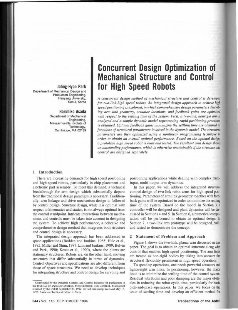
2 Sta tement of Problem and Approacb Figure I shows the two-link. planar ann discussed in this
paper. The goal is 10 obtain an optimal structure along with control that enables high speed positioning. The arm links are treated as non-rigid bodies by taking into account the structural flexibili ty prominent in high speed operations.
To speed up operations, one needs powerful actuators and lightweight ann links. In positioning, however, the major issue is 10 minimize the settling time of the control system. Residual vibrations and poor damping are the major obsta· cles in reducing the robol cycle time. panicularly for basic pick-aDd-place operations. In this paper, we focus on the issue of settling lime and develop an efficient method for
Transactions of the ASME
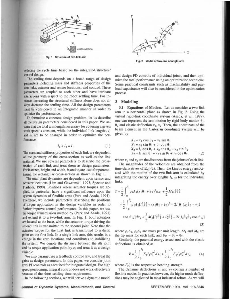
fig. 1 Stnlc:tu,. 01 two-llnk Inn
reducing the cycle time based on the integrated structure! control design.
The seuJing time depends on a broad range of design parameters including mass and stiffness properties of the arm links, actuator and sensor locations, and control . These parameters are coupled to each other and have intricate interactions with respect 10 the robot settling time. For instance. increasing the structural stiffness alone does not aJInys dccrcasc the settling time. All the design parameters must be considered in an "integrated manner in order to optimize the perfonnance.
To formulate a concrete design problem, let us describe all the design parameters considered in this paper. We as+ sume that the lotal arm length necessary for covering a given work space is constant, while the individual link lengths, I, and 12.0 are to be changed in order to optirnize the per+ (""""""".
11+11,= L ( ' )
The mass and stiffness properties of each link are dependent on the geometry of the cross-section as well as the link material. We use several parameters to describe the cross+ seclion of each link and treat them as design parameters. Forinstancc. height and width. hj and IVj are used for parametrizing the rectangular cross-section as shown in Fig. 1.
The total plant dynantics are dependent upon sensor and actuator locations (Lim and Gawronski. 1993. Speclor and Aashner. 1990). Positions where actuator torques are ap-plied. in panicular, have a significant influence upon the system dynamics of flexible arms (Park and Asada. 1991). Therefore. we include parameters describing the positions of torque application in the design variables in order 10 further improve control perfonnance. In this paper. we use the torque transmission method by (park. and Asada. 1991) and extend it to a two-link arm. In Fig. I. both actuators arc localed 31 the base. while the actuator torque driving the second link is transmitted to the second joint. Note that the 8Cluator torque for the first link is transntiued to a distal point on the first link. In a single link arm. this results in a change in the zero locations and contributes to stabilizing the system. We denote the distance between the ith joint and its torque application point by Cj and treat il as a design variable.
We also parametrize a feedback control law. and treat the gains as design parameters. In this paper. we consider joint level PO controls as a test bed for integrated design. For high speed positioning. integral control does not work effectively because of Lhe shon settling time requirement.
in the foll owing sections, we will derive a dynamic model
Journal of Dynamic Systems, Measurement, snd Control
y
~~-------------x
fig. 2 Model of two-llnk nonrlgld Inn
and design PO controls of individual joints, and then opti+ ntize the total perfonnance using an optimization technique. Some practical constraints such as machinability and pay+ load capacitance will aJso be considered in the optimization process.
3 Modeling
3.1 Equations of Motion. Let us consider a two-link arm in a horizontal plane as shown in Fig. 2. Using the vinual rigid-link coordinate system (Asada, et al.. 1989). one can represent the ann motion by rigid-body motion 6], 61, and elastic deflection "I . "2. Then, the coordinate of Lhe beam element in the Cartesian coordinate system will be given by
XI =XI cos 6 1 - VI sin 6 1 Y, =XI s in 61 + "~I cos 6. X2 = I. cos 61 +X2 cos 61, - "1, sin 62 Y2 = I, sin 61 + X1, sin 61, + "2 cos 61, (2)
where x. and X2 are the distances from the joinlS of each link. The magnitudes of the velocities are obtained from the
time--derivatives of Eq. (2). Then, the kinetic energy associated with the motion of the two-link arm is calculated by integrating the energy over lengths I], 12 for the individual links.
1 2'1, ~'2 .. cos 6121dx2 + 2" M1,(l16, + li6 2 + 211'26161, cos 6121
(3)
where p,A •• p2o'\z are mass per unit length. MI and Mz are the tip mass for each link. and 612 = 6, - 62,
Similarly. the pOlential energy associated with the elastic deflections is obtained as:
'f ll 2 If" , v= - E1/,vidx , +- EZ/2Vidx2
2 0 2 0
(4)
where Ej!; is the respective bending strength. The dynamic deflections v. and ' '2 COntain a number of
flexible modes. Ln practice. however. the higher mode deflec+ tions may be ncglected in most industrial robots. As we will
SEPTEMBER 1994. Vol. 116/345
verify through experiments later in Section 7. lhe deOeclion of each link can be modeled using a single mode as given by:
",(x,.t) = q,,(x,)q,(t) \' 2(X2, t) = q,2(X2)q2(t) (5)
Mode shapes 411. ~ are functions of mass and stiffness distribution. For a single-link ann, it is straightforward to calculate the modes. but in a multi-link case lhe exact mode is not defined because lhe system dynamics are non linear and configuration-dependent. The boundary conditions change as control is introduced to the beam dynamics. A feasible way to cope wilh the problem is to assume the mode itself. or to find modes by lhe finite e lement melhod assuming some boundary conditions.
The work done by the actuators can be expressed using the generalized coordinates defined above. Assume that lhe torques are applied al distances Cl. C2 from each joint. Particularly, when the second actuator is located on the ground and the torque is transmitted to lhe second link. the vinual work is given by
3.2 Ann Dynamics in Stopping Motion. The fundi· mental goal of this paper is to design an ultrahigh speed robot for point-to-point control. For rapid accelerations, II't first need high power actuators and a lightweight arm. Effi. cient control for improving speed of response and reducing tTaveling time mUSt be employed as well. However, the toW cycle time for point-to-point control includes a substantially large fraction of the time required for stopping. Residual vibration after arriving at a destination prevents the rt:lba: from quick positioning and prolongs the cycle time. There· fore. rapid stopping is as imponant as rapid acceleration to reduce lhe cycle time. In lhis paper. we focus on the stopping process and develop a technique for integrated structurtl control design.
In order to estimate how quicldy the residual vibrations will be damped out in the stopping processes, we will COIl·
sider lhe dynamics of the ann near the destination. To this end. Eq. (7) is Iinearized with respect to an operation painl at configuration (910. 920) in a rest condition.
Mx + Kx = Bu, (9)
(6) where lhe matrices and vectors are defined as follows:
Based on the single mode assumption. one can obtain the Lagrangian equations of mOlion.
1nJ]8 I + m 12th + (n la 2 + " 2th) cos 912
+ (n162 + " 2012)62 s in 9 12 = Tlln' 28 1+ muq) + k1ql
= 41 ;(ctlT,mlla 2 + InUq! + nla I cos 9 12 • 2 . ..
- (n 19 I + " 29)Q2) s in 9 12 = T 2111 229 2 + Innq2 . . + "291 cos 9 12 - n291912 sin 9u +k2q2
I', "I =1, P2A2X2dx2+M2/1/ 2 o
" "2 = II I P2A 2q,2(X2)dx2 o '1 ",2
kl = I £,/1411 (XI)dxl o
/12 .. 2
k2 = £2/ 2412 (X2)dx2 o
= 41 Z(C2)T2 (7)
(8)
The resultant equations are nonlinear, thus differing from the case of a single-link ann in which case the nonlinear terms are negligible if the elastic deOeclion is small. The nonlinear terms in the above equations accoun! for the Coriolis and centrifugal effects.
346/Vol. 116, SEPTEMBER 1994
In Il
m" o o
(
0 0 o k,
K = 0 0
o 0
o 0) o 0 o 0 o k,
U ={TI T2)T
n, CO~ e".,) m" mn
(10)
( 11)
(14)
If the angular sensor is collocated with the motor axis, !be output y = {9", .. 9",1}T is given by:
y=BTx. (IS)
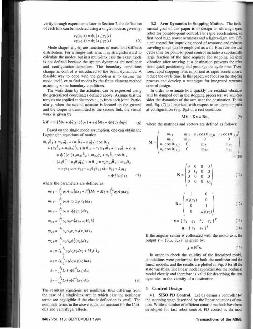
In order to check the validity of the linearized model simulations were performed for bolh the nonlinear and !be linear models. and the results are ploned in Fig. 3 for all the state variables. The linear model approximates the nonlincar model closely and therefore is valid for describing the ann dynamics in the vicinity of a destination.
4 Conlrol Design
4.1 SISO PO Control. Let us design a controller for the stopping stage described by the linear equations of!OOlion. While a number of efficient control methods have been developed for fast robot control. PO control is the most
Transactions 0' the ASME
• • ',m
• • vv 1 \j'v I • • •• ., ... .. , ... - -, .,(,,12) •
\jv -,
;I\r I- I •
• -, ... , ... - -~,
0 -_ ... .,1,/'2) ,. \jv ...
Av 0 , ! , ,
OM
"0 ... • • ... - -',m - • V .. ! o ., --.. , ---
" ... '. ... - -fundamental feedback Jaw guaranleeing stability as proven for rigid arms by (Arimolo and Miyazaki, 1983) and for nellble anns by (Lee. et al. . 1988), It is also involved in many advanced control schemes. In addition, various meth· ods developed for flexible ann control methods require fast sensors for monitoring elastic flexures 31 a high sampUng rate along with high-bandwidth actuators, which are infeasible 31 hlgh speed ranges. In this paper, we assume that only the position and velocity signals are available and we use PO control as I tesl bed for evaJualing the dynamic perfonnance of I flexible structure. In the following . a PO controller is desIgned in such a way that the seuling time in a slopping motion may be minimized.
FIl'SI. we design a nominal PO controller at a panicular ann configuration using the dynamic model. When the two links arc at a right angle to each other, the transfer functions for !he individual ffiO(or angles 9 ..
" 9 .. 2 are obtained from
Eq. (9).
, ,2 2 &. Im1l - 2mi'2~j(c;) + m/l~1 (CI))S + kj , _:0: 2 1 I , 1=1,2 T/ S l(mll m/l -m Sl )s +m l1 kd (16)
At this arm configuration, which is in the midd1e of the ... uk space, the arm dynamics are decoupled. We obtain the nominal controller that minimizes the settling time fo r this model. The obove transfer fu nctions can be simplified to
Jourtlll of Dynamic Syateml, Me.l urement, and Control
.,f-----....,q ., ., ·u o ·u . , • (., ~,
~ '---- ,. " ",--., • (-,
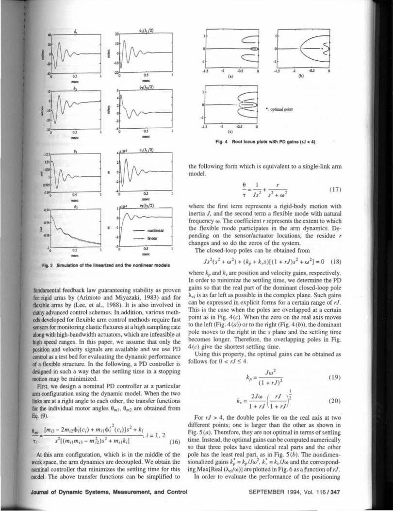
Fig. 4 Root locua pIola with PO plna (rJ < 4)
the following form which is equivalent to a single-link ann model.
9 , -:-+---T J s2 S2 +W2 ( 17)
where the fltSt term represents a rigid-body motion with inenia J, and the second term a flexible mode with natural frequency w. The coefficient r represents the extent to which the fl exible mode panicipates in the ann dynamics. Depending on the sensor/aClUator locations, the residue r changes and so do the zeros o f the system.
The closed-loop poles can be obtained from
JS2(S2+W 2)+ (kp + k • .s)I ( 1 +rJ)s2+w1J=D ( 18)
where kp and k"are position and velocity gains. respectively. [n order to minimize the settling time. we determine the PO gains so that the real part of the dominant closed-loop pole Ad is as far left as possible in the complex plane. Such gains can be expressed in explicit forms for a cenain range of rJ . This is the case when the poles are overlapped at a cenain point as in Fig. 4(c). When the zero on the real axis moves to the left (Fig. 4(a» or to the right (Fig. 4 (b», the dominant pole moves to the right in the s plane and the settling time becomes longer. Therefore, the overlapping poles in Fig. 4(c) give the shonest settling time.
Using this propeny, the optimal gains can be obtained as follows for 0 < rJ S 4.
lw' * • ,.,-=-=-;:-, p ( l+rJ )2 ,
k _ 2Jw (...!!....)' ~- I +rJ I +rJ
( 19)
(20)
For rJ > 4, the double poles lie on the real axis at two different points; one is larger than the other as shown in Fig. 5 (a). Therefore, they are not optimal in terms of seuling time. Instead. the optimal gains can be computed numerically so that three poles have identical real pans and the other pole has the least real pan, as in Fig. 5(b). The nondimensionalized gains k; '" kp IJw2, k: _ kvlJw and the correspond~ ing Maxi Real ("",,,w)1 are plotted in Fig. 6 as a function of rJ .
In order to evaluate the performance of the positioning
SEPTEMBER 1994, Vol. 116 / 347

• -E ·'L---=:;;;==l
.1 ...., 0 .. fig. 5 Root Iocul pIob wtth PO pint, (rJ >.)
f ,.
t ~ • -
•• ~')I
•
system. we use the conuol gains determined for a nomina] system as represemed by Eq. (16), which is equivalent to a single· link model given by Eq. ( 17). Then. the corresponding parameters of each link of the model can be obtained as follows:
m;)-mn
(2 1 )
By substituting the parameters imo Eqs. (19) and (20), the control gains *,1 and k .. can be obtained.
4.2 Efftd. of Plant Dynamics on Control System Per· ronna nce. According to Fig. 6, the beSt c1osed·loop poles are obtained when rl:: 4. Residue r of Eq. (17) represents the cxtenl 10 which the flexible mode panicipates in the plant dynamics. and rJ is the relative measure of the flexible motion to the rigid body mOlion. With this in mind. a physicaJ interpretation of Fig. 6 can be drawn. When rJ is large. i.e .• the nexibility is more prominent. the residual vibrations will be of long duration, resulting in a longer setlling time. If. on the other hand, rl is small. the effect of flexibility on the output will be small . However, a smaller rl makes the system less contrOllable (Hamdan and Nayfeh. 1989, Lindner et al., 1989).1 When r = 0, pole/zero cancellation occu~
'More «tmplt,e di lCuulonl on 'he a<:'U.'()I" loca,ionl of nuiblt m\l~lur'U .~ ."en ,n (Um and O ..... I1)II ... i . 1993).
3481 Vol. 116, SEPTEMBER 1994
'~L: :a \ &, ~ tU ~ ~ u ~ U U I
•
r~LSAd -0 0., IU tU ~ tu u o,J U o.t ,
• FIg. 7 rJ end control ~ _ • function of KtuItIon potnt dl
and contrOllability and/or observabili ty of the flex ible mode will be lost. In this case, the flexible motion of the ann cannot be contrOlled effectively, as Fig. 6 implies.
As shown in Fig. 4, not only the sySlem poles but also the system zeros which are dependent on rJ greatly affCCl the performance. In consequence, an optimum value of ,1 is equal 10 4 in the case of PO control. 1bert:fore. the InII
should be designed in a way that the elttent of flexible mode panicipation rl is close 10 the optimum value.
On the other hand, increasing the natural frequency Ii
directly related 10 performance improvement. 8y cbaft&u!l structural pantmete~, one can modify the plant dynamics so that the magnitudes of the poles may increase and the zero may be located al an optimal position. 1berc.fore, designing the s tructure and controller in an lnlegrated m&MC't
will yield an improved perfonnance of the contrOl system. The necessi ty for an integrated design lies at this point.
In panicular. the actuator location has a significant influence on the system dynamics and we wiIJ consider actuation point Cl as a design variable . Forexample. as Cl changes from zero to I, Maxi Real (Ad)] changes accordingly as shown in Fig. 7. The best perfonnance can be achieved when cllll :0:
0.23 or 0 .61. which is equivalent 10 ri l l = 4 . When cl"l::
0 .42. rl = 0 and Max(Real(A.edl = 0, i.e. the system is marginally stable. This is the case when the flexible mode is uncontrollable, and this point should be avoided for actUlll(K
location. In the previous subsection. the best PO gains were derived
for a given mechanical structure. and In this subsecOOa the best plant dynamics were obtained for a given cootrol structure. Combining the slrUcturaJ design with the coouol design will thereby yield an overall optimal pcrfonn:mceof the control system. In the following sections. optimizatioa will be perfomlCd to obtain the best structure and controller with various constraints imposed.
S MIMO Control and Performance Evaluation
In the previous section, single-inpul. single--output (SI50) PO gains were obtained for each individual link. They arc optimal for a particular ann configuration el l = ±90", where the two links are dynamically decoupled. For other configu. ra tions. the optimality might be los1. For a better perform-ance. a multi- input. multi-output (MIMO) control scheme
Transactions of the ASUE

"~"' . ..,.~ I'O"
.. '\ --.. ~ .. "::: •.. ~,
..... 01011110<10 ... 111 .. • "-"1 ..... 1
an be used to deal with the dynamic coupling between
"" links. To this end, we will consider the linearized equation of
motion given by Eq. (9). Assuming that the sensors and II:tUators are collocated and that only position and velocity Ire available, the sensor output and the actuator input are ;vm by
y:: BTx (22)
u=K,(y,,-y)+ K.(Y,, -Y}. (23)
where y" is the desired output and the MIMO control
gaUIs""
(24)
(25)
The closed-loop poles can be calculated by substituting the control law into the equations of motion. Eq. (9). Then, !he damping ratio and speed of response are obtained for the closed-loop. The detailed response depends on the configuration of the ann. since 8 12 is included in matrix M . However, the most important performance criterion would be the settling time which represents the speed of response. Itean be estimated approximately from the closed-loop poles and as a performance index we will adopl the real part of the dominant pole.
While the SISO PO gains for the individual joints can be found as a function of rJ as in Section 4.1, it is nOI possible 10 obtain the 0plimal gains analytically for the MIMO case. Inslead, the optimal gains can be computed numerically for each configuration. In Figure 8. the performance indices are plotted for the SISO PO gains and for the MIMO PO gains. The two curves coincide at 9t2 = 90°, since the SISO gains are optimal at the decoupled configuration and the two sets of gains are identical. At other 81l's, the MIMO gains show only small improvements over the SISO control. The SISO gains are constant regardless of configuration, but the MIMO gains are configuration-dependent. Moreover, there exist coupling gains kpiJ and krij. i '*- j . Therefore, MIMO control is of little advantage for this panicular case considering its complexity and that SISO control is simpler and close 10
Joumal 01 Dynamic Systems, Measurement, and Control
optimal.2 Later on in this paper, we wiU use the SISO PO gains for performance evaluation and actual implementation.
6 Design Optimization
6.1 Problem DefiniUon. Based on the perfomlance evaluation. the parameters of the plant dynamics are now modified in the direction of a beller performance. We will optimize the design with respect to the physical paramelers shown in Fig. I : length of each link 1;. tip mass Mj , height hi, width WI. and actuation point Cj.
The performance is measured by the real part of the dominant pole. which represenlS the speed of response. As shown in Fig. 8, however, the value is dependent OD the configuration as well as mass and stiffne.u properties. We then use a single index by laking the average of the performance measure over the joint position space D.
fD Max{Real(AcI)1 WdS
f· ID WdS (26)
where W is a weighting factor at each arm configuration. So far. we have formulated the performance evaluation with respect to joint motions. but actual positioning is performed at the endpoint in the lask space. In order to convert the joint-level performance to the one in the task space. we use the mobiJity measure associated with the inertia eUipsoid (Asada. 1983) for the weighting factor W. In the middle of the joint position space, the mobility is high, hence the weight W is high accordingly. whereas W is low at the peripheries or near singular points. The objective function f then represents the real part of the dominant eigenvalue which is averaged over the joint position space.
During optimization. a number of constraints were imposed on the design variables due to the limits of actuator size. work space, vertical deflection, and pay-load as well as manufaclurability. For example. the transmission mechanism of the second link to relocate the torque application point (park and Asada. 1991 ) may cause a manufacturing difficulty. In the following case study, we assume that the second motor torque is applied at the second joinl, i.e., C2 = O.
The actuator size limit imposes constraints on the arm link inertia. Coefficients 17111 and 1n2t involved in matrix M represent. respectively. the first and the second link inertia associated with rigid-body motion. It is desired especially for the gross motion that the inertia is as small as possible. We consider the inertia constraint given by
(27)
The total lengths of the links should be held conslant 10
maintain the same size of work space: It + 12 = L. In addition, the vertical deflections of the ann due 10 the gravity should remain small so as not to affect the overall positioning accuracy. The static vertical deflections were included as additional constraints. Since lhe vertical deflections are also configuration-dependent, two extreme positions were chosen to measure the deflections: I ) when the arm is fully stretched,
1MIMO coo!!oi In .eMnl may provide I beucr perfonnance in k""s of 0I1M:r """Irks such ••• n cloSC'd -loop pok's . cOIItrol effons. KDJi li"il),. la this piper. hoW<:v .... senli", time Is of primary imporUnCe od • foo;;ai ","aJ. As hla, as Kntia.lintc .. u cO<l'Iidcn'd u IlIe primary performan. MIMO cOIIIJOI prOvided vinultly no improvement ia OIIr Uperimenl ••
SEPTEMBER 1994. Vol. 116/349
i.e .• 812 = 0, 2) when the links are perpendicular. i.e., 812 = 90°. In the former case. the deflection &"1 is caused by bending only. In the latter case, the deflection B .. 1 comes from bending as well as from torsion . The fonnulations of the vertical deflections are listed in Appendix 1. and these are used as constraints in the optimization.
82 = B"I - B,-mu S 0
83=8"1-B"mu SO
(28)
(29)
Thus, the optimization problem is to minimize f while holding the equality and inequality constraints 8;'S. We employed the gradient projection method (Rosen, 1960-1961. Rao, 1978) which is based on the steepest descent method. In our optimization problem, however, the constraints are highly nonlinear. The original projection method is not directly applicable because the design variables may not stay within the constraint boundaries during the iterative computation. In addition, objective function f and constraints 8;'s are not always in explicit forms, hence it is difficult to find an optimal step size. We developed a revised method of nonlinear programming described in Appendix 1I in order to solve the problem.
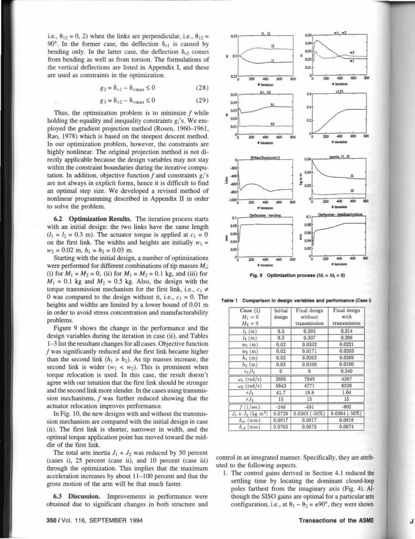
6.2 Optimization Results. The iteration process starts with an initial design: the twO links have the same length (1] = 12 = 0.3 m). The actuator torque is applied at Cl :::: 0 on the first link. The widths and heights are initially "'I = "'2 = 0.02 m. hi = h2 = 0.03 m.
Staning with the initial design, a number of optimizations were performed for different combinations of tip masses M,; (i) for Ml :::: M'l = 0, (ii) for M] ::: Mz = 0.1 kg, and (iii) for MI = 0.1 kg and Mz = 0.5 kg. Also, the design with the torque transmission mechanism for the first link, Le., Cl "F
o was compared to the design without it. i.e., Cl = O. The heights and widths are limited by a lower bound of 0.0 I m in order to avoid stress concentration and manufacturability problems.
Figure 9 shows the change in the performance and the design variables during the iteration in case (ii), and Tables 1-3 list the resultant changes for all cases. Objective function fwas significantly reduced and the first link became higher than the second link (h] > hi). As tip masses increase, the second link is wider (wl < wi). This is prominent when torque relocation is used. In this case, the result doesn't agree with our intuition that the first link should be stronger and the second link more slender. In the cases using transmission mechanisms, f was further reduced showing that the actuator relocation improves performance.
In Fig. 10, the new designs with and without the transmission mechanism are compared with the initial design in case (jj). The first link is shoner, narrower in width, and the optimal torque application point has moved toward the middle of the first link.
The total arm inenia 11 + lz was reduced by 50 percent (cases i), 25 percent (case ii), and 10 percent (case iii) through the optimization. This implies that the maximum acceleration increases by about 11-100 percent and that the gross motion of the arm will be that much faster.
6.3 Discussion. Improvements in perfomlance were obtained due to significant changes in both structure and
350 I Vol. 116, SEPTEMBER 1994
_a .• - ~
= ~
• '" G--~ u <.~-.-.. -.-.. -. om 0 0 ,. ...... _.-.. _.
~.
=, .. - a ~ " D - ~ ~ .- .-" .. ~ ..
,~ .. .. om
/ 0 .. I .. " ~. ~--.-
" D ~ .. ~ " D - ~ ~ ...... .-, '" ~ I~ t-
o ,~
" 0
~ • -- -.. - ['-- " .1000
0 D - a ~ " D ~ ~ ~ ...... . ..... " " ,. '" 1,-------
I'· '" I", '" .. .. " D .. a ~ " D ~ .. .. ...... .-
Flg.1 Opllmlullon proc ... (M, • M,. 0)
T.bIe 1 Comperlaon In dHlgn v.n.blee end petfomlolrlCe (C_ I)
i design
control in an integrated manner. Specifically, they are attributed to the following aspects.
I. The control gains derived in Section 4.1 reduced the settling time by locating the dominant closed·loop poles farthest from the imaginary lUis (Fig. 4). Al· though the SISO gains are optimal for a particular arm configuration, i.e., at 61 - 82 = ±90°. they were shown
Transactions of the ASME J

TItIIt 2 Comperl.on In H,lgn v,n,bl .. and Pfiform,nc. (C, .. lIj
i i design
i without with
transmission transmission
TIIiM 3 Compolln.otl In M,lgn nrlablto' and poIIrlormanc. (Ca,a Ill)
, ,
to be near-optimal for other configurations in tenns of settling time.
2. As a result of the optimization process, the plant dynamics of the ann link was modified. The open-loop poles and zeros are compared for the initial and final designs in Fig. 11. The magnitudes of the open-loop poles of the system, i.e., the natural frequencies. were increased while the zeros of the system moved in some way as a result of the computation. The pole/zero pattern was not optimal, however, as one can see that the final design's rJ's are not equal to 4 in Tables 1-3. This fact results from the constraints imposed on the optimization problem; without those constraints, the final design would be such that rJ = 4 to achieve the best perfonnance. Nonetheless. the final designs will have a much improved settling time as indicated by the closed-loop poles in Fig. 12. From the figure. one can see that the dominant closed-loop poles moved to the left in the s plane, while other less significant poles moved to the right. The optimization rearranged the closed-loop pole locations by oplimally redistributing the mass and stiffness of the arm.
Journal ot Dynamic Systems, Measurement, and Control
Ot====::Jla====::::J1 (a) Initial desiiC
01=====-1===111 (b) Fu!aI design (without traD$III.iuion)
Ot===::::lll====-I (c) FmaI design (with transmissiOll)
Fig. 10 Inltl,l ,nd tln,l de,lgna (C .. a 11)
," , ...... , .......... "-
" " 0 0
1 • 1 • .., .., ., ., .., • "
., ., .., • " """., ..... , , . I"""' t ....
" " j 0
• :1 • ., .., ., ., . , • "
., ., .., • " """., ..... " Fig. 11 Open·loop poIaa and zeroa for Initial and flna' M algna (Ca .. 11)
Closed·Loon Poles
:: .:
. .,.,L-=_-",,----! ·2000 .1000 0
Re:al(s)
+: initial design
. : final design
Flg.12 Cloaad-Ioop poII.lor Initial and Ilnal daalgn (C .. all)
SEPTEMBER 1994, Vol. 116/351

~
i 1[
" ' . ~ [, - i I I , ,
! I1 1I , t!
I , !
... , ..---..1 -{{ .... q
" -
...... • 11--..2 b.,
,It I •
At-,.. Two4Ink."" d .. IQ" (lop view)
3. While the control performance was optimized, the inenia of the arm links was reduced. The time allowed for the gross motion will be thereby shortened, reducing the tmal seuling Lime.
7 Prototyping and Experiments
Based on the optimal design obtained in Section 6, we now design and fabricate a high speed arm. The optimization results with respect to torque application points. link lengths, heights and widths as well as PO gains have provided critical guidelines for designing a prototype ann. In panicular. relocation of torque application points has been a significant conuibution to the performance improvement as seen in Section 6. We need to devise a transmission mechanism along with the whole ann structure so as to meet the design guidelines oblained above.
In this section. we deal with a particular ann design in order to verify the integrated design method proposed in the previous part of the paper. The model was augmented by incorporating dynamics of the transmission mechanism and the mechanical components involved in the real hardware. The optimization package was also revised to accommodate additional constraints.
7.1 Prototype Arm Design. The system consists of an arm linkage. direct-drive motors. tachometers. and a computer. The control loop is shown in Fig. 13. In order to drive the arm, two direct drive motors were used (Shin Meiw3 B 18-64). The velocity feedback was done in an analog circuit using tachometers (Inland TG-2936). The position was read from the encoders and sent to a computer for position control.
The structure of the protmype arm is shown in Fig. 14. The arm is composed of two links and two pairs of connect-
352 I Vol. 116, SEPTEMBER 1994
Model Simple model
Comprehen5ive model 84 Experiment 70
Frequency (Hz)
324 370 281 ~91 1680 210 460 750
ing rods used as transmission mechanisms. The lower pair of connecting rods connect the rotor of the lower motor 10
the torque application point on the first link. The upper pair of rods run from the upper motor rolOr to the second joint to drive the second link. A solenoid for picking up a wOO:· piece was attached to the endpoint.
7.2 Transmission Dynamics. The model in Section 3 was devised for an ideal system. i.e .• the actuator is assumed 10 have an infinite bandwidth. The assumption is not valid for the prototype design s ince we have a transmission mecha· nism which affects the dynamics of the whole system. The exact model would be too complex to be used for the inte· grated structure/control design. Since the optimization needs to be performed iteratively, it would take an enonnous caJcu· lation time to update the exact model many times during the optimization process. One way to cope with this problem is to develop a s imple. practical model.
The transmission mechanism itself is a continuous system including inenia and compliance. A cominuous model for both the beam and the transmission could hardly be obtained.. It is feasible to treat it as a lumped parameter system WIJII
spring-mass idealization. The equation of motion in Secuoa 3 is then augmented as follows.
mile 1+ ml2ql + (nle ! + n2q2) cos DI! + (11192
+ II 2q 2) 92 sin DLl + k'l lD I -+ $l(cl)ql - 6.d =0
ml 2el + ml3ql + klql + kll<Pl(c')f9 1
+ $I(CI)q1 - 8.11 = 0
Jm1am1 - k,dD I + $I(CI)q1 - 9m d ::"1
ml l e2 + mnih + 'l la l cos D12 - (11191
+ IIzl12)D I sin DI! + kalD! + $ 2(CZ)qZ - 8.-11 = 0
m22a2 + m2Jq2 + n2a, cos DI2 - 1119,912 sin 61 2
+ k2'/2 + k12$2(Cl)(6l + $2(c2)q2 - 8.11 = 0
J,.a6m2 - k12192 + $2(C2)q2 - Dml.l :: "2 (30)
where k".'s are spring constants of the transmission lines. Jml's are inertias of the rotors and the hubs, and 9.,·s represent angular positions of the rotors. As in Section 3. lincariza· tion of the goveming equations was made to describe !be stopping mOlion around a destination point (6100 620).
The validity of the augmented model was checked by experiments using the protOtype arm described earlier in this section. An accelerometer was used to measure responses when the arm was excited by random signals. Then, by using a Fast Fourier Transfom\ (FFr) analyzer. the fundamental frequency componentS for the links were obtained. The results are shown in Table 4. The experimental frequencies were lower than those derived from the model. Unmodelcd compliances existing in the mechanism contributed to 10110"
Transactions of the ASME

for ped. wim tion
=0
, 0
es, ,".
",.
be
by us es >g aI e·
,. E
T .... 5 ~ In .. Ign vaNble. and pertonnance
aing the natura] frequencies in the real syStem. Nonetheless. !be new augmented model improved the accuracy of the model significantly by reducing the error in the natural fre· qutncies. The lowest frequency was accurate within 20 perctnI. But the higher frequencies were nOI well predicted by !be model because assumed modes were used. The higher frequencies of hundreds of hertz may not be excited in practice and so their inaccuracy in the model might be neglilib •.
7.3 Modified Design. The complete model described III !be previous section was used for optimization of a real wm. However. the real system has additiona1 conslrai.nts resulting from the hardware as well as additional dynamic 1CmlS. In proceeding with the oplimizalions. these practical ISpects ,should be incorporated into the optimiuuion problem.and the design problem should be redefined accordingly by taking intO account those practical factors.
The same objective function represeming a weighted average of the dominant pole given by Eq. (26) was used to improve the settling time. Since the actuator size is fixed. the individual inertia should be reduced in order to achieve fISt positioning of the robot ann. Hence. the inertiaconst.ra1m should be imposed on both links. i.e ..
j -:: I. 2 (31 )
The computations in Section 6 resulted in unusually large feedback gains, which are practically infeasible because such high gains would amplify the sensor noise and degrade the perfonnance. The noise problem especially is more prominent in the velocity feedback loop. The maximum values of the gains were obtained empirically.
kpl'5. kpfl1u, j-:: I, 2 (32)
i", I. 2 (33)
The initial prototype was designed according to the dimensions as listed in Table 5. For the robot ann design, the inertia should be reduced for higher acceleration while impro\ing the closed-loop perfonnance. Thus, we imposed a tight inertia constraint in order to reduce the higher inenia 33-50 percent from the initial design. Then. 1 111W. '" 0.67 J,.. or 1; mu '" 0.51/ iIIiI. Table 5 shows the optimization results. Final design I included link lengths 1/ as design \'ariables, but fmal design IJ did not.
Since the inertia was reduced significantly, the ann links l1o'()Uld be more flexible hence improvement in perfonnance
u Joint 1 (', l
1 ~V , L-
~. G a a - - ---., Joinl '2{9,)
·u / 1 • i\ ~. ,. a - - m ---FIg.1S Te.t with the tnltlet <leelgn
~'~--'a"--~_"---'_'---'_'---'''''--.i"" --.ur-_;==c--~=;==J~ .. ~· ~·'~'~~==~------__, ."
1·',& r I 'I : y
.,.
" .. --, F~ 1e Teat with the tmproved dHlgn
fwas relatively smaU . But the total settling time for positioning the ann will be affected by both the inertia and the time constant f of the residual vibrations. Therefore, the new design is expected to improve the positioning perfonnance significanlly. The resultant changes in venical deflections were minimal. For comparison, the initial design and final design lJ were implemented to perfonn tcsts.
7.4 Test Results. To demonstrate the effectiveness of the new design, experiments were perfonned for both the initial design and the improved designs.
I. Figure 15 shows the joinl positions of the initially designed two- link ann. 11 was able to move between two poinls 25.4 cm apart up to twO round trips (four moves) per second. This includes a reasonable amount of time allowing for pick-and-place operations.
2. Using an improved design whose test results are shown in Fig. 16, the manipulation speed could reach three round trips (six moves) per second. This im· provement is in part due to the reduction in inertia and in part to closeness 10 the optimum.
3. Finally, the optimized ann was fabricated. Fig. 17(0) shows the two joint positions for the same tcst points as in Figs. 15 and 16. The manipulation speed was increased to four round trips (eight moves) per second. The settling time is less than 10 ms. The closed-up view of the second joinl response is also shown in
Journal of Dynamic Sys tems, Measureme nt, a nd Control SEPTEMBER 1994. Vol. 116/353

O.7.5rad
(
, \
-o.~ .ad ,OO \
\ I ~+~J 1\
-..(1 \ If I !
'iD 0.20 o.ll TUE h)
1, ;; ~ ,
, , I. U , . .. nil (. )
Cb) ~ Link ra~ Dcv lhe 6.nal pomtioD
flsj. 17 Tnt with the final de.lgn
's
Fig. l7(b) with the full scale of 2 mm. which shows that Ihe steady·state error was less than 0.4 mm. To sec Ihe endpoim response. the endpoim motion of the second link was measured wilh a laser proximity sen· sor. and is ploued in Fig. 17(b). In summary, the speed of poinHo-point motion was increased to twice that of the initial design.
The optimization carried out in the above has two aspects for improving the performance. One is to increase the maximum acceleration during the gross motion by limiting the inenia within a smaller value. The other is to reduce the settling time by minimizing the time during which vibration is danlped out. These two improvemems contribUled 10 reducing the total cyclic time of the poim-Io-poim motion of the arm.
8 Conclusion
An imegrated design method for robol arm structure and controller has been presemed. Comprehensive design parameters consisting of arm link geometry, actuator localions and feedback gains are oplimized with respect to the settling time of the system. First. a two-link. non-rigid arm model was obtained and then !inearized to describe rapid positioning processes. An optimal PO controller was designed for the non·rigid arm model minimizing the sellling time for a nominal configuration. It was shown to be close 10 optimal for other configurations in terms of settling time. In order to evaluate the configuration-dependent performance. a
354/ Vol. 116, SEPTEMBER 1994
weighting faclor was introduced taking !he i arm imo consideration. The structural parameters were oplimized in order to obtain an improved performance.
To demonstrate the integrated design . ann design was implemented and a case for redesign of this arm. The resuhant ann design outstanding performance. which is o!IlecW;'~ IlIUrutilUboi one considers struc!ure design independenl of control.
An imegraled design method requires a p"~,fi"od,_ law and a performance criteria. depending on which design will be different. In this paper. the settling used for perfonnance evaluation and optimization ing PO control. For future work. one can consider perfonnance measures andlor advanced controllers MIMO control schemes and nonlinear control. ~~~: ing more practical constTaints. such as stress di will help improve the ultimate perfonnance and the new design.
References
MedwusmJ. ~ Prw.
mini: Pan 11. • Sp«~OI" V. A. and FllShna. H .. 1991. •
of NoncoUoc:atcd Control in Flu ible Sys~eltUi." SVST£MS. MEASUUMENT. "' .. 'OCOImtOt.. Vol . 1
TirrIo$ehnko. S. and Cioodier. J. N .. 1910. McGra .. ·· HiIl. New York.
APPENDIX I
Vertical Deflections I. Deflection due to bending when 612 = 0
,. BC
'" ID
if
.1 aI .. s".
" J-s. 'f
• • •
,
+ 2M2+2PA!/l /2]
" g/~ [PA2r]. M2] 01>2"'- -+-
E2/,,! 8 3
11. Deflection due 10 bending/lOrsion when 912 = 90"
5_2 = Ii,l + 5,2 + iz<p,
g I~ [PA 111 .M.::!.., +:.::M:!,,,+:,:P,,,A",,,,,,I,] 5,1=- --+-
EI / , 1 8 3
5,2. 8/~ [PAll]. + M2] E2 / ,/2 8 3
(pA l l zn + M 2)8 / ,/2 q,,=c(a,b) J
Glob
.. b coefficient c(a. b) is given by; (see Timoshenko and Goodi<r. 1970)
I n'Tfb) -Ianh-nS 2a
APPENDIX 11
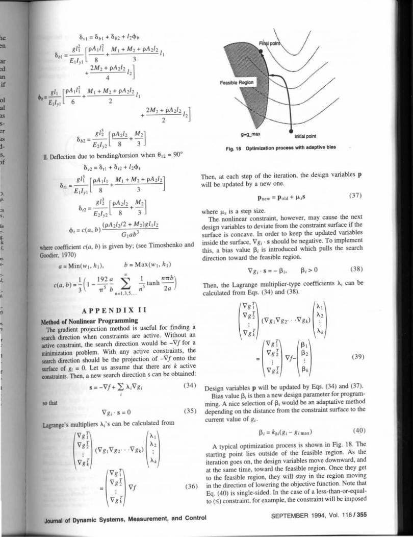
Mttbod or Nonlinear Programming The gradient projection method is useful for fmding a
search direction when constraints are active. Without an active constraint. the search direction would be -VI for a minimiz.ation problem. With nny active consu-ainls, the search direction should be the projection of -Vi onlO the surface of gf = O. Let us assume that there are k active conslnlinlS. Then, a new search direction s can be obtained:
(34)
.. Iba, (35)
(36)
g-Q...max .... -Flg. l1 Optimization proc ... wl1tl act.ptI .... bias
Then. at each step of the iteration. the design variables p will be updated by a new one.
p~c ... '" P old + v..s (37)
where v.. is a step size. The nonlinear constraint. however, may cause the next
design variables to deviate from the constraint swface if the surface is concave. In order to keep the updated variables inside the surface. V 8/ . s should be negative. To implement this. a bias value 11, is introduced which pulls the search direction toward the feasible region.
(38)
Then. the Lagrange multiplier-type coefficients Ai can be calculated from Eqs. (34) and (38).
(39)
Design variables p will be updated by Eqs. (34) and (37). Bias vaJue III is then a new design parameter for program
ming. A nice selection of 11, would be an adaptative method depending on the distance from the constraint swface to the
current vaJue of 81·
(40)
A typical optimization process is shown in Fig. 18. The starting point lies outside of the feasible region. As the iteration goes on. the design variables move downward, and at the same time. toward the feasible region. Once they get to the feasible region. they will stay in the region moving in the direct ion of lowering the objective function. Note that Eq. (40) is single-sided . In the case of a less-than-or-equalto (~) constraint. for example. the constraint will be imposed
JoumII ot Dynamic Systems, Measurement. and Control SEPTEMBER 1994, Vol. 116/355

when the current value 81 exceeds the limit value 81 mu' Otherwise, 8, is not included for consideration and ~, = O.
The higher the gain k~ is, the more closely the equality condition will be met.
For equality constraints, the adaptation for bias 131 is twosided and the following adaptation law will guarantee that the constraints remai n close to the fixed value.
Using the nonlinear programming tecbn.ique, the optimization can be carried out with linear or nonLinear constraints. Another feature is that the initial guess does not necessarily have to be within the feasible region as with other gradientbased mathematical programmings. (4 1 )
•
27th CIRP International Seminar on ~ Manufacturing Systems
'1 I May 21-23.1 995, Ann Arbor. Michigan DESIGN. CONTROL AND ANALYSIS OF MANUFACTURING SYSTEMS
.-.
"""" "'" T.m. UrMrsiW Bertn. Germany
TOSHIOSATA !ben InsIiII.U Tokyo. JIpIn --I.kWtrIiIy 01 ~ Skwlnia
BERTI. COOl"" CoI*og ~t. Cull .. US.A
...... --Y. ALTMAS ThI ~ 01 B. C .. t.I8dI
MA ElBESTAWI MleMwer lIniYmiIy. Cana.cs.
Y. KOREN.s.-~ TIlt ~0I~. U.SA
AtoIN< ~ UrtrvmiIy. s-iItn
.PRITSCHOW lWttrsdI SII.cIr;an. GemIIny
M.SHPITALHI T.anIon.lIt_
' .SUH ~hI. oITtdI.. U.S.A
~ TOIIZOO I.kMIsify 01 c.torria. U.5.A.
H. VAN BRUSSEl ~~~. 8eIgUn
I,G.IJ.....<'O':' TIll UriYersity 0I~. U.SA
~ """ TeoIwt Hoc:hIctUe~.
It. YOSHKAWA Ikwt!tify 01 Tokyo, JII*' --O. BI..ASCA • a-r.: Ibn E. KNfi.I.TEY-ASI8U. LN Y. I<OREH • LN. Chair J.N·LU J.$T9I·LU C.L 'MJ. Ford Motor Compiny H. IW.O..~ AIIlItn
CALL FOR PAPERS
THEME: DESIGN, CONTROL AND ANALYSIS OF MANUFACTURING SYSTEMS
The University or Michigan, Ann Arbor. Michigan.
Please send to the Program CommiUee, at the address below, a t-page length abstract on one of the rollowing topics:
• Work cells and workstatlons - planning and control • Monitoring, diagnostics and precision Machining • Modeling. simulation and Idenllficatlon • Concurrent engineering • Multiple-resources planning, logistics • AdapUve and Intelligent control • Intelligent systems and machines • Design and control of robots • Control a rchitecture and InfonnaUon bases • Equipment design • Other topics rtlated to the Seminar Theme.
The deadline for submitting the abstracLs is October t, 1994.
Authors of Abstracts that are favorably reviewed will be asked to submit a complete manuscript by December IS, 1994.
Ann Arbor i$ localed IIppn:u:imalely 30 minutes from Detroit Mclm Airport
The 1995 NAMRC is in Hooghton. Micrugan May 24-26.1995.
!'rOlum In M.nllfaclllrh.&!C IRP p ......... Com .. tllH 21 " GG 8.0""
pbo&o, ()U) '''''''71 (lU) 7"")3U
r .. : (lll ) '~7 ·00'!I 1'1110 Unht ... lI)' ot MI~b ll'"
1350 H., ,,ard SI,,"1 Ann Arbor. MI ~U09·11 2!, USA
3561 Vo!. 116. SEPTEMBER 1994
£· .... 11, Vo . . .... Korn ltum.u.umlcb.tclu £·m.lI , btk. t .. &I • . uml~b.tclo (Htld . K.mllj
Transactions ot the ASIIE