concurrent engineering - koç hastanesihome.ku.edu.tr/~ibasdogan/papers/a1.pdf · concurrent...
TRANSCRIPT

http://cer.sagepub.com
Concurrent Engineering
DOI: 10.1177/1063293X09102252 2009; 17; 73 Concurrent Engineering
Ipek Basdogan Collaborative Design and Modeling of Complex Opto-mechanical Systems
http://cer.sagepub.com/cgi/content/abstract/17/1/73 The online version of this article can be found at:
Published by:
http://www.sagepublications.com
can be found at:Concurrent Engineering Additional services and information for
http://cer.sagepub.com/cgi/alerts Email Alerts:
http://cer.sagepub.com/subscriptions Subscriptions:
http://www.sagepub.com/journalsReprints.navReprints:
http://www.sagepub.co.uk/journalsPermissions.navPermissions:
http://cer.sagepub.com/cgi/content/refs/17/1/73 Citations
at Koc University on November 3, 2009 http://cer.sagepub.comDownloaded from

CONCURRENT ENGINEERING: Research and Applications
Collaborative Design and Modeling of ComplexOpto-mechanical Systems
Ipek Basdogan*
Assistant Professor, Koc University, College of Engineering, Department of Mechanical Engineering
Rumeli Feneri Yolu, 34450 Sariyer, Istanbul, Turkey
Abstract: In this article, we propose a concurrent design methodology that employs physics-based high fidelity computational models together
with analysis methods to predict the performance of complex opto-mechanical systems. For this purpose, we developed a web-based
collaborative design and modeling environment for the simulation of complex opto-mechanical systems (SIMCOMS). The analysis tools and the
methodology presented in this article provide a systematic and quantitative way to investigate the end-to-end system performance of such
systems, perform sensitivity analysis, and identify the critical components of the system that degrade the performance. The SIMCOMS
integrates all the modeling and analysis tools in a common MATLAB computational environment and it can be accessed through standard web
browsers. Through the use of structural, optical, and controls modules, SIMCOMS allows modeling and SIMCOMS. The analysis modules of
SIMCOMS provide the means for predicting the performance of such systems and diagnosing the problematic components that degrade the
performance. The web interface of SIMCOMS provides a flexible and robust environment for designing such complex opto-mechanical systems
and keeps an archive of models to compare different design configurations. The design can be conducted concurrently by multidisciplinary
teams located physically at different sites, which leads to savings in time and cost. We demonstrated the use of SIMCOMS through a case
study which includes the redesign process of a siderostat mirror; one of the main optical components of the SIM PlanetQuest (formerly called
Space Interferometry Mission). SIM will determine the positions and distances of stars several hundred times more accurately than any
previous program. SIM provides a good example case for testing the functionality of SIMCOMS since the precise tolerance required by the SIM
instrument facilitates the investigation of many design options, trades, and methods for minimizing interaction between the actively controlled
optics and the structure.
Key Words: integrated modeling, collaborative design, opto-mechanical systems, performance prediction, multidisciplinary teams.
1. Introduction
Designing complex opto-mechanical systems is ahighly challenging activity that involves multi-disciplin-ary teams work together to achieve the optimal design.In this study, we developed a web-based modeling andsimulation environment (SIMCOMS), which allows acollaborative design environment for multidisciplinaryteams. The teams, each working simultaneously atdistant locations and on different platforms, canaccess the SIMCOMS using standard web browsers.In the proposed approach, multidisciplinary design ofcomplex opto-mechanical systems can be conductedconcurrently.
During the design phase of a project, addressing themajor technological challenges at the system-level couldbe very difficult, time consuming, and costly due to thecomplexity of the design problem. In those cases,computer-based models and simulations become anintegral part of the development process to test and
verify the system level performance. System-level simu-lations, performance verification, design changes couldbe easily performed using the computer-based modelsuntil the design becomes mature. All these processesget even more complicated when designing complexmultidisciplinary systems since these systems are com-posed of subsystems from different fields. Space systemsare good examples of such multidisciplinary systemssince they combine structures, optics, and controls inorder to meet their stringent requirements.
There are already a few modeling and design toolsavailable for the integrated design of complexspace systems, which include TRW’s IntegratedConcept Design Facility (ICDF) [1], Jet PropulsionLaboratory’s (JPL) Project Design Center [2], Boeing’sConcurrent Integrated Engineering Laboratory (CIEL)[3], Aerospace Corporations’s ‘Concept Design Center’(CDC) [4], and European Space Agency’s ‘ConcurrentDesign Facility’ (CDF) [5]. The models used in thesefacilities are not heavily based on physics and mathe-matics. They are mostly used for ‘back in the envelope’calculations, which can give quick and rough estimatesof the system performance during the conceptual designphase. Considering the need for higher fidelity models,the Aerospace Systems Design Laboratory (ASDL) at
*E-mail: [email protected] 1–11 appear in color online: http://cer.sagepub.com
Volume 17 Number 1 March 2009 731063-293X/09/01 0073–15 $10.00/0 DOI: 10.1177/1063293X09102252
� SAGE Publications 2009
Los Angeles, London, New Delhi and Singapore
at Koc University on November 3, 2009 http://cer.sagepub.comDownloaded from
Georgia Tech has launched their own facility‘The Collaborative Design Environment (CoDE)’ [6].The CoDE will enable researchers to develop, test, andapply new approaches to conceptual design by utilizinghigh-fidelity modeling, simulation, and analysis tools ina collaborative team-centered environment.There are also various collaborative design and
manufacturing tools that has been developed for variousengineering systems. Chang et al. [7] has developed aweb-based collaborative system for integrated designand manufacturing of mechanical parts using JAVAand VRML. They focused on the framework ofthe collaborative system and discussed how it wasimplemented in the design and collaboration modules.Another concurrent design and manufacturing toolhas been developed by Chang et al. to employ physics-based computational methods together with computergraphics techniques for product design of mechanicalsystems [8]. Their modeling and simulation tools weretested on an airplane engine to simulate productperformance, reliability, and manufacturing cost.Distributed object-based environment (DOME) isanother modeling tool that is developed by MITCAD-Lab that concentrates on integrating varioustools that can be used for product development [9].It provides the links between the design, manufacturing,and marketing departments. Different from the otherdesign tools, DOME allows detailed analysis optionsbut its main focus is to develop the architecture thatfacilitates the integration of the commonly usedcommercial products. Kalsi et al. [10] introduced atechnique to reduce the effects of uncertaintyor variation in design parameters and incorporateflexibility into the design of complex systems involvingmulti-disciplinary teams. They use the concepts ofrobust design to reduce the effects of decisions madeduring the design of one subsystem on the performanceof the rest. Another technique developed by Chen andLewis [11] integrates game theoretic models of the designprocess with robust design techniques in order to reducethe effect of the coupling between the subsystemsand improve the performance of the overall system.A computer program, developed by Ollinger andStahovich [12], uses model-based reasoning to generateand evaluate proposals of redesign plans for engineereddevices. These proposals describe how the designparameters could be changed to achieve a specifiedperformance goal.The lack of high fidelity tools for design of complex
space structures spurred the growth of two MATLAB-based software packages at JPL: a structural packagecalled integrated modeling of optical systems (IMOS)and an optics package called modeling and analysisfor controlled optical systems (MACOS) [13,14]. Overthe years more and more applications and capabilitiesare added to these packages and they have evolved into
a sophisticated modeling environment to conductend-to-end performance analysis for complex opto-mechanical systems. The modeling methodology hasbeen validated at JPL by comparing model predictionswith the test-bed measurements [15,16].
In this study, we expanded the capabilities of theIMOS and MACOS by developing new analysis toolsfirst and then integrating all these tools into a web-basedmodeling and simulation environment. SIMCOMS canbe used to conduct concurrent engineering throughvirtual testing of complex opto-mechanical systems.The result is a multi-disciplinary tool that enables a userto integrate models from different disciplines andconduct performance analysis that would otherwisebe exceedingly difficult with the real hardware. Thesimulation environment is a collection of functionsthat operates in the MATLAB environment. TheSIMCOMS integrates structural, optical, disturbance,and control system modeling into a common MATLABcomputational environment and provides variousanalysis options to construct ‘‘what-if scenarios’’ forattacking various design questions through simulations,thus minimizing hardware tests. The SIMCOMS alsoincorporates several graphics functions that enablevisualization of structural assembly, structural deforma-tions, and elementary optical layouts. The SIMCOMScan be further expanded by the user by writing his/herown MATLAB functions. The simulation and visualiza-tion tools allow the identification of the criticalcomponents that degrade the performance of thesystem and also the evaluation of the design tradeoffsvery efficiently.
SIMCOMS is accessed via a web-browser through a‘point and click’ graphical user interface (Figure 1).Working within the design environment, the analystsand design engineers can easily exercise the main systemand the components under various conditions, perform-ing the same tests they would normally run in the testlaboratories that would take months or years. Targetusers of such a modeling and simulation tool includedesign engineers, system engineers, analysts, and at somelevel, project managers. SIMCOMS is intended for useduring the design phase of a project, when engineersneed to make quick, yet accurate assessment ofthe overall effects of a particular design change. Theframework combines a collection of user interfaceprograms and external MATLAB routines. The userinputs provided through a web-interface invokeMATLAB code or externally defined functions.While understanding the basic theory employed in theprograms is required, the users may not be intimatelyfamiliar with the program’s input syntax and all thedetails of the MATLAB functions. Users can animatecomponent or system dynamics on-screen, displaygraphs or important parameters, save and printtheir analysis results directly from their local computer.
74 I. BASDOGAN
at Koc University on November 3, 2009 http://cer.sagepub.comDownloaded from

They can progressively refine and retest their designsuntil the required performance is achieved. The web-interface can include a library of models of the currentproject and components that can be also used as anarchive to make comparisons between recent andprevious design configurations. The web-based environ-ment also provides means for communicating theinformation among different disciplines, groups, andorganizations, which is especially crucial in large-scalecollaborative projects. The platform independent frame-work makes all kinds of knowledge available to anyone,located anywhere, at any time.
To demonstrate the use of SIMCOMS, we selected acase study, which involved the redesign process of asiderostat mirror, which is one of the main opticalcomponents of the SIM PlanetQuest (formerly calledSpace Interferometry Mission). The interferometercollects the starlight from two physically separatedcollectors and via a series of mirrors, brings thelight to a beam combiner where they are interfered.It is comprised of a complex optical train composed ofnumerous collecting and actively steered optics. Theoptical elements are mounted on a lightweight trussstructure subject to dynamic, quasi-static, and staticdisturbances produced during the course of on boardoperations.
Fundamental interferometer operation requiresthat the two independent telescopes view the same star[17–19]. The pointing control system is responsible forproviding this function (Figure 2). This system adjustsfour degrees of freedom: wave front tip and tilt (WFT)of the two incoming beams by articulating the siderostatmirrors with feedback from angle tracking cameras.
In this study, we investigated the effect of differentialWFT jitter resulting from the reaction wheel assembly(RWA) disturbances, which is the largest anticipateddisturbance source on the SIM spacecraft. The modelpredictions of the baseline design showed that the WFTperformance of the SIM instrument was above therequirement specified by the SIM science team [19].Utilizing the analysis tools of the SIMCOMS, we wereable to identify that one of the mode shapes of thesiderostat mirror mount coupled with the overall systemdynamics and degraded the WFT performance. Then wewent through a redesign process and stiffened thesiderostat mirror mount, which eventually improvedthe performance of the SIM instrument significantly.Considering the multidisciplinary components of theSIM: the optical instrument, the structure, and the waythe opto-mechanical system couples with the RWAdisturbances, it would not be possible to identify theproblematic components in such a complex system if wedid not use the integrated modeling methodology andthe analysis tools of SIMCOMS. The systematic and thequantitative approach presented in this article make itpossible to pinpoint the critical design parameters in thedesign space.
The case study presented in this article, the redesignscenario of the siderostat mirror mount includes thefollowing steps (Figure 3): first we develop theintegrated model of the baseline system. The integrationprocess involves the multidisciplinary teams create theirown models. This is where the structural, optical, andcontrol models are built according to the current systemspecifications. The structural model is first integratedwith the optics model to construct the state-space model
Optics designerStructural designer
Control designer
Figure 1. IMCOMS design tool used by multidisciplinary teams working simultaneously at distant locations.
Complex Opto-Mechanical Systems 75
at Koc University on November 3, 2009 http://cer.sagepub.comDownloaded from

of the integrated opto-mechanical model (see Section 3).The next step is to predict the WFT performance of theSIM instrument when the pointing control system isactive and the spacecraft is subjected to the anticipateddisturbance sources. This process is called the‘disturbance analysis’ and the transfer functions ofthe integrated model are used as the input for thisstep. The empirical reaction wheel disturbance modelsof the previous missions are used in this case study.
A MATLAB code, which propagates RWA distur-bances through the integrated model, is developedand integrated into SIMCOMS to perform the distur-bance analysis. The root-mean-square (RMS) values ofthe optical performance metric of the WFT arecalculated as a function of wheel speed. If the require-ments are met, the design is considered as candidate forfurther analysis and testing. If the performance is notmet, the sources of the unwanted dynamics are identified
Disturbance model(reaction wheel disturbances)
Further analysisand testing
Control model
Meet therequirement?
• Modal gain analysis
• Critical frequency analysis
• Strain energy analysis
• Sensitivity analysis
• Visualization of critical modes
Yes
No
Model integration
Opto-mechanicalfull model
(state-space form)
Reduced model(state-space form)
Optical, structural,control & disturbance
componentsmodel library
Analysis & visualization tools
Identifythe critical components
&component/subsystem
redesign
Open & closed loop opticalpointing performance
Figure 3. End-to-end performance analysis and a typical redesign scenario using SIMCOMS.
Optical performance
Disturbances
Complex opto-mechanical system
Control
(Pointing control system)
(RWA)
Pointing requirement ~ 0.03 arcsecond
Tip and tilt angle of the siderostat mirror
Figure 2. Schematic of the SIM pointing control system to adjust four degrees of freedom, tip and tilt of the two incoming beams to performinterferometry.
76 I. BASDOGAN
at Koc University on November 3, 2009 http://cer.sagepub.comDownloaded from

using the analysis tools and the design is revisited at thecomponent level until the overall system performancesatisfies the desired requirements. Before proceedingwith further analysis tools, the full size model is reducedto decrease the computational costs without losing theaccuracy of the model. The disturbance analysis isrepeated with the reduced model to verify that thereduction algorithm did not eliminate the modes that aresignificant to the system dynamics. All the analysis toolsdeveloped during the course of this study complementeach other to first identify the problematic areas andcomponents for redesign and then to improve theoverall system performance. The ‘modal gain analysis’calculates the modal participation factors from theRWA disturbance input to WFT as a function offrequency and uses the entries of the state-space modelmatrices as the inputs. The ‘critical frequency analysis’tool enables us to identify the critical modes of thestructure (i.e., the dynamics that appear to be the majorcontributors to the RMS metric) by convolving thetransfer functions of the opto-mechanical model withthe broadband power spectral densities (PSDs) of thecorresponding force or torque. The transfer functions ofthe integrated model and PSD of the RWA disturbancesare the inputs for this analysis. The ‘strain energy
analysis’ tool allows us to identify the critical compo-nents that have the highest strain energy. Strain energyof each component is calculated at the component levelwhere the structural model is developed. The ‘visualiza-tion’ tools in SIMCOMS are used to animate the criticalmodes and components to identify the problematicsubcomponents and verify the results of the earlieranalyses. The ‘sensitivity analysis’ tool enhancesthe understanding of the system by exploiting thesensitivities of physical parameters and performanceinformation around the local neighborhood of aparticular design. The details of these analysis toolsare given in Sections 5–10.
2. Architecture of SIMCOMS
The SIMCOMS makes use of Tcl/Tk and Tclextensions [20]. Tcl is a powerful and flexible scriptinglanguage, and Tk is a graphical user interface (GUI)toolkit working with Tcl. The SIMCOMS works bytaking advantage of Expect [21], a Tcl extension, whichsets up pseudo-terminals to interact with MATLAB.Figure 4 shows a brief description of how theclient/server Web application works. The Expect server
CGI
.
.
.
CGI
Spawns matlab
Spawns matlab
Spawns matlab
Spawns CGI
Spawns CGI
WebBrowser client
(1) Initial browser window
.
.
.
httpserver
.
.
.
Request/response via tty Write out m
ovie files
nfs
Rea
d in
mov
ie fi
les
Contents of movie via pipe
Interactivematlab
processes
Contents of movie via pipe
(2) Browser window with analysis results
Contents ofthe results
Matlabserver
(expect)
Simulation of ComplexOpto-Mechanical Systems
(SIMCOMS) TCP/IP socket
connection Request/response via tty
Request/response via tty
Figure 4. The client/server information flow for the SIMCOMS environment.
Complex Opto-Mechanical Systems 77
at Koc University on November 3, 2009 http://cer.sagepub.comDownloaded from

first spawns out MATLAB, and then listens on a TCP/IP socket port, waiting for Web Browser client connec-tions. TCP is a connection orientated internet protocolfor inter-process communication. A socket port,together with its host, forms the address of the providingservice, in our case, our Expect MATLAB server tool.When a client connects and sends commands to theExpect, the server routes the command to the spawnedMATLAB process, which then executes the commandand returns the result back to the Expect server viapseudo-terminals. The Expect server then sends theresult back to the client via TCP/IP socket connection.The result can be either text outputs from the MATLABprocess or images generated from MATLAB plottingroutines. However, in some client commands, the resultsfrom MATLAB are movie animations and, in thesecases, the movies are pushed back to the client via the‘Content-Type: multipart/x-mixed-replace’ technologythat allows the transfer of the movie clips through theCommon Gateway Interface (CGI) program. CGI isthe part of the Web server that can communicate withother programs running on the server [22]. After all theGIF images are created by MATLAB, Expect sends asignal to the web browser client to tell it to open a newbrowser window that points to the web link containingthe CGI. The CGI program tells the browser to mark acertain area of the web page and give it an internalname. After the page is initially displayed, the CGI cansend updated information to that page. In this case, theCGI program sends several GIF files, each one isdisplayed immediately by the browser before the nextone is received, and when the next one is received,it overwrites the previous one. This is a faster way toview the animations since we can see each frame rightaway as it is received rather than downloading all theframes before we can start to view it.To install the client side of SIMCOMS, the user has to
obtain and install Tcl/Tk web browser plug-in [23].Once the Tcl plug-in is installed, the user can view theTcl applet at a specified web address, which is theuser front-end for the SIMCOMS. The Tcl appletconsists of a few pull-down menus and sub-windows.The pull-down menus allow the user to bring upother popup GUI interfaces to perform differentanalyses. The results of the analyses are displayed onthe lower left ‘MATLAB console’ window. In someanalysis, resulting 2D/3D plots also return in separatewindows, which the user then can zoom-in, pan, orchange viewing angles. The user can also drag-n-drop these plots into the ‘blue canvas’ in the Tclapplet and resize, annotate, save, reload, and printthem. The SIMCOMS can be easily linked to otherapplications such as Microsoft Excel. The returnedresults can be in the form of Excel spreadsheets, and inthese cases, the Tcl applet can launch Excel to view theresults.
3. Integrated Modeling Approach
The integrated modeling methodology combinesstructural, optical, disturbance, and control systemmodeling into a common computational environmentand enables end-to-end performance evaluation ofthe SIM instrument before the system is built.The integrated model of the SIM instrument consistsof a structural finite element model and a linear opticalmodel. The structural model is developed using IMOS,whereas both IMOS and MACOS are used to create theoptical model. The user can select the required structuralmodels and assemble them using the SIMCOMSsub-menus.
To demonstrate the use of SIMCOMS, we selected acase study, which involved the redesign process of one ofthe main optical components of the SIM instrument.Although one case study has been presented in thisarticle to demonstrate the capabilities of the SIMCOMS,previously various studies has been done [15,16,24,25]that utilizes the tools of the SIMCOMS to predict andimprove the optical performance of opto-mechanicalsystems.
The following section describes the details of thestructural and optical models and how they areintegrated. Later, we describe a redesign scenariowhere we utilize the different modules of SIMCOMSto identify the problematic components and go throughthe redesign process, which eventually improved theperformance of the instrument significantly.
3.1 Structural Model of SIM
The finite element model of SIM structure has 27,000degrees of freedom (dof) and it is constructed usingIMOS functions within the SIMCOMS structuralmodule. This geometry consists of plate, beam, andrigid body elements, modeling the spacecraft and theinstruments. Sub-structuring and component modesynthesis techniques are used to reduce the size of thefinite element model to 1200 modes. The governingequation of the original system generated by the finiteelement analysis is
M€dþ C_dþ Kd ¼ Fu ð1Þ
where, M, K and C are the mass, stiffness, and dampingmatrices, respectively. The vector d is the nodaldisplacements, u is the control input, and F is theinfluence matrix for u. Then the system in Equation (1)is transformed to the modal coordinates as
MP €gþ CP _gþ KPg ¼ FPu ð2Þ
where MP, CP, and KP are diagonal modal mass,damping, and stiffness matrices, respectively and g is the
78 I. BASDOGAN
at Koc University on November 3, 2009 http://cer.sagepub.comDownloaded from

vector of modal coordinates [26]. Once these matricesare calculated, they are integrated with the matricesobtained from the optical model to form the state-spacemodel of the SIM instrument.
3.2 Optical Model of SIM
The optical model is generated using the opticsmodule of the SIMCOMS environment. The opticalmodel begins with the design specification of theoptical elements in all four interferometers. Thisspecification includes the shapes, positions, and orienta-tions of the 128 optical elements distributed along thebaselines of the four interferometers. Once the opticalrequirements are specified, they are exported toMACOS, where a linear optical model is generated.The linear optical model is developed by performing ananalytic differential ray trace [14]. The result is a modelof the form:
y ¼ Coptdopt ð3Þ
where dopt is a vector of optical element perturbations(i.e., a subset of d in Equation (1)), y is a vector ofoptical output, and Copt is the optical sensitivity matrixgiving the change in ray state due to the perturbations ofthe optical elements. The optical output is the WFTperformance of the SIM instrument.
3.3 Structural-Optical Model
First, the structural model is truncated to removemodes above the bandwidth of expected disturbances(i.e., above 1000Hz). Then, the structural and opticalmodels are integrated using the SIMCOMS sub-menusto form a structural-optical model in first-order, statespace form, such that:
_x ¼ Axþ Bu
y ¼ Cxð4Þ
The state-space form in Laplace domain allows thecalculation of the transfer functionsH(s), that relates theoutput WFT, Y(s), to the given RWA disturbanceinputs, U(s), such that [27]
HðsÞ ¼YðsÞ
UðsÞð5Þ
Inputs are defined at disturbance locations andactuated degrees of freedom for the articulated opticalsurfaces, whereas outputs are measured at the fringedetectors and the wave front tilt cameras. These transferfunctions depict how the disturbance propagates fromthe disturbance source to the optical sensor.
3.4 Integrated Model Validation
The performance measurements are not feasible onsystems such as SIM spacecraft since the flight hardwareare not ready until the end of the implementation phaseof the project. But instead, one can build an integratedmodel of the SIM spacecraft using the integratedmodeling methodology presented in this article andpredict the optical performance of the SIM instrument.However, these techniques have to be validated inorder to have confidence in our modeling methodology.The validation methodology uses the Micro-PrecisionInterferometer (MPI) testbed, which is a ground-based,representative hardware model of SIM. In previousstudies by Basdogan et al. [15,16], the integrated modelof the MPI testbed was used to calculate the transferfunctions from RWA input to optical performanceoutput. The model-predicted transfer functions werethen compared with the MPI testbed measurements, andthe accuracy of the integrated model was quantifiedusing a metric that was based on output power of thetransfer functions. It was shown that the integratedmodel predicts the optical performance within a factorof two over the entire 4–1000Hz range. The modelpredictions overbound the measured transfer functionsand then the results can be interpreted as beingconservative.
4. Control Design
Control design begins once the input and the outputmatrices are specified in the state-space form of theintegrated model. Feedback control involves designing adynamical system that takes the sensor information asthe input and produces the control signal as the output.The objective of the control design in SIM instrument isto shape and modify the transfer function from the inputdisturbance to the output. The control design andanalysis emphasis is on improving the performance ofthe optics by suppressing the disturbances transmittedthrough the structure that affects the optics most.This could be achieved either by suppressing thevibration source at the location where it occurs or bycorrecting the critical components via active control.
The control system in SIM enables measurement ofthe interference fringe by adjusting four degreesof freedom: WFT of the two incoming beams.Once acquired, the stars must be tracked continuouslyby the control system with an accuracy of 0.03 arcsecondin the presence of the reaction wheel disturbances.In this study, the control system is emulated by asecond-order high pass filter with a roll-off frequency at100Hz, which is the estimated disturbance rejectioncapacity of the actual pointing control system [28].The controls’ module of SIMCOMS allows the user to
Complex Opto-Mechanical Systems 79
at Koc University on November 3, 2009 http://cer.sagepub.comDownloaded from

adjust the control system parameters (e.g., roll-offfrequency) to investigate the design trades in order toimprove the end-to-end performance of the SIMinstrument.
5. Open and Closed Loop Disturbance Analysis
After developing an integrated model of the system,the next step is to assess the performance of theSIM instrument when the model is subjected tothe anticipated disturbance sources. In this study, areaction wheel model is used to assess the effect ofthe disturbances on the differential WFT performance.The disturbance model was based on the experimentaldata collected from eight different RWA units when thewheels were mounted to a rigid base [28]. SIMCOMSincludes a library of various reaction wheel models usedin the previous space missions. The user can utilize anyof these wheel models to investigate their effect on theperformance. Using the experimental data obtainedfrom the reaction wheels, disturbance forces and torquesare modeled as discrete harmonics of the reaction wheelspeed, frwa, with amplitudes proportional to the squareof the wheel speed [29,30]
mðtÞ ¼Xn
i¼1
Cif2rwa sinð2�hifrwatþ �iÞ ð6Þ
where m(t) is the disturbance torque or force, Ci is anamplitude coefficient, hi is the harmonic number, and ’iis a random phase (uniform over [0, 2�]). The modelincludes the axial force (along the wheel spin axis), tworadial forces (normal to the spin axis), and two radial
torques (causing the wheel to wobble). Disturbancetorque about the axis of rotation is considered to beinsignificant.
Each transfer function obtained from the integratedmodel of SIM maps the contribution of that particularforce or torque direction to differential WFT as afunction of frequency. Since a reaction wheel containsdisturbances in three force directions and two torquedirections, the contributions of all these disturbances tothe WFT jitter is determined using linear superposition.The WFT performance PSD is calculated as:
�WFTð!Þ ¼X5
j¼1
Hjðj!Þ�� ��2 �m½ �jð!Þ ð7Þ
where Hjðj!Þ�� ��2 is the transfer function relating the
particular disturbance force or torque to WFT and [�m]j(!) is the PSD of the corresponding force or torque [31].The discrete disturbance analysis approach usesthe principal of superposition for the estimation of theWFT performance. The area under the discrete perfor-mance PSD gives the WFT variance for a given wheelspeed. Expected WFT jitter at each wheel speed iscalculated by taking the square root of the WFTvariance at that particular wheel speed. After thedisturbance models are built, the transfer functionsobtained from the SIM integrated model are inputtedto the disturbance algorithm in order to determinethe WFT error as a function of the wheel speed.The wheel speed is expected to vary between10 and 50 revolutions per second (rps) for the open-and closed-loop configurations (Figure 5). The require-ment for SIM is shown with a straight solid line on theplot [32].
Open loop
O.L. differential wftC.L. differential wft
100
10−1
10−2
10−3
10−4
10
RM
S w
ave
fron
t tilt
ref
eren
ce to
the
sky
(arc
sec)
15 20 25 30
Wheel speed (RPS)
Open- & closed-loop RMS differential WFT response to RWA
35 40 45 50
Closed loop
Figure 5. Disturbance analysis showing the WFT variation as a function of wheel speed.
80 I. BASDOGAN
at Koc University on November 3, 2009 http://cer.sagepub.comDownloaded from
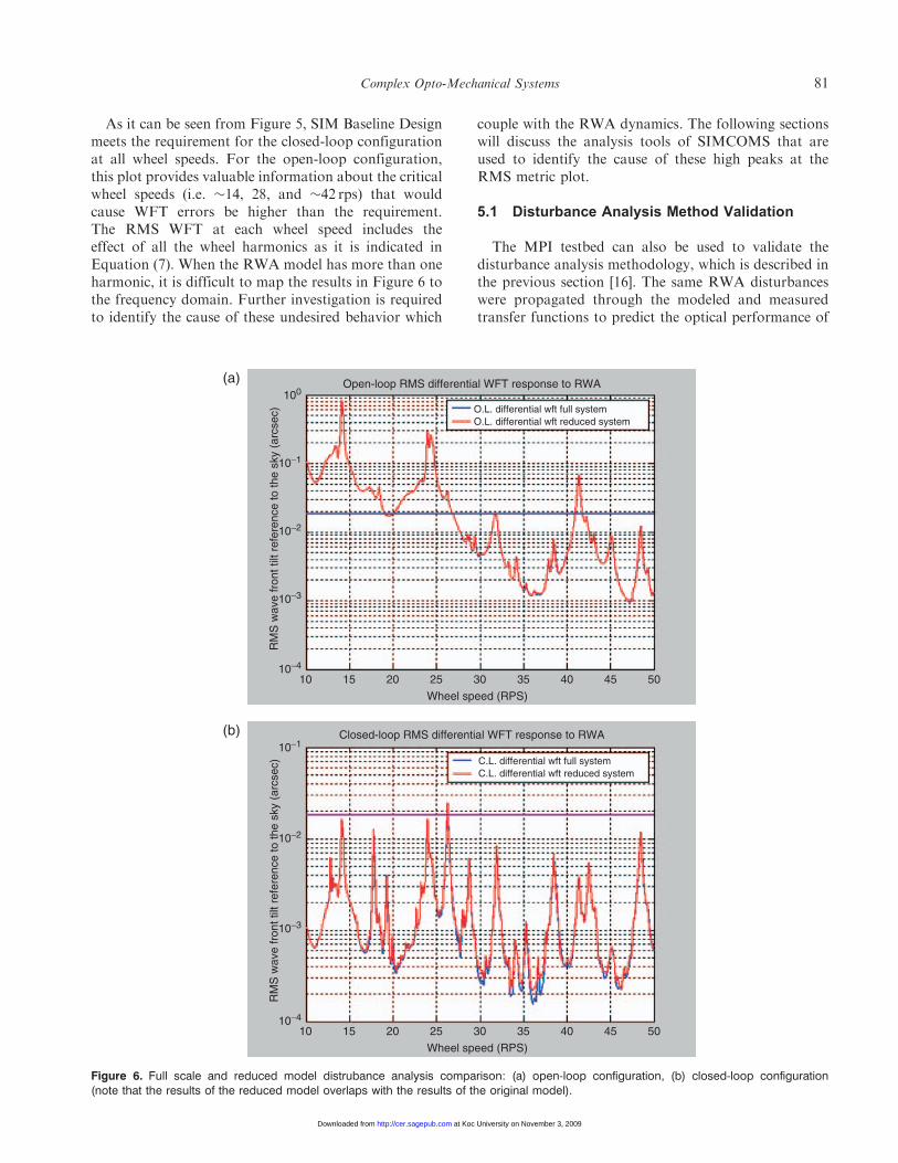
As it can be seen from Figure 5, SIM Baseline Designmeets the requirement for the closed-loop configurationat all wheel speeds. For the open-loop configuration,this plot provides valuable information about the criticalwheel speeds (i.e. �14, 28, and �42 rps) that wouldcause WFT errors be higher than the requirement.The RMS WFT at each wheel speed includes theeffect of all the wheel harmonics as it is indicated inEquation (7). When the RWA model has more than oneharmonic, it is difficult to map the results in Figure 6 tothe frequency domain. Further investigation is requiredto identify the cause of these undesired behavior which
couple with the RWA dynamics. The following sectionswill discuss the analysis tools of SIMCOMS that areused to identify the cause of these high peaks at theRMS metric plot.
5.1 Disturbance Analysis Method Validation
The MPI testbed can also be used to validate thedisturbance analysis methodology, which is described inthe previous section [16]. The same RWA disturbanceswere propagated through the modeled and measuredtransfer functions to predict the optical performance of
(a)
O.L. differential wft full systemO.L. differential wft reduced system
100
10−1
10−2
10−3
10−4
10
RM
S w
ave
fron
t tilt
ref
eren
ce to
the
sky
(arc
sec)
15 20 25 30
Wheel speed (RPS)
Open-loop RMS differential WFT response to RWA
35 40 45 50
(b)
C.L. differential wft full systemC.L. differential wft reduced system
10−1
10−2
10−3
10−4
10
RM
S w
ave
fron
t tilt
ref
eren
ce to
the
sky
(arc
sec)
15 20 25 30
Wheel speed (RPS)
Closed-loop RMS differential WFT response to RWA
35 40 45 50
Figure 6. Full scale and reduced model distrubance analysis comparison: (a) open-loop configuration, (b) closed-loop configuration(note that the results of the reduced model overlaps with the results of the original model).
Complex Opto-Mechanical Systems 81
at Koc University on November 3, 2009 http://cer.sagepub.comDownloaded from
the MPI testbed. At the same time, the actual opticalperformance of the instrument can be measured directlywhile the wheel is spinning on MPI. The modelpredictions were then compared with the actual(measured) optical performance of MPI, measuredwith the RWA mounted to MPI, to evaluate theaccuracy of the disturbance analysis method. The resultsshow that this method can accurately calculate theoptical performance of MPI when disturbance boundaryconditions are corrected with ‘force filters’ that dependon estimates of the interface accelerances of theRWA and the MPI structure to represent the coupledRWA–MPI interface.The actual optical performance measurement is not
feasible on the SIM spacecraft since the flight hardwarewill not be ready until the end of the implementationphase of the project. But instead, one can build anintegrated model of the SIM spacecraft using themodeling methodology presented in this article andapply the same disturbance analysis method to predictthe optical performance of the SIM instrument underthe same type of RWA disturbances as described in theprevious section.
6. Model Reduction & Disturbance Analysis withthe Reduced Model
Model reduction capability is also included in theSIMCOMS analysis module. The motivation behind
the model reduction is to reduce the computationalexpense in performing the further analysis. The goal is toreduce the size of the system while maintaining theimportant dynamics. The first step is to create abalanced realization of the state space system.The technique was introduced in the control communityby Moore [30]. We use MATLAB balancing function‘balreal’ [33]. The algorithm creates a system withidentical diagonal controllability and observabilitygramians. The criterion for a balanced system is thatboth the observability and controllability gramians arediagonal and equal.
The Gramian values (diagonal of Gramian matrix)that correspond to modes of low controllability/obser-vability can be removed from the model withoutsignificantly affecting the retained dynamics [34].SIMCOMS menus allow the user to select the desirednumber of states and also make a comparison betweenthe reduced model and the original one. In our case, thefirst 304 states corresponding to the largest singularvalues are retained. This reduced model is subsequentlyused for the discrete RWA disturbance analysis andthe results are compared. Figure 7(a) and (b) shows thecomparison of the RMS metric using the original andthe reduced model for the open-loop and closed-loopconfigurations, respectively. In both cases, the reducedmodel disturbance analysis overlaps with the results ofthe original model, which demonstrates that the reducedmodel captures all the significant dynamics to predictthe WFT performance.
100 101 102 1030
0.5
1
Frequency (Hz)
Nor
mal
ized
mod
al g
ains
1.14 2.88 6.85 6.89 12.4 13.5 14.1 14.3 14.3 240
0.5
1
Modal frequency (Hz)
Top
10
mod
al g
ains wft ol
(a)
(b)
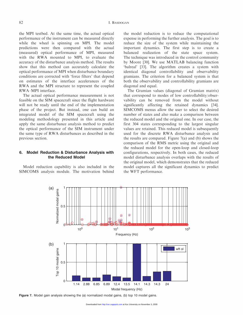
Figure 7. Model gain analysis showing the (a) normalized modal gains, (b) top 10 model gains.
82 I. BASDOGAN
at Koc University on November 3, 2009 http://cer.sagepub.comDownloaded from

7. Modal Gain Analysis
The modal gains or the modal participation factorsfrom the RWA disturbance input to WFT are calculatedas a function of frequency (Figure 8(a)). The equationfor the modal gains is derived in Ref. [35].
�2i ¼bib
Ti c
Ti ci
� �1=2
4�{!2i
ð8Þ
�i is the modal gain of the ith mode and the entries of thestate-space matrices are used to obtain bi, ci, �i, and !i.The first 10 critical modes that have the largest modalparticipation are shown in Figure 8(b). For the WFTperformance, the highest modal gains appear to beclustered between 1 and 24Hz where 14.1Hz has themaximum value. Further analysis is required to identifythe problematic component that causes the highest peakat 14.1Hz. Although modal gain approach providesthe information regarding the problematic frequencyrange, it only includes the state-space model of theopto-mechanical system and does not consider the effectof the disturbances. The ‘critical frequency analysis’ willbe presented in the following section.
8. Critical Frequency Analysis
The ‘critical frequency analysis’ tool is based on thebroadband disturbance model of the reaction wheel
disturbances, which was developed by Gutierrez [31].The stochastic broadband model is based on the discretefrequency model which was introduced in Section 5 andassumes that the wheel speed is a uniform randomvariable over the interval 10–50 rps. This approachfacilitates the broadband frequency analysis leading to afrequency domain model that can be propagatedthrough the SIM integrated model. WFT PSDs arestill calculated in the same way as shown in Equation (8)by convolving the transfer functions of the opto-mechanical model with the broadband PSDs of thecorresponding force or torque. But now the PSD ofthe WFT is a continuous function of the frequency[Figure 6(a)]. Figure 6(b) is the cumulative RMS and itis obtained by integrating under the PSD and taking thesquare root. The RMS error tends toward a value ofRMS¼ 0.065 arcsecond which is high above therequirement. As it can be observed from the figurealthough there are small jumps in the cumulative RMScurve between 1 and 24Hz, the biggest jump is at14.1Hz, which also agrees with the previous results fromthe ‘modal gain analysis.’
9. Strain Energy Analysis
The ‘strain energy analysis’ tool identifies the fractionof total strain energy due to component modes. Strainenergy is a measure of the deformation of the structureand it is proportional to stiffness. We can identifythe critical components that degrade the system
100 101 102 10310−10
10−5
Frequency (Hz)
PS
D (
arcs
ec/s
qrt(
Hz)
)
Differential WFT response to RWA (at detector)(a)
(b)
100 101 102 103
0.02
0.04
0.06
0.08
0.1
Frequency (Hz)
Cum
ulat
ive
RM
S (
arcs
ec)
OL
CL
WFT requirement
Figure 8. Critical frequency analysis showing the (a) PSD of differential WFT response, (b) cumulative WFT RMS.
Complex Opto-Mechanical Systems 83
at Koc University on November 3, 2009 http://cer.sagepub.comDownloaded from

performance by analyzing the fraction of total strainenergy at the given mode numbers (e.g., mode numbersare obtained based on the frequency sorting of the modeshapes) and/or frequency range utilizing the SIMCOMSplotting options. Figure 9 shows the strain energydistribution for different components of the SIMinstrument. If we concentrate on the frequency rangebetween 13 and 16Hz range, it can be observed that themain contributor to the total strain energy at 14Hzis the siderostat bay component. This analysis showsthat the problematic component at 14.1Hz is located atthe siderostat bay (Figure 10 – Note that there are eightsiderostat bays in the SIM instrument which explains theeight modes in the strain energy diagram clusteredaround 14Hz). The most critical component in the
siderostat bay is the siderostat mirror, which is one ofthe major optical components in the optical ray trace.Additionally, we used the animation capabilities ofthe SIMCOMS and verified that the 14.1Hz mode wasa rotational mode of the siderostat mirror about thex and z axes. Based on these results, we decided to focuson the siderostat mirror and perform a sensitivityanalysis on the structural parameters of the mirrorsupport to improve the performance.
10. Sensitivity Analysis
Determining sensitivity of design parameters canprovide useful information, especially when the system
14.1
Hz
13.6
Hz
13.5
Hz
1
Fra
ctio
n of
mod
al s
trai
n en
ergy
0.9
0.8
0.7
0.6
0.5
0.4
0.3
0.2
0.1
062 63 64 65 66 67
Mode number
PsspyPssmyBackpyBackmySolarMetroIsoDelayLSidero
68 69 70 71 72 73 74
14.2
Hz
14.2
Hz
14.2
Hz
14.2
Hz
14.3
Hz
14.3
Hz
14.3
Hz
15.5
Hz
15.8
Hz
15.9
Hz
Figure 9. Strain energy distribution for the different component modes.
Siderostat bay
Siderostat mirror
Siderostat mirror
x
z
y
Siderostat mirror mount
Figure 10. Siderostat mirror loacated at the Siderostat Bay component of the SIM Instrument.
84 I. BASDOGAN
at Koc University on November 3, 2009 http://cer.sagepub.comDownloaded from

does not meet the specified requirements. For systemswith many design parameters, sensitivity informationcan identify which parameters in the system are the mostsignificant. These parameters might be the focus ofredesign efforts that attempt to improve theperformance.
In SIMCOMS, the finite difference technique is usedto calculate the design parameter sensitivities.The design parameters are perturbed one at a time inthe finite element analysis, the state-space model isreconstructed for the perturbed system, the disturbanceanalysis is performed, and the new performance RMSvalue, �zi, is computed using the approach describedin [31]. The performance difference between theperturbed system and the original system is then dividedby the amount of change in the design parameter �p andthe sensitivity value is approximated. In order tocompare the sensitivities calculated with respect to theparameters of different units or magnitudes, normalizedvalues are computed as follows.
ð�zi perturbed��zi originalÞ=�zi originalð Þ
�p�p original
�% change in�zi% change inp
ð9Þ
The sensitivity analysis of the siderostat mirror mount isperformed for the following design parameters; Ixx, Iyy,Izz, the moment of inertia about the x-, y-, and z-axes,respectively.
Table 1 tabulates the sensitivities of physical para-meters for the siderostat mirror mount. Among thecomputed sensitivities, the greatest sensitivity belongsto Ixx, and Izz, the moment of inertias about the x- andy-axes. When disturbances are effective on the system,1% increase in the moment of inertia Ixx results in adecrease of 1.87% in the RMS performance of theinstrument. Similarly, 1% increase in the moment ofinertia Izz results in a decrease of 1.24% in the RMSperformance of the instrument. A decrease in the RMSvalue can be interpreted as improved performance forthe instrument. As expected, 1% increase in the momentof inertia Iyy does not change the results significantly.
Sensitivity information can provide useful informa-tion especially, when there are many design parametersto explore in the design space. Sensitivity information
can be used as a starting point for developing theisoperformance methodology, which was previouslystudied by de Weck and Miller [24]. Their methodologyis based on the idea of holding a performance metric orvalue of an objective function constant and finding thecorresponding contours to perform multidisciplinaryoptimization. However, the sensitivity analysis pre-sented in this study only focus on few design parametersand identifies which parameters should be the focus ofthe redesign. The redesign scenario presented in thefollowing section does not represent the optimalsolution.
11. Model Refinement and Redesign of theSiderostat Mirror Mount
Based on the above analysis, we update the mirrorparameters and stiffen the mirror mount and the firstfrequency of the siderostat mirror becomes 33Hz, whichwas originally at 14.1Hz. Updating is performed utilizingthe options in the SIMCOMS structural module withoutchanging the optics model. The disturbance analysis isrepeated for the open- and closed-loop configurationsusing the new model and the new WFT performance asa function of wheel speed plot, which can be seen inFigure 11. As it can be observed from the figure, theWFTrequirement can be met even with the open-loopconfiguration, which relaxes the control design for thepointing control system.
Although the preliminary results show that the SIMinstrument can meet the requirements for open-loopconfiguration, detailed analysis is required to verify thisconclusion. Some of the modeling assumptions have tobe revisited and validated by supporting experimentalstudies.
12. Conclusion and Future Studies
We have demonstrated an end-to-end performanceanalysis and a virtual redesign process of SIM instru-ment using the web-based modeling and simulationenvironment, SIMCOMS. SIMCOMS is a concurrentdesign tool for predicting the performance ofcomplex opto-mechanical systems especially whenexperimental testing is not viable or expensive. Itintegrates control, structural, and optic models topredict the optical performance of the instrumentunder the effect of disturbance sources. It can supporta cross-functional team to simulate and design complexopto-mechanical systems concurrently in the earlydesign stage.
The analysis and simulation modules of SIMCOMSallow testing various design scenarios very efficientlyto improve the instrument performance. Engineers and
Table 1. Sensitivity analysis results.
Design parametersof the siderostatmirror support
WFT performance(%)
Moment of inertia, Ixx �1.87Moment of inertia, Iyy 0.04Moment of inertia, Izz �1.24
Complex Opto-Mechanical Systems 85
at Koc University on November 3, 2009 http://cer.sagepub.comDownloaded from

scientists can run ‘what-if’ scenarios to test the validity ofdeveloped models. SIMCOMS provides a shared plat-form for distributed engineers and scientists to work onthe same problem together. The web-based architectureprovides flexibility and robustness that allows the accessof multiple users at the same time.Moreover, the users donot need local computers with high computationalcapabilities to use SIMCOMS. All the computationsare performed by a computational engine at the serversite. However, results can be visualized, saved, printed, orstored locally. SIMCOMS could be also used as anarchive of the various design models until the design ismature. Although, the SIMCOMS is designed to fit thesimulation needs of the complex opto-mechanical spacesystems, the philosophy and the performance predictionapproach and analysis tools are suitable for othermechanical systems as well. The architecture ofSIMCOMS is flexible and can be easily linked to otherapplication programs and utilized to perform collabora-tive design projects between various disciplines.
Acknowledgments
The authors kindly acknowledge the technical supportof Olivier De’Weck from MIT, Strategic EngineeringLaboratory and Linh Phan from NASA-Jet PropulsionLaboratory/California Institute of Technology duringthe course of this work.
References
1. Heim, J. et al. (1999). TRW Process Improvements forRapid Concept Designs, In: 1999 IEEE AerospaceConference Proceedings, Snowmass at Aspen, Colorado.
2. Wall, S. (1999). Reinventing the Design Process: Teams andModels, In: International Astronautical Federation SpecialistSymposium on Novel Concepts for Smaller, Faster and BetterSpace Missions, April, Redondo Beach, CA.
3. Sanders, G. (2002). The Sky’s the Limit for CIEL, BSSWorld, 3(13).
4. Smith, P. (2001). Concurrent Design at AerospaceCorporation, Crosslink Magazine, Winter.
5. Bandecchi, M., Melton, B., Gardini, B. and Ongaro, F.(2000). The ESA/ESTEC Concurrent Design Facility,In: Proceedings of of EuSEC 2000, ISBN 3-89675-935-3,Munich, Germany.
6. Osburg, J. and Mavris, D. (2005). A Collaborative DesignEnvironment to Support Multidisciplinary ConceptualSystems Design, SAE Transactions, 114: 1508–1516.
7. Chang, -C., Lu, F. and Liu, X.F. (1999). WWW-BasedCollaborative System for Integrated Design andManufacturing, Concurrent Engineering: Research andApplications, 7(4): 319–334.
8. Chang, K.-H., Silva, J. and Bryant, I. (1999). ConcurrentDesign and Manufacturing for Mechanical Systems,Concurrent Engineering: Research and Applications, 7(4):290–308.
9. Senin, N., Wallace, D.R. and Borland, Nicholas (2003).Distributed Object-Based Modeling in DesignSimulation Marketplace, ASME, Journal of MechanicalDesign, 125(2): 2–13.
Open-loop
Open- & closed-loop WFT performance
100
10−1
10−2
10−3
10−4
10−5
RM
S w
ave
fron
t tilt
ref
eren
ce to
the
sky
(arc
sec)
10 20 30 40 50 60
Wheel speed (RPS)
O.L. w/gimbal 33C.L. w/gimbal 33
Closed-loop
Figure 11. Open- and closed-loop WFT performance after the siderostat mirror mount is redesigned.
86 I. BASDOGAN
at Koc University on November 3, 2009 http://cer.sagepub.comDownloaded from
10. Kalsi, M., Hacker, K. and Lewis, K. (2001). AComprehensive Robust Design Approach for DecisionTrade-offs in Complex Systems Design, ASME, Journal ofMechanical Design, 123(1): 1–10.
11. Chen, W. and Lewis, K. (1999). A Robust DesignApproach for Achieving Flexibility in MultidisciplinaryDesign, AIAA Journal, 37(8): 982–990.
12. Ollinger, G.A. and Stahovic, T.F. (2004). Redesign IT-AModel-based Tool for Managing Design Changes, ASME,Journal of Mechanical Design 126(2): 208–216.
13. Milman, M.H., Briggs, H.C., Ledeboer, W., Melody, J.W.,Norton, R.L. and Needels, L. (1995). Integrated Modelingof Optical Systems User’s Manual, Release 2.0, JPLD-13040 (Internal Document).
14. Redding D. (1992). Controlled Optics Modeling PackageUser Manual, Release 1.0, JPL D-9816 (InternalDocument)
15. Basdogan, I., Dekens, F. and Neat, G.W. (1999). AnIntegrated Model Validation Study of the Wave Front Tip/Tilt System Using the Micro-Precision InterferometerTestbed, In: Proceedings of 1999 IEEE AerospaceConference, April, Snowmass, CO.
16. Basdogan, I., Elias, L., Dekens, F. and Sievers, L. (2007).Predicting the Optical Performance of the SpaceInterferometry Mission Using a Modeling, Testing, andValidation Methodology, ASME Journal of Vibration andAcoustics, 129(2):148–157.
17. Colavita, M.M. Shao, M. and Rayman, M.D. (1993).Orbiting Stellar Interferometer for Astrometry andImaging,’’ Applied Optics, 32(10): 1789–1797.
18. Shao, M. and Wolf, D.M, Orbiting Stellar Interferometer,In: Proceedings of SPIE Symposium on SpaceborneInterferometry, April, Orlando, FL, Vol. 2447, pp. 228–239.
19. Yu, J. (2001). The SIM Interferometer, JPL InterofficeMemorandum, Pasadena, California.
20. Harrison, M. and other contributors (1997). Tcl/Tk Tools,O’Reilly & Associates, Inc.
21. Morse, W. (1994). A Tcl/Tk and Expect Tutorial, Houston,TX: World Wide Technology Conference.
22. Gundavaram, S. (1996). CGI Programming on the WorldWide Web, O’Reilly & Associates, Inc.
23. http://www.tcl.tk/software/plugin/whatis.html
24. de Weck, O.L. and Miller, D.W. (2002) MultivariableIsoperformance Methodology for Precision Opto-Mechanical System, In: 43rd AIAA/ASME/ASCE/AHSStructures, Structural Dynamics, and MaterialsConference, Paper AIAA-2002–1420, 22–25 April,Denver, Colorado.
25. Basdogan, I., Grogan, R., Kissil, A., Sigrist, N. and Sievers,L. (2000). Preliminary Optical Performance Analysis of theSpace Interferometer Mission Using an IntegratedModeling Methodology, In: Proceedings of the 6thBiennial Symposium on Active Control of Vibration andNoise, The 2000 International Mechanical EngineeringCongress and Exposition, November, Orlando, FL.
26. Shabana, A. (1991). Theory of Vibration, Vol. 2, Springer-Verlag, New York, NY.
27. Kwon, Y.W. and Bang, H. (1997). The Finite ElementMethod using MATLAB, CRC Press Inc, Boca Raton,Florida.
28. Masterson, R. (1999). Development and Validation ofEmpirical and Analytical Reaction Wheel DisturbanceModels, Master’ thesis, Massachusetts Institute ofTechnology.
29. Melody, J.W. (1995). Discrete-frequency and BroadbandReaction Wheel Disturbance Models, InterofficeMemorandum 3411-95-200csi, Jet Propulsion Laboratory.
30. Moore, B. (1981). Principal Component Analysis in LinearSystems: Controllability, Observability and ModelReduction, IEEE Transactions on Automatic Control,AC-26: 17–31.
31. Gutierrez, H.L. (1999). Performance Assessment andEnhancement of Precision Controlled Structures DuringConceptual Design, PhD thesis, Massachusetts Institute ofTechnology.
32. Goullioud, R., Dekens, F.G. and Neat, G.W. (2000).Microprecision Interferometer: Scoreboard on TechnologyReadiness for the Space Interferometer Mission, In:Proceedings of SPIE Interferometry in Optical Astronomy,Vol. 4006.
33. Hatch, M.R. (2000). Vibration Simulation Using Matlaband Ansys, Chapman & Hall/CRC, Boca Raton, Florida.
34. Laub, A.J., Heath, M.T., Paige, C.C. and Ward, R.C.(1987) Computations of System BalancingTransformations and Other Applications of SimultaneousDiagonalization Algorithms, IEEE Transactions onAutomatic Control, AC-32: 115–122.
35. Gregory, C.Z. (1984). Reduction of Large Flexible ModelsUsing Internal Balancing Theory, Journal of Guidance,Control, and Dynamics, 7(6): 725–732.
Ipek Basdogan
Ipek Basdogan, PhD, is anAssistant Professor at KocUniversity Istanbul, Turkey inthe Department of MechanicalEngineering. She received herPhD in mechanical engineeringfrom University of Illinois atChicago in 1997. During herPhD, she worked at ArgonneNational Laboratory-Advanced Photon Source.Before joining Koc University
she worked as a senior member of technical staff inGuidance and Control Analysis Group at the JetPropulsion Laboratory between the years of 1997 and2002. Her research interests include modeling of opto-mechanical and electro-mechanical systems, dynamicsand structural analysis, vibration control, vibro-acousticanalysis, and testing.
Complex Opto-Mechanical Systems 87
at Koc University on November 3, 2009 http://cer.sagepub.comDownloaded from