condition assessment evaluation & planned design improvements … · condition assessment...
TRANSCRIPT
Condition Assessment Evaluation
& Planned Design Improvements
for the Cowes Generator
William G. Moore, P.E.
National Electric Coil
U.S.A.
ABSTRACT
The Cowes unit is located on the Isle of Wight, off the southern coast of England. It is an 87,000
kVA air cooled generator, originally manufactured by Parsons. The generator suffered a failure
when a rotor slot wedge failed in fatigue and spun out of the rotor. The wedge hit a lube oil line
at the exciter end of the machine, which spewed hot oil over the area. A fire started which
severely damaged the exciter and exciter end of the generator. The exciter rotating shaft suffered
a severe bend due to the extreme heat. The exciter end of the generator rotor was also
significantly damaged due to the fire. Additional slot wedges that exited the slot did further
damage to the stator core and the stator winding. Both generator bearings wiped due to the
subsequent failure of the lube oil system.
An extensive evaluation of all the failed components was conducted, with recommendations for
repair or replacement. This paper will describe the evaluation methodology for deciding on
which components could be repaired or needed to be replaced. Hardness mapping, dimensional
verification, and visual inspection will all be discussed and presented, with very vivid pictures of
the damage and rebuild process. Rotor shaft repair / replacement options will be discussed.
Exciter replacement alternatives, such as the choice between going back with a similar brushless
2
system, or changing to a static excitation system, along with the pro’s and con’s of each, will be
presented. Planned design improvements, as part of the rebuild process, are described where
possible. Due to the temperature and extent of the fire, and the subsequent damage, the entire
exciter needed to be replaced, along with the stator core, stator winding, rotor forging, rotor
winding, and most of the components of the rotor.
This paper would be useful for plant owners, insurance investigators, or other consultants that are
faced with assessing plant component damage. Alternatives and choices made as part of this
rebuild will help others in similar situations make more informed decisions about repairs and or
replacements.
DESCRIPTION OF DAMAGE
Background of Failure
There are two 70 MW, 11.8 kV Parson’s generators, placed in service in the early 80’s at the
Cowes Power Station on the Isle of Wight. Each generator has a gas turbine at each end. One
end has a brushless exciter, between the generator and one of the gas turbines. One of the two
generators on site had a rotor slot wedge failure after nearly 20 years of operation. The wedge
stress was excessive due to the stress concentration in the fillet of the wedge. When the wedge
failed in fatigue, it was thrown out of the slot due to rotational forces. That wedge, or
subsequent wedges or copper were thrown out of the machine and severed a lube oil line near the
exciter. A fire started in the lube oil pump and exciter area and burned for some time, causing
extensive damage to the exciter, generator rotor shaft, and stator end turns. The stator core was
damaged throughout by wedges and copper that were thrown out of the slot.
After this failure, the other, identical unit, had its rotor pulled out and wedges inspected. The
existing wedges were replaced with a new, lower stress design, and the unit was put back in
service. Due to logistical and financial constraints, as well as excess capacity, the failed
generator was not dismantled for several years, until the start of this project. The evaluation of
the generator and exciter damage, as well as the consideration of repair and replace decisions, are
the subject of this paper.

3
Rotor and Exciter
An initial inspection was done of the rotor as it sat at the owner's site. Based on visual
inspection alone, it wasn’t clear if the rotor forging could be reused or not. It was recommended
that a re-qualification program be developed to determine the suitability of repairing the rotor
and returning it back to service. Tests and evaluations, such as TIR (Total Indicator Runouts) and
concentricity checks, hardness mapping, metallurgical replicas, and material sampling with
Charpy and elongation checks, would be done. Gages would be made to check all the slots.
The highest degree of concern would be the material properties and integrity of the generator
rotor forging. The exciter end of the rotor forging was in close proximity, if not at the center of
the fire. Figure 1 shows the exciter end of the generator rotor and is shown below.
Figure 1: Exciter end of the generator rotor.

4
The exciter had a severely bent shaft, measurable in inches. Several of the coupling bolts in the
generator’s exciter end coupling were severely bent from the heating and impossible to remove
from the generator rotor coupling.
Shaft seals were damaged and the journals would have to be reground, if the forging could be
saved.
New seals and bearings would be necessary. It was felt that it might be possible to re-use the
bearing casing and pedestals. There was no obvious distortion of the rotor shaft or couplings.
The connection coupling was damaged and would need to be replaced. A photo of the bent
exciter shaft is shown below.
Figure 2: Damage to the exciter from the fire was extensive..
5
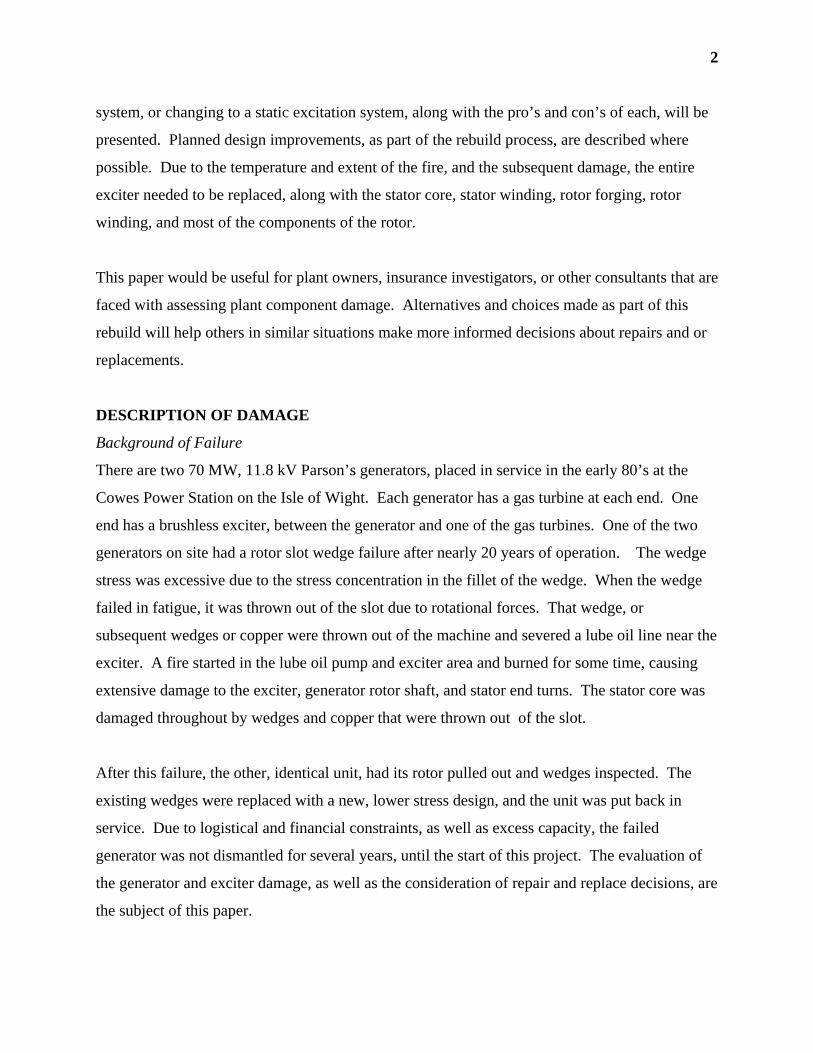
Stator Core and Winding
Due to the damage from the expelled rotor slot wedge and rotor copper, as well as the heat from
the fire, it was readily apparent that the stator winding and core had to be replaced. The damage
to the stator core, as shown in Figure 3, was not limited to just one end of the stator. Therefore, a
partial restack was not possible. The damage was found throughout the entire core. There were
no obvious signs of melting of the core pressing plate, key bars, or other components. There
were no obvious signs of paint blistering on these parts, but the winding had areas of heavy
accumulations of soot, and the insulating clip caps at the ends of the bars had obviously melted,
as shown in Figure 4.
Figure 3: Stator core laminations were displaced due to heat and mechanical pressure over the length of the
slot.

6
Figure 4: Soot covered exciter end of the generator stator winding is shown above. Notice the heat damage to
the insulating clip caps at the ends of the bars.
The next section of this paper discusses in more detail the evaluation of the components and
possible repair or replace options that were considered.
ENGINEERING ASSESSMENT, REPAIR AND DESIGN IMPROVEMENTS
Rotor Shaft
In the evaluation phase, it was determined that reusability of the rotor forging was the single
largest uncertainty of this project, and would cause the greatest price differential depending upon
the workscope that was needed. The primary concern about the rotor shaft was its “straightness”
and its current material properties. Initially, several repair or replace options were considered.

7
These are listed below.
• Reuse the rotor forging “as is”
• Perform a weld overlay of the rotor shaft end and then re-machine to correct any
distortion.
• Straighten the rotor shaft end
• Cut off the end of the rotor shaft and replace it
• Manufacture a new rotor forging
It was proposed by NEC and accepted by the customer, that a methodical series of rotor forging
qualifications and evaluations would be done to determine the necessary workscope for the rotor
forging shaft. This step by step evaluation approach to re-qualify and possibly reuse the rotor
would provide the highest degree of reliability at the minimum cost. The rotor would be
disassembled, first, by removing the fan hubs, retaining rings and the copper windings. The
following evaluation steps would then be done:
1. Perform Visual Examinations and Inspections of the entire rotor for signs of overheating
to the point of melting and tooth damage from the slot wedges. Areas of discoloration,
blackening, or distorted metal could be signs of overheating. Damaged areas would be
documented in writing and with photographs.
2. Perform Rotor Run-outs in the lathe on all diameters of the rotor forging using specified
acceptance criteria guidelines.
3. Do Perpendicularity Checks on the coupling faces (+ / - 0.0254 mm, + / - 0.001 inch).
This would be done by axial run-outs on the coupling faces, at various radial locations.
4. Perform Diametral Checks at each runout location at 180 degree intervals. Egg-shaped
protrusions, or depressions would be cause for material disqualification.
5. Conduct Hardness Mapping of the exciter end coupling face, rim outer diameter,
outboard seal area, exciter end journal, inboard seal area, and exciter end shaft extension.
Hardened areas, with Brinnel Hardness numbers greater than 100 over the average value
at samples on the non-exciter end, would be cause for material disqualification.
6. Apply Nital Etch Solution (alternative is Ammonium Persulfate) on discovered hard spots
for visual determination of the total surface area affected by overheating.
8
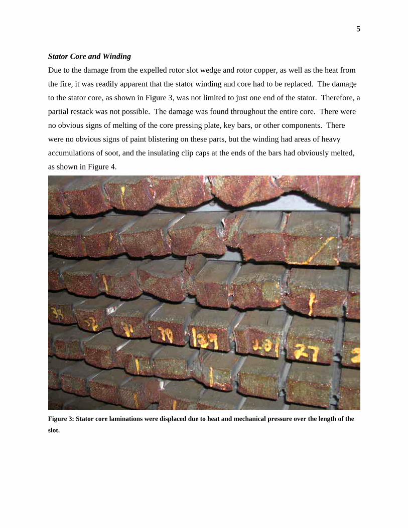
7. Measure Slot Width with machinists parallels. Take measurements at every slot, two
axial locations; one near the turbine end and one near the exciter end. A variance greater
than + / - 0.005 inches would be cause for further investigation.
If all the above measurements and checks were satisfactory, a boresonic exam would be done to
prove the rotor bore and interior are acceptable for reuse. Depending upon the findings above,
the following repair options would then be considered.
• Reuse of the rotor “as is:” Of course, this option would be the most desirable, but it
would be based on a successful evaluation utilizing all the re-qualification criteria as
described above.
• Perform a weld overlay of the rotor shaft end and then re-machine to correct any
distortion: This repair option would be used if there were only minor dimensional
irregularities due to the overheating event. These irregular areas would have a weld
overlay, then a re-machining, all of which could be done in the field. This option would
include some machining for weld preparation and to remove some localized damaged
material from the overheating event. Final re-machining of the shaft end would put the
rotor back to its original design configuration.
• Straighten the rotor shaft end: This option would be utilized if significant bending of the
exciter end shaft was apparent. The process is a combination of shaft end heating,
welding, and straightening. This option would straighten a bent or bowed shaft end,
remove and repair any damaged material, repair a deformed or damaged coupling and
return the rotor to its original design configuration.
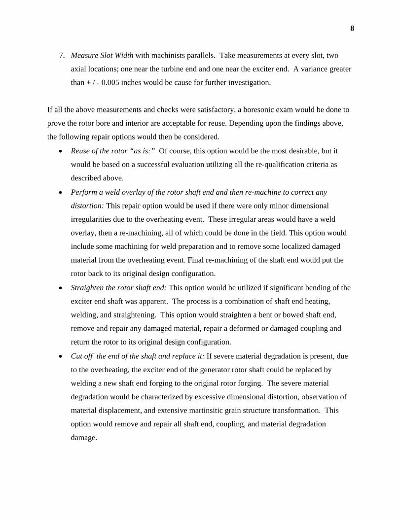
• Cut off the end of the shaft and replace it: If severe material degradation is present, due
to the overheating, the exciter end of the generator rotor shaft could be replaced by
welding a new shaft end forging to the original rotor forging. The severe material
degradation would be characterized by excessive dimensional distortion, observation of
material displacement, and extensive martinsitic grain structure transformation. This
option would remove and repair all shaft end, coupling, and material degradation
damage.

9
• Manufacture of a new rotor shaft forging: This option would be recommended if material
degradation and physical damage to the rotor shaft is severe and beyond one of the repair
options listed previously. The new forging, if required would be procured to the latest
non-destructive evaluation standards. Machining drawings would be made to
engineering specifications.
Rotor Forging Evaluation Results
Rotor hardness tests were conducted over the entire length of the rotor shaft forging, particularly
at the heat damaged exciter end. Two locations were chosen, 180 degrees apart, at each major
diameter of the rotor. Figure 5 shows the overall geometry of the rotor, and the hardness reading
results in Brinnel. Surprisingly, no hardness locations were observed, and, even at the heat-
damaged end, the overall criteria of a 100 point hardness differential was not violated. Hardness
readings ranged from about 250 BHN to about 200 BHN, which is well in the expected range for
this material. As a result of these tests, no etching was done on any specific area.
Figure 5: Hardness results in Brinnel.
Slot width measurements were taken at two axial locations, in each and every slot, because even
small variations in slot width can necessitate extensive repair or even replacement of the forging.
It was suspected that substantial warping of the slot width had occurred at the exciter end, due to
displacement of the rotor teeth from the excessive heat. Surprisingly, once again, significant
variation in slot width was not observed in any of the slots. A detailed summary of the
measurements is shown in Figure 6.
10
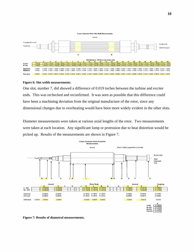
Figure 6: Slot width measurements.
One slot, number 7, did showed a difference of 0.019 inches between the turbine and exciter
ends. This was rechecked and reconfirmed. It was seen as possible that this difference could
have been a machining deviation from the original manufacture of the rotor, since any
dimensional changes due to overheating would have been more widely evident in the other slots.
Diameter measurements were taken at various axial lengths of the rotor. Two measurements
were taken at each location. Any significant lump or protrusion due to heat distortion would be
picked up. Results of the measurements are shown in Figure 7.
Figure 7: Results of diametral measurements.

11
These diametral measurements did not show any significant distortion of the rotor. Even the
generator coupling at the exciter end, which experienced the most heat, had only a 0.010 inch
difference between the two measurements.
Runout readings were taken with the rotor in the lathe. This measurement would indicate if the
rotor shaft is bent in any manner. Results are summarized in Figure 8. Total Indicator Runout
(TIR) readings showed a sharp bend in the rotor shaft near the exciter end of the generator rotor.
The coupling, for instance had a total TIR of 0.310 inches in the radial direction. Results of the
axial runouts taken on the face of the coupling were excessive also, with readings of 0.176 inches
near the outer diameter rim of the coupling. These measurements clearly indicated a significant
bend in the rotor shaft. The repair method would require either the removal of the shaft end and
re-welding or the complete replacement of the rotor shaft.
Figure 8: Results of TIR readings.
Due to the large amount of distortion to the end of the rotor, consideration of the overall price of
a weld repair option, and taking into account the complex process control required to ensure

12
integrity of a weld repair option, NEC recommended a new rotor forging. The new forging
would have improved material properties over the original forging, and would be re-engineered
to match the dimensions of the original rotor.
Rotor Field Winding/Coils
Visual inspection of the rotor coils no significant distortion of the end turns. Signs of copper
turn melting were not evident either. Several top turns were displaced, possibly due to the
removal of the retaining ring. A hardness check of an existing copper turn on the non-exciter
end showed the copper to be of adequate hardness. The turn insulation consisted of a rubberized
material, coated onto each turn. In practice, this type of insulation material has been very
difficult to completely remove from the rotor turns. This fact, coupled with some minor
distortion of copper top turns, new copper coils were recommended and accepted.
Rotor Wedges
The existing rotor wedges were analyzed by classical and finite element methods. The analysis
was performed at both operating speed (3000 rpm) and 20% over speed (3600 rpm). The
maximum bending stress in the wedge was 356 MPa (51.6 ksi) and the shear stress was 73.7
MPa (10.7 ksi). Based on 7075-T6 Aluminum, with a tensile yield strength of 505 MPa, the
factor of safety on yield was 1.4 (bending stress)
In addition to other details, NEC proposed that the new rotor design include wedges with an
increased radius of 3 mm at the shoulder. Incorporating this feature would increase the fatigue
life of the wedges. Based on 7075-T6 Aluminum, the fatigue life would increase 60 times, to 32
million cycles, well beyond the low-cycle fatigue range.
An ANSYS Finite Element Model was created to analyze the stresses in the old and new wedge
designs. The model incorporated displacement of the rotor body at its end, as well as shrink fit
from the retaining ring in the same area. An example of one of the stress plots of the wedges is
shown below. The high stress concentration in the fillet radius of the wedge is clearly visible, as
indicated by the bright red area.

13
Figure 9: Graphic representation of the results of the ANSYS Finite Model analysis.
Rotor Fan Blades
Only two original fan blades were available after the generator failure. New rotor fan blades
were manufactured to fit the fan rings at each end of the generator rotor. The original design,
including the material and exact geometry, was re-engineered to provide full ventilation and
mechanical performance. The tapered and twisted configuration of the blade was duplicated by
using a sophisticated laser beam tracker that replicates the exact point on the blade into a
CAD/CAM tool. The blades were machined to original blade dimensions, including the blade
and the root.
Rotor End Rings (Retaining Rings)
New 18Mn18Cr retaining rings were manufactured at the customer’s request. The original rings
were magnetic material. The original design of the rings included a bayonet style attachment to
the rotor. This design was changed to a conventional snap ring attachment, which facilitates
removal of the rings, if necessary, in the future.
14
Other Rotor Components
Other rotor components were replaced as part of the standard rotor refurbishment and rewind
process. This, of course, included all new insulation material.
Exciter
Since the exciter was a total loss, two options were considered to completely replace the exciter.
The first was a direct replacement of the existing exciter, with the same configuration and
function as the original one. The second option was replacement with a static excitation system
that would provide the same function as the original excitation equipment. A replacement
exciter shaft, identical to the original would be utilized. The shaft would incorporate slip rings
that will feed the current through brushes to the generator rotor. Both options are more fully
described below.
• Replacement with a New Brushless Exciter Arrangement: The proposed replacement
rotating rectifier for the generator would be designed and manufactured to duplicate the
original equipment electrically and mechanically. It would be rated to match the existing
conditions of the generator and would include the following features:
o Shaft length from generator to clutch coupling faces
o Coupling pilot fits and bolting configuration
o Electrical connections to the generator
o Permanent Magnet Generator (PMG) output and electrical interface to the existing
Automatic Voltage Regulator (AVR)
o Diodes and Fuses identical to those in the existing Rotating Rectifier.
o An alternator with the same output as the original alternator and capable of
producing the exciter output in combination with the diodes
o A six-pole alternator stator designed to work identically as the original
o A bearing and pedestal design and manufacture providing the same rotor
dynamics as the original
o A housing and base providing the same functional capabilities as the originals
o All materials equal or better than the originals from a functional standpoint
o An overall arrangement duplicating the form, fit and function of the original
rotating rectifier.

15
In addition to geometrically duplicating all the components, analyses would be performed
on each component to assure it can perform reliably over the expected life of the
replacement rotating rectifier. Material selections and design details, such as the fits
between adjacent parts, would be analyzed with respect to the appropriate disciplines.
The disciplines involved include the following:
o Structural, to assure materials are not overstressed
o Electrical/thermal, to assure operating temperatures will be within guaranteed
limits.
o Mechanical, to assure that the fit up between all interfaces will be stable at
operating conditions.
o Electrical, to assure the rotating rectifier is compatible with the AVR and capable
of providing the correct excitation to the generator at normal and upset conditions.
o Heat transfer and ventilation, to assure that the mechanically and electrically
generated losses can be dissipated without causing excessive temperatures to any
rotating rectifier component.
Although the objective is to duplicate the original components, design changes would be
made if the analyses indicate that they will improve the components reliability,
maintainability and/or functionality providing there are no adverse effects.
• Replacement with a new Static Excitation System: This option would incorporate a
Digital Exciter System, consisting of a digital excitation controller, fan-cooled rectifier
bridge assembly, and power potential transformer (PPT) rated to match customer
requirements. The system would be mounted and wired and tested in a NEMA 1 cubicle,
complete with accessories. The system would utilize a new exciter shaft with slip rings
installed for current feed into the generator rotor. An enclosure would surround the shaft
and slip ring assembly, similar to the original exciter enclosure. The existing AVR
system would be replaced by the Digital Exciter System. The generator would have
black start capability with this system. Below, Figure 10 shows a solid model drawing of

16
the new exciter connecting shaft and slip rings. In the drawing, the new slip rings and
radial conductor leads are clearly visible to the left of the figure.
Figure 10: Solid model drawing of the new exciter connecting shaft and slip rings.
Static Excitation Option Selected
The static excitation option offered a significantly lower price, as well as the promise of less
maintenance. It was chosen as the best alternative for the replacement of the exciter.
Stator Core, Winding and Frame
As mentioned earlier in this paper, visual inspection of the stator core revealed significant
displacement and physical damage to the stator core throughout the length of the machine. Based
on this inspection, it was obvious that there was no need to perform stator core qualification
tests, such as an EL CID test or a Core Loop Test, to determine shorting of the iron laminations.
Since the entire core had to be replaced, a new stator winding was also required. Tests for
generator frame straightness and squareness were done, using laser guided levels and squares to
verify reusability of the frame. Straightness measurements were taken on the face of both frame
ends, and down the length of each side of the frame. No significant deviation, distortion or
warping was found in the stator frame, so the frame was determined to be suitable for reuse.

17
New stator core laminations were manufactured using low loss silicon steel. The generator was
transported across the channel to another power plant site, where crane and other service
accessibility was much better. The generator was stripped, restacked and rewound at this new
location, and then transported by transport back to the Isle of Wight.
The new stator winding incorporated a 540 degree Roebel transposition in the slot portion, but
otherwise essentially duplicated the original design configuration, since no uprate was required.
Ripple springs were incorporated to improve long lasting wedge tightness and to maintain the
coil tight and resist steady state slot pounding forces over time. Bar manufacturing processes,
and all electrical testing was performed based on strict quality control standards and according to
customer requirements.
SUMMARY AND CONCLUSIONS
The generator suffered a major failure due to a cracked rotor slot wedge. This one failed wedge
resulted in significant damage to the entire generator, requiring replacement of the rotor forging,
rotor winding, retaining rings, stator core, stator winding, and both bearings.
This paper provides an overall summary of the entire engineering review and evaluation of the
damage, and of the usability of the individual components, such as the rotor forging, exciter,
stator core and the stator winding.
Despite the extensive rebuild of most of the major components of the generator, this option was
still the most attractive as compared to a new generator or a complete replacement generator.
A systematic, engineering, methodical approach to the re-qualification of all components,
minimized cost to the project, and provided the best solutions and options for repair and
replacement.