conductive flooring for hospital operating rooms
TRANSCRIPT

NBS MONOGRAPH 11
Conductive Flooring for
Hospital Operating Rooms

THE NATIONAL BUREAU OF STANDARDS
Functions and Activities
The functions of the National Bureau of Standards are set forth in the Act of Congress, March
3, 1901, as amended by Congress in Public Law 619, 1950. These include the development and
maintenance of the national standards of measurement and the provision of means and methods for
making measurements consistent with these standards; the determination of physical constants and
properties of materials; the development of methods and instruments for testing materials, devices,
and structures; advisory services to government agencies on scientific and technical problems; in-
vention and development of devices to serve special needs of the Government; and the development
of standard practices, codes, and specifications. The work includes basic and applied research,
development, engineering, instrumentation, testing, evaluation, calibration services, and various
consultation and information services. Research projects are also performed for other government
agencies when the work relates to and supplements the basic program of the Bureau or when the
Bureau's unique competence is required. The scope of activities is suggested by the listing of
divisions and sections on the inside of the back cover.
Publications
The results of the Bureau's work take the form of either actual equipment and devices or pub-
lished papers. These papers appear either in the Bureau's own series of publications or in the journals
of professional and scientific societies. The Bureau itself publishes three periodicals available from
the Government Printing Office: The Journal of Research, published in four separate sections,
presents complete scientific and technical papers; the Technical News Bulletin presents summaryand preliminary reports on work in progress; and Basic Radio Propagation Predictions provides
data for deternnning the best frequencies to use for radio communications throughout the world.
There are also five series of nonperiodical publications: Monographs, Applied Mathematics Series,
Handbooks, Miscellaneous Publications, and Technical Notes.
Information on the Bureau's publications can be found in NBS Circular 460, Publications of the
National Bureau of Standards ($1.25) and its Supplement ($1.50), available from the Superintendent
of Documents, Government Printing Office, Washington 25, D.C.

UNITED STATES DEPARTMENT OF COMMERCE • Frederick H. Mueller, Secretary
NATIONAL BUREAU OF STANDARDS • A. V. Astin, Director
Conductive Flooring for Hospital Operating Rooms
Thomas H. Boone, Francis L. Hermach, Edgar H. MacArthur, and Rita C. McAuliff
Reprinted from the Journal of Research of the National
Bureau of Standards—C, Engineering and Instrumentation,
Vol. 63C, No. 2, October-December 1959.
National Bureau of Standards Monograph 11
Issued March 21, 1960
For sale by the Superintendent of Documents, U.S. Government Printing Office
Washington 25, D.C. - Price 20 cents

ContentsPage
1. Introduction - 1
2. Scope of investigation 1
3. Description of flooring samples 1
4. Factors influencing the electrical resistance 34.1. Age 34.2. Humidity 34.3. Surface moisture 44.4. Service 4
5. Factors influencing the determination of resistance 5
5.1. Applied voltage 55.2. Time 55.3. Contact resistance 65.4. Electrodes 7
5.5. Frequency 85.6. Instruments 8
6. Electrostatic tests 97. Nonelectrical properties 10
7.1. Indentation 107.2. Scratch resistance 117.3. Slipperiness 117.4. Scrubbing 127.5. Water absorption 137.6. Stain resistance 13
8. Summary and conclusions 139. References 15
10. Appendix A. Excerpts from the 1958 edition of NFPA publication No. 56,
Recommended safe practice for hospital operating rooms 15
11. Appendix B. Four-terminal method of measuring contact and internal resis-
tivities 1612. Appendix C. Calculation of resistance from contact and internal resistivities 16
31

Conductive Flooring for Hospital Operating Rooms
Thomas H. Boone, Francis L. Hermach, Edgar H. MacArthur, and Rita C. McAuliff
(July 9, 1959)
Characteristics and performance of available types of conductive flooring materialswere investigated in the laboratory. The study showed that the electrodes and instrumentsused to measure the floor greatly affected the measured resistance, but that the methodspecified by the National Fire Protection Association for measuring the electrical resistancereasonably simulated the conditions under which a floor functions in reducing electrostatichazards. The physical, chemical, and serviceability characteristics of conductive flooringsinvestigated showed results comparable with those of nonconductive flooring of the sametype. Consequently, with some limitations, an architect may base his choice of a conductiveflooring material on his knowledge of the behavior of similar nonconductive materials.
1. Introduction
Sparks which can result from, the accumulation of
jstatic electricity constitute a very real hazard in
jlocations where explosive vapors are present [l].1
The most effective of the several possible meansjof mitigating this hazard consists in keeping thei electrical resistance between all objects in the hazard-jous locations so low that dangerous voltages are
[never attained [2]. General quantitative consider-
Jations indicate that a resistance of 30 to 50 millionjohms between objects is low enough for this purpose,(for any rate of separation of charges which can reason-ably be expected to be attained by accidental elec-
trostatic processes [1,3]. Most objects normallyI rest or move upon the floor and therefore can beelectrically connected by way of the floor. Flooring
I of sufficiently low electrical resistance (conductiveflooring) is thus of paramount importance in theelimination of electrostatic hazards. At the sametime, however, the electrical resistance must be highenough to minimize the possibility of electric shockfrom faulty electrical wiring or equipment.The specification and the measurement of the
[resistance of conductive flooring are greatly compli-cated by a number of factors, such as the kinds of
electrodes and the characteristics of the instrumentused. A method recommended by the NationalFire Protection Association (NFPA) has had general,
but not universal, acceptance for routine measure-ments of installed floors [4,5]. In this method theresistance is measured with a 500-v instrumentconnected to two similar electrodes placed on thefloor. 2 With these electrodes, which simulate foot-
wear and conductive rubber objects, the specified
lower and upper limits of resistance are 25,000 and1,000,000 ohms (0.025 to 1 meg).At present there are quite a few specially com-
pounded proprietary flooring materials which meet
1 Figures in brackets indicate the literature references on page 15.2 These requirements and recommended methods of testing floors are repro-
duced in full in appendix A at the end of this Monograph.
these upper and lower limits. However, as is
shown in this report, not all of the conductive floors
remain within these limits of resistance under all
conditions of use.
2. Scope of Investigation
A conductive floor must provide a path of pre-
scribed conductance for a reasonable life and should,
in addition, possess the physical properties requiredof an ordinary nonconductive floor. This investiga-
tion was planned: (1) To measure by established
methods the electrical resistance of each sample of
flooring; (2) to determine the effect of all pertinent
factors that might affect its resistance, such as wear,aging, moisture, and maintenance; (3) to evaluate
the factors that influence the measurement of elec-
trical resistance of conductive flooring by determin-ing the effect of variations in test conditions uponthe measured resistance; (4) to check these results
by direct tests in which the flooring serves to reunite
electrostatic charges; (5) to compare the significant
physical properties of each sample with those of non-conductive floors of the same type. In addition to
the tests conducted in the laboratory on samples of
flooring, field tests of five different types of conductivefloors were made in the Washington area.
Although this investigation was carried out pri-
marily to evaluate conductive floors for hospital
operating rooms, many of the results obtained should
apply equally well to floors for eliminating electro-
static hazards in other locations such as munitionsplants and munitions storage depots.
The authors realize that an additional importantproperty for floors, particularly in hospitals, is that
they be made and kept reasonably germ-free. Tests
to determine differences in this respect were beyondthe scope of this study.
3. Description of Flooring Samples
The samples for this study were obtained fromdomestic suppliers of commercially available con-
1

I
ductive flooring. By request, each manufacturersupplied five similar 18-in. by 18-in. floors on ply-wood panels. The thickness of the floor, bondingtechnique, and any reinforcement and conductiveintercoupling were of the manufacturer's own prac-tice. Thus, each sample received was assumed to
be of the type and construction considered by themanufacturer or his trade association as most suit-
able for conductive flooring.
Preliminary tests of several types of floors withelectrodes spaced 1, 2, and 3 ft apart, and an analysis
of the effect of sample size and shape (see section
5.3), showed that the resistance is not greatly affected
by electrode spacing. Therefore, convenient 18-in.
by 18-in. samples, which permitted a 1-ft spacingbetween electrodes, could be used. The preliminarystudy showed that the results should be very close to
those which would have been obtained had larger
samples or even an entire floor been used, with the3-ft electrode spacing specified in NFPA 56.
The electrical conductivity of each sample, exceptthe oxychlorides and one make of ceramic tile, de-pends either completely or partially on the presenceof acetylene black (carbon). This is a special formof carbon black produced by the thermal decomposi-tion of acetylene gas under carefully controlled con-ditions. In the case of the ceramic, linoleum, rubber,and vinyl samples, the carbon black is finely dispersedin the material during manufacture, while in the case
of latex, concrete terrazzo, and the setting bed ce-
ment for ceramic tile, the carbon black is uniformlydispersed in the dry powder mixes, placed in con-tainers, and shipped for on-the-job composition.Oxychloride floors are made by combining an aque-ous solution of magnesium chloride with powderedmagnesium oxide. Various fibrous and mineral fill-
ers are mixed with the resulting paste which sets to
a hard mass. Marble chips may be added to the mixand the surface ground to produce a terrazzo floor.
Brief descriptions of the composition and installa-
tion techniques of each of the conductive floors tested
follow
:
Ceramic, Sample No. 1: This flooring consisted of
an attractive "block random, sprinkle pattern." Thedesign had been made with black conductive tiles,
1% 6 in- square, % in. square, and 1% 6 in. by % in. oblong.A nonconductive green oblong tile, % in. by % in.,
was also inserted. The K-in.-thick tiles were laid in aconductive mortar underbed containing 3 percentacetylene black (carbon). The joints were groutedwith nonconductive cement mortar and were ap-proximately Yu in. in width.
Ceramic, Sample No. 2: This flooring of brownconductive tile, l%e in. square by }i in. thick, hadbeen laid the same as sample No. 1. Samples werealso submitted with the tile set in a conductiveadhesive using nonconductive cement mortar joints.
Coating, Sample No. 3: This flooring had beenmade from a mixture of plastics, solvents, and con-ductive ingredients, the mixture having been appliedby spray, brush, or trowel to a thickness of % 6 in.
It was supplied in black.
Concrete, Sample No. 4: The sample was submitted
as representative of conductive concrete terrazzo.{
Detailed specifications have been published by the.National Terrazzo and Mosiac Association for layingcarbon black conductive terrazzo floorings for oper-ating suites of hospitals. The sample had been con-;'
structed according to these specifications, which in-
cluded a concrete underbed containing 3 percent car-i
bon black and a terrazzo top surface with 2 percent
j
carbon black. The amount of carbon black was basedon the weight of dry cement. The matrix had a darkgray color with stone chips of black and green. These
[
floorings were treated with a recommended pene-!trating type sealing compound.
Latex, Sample No. 5: This sample was a mixture of.
a neoprene latex and cement binder with pink, green,and white chips. The material had been troweled.
% in. thick and was intended for use over existing!
or new structurally sound underfloors. As carbonj
black was used as the conductive medium, only blackj
was available as a matrix color. As in other terrazzo-
i
design floorings, various color combinations can be)
achieved by use of different colored chips. Approxi-mately 60 percent of the surface area was coveredby nonconductive chips. The manufacturer had'applied four coats of his recommended sealer.
Linoleum, Sample No. 6: This flooring was black'
and was available in 6-ft-wide strips, }i in. thick.*
The linoleum had a burlap backing and could beplaced over a suitable underfloor by conventional
\
methods of installing linoleum. The manufacturer?prescribed brass seam connectors with projecting)
points for the purpose of electrical intercoupling \
between sheets. The manufacturer also stated that)
wax or protective coatings in any form should notbe used, and recommended a dry machine brushingto produce a polished appearance.
Oxychloride, Sample No. 7: The conductive ter-
razzo flooring had been laid % in. thick over suitable
underfloor. A liquid synthetic resin bonding agent,
over which coarse mineral grains were spread, pro-
vided the anchoring between the top terrazzo surface
and the underfloor. The matrix was green and}approximately 50 percent of the surface area was I
covered with black and white nonconductive chips.)
Oxychloride, Sample No. 8: This sample had beeni
installed in the same manner as sample 7 except)
that the top %-in. coating was a plain, dark red,)
trowel finish.
Oxychloride, Sample No. 9: The conductive ter-
razzo flooring had been laid % in. thick over asphalt
felt and wire mesh with a suitable underfloor. Thematrix was white and approximately 53 percent of
}
the surface area was covered with black and white;
nonconductive chips. The surface was coated with|
a sealer.
Oxychloride, Sample No. 10: The conductive ter-
razzo flooring had been laid }{ in. thick over 2-in.-j
square wire mesh and a suitable underfloor. Thematrices of the samples received were red, green, and 1
gray, all with approximately 30 percent of the surface !
area covered with black and white nonconductive i
chips.

Oxy'chloride, Sample No. 11: The conductive ter-
razzo flooring had been laid % in. thick over suitable
underfloor. The matrix of this sample was greenwith approximately 65 percent of the surface areacovered with black, green, and white nonconductivechips.
Oxychloride, Sample No. 12: The plain, trowel-finished, conductive flooring had been applied % in.
thick over a suitable bonding agent and a suitable
underfloor. The sample received was red, but othercolors are also available. This so-called cupricoxychloride material differed from the other oxy-chlorides in that it contained finely divided copperpowder (5-10% by weight of dry mix), which wasclaimed to impart a number of desirable character-istics. The manufacturer stated that the flooring
should not be waxed, and recommended the use of
a special sealer.
Rubber, Sample No. 13: This flooring consisted of
rubber, homogeneously compounded with acetylenecarbon black. The material was black, % in. thick,
with a cotton fabric backing. Adhesive was usedto fasten the sheets to a suitable underfloor andintercouplings similar to those used with linoleum(sample no. 6) can be used to connect the sheets of
rubber electrically.
Vinyl, Sample No. 14: This flooring consisted of
9-in. by 9-in. polyvinyl chloride-based tiles, % in.
thick, with a black conductive field and a white andgreen marbleized design. Installation was effected
with a special underlayment felt which carried its
own pressure-sensitive adhesive on both sides, thusserving to bond the felt to the underfloor and the tile
to the felt. Copper foil, % in. wide, was placed onthe felt to provide an electrical intercoupling betweentiles.
Vinyl, Sample No. 15: This flooring consisted of
9-in. by 9-in. polyvinyl chloride-based tiles, in.
thick, with a molded terrazzo design of either awhite or gray field with a black "chiplike" effect.
Installation was by troweling adhesive onto a suit-
able underfloor and placing 1-in. copper foil on theadhesive to provide an electrical intercoupling be-tween tiles.
4. Factors Influencing the Electrical
Resistance
The changes of electrical resistance of the samplefloorings when subjected to a practical range of en-
vironmental conditions were determined. Based onprevious knowledge of the behavior of some similar
types of floorings, the following were selected as themost important factors : aging, moisture, and mainte-nance procedures.
All of the resistance measurements were made in
accordance with section 6-2 of NFPA method No. 56(see app. A) except for reduced spacing of elec-
trodes. This established test method provided agood basis for comparison of these floors, and, as
shown in subsequent sections, proved to be suitable
and realistic.
4.1. Age
In order to determine what changes may occur in
the electrical resistance of conductive flooring as it
ages, resistance measurements were taken over aperiod of 30 months for all samples except sample 4,
which was received much later than the others.
During this time the samples were exposed to 50 ± 2
percent relative humidity (rh) and a temperature of22° ±1° C. At intervals four measurements weremade at four different positions on each panel withthe electrodes 10 in. apart. A template was used to
assure that the electrodes were always placed on thesame areas of each sample. The graphs (fig. 1)
illustrate the electrical resistance of each sample as
a function of time. As indicated in figure 1, agingdid not significantly affect the resistance of thefloors except for some oxychloride samples.
to5xoo
s
toLUEC
1 1
CERAMIC t
1 1
1 CONCRETE
.-CONCRETE
/ TERRAZZO
CERAMIC 1i
1 1 1 1
n 1 i rLATEX 8 COATING
I I L6 12 18 24 30 6 12 18 2 4 30
TIME, MONTHS
SOFT COMPOSITION
24 30 6
TIME, MONTHS
Figure 1. Effect of aging on electrical resistance as measuredby the NFPA method.
Ambient temperature 22°±1°C, relative humidity 50 percent.
4.2. Humidity
Although the relative humidity in some hospital
operating suites is controlled automatically by air
conditioning equipment and thus can be maintainedat any desired level, such equipment is still generally
lacking, and most conductive floors are therefore

exposed to wide variations in relative humidity.Tests were conducted to determine the effect of ex-
tremes of relative humidity on the electrical re-
sistance of the flooring samples. The samples wereexposed to an atmosphere of 10 ±1 percent rh at38° ± 1°C for 3 weeks and to an atmosphere of 80 ±1percent rh at 27°±1°C for 1 week. In the interval
between the two tests they were stored at 22° ±1°Cand 50-percent rh for 2 weeks. The electrical re-
sistance was measured at the beginning and end of
each of the two tests and for several days after theconclusion of each test. The results of these tests
are shown by the solid lines in figure 2. As is evident
from these graphs, only the oxychlorides were ma-terially affected. It is evident that the electrical
resistance of oxychloride flooring is dependent on its
moisture content. As shown by the graphs, ex-
posure of the oxychloride samples to 80-percent rhcaused then resistance to fall below the 25,000-ohmminimum and exposure to 10-percent rh caused their
resistance to go above the 1-meg maximum.The effect of humidity on electrical resistance was
pointed up secondarily in an investigation whose
RELATIVE HUMIDITY
1.0
0.10 -
0.025
0.01
1.0
052o
<(-
if)
UJor
0.025
0.01
0.001
'NO. I
1
CERAMIC
' NO. 21
CERAMIC
' NO. 3'
COATING
' N0.4 1
CONCRETETERRAZZO
1: 1: 1:-: 1: h
I! •li I:
'no. 5'
LATEXTERRAZZO
' NO. 6'
LINOLEUMII 'no. 7'
I OXYCHLORIDE1 'N0.8
1
OXYCHLORIDE
1: 1: | = 1 : 1 : 1
:
1 1 1: 1 1
0.025
0.01 -
11
NO. 9'
OXYCHLORI0E1 'no.io'
OXYCHLORIDE'no. 11
'
|OXYCHLORIDE
'no. 12'
OXYCHLORIDE
Ih
—
: 1
III.'1 1 1 1
1.0
0.10
0.025
'no. 13'
RUBBER'no. 14'
VINYL
'N0.I51
VINYL
1: 1: Is"IS 1: 15. I: 1: IS.
1'
WITHOUTWASHING
WITH DAILY
WASHING
Figure 2. Effect of ambient relative humidity and daily
washing on electrical resistance as measured by the NFPAmethod.
primary purpose was the study of the effect of alkali';
or lime content on the electrical resistance of variouscement mixes. A few scattered measurements, made, 1
a number of years ago, had indicated that concretes;
made with high-alkali cements apparently had lower|
electrical resistance than those with low-alkali orhigh-lime content. Because conduction in concrete:
is electrolytic, this seemed to warrant further investi-
gation, since ordinary concrete is not far above thepresent specification limit at moderate humidities.'
The results (table 1) verified that high alkali con-crete does have somewhat lower resistance than the
other types, but the difference is not marked andj,
may be due to unknown factors. Table 1 also;
illustrates the effect of humidity on the electrical
resistance of ordinary concrete (without carbon)
black)
.
Table 1. Electrical resistance of concrete specimens
NBS No. Alkali CaOResistance
At 15% rh At 50% rh
1 HA%
0.89.91.91.13.08
.30
% meg705070
400150
4004408090
meg8
2 HA.... 11
9
6030
50802015
3 HA __
1 LA...2 LA.._
3 LA_1 HC 65.0
63. 5
63.3
2 HC3 HC
cement. The samples were 1- by 1- by 11-in. concrete bars made with three t
different types of cement, each from a different supplier. All were of 1:1:2 mix L
(cement, fine, and coarse aggregate, respectively) with a cement-water ratio of t
about 36%. The samples were damp-cured and were then placed in a controlled |'
humidity cabinet, first at 15% rh and then at 50% rh, at room temperature.fThe resistance of each was measured periodically with a 500-v d-c instrumentf
between two resilient electrodes, one at each end of the same surface of the bar.[
4.3. Surface Moisture
Since the floors of a hospital operating room are
naturally kept as clean as possible, tests were con-
ducted to determine the effect of routine maintenance(i.e., water mopping) on the electrical resistance of
the samples. The samples were mopped at 9:00
a.m. daily for 1 week with a rubber sponge saturated
with water, and any excess water was allowed to
remain. The electrical resistance was measureddaily at 1 :00 p.m. Three series of such tests wererun, one at 10 ± 1-percent rh (38° C), one at
50 ± 2-percent rh (22° C), and the third at 80
± 1-percent rh (27° C). The effect of these tests
on the electrical resistance of the specimens is
indicated by the dashed lines in figure 2. Again,
the oxychlorides were the only samples that werematerially affected, their resistance falling belowthe minimum permissible limit in all cases except
in the test at 10-percent rh.
4.4. Service
In order to determine the degree of correlation
between laboratory tests and tests of some conduc-tive flooring in actual service, field tests were made
4

jof floors in several hospitals in the Washington area.
|The results are shown in table 2. They indicate
Reasonably good correlation between the measured, resistances of the samples and the installed floors
junder roughly comparable conditions.
Table 2. Comparison of field and laboratory tests
Type of floor
fllTTl ilfl T*OllLlllCAL IU
sample No.
Range of electrical resistance
Field Laboratory (rh 10%to 80%)
1
meg megberamio 1 0.085 to 0.20 0.050 to 0.13Concrete terrazzo 4 .12 to 1.5 .050 to .33
(Concrete terrazzo 4 °.80 to 9.0 .050 to .33
[Linoleum 7 .025 to .045 .037 to .055
'Oxychloride 9 bi.O to 10 or more .012 to 10 or morepnyl._- 15 .048 to .068 .17 to .26
» The installation method now specified by the National Terrazzo and Mosaic|Association would probably eliminate this type of failure.
| ' This floor had been out of service for about three months and had not beenwashed regularly.
5. Factors Influencing the Determination of
Resistance
The established method given in NFPA No. 56(see appendix A) for measuring the electrical resist-
ance of installed floors represents a series of com-promises among several conflicting requirements.These have been necessary because, unlike metallic
conductors, the resistance of the usual conductive
|
flooring material depends upon how it is measured.
I
It is greatly dependent upon such factors as voltage
gradient, type and shape of electrode, and time andfrequency of applied voltage. The large number of
floors submitted in this program made it possible to
evaluate these factors on a much better basis thanI heretofore.
The fundamental principle used in these studies
was that a material whose properties depend uponthe conditions of measurement should be measuredby methods which simulate as closely as practicable
the conditions under which the material is expectedto function. The tests were intended to evaluatethis similarity for each of the effects which prior
experience had indicated were significant.
5.1. Applied Voltage
One of the most important of these effects is that
of applied voltage. For most conductive flooring
materials conduction is either by the migration of
ions (electrolytic) or by complex chains of particles
of carbon in a nonconducting matrix. In either
mechanism it would be expected that the magnitude! of the applied voltage would affect the measured! resistance. To determine this a Wheatstone bridge 3
was used to apply a d-c voltage to each sample and
3 A commercial megohm bridge with an electronic detector was modified for
these tests to measure resistance down to 0.001 meg (1,000 ohms) and to provide anadjustable bridge voltage. It had an effective internal resistance of 50,000 ohmsto limit the current for the protection of the operator and to avoid overheatinglow-resistance samples. This affects the voltage applied to the sample, as shownin section 5.5. In these tests the voltage actually applied to the sample wasmeasured.
to measure the corresponding resistance. The volt-
age was increased in steps of 50 v to the maximumoutput voltage obtainable (limit 500 v.).
The results for typical flooring materials are givenin figure 3. They show that for most materials theresistance is approximately an exponential functionof the applied voltage, described by an equation ofthe form R=kV n
. The exponent, n, ranged from0 to —2.Experiments have shown that a minimum voltage
of about 400 v is required for an electrostatic sparkin air at atmospheric pressure [2]. Thus the princi-
ple just mentioned indicates that a voltage near this
should be used in evaluating floors for locationssuch as hospital operating rooms, in which ignitionof flammable gases by sparks is the principal hazard.Such floors should not be measured by ordinaryohmmeters which apply only a few volts to thesample. Fortunately 500-v insulation-measuring in-
struments (direct or ratio ohmmeters) are readilyavailable.
20 30 50 \IOO 20O 300 500
APPLIED VOLTAGE, VOLTS
Figure 3. Effect of applied voltage on resistance as measuredby the NFPA method.
5.2. Time
The conventional method of measuring the electri-
cal resistance of an installed floor, for example the
method specified in NFPA No. 56, is, in effect, a
"steady state" method in which the resistance is
measured several seconds after the direct voltage is
applied. In practice, static electricity is "gener-
ated" (charges are separated) by motions, such as
5

removing a sheet from a table or getting up from achair, the durations of which are comparativelyshort, generally in the range from 0.01 to 1 sec [1].
Thus it is the short-time resistance or "surge resist-
ance" of a floor which determines the rate at whichthe separated charges reunite. For some types of
polarization of flooring materials this initial resistance
may be less than the steady-state value.
The initial and steady-state resistances of anumber of types of flooring materials were evaluatedwith a cathode ray oscillograph in the circuit shownin figure 4. The oscillograph was connected across
a resistor of low inductance to record the currentthrough the sample when the switch, S, was closed.
The oscillograph was triggered by the same switchand operated in the single sweep mode with a sweeptime of about 30 msec. After 3 sec the current wasread from the milliammeter and the sweep wasagain repeated Avithout interrupting the current.
The ratio of the initial resistance to the steady-state
resistance was computed from the initial deflection
of the oscillograph (generally observed about 1 msecafter the switch was closed), and the deflection at
3 sec.
Figure 4. Laboratory circuit for measuring initial and steady-
state resistance.
B, NFPA standard electrode; R, a-c resistor; CRO, cathode-ray oscilloscope
and camera, connected to R with coaxial cable, shield at ground potential; T,leads to sweep trigger circuit of CRO; I, milliammeter.
Tests were made at battery voltages of 150 and400 v, at an ambient temperature of about 25° C,and a relative humidity of 50 to 60 percent. Theresults are shown in table 3. In most cases theobserved difference between the initial and steady-state deflections was small. On this basis it is
evident that the 3-sec values of resistance as presentlyspecified for routine tests are not significantly in
error and that the fractional changes in resistance
for shorter times are not unduly large for the flooring
samples tested.
Table 3. Ratio of initial resistance, Ri, to steady-state
resistance, Rf, of flooring samples (standard electrodes,
relative humidity 50-60%)
Sample Type Rf RijRt
meg1 Ceramic- --- - 0. 10 0.82 Ceramic -- - - --- - .08 .7
3 Coating
_
_ .04 .9
6 Latex. ... --- .08 .8
6 Linoleum .11 1.011 Oxychloride .04 0.813 Rubber. . __ .20 .914 Vinyl. .23 .815 Vinyl.... .41 .8
5.3. Contact Resistance
Experiments have shown that most flooring,
materials exhibit surprisingly large "contact rei
sistances" at the interfaces between the materialand the electrodes which are used to measure the!,
resistance. Because of this the two-terminal method)of testing installed flooring (using two electrodes!does not measure the true internal or volume re'-j
sistance of the flooring material. When necessary;!
the contact and volume resistivities are best de-j
termined by making four-terminal measurements irl -
which two "current" electrodes are used to carrycurrent to the sample under test, with two separate*
"potential" electrodes between them, connected to*
a voltmeter whose resistance is much greater thanfthe resistance of the sample. If the electrodes arei
(
0(
placed on a rectangular sample as shown in figure 1
5, the potential electrodes do not disturb the poteD-|<
tial gradient in the sample. Then, if the resistance^ fbetween the current electrodes, the applied voltage,
and the voltage between the potential electrodes
are measured simultaneously, the average contactresistivity and the internal resistivity can be computed, as shown in appendix B.
I
'0
J L
it
i
\
I
Figure 5. Four-terminal method of measuring contact andvolume resistance.
Several typical samples 4 were measured by this
method with the 500-v megohm bridge. The direct'
voltage from the bridge was applied to two bar-
shaped current electrodes, 1% in. wide and 18 in.
long (faced with rubber and covered with foil like
NFPA electrodes), with the potential electrodes!
between them. An electronic voltmeter with aninput resistance of 10 12 ohms was used to measure!:
E. The results are shown in table 4. From this
table it is apparent that for each of these materials
the contact resistivity with this type of electrode
is much greater than the internal resistivity.
It has been argued that the test of an installed:
floor should be a measurement of the true internal!
* Samples which had an embedded wire mesh could not of course be evaluatedj
by this method.
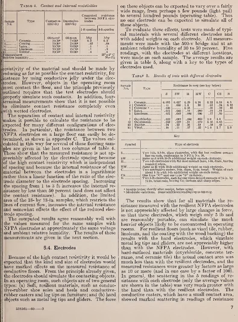
Table 4. Contact and internal resistivities
SampleNo.
Typo Contact re-
sistivity
Internal re-
sistivity
Computed resistancebetween NFPA elec-
trodes
1-ft spacing 3-ft spacing
1 Ceramic —Ohm-cm2
3XW3X105
2X1062X10«2X16«
Ohm-cm7X10'2X10³
9X1032XW9X101
Meg0.2.03.1. 1
.4
Meg0.2.04. 1
.2
.4
3 Coating5 Latex. .
6 Linoleum.13 Rubber... .
Relative humidity. 50±5%
resistivity of the material and should be made byreducing as far as possible the contact resistivity, for
instance by using conductive jelly under the elec-
trodes. However, objects in the operating roommust contact the floor, and the principle previously
outlined requires that the test electrodes shouldproperly simulate such contacts. In addition, four-
terminal measurements show that it is not possible
to eliminate contact resistance completely evenwith wetted electrodes.
The separation of contact and internal resistivity
makes it possible to calculate the resistance to beexpected for many different configurations of elec-
trodes. In particular, the resistance between twoNFPA electrodes on a large floor can easily be de-
termined, as shown in appendix C. The values cal-
culated in this way for several of these flooring sam-ples are given in the last two columns of table 4.
These show that the measured resistance is not ap-
preciably affected by the electrode spacing becauseof the high contact resistivity which is independentof spacing and because the internal resistance of the
material between the electrodes is a logarithmic
rather than a linear function of the ratio of the elec-
trode diameter to the electrode spacing. Increasing
the spacing from 1 to 3 ft increases the internal re-
sistance by less than 50 percent (and does not affect
the contact resistance). In addition, the limited
area of the 18- by 18-in. samples, which restricts the
lines of current flow, increases the internal resistance
and somewhat offsets the effect of the reduced elec-
trode spacing.
The computed results agree reasonably well withthe values measured for the same samples withNFPA electrodes at approximately the same voltage
and ambient relative humidity. The results of these
measurements are given in the next section.
5.4. Electrodes
Because of the high contact resistivity it would beexpected that the kind and size of electrodes wouldhave marked effects on the measured resistance of
conductive floors. From the principle already given,
the electrodes should simulate the contacting objects.
In an operating room, such objects are of two general
types: (a) Soft, resilient materials, such as conduc-tive-rubber shoe soles and heels and conductive-rubber casters and leg tips on furniture; and (b) hardobjects such as metal leg tips and gliders. The force
538361—60 2
on these objects can be expected to vary over a fairly
wide range, from perhaps a few pounds (light pail)
to several hundred pounds (operating table). Thusno one electrode can be expected to simulate all of
these objects.
To evaluate these effects, tests were made of typi-
cal materials with several different electrodes andwith added weights on each electrode. All measure-ments were made with the 500-v bridge and at anambient relative humidity of 30 to 50 percent. Fivereadings, with the electrodes at different locations,
were made on each sample. The average results are
given in table 5, along with a key to the types of
electrodes used.
Table 5. Results of tests with different electrodes
SampleNo. Type
CeramicCeramicConcrete a .
.
LatexLinoleum .
.
OxychlorideOxychlorideRubberVinyl
Resistance in meg (see key below)
0. 055. 11
.026
.051
.051
.022
.023
.24
.16
SW
0.037.060
.040
.049
.019
.019
.23
. 11
H
0.291.4
0.28.16.080
.080
. 11
.36
.37
HW
0. 24
.80
.060
.070
.33
.22
0. 33.65.30.22.17
2.00. 25.53
b 1. 0
CS B
0. 14.34.38. 11
.10
1.00. 65.41
1.7
6.50. 85.85
1.0
Key
Symbol Type of electrode
S Two 5-lb, 2.5-in. diam electrodes, with flat but resilient contactface on each, conforming to NFPA No. 56.
Same as S with 50-lb additional weight on each electrode.
Two 5-lb electrodes with flat steel contact faces, 1-in. diam, havingrounded edges.
Same as H with 50-lb additional weight on each electrode.
Two conductive casters, 3-in. diam, H-in. tread. Weight of eachabout 1 lb with 5-lb additional weight on each caster.
One type "C" and one type "S" electrode.
Two 5-lb electrodes, each having three-legged contacts of J-s-in. by}&-m. brass rods, having flat surfaces and sharp edges.
SWH
HWC
CSB -
» Sample tested shortly after receipt, before aging.b Moderate variations. Some additional readings up to 100 meg.
The results show that for all materials the re-
sistance measured with the resilient NFPA electrodes
is not appreciably affected by large changes in force,
so that these electrodes, which weigh only 5 lb andare reasonably portable, can simulate the muchheavier objects likely to be encountered in operating
rooms. For resilient floors (such as vinyl tile, rubber,
linoleum, and the coating with the wood backing) the
results with the hard electrodes, which simulate
metal leg tips and gliders, are not appreciably higher
than with the NFPA electrodes. However, withhard-surfaced materials (oxychloride, concrete ter-
razzo, and ceramic tile) the actual contact area wasmuch less than with the resilient electrodes, and the
measured resistances were greater by factors as large
as 10 or more (and in one case by a factor of 100).
In general, the scattering in the 5 readings of re-
sistance with each electrode (only the average values
are shown in the table) was very much greater withthe hard than with the resilient electrodes. Theconductive casters, which have a small contact area,
showed marked scattering in readings of resistance

on some samples. The differences between results
with two standard electrodes and those with twocasters were less marked for resilient flooring (exceptfor vinyl tile) than for hard-surfaced materials.
(Field tests of a conductive vinyl tile floor of thesame manufacture gave nearly equal results withcasters and standard electrodes.) The special 3-
legged electrodes have been suggested for simulatinghigh-pressure contacts. The resistances were in
general comparable with or somewhat higher thanthose with the 1-in. hard electrodes.
Thus the resilient electrodes simulate well onetype of floor contact and give much more uniformand reproducible results than hard-surfaced elec-
trodes. However, when such resilient electrodes
are specified, the upper limit of resistance for aninstalled floor must contain a large factor of safety
to allow for hard-surfaced objects which are also
widely used. This factor depends upon the resiliency
of the floor, so that apparently the specified upperlimit with a resilient floor such as conductive rubberor linoleum could safely be 10 times as high, whenmeasured with these electrodes, than the limit for
a hard floor such as oxychloride or concrete terrazzo.
5.5. Frequency
The lower limit of resistance specified in NFPANo. 56 for conductive floors is intended to providesome (but not complete) protection from electric
shock. Alternating current (120 v, 60 cps) is almostuniversally used in this country for electrical utiliza-
tion circuits. Because of this it would appear thatthe resistance of the floor should be measured atthis voltage and frequency to determine compliancewith the lower limit. For convenience, however,the same d-c instrument is normally used for bothupper and lower limit tests. The instrument com-monly specified has an open circuit voltage of 500 v.
However, the actual voltage that it impresses on thefloor under test depends upon the resistance of thefloor and the internal resistance of the instrument,as shown in figure 6. From this figure it is apparentthat a 500-v instrument having an internal resistance
of almost 0.1 meg will impress about 100 v on asample near the NFPA lower limit of 25,000 ohms(0.025 meg).Measurements of several flooring samples were
made at 100 v, with alternating and direct current,
and with a typical 500-v ohmmeter which has aninternal resistance of 0.1 meg. All measurementswere made with the standard resilient electrodes at
the same location on each sample, and at an ambientrelative humidity of about 40 percent. The results
given in table 6 show no really significant differ-
ences between the a-c and d-c measurements of agiven sample at 100 v. They also show that for
samples near the lower limit of 0.025 meg the ohm-meter value agreed reasonably well with others.
For samples of higher resistances the ohmmeterimpressed more than 100 v on the sample and themeasured resistance was, in general, less, as wouldbe expected from the observation that resistance is
an inverse function of the voltage, as shown in sec-
Table 6. Ac-dc comparison tests
SampleNo. Type
CeramicCeramicConcreteLatexLinoleum, „
OxychlorideOxychlorideOxychlorideRubberVinyl
Resistance in meg
At 100 V At 100 v60 cps, ac dc
0. 20 0. 23.31 .34.009 .024.21 .25.055 .057
.042 .038
.012 .007
.063 .040
.21 .23
.60 .78
WithI
ohmmeter
,
0. 0751
.10,
.01?
.07?
.050I
. 03C,
.oiq
.04C
.21
.20,
tion 5.1. The 500-v instrument specified in NFPANo. 56 (internal resistance 50,000 to 200,000 ohms)!thus can be expected to give results which are
reasonably close to those obtained with the some-what more complex instruments required for a-c;
measurements, and make it unnecessary to specify
two different instruments for measuring installed
floors. However, as figure 6 shows, the range ol
internal resistance specified in NFPA No. 56 couldbe greatly narrowed. A short circuit current of
5 ±0.5 ma corresponding to a nominal interna'
resistance of 100,000 ohms is suggested.
10,000 100,000 I MEG. 10 MEG.(
MEASURED RESISTANCE , OHMS
Figure 6. Output voltage of ohmmeters as a function of measured]resistance.
I
Characteristics of ohmmeters shown in block on graph.
5.6. Instruments
A number of different instruments are commer- 1
cially available for measuring the resistance of con-
ductive floors. Instruments fall into three general
classes: (a) Simple ohmmeters; (b) ratio ohmmeters;and (c) Wheatstone bridges [6].
A simple d-c ohmmeter consists of a battery,
milliammeter, and a resistor, R, all in series with the
unknown resistor, X, to be measured. The currenti
through the milliammeter is adjusted (by shunting
the milliammeter or adjusting R) 6 to give full scale
deflection of the instrument, which is marked zero
on the scale. The current through the instrument
is then a function of X and the scale is marked
s The internal resistance can usually be computed as the quotient of the opencircuit voltage divided by the short circuit current of the instrument.
8 It is much more desirable to shunt the milliammeter, since the calibration
depends on R.
8

I
1 accordingly. Such ohmmeters with 1.5- or 3-vbatteries are commonly used in radio or television
service instruments. As indicated in section 5.1,
these voltages are far too low for meaningful tests
of conductive flooring. However, at least one: manufacturer has incorporated a vibrator-trans-
j
former power supply operated from a dry cell to
produce a 500-v conductive-flooring tester.
The moving element in a ratio-type ohmmetercontains a permanent magnet and two rotatable
coils fixed at right angles to each other, one of whichfunctions as in the simple ohmmeter while the othercarries a current proportional to the applied voltage.
With no springs, the coils then take up a position
which is a function of the ratio of the voltage to thecurrent, and the scale is laid off in ohms or megohms.The reading is then desirably independent of the
voltage, and a zero setting is not necessary. Mostratio ohmmeters also contain handcranked generators
to produce the desired voltage.
Wheatstone bridges with electronic detectors havebeen used occasionally, but are best suited for
laboratory work, since a balance must be madebefore each reading. They are generally capableof greater accuracy and flexibility than ohmmeters.
Table 7 shows the general characteristics of com-mercially available instruments which are suitable
for testing conductive flooring. In accordance withNFPA No. 56, such instruments must have an opencircuit voltage of 500 v, a short circuit current of 2.5
to 10 ma, and should have a range of at least 0.01 to
2 meg. Unfortunately, many models of 500-vinsulation testers have a higher internal resistance
and resistance range than this. Only moderateaccuracy is required in field tests of conductiveflooring because of the large variations inherent in
most materials. An accuracy of 20 percent of the
measured resistance in the range 0.025 to 1 meg-should be adequate. It can be shown that, becausethe scale of an ohmmeter is necessarily nonlinear,
the markings on the scale must then be accurate to
2 percent of the full-scale length, and the resistors and
Table 7. Characteristics of typical instruments for measuringresistance of conductive floors
Range » Ap-Open- Short- Inter- proxi-
Type Energy circuit circuit nal re- matesource voltage current sistance mid-
Low High scalereading
ma meg meg meg megRatio ohm- Hand- 0-500 3.5 0. 14 0.005 10 0.20meter. cranked.
Ratio ohm- Hand- 0-500 10 .05 .010 50 .80meter. cranked.
Simple ohm- Internal, 500 3 . 17 .010 10 .18
meter. battery.Simple ohm- Internal 500 2.5 .20 .010 10 .23meter. battery.
Ratio ohm- Hand- 500 5 .10 .010 50 .50meter. cranked.
Megohm 110 v a-c 500 10 b.001 <>100
bridge.
» Lowest and highest markings on scale exclusive of zero and "infinity"markings.
b At listed short-eireuit current; additional ranges to 1,000,000 meg at lowercurrents.
other component parts must be accurate to betterthan 10 percent.
The data on the modified megohm bridge areincluded for reference. The instrument was foundto be accurate to 1 percent and well suited for
laboratory studies because of its wide voltage andresistance ranges. However, it would not be as
convenient as the others for routine tests of installed
floors.
6. Electrostatic Tests
The electrical tests of conductive flooring samplesoutlined in sections 4 and 5 have been made underdeliberately varied conditions, such as relative
humidity and applied voltage, to determine theeffect of ambient conditions and of normal use uponthe samples, and to evaluate the factors which maybe expected to influence the measurements. Tosubstantiate these results, additional experimentswere carried out in which each type of floor wasactually used as an intercoupler to reunite electro-
static charges. These experiments provided a direct
test of the effectiveness of each type of floor in
eliminating hazards from static electricity.
Tests in the NBS laboratories have shown that a
person rising from a plastic-covered chair whilewearing wool clothing causes a separation of chargesat as high a time rate (and therefore charging cur-
rent) as any human action tested. A comparativelylow resistance is thus required to keep the voltagebetween the objects concerned (chair and personrising from it) below the minimum sparking voltage,
about 400 v in air at normal pressure. If the voltageis less than this, true electrostatic sparks do notoccur [2]. This experiment therefore provides agood test of the actual performance of a floor, if the
peak voltage between the objects can be measured.A few measurements of the voltages produced in
such tests have been made in the NBS laboratories
by using a high-resistance voltage divider, cathoderay oscillograph, and camera. 7 However, this provedto be too cumbersome for the many tests requiredfor these floors, so that a simple peak-voltage in-
dicator was constructed. It consisted of four small
sensitive neon lamps (NE2 or equivalent) connectedin series with a 40 pf capacitor across each. Thelamps and capacitors were mounted in a small
blackened metal tube having a lens at one end.
The capacitors assure that equal transient (or
alternating) voltages appear across each lamp until
one lamp fires (glows), after which all glow. Testsshowed that the firing voltage was about 300 v,
somewhat less than the minimum sparking voltage.
The "dark" resistance at lower voltages ranged from5,000 to more than 20,000 meg. Additional tests
were made later of some samples, with two neonlamps added to the indicator, so that the firing
voltage was about 450 v, approximately that of the
standard instrument for measuring floors (500 v)
.
For these tests a person wearing conductive shoes
held the peak-voltage indicator. The other terminal
7 Since this is a transient voltage an ordinary electrostatic voltmeter can notbe used.
9

of the indicator was connected to the frame of ametal chair (having flat metal gliders % in. diam)which rested on the flooring sample. 8 The personsat in the chair, and then, while observing the indica-
tor, rose from the chair (with a forward sliding
motion) with his feet on the same sample and notedwhether or not the lamps glowed. At least five suchtrials were made with each flooring sample. Theresistance of the sample between two standardelectrodes and between the metal frame of the chair
and the subject was measured immediately after
each test at three or five different locations on thesample.
Additional tests were made on an insulating floor
with a resistor connected between the chair and thesubject. The tests were repeated with resistors of
successively lower value until the lamps glowedwhile the person rose from the chair. These tests
thus determine the actual safe upper limit resistance
for the motion and materials involved.
All of the tests with the flooring samples and theresistors were made at an ambient relative humidityof 20 percent, with a plastic covered chair and asubject who wore a wool suit, conditions which are
very favorable to the generation of static electricity.
The results of these tests are given in table 8.
The last three rows of the table show that the actualsafe limiting resistance to keep the voltage betweenthe chair and subject below the minimum sparkingvoltage (400 v) for the motion and materials usedwas about 30 megs. A resistance less than 20 to 30megs was required to keep the voltage below 300 v,
the firing voltage of the 4-lamp indicator.
The range of measured resistances between thechair and subject are given in the fourth column of
the table. As indicated in section 5.4 this range is
much greater with hard surfaced electrodes such as
the leg tips on this chair than with resilient elec-
trodes. (This is one reason why the resilient elec-
trodes are preferred for routine tests.) The results
show that except for sample No. 5 the peak voltagewas less than 300 v when the measured resistance
between the chair and subject was less than about30 meg, and vice versa. 9 Thus there is excellent
correlation between the resistance of a conductivefloor as measured with a standard 500-v d-c instru-
ment, and the resistance to the flow of electrostatic
charges through the same electrodes (contactingobjects).
The upper limit of resistance specified for a con-ductive floor with the standard electrode is 1 meg.The results show that, for all samples except Nos. 5and 11, the peak voltage is less than 300 v, if theresistance between the two standard electrodes is
less than 1 meg, and vice versa. Thus the specified
1-meg limit with two standard electrodes is a reason-
! Because of the small size of the sample only the front legs of the chair restedon the sample. Insulators were placed under the rear legs. For some of the testswith the 4S0-V indicator, two flooring samples of the same type were connectedtogether so that all four legs of the chair rested on the conductive floor.
• Additional tests showed that the manufacturer of sample No. 5 had applieda sealer which sometimes effectively insulated the hard-surface gliders of thechair, but not the standard electrodes. With hard electrodes the breakdownvoltage of this insulating film ranged from 100 to more than 400 v. This sealer is
no longer applied on conductive floors by the manufacturer of this sample.
Table 8. Results of electrostatic tests
Ambient temperature 25° C; relative humidity 20%; plastic chair covering; wool i
garment (see text)
SampleNo. Type
Resistance (megs) between: Peak voltagegreater than: <
Twostandardelectrodes(average)
Chair and subject(min. & max.)
300 v 450 v
24
S
67
89
10
11
12
13
15
Ceramic. _ 0.2.9.05. 03
6
2301.50.3.6
.1
.2
0.3 to 0.5 NoConcrete.Latex..Linoleum... ..
3 to 300 08 to 0 09
YesYes.No
No.Yes.
Oxychloride 140 to 260 Yes
Oxychloride.Oxychloride.. _
15 to 45200 to 400
Yes...Yes
No.
Oxychloride _.
Oxychloride. .
Oxychloride .. _.
7 to 651 to 502 to 5
Yes...Yes...
No.Yes.No.
Rubber 0.08 to 0.18 NoVinyl .3 to 0.4 NoResistor 20 meg NoResistor 30 meg Yes...
Yes...No.Yes.Resistor 50 meg
« "Yes" signifies that the designated peak voltage was exceeded at least oncein five or more trials.
ably valid criterion of the performance of thesefloors.
These tests therefore show that the actual resist-i
ance between the objects on which the charges are I
generated (or transferred by induction) is theimportant criterion of the effectiveness of a conduc-tive floor as an electrostatic intercoupler, and that I
this can be measured reasonably well with thespecified 500-v instrument. In case of doubt, as for
example floors which are slightly above the 1-meg l
limit with the standard electrodes, measurements of 1
the resistance between objects in the room can!
provide additional evidence of the safety of thej
floor (and the contacting objects) with respect to|
the hazards from static electricity.
These tests indicate that for resilient floors thereis an appreciable "factor of safety" (about 10) for
the present 1-meg specification, even at this very-low relative humidity, because the resistance of such i
floors is relatively independent of the hardness of|
the contacting objects. There would appear to bej
no such factor for hard-surfaced floors. However,additional tests indicate that there is a very large
'
factor of safety (10 or more) if, as specified in NFPANo. 56, materials such as wool and plastics are
|
prohibited. Such materials are excellent electro- i
static generators because of their very high elec-
trical resistivities. In addition, because the resist-\
ance of many insulating materials depends upon thej
ambient relative humidity, there is another very :
large factor of safety if, as recently specified in
NFPA No. 56, a relative humidity of 50 to 60 percenti
is maintained.|
7. Nonelectrical Properties
7.1. Indentation
Indentation studies included the determination of
initial indentation under load and residual indenta-
10

tion after removal of the load. The initial indenta-tion is sometimes referred to as the "comfort value",in that it expresses the ability of a floor to depressreadily under foot. The value of the residual inden-tation, on the other hand, is an indication of theresistance to permanent deformation due to a con-centrated load, such as a table leg. The ideal floor
might thus be considered as one which has a highinitial indentation or "give" and a low residual in-
dentation or high recovery. In table 9, linoleum,rubber, and vinyl show a much higher initial inden-tation than the ceramic, concrete, and oxychloridematerials. However, other important factors are in-
volved in determining comfort value which are of anindirect nature, but which can be of major impor-tance, e.g., the type of footwear involved. Compar-ison of these results with those reported in BMS-73[7] show that the indentation characteristics of theconductive materials are comparable to those of thecorresponding nonconductive materials.
Table 9. Indentation characteristics
Sam-pleNo.
Type Thick-ness
Initial indentation Residual indentation
A B c
1 hr after removalol load
48 hrafter
removalof load
A B c c
1
2345
6789
10
11
12
131415
Ceramicin.
0. 25.25.035.50.443
.134
.50
.50
.56
.50
.50
.50
. 126
.121
.193
in.
0. 000.000.011
.000
.009
.024
.000
.000
.000
.000
.000
.002
.029
.043
.047
in.
0.000.000.007.000.007
.005
.000
.000
.000
.000
.000
.000
.008
.021
.011
in.
0.000.000.009.000.014
.007
.000
.000
.000
.000
.000
.000
.006
.024
.017
in. in. in. in.
doCoatingConcrete
0. 003 0. 000 0. 000
Latex. .002
.003
.000
.000
.000
.002LinoleumOxychloride
dododo
dodo
RubberVinyl— .do
0.001
.000
.002
.006
.002
.000
.007
.002
.001
.007
.009
.000
.000
.006
A=80-lb load applied 10 min through a 0.178-in.-diam indenter foot (3,200lb/in.2).
B=100-lb load applied 10 min through a 1.125-in.-diam indenter foot (100lb/in.2).
C= 100-lb load applied 7 days through a 1.125-in.-diam indenter foot (100lb/in.2).
In the case of sample No. 3 (coating), the results
reflected predominantly the indentation characteris-
tics of the plywood backing because of the thinness
of the coating material. The result would undoubt-edly have been different if the same material hadbeen applied over concrete.
The indentation tester and procedure used in mak-ing the indentation and recovery determinations are
described in detail in Report BMS-73 [7] and in
Federal Specification LLL-L—367 for Linoleum.
7.2. Scratch Resistance
Precise measurements of scratch resistance, as de-scribed in the paragraph below, were made on eachsample. This value relates to the ease with which
the floor surface can be scuffed and marred by abra-sive material carried on shoes. Resistance of con-ductive flooring materials to surface scratching is ofprime importance in operating rooms for the sake ofcleanliness as well as the possible effect on electrical
contact resistance. In order to establish a basis bywhich these values can be related to actual service,
each sample was placed on the pedestrian traffic test
ramp described later.
The Taber Scratch Tester was adapted to measurethe scratch width of a diamond point at loads of
250, 500, 750, and 1,000 g. A level plate capable of
travel at a uniform rate of 1 ft/min was used in
moving the flooring sample under the diamond-point scratch tool. A scratch 2 in. long was madeand the width of the scratch was measured at threelocations with a 20X Brinell microscope containinga scale graduated in 0.1 mm. The average of thethree measurements was converted to the nearest0.001 in. and recorded as scratch width in mils.
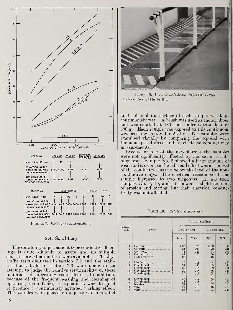
The graph, figure 7, illustrates the results.
A pedestrian traffic test ramp was constructed(see fig. 8). Each flooring sample was securelyplaced on the test ramp and a photoelectric counterwas installed to count passages over the ramp. Thelength of the entrance at each end of the test rampwas altered every 3 months, causing a change in thefoot traffic pattern and therefore insuring that eachsample received the same amount of wear. Theramp was located on the third floor of the Industrial
Building, NBS, away from street grit, gravel, andwater, but exposed to light industrial-type dirt anddust. No attempt was made to maintain the samplesother than an occasional dry sweeping. These con-ditions were considered more severe than in hospital
operating rooms, resulting in an accelerated test.
Photographs taken after 11 months of wear (100,000passages) were compared with photographs of
unexposed flooring to determine the extent of
scratching, smudging, and other damage (see fig. 9).
A comparison chart of visual appearance of the
scratching on the exposed samples is listed belowthe graph in figure 7.
7.3. Slippeiiness
Tests of relative slipperiness of the conductiveflooring samples were made with leather and rubberheels under both wet and dry conditions. Themethod of testing and a description of the instrumentused have been previously reported [8]. Slipperiness
is not a constant of the walkway surface or of the
contact surface of the footwear alone, but is a func-
tion of both surfaces and is materially affected bytheir conditions. Therefore, an unqualified evalua-
tion of a particular floor or floor finish may be verymisleading.
The results in table 10 show the antislip coeffi-
cients; the higher the value, the less slippery the
surface. Comparison of these results show that
the antislip characteristics of the conductive mate-rials are comparable to those of the corresponding
nonconductive materials.
11
2 —i a 2
0 250 500 750 1000LOAD ON DIAMOND POINT, GRAMS
MATERIAL CERAMIC COATINGCONCRETE , IMnl ...„TERRAZZO LINOLEUM
NBS SAMPLE NO. 1 2 3 4 6
CONDITION AFTER3 MONTHS SERVICE
(33,000 PASSAGES)GOOD
1
GOOD1
FAIR1 1
GOOD POOR
CONDITION AFTERII MONTHS SERVICE(100,000 PASSAGES)
GOOD GOOD FAIR GOOD POOR
MATERIAL OXYCHLORIDE RUBBER VINYL
NBS SAMPLE NO. 7 9 10 II 12 13 14 15
CONDITION AFTER3 MONTHS SERVICE
(33,000 PASSAGES)
1
GOOD1
FAIR1 1
GOOD GOOD1 1 1
POOR POOR FAIR1
FAIR
CONDITION AFTERII MONTHS SERVICE(100,000 PASSAGES)
FAIR FAIR GOOD GOOD POOR POOR FAIR FAIR
Figtjbe 7. Resistance to scratching.
7.4. Scrubbing
The durability of permanent type conductive floor-
ings is quite difficult to assess and no suitable
short-term evaluation tests were available. The dry-traffic tests discussed in section 7.2 and the stain-
resistance tests in section 7.6 were made in anattempt to judge the relative serviceability of thesematerials for operating room floors. In addition,
because of the frequent washing and cleaning of
operating room floors, an apparatus was designedto produce a continuously agitated washing effect.
The samples were placed on a plate which rotated
Figure 8. View of pedestrian traffic test ramp.
Each sample was 18 in. by 18 in.
at 4 rph and the surface of each sample was keptcontinuously wet. A brush was used as the scrubber i
and was rotated at 180 rpm under a total load of I
500 g. Each sample was exposed to this continuous
'
wet-brushing action for 52 hr. The samples were I
examined visually by comparing the exposed withj
the nonexposed areas and by electrical conductivitymeasurements.Except for one of the oxychlorides the samples
were not significantly affected by this severe scrub- 1
bing test. Sample No. 8 showed a large amount of i
wear and erosion, so that the end effect was a removal i
of the conductive matrix below the level of the non-conductive chips. The electrical resistance of this
sample increased to two megohms. In addition,
samples No. 9, 10, and 11 showed a slight amountof erosion and pitting, but their electrical conduc-tivity was not affected.
Table 10. Relative slipperiness
SampleNo. Type
Antislip coefficient
Leather heel Rubber heel
Dry Wet Dry Wet
1 Ceramic 0. 37 0.26 0. 68 0.44
K2J Ceramic . _ . .34 .26 .72 .313 Coating.. _ . .33 .26 .74 .464 Concrete terrazzo _ .43 .26 .56 .305 Latex terrazzo .32 .10 .73 .13
6 Linoleum .37 .18 .68 .377 Oxychloride..- .39 .38 .68 .488 Oxychloride - .36 . 15 .62 .21
9 Oxychloride .21 .18 .58 .2410 Oxychloride .37 .14 .58 .22
11 Oxychloride . . .. .37 .12 .55 . 16
12 Oxychloride .34 .13 .54 .3913 Rubber . . .39 .12 .67 .1314 Vinyl .26 .16 .46 . 10
15 Vinyl .28 .13 .63 .23
12

til h . / i,X ^"•>"'
v
Figure 9. Photographs of four samples from the pedestrian traffic test ramp which were appreciably affected by the test.
A, Sample No. 8 (oxychloride), showing hairline cracks; B, Sample No. 2 (ceramic), showing pitting in mortar joints; C, Sample No. 13 (rubber), showing extremescuffing and scratching. No wax was used; D, Sample No. 15 (vinyl), showing extreme soiling of light colored tiles.
ribbon which connects the tiles electrically.
One tile has been removed to show the copper
7.5. Water Absorption
It has been considered desirable that a flooring
material designated for an area subject to frequentwashing should have a very low rate of water ab-sorption in order to reduce staining, leaching, anderosion by water and detergents. To establish therates of water absorption the following test wasperformed on each sample:
One-tenth milliliter of water was placed on thesample with a pipet and covered with a watch glass.
The number of minutes required for complete absorp-tion of the 0.1 ml of water was taken as the time of
absorption. Complete absorption was assumed to
have taken place when light no longer was reflected
from the wetted surface of the sample. All theflooring materials except the five listed below re-
quired more than 5 hr for the water to disappear andcan therefore be considered fairly irnpervious to
water.
No. Type Time of absorp-tion
min4 Concrete terrazzo . 158 Oxychloride 49 Oxychloride 6
10 Oxychloride. 611 Oxychloride. 22
7.6. Stain Resistance
A high resistance to staining (or ease of cleaning
when stained) is a desirable characteristic of aflooring material intended for use in an area wherethere is likely to be spillage. Table 11 lists recom-mended methods for removing certain stains. Careshould be used in applying the solutions. Forexample, acid solutions are usually the most effective
means of removing rust stains from concrete; 10
percent solutions of hydrochloric or phosphoric acid
are commonly used. Acids should not, however,be allowed to remain in contact with the surface
any longer than is necessary to remove the stains.
With any such treatment, some roughening of the
concrete is inevitable and may be conspicuous. Asa precaution it is advisable to carry out a trial on a
small area to determine if the resulting appearanceis acceptable. Table 12 gives results of tests
carried out to determine the effect on the conductivefloor samples of various staining agents and the ease
or difficulty with which the stains were removed.
8. Summary and Conclusions
1. The conductive floors tested should give satis-
factory service in hospital operating suites, with the
reservations outlined below. Similar conclusions canbe drawn from the results of extensive tests by the
staff of the National Research Council of Canada of
several types of installed floors [9]
.
13

Table 11. Stain-removal methods
Stain Linoleum Ceramic Concrete terrazzo Latex terrazzo Oxychloride Vinyl Coating Rubber
Blood
Grease or oil.
Apply cool water and rub with cloth. It stain persists, dampen cloth with ammonia.
Apply detergentand rub withcloth.
Apply detergent and rub with cloth. If stain persists apply kerosene orvarsol on spot, permit to soak, wipe dry and wash with detergent, or mixkerosene or varsol with fuller's earth to form paste. Apply paste to spotand let stand for several hours. Repeat if necessary.
Apply detergent and rub with cloth.
Ink (washable,writing, anddrawing)
.
Paint or enamel
Iodine
Rust
Apply detergent and rub with cloth. If stain persists, mix 1 part sodium perborate to 25 parts water. Mix with whiting (calcium carbonate^to form paste. Apply paste to spot and leave until dry.
Remove excess with putty knife and/or No. 0 steel wool. Apply kerosene, turpentine, or varsol. "Wash withdetergent.
Remove with putty knifeand No. 0 steel wool.
Apply alcohol and rub with cloth
J v,
Apply alcohol and cover with fuller's earth.
Rub with No. 0steel wool andwash with de-tergent.
Apply water and rub with cloth. If stain persists
apply solution of 1 part oxalic acid to 9 parts water.Let remain until dry. Wash thoroughly withwater.
Apply water andrub with cloth.
If stain persists,
dissolve 1 partsodium citrate in6 parts water.Make a pastewith whiting (cal-
cium carbonate)and apply tostain, or washwith sodium ci-
trate solution andadd pad of cottonsoaked in sodiumbisulfite. Washthoroughly withwater.
Same as for linoleum.
Same as for linoleum.
-
's
Sole and heePmark-ing.
Apply detergent and rub with cloth.
Table 12. Results on removal of stains
SampleNo.
Type Blood Greaseor oil
InkPaint
enamelIodine Rust
Soleandheelmarks
1 Ceramic a B B B B B B A2 Ceramic a B B B B B B A3 Coating B B B B B B B4 Concrete ter-
razzo _ B C C B B C B5 Latex terrazzo
with sealer. __ B B B B B B BLatex terrazzowithout sealer B B C B F C B
6 Linoleum _ B B B B B B A7&8 Oxychloride D B D B B F B9 Oxychloride ... F F F B B B B10 Oxychloride ... B F D B A F B11 Oxychloride B B D B F B A
12 Oxychloride ... D F D B B B B13 Rubber B B B B B C B14 Vinyl B B B B C B C15 Vinyl _. B B C B C B C
Note: A, Staining material would not stain or mark floor; B, stain completelyremoved with little effort; C, stain completely removed, but with difficulty:
D, stain completely removed, but floor surface bleached or etched; F, stain notremoved.
* Results on cement joints same as No. 4, concrete terrazzo.
2. In general, any particular type of conductiveflooring may be expected to render service com-parable to nonconductive flooring of the same type.
Consequently, an architect may base his choice of
a conductive flooring material on his knowledge of
the behavior of similar nonconductive materials,
with the following limitations
:
(a) The durability and appearance of at least
two of the available materials (linoleum and rubber)
may depend on periodic waxing. Conductive waxescontaining carbon black which do not deposit aninsulating film are available and should be estheti
cally as well as electrically satisfactory on these uni
formly black floors. Sealers should not be used onconductive floors until proven satisfactory by ex-
tensive electrical tests.
(b) Since the most commonly used conductive
medium (acetylene black) is black, the colors avail-
able in most types of conductive floors are limited
However, terrazzo and other pattern effects can be'
used. Detailed descriptions of some of the avail-
able colors and patterns are given in section 3.
(c) The electrical resistance of the oxychloride
floors depended on their moisture content, which in|
turn was governed by the humidity of the air and'
by water added during washing. The results or
the tests given in this report indicate that if this,
material is used the relative humidity of the ah in
the room in which it is installed should be controlled
and the cleaning schedule for the floor should becarefully established and maintained. The labora-|
tory tests indicate that otherwise the electrical re-
sistance of the floor may fall outside the accepted'
limits.
3. The results of this investigation indicate that!
the presently accepted method of measuring the
resistance of installed floors, described in NFPANo. 56, reasonably simulates the conditions unde^which a floor is expected to function as an electro-
static intercoupler.
14

f 4. The results also show that current specifications
jhnd methods of measuring the physical properties
jpf nonconductive floorings are satisfactory for con-ductive floorings.
The work described in this report was done under! a, project sponsored jointly by the Office of the Chief
of Engineers, Department of the Army; Bureau of
'iYards and Docks, Department of the Navy; and'Engineering Division, Director of Civil Engineering,^Department of the Air Force.
The authors appreciate the cooperation of the
[staff of the Division of Building Research of the
National Research Council of Canada, particularly
Mr. P. J. Sereda, in making available their experience
with conductive flooring. The cooperation of the
numerous manufacturers who generously providedsamples is also acknowledged.
9. References
[1] P. G. Guest, V. W. Sikora, and B. Lewis, Static elec-
tricity ir hospital operating suites: Direct and related
hazards and pertinent remedies, Bureau of MinesReport of Investigation 4833, 64 pp. (1952).
[2] F. B. Silsbee, Static electricity, NBS Circ. 438 (June1942).
[3] F. L. Hermach, Hazards from static electricity, TheMilitary Engineer 44, 287 (1952).
[4] Recommended safe practice for hospital operating rooms,N.F.P.A. No. 56, National Fire Protection Association(reproduced in part in appendix A of this report).
[5] Robin Beach, Electrostatic safety for hospital operatingrooms, Elec. Eng. 72, 329 (April 1953).
[6] AIEE master test code for resistance measurements,Publication No. 550, Am. Inst. Elec. Engrs., NewYork, N.Y.
[7] Percy A. Sigler and Myrtle B. Woodward, Indentation of
floor coverings, NBS BMS Report 73, 7 pp. (1941).
[8] Percy A. Sigler, Martin N. Geib, and Thomas H. Boone,Measurement of the slipperiness of walkway surfaces,
J. Research NBS 40, 339 (May 1948) RP1879.[9] P. J. Sereda, Properties of commercial conductive flooring
for hospital operating rooms, Division of BuildingResearch, Nat. Research Council Can., NRC 4031.
10. Appendix A. Excerpts 10 from the 1958Edition of NFPA Publication No. 56,
Recommended Safe Practice for
Hospital Operating Rooms6-2. Conductive Flooring.
(a) Resistance.
1. To prevent the accumulation of dangerouselectrostatic charges, the surface of the floor . . .
shall provide a path of moderate electrical conduc-tivity between all persons and equipment makingcontact with the floor. No point on a non-con-ductive element in the surface of the floor shall bemore than % inch from a conductive element of the
surface.
NOTE: It is not necessary to provide a special
floor-to-ground connection unless required bythe authority having jurisdiction.
2. The resistance of the conductive floor shall be
io Reproduced by permission of the National Fire Protection Association, 60
Batterymarch Street, Boston, Massachusetts.
less than 1,000,000 ohms as measured between twoelectrodes placed three feet apart at any points onthe floor.
3. For additional protection against electric shock,the resistance of the floor shall be more than 25,000ohms, as measured between a ground connectionand an electrode placed at any point on the floor,
and also as measured between two electrodes placed3 feet apart at any points on the floor.
(b) Method of Test.
1. The floor shall be clean and dry and the roomshall be free of explosive gas mixtures. Each elec-
trode shall weigh 5 pounds and shall have a dry, flat,
circular contact area 2)i inches in diameter whichshall comprise a surface of aluminum or tin foil
0.0005 to 0.001 inch thick backed by a layer of
rubber }{ inch thick and measuring 50 plus or minus10 hardness as determined with a Shore Type Adurometer. (American Society for Testing Mate-rials Tentative Method of Test for Indentation of
Rubber by Means of a Durometer, ASTM Desig-nation D676^9T, obtainable from ASTM, 1916Race St., Philadelphia 3, Pa.)
2. A suitably calibrated ohmmeter with a nominalopen-circuit output voltage of 500 volts D.C. anda short-circuit current of 2.5 to 10 milliamperesshall be used. Measurements* shall be made at
five or more locations in each room and the results
averaged. For compliance with Section 6-2 (a) 2,
the average shall be within the limits specified andno value shall be greater than 5 megohms. Forcompliance with Section 6-2 (a) 3, no location shall
have a resistance of less than 10,000 ohms and the
average for not less than five locations shall begreater than 25,000 ohms. Where resistance to
ground is measured, two measurements shall bemade at each location, with the test leads inter-
changed at the instrument between measurements,with the average to be taken as the resistance to
ground at that location. All readings may be takenwith the electrode or electrodes more than 3 ft.
from any ground connection or grounded object
resting on the floor.
*NOTE: If the resistance changes appreciably
with time during a measurement, the valueobserved after the voltage has been applied for
about 5 seconds shall be considered to be the
measured value.
13-10. Testing and Maintenance
(a) Conductive Floors
1. The resistance of conductive floors shall be
initially tested prior to use, by the method described
in Section 6. Thereafter measurements shall betaken at intervals of not more than one month. Apermanent record of the readings shall be kept.
2. To be effective the surface of conductive floors
shall not be insulated by a film of oil or wax. Anywaxes, polishes, or dressings used for maintenanceof conductive floors shall not adversely affect the
resistance of the floor.
15

3. Cleaning procedures for conductive floors shall
be established, then carefully followed to assure thatconductivity characteristics of the floors are notadversely affected by such treatment.
A-6-2. Conductive Flooring
In hazardous locations, a conductive floor serves
as a convenient means of electrically connectingpersons and objects together to prevent the ac-
cumulation of electrostatic charges. A resistance
not exceeding 5 to 10 megohms between the objects
or persons is generally sufficient to prevent dangerousvoltages. The upper limit of 1,000,000 ohms for
the resistance of the floor has been chosen as meetingthis requirement with a reasonable factor of safety
and with reasonable provision for other resistances
in the conductive path.
The conductive floor produces a definite shockhazard in the absence of an isolated electrical system.The isolating transformers must always be installed
simultaneously with or prior to the installation of
the conductive floor. Installation in the oppositesequence is definitely dangerous and should not becontemplated.The resistance of some flooring materials increases
with age. Floors of such materials should havean initial resistance low enough to permit increases
in resistance with age without exceeding the limits
prescribed in Section 6-2 (a)2.
A conductive floor need not be provided with aspecial grounding connection to prevent the accumu-lation of charges due to the motion of objects or
persons resting on it. To be effective it is necessaryonly that it be conductive and that the persons andobjects be electrically connected to it. Considerableconductivity to ground is generally attained in theusual construction, often because of the proximityof grounded conduits and water pipes. This in-
cidental conductivity to ground and the large area,
and therefore capacitance of the floor, make anyhazard due to the entry of charged persons or objects
into the protected zone negligible, provided suchpersons and objects have proper conductivity to the
floor. Grounded objects within the room, such as
portable electrical equipment, will be electrically
connected to the floor by the requirements of Section
6, and will thus ground the floor, so that suchobjects do not increase this electrostatic hazard.
Therefore, a special grounding connection need notbe incorporated in the floor for electrostatic protec-
tion, unless desired or otherwise required.
11. Appendix B. Four-Terminal Method of
Measuring Contact and Internal
Resistivities
If rectangular current electrodes, Ci and C2 ,and
very narrow potential electrodes, P! and P2 , are
placed parallel to each other on the same surface of
a rectangular specimen of uniform internal or vol-
ume resistivity, r, as shown in figure 5, all equipo-tential lines are also parallel to the electrodes. Then,if V, E, and the total resistance, R, are measured,
we have I=V/R=E/Q=Elb/rf where Q is the resist-
ance between P 1 and P2 . Thus r=ERlb/Vf (in
ohm-cm if R is in ohms and all dimensions are inj
centimeters).
The contact resistivity, s, may be defined as the re- !
sistance of a unit area of the interface between thej
current electrodes and samples. If the internal resist-j
ance of the sample under each current electrode is|
neglected, 11 we may compute the internal resistance,
T, of the sample to be approximately T=rd/lb=ERd/Vf. The contact resistance under one electrodeis S—s/wl where wl is the apparent contact area of
the electrode. Since, under these simplifying assump-tions, R=TJr2S=TJ
r2slwl, we have in ohm-cm2
12. Appendix C. Calculation of ResistanceFrom Contact and Internal Resistivities
The resistance between two NFPA electrodes of
diameter d spaced D centimeters apart (D^>^>d) ona large floor may be evaluated by adding togetherthe contact resistance under both electrodes and the
internal resistance of the floor between two imag-inary cylinders which form the downward projections
of the electrodes through the floor (again neglecting
the resistance of the material under the electrodes). 11
The internal resistance may be calculated by using
established formulas of the capacitance per unit
length between two long cylinders of the same diam-eter and spacing and applying a conversion formulato find the internal resistance T. In cgs electrostatic
units this capacitance, for a length b (corresponding
to the thickness of the floor), is
where In is the natural logarithm.
The conversion formula from which the internal
resistance can be computed can be expressed as
T=rl4xG. Thus
The sum of the contact resistances for both elec-
trodes is 2S=8s/wd2 and the total resistance betweenelectrodes is approximately
D 2.5s,0.7r, 2DR=^+-T- log~d'
where log signifies the logarithm to the base 10.
The above relations presuppose a uniform material
having a negligible voltage coefficient of resistance.
Thus, they are only approximate.
" Approximate mathematical investigation shows that because of the high
ratio of contact to internal resistivity of these flooring materials, the error intro-
duced by this assumption Is much smaller than the influence of other factors,
such as the nonuniformity and the voltage coefficient of resistivity.
Washington, D.C.
16 U.S. GOVERNMENT PRINTING OFFICE:1960


THE NATIONAL BUREAU OF STANDARDSThe scope of activities of the National Bureau of Standards at its major laboratories in Washington, D.C., andBoulder, Colorado, is suggested in the following listing of the divisions and sections engaged in technical work.
In general, each section carries out specialized research, development, and engineering in the field indicated by-
its title. A brief description of the activities, and of the resultant publications, appears on the inside of the front
cover.
WASHINGTON, D.C.
Electricity and Electronics. Resistance and Reactance. Electron Devices. Electrical Instruments. Mag-netic Measurements. Dielectrics. Engineering Electronics. Electronic Instrumentation. Electrochemistry.
Optics and Metrology. Photometry and Colorimetry. Optical Instruments. Photographic Technology.
Length. Engineering Metrology.
Heat. Temperature Physics. Thermodynamics. Cryogenic Physics. Rheology. Molecular Kinetics. Free
Radicals Research.
Atomic and Radiation Physics. Spectroscopy. Radiometry. Mass Spectrometry. Solid State Physics.
Electron Physics. Atomic Physics. Neutron Physics. Radiation Theory. Radioactivity. X-ray. High
Energy Radiation. Nucleonic Instrumentation. Radiological Equipment.
Chemistry. Organic Coatings. Surface Chemistry. Organic Chemistry. Analytical Chemistry. Inorganic
Chemistry. Electrodeposition. Molecular Structure and Properties of Gases. Physical Chemistry. Thermo-
chemistry. Spectrochemistry. Pure Substances.
Mechanics. Sound. Mechanical Instruments. Fluid Mechanics. Engineering Mechanics. Mass and Scale.
Capacity, Density, and Fluid Meters. Combustion Controls.
Organic and Fibrous Materials. Rubber. Textiles. Paper. Leather. Testing and Specifications. Poly-
mer Structure. Plastics. Dental Research.
Metallurgy. Thermal Metallurgy. Chemical Metallurgy. Mechanical Metallurgy. Corrosion. Metal
Physics.
Mineral Products. Engineering Ceramics. Glass. Refractories. Enameled Metals. Constitution and Mi-
crostructure.
Building Technology. Structural Engineering. Fire Protection. Air Conditioning, Heating, and Refrigera-
tion. Floor, Roof, and Wall Coverings. Codes and Safety Standards. Heat Transfer. Concreting Materials.
Applied Mathematics. Numerical Analysis. Computation. Statistical Engineering. Mathematical Physics.
Data Processing Systems. SEAC Engineering Group. Components and Techniques. Digital Circuitry.
Digital Systems. Analog Systems. Applications Engineering.
• Office of Basic Instrumentation. • Office of Weights and Measures.
BOULDER, COLORADOCryogenic Engineering. Cryogenic Equipment. Cryogenic Processes. Properties of Materials. Gas Lique-
faction.
Radio Propagation Physics. Upper Atmosphere Research. Ionosphere Research. Regular Prediction
Services. Sun-Earth Relationships. VHF Research. Radio Warning Services. Airglow and Aurora. Radio
Astronomy and Arctic Propagation.
Radio Propagation Engineering. Data Reduction Instrumentation. Radio Noise. Tropospheric Measure-
ments. Tropospheric Analysis. Propagation-Terrain Effects. Radio-Meteorology. Lower Atmosphere Physics.
Radio Standards. High-Frequency Electrical Standards. Radio Broadcast Service. Radio and Microwave
Materials. Electronic Calibration Center. Microwave Circuit Standards.
Radio Communication and Systems. Low Frequency and Very Low Frequency Research. High Fre-
quency and Very High Frequency Research. Modulation Systems. Antenna Research. Navigation Systems.
Systems Analysis. Field Operations.


