conductive leakage detectors - wallox elektronik · cable break, standby status, alarm status and...
TRANSCRIPT

Conductiveleakage detectors
Leckwatcher rangeLiqui-Switch range
L-Pointer range
for connection to a PLC or DDC unitor a NAMUR circuit
32-1-0B-1
Jola Spezialschalter GmbH & Co. KG Klostergartenstr. 11 • 67466 Lambrecht (Germany) Tel. +49 6325 188-01 • Fax +49 6325 6396 • www.jola-info.de

ContentsPage
Conductive leakage detectorsfor extra low voltage SELV or PELV 32-1-2
The conductive measuring principle 32-1-6
Point sensors:Plate electrodes PEK-... 32-1-7
Plate electrodes WDX-... 32-1-11
Wall-mounted electrodes WAE1-... 32-1-15
Rod electrodes S 2 M/PP-..., S 2 M/PVDF-...
and S 2 AM-... 32-1-19
Suspension electrodes EHE-... and EHW 3-... 32-1-23
Line sensors:Cable electrodes KE-SPS. 32-1-29
Tape electrodes BAE-SPS. 32-1-31
Surface sensors:Carpet electrodes TE-SPS. 32-1-34
Sleeve electrodes MAE 6-SPS. 32-1-34
Subject to deviations from the diagrams and technical data.
The details in this brochure are product specification descriptions
and do not constitute assured properties in the legal sense.
The units described in this documentation may only be installed,
connected and started up by suitably qualified personnel!
32-1-1

32-1-2
Conductive leakage detectors for extra low voltage SELV or PELV
With integrated galvanic separation:• avoids interconnection of the electrode circuits
• avoids the formation of ground loops if more than one detector is connected to a common supply current circuit.
Leckwatcher• Leakage detectors for connection to:
a PLC or DDC unit,a small controller,a fieldbus connector or a network connector
• with integrated galvanic separation of the sensor electronics
The detectors are designed in line with the peripheral interface standardfor electronic controllers (power supply and binary interfaces).
The compatibility of the detector on the one hand and the PLC, DDCunit, small controller, fieldbus connector or network connector onthe other must be reviewed on a case-to-case basis with regard tothe extra low voltage SELV or PELV and the conformity of their sig-nal parameters.
L-Pointer• Leakage detectors for NAMUR circuits in line with EN 50 227
(formerly known as DIN 19 234) with the option of detecting cable break, standby status, alarm status and short-circuit
• for connection to: NAMUR isolation amplifier or NAMUR fieldbus terminal
• with integrated galvanic separation between sensor circuit andsupply current circuit with impressed signal current
The compatibility of the detector and the peripheral equipment mustbe reviewed on a case-to-case basis with regard to the extra lowvoltage SELV or PELV and the conformity of their signal parameters.
Liqui-Switch• Leakage detectors for connection to:
a PLC or DDC unit, a small controller,a fieldbus connector or a network connector
• with potential-free relay contact (for switching e.g. a solenoid valvewith extra low voltage SELV or PELV)
• with integrated galvanic separation of the sensor electronics
The compatibility of the detector on the one hand and the actuator,PLC, DDC unit, small controller, fieldbus connector or network con-nector on the other must be reviewed on a case-to-case basis withregard to the extra low voltage SELV or PELV and the conformity oftheir signal parameters.

32-1-3
Leckwatcher
2-wire version: -SPS2 3-wire version: -SPS3(with PNP transistor output)
4-wire version: -SPS4(with potential-free
reed contact output)
Connection: Only for connection to extra low voltage SELV or PELV!
2 wires for the supply of direct voltage, fully functionalwith any polarity and short-circuit proof.
2 wires for the supply of direct or alternating voltage;fully functional with any polarity;1 wire for the PNP transistoroutput, reverse polarity pro-tected and short-circuitproof.
2 wires for the supply of direct or alternating voltage;fully functional with any polarity;2 wires for the potential-freereed contact output.
Power consumption differsdepending on whether thedetector is in activated ornon-activated status.
The PNP transistor output isin a different switching statusdepending on whether thedetector is in activated ornon-activated status.
The reed contact is open orclosed depending onwhether the detector is in activated or non-activatedstatus.
This differential is used togenerate the correspondingbinary switching signal at theinput resistance of the follow-up circuit.
With a Low signal, there isno voltage at the PNP tran-sistor output; with a High sig-nal, the rectified supply volt-age is present at the output.This binary switching signalis implemented accordinglyat the input resistance of thefollow-up circuit.
The reed contact is an NO(make) contact, and itsswitching status is imple-mented in the follow-up circuit.
The input resistance mustbe in the range from2 kΩ to 7.5 kΩ.
The input resistance mustbe in the range from2 kΩ to 7.5 kΩ.
Series or parallel connectionof detectors of this type isnot permitted.
Series or parallel connectionof detectors of this type isnot permitted.
Series or parallel connectionof these detectors is possi-ble, also in combination withother potential-free contacts.
Application example Application example Application example
Sensitivepart
Sensitivepart
Sensitivepart
Sensorelectronics
Sensorelectronics
Sensorelectronics
Galvanicseparation
bl bl
br = brownbl = blue
b = blackb/g = black
(grey)
br brb/g bl brb/gb
Galvanicseparation
Galvanicseparation
DDC-unitAC/DC
12 ... 30 V,SELV/PELV
Input for binary contactmaker
DDC unitFollow-up circuitFollow-up circuitFollow-up circuit
AC/DC12 ... 30 V,SELV/PELV
Input resis-tance of2 kΩ ... 7.5 kΩ
PLC orsmallcontroller
DC 24 V,SELV/PELV
Input resis-tance of2 kΩ ... 7.5 kΩ
PLC orsmall
controller

32-1-4
Liqui-Switch
4-wire version with
quiescent current contact:
-LS4
(standard version)
4-wire version with
working current contact:
-LS4/A
5-wire version with
changeover contact:
-LS5
Connection: Only for connection to extra low voltage SELV or PELV!
2 wires for the supply of direct or alternating voltage, fully functional with any polarity;
2 wires for the potential-freequiescent current contactwhich is closed in standbystatus and open in the eventof an alarm (leakage alarm,cable break in the voltage-supply line, failure of thesupply voltage).
2 wires for the potential-freeworking current contactwhich is open in standby sta-tus and closed in the eventof an alarm (leakage alarm,cable break in the voltage-supply line, failure of thesupply voltage).
3 wires for the potential-freechangeover contact. The output relay with thechangeover contact is ener-gised in standby status andde-energised in the event ofan alarm.
A cable break in the contactloop (quiescent current loop)also activates an alarm.
A cable break in the contactline does not activate analarm.
Series or parallel connection of these detectors is possible, also in combination with otherpotential-free contacts. In such cases, you must observe the relevant technical data and
safety regulations.
Application example Application example Application example
Contact shown in standby status.
br = brownbl = blue
b = blackb/g = black
(grey)gr = grey
Sensitivepart
Sensitivepart
Sensitivepart
Sensorelectronics
with galvanic
separation
Sensorelectronics
with galvanic
separation
Sensorelectronics
with galvanic
separation
AC 24 V,SELV/PELV
AC 24 V,SELV/PELV AC 24 V,
SELV/PELV
Solenoid valve forwater supply
Solenoid valve forwater supply Solenoid valve for
water supply
bl blbr brb/g blgrbrb/gb b bb
Follow-up circuitFollow-up circuitFollow-up circuit

32-1-5
L-Pointer
2-wire quiescent current version:
-KNI
(standard version)
2-wire working current version:
-KNI/A
Connection: Only for connection to extra low voltage SELV or PELV!
2 wires for the supply of direct voltage; functional with correct polarity; short circuit with false polarity
For NAMUR circuit with inverted signal evaluation.
For NAMUR circuit with non-inverted signalevaluation.
The power consumption of the detectorserves as a switching signal for the followingswitching statuses:• No power consumption
= cable break• Low power consumption
= alarm status (leakage)• High power consumption
= standby status• Maximum power consumption
= short circuit or false polarity
The power consumption of the detector serves as a switching signal for the followingswitching statuses:• No power consumption
= cable break• Low power consumption
= standby status• High power consumption
= alarm status (leakage)• Maximum power consumption
= short circuit or false polarity
If the signal current is only to be evaluatedbetween two switching statuses, low powerconsumption means alarm status and highpower consumption means standby status.
If the signal current is only to be evaluated between two switching statuses, low powerconsumption means standby status and highpower consumption means alarm status.
Series or parallel connection of detectors of this type is not permitted.
Application example
Sensitivepart
Sensor electronics withgalvanic separation
Follow-up circuit
DC 8,2 V,SELV/PELV
blue
brown
Input resistance of1 kΩ
NAMURbus terminal

The conductive measuring principle
The conductive measuring principle is used for the detection of electrically
conductive liquids. It is not suitable for the detection of electrically non-con-
ductive liquids.
Electrically conductive liquids are generally aqueous solutions of salts, acids
or alkalis. The molecules of these substances dissociate in water into positive
and negative ions which give the aqueous solution its electrical conductivity.
The conductive leakage detector detects the presence of an electrically con-
ductive liquid and an alarm signal is then emitted.
The measurement process uses alternating current to ensure exact response
sensitivity and to prevent galvanic processes at the electrodes. The conduc-
tive leakage detector has an integrated electronic evaluation unit with galvani-
cally separated circuits. This prevents interconnection of the electrode circuits
and the formation of ground loops if more than one of these leakage detectors
is connected.
Reliable detection of liquids with poor electrical conductivity such as conden-
sate or demineralised water is ensured by the ex-factory setting for the re-
sponse sensitivity of the conductive leakage detector.
Application example:
monitoring of a false floor in a server room using a cable electrode
as well as a plate electrode in the adjacent room.
32-1-6

Designed to signal the presence of a conductiveliquid caused, for example, by burst pipes.
Conductive plate electrodes PEK-... should onlybe used in normally dry environments. Theymust be installed on the floor in such a way that thesensor side faces downwards and the label side up-wards.
The conductive plate electrode PEK-... is fitted withtwo separate electrodes in the form of two electrodeplates: 1 control electrode and 1 earth electrode. Assoon as a conductive liquid creates a conductivepath between the two electrode plates, the switch-ing status of the leakage detector changes.
Conductive plate electrodesPEK-...
Plate electrodePEK-KNI,label side
Plate electrodePEK-...,
sensor side
Leckwatcher
• Leakage detectors forconnection to: a PLC or DDC unit,a small controller,a fieldbus connector ora network connector
• with integrated galvanicseparation of the sensorelectronics
Liqui-Switch
• Leakage detectors forconnection to: a PLC or DDC unit,a small controller,a fieldbus connector ora network connector
• with potential-free relaycontact (for switching e.g.a solenoid valve withextra low voltage SELVor PELV)
• with integrated galvanicseparation of the sensorelectronics
L-Pointer
• Leakage detectors forNAMUR circuits in linewith EN 50 227 (formerlyknown as DIN 19234) withthe option of detectingcable break, standbystatus, alarm status andshort circuit
• for connection to: NAMUR isolation amplifierorNAMUR fieldbus terminal
• with integrated galvanicseparation between sensor circuit and supplycurrent circuit with impressed signal current
32-1-7
36
2
320
Ø 2
4Ø
64
35°
Ø
10
Ø 5
R = 25

Technical data PEK-SPS2 PEK-SPS3 PEK-SPS4
Design leakage detector with quiescent current / NC (break) contact
Electrode plates 2 plates made of stainless steel 316 Ti, each with 24 mm dia.
Housing PP and cast resin
Electrical connection two-wire connection three-wire connection four-wire connectionvia connecting cable via connecting cable via connecting cable
2 x 0.75 3 x 0.75 4 x 0.5
length 2 m, longer connecting cable on request;fitted with halogen-free connecting cable on request
Supply voltage only for connection to extra low voltage SELV or PELV!
DC 24 V ± 20 % AC/DC 12 ... 30 V; AC/DC 12 ... 30 V;via input resistance wire colours: wire colours:
2 kΩ ... 7.5 kΩ brown and blue brown and blue
Power consumption max. 0.5 W max. 0.5 VA max. 0.5 VA
Output evaluation based on PNP transistor output; potential-free reedthe magnitude of to be wired via contact with protective
power consumption the input resistance of resistance 62 Ω,the follow-up circuit max. loadof 2 kΩ ... 7.5 kΩ; AC/DC 30 V, 100 mA,wire colour: black 3 W; wire colours:
black and black
Short circuit protection present, at transistor output, reed contact atIk < 30 mA Ik < 30 mA output short circuit
proof for short periodsvia integrated protective
resistance of 62 Ω;however,
the reed contactis open if the supply
voltage of the sensor isincorrectly connected
Switching status withoutsupply voltage Low signal Low signal reed contact open
Switching status withdry electrode plates power consumption PNP transistor output reed contact closed
> 2 mA, carries rectifiedgenerates High signal supply voltageat input resistance of = High signal
follow-up circuit
Switching status with wet electrode plates power consumption PNP transistor output reed contact open
< 0.7 mA, carries no voltagegenerates Low signal = Low signalat input resistance of
follow-up circuit
Cable break monitoringof connecting cable cable break monitoring due to the quiescent current
Galvanic separation only for connection to extra low voltage SELV or PELV!voltage resistance > 500 V between electrode plate circuit and
supply circuit supply circuit supply circuitand transistor output and output circuit
Max. no-load voltage at the electrode plates 5 Veff 600 Hz
Max. short circuit current at the electrode plates 0.2 mA
Response sensitivity approx. 30 kΩ or approx. 33 μS (conductance)
Temperature range − 20°C to + 60°C
Max. length of connectingcable between leakagedetector and follow-up circuit depends on the technical data of the follow-up circuit
EMC for interference emission in accordance with the appliance-specificrequirements for households, business and commerce as well as
small companies, and for interference immunity in accordance with the appliance-specific requirements for industrial companies.
32-1-8

Technical data PEK-LS4 PEK-LS4/A PEK-LS5
Design leakage detector with relay outputElectrode plates 2 plates made of stainless steel 316 Ti, each with 24 mm dia.Housing PP and cast resinElectrical connection four-wire four-wire five-wire
connection connection connectionvia connecting cable
4 x 0.5 4 x 0.5 5 x 0.5length 2 m, longer connecting cable on request;
fitted with halogen-free connecting cable on requestSupply voltage only for connection to extra low voltage SELV or PELV!
AC/DC 24 V ± 20 %, on request AC/DC 12 V ± 20 %wire colours: wire colours: wire colours:
brown and blue brown and blue black and blackPower consumption approx. 0.5 VAOutput potential-free potential-free potential-free
quiescent current working current changeover(NC) contact (NO) contact (CO) contact
max. load AC/DC 5 ... 24 V (extra low voltage SELV or PELV only);
AC/DC 1 mA ... 3 (1) Awire colours: wire colours:
black and black (grey) brown, grey a. blueSwitching status withoutsupply voltage output relay output relay output relay
de-energised, de-energised, de-energised,output contact output contact changeover in pos. 1
open closed (grey and blue)Switching status with dry electrode plates output relay output relay output relay
energised, energised, energised,output contact output contact changeover in pos. 2
closed open (grey and brown)Switching status with wet electrode plates output relay output relay output relay
de-energised, de-energised, de-energised, output contact output contact changeover in pos. 1
open closed (grey and blue)Cable break monitoring of connecting cable cable break
monitoring due tothe quiescent
currentGalvanic separation only for connection to extra low voltage SELV or PELV!
voltage resistance > 500 V between electrode plate circuit,supply circuit and output circuit
Max. no-load voltage at the electrode plates 5 Veff 15 kHz (safety extra low voltage SELV)Max. short circuit current at the electrode plates 0.2 mAResponse sensitivity approx. 30 kΩ or approx. 33 μS (conductance)Temperature range − 20°C to + 60°CMax. length of connectingcable between leakagedetector and follow-up circuit depends on the technical data of the follow-up circuitEMC for interference emission in accordance with the appliance-
specific requirements for households, business andcommerce as well as small companies, and for interference
immunity in accordance with the appliance-specificrequirements for industrial companies.
32-1-9
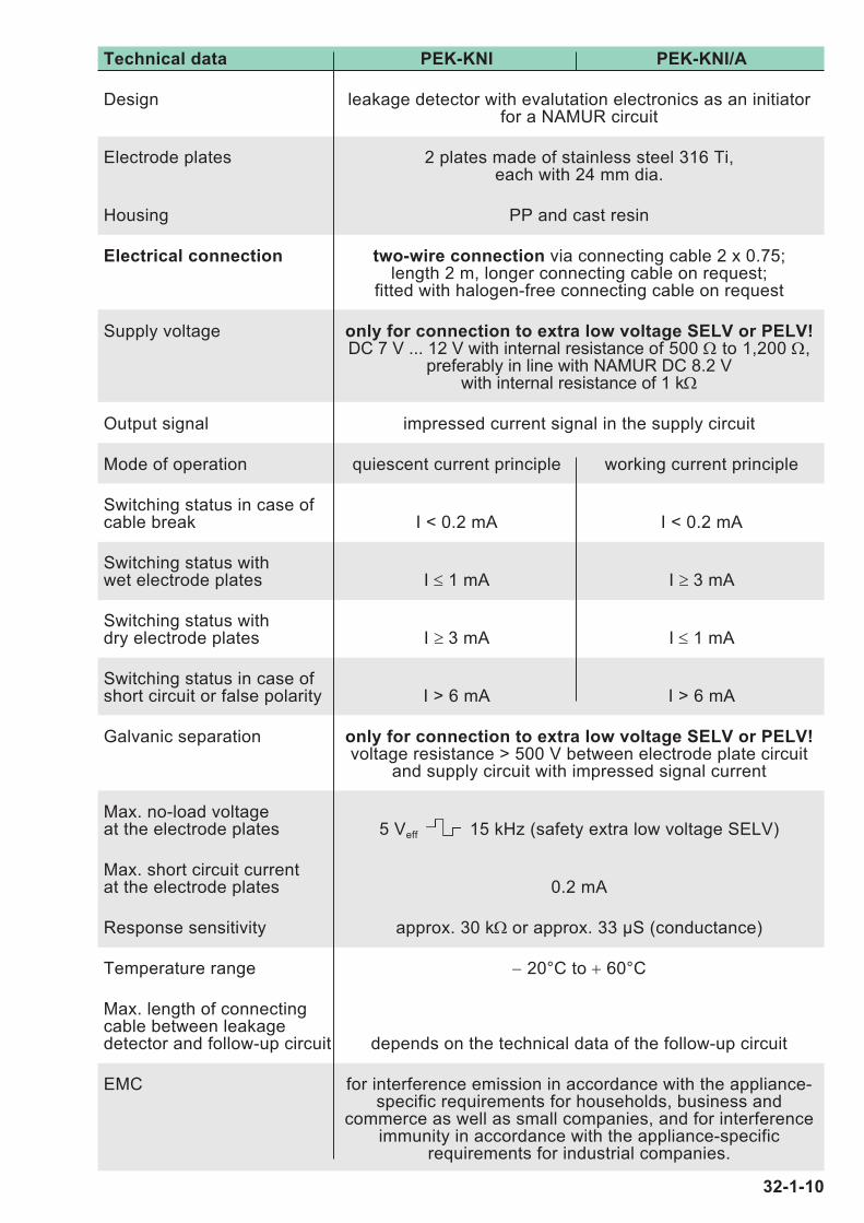
Technical data PEK-KNI PEK-KNI/A
Design leakage detector with evalutation electronics as an initiatorfor a NAMUR circuit
Electrode plates 2 plates made of stainless steel 316 Ti, each with 24 mm dia.
Housing PP and cast resin
Electrical connection two-wire connection via connecting cable 2 x 0.75;length 2 m, longer connecting cable on request;
fitted with halogen-free connecting cable on request
Supply voltage only for connection to extra low voltage SELV or PELV!DC 7 V ... 12 V with internal resistance of 500 Ω to 1,200 Ω,
preferably in line with NAMUR DC 8.2 Vwith internal resistance of 1 kΩ
Output signal impressed current signal in the supply circuit
Mode of operation quiescent current principle working current principle
Switching status in case ofcable break I < 0.2 mA I < 0.2 mA
Switching status withwet electrode plates I ≤ 1 mA I ≥ 3 mA
Switching status withdry electrode plates I ≥ 3 mA I ≤ 1 mA
Switching status in case ofshort circuit or false polarity I > 6 mA I > 6 mA
Galvanic separation only for connection to extra low voltage SELV or PELV!voltage resistance > 500 V between electrode plate circuit
and supply circuit with impressed signal current
Max. no-load voltageat the electrode plates 5 Veff 15 kHz (safety extra low voltage SELV)
Max. short circuit currentat the electrode plates 0.2 mA
Response sensitivity approx. 30 kΩ or approx. 33 μS (conductance)
Temperature range − 20°C to + 60°C
Max. length of connectingcable between leakagedetector and follow-up circuit depends on the technical data of the follow-up circuit
EMC for interference emission in accordance with the appliance-specific requirements for households, business and
commerce as well as small companies, and for interferenceimmunity in accordance with the appliance-specific
requirements for industrial companies.
32-1-10

74 46
~ 1
6
76
10
1020 20
Ø 24
Designed to signal the presence of a conductive liquidcaused, for example, by burst pipes.
Conductive plate electrodes WDX-... should only beused in normally dry environments. They must be installed on the floor in such a way that the sensor sidefaces downwards and the cable upwards.
The conductive plate electrode WDX-... is fitted with twoseparate electrodes in the form of two electrode plates: 1 control electrode and 1 earth electrode. As soon as a con-ductive liquid creates a conductive path between the twoelectrode plates, the switching statusof the leakage detector changes.
Conductive plate electrodesWDX-...
Plate electrodeWDX-KNI
~ 110
~ 120
Ø 6~ 150
3
~ 97
Ø 5
30
~ 135
Optional: mounting stand (diagrams with smaller scale
compared to below drawings)
32-1-11
Leckwatcher
• Leakage detectors forconnection to: a PLC or DDC unit,a small controller,a fieldbus connector ora network connector
• with integrated galvanicseparation of the sensorelectronics
Liqui-Switch
• Leakage detectors forconnection to: a PLC or DDC unit,a small controller,a fieldbus connector ora network connector
• with potential-free relaycontact (for switching e.g.a solenoid valve withextra low voltage SELVor PELV)
• with integrated galvanicseparation of the sensorelectronics
L-Pointer
• Leakage detectors forNAMUR circuits in linewith EN 50 227 (formerlyknown as DIN 19234) withthe option of detectingcable break, standbystatus, alarm status andshort circuit
• for connection to: NAMUR isolation amplifierorNAMUR fieldbus terminal
• with integrated galvanicseparation between sensor circuit and supplycurrent circuit with impressed signal current

Technical data WDX-SPS2 WDX-SPS3 WDX-SPS4
Design leakage detector with quiescent current / NC (break) contact
Electrode plates 2 plates made of stainless steel 316 Ti, each with 24 mm dia.
Housing PP and cast resin
Electrical connection two-wire connection three-wire connection four-wire connectionvia connecting cable via connecting cable via connecting cable
2 x 0.75 3 x 0.75 4 x 0.5
length 2 m, longer connecting cable on request;fitted with halogen-free connecting cable on request
Supply voltage only for connection to extra low voltage SELV or PELV!
DC 24 V ± 20 % AC/DC 12 ... 30 V; AC/DC 12 ... 30 V;via input resistance wire colours: wire colours:
2 kΩ ... 7.5 kΩ brown and blue brown and blue
Power consumption max. 0.5 W max. 0.5 VA max. 0.5 VA
Output evaluation based on PNP transistor output; potential-free reedthe magnitude of to be wired via contact with protective
power consumption the input resistance of resistance 62 Ω,the follow-up circuit max. loadof 2 kΩ ... 7.5 kΩ; AC/DC 30 V, 100 mA,wire colour: black 3 W; wire colours:
black and black
Short circuit protection present, at transistor output, reed contact atIk < 30 mA Ik < 30 mA output short circuit
proof for short periodsvia integrated protective
resistance of 62 Ω;however,
the reed contactis open if the supply
voltage of the sensor isincorrectly connected
Switching status without supply voltage Low signal Low signal reed contact open
Switching status withdry electrode plates power consumption PNP transistor output reed contact closed
> 2 mA, carries rectifiedgenerates High signal supply voltageat input resistance of = High signal
follow-up circuit
Switching status withwet electrode plates power consumption PNP transistor output reed contact open
< 0.7 mA, carries no voltagegenerates Low signal = Low signalat input resistance of
follow-up circuit
Cable break monitoring of connecting cable cable break monitoring due to the quiescent current
Galvanic separation only for connection to extra low voltage SELV or PELV!voltage resistance > 500 V between electrode plate circuit and
supply circuit supply circuit supply circuitand transistor output and output circuit
Max. no-load voltage at the electrode plates 5 Veff 600 Hz
Max. short circuit current at the electrode plates 0.2 mA
Response sensitivity approx. 30 kΩ or approx. 33 μS (conductance)
Temperature range − 20°C to + 60°C
Max. length of connectingcable between leakagedetector and follow-up circuit depends on the technical data of the follow-up circuit
EMC for interference emission in accordance with the appliance-specificrequirements for households, business and commerce as well as
small companies, and for interference immunity in accordance with the appliance-specific requirements for industrial companies.
32-1-12

Technical data WDX-LS4 WDX-LS4/A WDX-LS5
Design leakage detector with relay outputElectrode plates 2 plates made of stainless steel 316 Ti, each with 24 mm dia.Housing PP and cast resinElectrical connection four-wire four-wire five-wire
connection connection connectionvia connecting cable
4 x 0.5 4 x 0.5 5 x 0.5length 2 m, longer connecting cable on request;
fitted with halogen-free connecting cable on requestSupply voltage only for connection to extra low voltage SELV or PELV!
AC/DC 24 V ± 20 %, on request AC/DC 12 V ± 20 %wire colours: wire colours: wire colours:
brown and blue brown and blue black and blackPower consumption approx. 0.5 VAOutput potential-free potential-free potential-free
quiescent current working current changeover(NC) contact (NO) contact (CO) contact
max. load AC/DC 5 ... 24 V(extra low voltage SELV or PELV only);
AC/DC 1 mA ... 3 (1) Awire colours: wire colours:
black and black (grey) brown, grey a. blueSwitching status without supply voltage output relay output relay output relay
de-energised, de-energised, de-energised,output contact output contact changeover in pos. 1
open closed (grey and blue)Switching status with dry electrode plates output relay output relay output relay
energised, energised, energised,output contact output contact changeover in pos. 2
closed open (grey and brown)Switching status with wet electrode plates output relay output relay output relay
de-energised, de-energised, de-energised,output contact output contact changeover in pos. 1
open closed (grey and blue)Cable break monitoring of connecting cable cable break
monitoring due tothe quiescent
currentGalvanic separation only for connection to extra low voltage SELV or PELV!
voltage resistance > 500 V between electrode plate circuit,supply circuit and output circuit
Max. no-load voltage at the electrode plates 5 Veff 15 kHz (safety extra low voltage SELV)Max. short circuit current at the electrode plates 0.2 mAResponse sensitivity approx. 30 kΩ or approx. 33 μS (conductance)Temperature range − 20°C to + 60°CMax. length of connectingcable between leakagedetector and follow-up circuit depends on the technical data of the follow-up circuitEMC for interference emission in accordance with the appliance-
specific requirements for households, business andcommerce as well as small companies, and for interference
immunity in accordance with the appliance-specificrequirements for industrial companies.
32-1-13

Technical data WDX-KNI WDX-KNI/A
Design leakage detector with evalutation electronics as an initiatorfor a NAMUR circuit
Electrode plates 2 plates made of stainless steel 316 Ti,each with 24 mm dia.
Housing PP and cast resin
Electrical connection two-wire connection via connecting cable 2 x 0.75;length 2 m, longer connecting cable on request;
fitted with halogen-free connecting cable on request
Supply voltage only for connection to extra low voltage SELV or PELV!DC 7 V ... 12 V with internal resistance of 500 Ω to 1,200 Ω,
preferably in line with NAMUR DC 8.2 Vwith internal resistance of 1 kΩ
Output signal impressed current signal in the supply circuit
Mode of operation quiescent current principle working current principle
Switching status in case ofcable break I < 0.2 mA I < 0.2 mA
Switching status withwet electrode plates I ≤ 1 mA I ≥ 3 mA
Switching status withdry electrode plates I ≥ 3 mA I ≤ 1 mA
Switching status in case ofshort circuit or false polarity I > 6 mA I > 6 mA
Galvanic separation only for connection to extra low voltage SELV or PELV!voltage resistance > 500 V between electrode plate circuit
and supply circuit with impressed signal current
Max. no-load voltage at the electrode plates 5 Veff 15 kHz (safety extra low voltage SELV)
Max. short circuit current at the electrode plates 0.2 mA
Response sensitivity approx. 30 kΩ or approx. 33 μS (conductance)
Temperature range − 20°C to + 60°C
Max. length of connectingcable between leakagedetector and follow-up circuit depends on the technical data of the follow-up circuit
EMC for interference emission in accordance with the appliance-specific requirements for households, business and
commerce as well as small companies, and for interferenceimmunity in accordance with the appliance-specific
requirements for industrial companies.
32-1-14

Conductive wall-mounted electrodes WAE1-...
Designed to signal the presence of a conductive liquid caused, for example, by burstpipes.
Conductive wall-mounted electrodes WAE1-... should only be used in normally dryenvironments. They must be mounted on the wall in such a way that the electrode rod tipsare just slightly above the floor to be monitored.
The conductive wall-mounted electrode WAE1-... is fitted with two separate electrodes inthe form of two electrode rods: 1 control electrode and 1 earth electrode. As soon as a con-ductive liquid creates a conductive path between the two electrode rods, the switching status of the leakage detector changes.
32-1-15
Leckwatcher
• Leakage detectors forconnection to: a PLC or DDC unit,a small controller,a fieldbus connector ora network connector
• with integrated galvanicseparation of the sensorelectronics
Liqui-Switch
• Leakage detectors forconnection to: a PLC or DDC unit,a small controller,a fieldbus connector ora network connector
• with potential-free relaycontact (for switching e.g.a solenoid valve withextra low voltage SELVor PELV)
• with integrated galvanicseparation of the sensorelectronics
L-Pointer
• Leakage detectors forNAMUR circuits in linewith EN 50 227 (formerlyknown as DIN 19234) withthe option of detectingcable break, standbystatus, alarm status andshort circuit
• for connection to: NAMUR isolation amplifierorNAMUR fieldbus terminal
• with integrated galvanicseparation between sensor circuit and supplycurrent circuit with impressed signal current
Ø 4~ 25
53
~ 48
~ 28
65 x 50 x ~ 36
Ø 4
M16 x 1.5
38

Technical data WAE1-SPS2 WAE1-SPS3 WAE1-SPS4
Design leakage detector with quiescent current / NC (break) contact
Electrode rods 2 rods made of stainless steel 316 Ti, each with 4 mm dia.
Housing PC or PP
Electrical connection two-wire connection three-wire connection four-wire connectionvia connecting cable via connecting cable via connecting cable
2 x 0.75 3 x 0.75 4 x 0.5
length 2 m, longer connecting cable on request;fitted with halogen-free connecting cable on request
Supply voltage only for connection to extra low voltage SELV or PELV!
DC 24 V ± 20 % AC/DC 12 ... 30 V; AC/DC 12 ... 30 V;via input resistance wire colours: wire colours:
2 kΩ ... 7.5 kΩ brown and blue brown and blue
Power consumption max. 0.5 W max. 0.5 VA max. 0.5 VA
Output evaluation based on PNP transistor output; potential-free reedthe magnitude of to be wired via contact with protective
power consumption the input resistance of resistance 62 Ω,the follow-up circuit max. loadof 2 kΩ ... 7.5 kΩ; AC/DC 30 V, 100 mA,wire colour: black 3 W; wire colours:
black and black
Short circuit protection present, at transistor output, reed contact atIk < 30 mA Ik < 30 mA output short circuit
proof for short periodsvia integrated protective
resistance of 62 Ω;the reed contact
is open if the supplyvoltage of the sensor isincorrectly connected
Switching status withoutsupply voltage Low signal Low signal reed contact open
Switching status withdry electrode rods power consumption PNP transistor output reed contact closed
> 2 mA, carries rectifiedgenerates High signal supply voltageat input resistance of = High signal
follow-up circuit
Switching status withwet electrode rods power consumption PNP transistor output reed contact open
< 0.7 mA, carries no voltagegenerates Low signal = Low signalat input resistance of
follow-up circuit
Cable break monitoring of connecting cable cable break monitoring due to the quiescent current
Galvanic separation only for connection to extra low voltage SELV or PELV!voltage resistance > 500 V between electrode rod circuit and
supply circuit supply circuit supply circuitand transistor output and output circuit
Max. no-load voltage at the electrode rods 5 Veff 600 Hz
Max. short circuit current at the electrode rods 0.2 mA
Response sensitivity approx. 30 kΩ or approx. 33 μS (conductance)
Temperature range − 20°C to + 60°C
Max. length of connectingcable between leakagedetector and follow-up circuit depends on the technical data of the follow-up circuit
EMC for interference emission in accordance with the appliance-specificrequirements for households, business and commerce as well as
small companies, and for interference immunity in accordance with the appliance-specific requirements for industrial companies.
32-1-16

Technical data WAE1-LS4 WAE1-LS4/A WAE1-LS5
Design leakage detector with relay outputElectrode rods 2 rods made of stainless steel 316 Ti, each with 4 mm dia.Housing PC or PPElectrical connection four-wire four-wire five-wire
connection connection connectionvia connecting cable
4 x 0.5 4 x 0.5 5 x 0.5length 2 m, longer connecting cable on request;
fitted with halogen-free connecting cable on requestSupply voltage only for connection to extra low voltage SELV or PELV!
AC/DC 24 V ± 20 %, on request AC/DC 12 V ± 20 %wire colours: wire colours: wire colours:
brown and blue brown and blue black and blackPower consumption approx. 0.5 VAOutput potential-free potential-free potential-free
quiescent current working current changeover(NC) contact (NO) contact (CO) contact
max. load AC/DC 5 ... 24 V (extra low voltage SELV or PELV only);
AC/DC 1 mA ... 3 (1) Awire colours: wire colours:
black and black (grey) brown, grey a. blueSwitching status without supply voltage output relay output relay output relay
de-energised, de-energised, de-energised,output contact output contact changeover in pos. 1
open closed (grey and blue)Switching status with dry electrode rods output relay output relay output relay
energised, energised, energised,output contact output contact changeover in pos. 2
closed open (grey and brown)Switching status with wet electrode rods output relay output relay output relay
de-energised, de-energised, de-energised, output contact output contact changeover in pos. 1
open closed (grey and blue)Cable break monitoring of connecting cable cable break
monitoring due tothe quiescent
currentGalvanic separation only for connection to extra low voltage SELV or PELV!
voltage resistance > 500 V between electrode rod circuit,supply circuit and output circuit
Max. no-load voltage at the electrode rods 5 Veff 15 kHz (safety extra low voltage SELV)Max. short circuit current at the electrode rods 0.2 mAResponse sensitivity approx. 30 kΩ or approx. 33 μS (conductance)Temperature range − 20°C to + 60°CMax. length of connectingcable between leakagedetector and follow-up circuit depends on the technical data of the follow-up circuitEMC for interference emission in accordance with the appliance-
specific requirements for households, business and commerce as well as small companies, and for interference
immunity in accordance with the appliance-specific requirements for industrial companies.
32-1-17

Technical data WAE1-KNI WAE1-KNI/A
Design leakage detector with evalutation electronics as an initiator for a NAMUR circuit
Electrode rods 2 rods made of stainless steel 316 Ti, each with 4 mm dia.
Housing PC or PP
Electrical connection two-wire connection via connecting cable 2 x 0.75;length 2 m, longer connecting cable on request;
fitted with halogen-free connecting cable on request
Supply voltage only for connection to extra low voltage SELV or PELV!DC 7 V ... 12 V with internal resistance of 500 Ω to 1,200 Ω,
preferably in line with NAMUR DC 8.2 Vwith internal resistance of 1 kΩ
Output signal impressed current signal in the supply circuit
Mode of operation quiescent current principle working current principle
Switching status in case ofcable break I < 0.2 mA I < 0.2 mA
Switching status withwet electrode rods I ≤ 1 mA I ≥ 3 mA
Switching status withdry electrode rods I ≥ 3 mA I ≤ 1 mA
Switching status in case ofshort circuit or false polarity I > 6 mA I > 6 mA
Galvanic separation only for connection to extra low voltage SELV or PELV!voltage resistance > 500 V between electrode rod circuit
and supply circuit with impressed signal current
Max. no-load voltage at the electrode rods 5 Veff 15 kHz (safety extra low voltage SELV)
Max. short circuit current at the electrode rods 0.2 mA
Response sensitivity approx. 30 kΩ or approx. 33 μS (conductance)
Temperature range − 20°C to + 60°C
Max. length of connectingcable between leakagedetector and follow-up circuit depends on the technical data of the follow-up circuit
EMC for interference emission in accordance with the appliance-specific requirements for households, business and
commerce as well as small companies, and for interference immunity in accordance with the appliance-specific
requirements for industrial companies.
32-1-18

S 2 AM-...
M 20 x 1.5
perspectiverotated by 90°
rod
leng
th L
, max
. 2,5
00 m
m
Ø 4<_ 16
~ 120~
103
1215
G1
Designed to signal the presence of a conductive liquid caused, for example, by burstpipes.
Conductive rod electrodes should only be used in normally dry environments. Theycan be installed from the top or from the side. In both cases, it must be ensured that theelectrode rod tips are just slightly above the floor to be monitored.
The conductive rod electrodes S 2 M/PP-..., S 2 M/PVDF-... and S 2 AM-... are fitted with twoseparate electrodes in the form of two electrode rods: 1 control electrode and 1 earth elec-trode. As soon as a conductive liquid creates a conductive path between the two electroderods, the switching status of the leakage detector changes.
2516
~ 10
3
SW 36
G1
M 20 x 1.5
perspectiverotated by 90°
rod
leng
th L
, max
. 2,5
00 m
m
<_ 16Ø 4
~ 120
Conductive rod electrodesS 2 M/PP..., S 2 M/PVDF-... and S 2 AM-...
S 2 M/PP-...or S 2 M/PVDF-...
32-1-19
Leckwatcher
• Leakage detectors forconnection to: a PLC or DDC unit,a small controller,a fieldbus connector ora network connector
• with integrated galvanicseparation of the sensorelectronics
Liqui-Switch
• Leakage detectors forconnection to: a PLC or DDC unit,a small controller,a fieldbus connector ora network connector
• with potential-free relaycontact (for switching e.g.a solenoid valve withextra low voltage SELVor PELV)
• with integrated galvanicseparation of the sensorelectronics
L-Pointer
• Leakage detectors forNAMUR circuits in linewith EN 50 227 (formerlyknown as DIN 19234) withthe option of detectingcable break, standbystatus, alarm status andshort circuit
• for connection to: NAMUR isolation amplifierorNAMUR fieldbus terminal
• with integrated galvanicseparation between sensor circuit and supplycurrent circuit with impressed signal current

Technical data S 2 M/PP-SPS2 S 2 M/PP-SPS3 S 2 M/PP-SPS4S 2 M/PVDF-SPS2 S 2 M/PVDF-SPS3 S 2 M/PVDF-SPS4
S 2 AM-SPS2 S 2 AM-SPS3 S 2 AM-SPS4
Design leakage detector with quiescent current / NC (break) contactElectrode rods 2 rods made of stainless steel 316 Ti;
other materials (e. g. titanium, Hastelloy, Monel or tantalum) on request;each with 4 mm dia., covered with shrinkdown tubing made of
polyolefin (S 2 M/PP-SPS. and S 2 AM-SPS.) or PVDF (S 2 M/PVDF-SPS.)Length on request (measured from nipple sealing surface) Max. lengths 2,500 mmScrew-in nipple G1; S 2 M/PP-SPS.: PP; S 2 M/PVDF-SPS.: PVDF;
S 2 AM-SPS.: stainless steel 316 Ti, other materials on requestElectrical connection two-wire connection three-wire connection four-wire connection
via 2-pole via 3-pole via 4-poleterminal block terminal block terminal block
for max. 2.5 mm² for max. 2.5 mm² for max. 2.5 mm²in the PP connection head with cable entry M 20 x 1.5,
protection class IP 54Supply voltage only for connection to extra low voltage SELV or PELV!
DC 24 V ± 20 % AC/DC 12 ... 30 V AC/DC 12 ... 30 Vvia input resistance
2 kΩ ... 7.5 kΩPower consumption max. 0.5 W max. 0.5 VA max. 0.5 VAOutput evaluation based on PNP transistor output; potential-free reed
the magnitude of to be wired via contact with protectivepower consumption the input resistance of resistance 62 Ω,
the follow-up circuit max. loadof 2 kΩ ... 7.5 kΩ AC/DC 30 V, 100 mA,
3 W;Short circuit protection present, at transistor output, reed contact at
Ik < 30 mA Ik < 30 mA output short circuitproof for short periods
resistance of 62 Ω;however,
the reed contactis open if the supply
voltage of the sensor isincorrectly connected
Switching status without supply voltage Low signal Low signal reed contact openSwitching status withdry electrode rods power consumption PNP transistor output reed contact closed
> 2 mA, carries rectifiedgenerates High signal supply voltageat input resistance of = High signal
follow-up circuitSwitching status withwet electrode rods power consumption PNP transistor output reed contact open
< 0.7 mA, carries no voltagegenerates Low signal = Low signalat input resistance of
follow-up circuitCable break monitoring of connecting cable cable break monitoring due to the quiescent currentGalvanic separation only for connection to extra low voltage SELV or PELV!
voltage resistance > 500 V between electrode rod circuit andsupply circuit supply circuit supply circuit
and transistor output and output circuitMax. no-load voltage at the electrode rods 5 Veff 600 HzMax. short circuit current at the electrode rods 0.2 mAResponse sensitivity approx. 30 kΩ or approx. 33 μS (conductance)Temperature range − 20°C to + 60°CMax. length of connectingcable between leakagedetector and follow-up circuit depends on the technical data of the follow-up circuitEMC for interference emission in accordance with the appliance-specific
requirements for households, business and commerce as well assmall companies, and for interference immunity in accordance with
the appliance-specific requirements for industrial companies.
32-1-20

Technical data S 2 M/PP-LS4 S 2 M/PP-LS4/A S 2 M/PP-LS5S 2 M/PVDF-LS4 S 2 M/PVDF-LS4/A S 2 M/PVDF-LS5
S 2 AM-LS4 S 2 AM-LS4/A S 2 AM-LS5
Design leakage detector with relay outputElectrode rods 2 rods made of stainless steel 316 Ti; other materials
(e. g. titanium, Hastelloy, Monel or tantalum) on request;each with 4 mm dia.,
covered with shrinkdown tubing made of polyolefin(S 2 M/PP-LS... and S 2 AM-LS...) or PVDF (S 2 M/PVDF-LS...)
Length on request (measured from nipple sealing surface)Max. lengths 2,500 mmScrew-in nipple G1; S 2 M/PP-LS...: PP; S 2 M/PVDF-LS...: PVDF;
S 2 AM-LS...: stainless steel 316 Ti, other materials on requestElectrical connection four-wire connection five-wire
connectionvia 4-pole terminal block via 5-pole
terminal blockfor max. 2.5 mm² in the PP connection head with cable entry
M 20 x 1.5, protection class IP 54Supply voltage only for connection to extra low voltage SELV or PELV!
AC/DC 24 V ± 20 %, on request AC/DC 12 V ± 20 %Power consumption approx. 0.5 VAOutput potential-free potential-free potential-free
quiescent current working current changeover(NC) contact (NO) contact (CO) contact
max. load AC/DC 5 ... 24 V (extra low voltage SELV or PELV only); AC/DC 1 mA ... 3 (1) A
Switching status withoutsupply voltage output relay output relay output relay
de-energised, de-energised, de-energised,output contact output contact changeover
open closed in position 1Switching status withdry electrode rods output relay output relay output relay
energised, energised, energised,output contact output contact changeover
closed open in position 2Switching status withwet electrode rods output relay output relay output relay
de-energised, de-energised, de-energised,output contact output contact changeover
open closed in position 1Cable break monitoring of connecting cable cable break
monitoring due tothe quiescent
currentGalvanic separation only for connection to extra low voltage SELV or PELV!
voltage resistance > 500 V between electrode rod circuit,supply circuit and output circuit
Max. no-load voltageat the electrode rods 5 Veff 15 kHz (safety extra low voltage SELV)Max. short circuit currentat the electrode rods 0.2 mAResponse sensitivity approx. 30 kΩ or approx. 33 μS (conductance)Temperature range − 20°C to + 60°CMax. length of connectingcable between leakagedetector and follow-up circuit depends on the technical data of the follow-up circuitEMC for interference emission in accordance with the appliance-
specific requirements for households, business andcommerce as well as small companies, and for interference
immunity in accordance with the appliance-specificrequirements for industrial companies.
32-1-21

Technical data S 2 M/PP-KNI S 2 M/PP-KNI/AS 2 M/PVDF-KNI S 2 M/PVDF-KNI/A
S 2 AM-KNI S 2 AM-KNI/A
Design leakage detector with evalutation electronics as an initiator for a NAMUR circuit
Electrode rods 2 rods made of stainless steel 316 Ti; other materials(e.g. titanium, Hastelloy, Monel or tantalum) on request;
each with 4 mm dia., covered with shrinkdown tubing made of polyolefin
(S 2 M/PP-KNI... and S 2 AM-KNI...) or PVDF S 2 M/PVDF-KNI...)
Length on request (measured from nipple sealing surface)
Max. length 2,500 mm
Screw-in nipple G1;S 2 M/PP-KNI...: PP;
S 2 M/PVDF-KNI...: PVDF;S 2 AM-KNI...: stainless steel 316 Ti,
other materials on request
Electrical connection two-wire connection via 2-pole terminal blockfor max. 2,5 mm² in the PP connection head with cable entry
M 20 x 1.5, protection class IP 54
Supply voltage only for connection to extra low voltage SELV or PELV!DC 7 V ... 12 V with internal resistance of 500 Ω to 1,200 Ω,
preferably in line with NAMUR DC 8.2 Vwith internal resistance of 1 kΩ
Output signal impressed current signal in the supply circuit
Mode of operation quiescent current principle working current principle
Switching status in case ofcable break I < 0.2 mA I < 0.2 mA
Switching status withwet electrode rods I ≤ 1 mA I ≥ 3 mA
Switching statusdry electrode rods I ≥ 3 mA I ≤ 1 mA
Switching status in case ofshort circuit or false polarity I > 6 mA I > 6 mA
Galvanic separation only for connection to extra low voltage SELV or PELV!voltage resistance > 500 V between electrode rod circuit
and supply circuit with impressed signal current
Max. no-load voltage at the electrode rods 5 Veff 15 kHz (safety extra low voltage SELV)
Max. short circuit current at the electrode rods 0.2 mA
Response sensitivity approx. 30 kΩ or approx. 33 μS (conductance)
Temperature range − 20°C to + 60°C
Max. length of connectingcable between leakagedetector and follow-up circuit depends on the technical data of the follow-up circuit
EMC for interference emission in accordance with the appliance-specific requirements for households, business and
commerce as well as small companies, and for interference immunity in accordance with the appliance-specific
requirements for industrial companies.
32-1-22

EHW3-SPS.
EHE-SPS. with mountingstand
Conductive suspension electrodesEHE-... and EHW3-...
Designed to signal the presence of a conductive liquid caused, for example, by burstpipes.
Conductive suspension electrodes EHE-... and EHW-... should only be used in nor-mally dry environments. They must be mounted in suspended mode from above (or in thecase of the type EHE-... in an upright position using a mounting stand) in such a way thatthe sensor electrodes are just slightly above the floor to be monitored.
In the conductive suspension electrode EHE-..., the metal housing and a concentrically positioned electrode rod in the housing form an electrode pair; the conductive suspensionelectrode EHW3-... is fitted with two separate electrodes in the form of two electrode rods: 1 control electrode and 1 earth electrode. As soon as a conductive liquid creates a conduc-tive path between the control electrode and the earth electrode, the switching status of theleakage detector changes.
32-1-23
Leckwatcher
• Leakage detectors forconnection to: a PLC or DDC unit,a small controller,a fieldbus connector ora network connector
• with integrated galvanicseparation of the sensorelectronics
Liqui-Switch
• Leakage detectors forconnection to: a PLC or DDC unit,a small controller,a fieldbus connector ora network connector
• with potential-free relaycontact (for switching e.g.a solenoid valve withextra low voltage SELVor PELV)
• with integrated galvanicseparation of the sensorelectronics
L-Pointer
• Leakage detectors forNAMUR circuits in linewith EN 50 227 (formerlyknown as DIN 19234) withthe option of detectingcable break, standbystatus, alarm status andshort circuit
• for connection to: NAMUR isolation amplifierorNAMUR fieldbus terminal
• with integrated galvanicseparation between sensor circuit and supplycurrent circuit with impressed signal current

EHE-... with mounting stand
EHE-... EHW3-...
15
Ø 6
R 165
3 x
120°
Ø 28
View Areduced
55
115 ~
145
A
Stand (optional)
with theseor anyother
dimensions
1
120 ~
147
Ø 4
Ø 4
0
13
Ø 3
2
Ø 1
0
37
Ø 8
Ø 2
5Ø
28
115
Ø 28
~ 14
5
8
32-1-24

Technical data EHE-SPS2 EHE-SPS3 EHE-SPS4
Design leakage detector with quiescent current / NC (break) contact
Electrode rod stainless steel 316 Ti, with 8 mm dia.
Housing stainless steel 316 Ti and PTFE
Electrical connection two-wire connection three-wire connection four-wire connectionvia connecting cable via connecting cable via connecting cable
2 x 0.75 3 x 0.75 4 x 0.5
length 2 m, longer connecting cable on request;fitted with halogen-free connecting cable on request
Supply voltage only for connection to extra low voltage SELV or PELV!
DC 24 V ± 20 % AC/DC 12 ... 30 V; AC/DC 12 ... 30 V;via input resistance wire colours: wire colours:
2 kΩ ... 7.5 kΩ brown and blue brown and blue
Power consumption max. 0.5 W max. 0.5 VA max. 0.5 VA
Output evaluation based on PNP transistor output; potential-free reedthe magnitude of to be wired via contact with protective
power consumption the input resistance of resistance 62 Ω,the follow-up circuit max. load of 2 kΩ ... 7.5 kΩ; AC/DC 30 V, 100 mA,wire colour: black 3 W; wire colours:
black and black
Short circuit protection present, at transistor output, reed contact atIk < 30 mA Ik < 30 mA output short circuit
proof for short periodsvia integrated protective
resistance of 62 Ω;however,
the reed contactis open if the supply
voltage of the sensor isincorrectly connected
Switching status without supply voltage Low signal Low signal reed contact open
Switching status withdry electrode rod + housing power consumption PNP transistor output reed contact closed
> 2 mA, carries rectifiedgenerates High signal supply voltageat input resistance of = High signal
follow-up circuit
Switching status withwet electrode rod + housing power consumption PNP transistor output reed contact open
< 0.7 mA, carries no voltagegenerates Low signal = Low signalat input resistance of
follow-up circuit
Cable break monitoring of connecting cable cable break monitoring due to the quiescent current
Galvanic separation only for connection to extra low voltage SELV or PELV!voltage resistance > 500 V between electrode rod + housing circuit and
supply circuit supply circuit supply circuitand transistor output and output circuit
Max. no-load voltage at electrode rod + housing 5 Veff 600 Hz
Max. short circuit currentat electrode rod + housing 0.2 mA
Response sensitivity approx. 30 kΩ or approx. 33 μS (conductance)
Temperature range − 20°C to + 60°C
Max. length of connectingcable between leakagedetector and follow-up circuit depends on the technical data of the follow-up circuit
EMC for interference emission in accordance with the appliance-specificrequirements for households, business and commerce as well as
small companies, and for interference immunity in accordance withthe appliance-specific requirements for industrial companies.
32-1-25
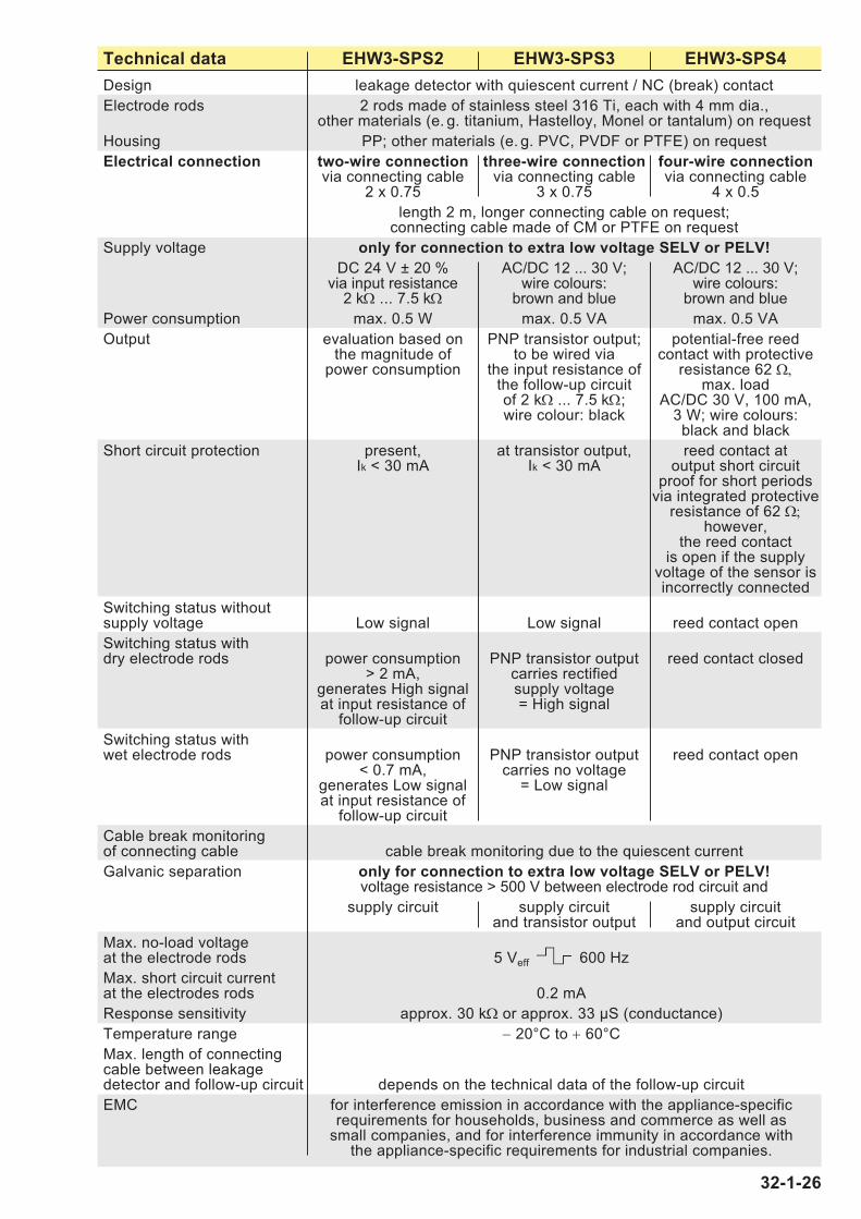
Technical data EHW3-SPS2 EHW3-SPS3 EHW3-SPS4
Design leakage detector with quiescent current / NC (break) contact
Electrode rods 2 rods made of stainless steel 316 Ti, each with 4 mm dia.,other materials (e. g. titanium, Hastelloy, Monel or tantalum) on request
Housing PP; other materials (e. g. PVC, PVDF or PTFE) on request
Electrical connection two-wire connection three-wire connection four-wire connectionvia connecting cable via connecting cable via connecting cable
2 x 0.75 3 x 0.75 4 x 0.5
length 2 m, longer connecting cable on request;connecting cable made of CM or PTFE on request
Supply voltage only for connection to extra low voltage SELV or PELV!
DC 24 V ± 20 % AC/DC 12 ... 30 V; AC/DC 12 ... 30 V;via input resistance wire colours: wire colours:
2 kΩ ... 7.5 kΩ brown and blue brown and blue
Power consumption max. 0.5 W max. 0.5 VA max. 0.5 VA
Output evaluation based on PNP transistor output; potential-free reedthe magnitude of to be wired via contact with protective
power consumption the input resistance of resistance 62 Ω,the follow-up circuit max. loadof 2 kΩ ... 7.5 kΩ; AC/DC 30 V, 100 mA,wire colour: black 3 W; wire colours:
black and black
Short circuit protection present, at transistor output, reed contact atIk < 30 mA Ik < 30 mA output short circuit
proof for short periodsvia integrated protective
resistance of 62 Ω;however,
the reed contactis open if the supply
voltage of the sensor isincorrectly connected
Switching status without supply voltage Low signal Low signal reed contact open
Switching status withdry electrode rods power consumption PNP transistor output reed contact closed
> 2 mA, carries rectifiedgenerates High signal supply voltageat input resistance of = High signal
follow-up circuit
Switching status withwet electrode rods power consumption PNP transistor output reed contact open
< 0.7 mA, carries no voltagegenerates Low signal = Low signalat input resistance of
follow-up circuit
Cable break monitoringof connecting cable cable break monitoring due to the quiescent current
Galvanic separation only for connection to extra low voltage SELV or PELV!voltage resistance > 500 V between electrode rod circuit and
supply circuit supply circuit supply circuitand transistor output and output circuit
Max. no-load voltageat the electrode rods 5 Veff 600 Hz
Max. short circuit currentat the electrodes rods 0.2 mA
Response sensitivity approx. 30 kΩ or approx. 33 μS (conductance)
Temperature range − 20°C to + 60°C
Max. length of connectingcable between leakagedetector and follow-up circuit depends on the technical data of the follow-up circuit
EMC for interference emission in accordance with the appliance-specificrequirements for households, business and commerce as well as
small companies, and for interference immunity in accordance with the appliance-specific requirements for industrial companies.
32-1-26

Technical data EHE-LS4 EHE-LS4/A EHE-LS5EHW3-LS4 EHW3-LS4/A EHW3-LS5
Design leakage detector with relay outputElectrode pair EHE-...: 1 rod made of stainless steel 316 Ti, with 8 mm dia.,
and a housing made of stainless steel 316 TiEHW3-...: 2 rods made of stainless steel 316 Ti,
other materials (e. g. titanium, Hastelloy, Monel or tantalum) on request
Housing EHE-...: stainless steel 316 Ti and PTFEEHW3-...: PP,
other materials (e. g. PVDF or PTFE) on requestElectrical connection four-wire four-wire five-wire
connection connection connectionvia connecting cable
4 x 0.5 4 x 0.5 5 x 0.5length 2 m, longer connecting cable on request;
fitted with halogen-free connecting cable on requestSupply voltage only for connection to extra low voltage SELV or PELV!
AC/DC 24 V ± 20 %, on request AC/DC 12 V ± 20 %wire colours: wire colours: wire colours:
brown and blue brown and blue black and blackPower consumption approx. 0.5 VAOutput potential-free potential-free potential-free
quiescent current working current changeover (NC) contact (NO) contact (CO) contact
max. load AC/DC 5 ... 24 V (extra low voltage SELV or PELV only);
AC/DC 1 mA ... 3 (1) Awire colours: wire colours:
black and black (grey) brown, grey a. blueSwitching status without supply voltage output relay output relay output relay
de-energised, de-energised, de-energised,output contact output contact changeover in pos. 1
open closed (grey and blue)Switching status with dry electrode pair output relay output relay output relay
energised, energised, energised,output contact output contact changeover in pos. 2
closed open (grey and brown)Switching status with wet electrode pair output relay output relay output relay
de-energised, de-energised, de-energised,output contact output contact changeover in pos. 1
open closed (grey and blue)Cable break monitoring of connecting cable cable break
monitoring due tothe quiescent
currentGalvanic separation only for connection to extra low voltage SELV or PELV!
voltage resistance > 500 V between electrode pair circuit,supply circuit and output circuit
Max. no-load voltage at the electrode pair 5 Veff 15 kHz (safety extra low voltage SELV)Max. short circuit current at the electrode pair 0.2 mAResponse sensitivity approx. 30 kΩ or approx. 33 μS (conductance)Temperature range − 20°C to + 60°CMax. length of connectingcable between leakagedetector and follow-up circuit depends on the technical data of the follow-up circuitEMC for interference emission in accordance with the appliance-
specific requirements for households, business andcommerce as well as small companies, and for interference
immunity in accordance with the appliance-specificrequirements for industrial companies.
32-1-27

Technical data EHE-KNI EHE-KNI/AEHW3-KNI EHW3-KNI/A
Design leakage detector with evalutation electronics as an initiator for a NAMUR circuit
Electrode pair EHE-...: 1 rod made of stainless steel 316 Ti, with 8 mm dia.,and a housing made of stainless steel 316 Ti
EHW3-...: 2 rods made of stainless steel 316 Ti,other materials
(e. g. titanium, Hastelloy, Monel or tantalum) on request
Housing EHE-...: stainless steel 316 Ti and PTFE
EHW3-...: PP, other materials (e. g. PVDF or PTFE) on request
Electrical connection two-wire connection via connecting cable 2 x 0.75;length 2 m, longer connecting cable on request;
fitted with halogen-free connecting cable on request
Supply voltage only for connection to extra low voltage SELV or PELV!DC 7 V ... 12 V with internal resistance of 500 Ω to 1,200 Ω,
preferably in line with NAMUR DC 8.2 Vwith internal resistance of 1 kΩ
Output signal impressed current signal in the supply circuit
Mode of operation quiescent current principle working current principle
Switching status in case ofcable break I < 0.2 mA I < 0.2 mA
Switching status withwet electrode pair I ≤ 1 mA I ≥ 3 mA
Switching status withdry electrode pair I ≥ 3 mA I ≤ 1 mA
Switching status in case ofshort circuit or false polarity I > 6 mA I > 6 mA
Galvanic separation only for connection to extra low voltage SELV or PELV!voltage resistance > 500 V between electrode pair circuit
and supply circuit with impressed signal current
Max. no-load voltage at the electrode pair 5 Veff 15 kHz (safety extra low voltage SELV)
Max. short circuit current at the electrode pair 0.2 mA
Response sensitivity approx. 30 kΩ or approx. 33 μS (conductance)
Temperature range − 20°C to + 60°C
Max. length of connectingcable between leakagedetector and follow-up circuit depends on the technical data of the follow-up circuit
EMC for interference emission in accordance with the appliance-specific requirements for households, business and
commerce as well as small companies, and for interference immunity in accordance with the appliance-specific
requirements for industrial companies.
32-1-28

Leckwatcher
• Leakage detectors for connection to: a PLC or DDC unit,a small controller,a fieldbus connector ora network connector
• with integrated galvanic separation of the sensor electronics
Conductive cable electrodesKE-SPS.
32-1-29
Designed to signal the presence of a conductive liquid caused, for example, byburst pipes.
Conductive cable electrodes KE-SPS.should only be used in normally dry environments. They can be used onfloors, false ceilings, alongside pipes or indouble-pipe systems. They should be installed at the lowest point of the potentialhazard area which they are intended tomonitor.
The conductive cable electrodes KE-SPS.are fitted with two separate electrodes inthe form of two sensor cables: 1 controlelectrode and 1 earth electrode. As soonas a conductive liquid creates a conductivepath between the two sensor cables, theswitching status of the leakage detectorchanges.
Each of the two sensor cables consists ofa stainless steel rope core and a protectivesheath made of polyester. This protectivesheath is designed to prevent contact ofthe stainless steel ropes with one anotheror with an electrically conductive surface(e.g. steel tub, steel pipe etc.) and thus toavoid false alarms, whilst allowing leakageliquid to penetrate throught to the stainlesssteel ropes.
The two sensor cables of the cable elec-trode must be mounted parallel to one another at a distance ≤ 2 cm using thesensor cable spacers, as a greater orlesser spacing affects the response levelof the system in the event of leakage.
housing made ofPP with cablebreak monitoringunit
connectors
sensor cablespacer
~ 40
~ 40
~ 20
~ 58
~ 14
5
~ 63
sens
or c
able
s: s
tand
ard
leng
th 2
met
res,
long
er o
n re
ques
t
≤25
0≤
250
≤ 20
~ 75
connecting cable
housing madeof PC or PP
d = 36
d = 20
~ 65
rope made ofstainless steelcovered by ahalogen-free protective polyester sheath, Ø ~ 3 mm
KE-SPS.

Technical data KE-SPS2 KE-SPS3 KE-SPS4
Design leakage detector with quiescent current / NC (break) contactSensor cables 2 ropes made of stainless steel 316 Ti, each with 3 mm dia.,
each covered by a halogen-free protective polyester sheath;length: 2 m each, longer on request
Max. length of sensorcables when laid in arelatively straight line 100 metres; if the sensor cables are wound around a pipe or tank,
the possible length may be considerably shorter depending onthe type and method of laying
Electrode head PC or PPElectrical connection two-wire connection three-wire connection four-wire connection
via connecting cable via connecting cable via connecting cable2 x 0.75 3 x 0.75 4 x 0.5
length 2 m, longer connecting cable on request;fitted with halogen-free connecting cable on request
Supply voltage only for connection to extra low voltage SELV or PELV!DC 24 V ± 20 % AC/DC 12 ... 30 V; AC/DC 12 ... 30 V;
via input resistance wire colours: wire colours:2 kΩ ... 7.5 kΩ brown and blue brown and blue
Power consumption max. 0.5 W max. 0.5 VA max. 0.5 VAOutput evaluation based on PNP transistor output; potential-free reed
the magnitude of to be wired via contact with protectivepower consumption the input resistance of resistance 62 Ω,
the follow-up circuit max. load of 2 kΩ ... 7.5 kΩ; AC/DC 30 V, 100 mA,wire colour: black 3 W; wire colours:
black and blackShort circuit protection present, at transistor output, reed contact at
Ik < 30 mA Ik < 30 mA output short circuitproof for short periods
via integrated protectiveresistance of 62 Ω;
however,the reed contact
is open if the supplyvoltage of the sensor isincorrectly connected
Switching status withoutsupply voltage Low signal Low signal reed contact openSwitching status withdry sensor cables power consumption PNP transistor output reed contact closed
> 2 mA, carries rectifiedgenerates High signal supply voltageat input resistance of = High signal
follow-up circuitSwitching status withwet sensor cables power consumption PNP transistor output reed contact open
< 0.7 mA, carries no voltagegenerates Low signal = Low signalat input resistance of
follow-up circuitCable break monitoringof sensor cables via cable break monitoring unit Z-4V7 at the end of the sensor cablesSwitching status withbreak in sensor cables line power consumption PNP transistor output reed contact open
< 0,7 mA, carries no voltagegenerates Low signal = Low signalat input resistance of
follow-up circuitCable break monitoringof connecting cable cable break monitoring due to the quiescent currentGalvanic separation only for connection to extra low voltage SELV or PELV!
voltage resistance > 500 V between sensor cable circuit andsupply circuit supply circuit supply circuit
and transistor output and output circuitMax. no-load voltageat the sensor cables 10 Veff 60 HzMax. short circuit currentat the sensor cables 0.1 mAResponse sensitivity approx. 30 kΩ or approx. 33 μS (conductance)Temperature range − 20°C to + 60°CMax. length of connectingcable between leakagedetector and follow-up circuit depends on the technical data of the follow-up circuitEMC see page 32-1-26
32-1-30
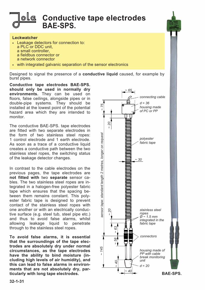
Conductive tape electrodesBAE-SPS.
Leckwatcher
• Leakage detectors for connection to: a PLC or DDC unit,a small controller,a fieldbus connector ora network connector
• with integrated galvanic separation of the sensor electronics
Designed to signal the presence of a conductive liquid caused, for example byburst pipes.
housing made ofPP with cablebreak monitoringunit
connectors
~ 40
~ 40
~ 58
~ 14
5
~ 63
~ 20
~ 20
~ 75
connecting cable
d = 36housing madeof PC or PP
~ 30
d = 20
~ 65
BAE-SPS.
stainless steelropes Ø ~ 1.5 mm integrated in thefabric tape
polyester fabric tape
32-1-31
Conductive tape electrodes BAE-SPS.should only be used in normally dry environments. They can be used onfloors, false ceilings, alongside pipes or indouble-pipe systems. They should be installed at the lowest point of the potentialhazard area which they are intended tomonitor.
The conductive BAE-SPS. tape electrodesare fitted with two separate electrodes inthe form of two stainless steel ropes:1 control electrode and 1 earth electrode.As soon as a trace of a conductive liquidcreates a conductive path between the twostainless steel ropes, the switching statusof the leakage detector changes.
In contrast to the cable electrodes on theprevious pages, the tape electrodes arenot fitted with two separate sensor ca-bles. The two stainless steel ropes are in-tegrated in a halogen-free polyester fabrictape which ensures that the spacing be-tween them remains constant. This poly-ester fabric tape is designed to preventcontact of the stainless steel ropes withone another or with an electrically conduc-tive surface (e.g. steel tub, steel pipe etc.)and thus to avoid false alarms, whilst allowing leakage liquid to penetratethrough to the stainless steel ropes.
To avoid false alarms, it is essentialthat the surroundings of the tape elec-trodes are absolutely dry under normalcircumstances, as the tape electrodeshave the ability to bind moisture (in-cluding high levels of air humidity), andthis can lead to false alarms in environ-ments that are not absolutely dry, par-ticularly with long tape electrodes.
sens
or ta
pe: s
tand
ard
leng
th 2
met
res,
long
er o
n re
ques
t

Technical data BAE-SPS2 BAE-SPS3 BAE-SPS4
Design leakage detector with quiescent current / NC (break) contactSensor tape 2 ropes made of stainless steel 316 Ti or 316, each with 1.5 mm dia.,
woven into a halogen-free approx. 30 mm-wide polyester fabric tapeat a spacing of approx. 24-25 mm; length: 2 m, longer on request
Max. length of sensor tapewhen laid in a relatively straight line 30 metres; if the sensor tape is wound around a pipe or tank, the
possible length may be considerably shorter depending on the typeand method of laying
Electrode head PC or PPElectrical connection two-wire connection three-wire connection four-wire connection
via connecting cable via connecting cable via connecting cable2 x 0.75 3 x 0.75 4 x 0.5
length 2 m, longer connecting cable on request;fitted with halogen-free connecting cable on request
Supply voltage only for connection to extra low voltage SELV or PELV!DC 24 V ± 20 % AC/DC 12 ... 30 V; AC/DC 12 ... 30 V;
via input resistance wire colours: wire colours:2 kΩ ... 7.5 kΩ brown and blue brown and blue
Power consumption max. 0.5 W max. 0.5 VA max. 0.5 VAOutput evaluation based on PNP transistor output; potential-free reed
the magnitude of to be wired via contact with protectivepower consumption the input resistance of resistance 62 Ω,
the follow-up circuit max. loadof 2 kΩ ... 7.5 kΩ; AC/DC 30 V, 100 mA,wire colour: black 3 W; wire colours:
black and blackShort circuit protection present, at transistor output, reed contact at
Ik < 30 mA Ik < 30 mA output short circuitproof for short periods
via integrated protectiveresistance of 62 Ω;
however,the reed contact
is open if the supplyvoltage of the sensor isincorrectly connected
Switching status without supply voltage Low signal Low signal reed contact openSwitching status withdry sensor tape ropes power consumption PNP transistor output reed contact closed
> 2 mA, carries rectifiedgenerates High signal supply voltageat input resistance of = High signal
follow-up circuitSwitching status with wet sensor tape ropes power consumption PNP transistor output reed contact open
< 0.7 mA, carries no voltagegenerates Low signal = Low signalat input resistance of
follow-up circuitCable break monitoringof sensor tape ropes via cable break monitoring unit Z-4V7 at the end of the sensor tape ropesSwitching status with breakin sensor tape ropes line power consumption PNP transistor output reed contact open
< 0.7 mA, carries no voltagegenerates Low signal = Low signalat input resistance of
follow-up circuitCable break monitoring of connecting cable cable break monitoring due to the quiescent currentGalvanic separation only for connection to extra low voltage SELV or PELV!
voltage resistance > 500 V between sensor tape rope circuit andsupply circuit supply circuit supply circuit
and transistor output and output circuitMax. no-load voltageat the sensor tape ropes 10 Veff 60 HzMax. short circuit current at the sensor tape ropes 0.1 mAResponse sensitivity approx. 30 kΩ or approx. 33 μS (conductance)Temperature range − 20°C to + 60°CMax. length of connectingcable between leakagedetector and follow-up circuit depends on the technical data of the follow-up circuitEMC see page 32-1-26
32-1-32

Conductive carpet electrodesTE-SPS.Conductive sleeve electrodesMAE 6-SPS.
Leckwatcher
• Leakage detectors for connection to: a PLC or DDC unit,a small controller,a fieldbus connector ora network connector
• with integrated galvanic separation of the sensor electronics
Conductive carpet electrodes aredesigned for use in normally dryrooms. They can be installed onfloors or in collection tanks.
Each TE-SPS. carpet electrode ismade up of 88 individual electrodes -44 of which are connected as controlelectrodes and the other 44 as earthelectrodes. An earth electrode is posi-tioned next to a control electrode,which is in turn next to an earth elec-trode and so on. The spacing be-tween two stainless steel ropes is ap-prox. 10 mm. The carpet electrode isof fabric design to ensure a gap be-tween the stainless steel ropes andtherefore to prevent contact betweena control and an earth electrode acti-vating an alarm without any leakagebeing present. The aforementionedstainless steel ropes from the warp,while the weft consists of insulatingplastic threads that are also woven ina matrix of approx. 10 mm.
As soon as an electrically conductiveliquid creates a connection betweentwo adjacent stainless steel ropes ofthe carpet electrode, the switchingstatus of the leakage detectorchanges.
Conductive sleeve electrodes should only beused in normally dry environments. They canbe wrapped fully around pipes or small tanks.
Sleeve electrodes allow full-surface pipemonitoring not only underneath the pipes inquestion (e.g. in collection tubs) but also directlyon the pipe in question. Sleeve electrodeshave a halogen-free polyester fabric structurewith good capillary effect. Sensor cables are fit-ted in this polyester fabric as part of the warp;half of them are connected as control electrodes,the other half as earth electrodes.
The conductive sleeve electrodes MAE 6-SPS.are each fitted with 6 separate electrodes in theform of 6 stainless steel ropes: 3 control elec-trodes and 3 earth electrodes. An earth electrodeis always positioned next to a control electrode,a control electrode next to an earth electrodeand so on. As soon as a trace of a conductiveliquid creates a conductive path between a con-trol electrode and an earth electrode, the switch-ing status of the leakage detector changes.
The 6 stainless steel ropes of the sleeve elec-trode are woven into a halogen-free, approx. 30cm wide polyester fabric as part of the warp, andthe polyester fabric keeps them permanentlyequidistant from one another. This polyester fab-ric is designed to almost totally prevent contactof the stainless steel ropes with one another orwith an electrically conductive surface (e.g. steelpipe etc.) and thus to avoid false alarms, whilstallowing leakage liquid to penetrate through tothe stainless steel ropes.
To avoid false alarms, it is essential that thesurroundings of the sleeve electrodes are absolutely dry under normal circumstances,as the sleeve electrodes have the ability tobind moisture (including high levels of air humidity), and this can lead to false alarms inenvironments that are not absolutely dry, particularly with long sleeve electrodes.
Designed to signal the presence of a conductive liquid caused, for example, by burst pipes.
Technical data: see BAE-SPS.
32-1-33

32-1-34
stainless steel ropes
polyesterfabric
housing
~ 25~ 50
~ 300
acc.
to c
usto
mer
spe
cific
atio
ns, m
ax. 1
0 m
leng
th m
ax. 1
0 m
Dimensions MAE 6-SPS.
Dimensions TE-SPS.
Ø ~ 1,3
Ø ~
2
~ 10
~ 300
~ 10
~ 10
housing65 x 50 x ~ 36
moulded endtrip made ofplastic
warp, stainless steel ropeweft, plastic thread
width max. 1 m
acc.
to c
usto
mer
spec
ifica
tions
03/2012