conductor bar systems - milwaukee crane · conductor bar systems ... delachaux s.a., has been a...
TRANSCRIPT
Insul-8 Mobile Electrification◆ Cable & Hose Reels ◆ Conductor Bar ◆◆ Festoon ◆ Pendants ◆
◆ Radio Controls ◆ Slip Rings ◆
Solutions From A Single Source
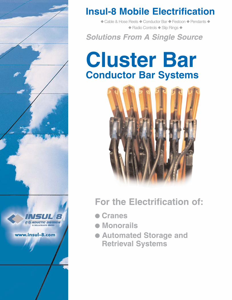
Cluster BarConductor Bar Systems
For the Electrification of:●● Cranes●● Monorails●● Automated Storage and
Retrieval Systems

Page 1(800) 521-4888
Don’t see what you need? Call us!www.insul-8.com
About Insul-8
Information subject to change without notice
Your Single Source for Mobile Electrification
Specifications may change without notice. All products F.O.B. Omaha, NE, or Harlan, IA, unless otherwise specified.
Industrial Electric Reels, Inc., began in 1924 with the founding of Industrial Electric Works (IEW), an electrical contractor based in Omaha, Nebraska. After World War II,IEW began the manufacture of electric cable reeling equipment and started IER as an operating division in 1948.IER’s first cable reel, the hand rewind Series 102 PORT-O-REEL, was quickly followed by light-duty springretractable cable reels. IER pioneered the development ofcable reeling devices and slip rings. Soon the businessexpanded to larger, custom built motor driven reels and custom engineered slip rings. IER’s reputation spread as a quality manufacturer of reels running the gamut from small commercial duty reels to large custom built reels for the mostdemanding applications such as container cranes,stacker/reclaimers and bulk material ship loaders and unloaders.Insul-8 Corporation has been a pioneer in providing safety-covered metal conductor systems for the material handling industry since 1944. Insul-8 was the first company todesign and produce a stainless steel capped aluminum conductor and the only manufacturer of such a product for almost 20 years. Today, there are over 20 millionmeters (nearly 12,500 miles) of Insul-8 contact conductors and tens of thousands of collecting devices throughout the world.Every major port in the United States currently uses Insul-8’s aluminum/stainless steel contact conductors on container cranesdue to the dependability of the bar under the most severe conditions. Insul-8’s festoon systems range from the smallest box-tracksystems to our most rugged Heavy-Duty Festoon. Insul-8’s festoons are known for their safe and efficient operation in which largenumbers of conductors can be handled in minimum space.
Insul-8 has been in the business of supplying power from stationary sources to mobile systems for 60 years. Insul-8’s cable reels,slip rings, conductor bar, festoon systems, pendants and radio controls are used in a wide variety of applications ranging from material handling and mass transit systems to water treatment plants and performing arts theaters.As it has been for the last 60 years and always will be, “conducting” business will continue to be our only business.
Since our inception in 1902, Insul-8 Corporation’s parent company,Delachaux S.A., has been a leading international presence in the business of providing mobile electrification. As the Delachaux arm inNorth and South America, Insul-8 Corporation (formerly sister companies Insul-8 and Industrial Electric Reels, Inc. - a.k.a. IER) carrieson this tradition of innovation and excellence. Insul-8 and IER becamepart of the Delachaux Group in 1975 and officially became one compa-ny on December 31, 1996. Each company has its own rich history.
You’ll find Insul-8 products in use everywhere from irrigation systems and manufacturingplants in the heartland of the United States to public transportation systems in Malaysia.
Insul-8 products can electrify items from small industrial machinery to large
amusement park rides and international public transit systems.
In December 1997, after a nine month endeavor, Insul-8 Corporation became ISO 9001 certified for the design and manufactureof our entire line of mobile electrification products in both of our U.S.A. plants in Omaha, Nebraska, and Harlan, Iowa.
◆ cable and hose reels ◆ conductor bar systems ◆ cable festoon systems ◆◆ slip rings ◆ pendant stations ◆ radio controls ◆
www.insul-8.com

Page 2(800) 521-4888www.insul-8.com
Table of Contents
Don’t see what you need? Call us!Information subject to change without notice
Cluster Bar Components and Definitions....................3Selecting a System........................................................ 5Cluster Bar Components...............................................6Hanger and Anchor Clamps........................................10Brackets........................................................................ 11Collectors......................................................................12Curves and Slip Rings.................................................13Engineering Data..........................................................14Special Notes................................................................15
Specifications May Change Without Notice.
Cluster Bar Standard Features
● UL listed and CSA approved● Engineered for a confined space with 3/4” conductor spacing● Captive “V” contact surface for positive tracking of collector shoe● Certified to International Protection, IP2, standards● Available with crimped or bolted connections● Insulated PVC covering rated at 160O F● Fast and easy to install● Easy to maintain● Operates in lateral or vertical mount using the same components● Operational speeds through 600 fpm● Easily curved in both the horizontal and vertical planes

Page 3(800) 521-4888
Don’t see what you need? Call us!www.insul-8.com
Cluster Bar Components
Information subject to change without notice
Cluster Bar Typical 4 Conductor System
A Conductor Section 15 foot length.......................................................................See Page 5
B Expansion Section 6 foot length.........................................................................See Page 5
C Powerfeed...........................................................................................................See Page 5
D Splice Joints........................................................................................................See Page 7
E Hanger Clamp.....................................................................................................See Page 9
F Multi Conductor Brackets....................................................................................See Page 9
G Anchor Clamp...................................................................................................Seep Page 9
H End Cover...........................................................................................................See Page 6
I Isolation Section.................................................................................................See Page 8
J Collector (Not Shown).......................................................................................See Page 11
K Collector Mounting Staff (Not Shown)..............................................................See Page 11

Page 4(800) 521-4888www.insul-8.com
Selecting the Correct System
Don’t see what you need? Call us!Information subject to change without notice
Selecting a System is Simple
To assist you in selecting a Cluster Bar system, answer the following questions.Return via fax and we’ll provide a quote and qualified customer support.
1. Type of system (Runway, Bridge, Monorail, Other) ______________________
2. Length of System (Ft.) ___________
3. Number of Conductors ___________
4. Number of Vehicles (cranes, etc.) ____________
5. Voltage ______ AC ______ DC
6. Amperage requirement of each vehicle ____________ (pg. 14)
7. Total ampacity required ____________ (pg. 14)
8. Ambient temperature: (if other than -10OF. to +160OF.) ______ to ______
9. Atmosphere: Dry______ Dusty ______ Dirty ______
Corrosive ______ Nuclear ______ Other _______________
10. Bracket Required: Number ______ Web ______ Flange ______
11. Special Concerns: _______________________________________________
Need Assistance?Contact Insul-8 or your Local Representative Now!
We’ll be happy to quote your systemor parts requirements for you.
Page 5(800) 521-4888
Don’t see what you need? Call us!www.insul-8.com
Cluster Bar Components
Information subject to change without notice
Conductor Bar
Expansion Section
Powerfeed
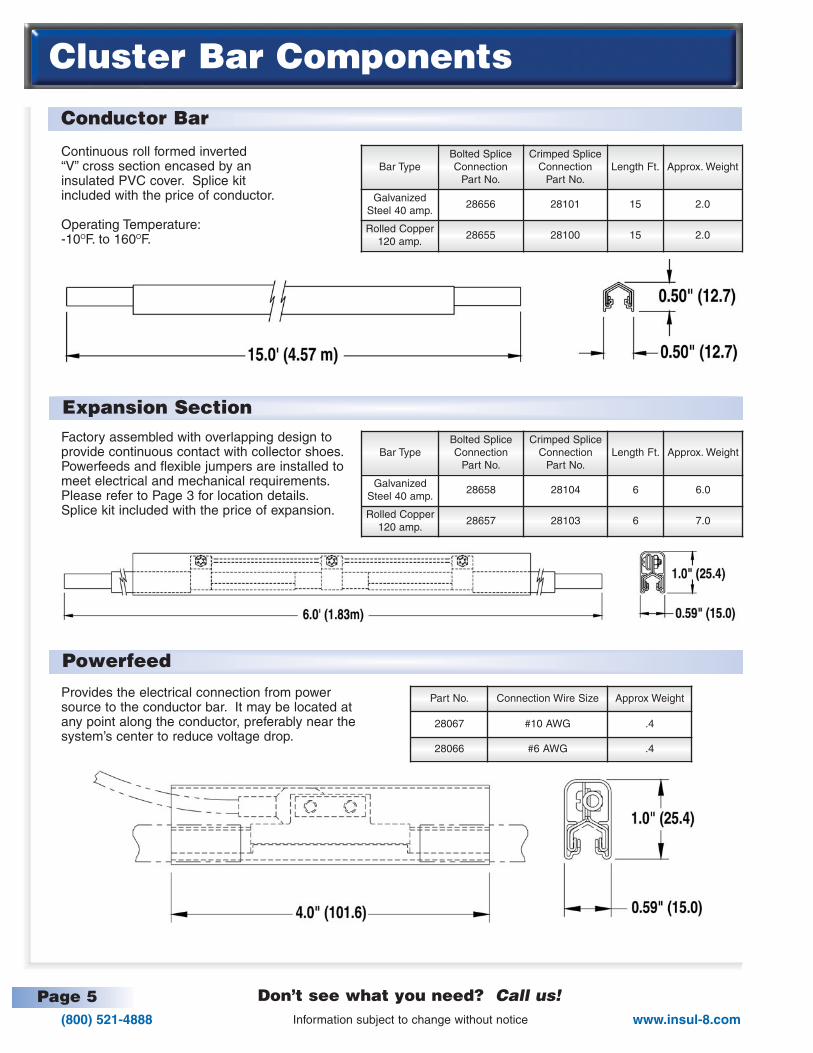
Continuous roll formed inverted“V” cross section encased by aninsulated PVC cover. Splice kitincluded with the price of conductor.
Operating Temperature:-10OF. to 160OF.
Bar TypeBolted SpliceConnection
Part No.
Crimped SpliceConnection
Part No.Length Ft. Approx. Weight
GalvanizedSteel 40 amp.
28656 28101 15 2.0
Rolled Copper120 amp.
28655 28100 15 2.0
Factory assembled with overlapping design to provide continuous contact with collector shoes.Powerfeeds and flexible jumpers are installed tomeet electrical and mechanical requirements.Please refer to Page 3 for location details.Splice kit included with the price of expansion.
Provides the electrical connection from powersource to the conductor bar. It may be located atany point along the conductor, preferably near thesystem’s center to reduce voltage drop.
Bar TypeBolted SpliceConnection
Part No.
Crimped SpliceConnection
Part No.Length Ft. Approx. Weight
GalvanizedSteel 40 amp.
28658 28104 6 6.0
Rolled Copper120 amp.
28657 28103 6 7.0
Part No. Connection Wire Size Approx Weight
28067 #10 AWG .4
28066 #6 AWG .4
Page 6(800) 521-4888www.insul-8.com
Cluster Bar Components
Don’t see what you need? Call us!Information subject to change without notice
End Power Transfer
End Cover
Crimping Tool
Splice Cover Kit
Part No. Connection Wire Size Approx Weight
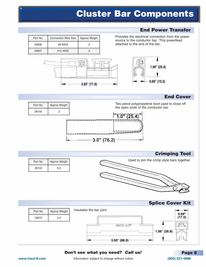
29836 #8 AWG .2
29837 #10 AWG .2
Provides the electrical connection from the powersource to the conductor bar. This powerfeedattaches to the end of the bar.
Two piece polypropylene boot used to close offthe open ends of the conductor bar.
Used to join the crimp style bars together.
Insulates the bar joint.
Part No. Approx Weight
28105 .3
Part No. Approx Weight
28102 5.0
Part No. Approx Weight
29875 5.0

Connects two sections of conductors together
Used to guide the contact shoe through a 1/4” maximum air gap.
Scoop located at the end of the conductor. Designed to gather the collectorsand align them to ride on the conductor bars for discontinuous operation.Consult factory for proper selection.
Page 7(800) 521-4888
Don’t see what you need? Call us!www.insul-8.com
Cluster Bar Components
Information subject to change without notice
Splice Kits
Transfer Cap
Pick-Up Guides
Isolation Sections
Bar TypeBolted SpliceConnection
Part No.
Crimped SpliceConnection
Part No.Approx. Weight
GalvanizedSteel 40 amp.
29632 30211 .20
Rolled Copper120 amp.
29548 30210 .20
Bar TypeBolted SpliceConnection
Part No.
Crimped SpliceConnection
Part No.Length Ft. Approx. Weight
GalvanizedSteel 40 amp.
29833 29935 6 2.0
Rolled Copper120 amp.
29832 29936 6 3.0
Part No. No. Cond. “W” Approx. Wt.
29413 1 .60 .10
28807 3 1.80 .30
28808 4 2.40 .40
28809 5 3.00 .50
28810 6 3.60 .60
Manufactured for electrical separation withinthe electrification system. These sectionsare factory assembled with transfer capsand mechanically aligned brackets to effortlessly guide the contact shoe throughair gaps. Power clamps are part of the 6-foot section enabling a separate electricalconnection. Splice kits included with thepiece of isolation.
Part No. No. Cond
30656 2
34808 3
28127 4
Page 8(800) 521-4888www.insul-8.com
Cluster Bar Components
Don’t see what you need? Call us!Information subject to change without notice
Isolation Kit
Power Interrupting Sections
Take Up Sections
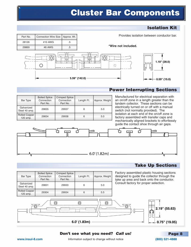
Provides isolation between conductor bar.
*Wire not included.
Part No. Connection Wire Size Approx. Wt.
28126 #10 AWG .5
29869 #8 AWG .5
Bar TypeBolted SpliceConnection
Part No.
Crimped SpliceConnection
Part No.Length Ft. Approx. Weight
GalvanizedSteel 40 amp.
29835 29937 6 5.0
Rolled Copper120 amp.
29834 29938 6 5.0
Bar TypeBolted SpliceConnection
Part No.
Crimped SpliceConnection
Part No.Length Ft. Approx. Weight
GalvanizedSteel 40 amp.
29831 29933 6 5.0
Rolled Copper120 amp.
29304 29934 6 5.5
Manufactured for electrical separation withan on/off zone in a length greater than thetandem collector. These sections can beelectrically turned on or off with a manualswitch (not normally provided). The isolation at each end of the on/off zone isfactory assembled with transfer caps andmechanically aligned brackets to effortlesslyguide the contact shoe through air gaps.
Factory assembled plastic housing sectionsdesigned to guide the collector through thetake up area and back onto the conductor.Consult factory for proper selection.
Page 9(800) 521-4888
Don’t see what you need? Call us!www.insul-8.com
Cluster Bar Components
Information subject to change without notice
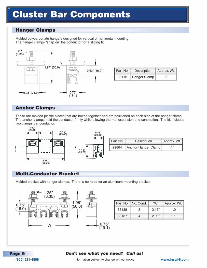
Hanger Clamps
Anchor Clamps
Multi-Conductor Bracket
Molded polycarbonate hangers designed for vertical or horizontal mounting.The hanger clamps “snap on” the conductor for a sliding fit.
These are molded plastic pieces that are bolted together and are positioned on each side of the hanger clamp.The anchor clamps hold the conductor firmly while allowing thermal expansion and contraction. The kit includestwo clamps per conductor.
Molded bracket with hanger clamps. There is no need for an aluminum mounting bracket.
Part No. Description Approx. Wt.
28112 Hanger Clamp .20
Part No. Description Approx. Wt.
29864 Anchor Hanger Clamp .14
Part No. No. Cond. “W” Approx. Wt.
33138 3 2.16” 1.0
33137 4 2.90” 1.1

Page 10(800) 521-4888www.insul-8.com
Cluster Bar Components
Don’t see what you need? Call us!Information subject to change without notice
Multi-Conductor Bracket
Multi-Conductor Web Brackets
Multi-Conductor Flange Bracket
Aluminum mounting channel with hanger clamps, available in various conductor configurations.
Aluminum channel web bracket with assembled hanger clamps in various conductor configurations.
Aluminum channel flange bracket with assembled hangerclamps in various conductor configurations.
(Includes flange clips)
Part No. No. Cond. “W” Approx. Wt.
29475 2 1.50” 0.9
28113 3 2.14” 1.0
28114 4 2.85” 1.1
28115 5 3.56” 1.2
28116 6 4.28” 1.3
28806 7 5.25” 1.4
Part No. No. Cond. “W” Approx. Wt.
28665 3 2.25” 1.4
29939 4 3.00” 1.5
29940 5 3.75” 1.6
29941 6 4.50” 1.6
Part No.No.
Cond.BracketSetting
Approx. Wt.
28666 3 2/1 1.4
29942 4 2/2 1.5
29943 5 2/3 1.6
29944 6 2/4 1.6
29986 3 0/3 1.4
29987 4 0/4 1.6
29988 5 0/5 1.7
29989 6 0/6 1.8
W

Page 11(800) 521-4888
Don’t see what you need? Call us!www.insul-8.com
Collectors
Information subject to change without notice
30 Amp. Collector, Single Conductor
30 Amp. Collector, Multi-Conductor
30 Amp. Compression Collector
Staff Collector Mount
1/2” Square Bar Mount Type.Insulated contact head mounted on self centering, spring loaded arm that articulates in both the vertical and horizontal positions. Exposed metal surfaces do not carry current as mounts are grounded. The sliding contacttype confines wear only to the easily replaceable contact shoes. Part #: 28082
Channel Mount TypeInsulated contact heads mounted on self centering spring loaded arm assemblies that articulate in both the vertical and horizontal positions. Exposed metal surface does not carry current as mounts are grounded.The sliding contact type confines wear only to the easily replaceable contact shoes.
Used for mounting 31589 collector.
Part No. Description Approx. Wt.
32180 14mm, compressioncollector 1.6
Part No. Approx. Wt.
39618C 1.0
Part No. No. Cond “W” Approx. Wt.
31799 2 1.50” 2.5
31583 3 2.25” 3.0
31584 4 3.00” 3.8
31585 5 3.75” 4.6
31586 6 4.50” 5.4
Part No. Description Approx. Wt.
31589 Single Pole Collector .80
Page 12(800) 521-4888www.insul-8.com
Curves & Slip Rings
Don’t see what you need? Call us!Information subject to change without notice
Curves
Curving Machine
Slip Rings
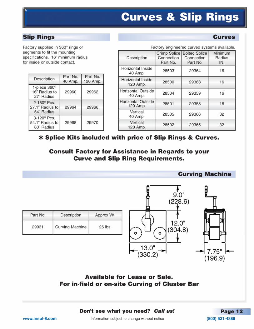
✱ Splice Kits included with price of Slip Rings & Curves.
Consult Factory for Assistance in Regards to yourCurve and Slip Ring Requirements.
Available for Lease or Sale.For in-field or on-site Curving of Cluster Bar
Factory engineered curved systems available.Factory supplied in 360O rings orsegments to fit the mountingspecifications. 16” minimum radius for inside or outside contact.
DescriptionCrimp SpliceConnection
Part No.
Bolted SpliceConnection
Part No.
MinimumRadius
IN.
Horizontal Inside40 Amp. 28503 29364 16
Horizontal Inside120 Amp. 28500 29363 16
Horizontal Outside40 Amp. 28504 29359 16
Horizontal Outside120 Amp. 28501 29358 16
Vertical40 Amp. 28505 29366 32
Vertical120 Amp. 28502 29365 32
Description Part No.40 Amp.
Part No.120 Amp.
1-piece 360O
16” Radius to27” Radius
29960 29962
2-180O Pcs.27.1” Radius to
54” Radius29964 29966
3-120O Pcs.54.1” Radius to
80” Radius29968 29970
Part No. Description Approx Wt.
29931 Curving Machine 25 lbs.
Page 13(800) 521-4888
Don’t see what you need? Call us!www.insul-8.com
Engineering Data
Information subject to change without notice
Proper Selection
Proper selection of Cluster Bar contact conductor systems is simple, requiring only the ampacity, voltage andambient conditions.The method of determining the rating for cranes and hoist is completely outlined in NEC 610-14(e). Further references to the Code are made where applicable.
1. For single crane, simply use the name plate full load ampere rating of the largest motor or group of motors forany one function plus half the rating of the next largest motor or motor groups.
Hoist = 65a x 1.0 = 65.0Bridge = 27a x 0.5 = 13.5
Total 78.5 amps.
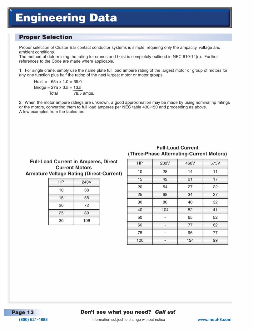
2. When the motor ampere ratings are unknown, a good approximation may be made by using nominal hp ratingsor the motors, converting them to full load amperes per NEC table 430-150 and proceeding as above.A few examples from the tables are:
HP 240V
10 38
15 55
20 72
25 89
30 106
HP 230V 460V 575V
10 28 14 11
15 42 21 17
20 54 27 22
25 68 34 27
30 80 40 32
40 104 52 41
50 - 65 52
60 - 77 62
75 - 96 77
100 - 124 99
Full-Load Current in Amperes, DirectCurrent Motors
Armature Voltage Rating (Direct-Current)
Full-Load Current(Three-Phase Alternating-Current Motors)
Page 14(800) 521-4888www.insul-8.com
Engineering Data
Don’t see what you need? Call us!Information subject to change without notice
How to Figure Voltage Drop
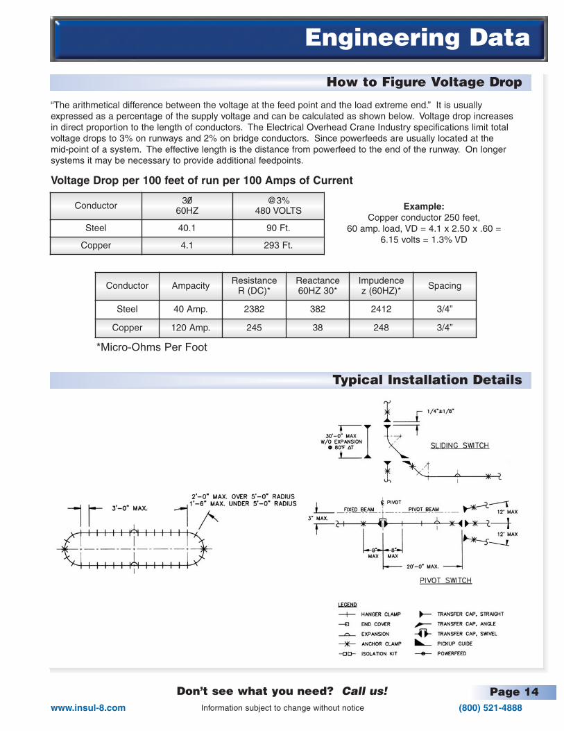
Typical Installation Details
“The arithmetical difference between the voltage at the feed point and the load extreme end.” It is usuallyexpressed as a percentage of the supply voltage and can be calculated as shown below. Voltage drop increasesin direct proportion to the length of conductors. The Electrical Overhead Crane Industry specifications limit totalvoltage drops to 3% on runways and 2% on bridge conductors. Since powerfeeds are usually located at the mid-point of a system. The effective length is the distance from powerfeed to the end of the runway. On longersystems it may be necessary to provide additional feedpoints.
Voltage Drop per 100 feet of run per 100 Amps of Current
Conductor 3060HZ
@3%480 VOLTS
Steel 40.1 90 Ft.
Copper 4.1 293 Ft.
Example:Copper conductor 250 feet,
60 amp. load, VD = 4.1 x 2.50 x .60 =6.15 volts = 1.3% VD
Conductor Ampacity ResistanceR (DC)*
Reactance 60HZ 30*
Impudencez (60HZ)* Spacing
Steel 40 Amp. 2382 382 2412 3/4”
Copper 120 Amp. 245 38 248 3/4”
*Micro-Ohms Per Foot

CANADA175 Boulevard J.F. Kennedy
St. Jerome, Quebec J7Y 4B5
Phone: (514) 565-9900Toll Free: (800) 667-2487
Fax: (514) 432-6985e-mail: [email protected]
MEXICOPuerto La Paz #123 Col. La FE,
San Nicolas de los Garza, N.L. C.P. 66477
Phone: (81) 1090-9013Fax: (81) 1090-9014
e-mail:
USA10102 F Street Omaha, NE 68127
Phone: (402) 339-9300 Toll Free: (800) 521-4888Fax: (402) 339-9627 Toll Free: (800) 780-8329
e-mail: [email protected]
AUSTRALIA:14 England StreetDandenong, Victoria 3175Phone: (3) 9706 88 44Fax: (3) 794 92 98e-mail: [email protected]
CAT8002.1 MN
Distributed By:
SPRING DRIVENREELS
CONDUCTOR BAR FESTOON
SLIP RINGS
CONDUCTOR BAR
MOTOR DRIVENREELS
Please visit our website at:www.insul-8.com
ISO 9001 Certified