configuração inicial hit7300
DESCRIPTION
Documento que facilita o acesso das informações sobre configuração do equipamento.TRANSCRIPT

SURPASS hiT 73004.30
Operating Manual (OMN)
A42022-L5972-E070-02-7619
Issue: 2 Issue date: September 2010

2 A42022-L5972-E070-02-7619Issue: 2 Issue date: September 2010
Operating Manual (OMN)
The information in this document is subject to change without notice and describes only the product defined in the introduction of this documentation. This documentation is intended for the use of Nokia Siemens Networks customers only for the purposes of the agreement under which the document is submitted, and no part of it may be used, reproduced, modified or transmitted in any form or means without the prior written permission of Nokia Siemens Networks. The documentation has been prepared to be used by professional and properly trained personnel, and the customer assumes full responsibility when using it. Nokia Siemens Networks welcomes customer comments as part of the process of continuous development and improvement of the documentation.
The information or statements given in this documentation concerning the suitability, capacity, or performance of the mentioned hardware or software products are given "as is" and all liability arising in connection with such hardware or software products shall be defined conclusively and finally in a separate agreement between Nokia Siemens Networks and the customer. However, Nokia Siemens Networks has made all reasonable efforts to ensure that the instructions contained in the document are adequate and free of material errors and omissions. Nokia Siemens Networks will, if deemed necessary by Nokia Siemens Networks, explain issues which may not be covered by the document.
Nokia Siemens Networks will correct errors in this documentation as soon as possible. IN NO EVENT WILL NOKIA SIEMENS NETWORKS BE LIABLE FOR ERRORS IN THIS DOCUMEN-TATION OR FOR ANY DAMAGES, INCLUDING BUT NOT LIMITED TO SPECIAL, DIRECT, INDIRECT, INCIDENTAL OR CONSEQUENTIAL OR ANY LOSSES, SUCH AS BUT NOT LIMITED TO LOSS OF PROFIT, REVENUE, BUSINESS INTERRUPTION, BUSINESS OPPORTUNITY OR DATA,THAT MAY ARISE FROM THE USE OF THIS DOCUMENT OR THE INFORMATION IN IT.
This documentation and the product it describes are considered protected by copyrights and other intellectual property rights according to the applicable laws.
The wave logo is a trademark of Nokia Siemens Networks Oy. Nokia is a registered trademark of Nokia Corporation. Siemens is a registered trademark of Siemens AG.
Other product names mentioned in this document may be trademarks of their respective owners, and they are mentioned for identification purposes only.
Copyright © Nokia Siemens Networks 2010. All rights reserved.
f Important Notice on Product SafetyElevated voltages are inevitably present at specific points in this electrical equipment. Some of the parts may also have elevated operating temperatures.
Non-observance of these conditions and the safety instructions can result in personal injury or in property damage.
Therefore, only trained and qualified personnel may install and maintain the system.
The system complies with the standard EN 60950 / IEC 60950. All equipment connected has to comply with the applicable safety standards.
The same text in German:
Wichtiger Hinweis zur Produktsicherheit
In elektrischen Anlagen stehen zwangsläufig bestimmte Teile der Geräte unter Span-nung. Einige Teile können auch eine hohe Betriebstemperatur aufweisen.
Eine Nichtbeachtung dieser Situation und der Warnungshinweise kann zu Körperverlet-zungen und Sachschäden führen.
Deshalb wird vorausgesetzt, dass nur geschultes und qualifiziertes Personal die Anlagen installiert und wartet.
Das System entspricht den Anforderungen der EN 60950 / IEC 60950. Angeschlossene Geräte müssen die zutreffenden Sicherheitsbestimmungen erfüllen.

A42022-L5972-E070-02-7619Issue: 2 Issue date: September 2010
3
Operating Manual (OMN)
Table of ContentsThis document has 283 pages.
1 Preface . . . . . . . . . . . . . . . . . . . . . . . . . . . . . . . . . . . . . . . . . . . . . . . . . 131.1 Intended audience . . . . . . . . . . . . . . . . . . . . . . . . . . . . . . . . . . . . . . . . . 131.2 Structure of this document . . . . . . . . . . . . . . . . . . . . . . . . . . . . . . . . . . . 131.3 Symbols and conventions . . . . . . . . . . . . . . . . . . . . . . . . . . . . . . . . . . . 141.4 History of changes . . . . . . . . . . . . . . . . . . . . . . . . . . . . . . . . . . . . . . . . . 151.5 Prerequisites . . . . . . . . . . . . . . . . . . . . . . . . . . . . . . . . . . . . . . . . . . . . . 15
2 Getting started . . . . . . . . . . . . . . . . . . . . . . . . . . . . . . . . . . . . . . . . . . . . 172.1 Working with the GUI . . . . . . . . . . . . . . . . . . . . . . . . . . . . . . . . . . . . . . . 172.1.1 Using the mouse . . . . . . . . . . . . . . . . . . . . . . . . . . . . . . . . . . . . . . . . . . 172.1.2 Using the keyboard . . . . . . . . . . . . . . . . . . . . . . . . . . . . . . . . . . . . . . . . 172.2 Establishing connection to an NE . . . . . . . . . . . . . . . . . . . . . . . . . . . . . 182.2.1 Connecting to an NE on site . . . . . . . . . . . . . . . . . . . . . . . . . . . . . . . . . 182.2.2 Connecting to a remote NE via @CT . . . . . . . . . . . . . . . . . . . . . . . . . . 192.2.3 Connecting to an NE via TNMS CT . . . . . . . . . . . . . . . . . . . . . . . . . . . . 202.2.4 Connecting to an NE via TNMS Core/CDM. . . . . . . . . . . . . . . . . . . . . . 232.2.5 Connecting to an NE via TL1 . . . . . . . . . . . . . . . . . . . . . . . . . . . . . . . . . 262.3 Graphical User Interface . . . . . . . . . . . . . . . . . . . . . . . . . . . . . . . . . . . . 282.3.1 Main window . . . . . . . . . . . . . . . . . . . . . . . . . . . . . . . . . . . . . . . . . . . . . 282.3.2 Main menu . . . . . . . . . . . . . . . . . . . . . . . . . . . . . . . . . . . . . . . . . . . . . . . 292.3.3 Toolbar. . . . . . . . . . . . . . . . . . . . . . . . . . . . . . . . . . . . . . . . . . . . . . . . . . 362.3.4 Direction tab. . . . . . . . . . . . . . . . . . . . . . . . . . . . . . . . . . . . . . . . . . . . . . 372.3.5 Equipment tab . . . . . . . . . . . . . . . . . . . . . . . . . . . . . . . . . . . . . . . . . . . . 382.3.6 Shelf Equipment . . . . . . . . . . . . . . . . . . . . . . . . . . . . . . . . . . . . . . . . . . 392.3.7 Optical Link Directions . . . . . . . . . . . . . . . . . . . . . . . . . . . . . . . . . . . . . . 402.3.8 Functional View . . . . . . . . . . . . . . . . . . . . . . . . . . . . . . . . . . . . . . . . . . . 412.3.9 Message area . . . . . . . . . . . . . . . . . . . . . . . . . . . . . . . . . . . . . . . . . . . . 412.3.10 Status bar . . . . . . . . . . . . . . . . . . . . . . . . . . . . . . . . . . . . . . . . . . . . . . . 42
3 External interfaces . . . . . . . . . . . . . . . . . . . . . . . . . . . . . . . . . . . . . . . . . 433.1 Configuring Telemetry Interface. . . . . . . . . . . . . . . . . . . . . . . . . . . . . . . 433.1.1 Configuring actors . . . . . . . . . . . . . . . . . . . . . . . . . . . . . . . . . . . . . . . . . 443.1.2 Configuring sensors . . . . . . . . . . . . . . . . . . . . . . . . . . . . . . . . . . . . . . . . 453.1.3 Configuring TIF alarm severity. . . . . . . . . . . . . . . . . . . . . . . . . . . . . . . . 453.2 Configuring Engineering Order Wire . . . . . . . . . . . . . . . . . . . . . . . . . . . 463.2.1 Configuring ring manager . . . . . . . . . . . . . . . . . . . . . . . . . . . . . . . . . . . 463.2.2 Establishing a conference call . . . . . . . . . . . . . . . . . . . . . . . . . . . . . . . . 473.2.3 Establishing a selective call . . . . . . . . . . . . . . . . . . . . . . . . . . . . . . . . . . 483.3 Configuring user channels . . . . . . . . . . . . . . . . . . . . . . . . . . . . . . . . . . . 483.3.1 Configuring user channels via OSC. . . . . . . . . . . . . . . . . . . . . . . . . . . . 503.3.2 Configuring user channels via GCC0. . . . . . . . . . . . . . . . . . . . . . . . . . . 503.4 Card faceplates . . . . . . . . . . . . . . . . . . . . . . . . . . . . . . . . . . . . . . . . . . . 513.4.1 Controller cards . . . . . . . . . . . . . . . . . . . . . . . . . . . . . . . . . . . . . . . . . . . 513.4.2 Other active cards . . . . . . . . . . . . . . . . . . . . . . . . . . . . . . . . . . . . . . . . . 54
4 Operation tasks . . . . . . . . . . . . . . . . . . . . . . . . . . . . . . . . . . . . . . . . . . . 56

4 A42022-L5972-E070-02-7619Issue: 2 Issue date: September 2010
Operating Manual (OMN)
4.1 Performance management . . . . . . . . . . . . . . . . . . . . . . . . . . . . . . . . . . . 564.1.1 Configuring PMP general settings . . . . . . . . . . . . . . . . . . . . . . . . . . . . . 604.1.2 Viewing QoS alarms . . . . . . . . . . . . . . . . . . . . . . . . . . . . . . . . . . . . . . . . 614.1.3 Viewing TCA list . . . . . . . . . . . . . . . . . . . . . . . . . . . . . . . . . . . . . . . . . . . 614.1.4 Configuring PMP thresholds . . . . . . . . . . . . . . . . . . . . . . . . . . . . . . . . . . 614.1.5 Configuring TCM mode. . . . . . . . . . . . . . . . . . . . . . . . . . . . . . . . . . . . . . 624.1.6 Configuring the Trail Trace Identifiers. . . . . . . . . . . . . . . . . . . . . . . . . . . 654.1.7 Changing severity of QoS alarms . . . . . . . . . . . . . . . . . . . . . . . . . . . . . . 684.1.8 Viewing the OPMDC-2 card performance parameters . . . . . . . . . . . . . . 684.1.9 Viewing channel power monitoring performance data . . . . . . . . . . . . . . 704.1.10 Viewing performance data . . . . . . . . . . . . . . . . . . . . . . . . . . . . . . . . . . . 714.1.11 Clearing performance data . . . . . . . . . . . . . . . . . . . . . . . . . . . . . . . . . . . 744.1.12 Suppressing history values that are null . . . . . . . . . . . . . . . . . . . . . . . . . 754.1.13 Configuring the performance monitoring mode. . . . . . . . . . . . . . . . . . . . 764.1.14 Configuring the EM synchronization settings . . . . . . . . . . . . . . . . . . . . . 764.2 Protection management . . . . . . . . . . . . . . . . . . . . . . . . . . . . . . . . . . . . . 764.2.1 Adding a protection group. . . . . . . . . . . . . . . . . . . . . . . . . . . . . . . . . . . . 814.2.2 Deleting a protection group. . . . . . . . . . . . . . . . . . . . . . . . . . . . . . . . . . . 844.2.3 Modifying a protection group. . . . . . . . . . . . . . . . . . . . . . . . . . . . . . . . . . 844.2.4 Upgrading system protection . . . . . . . . . . . . . . . . . . . . . . . . . . . . . . . . . 854.2.5 Viewing protection groups. . . . . . . . . . . . . . . . . . . . . . . . . . . . . . . . . . . . 864.2.6 Viewing protection log. . . . . . . . . . . . . . . . . . . . . . . . . . . . . . . . . . . . . . . 874.3 Connection Management . . . . . . . . . . . . . . . . . . . . . . . . . . . . . . . . . . . . 874.3.1 Configuring Head of Mux Tree . . . . . . . . . . . . . . . . . . . . . . . . . . . . . . . . 884.3.2 Viewing cross connections . . . . . . . . . . . . . . . . . . . . . . . . . . . . . . . . . . . 894.3.3 Configuring cross connections . . . . . . . . . . . . . . . . . . . . . . . . . . . . . . . . 914.3.4 Viewing internal port connections . . . . . . . . . . . . . . . . . . . . . . . . . . . . . . 934.3.5 Configuring internal port connections . . . . . . . . . . . . . . . . . . . . . . . . . . . 934.3.6 Viewing the GFP cross connections . . . . . . . . . . . . . . . . . . . . . . . . . . . . 944.3.7 Configuring GFP cross connections . . . . . . . . . . . . . . . . . . . . . . . . . . . . 954.4 Service provisioning using Enhanced Power Control . . . . . . . . . . . . . . 1024.4.1 Pre-emphasis methods . . . . . . . . . . . . . . . . . . . . . . . . . . . . . . . . . . . . . 1054.4.2 Service provisioning strategy . . . . . . . . . . . . . . . . . . . . . . . . . . . . . . . . 1094.4.2.1 Service provisioning via NCF . . . . . . . . . . . . . . . . . . . . . . . . . . . . . . . . 1164.4.2.2 Service provisioning via NMS . . . . . . . . . . . . . . . . . . . . . . . . . . . . . . . . 1194.4.3 Installing hardware and fiber cabling . . . . . . . . . . . . . . . . . . . . . . . . . . 1254.4.4 Downloading and swapping the new NCF file . . . . . . . . . . . . . . . . . . . 1254.4.5 Configuring optical link control parameters. . . . . . . . . . . . . . . . . . . . . . 1264.4.6 Configuring traffic channel settings. . . . . . . . . . . . . . . . . . . . . . . . . . . . 1274.4.6.1 Configuring traffic channel settings at the head end NE. . . . . . . . . . . . 1284.4.6.2 Configuring traffic channel settings at an intermediate NE . . . . . . . . . . 1294.4.6.3 Configuring traffic channel settings at the tail end NE . . . . . . . . . . . . . 1304.4.7 Configuring Transponder cards . . . . . . . . . . . . . . . . . . . . . . . . . . . . . . 1324.4.8 Configuring channel provision settings . . . . . . . . . . . . . . . . . . . . . . . . . 1334.4.9 Configuring add/drop channel status within the link . . . . . . . . . . . . . . . 1354.4.10 Performing power adjustment . . . . . . . . . . . . . . . . . . . . . . . . . . . . . . . . 1354.4.10.1 Without Measurement. . . . . . . . . . . . . . . . . . . . . . . . . . . . . . . . . . . . . . 135

A42022-L5972-E070-02-7619Issue: 2 Issue date: September 2010
5
Operating Manual (OMN)
4.4.10.2 With measurement using an OSA . . . . . . . . . . . . . . . . . . . . . . . . . . . . 1364.4.10.3 With measurement using an F40MR-1 card . . . . . . . . . . . . . . . . . . . . 1384.4.10.4 With measurement using an MCP4xx-x card. . . . . . . . . . . . . . . . . . . . 1384.4.11 Optimizing the pre-emphasis section. . . . . . . . . . . . . . . . . . . . . . . . . . 1394.4.12 Adjusting add channels . . . . . . . . . . . . . . . . . . . . . . . . . . . . . . . . . . . . 1414.4.12.1 For ONN-I/R/R2/RT/T/X or ONN-I80/R80/RT80/T80/X80 NEs . . . . . . 1414.4.12.2 For ONN-S . . . . . . . . . . . . . . . . . . . . . . . . . . . . . . . . . . . . . . . . . . . . . . 1434.4.13 Updating the channel count . . . . . . . . . . . . . . . . . . . . . . . . . . . . . . . . . 1444.4.14 Adjusting drop channels . . . . . . . . . . . . . . . . . . . . . . . . . . . . . . . . . . . 1454.4.15 Setting power reference values . . . . . . . . . . . . . . . . . . . . . . . . . . . . . . 1464.4.16 Adjusting monitoring port loss . . . . . . . . . . . . . . . . . . . . . . . . . . . . . . . 1474.4.17 Performing a link section shutdown . . . . . . . . . . . . . . . . . . . . . . . . . . . 1474.4.18 Removing a link section . . . . . . . . . . . . . . . . . . . . . . . . . . . . . . . . . . . . 148
5 Maintenance tasks. . . . . . . . . . . . . . . . . . . . . . . . . . . . . . . . . . . . . . . . 1495.1 Fault management . . . . . . . . . . . . . . . . . . . . . . . . . . . . . . . . . . . . . . . . 1495.1.1 Viewing alarms . . . . . . . . . . . . . . . . . . . . . . . . . . . . . . . . . . . . . . . . . . 1495.1.2 Viewing alarm log . . . . . . . . . . . . . . . . . . . . . . . . . . . . . . . . . . . . . . . . 1505.1.3 Suppressing alarm notifications . . . . . . . . . . . . . . . . . . . . . . . . . . . . . . 1515.1.4 Changing the severity of alarms . . . . . . . . . . . . . . . . . . . . . . . . . . . . . 1525.1.5 Configuring the alarm severity level. . . . . . . . . . . . . . . . . . . . . . . . . . . 1525.1.6 Changing alarm persistency . . . . . . . . . . . . . . . . . . . . . . . . . . . . . . . . 1535.2 Activating remote loops . . . . . . . . . . . . . . . . . . . . . . . . . . . . . . . . . . . . 1545.3 Replacing shelf air filter . . . . . . . . . . . . . . . . . . . . . . . . . . . . . . . . . . . . 1555.4 Configuring air filter maintenance settings. . . . . . . . . . . . . . . . . . . . . . 1555.5 Performing a link section recovery. . . . . . . . . . . . . . . . . . . . . . . . . . . . 157
6 Administration tasks. . . . . . . . . . . . . . . . . . . . . . . . . . . . . . . . . . . . . . . 1616.1 DCN management . . . . . . . . . . . . . . . . . . . . . . . . . . . . . . . . . . . . . . . . 1616.1.1 Configuring DCN via GCC0 . . . . . . . . . . . . . . . . . . . . . . . . . . . . . . . . . 1636.1.2 Configuring gateway function . . . . . . . . . . . . . . . . . . . . . . . . . . . . . . . 1646.1.3 Configuring DHCP settings . . . . . . . . . . . . . . . . . . . . . . . . . . . . . . . . . 1676.1.4 Splitting a DCN domain . . . . . . . . . . . . . . . . . . . . . . . . . . . . . . . . . . . . 1696.1.5 Merging DCN domains. . . . . . . . . . . . . . . . . . . . . . . . . . . . . . . . . . . . . 1726.1.6 Configuring STP . . . . . . . . . . . . . . . . . . . . . . . . . . . . . . . . . . . . . . . . . 1756.1.7 Configuring Q and QF interfaces . . . . . . . . . . . . . . . . . . . . . . . . . . . . . 1786.1.8 Configuring static routes . . . . . . . . . . . . . . . . . . . . . . . . . . . . . . . . . . . 1816.1.9 Configuring reachable systems . . . . . . . . . . . . . . . . . . . . . . . . . . . . . . 1836.1.10 Viewing SNMP trap forwarding entries . . . . . . . . . . . . . . . . . . . . . . . . 1846.1.11 Viewing DCN diagnostic data . . . . . . . . . . . . . . . . . . . . . . . . . . . . . . . 1846.2 Configuration management . . . . . . . . . . . . . . . . . . . . . . . . . . . . . . . . . 1856.2.1 Adding and removing shelves . . . . . . . . . . . . . . . . . . . . . . . . . . . . . . . 1856.2.2 Adding and removing cards . . . . . . . . . . . . . . . . . . . . . . . . . . . . . . . . . 1876.2.3 Changing NE state. . . . . . . . . . . . . . . . . . . . . . . . . . . . . . . . . . . . . . . . 1906.2.4 Configuring shelf ID display mode . . . . . . . . . . . . . . . . . . . . . . . . . . . . 1906.2.5 Configuring shelf location . . . . . . . . . . . . . . . . . . . . . . . . . . . . . . . . . . 1916.2.6 Setting card user label . . . . . . . . . . . . . . . . . . . . . . . . . . . . . . . . . . . . . 1926.2.7 Setting card line direction . . . . . . . . . . . . . . . . . . . . . . . . . . . . . . . . . . 192

6 A42022-L5972-E070-02-7619Issue: 2 Issue date: September 2010
Operating Manual (OMN)
6.2.8 Viewing NE/card diagnostic data . . . . . . . . . . . . . . . . . . . . . . . . . . . . . 1936.2.9 Viewing transponder card Port Labels information . . . . . . . . . . . . . . . . 1936.2.10 Viewing/Configuring administrative states . . . . . . . . . . . . . . . . . . . . . . 1946.2.11 Viewing operational state . . . . . . . . . . . . . . . . . . . . . . . . . . . . . . . . . . . 1956.2.12 Viewing hardware inventory data . . . . . . . . . . . . . . . . . . . . . . . . . . . . . 1966.2.13 Viewing the port list of a card . . . . . . . . . . . . . . . . . . . . . . . . . . . . . . . . 1976.2.14 Resetting the NE to default configuration . . . . . . . . . . . . . . . . . . . . . . . 1976.2.15 Resetting/Rebooting cards . . . . . . . . . . . . . . . . . . . . . . . . . . . . . . . . . . 1976.2.16 Configuring NTP and NE time. . . . . . . . . . . . . . . . . . . . . . . . . . . . . . . . 1986.2.17 Configuring client mode . . . . . . . . . . . . . . . . . . . . . . . . . . . . . . . . . . . . 2006.2.18 Configuring the optical channel. . . . . . . . . . . . . . . . . . . . . . . . . . . . . . . 2006.2.19 Configuring the client interface . . . . . . . . . . . . . . . . . . . . . . . . . . . . . . . 2036.2.20 Configuring the LOS functions . . . . . . . . . . . . . . . . . . . . . . . . . . . . . . . 2046.2.21 Selecting the AIS operation mode . . . . . . . . . . . . . . . . . . . . . . . . . . . . 2056.2.22 Configuring the ALS function . . . . . . . . . . . . . . . . . . . . . . . . . . . . . . . . 2066.2.23 Configuring the payload type . . . . . . . . . . . . . . . . . . . . . . . . . . . . . . . . 2086.2.24 Configuring the UPI. . . . . . . . . . . . . . . . . . . . . . . . . . . . . . . . . . . . . . . . 2106.2.25 Configuring client and line lasers . . . . . . . . . . . . . . . . . . . . . . . . . . . . . 2116.2.26 Configuring GMPLS control plane . . . . . . . . . . . . . . . . . . . . . . . . . . . . 2126.2.27 Configuring VOA settings . . . . . . . . . . . . . . . . . . . . . . . . . . . . . . . . . . . 2126.2.28 Configuring an OPMDC-2 card . . . . . . . . . . . . . . . . . . . . . . . . . . . . . . . 2136.2.29 Configuring channel power thresholds . . . . . . . . . . . . . . . . . . . . . . . . . 2146.2.30 Configuring a CFSU-1 card. . . . . . . . . . . . . . . . . . . . . . . . . . . . . . . . . . 2156.2.31 Configuring the I04TQ10G-1 port role . . . . . . . . . . . . . . . . . . . . . . . . . 2166.2.32 Launching the I22CE10G-1 console . . . . . . . . . . . . . . . . . . . . . . . . . . . 2166.2.33 Configuring the O02CSP-1 LOS threshold . . . . . . . . . . . . . . . . . . . . . . 2176.2.34 Configuring supervision mode . . . . . . . . . . . . . . . . . . . . . . . . . . . . . . . 2176.2.35 Viewing logs . . . . . . . . . . . . . . . . . . . . . . . . . . . . . . . . . . . . . . . . . . . . . 2186.2.36 Clearing logs . . . . . . . . . . . . . . . . . . . . . . . . . . . . . . . . . . . . . . . . . . . . . 2206.3 L2 card configuration management . . . . . . . . . . . . . . . . . . . . . . . . . . . 2206.3.1 Link Aggregation Group (LAG) provisioning . . . . . . . . . . . . . . . . . . . . . 2206.3.2 Metro Ethernet service provisioning . . . . . . . . . . . . . . . . . . . . . . . . . . . 2226.3.3 Configuring L2 protocol tunneling . . . . . . . . . . . . . . . . . . . . . . . . . . . . . 2326.3.4 Configuring MSTP. . . . . . . . . . . . . . . . . . . . . . . . . . . . . . . . . . . . . . . . . 2336.3.5 QoS configuration . . . . . . . . . . . . . . . . . . . . . . . . . . . . . . . . . . . . . . . . . 2356.4 Software management . . . . . . . . . . . . . . . . . . . . . . . . . . . . . . . . . . . . . 2376.4.1 Uploading/Downloading a MIB . . . . . . . . . . . . . . . . . . . . . . . . . . . . . . . 2376.4.1.1 How to upload the MIB contents . . . . . . . . . . . . . . . . . . . . . . . . . . . . . . 2386.4.1.2 How to download and activate a MIB file . . . . . . . . . . . . . . . . . . . . . . . 2396.4.2 Verifying the active/inactive APS version . . . . . . . . . . . . . . . . . . . . . . . 2406.4.3 Uploading the APS record . . . . . . . . . . . . . . . . . . . . . . . . . . . . . . . . . . 2406.4.4 Copying an APS to the inactive bank . . . . . . . . . . . . . . . . . . . . . . . . . . 2416.4.5 Downloading and swapping an APS. . . . . . . . . . . . . . . . . . . . . . . . . . . 2416.4.6 Downloading, uploading and swapping a TransNet Archive. . . . . . . . . 2436.4.7 Downloading, uploading, and swapping an NCF . . . . . . . . . . . . . . . . . 2456.4.8 Distributing and swapping NCFs via TransNet archive. . . . . . . . . . . . . 2476.5 Security management . . . . . . . . . . . . . . . . . . . . . . . . . . . . . . . . . . . . . . 250

A42022-L5972-E070-02-7619Issue: 2 Issue date: September 2010
7
Operating Manual (OMN)
6.5.1 Creating user accounts . . . . . . . . . . . . . . . . . . . . . . . . . . . . . . . . . . . . 2506.5.2 Deleting user accounts . . . . . . . . . . . . . . . . . . . . . . . . . . . . . . . . . . . . 2506.5.3 Changing passwords . . . . . . . . . . . . . . . . . . . . . . . . . . . . . . . . . . . . . . 2516.5.4 Resetting user password . . . . . . . . . . . . . . . . . . . . . . . . . . . . . . . . . . . 2526.5.5 Configuring user details . . . . . . . . . . . . . . . . . . . . . . . . . . . . . . . . . . . . 2526.5.6 Configuring user sessions . . . . . . . . . . . . . . . . . . . . . . . . . . . . . . . . . . 2556.5.7 Configuring login warning message. . . . . . . . . . . . . . . . . . . . . . . . . . . 2566.5.8 Viewing security log . . . . . . . . . . . . . . . . . . . . . . . . . . . . . . . . . . . . . . . 2576.5.9 Configuring shelves security . . . . . . . . . . . . . . . . . . . . . . . . . . . . . . . . 258
7 Appendix: OSA requirements and measurements. . . . . . . . . . . . . . . . 2597.1 OSA instrument requirements . . . . . . . . . . . . . . . . . . . . . . . . . . . . . . . 2597.2 Parameter settings for spectrum measurement. . . . . . . . . . . . . . . . . . 2607.3 Acceptance threshold for valid channels . . . . . . . . . . . . . . . . . . . . . . . 2607.4 Calibration . . . . . . . . . . . . . . . . . . . . . . . . . . . . . . . . . . . . . . . . . . . . . . 2617.5 Measurement setup . . . . . . . . . . . . . . . . . . . . . . . . . . . . . . . . . . . . . . . 2617.5.1 Power adjustment with measurement using an OSA. . . . . . . . . . . . . . 2617.5.2 Optimizing the pre-emphasis section - manual . . . . . . . . . . . . . . . . . . 2617.6 File format for OSA measurements . . . . . . . . . . . . . . . . . . . . . . . . . . . 261
8 Appendix: OTS protection via O02CSP-1 card . . . . . . . . . . . . . . . . . . 263
9 Glossary. . . . . . . . . . . . . . . . . . . . . . . . . . . . . . . . . . . . . . . . . . . . . . . . 266
10 Abbreviations . . . . . . . . . . . . . . . . . . . . . . . . . . . . . . . . . . . . . . . . . . . . 276

8 A42022-L5972-E070-02-7619Issue: 2 Issue date: September 2010
Operating Manual (OMN)
List of FiguresFigure 1 IP sub-networks in a TNMS CT management system . . . . . . . . . . . . . . 21Figure 2 IP sub-networks in a TNMS Core/CDM management system . . . . . . . . 24Figure 3 EM main window. . . . . . . . . . . . . . . . . . . . . . . . . . . . . . . . . . . . . . . . . . . 28Figure 4 Main menu . . . . . . . . . . . . . . . . . . . . . . . . . . . . . . . . . . . . . . . . . . . . . . . 29Figure 5 Direction tab window. . . . . . . . . . . . . . . . . . . . . . . . . . . . . . . . . . . . . . . . 38Figure 6 Equipment tab window . . . . . . . . . . . . . . . . . . . . . . . . . . . . . . . . . . . . . . 39Figure 7 Shelf Equipment window of a standard shelf . . . . . . . . . . . . . . . . . . . . . 40Figure 8 Shelf Equipment window of a flatpack shelf . . . . . . . . . . . . . . . . . . . . . . 40Figure 9 OSC Link Directions window. . . . . . . . . . . . . . . . . . . . . . . . . . . . . . . . . . 41Figure 10 Functional view window of an I08T10G-1 transponder card. . . . . . . . . . 41Figure 11 Message area . . . . . . . . . . . . . . . . . . . . . . . . . . . . . . . . . . . . . . . . . . . . . 42Figure 12 Status bar . . . . . . . . . . . . . . . . . . . . . . . . . . . . . . . . . . . . . . . . . . . . . . . . 42Figure 13 Loop-free networks . . . . . . . . . . . . . . . . . . . . . . . . . . . . . . . . . . . . . . . . . 47Figure 14 User channel configuration . . . . . . . . . . . . . . . . . . . . . . . . . . . . . . . . . . . 49Figure 15 TCM levels usage example. . . . . . . . . . . . . . . . . . . . . . . . . . . . . . . . . . . 63Figure 16 Possible slot assignments of OChP in I01T10G-1, I08T10G-1, and
I01T40G-1 cards . . . . . . . . . . . . . . . . . . . . . . . . . . . . . . . . . . . . . . . . . . . 79Figure 17 I05AD10G-1 GFP cross connection types . . . . . . . . . . . . . . . . . . . . . . . 94Figure 18 Spans, link sections and pre-emphasis sections example.. . . . . . . . . . 104Figure 19 Add/Drop channels and Express channels . . . . . . . . . . . . . . . . . . . . . . 104Figure 20 Optical channel upgrade example in a linear configuration . . . . . . . . . 111Figure 21 Optical channel upgrade visit order . . . . . . . . . . . . . . . . . . . . . . . . . . . 111Figure 22 Optical channel downgrade example in a linear configuration . . . . . . . 113Figure 23 Optical channel downgrade visit order . . . . . . . . . . . . . . . . . . . . . . . . . 113Figure 24 Optical channel reconfiguration example in a meshed configuration . . 115Figure 25 Optical channel reconfiguration visit order . . . . . . . . . . . . . . . . . . . . . . 115Figure 26 OSA measurement setup for power adjustment with measurement using
an OSA . . . . . . . . . . . . . . . . . . . . . . . . . . . . . . . . . . . . . . . . . . . . . . . . . 137Figure 27 OSA measurement setup for optimizing the pre-emphasis section - manual
(Tx and Rx measurements) . . . . . . . . . . . . . . . . . . . . . . . . . . . . . . . . . 140Figure 28 OSA measurement setup for adjusting add channels. . . . . . . . . . . . . . 143Figure 29 Link section, without an ONN-S, recovery example . . . . . . . . . . . . . . . 158Figure 30 Link section, without an ONN-S, recovery visit order . . . . . . . . . . . . . . 158Figure 31 Link section, with an ONN-S, recovery example. . . . . . . . . . . . . . . . . . 159Figure 32 Link section, with an ONN-S, recovery visit order. . . . . . . . . . . . . . . . . 159Figure 33 Single DCN domain example . . . . . . . . . . . . . . . . . . . . . . . . . . . . . . . . 162Figure 34 IP sub-networks in TMN system . . . . . . . . . . . . . . . . . . . . . . . . . . . . . . 165Figure 35 DCN domain split example . . . . . . . . . . . . . . . . . . . . . . . . . . . . . . . . . . 170Figure 36 Merge of two domains maintaining the two original DCN domains. . . . 173Figure 37 Merge of two domains to create a single DCN domain. . . . . . . . . . . . . 174Figure 38 STP configuration in a single-domain meshed network . . . . . . . . . . . . 176Figure 39 STP configuration in border-NEs . . . . . . . . . . . . . . . . . . . . . . . . . . . . . 177Figure 40 Static routes in a SURPASS hiT 7300 network . . . . . . . . . . . . . . . . . . 182Figure 41 Meshed network with EPL and EVPL services . . . . . . . . . . . . . . . . . . . 222Figure 42 Ring network with EVPL service . . . . . . . . . . . . . . . . . . . . . . . . . . . . . . 226Figure 43 Network with EVP-LAN service. . . . . . . . . . . . . . . . . . . . . . . . . . . . . . . 230

A42022-L5972-E070-02-7619Issue: 2 Issue date: September 2010
9
Operating Manual (OMN)
Figure 44 MST instances 10 and 20. . . . . . . . . . . . . . . . . . . . . . . . . . . . . . . . . . . 233

10 A42022-L5972-E070-02-7619Issue: 2 Issue date: September 2010
Operating Manual (OMN)
List of TablesTable 1 Structure of the document . . . . . . . . . . . . . . . . . . . . . . . . . . . . . . . . . . . 13Table 2 List of conventions used in this document . . . . . . . . . . . . . . . . . . . . . . . 14Table 3 Document history . . . . . . . . . . . . . . . . . . . . . . . . . . . . . . . . . . . . . . . . . . 15Table 4 EM hardware and software requirements . . . . . . . . . . . . . . . . . . . . . . . 16Table 5 Standard keyboard operations . . . . . . . . . . . . . . . . . . . . . . . . . . . . . . . . 17Table 6 Main menu items . . . . . . . . . . . . . . . . . . . . . . . . . . . . . . . . . . . . . . . . . . 30Table 7 Toolbar icons . . . . . . . . . . . . . . . . . . . . . . . . . . . . . . . . . . . . . . . . . . . . . 36Table 8 Status bar . . . . . . . . . . . . . . . . . . . . . . . . . . . . . . . . . . . . . . . . . . . . . . . . 42Table 9 Summary table for TIF actor states . . . . . . . . . . . . . . . . . . . . . . . . . . . . 44Table 10 Controller card interfaces . . . . . . . . . . . . . . . . . . . . . . . . . . . . . . . . . . . . 52Table 11 Controller card LED behavior during NE start-up . . . . . . . . . . . . . . . . . 54Table 12 Standard LEDs for active cards . . . . . . . . . . . . . . . . . . . . . . . . . . . . . . . 54Table 13 Performance monitoring parameters SDH/SONET/OTUk/ODUk(T) . . . 58Table 14 Performance monitoring parameters GFP . . . . . . . . . . . . . . . . . . . . . . . 59Table 15 Performance monitoring parameters GbE/10GbE . . . . . . . . . . . . . . . . . 59Table 16 Performance monitoring parameters FC/FICON . . . . . . . . . . . . . . . . . . 59Table 17 Combinations of working/protection line ports and client ports on the
I04T2G5-1 card . . . . . . . . . . . . . . . . . . . . . . . . . . . . . . . . . . . . . . . . . . . 77Table 18 Operator switch settings in a protection modification . . . . . . . . . . . . . . . 84Table 19 Available bandwidth for GFP-T mapping on each line interface . . . . . . 96Table 20 Required bandwidth for GFP-T mapping of supported client data types 96Table 21 Precalculated pre-emphasis without measurement method tasks . . . . 106Table 22 Precalculated pre-emphasis with measurement method tasks . . . . . . 107Table 23 Enhanced pre-emphasis - manual method tasks . . . . . . . . . . . . . . . . . 107Table 24 Enhanced pre-emphasis - automated method tasks . . . . . . . . . . . . . . 108Table 25 Delayed enhanced pre-emphasis without measurement method tasks . .
108Table 26 Delayed enhanced pre-emphasis with measurement method tasks . . 109Table 27 Optical channel upgrade tasks for each NE, using the service provisioning
via NCF . . . . . . . . . . . . . . . . . . . . . . . . . . . . . . . . . . . . . . . . . . . . . . . . 116Table 28 Optical channel downgrade tasks for each NE, using the service provision-
ing via NCF . . . . . . . . . . . . . . . . . . . . . . . . . . . . . . . . . . . . . . . . . . . . . 117Table 29 Optical channel reconfiguration tasks for each NE, using the service provi-
sioning via NCF . . . . . . . . . . . . . . . . . . . . . . . . . . . . . . . . . . . . . . . . . . 118Table 30 Optical channel upgrade tasks for each NE, using service provisioning via
NMS . . . . . . . . . . . . . . . . . . . . . . . . . . . . . . . . . . . . . . . . . . . . . . . . . . . 120Table 31 Optical channel downgrade tasks for each NE, using service provisioning
via NMS . . . . . . . . . . . . . . . . . . . . . . . . . . . . . . . . . . . . . . . . . . . . . . . . 122Table 32 Optical channel reconfiguration tasks for each NE, using service provision-
ing via NMS . . . . . . . . . . . . . . . . . . . . . . . . . . . . . . . . . . . . . . . . . . . . . 124Table 33 Remote loops available per cards . . . . . . . . . . . . . . . . . . . . . . . . . . . . 154Table 34 Link section recovery tasks for each NE . . . . . . . . . . . . . . . . . . . . . . . 158Table 35 Link section recovery tasks for each NE . . . . . . . . . . . . . . . . . . . . . . . 159Table 36 NE types roles and capabilities . . . . . . . . . . . . . . . . . . . . . . . . . . . . . . 162Table 37 IP address ranges used within SURPASS hiT 7300 . . . . . . . . . . . . . . 179Table 38 Default Payload type transmitted and the default Payload type expected as
function of the Client mode . . . . . . . . . . . . . . . . . . . . . . . . . . . . . . . . . 208

A42022-L5972-E070-02-7619Issue: 2 Issue date: September 2010
11
Operating Manual (OMN)
Table 39 Default UPI transmitted, UPI expected, UPI OS transmitted and UPI OS ex-pected as function of the Client mode/Mapping mode . . . . . . . . . . . . 210
Table 40 Operator Switch and Switching State numeric correspondence . . . . . 219Table 41 Tunneling actions in the supported service types . . . . . . . . . . . . . . . . 232Table 42 Default user accounts and respective passwords . . . . . . . . . . . . . . . . 250Table 43 OSA specifications . . . . . . . . . . . . . . . . . . . . . . . . . . . . . . . . . . . . . . . 260

12 A42022-L5972-E070-02-7619Issue: 2 Issue date: September 2010
Operating Manual (OMN)

A42022-L5972-E070-02-7619Issue: 2 Issue date: September 2010
13
Operating Manual (OMN) Preface
1 PrefaceThis preface describes the audience, structure, conventions, history of changes and prerequisites of the SURPASS hiT 7300 Operating Manual (OMN).
1.1 Intended audienceThis guide is intended for personnel/network managers responsible for operating, main-taining and administrating the SURPASS hiT 7300 system. This guide assumes that the reader understands basic networking concepts, and has a strong working knowledge of optical systems. Basic computer knowledge, such as using a mouse and the basic Windows functions, is also required.
1.2 Structure of this documentThis document comprises the following main chapters:
☞ Some features described in this documentation set may not be available. In order to identify the features released for the system, please refer to the Release Notes delivered with the product.
Chapter Title Subject
Chapter 1 Preface Provides an introduction and overview of this manual.
Chapter 2 Getting started Describes how to connect to the Network Element (NE), provides an overview of the Element Manager (EM) and general Graphical User Interface (GUI) operating information.
Chapter 3 External interfaces Describes how to use/configure the external interfaces of the NE.
Chapter 4 Operation tasks Describes the tasks within the scope of operating a SURPASS hiT 7300 system.
Chapter 5 Maintenance tasks Describes the tasks within the scope of maintaining a SURPASS hiT 7300 system.
Chapter 6 Administration tasks Describes the tasks within the scope of administrating a SURPASS hiT 7300 system.
Chapter 7 Appendix: OSA requirements and measurements
Detailed description of an Optical Spectrum Analyzer (OSA) setup.
Chapter 8 Glossary List of terms and corresponding defini-tions used in this document.
Chapter 90 Abbreviations Provides a list of the abbreviations used in this manual.
Table 1 Structure of the document

14 A42022-L5972-E070-02-7619Issue: 2 Issue date: September 2010
Operating Manual (OMN)Preface
1.3 Symbols and conventionsThe following symbols and conventions are used in this document:
Representation Meaning
Bold Text in the Graphic User Interface (window and wizard titles, field names, buttons, etc.) is represented in bold face.
Example: Click Shutdown and then click OK to turn off the com-puter.
Italic Field values, file names, file extensions, folder and directory names are denoted by italic text.
Examples: Enter 192.168.0.1 in the IP address field. Click OK to produce a .pdf file.
Courier Command and screen output are denoted by courier font.
Example: ping -t 192.168.0.1
<Angle brackets> Place holders for distinct names or values are represented by enclosing them in <angle brackets>. If a file name is involved, italic text will also be used.
Example: The naming convention for the log files is <NEname>.txt, where <NEname> is the name of the NE sending the messages.
Keyboard button Keyboard keys are represented with a surrounding box.
Example: Press Enter .
[Square brackets] Keyboard shortcuts are represented using square brackets.
Example: Press [CTRL+ALT+DEL] to open the Task Manager.
> The “>” symbol is used as short form to define a path through indi-vidual elements of the Graphic User Interface, e.g., menus and menu commands.
Example: On the Windows taskbar, select Start > Programs > TNMS > Client menu command to start the TNMS Core/CDM Client.
☞ A tip provides additional information related to the topic described.
g A note provides important information on a situation that can cause property damage or data loss.
A note introduced in the text by the keyword NOTICE: describes a hazard that may result in property damage but not in personal injury.
Table 2 List of conventions used in this document

A42022-L5972-E070-02-7619Issue: 2 Issue date: September 2010
15
Operating Manual (OMN) Preface
Screenshots of the Graphic User Interface are examples only to illustrate principles. This especially applies to a software version number visible in a screenshot.
1.4 History of changes
1.5 PrerequisitesIn order to use this manual properly, the following prerequisites must be fulfilled.
User requirementsTo work with a SURPASS hiT 7300 system the user requires the following knowledge: • Electrical, mechanical safety regulations and laser safety precautions as described
in the Safety Instructions document. • Optical system, protocols and specific SURPASS hiT 7300 functions as described
in Technical Description (TED). • Using a mouse/keyboard and the basic Windows functions.
System requirementsThe SURPASS hiT 7300 must be commissioned: • The hardware is installed (racks, shelves and cards) and cabled according to
SURPASS TransNet reports, Interconnect, Configuration and Mechanical Assembly (ICMA) and Installation and Test Manual (ITMN).
• The NEs are commissioned according to the NE commissioning or Stand-alone Optical Node commissioning manuals.
f A safety message provides information on a dangerous situation that could cause bodily injury.
The different hazard levels are introduced in the text by the follow-ing keywords:
DANGER! - Indicates a hazardous situation which, if not avoided, will result in death or serious (irreversible) personal injury.
WARNING! - Indicates a hazardous situation which, if not avoided, could result in death or serious (irreversible) personal injury.
CAUTION! - Indicates a hazardous situation which, if not avoided, may result in minor or moderate (reversible) personal injury.
Representation Meaning
Table 2 List of conventions used in this document (Cont.)
Issue Issue date Remarks
1 June 2010 Initial version
2 September 2010 Maintenance version
Table 3 Document history

16 A42022-L5972-E070-02-7619Issue: 2 Issue date: September 2010
Operating Manual (OMN)Preface
• The optical links are commissioned according to the Optical Link Commissioning (OLC) manual.
Hardware and software requirementsTable 4 lists all the hardware and software requirements to run SURPASS hiT 7300 EM.
Hardware/Software Manufacturer Description
Notebook or PC - Processor Pentium 4 with 1.8GHz and 1 GByte RAM
Operating system Microsoft Windows XP Professional SP2 or higher (running in Windows XP style)
Internet browser Microsoft Internet Explorer 6.0 or 7.0
Java Installation Sun Microsystems J2SE Runtime Environment JRE 6.0 update 17 (make sure it is the default version in your system)
Ethernet cables - Crossover and straight cables
Table 4 EM hardware and software requirements

A42022-L5972-E070-02-7619Issue: 2 Issue date: September 2010
17
Operating Manual (OMN) Getting started
2 Getting startedThis chapter provides basic information on how to work with EM and describes how to establish a connection to the NE.
2.1 Working with the GUIThis sub-chapter provides general operating information for the GUI, which is Microsoft Windows based.
2.1.1 Using the mouseBoth the left and the right mouse button are used when working with the GUI. The left mouse button may be used for the following actions: • Select a function using the features available in a window (buttons, selection menus
etc.). • Select a menu item. • Select a toolbar button. • Confirm an action (e.g., Apply).
The right mouse button may be used to select a specific object in a window, and open the corresponding context menu.
A great number of operations can only be invoked via context menus. The context menu displays a selection of menu items which are relevant for the selected object in the given situation.
The available menus, context menus and menu items depend on the user’s access rights. The unavailable context menus or menu items appear dimmed.
☞ Always use the left mouse button for clicking and double-clicking, unless the text states otherwise.
2.1.2 Using the keyboardSince the user interface is driven by context menus, it is not advised to operate without a mouse. Therefore, this manual refers to mouse control, i.e., it is presumed that the user usually works with a mouse.
However, it is possible to use the keyboard to open the main menu or execute the toolbar items. Hold down the ALT key and press the underlined letters to open the cor-responding menu or execute the toolbar item. After opening a menu, select the under-lined letter for the desired menu item or use the arrow keys to navigate through the menus/sub-menus.
It is also possible to use the keyboard to perform standard operations. Table 5 describes a selection of standard keyboard operations that are supported.
Keyboard Opera-tion
Action
[CTRL+Space Bar] Displays contextual menu in the main window.
Table 5 Standard keyboard operations

18 A42022-L5972-E070-02-7619Issue: 2 Issue date: September 2010
Operating Manual (OMN)Getting started
2.2 Establishing connection to an NEThis sub-chapter provides the procedures to establish a connection to an NE and start the EM.
To obtain the EM default user accounts and respective password, refer to chapter 6.5.
To establish a connection to an NE, select one of the following:a) On site connection via Web-based Craft Terminal (@CT), proceed to chapter 2.2.1.b) Remote connection to another NE via @CT, proceed to chapter 2.2.2.c) Connection to NE via Telecommunication Network Management System Craft
Terminal (TNMS CT), proceed to chapter 2.2.3.d) Connection to NE via Telecommunication Network Management System
Core/Cross Domain Manager (TNMS Core/CDM), proceed to chapter 2.2.4.
g The maximum number of opened EM sessions (i.e., established connections to the NE via EM) per NE is 20. However, optimum system performance can only be obtained up to a maximum of 10 sessions per NE. If an EM session crashes or looses connectivity, the session is still accountable and can only be removed by a user with administration privileges or automatically closed after one hour.
2.2.1 Connecting to an NE on siteThis procedure provides the necessary steps to establish a connection on site to an NE.
It is mandatory that the laptop is set to Dynamic Host Configuration Protocol (DHCP) client, in order to be able to obtain an Internet Protocol (IP) address from the network.
☞ On site access to the NE EM is only possible via @CT.
To establish a connection to an NE on site, complete the following steps:
1 Connect the laptop to the QF Ethernet interface on the NE controller card via standard Ethernet cable.
2 On the Windows task bar, select the Start > Programs > Internet Explorer menu item.
The Internet Explorer is opened.
[CTRL+F6]Navigates among the associated internal windows of a window, i.e., between an internal window and an associated secondary window.
Space BarSwitches the setting of the checkbox, activates focused button, enables the radio button and activates a toolbar button.
Enter , Return Activates the default button (does not require keyboard focus).
Escape Activates the Cancel button (does not require keyboard focus).
F10 or ALT Moves focus to menu bar and posts the first menu.
[Shift+F10] Opens the context menu for the selected object.
Keyboard Opera-tion
Action
Table 5 Standard keyboard operations (Cont.)

A42022-L5972-E070-02-7619Issue: 2 Issue date: September 2010
19
Operating Manual (OMN) Getting started
Assure the browser proxy configuration does not excluded the IP addresses 192.168.XXX.XXX from proxy access.
3 To access the QF Ethernet interface, the default Domain Name System (DNS) name of the NE must be entered.
In the Internet Explorer Address field enter:
http://localqf.
The NE Service Homepage is displayed.
4 Click on Launch the @CT.
A Login window is opened.
5 Enter the following user account settings:
The following values should be already filled:
The optional security settings are accessible at the Security tab after clicking the Options button. Configure the following settings if desired:
6 Click Login to open the EM.
The connection to the NE is established.
2.2.2 Connecting to a remote NE via @CTThis procedure provides the necessary steps to establish a remote connection to another NE via the EM of the current NE. Remote connections from @CT are only possible within the same domain and via gateway NEs.
☞ The @CT must not be launched via TNMS NetServers and/or TNMS CT Servers.
☞ Remote access to an NE is not possible via @CT, only on-site access is possible in @CT.
In order to view the list of available NEs, the complete Data Communication Network (DCN) must be commissioned and running.
To establish a remote connection to an NE, complete the following steps:
1 In the EM main menu, select the Communication > Reachable Systems... menu item.
The Reachable Systems window is opened.
2 The NE name format after start-up is derived from the DCN Media Access Control (MAC) address of the shelf that contains the NE controller card.
After NE commissioning, the initial NE name can be modified by the user (must ensure unique NE Name).
User Name: Enter the login name for the user account.
Password: Enter the password for the user account.
IP Address: Displays/enter the IP address of the target NE.
Port: Displays/enter the communication port.
Authentication: Select an authentication protocol.
Privacy: Select a privacy protocol.

20 A42022-L5972-E070-02-7619Issue: 2 Issue date: September 2010
Operating Manual (OMN)Getting started
According to the information above, select the desired NE from the list, and then click Connect.A Login window is opened.
3 Enter the following user account settings:
The following values should be already filled:
The optional security settings are accessible at the Security tab after clicking the Options button. Configure the following settings if desired:
4 Click Login to open the EM.
The EM of the remote NE is opened.
The connection to the remote NE is established.
2.2.3 Connecting to an NE via TNMS CTThis procedure provides the necessary steps to establish a connection to an NE via TNMS CT in Network Craft Terminal (NCT) mode.
☞ The @CT must not be launched via TNMS NetServers and/or TNMS CT Servers.
PrerequisitesThe following information must be obtained by contacting the NE commissioner: • The DCN must be commissioned/working and the Telecommunication Management
Network (TMN) system/customer IP network must have connectivity with the DCN. • DCN plan: a plan with the network diagram indicating the permanent gateway NEs
and DHCP servers. • List of reachable systems including permanent gateways: NE name, internal IP
address and mapping port (Network Address Port Translation (NAPT)).
The list of reachable systems can also be obtained if there is access to any NE in the DCN as described in chapter 6.1.9.
g Please ensure that User Datagram Protocol (UDP) ports 162 (to receive alarm traps) and 20000-20999 (for EM communication with the NE) on the TNMS CT client and NetServer are not blocked by your firewall.
The connection to the NE via TNMS CT is established using one or more permanent gateway NEs. A DCN with two or more permanent gateway NEs provides redundancy to access the DCN due to fiber failures.
When configuring two or more permanent gateway NEs, it is recommended to use distinct IP sub-networks to inter-connect with TNMS CT. The TNMS CT network inter-face must also be configured with distinct IP addresses (belonging to distinct IP sub-net-works) either using one or more network cards (see Figure 1).
User Name: Enter the login name for the user account.
Password: Enter the password for the user account.
IP Address: Displays/enter the IP address of the target NE.
Port: Displays/enter the communication port.
Authentication: Select MD5 authentication protocol.
Privacy: Select AES 128 privacy protocol.

A42022-L5972-E070-02-7619Issue: 2 Issue date: September 2010
21
Operating Manual (OMN) Getting started
Figure 1 IP sub-networks in a TNMS CT management system
Therefore, this configuration ensures that the permanent gateway NEs used by TNMS CT to access the NE, are not related to the same sub-network (i.e., at least one perma-nent gateway NE IP address used by TNMS CT must belong to a distinct sub-network).
g While establishing a connection to an NE via TNMS CT, complete only the steps described below. Any FTP, Timeout or Retries configuration on TNMS CT is not required, as so any parameter and/or setting should be kept with the default value.
To establish a connection to an NE via TNMS CT, complete the following steps:
1 On the Windows task bar, select the Start > All Programs > TNMS CT menu item to start the TNMS CT.
The main TNMS CT window and the Login window are opened.
2 Login to TNMS CT and click the DCN... icon on the main toolbar.
The DCN Management window is opened.
3 In the list of DCN Objects, right-click on the TNMS-CT Server tree and select the Add... menu item.
The Add DCN Channel window is opened.
4 Select SNMP from the list and click OK.
The SNMP1 - Properties window is opened.
5 In the General tab, enter an ID Name for a new DCN channel (e.g., SNMP) and click OK.
The new SNMP icon representing the DCN channel is displayed under the TNMS-CT Server icon.
6 Right-click on the SNMP icon and select the Add... menu item.
The Add Network Element window is opened.
7 Select hiT7300 4.x.x from the list and then click OK.
The hiT7300 4.x.x - Properties window is opened.
Q-IP: 10.15.202.2
Mask: 255.255.255.0
Q-IP: 10.15.201.2
Mask: 255.255.255.0
Q-IP: 10.15.201.3
Mask: 255.255.255.0
TMN system server
. . . . . .
Sub-network IP: 10.15.201.1
Mask: 255.255.255.0
Customer DCN

22 A42022-L5972-E070-02-7619Issue: 2 Issue date: September 2010
Operating Manual (OMN)Getting started
8 In the General tab, enter an ID Name for the new NE (e.g., hit73-location-1).
9 Select the SNMP tab and choose one of the following options:a) To establish a direct connection to an NE not using a permanent gateway NE,
proceed to step 10.b) To establish a connection to a specific NE in the internal DCN via one or more
permanent gateway NEs, proceed to step 11.
10 Enter the IP address of the remote NE in the IP Address field and proceed to step 12.
11 In the Addresses area, the table is used to configure the possible routes using one or more permanent gateway NEs (providing redundancy).
Select the Use Gateway NE checkbox and enter the following settings:
Press Enter to add the permanent gateway NE to the list.
Repeat this step to configure an alternative/redundant route using another perma-nent gateway NE.
Ensure that the permanent gateway NEs IP addresses are always set to priority 1 (i.e., direct access to TNMS CT). Use the Prio buttons (Up/Down arrows) to config-ure the priority order.
12 In the Settings area, select the SNMPv3 list item from the SNMP Version drop-down list and enter the following settings:
13 In the Security area, enter the following settings:
Click OK to confirm all settings.
The window closes and a hiT7300 4.x.x icon appears just below the SNMP channel.
14 Select the checkboxes for the TNMS CT Server, SNMP channel and hiT7300 4.x.x (all in the same tree).
Cost: Enter the cost associated to the corresponding route entry.
NSAP/IP: Enter the IP address of the permanent gateway NE and the port used to access the specific NE in the internal DCN (due to NAPT), e.g., 192.168.201.2:10021.
If the NE to connect to is a permanent gateway NE, only the IP address is necessary (i.e., Q interface IP address).
SysName: Enter the NE name of the permanent gateway NE used to connect to the specific NE.
If the NE to connect to is a permanent gateway NE, this field must remain empty.
Auto Priority: Select the checkbox to automatically re-order all entries according to their cost value.
User Name: Enter the user account/login name.
Context Name: tnms
Privacy: Select the AES_128 privacy protocol.
Authentication: Select the MD5 authentication protocol.
Password: Enter the password for the account.

A42022-L5972-E070-02-7619Issue: 2 Issue date: September 2010
23
Operating Manual (OMN) Getting started
15 Verify that the communication is established with the NE via the object icon state or if Running is displayed in the State column.
16 Right-click on the hiT7300 4.x.x and select the Start Element Manager menu item.
The EM is opened.
The connection to the NE is established.
2.2.4 Connecting to an NE via TNMS Core/CDMThis procedure provides the necessary steps to establish a connection to an NE via TNMS Core/CDM.
☞ The @CT must not be launched via TNMS NetServers and/or TNMS CT Servers.
PrerequisitesThe following information must be obtained by contacting the NE commissioner: • The DCN must be commissioned/working and the TMN system/customer IP
network must have connectivity with the DCN. • DCN plan: a plan with the network diagram indicating the permanent gateway NEs
and DHCP servers. • List of reachable systems including permanent gateways: NE name, internal IP
address and mapping port (NAPT).
Before establishing/configuring the connection to the NE, the following configurations must be performed in NE EM and TNMS Core/CDM.
1 In the NE EM, configure a user account called TNMS-NEC with administration priv-ileges and Maximum number of sessions 10, as described in chapter 6.5.1 and 6.5.5.
2 In the NE EM, configure a user account called embeddedElementManager with administration privileges and Maximum number of sessions 10, as described in chapter 6.5.1 and 6.5.5.
3 In the NE EM, switch OFF the password expiration settings on both user accounts (created in steps 1 and 2) by clearing the Password aging checkbox.
4 In the TNMS Core CDM, configure the TNMS-NEC user as the predefined user account for this connection.
☞ Refer to the TNMS Core/CDM documentation for more information.
5 In the TNMS Core/CDM configure the GCT user account for Administrator users so that the user account embeddedElementManager is the default account when launching EMs.
☞ Refer to the TNMS Core/CDM Online Help (NE Properties window) for more information.
The list of reachable systems can also be obtained if there is access to any NE in the DCN as described in chapter 6.1.9.
g Please ensure that UDP ports 162 (to receive alarm traps) and 20000-20999 (for EM communication with the NE) on the TNMS Core/CDM client and NetServer are not blocked by your firewall.

24 A42022-L5972-E070-02-7619Issue: 2 Issue date: September 2010
Operating Manual (OMN)Getting started
The connection to the NE via TNMS Core/CDM is established using one or more per-manent gateway NEs. A DCN with two or more permanent gateway NEs provides redundancy to access the DCN due to fiber failures.
When configuring two or more permanent gateway NEs, it is recommended to use distinct IP sub-networks to inter-connect with TNMS Core/CDM. The TNMS Core/CDM network interface must also be configured with distinct IP addresses (belonging to distinct IP sub-networks) either using one or more network cards (see Figure 2).
Figure 2 IP sub-networks in a TNMS Core/CDM management system
Therefore, this configuration ensures that the permanent gateway NEs used by TNMS Core/CDM to access the NE, are not related to the same sub-network (i.e., at least one permanent gateway NE IP address used by TNMS Core/CDM must belong to a distinct sub-network).
g While establishing a connection to an NE via TNMS Core/CDM, complete only the steps described below. Any Timeout or Retries configuration on TNMS Core/CDM is not required, as so any parameter and/or setting should be kept with the default value.
To establish a connection to an NE via TNMS Core/CDM, complete the following steps:
1 On the Windows task bar, select the Start > Programs > TNMS > System Admin-istration menu item to start the TNMS Core/CDM SysAdmin.
The main TNMS SysAdmin window and the Login window are opened.
2 Login to TNMS Core/CDM SysAdmin and click the DCN Mgm icon on the main toolbar.
The DCN Management window is opened.
3 In the list of DCN Objects, right-click on the TNMS Core/CDM Netserver tree and select the Add Channel menu item.
The Select Type window is opened.
4 Select SNMP from the list and then click OK.
The DCN window is opened.
Q-IP: 10.15.202.2
Mask: 255.255.255.0
Q-IP: 10.15.201.2
Mask: 255.255.255.0
Q-IP: 10.15.201.3
Mask: 255.255.255.0
TMN system server
. . . . . .
Sub-network IP: 10.15.201.1
Mask: 255.255.255.0
Customer DCN

A42022-L5972-E070-02-7619Issue: 2 Issue date: September 2010
25
Operating Manual (OMN) Getting started
5 In the General tab, enter an ID Name for a new DCN channel (e.g., SNMP), click Apply and close the window.
The new SNMP icon representing the DCN channel is displayed under the TNMS Core/CDM Netserver icon.
6 Right-click on the SNMP icon and select the Add NE menu item.
The Select Type window is opened.
7 Select hiT7300 4.x.x from the list and then click OK.
The hiT7300 4.x.x window is opened.
8 In the General tab, enter an ID Name for the new NE (e.g., hit73-location-1).
9 Select the SNMP settings tab and choose one of the following options:a) To establish a direct connection to an NE not using a permanent gateway NE,
proceed to step 10.b) To establish a connection to a specific NE in the DCN via one or more perma-
nent gateway NEs, proceed to step 11.
10 Enter the IP address of the remote NE in the IP Address field and proceed to step 12.
11 In the Addresses area, the table is used to configure the possible routes using one or more permanent gateway NEs (providing redundancy).
Select the Use Gateway NE checkbox and enter the following settings:
Click Add to add the permanent gateway NE to the list.
Repeat this step to configure an alternative/redundant route using another perma-nent gateway NE.
Use the Up/Down arrow buttons to configure the priority order.
12 In the Settings area, select the SNMPv3 list item from the SNMP Version drop-down list and enter the following settings:
13 In the Security area, enter the following settings:
Cost: Enter the cost associated to the corresponding route entry.
IP Address: Enter the IP address of the permanent gateway NE and the port used to access the specific NE in the internal DCN (due to NAPT), e.g., 172.16.131.12:10021.
If the NE to connect to is a permanent gateway NE, only the IP address is necessary (i.e., Q interface IP address).
Sysname: Enter the NE name of the permanent gateway NE used to connect to the specific NE.
If the NE to connect to is a permanent gateway NE, this field must remain empty.
Auto Priority: Select the checkbox to automatically re-order all entries according to their cost value.
User Name: Enter the user account/login name.
Context Name: tnms
Privacy: Select the AES_128 privacy protocol.

26 A42022-L5972-E070-02-7619Issue: 2 Issue date: September 2010
Operating Manual (OMN)Getting started
Click Apply to confirm all settings and close the window.
The window closes and a hiT7300 4.x.x icon appears just below the SNMP channel.
14 Select the checkboxes for the TNMS Core/CDM Netserver, SNMP channel and hiT7300 4.x.x (all in the same tree).
15 Verify that the communication is established with the NE via the object icon state or if Running is displayed in the State column.
16 On the Windows task bar, select the Start > Programs > TNMS > Client menu item to start the TNMS Core/CDM Client.
The main TNMS Client window and the Login window are opened.
17 From the DCN Components tree view right-click on the hiT7300 4.x.x and select the Start Element Manager menu item.
The EM is opened.
The connection to the NE is established.
☞ To obtain a proper File Transfer Protocol (FTP) operation while running EM via TNMS Client Workstations, IP-Forwarding must be enabled in the NetServer and a static route must be set at the NetServer. Otherwise a TNMS Client must be installed and started at TNMS NetServer.
2.2.5 Connecting to an NE via TL1This procedures provide the necessary steps to establish a connection to another NE via Transaction Language 1 (TL1).
In order to connect to all the NEs of the network, the complete DCN and TL1 configura-tions must be commissioned and running.
☞ TL1 configurations have to be completed during commissioning using the EM.
To establish a connection with an NE two scenarios are available, one using a Secure Shell (SSH) tunnel and another using a direct connection with the NE, without SSH. The connection via an SSH tunnel is totally optional and requires additional steps.
☞ The SURPASS hiT 7300 NEs only support SSH version 2 protocol.
g Nokia Siemens Networks recommends that a maximum of 10 TL1 sessions should be created simultaneously per NE.
Establishing a TL1 session with an SSH tunnel (optional)To establish a TL1 session with an SSH tunnel, complete the following steps:
1 Launch the terminal’s command prompt.
2 Open an SSH tunnel by typing the following command line:
ssh -l tl1gne -p 6252 -L 6252:127.0.0.1:3082 <TL1 gateway NE Northbound IP address> cat -
Privacy password: Enter the password for the encryption protocol.
Authentication: Select the MD5 authentication protocol.
Auth. password: Enter the password for the authentication protocol.

A42022-L5972-E070-02-7619Issue: 2 Issue date: September 2010
27
Operating Manual (OMN) Getting started
3 A warning message is displayed if it is the first time the tunnel is established to this TL1 gateway NE.
Type yes and press Enter.
4 A message requesting the password is displayed.
Type nsnTL14u! and press Enter.
The SSH tunnel is opened.
5 Launch the TL1 manager.
A TL1 session is established with the localhost via port 6252.
6 Launch a new command prompt from the terminal.
7 Login to the target NE using TL1 command:
ACT-USER:[<tid>]:<uid>:<ctag>::<pid>; where:
Press the Enter key.
The connection to the NE via TL1 is established if the message "M <ctag> COMPLD" is displayed.
☞ If the TL1 gateway NE is rebooted all the SSH tunnel configurations are lost there-fore, the SSH tunnel has to be re-established, as described in steps 1 and 2.
Establishing a TL1 session without an SSH tunnelTo establish a TL1 session without an SSH tunnel, complete the following steps:
1 Launch the TL1 manager.
A TL1 session is established with the TL1 gateway NE via port 3082.
2 Login to the target NE using TL1 command:
ACT-USER:[<tid>]:<uid>:<ctag>::<pid>; where:
<tid>Is the Target Identifier (TID) of the NE to log into. If the TID is not entered, it implies that the target NE is the local NE where the session is created.
<uid> Is the user identifier. Predefined user is Administrator (with Surveil-lance, Maintenance, Administration, and Security privileges).
<ctag> Is the correlation tag. Used to correlate messages.
<pid> Is the user identifier password. Predefined password for user Administrator is “NSN!e2eNet4u” (including quote marks)
<tid>Is the Target Identifier (TID) of the NE to log into. If the TID is not entered, it implies that the target NE is the local NE where the session is created.
<uid> Is the user identifier. Predefined user is Administrator (with Surveil-lance, Maintenance, Administration, and Security privileges).
<ctag> Is the correlation tag. Used to correlate messages.
<pid> Is the user identifier password. Predefined password for userAdministrator is “NSN!e2eNet4u” (including quote marks)

28 A42022-L5972-E070-02-7619Issue: 2 Issue date: September 2010
Operating Manual (OMN)Getting started
Press the Enter key.
The connection to the NE via TL1 is established if the message "M <ctag> COMPLD" is displayed.
2.3 Graphical User InterfaceThe SURPASS hiT 7300 EM enables the user to perform operation, administration and maintenance tasks with the SURPASS hiT 7300 system.
The EM GUI offers several main elements described in the following sub-chapters.
☞ The set of functions available for each operator depends on the user group of the login account, which is defined by an administrator.
2.3.1 Main windowOnce a connection is established with the NE, the Main window is displayed as the root screen to access all other windows. Figure 3 provides an overview of the Main window.
Figure 3 EM main window
Equipment tab Main menuToolbar Shelf Equipment Working area
Message area Status bar
Direction tab

A42022-L5972-E070-02-7619Issue: 2 Issue date: September 2010
29
Operating Manual (OMN) Getting started
2.3.2 Main menuFigure 4 displays the EM main menu. By clicking on one of these menu items, the specific pull-down menu opens.
Figure 4 Main menu
Table 6 provides a detailed description of the main menu entries.

30 A42022-L5972-E070-02-7619Issue: 2 Issue date: September 2010
Operating Manual (OMN)Getting started
File
Restart Application Restarts the EM application.
Options... Opens the Options window, where the user can configure general settings of the EM application.
Save Active Window... Saves the content data of the active window to a *.txt file.
Page Setup... Configures the page layout that is used for saving and printing data, lists and logs.
Print Active Window... Prints the content data of the active window according to the page setup.
Exit Logs out and closes the EM application.
View
Navigator Direction
(Only available for ONNs and OLRs)
Opens the Direction tab window which displays the direction assigned to each of the cards of the NE.
Navigator Equipment Opens the Equipment tab window which displays the elements that belong to the NE.
Pending Transactions Opens the Pending Transactions window with a list of the current pending transactions with the NE.
Communication Log Opens the Communication Log window with a list of the commu-nication messages exchanged between the EM and the NE.
System Log Opens the System Log window with a list of the system messages exchanged between the EM and the NE.
Alarm History Opens the Alarm History Log with a list of the alarms raised by the NE.
QoS History Log Opens the QoS Alarm History Log with a list of the QoS alarms raised by the NE.
Update Active Window Updates the content/view of the active/selected window.
Window Locator Hides or displays the Window Locator which displays the posi-tions of all windows in the working area of the main window.
Configuration
NE > Sub-menu
Configuration... Opens the Network Element Configuration window to configure the NE settings.
NE Time Configuration... Opens the Network Element Time Configuration window to con-figure or adjust the NE time.
Table 6 Main menu items

A42022-L5972-E070-02-7619Issue: 2 Issue date: September 2010
31
Operating Manual (OMN) Getting started
Shelves... Opens the Shelves Configuration window to configure the shelves settings.
Shelves Security... Opens the Shelves Security Configuration window to configure the shelves security settings.
Shelves Fan Filter Configuration... Opens the Shelves Fan Filter Configuration window to configure the fan filter maintenance settings of each shelf of the NE.
Cold Start Summary Opens the Cold Start Summary window to select and cold start the cards of the NE.
Equipment Inventory... Opens the Equipment Inventory windows which lists all the hardware of the NE.
Software/File Management > Sub-menu
APS... Opens the Software/File Management - APS window to download and swap a new Application Program System (APS) file on the NE.
NCF...
(Only available for ONNs and OLRs)
Opens the Software/File Management - NCF window to download and swap a new Network Element Configuration File (NCF) file on the NE.
Reverse NCF...
(Only available for ONNs and OLRs)
Opens the Network Element - FTP Upload - NCF window to upload an NCF file with the latest NE configurations. This file is to be used by TransNet for re-planning purposes.
MIB... Opens the Software/File Management - MIB window to upload, download, and activate a new Management Information Base (MIB) file on the NE.
TransNet Archive...
(Only available for ONNs and OLRs)
Opens the Software/File Management - TransNet Archive window to upload, download or delete a new TransNet Archive and, distribute and swap NCF files on all the NEs of the DCN.
Performance Management > Sub-menu
Monitoring... Opens the Performance Monitoring window to enable/disable the Performance Monitoring, the History Reporting and, if applica-ble, the Threshold Supervision of any Performance Monitoring Point (PMP) of the NE.
History Upload... Opens the Network Element - FTP Upload - Performance History window to upload the performance history of the NE to a specific location.
Open history file... Opens the hiT7300 4.30 Element Manager - Select file name window to browse and open an history file, previously saved on the local computer or internal network.
Connection Management > Sub-menu
Table 6 Main menu items (Cont.)

32 A42022-L5972-E070-02-7619Issue: 2 Issue date: September 2010
Operating Manual (OMN)Getting started
Cross Connections... Opens the Cross Connection window which displays the cross connections within the NE.
Internal Port Connections... Opens the Internal Port Connections window which displays the internal port connections within the NE.
Card Port Connections... Opens the Card Port Connections window which displays the card’s port connections.
Head of Mux Tree...
(Only available for SONs and SONFs)
Opens the Head Of Mux Tree window which displays the head of mux tree ports of a filter structure.
Protection Management... Opens the Protection Management window which displays the protection services.
Logs > Sub-menu
Configuration > Sub-menu
Log Upload... Opens the Network Element - FTP Upload - Configuration Logs window to upload the configuration logs of the NE to a specific location.
Clear Log... Clears all the configuration logs of the NE.
Events > Sub-menu
Log Upload... Opens the Network Element - FTP Upload - Event Logs window to upload the event logs of the NE to a specific location.
Clear Log... Clears all the event logs of the NE.
Protection > Sub-menu
Log Upload... Opens the Network Element - FTP Upload - Protection Logs window to upload the protection logs of the NE to a specific loca-tion.
Clear Log... Clears all the protection logs of the NE.
Alarms > Sub-menu
Log Upload... Opens the Network Element - FTP Upload - Alarm Logs window to upload the alarm logs of the NE to a specific location.
Clear Log... Clears all the alarm logs of the NE.
Security Log Upload... Opens the Network Element - FTP Upload - SNMP Security Logs window to upload the security logs of the NE to a specific location.
Open Log File... Opens the hiT7300 4.30 Element Manager - Select file name window to browse and open a log file, previously saved on the local computer or internal network.
Diagnostic Data Upload... Opens the Network Element - FTP Upload - Diagnostic Data window to upload the diagnostic data of the NE to a specific loca-tion.
Table 6 Main menu items (Cont.)

A42022-L5972-E070-02-7619Issue: 2 Issue date: September 2010
33
Operating Manual (OMN) Getting started
Maintenance Mode/Operation Mode Sets the NE mode to maintenance/operation status.
Reset to Default Configuration Opens the Network Element - Reset To Default window to reset the NE configuration settings to a default configuration.
Optical Link Directions ...
(Only available for ONNs and OLRs)
Opens the OSC Link Directions [1...8] window which provides an overview of the Optical Supervisory Channel (OSC) link direction within the NE.
Synchronization > Sub-menu
Alarms Synchronizes the alarms data between the NE and the EM appli-cation.
File Service Synchronizes the file service data between the NE and the EM application.
Performance Synchronizes the performance data between the NE and the EM application.
Security Synchronizes the security data between the NE and the EM appli-cation.
Communications Synchronizes the communication data between the NE and the EM application.
Generic Synchronizes any generic data between the NE and the EM appli-cation.
Configuration > Synchronizes the configuration data (i.e., NE and Shelves, Cards, Ports, etc.) between the NE and the EM application.
DCN Synchronizes the DCN data between the NE and the EM applica-tion.
Other Synchronizes other data types between the NE and the EM appli-cation.
All Synchronizes all the data types (previously described) between the NE and the EM application.
Alarms
Alarm List... Opens the Alarm List window which displays a list of the current raised alarms and alarm history.
QoS Alarm List.../TCA List... Opens the QoS Alarm List, or TCA List, window which displays a list of the current raised Quality of Service (QoS) alarms/Thresh-old Crossing Alerts (TCAs) and QoS alarm/TCA history.
Acknowledge All Acknowledges all the raised alarms of the NE.
Refresh All Updates the status of all alarms.
Table 6 Main menu items (Cont.)

34 A42022-L5972-E070-02-7619Issue: 2 Issue date: September 2010
Operating Manual (OMN)Getting started
Persistence... Opens the Alarm Persistency window to configure the alarm raise/clear persistency.
Severity... Opens the Alarms Severity Assignment window to configure according to severity which alarms will be displayed on EM.
Suppression... Opens the Alarm Notification Suppression window to configure which alarms will not be displayed on EM.
Administrative States... Opens the Administrative States window to configure the NE, cards and ports permissions.
Supervision Modes... Opens the Supervision Modes window to configure the client interfaces and optical layers supervision mode.
Acknowledge NE Operation Simulates the ACO button (Alarm Cut-OFF) on the NE controller card. All audible alarms are disabled.
Communication
Interfaces... Opens the Interfaces window to configure the IP settings of the Q and Qf interfaces.
User Channels... Opens the User Channel window to configure the User Channels settings.
Summary DCN Configuration... Opens the Summary DCN Configuration window to configure the DCN gateway function settings.
Access to Peripheral Cards... Opens the Access to Peripheral Cards window to configure the access time to peripheral cards via Q interface.
Diagnostics Upload... Opens the Network Element - FTP Upload - DCN Diagnostic Data to upload the DCN diagnostics log file.
Reachable Systems... Opens the Reachable Systems window to view a list of the avail-able NEs in the DCN.
Gateway Port Forwarding... Opens the Gateway Port Forwarding Configuration window to configure port forwarding settings for debug purposes.
IP Static Routing... Opens the IP Static Routing Configuration window to configure static IP routes.
STP... Opens the STP Configuration window to configure Spanning Tree Protocol (STP) protocol settings.
DHCP... Opens the DHCP Configuration window to configure DHCP protocol settings.
SNMP Traps Opens the SNMP Traps Management window to view or delete the NE Simple Network Management Protocol (SNMP) traps.
GMPLS > Sub-menu
Table 6 Main menu items (Cont.)

A42022-L5972-E070-02-7619Issue: 2 Issue date: September 2010
35
Operating Manual (OMN) Getting started
Configuration... Opens the GMPLS Configuration window to configure the NE’s GMPLS settings.
Interfaces... Opens the Interfaces configuration window to view and config-ure the GMPLS related interfaces.
Call List... Opens the Call List window to view and configure the calls, i.e., one or more LSP/tunnels. The current NE is the ingress node of the calls.
Tunnel List... Opens the Tunnel List window to view and configure the tunnels of the NE.
LSP Resource Usage... Opens the LSP Resource Usage window to view and configure a list of resources used by GMPLS and the mapping to the corre-spondent LSP.
Security
Logoff Logs OFF the EM and opens the “SURPASS hiT 7300 4.25 Login” window (only available on @CT).
Change Password - <current user>... Opens the Change Password - <current user> window to change the password of the current user.
User Details - <current user> ... Opens the User Details - <current user> window to change the details of the current user.
User Administration... Opens the User Administration window which displays a list of all the user accounts.
Users Sessions ... Opens the Users Sessions window to select and cancel active Element Manager sessions accessing the NE. This window is only available to users with administration privileges.
Login Warning... Opens the Login Warning Configuration window to set a login message which is displayed to every user accessing the NE.
Window
Cascade Displays all currently open windows overlapping each other.
Tile Horizontally Displays all currently open windows on top of each other.
Tile Vertically Displays all currently open windows next to each other.
Arrange Icons Rearrange the icons inside the main window.
Default Size Rearranges the size of the active/selected window to the default size.
Minimize All Minimizes all the open windows.
Close All Closes all open windows.
Table 6 Main menu items (Cont.)

36 A42022-L5972-E070-02-7619Issue: 2 Issue date: September 2010
Operating Manual (OMN)Getting started
2.3.3 ToolbarThe toolbar runs along the top edge of the main window above the working area. The toolbar buttons provide quick and easy access to some frequently used functions.
Table 7 provides a detailed description for the toolbar buttons and their corresponding menu entries.
< window name > Displays a window that is already opened in the Main window.
Help
hiT 7300 4.30 Element Manager Help... Opens the introduction page of the help system together with the contents panel.
Help on < window name > F1 Opens the help page associated with the active/selected view or window.
System Information Opens the System Information window that displays the version of the operating system and of all components of the EM applica-tion.
About hiT 7300 4.30 Element Manager Opens the About window for displaying the build and additional information related to the software/product.
Table 6 Main menu items (Cont.)
Icon Function Corresponding menu item
Log OFF from the EM(only available on @CT).
Security > Logoff
Restart the EM application. File > Restart Application
Save active/selected window content.
File > Save Active Window...
Print active/selected window content.
File > Print Active Window...
Update content of active/selected window.
View > Update Active Window
Enable the Window Locator.
View > Window Locator
Open the OSC Link Direc-tions [1...8] window.
Configuration > Optical Link Directions...
Open the Protection Man-agement window.
Configuration > Protection Management...
Open the Alarm List window.
Alarms > Alarm List...
Table 7 Toolbar icons

A42022-L5972-E070-02-7619Issue: 2 Issue date: September 2010
37
Operating Manual (OMN) Getting started
☞ Please use the Update button (or press <F5> on the keyboard) in the EM windows to refresh the EM data display. This ensures that the latest data is displayed by the window.
2.3.4 Direction tabThe Direction tab window is displayed on the left side of the main window, next to the Equipment tab window. The tree structure displays all the cards of the NE and their respective direction assignment (e.g., filter cards). Cards that are not assigned to a specific direction are displayed under the Directionless component. The <side arrow>> or <down arrow> symbols next to each direction/component expands or col-lapses the substructure of the selected component/direction. The Direction tab window provides access to the detailed information and configuration windows associated to the different components within the tree structure (see Figure 5).
Open the QoS Alarm List or TCA List window.
Alarms > QoS Alarm List.../TCA List...
Open the Online Help for the active/selected window.
Help > on < window name > F1
Icon Function Corresponding menu item
Table 7 Toolbar icons (Cont.)

38 A42022-L5972-E070-02-7619Issue: 2 Issue date: September 2010
Operating Manual (OMN)Getting started
Figure 5 Direction tab window
2.3.5 Equipment tabThe Equipment tab window is displayed on the left side of the main window, next to the Direction tab window. The tree structure displays the current shelf and card inventory of the NE. The <side arrow>> or <down arrow> symbols next to each component expands or collapses the substructure of the selected component. The Equipment tab window provides access to the detailed information and configuration windows associ-ated to the different components within the tree structure (see Figure 6).

A42022-L5972-E070-02-7619Issue: 2 Issue date: September 2010
39
Operating Manual (OMN) Getting started
Figure 6 Equipment tab window
2.3.6 Shelf EquipmentThe Shelf Equipment window displays a graphical replica of the shelf and card inven-tory of the NE. Just like the Equipment tab window, the Shelf Equipment window provides access to the detailed information and configuration windows associated to the different components in the graphical replica (see Figure 7 and Figure 8).

40 A42022-L5972-E070-02-7619Issue: 2 Issue date: September 2010
Operating Manual (OMN)Getting started
Figure 7 Shelf Equipment window of a standard shelf
Figure 8 Shelf Equipment window of a flatpack shelf
☞ If a Shelf Equipment window was closed double-click on the correspondent shelf on the Equipment tab window to open it.
2.3.7 Optical Link DirectionsOpens the OSC Link Directions [1...8] overview window. The window displays, for each link direction the associated pair of line amplifiers (i.e., LAxP and LAxB or LAxP and LIFB) up to maximum of 6 link directions (see Figure 9).
☞ This option is only available for Optical Network Nodes (ONNs).
Shelf bar
Slot number
Card symbols
Shelf bar
Slot number
Card symbols

A42022-L5972-E070-02-7619Issue: 2 Issue date: September 2010
41
Operating Manual (OMN) Getting started
Figure 9 OSC Link Directions window
2.3.8 Functional ViewThe Functional View window displays a graphical replica of the traffic layers and inter-faces supported by a transponder card. This window provides access to the detailed information and configuration windows associated to corresponding traffic layers (see Figure 10).
Figure 10 Functional view window of an I08T10G-1 transponder card
2.3.9 Message areaThe message area is displayed along the bottom of the main window (see Figure 11).
The message area includes five specific windows: • Pending Transactions window: provides all the pending transactions between the
EM and the NE.

42 A42022-L5972-E070-02-7619Issue: 2 Issue date: September 2010
Operating Manual (OMN)Getting started
• Communications Log and System Log windows: provide all the messages already exchanged with the NE.
• QoS Alarm History Log and Alarm History Log windows: provide all the history of alarms raised by NE.
The message area can be used to verify and analyze any errors or previous actions per-formed in the current session with the NE.
Figure 11 Message area
2.3.10 Status barThe status bar runs along the bottom of the main window. It provides important NE infor-mation considering operating state, administrative state, commissioning status and alarm status (see Figure 12).
Figure 12 Status bar
Table 8 provides a detailed description of the status bar entries.
Notification area Displays a short help message when the mouse points on a main menu item or main toolbar button.
Timezone Selected Displays the selected time zone.
Alarm Summary Displays counters for all alarm severities: critical, major, minor, and warning.
Synchronization State Displays the current synchronization state of the NE.
NE State Displays the current NE mode.
NE Commissioning Status Displays the current commissioning state of the NE.
ALS State It is displayed when the NE ALS is switched OFF. The message “ALS Off” is displayed in red color.
FTP Transfer/Operation Progress Displays information about an active FTP transfer.
Pending TransactionsIndicates that there are pending transactions In the NE.
Indicates that there are no pending transactions In the NE.
Table 8 Status bar

A42022-L5972-E070-02-7619Issue: 2 Issue date: September 2010
43
Operating Manual (OMN) External interfaces
3 External interfacesThis chapter provides an overview of non-optical external interfaces of an NE. It also describes how these interfaces can be used and configured via EM.
☞ TL1 commands, when available, are listed after the correspondent EM GUI proce-dure.
Tasks with SDH client signals via TL1 interface are not supported. The EM must be used instead.
3.1 Configuring Telemetry InterfaceThis sub-chapter should only be considered for NEs equipped with a CCEP-2 controller card which provides a Telemetry Interface (TIF) module.
The TIF interfaces are located in the CCEP-2 controller occupying slots 15 and 16.
The TIF provides the following signals: • 16 sensors (inputs): usually configured to activate upon the occurrence of particular
events at the site, e.g., fire alarm, over-temperature alarm, door-open alarm, etc.; • 15 actors (outputs): normally employed to provide remote control of various devices
at the site; actors 1 to 8 are free to be used by the user and remaining actors (9 to 15) are used for equipment/communication alarm indication purposes, visible and audible.
The actors 9 to 14 can also be configured for free usage via EM. The actor 15 is totally driven by hardware.
TIF connectorsThe TIF interfaces are connected via a Nokia Siemens Networks TIF cable to the 25 pin D-SUB connectors (TIF IN and TIF OUT) on the TIF module of the CCEP-2 controller card. The other end of the cable is ready for wire-wrapped connections for the devices to be monitored/controlled by the sensors/actors to the proper connector pins.
For detailed information of pin designation of TIF connectors, refer to the Interconnect, Configuration and Mechanical Assembly (ICMA).
TIF distribution panelThe TIF distribution panel CTDP-1 can be mounted in American National Standards Institute (ANSI) or European Telecommunications Standards Institute (ETSI) racks to allow an easy and quick TIF interconnection between SURPASS hiT 7300 and MPBC RMH07/1RU/2RU series.
Up to five Original Equipment Manufacturer (OEM) systems (MPBC RMH07/1RU/2RU series) can be connected to the CTDP-1 (one per each extension port). The CTDP-1 collects three TIF sensors (for MINOR, MAJOR and CRITICAL alarms) in each exten-sion port IN x-x (with the exception of the far right-hand extension port, which can carry four TIF sensors).
To allow a direct interconnection with SURPASS hiT 7300 CCEP-2 controller card a single TIF connector TIF-IN 1-16 gathers all the 16 TIF sensors of the OEM systems.
To interconnect the CTDP-1 with MPBC RMH07/1RU/2RU series equipment, an individ-ual cable between a CTDP-1 extension port and the OEM system TIF output connector is required.

44 A42022-L5972-E070-02-7619Issue: 2 Issue date: September 2010
Operating Manual (OMN)External interfaces
For a more detailed information about the cabling and pin assignment, please refer to the Interconnect, Configuration and Mechanical Assembly (ICMA) and Installation and Test Manual (ITMN) of SURPASS hiT 7300.
3.1.1 Configuring actorsThe normal contact state of an actor (opened or closed) is configured via EM. The actors are also individually opened or closed remotely via EM to control whatever devices are connected to them.
To configure a TIF actor, complete the following steps:
1 In the Shelf Equipment window, right-click on the CCEP-2 card in Shelf 001, slots 015 and 016 and select the TIF Actors... menu item.
The 001-016 CCEP-2 TIF Actors window is opened.
2 Select an actor from the table and configure the Regular state to Opened, or Closed, as desired.
3 Enter any desired text to help identify the actor usage in the User label column, and then click Apply.
The User label is helpful to identify which device is being controlled by a particular actor in the NE.
4 Select the actor from the table and click Operate, or Release, to cause the actor state to change according to Table 9:
The TIF actor is configured.
Whenever the TIF actor state is changed via the Operate/Release buttons the action can be confirmed in the Regular state column and a confirmation message is also dis-played in the System Log window.
Configuring actors 9 to 14 for free usageTo configure actors 9 to 14 for free usage, complete the following steps:
1 In the Shelf Equipment window, right-click on the CCEP-2 card in Shelf 001, slots 015 and 016 and select the Card > Configuration... menu item.
The 001-016 CCEP-2 Configuration window is opened.
2 In the Usage of Actors 9...14 drop-down list, select the TIF list item and then click Apply.
TIF actors 9 to 14 are configured for free usage.
☞ The user can configure the TIF actors via the following TL1 commands:
Current state Action Result
Opened Operate Relay will be latched closed.
Opened Release Relay will be latched opened.
Closed Operate Relay will be latched closed.
Closed Release Relay will be latched opened.
Table 9 Summary table for TIF actor states

A42022-L5972-E070-02-7619Issue: 2 Issue date: September 2010
45
Operating Manual (OMN) External interfaces
To Operate/Release a TIF actor the following TL1 commands are valid:
For additional information, please refer to the TL1 Command and Message List (CML) document.
3.1.2 Configuring sensorsThe sensors are used to trigger an alarm notification. The normal contact state of a sensor (Opened or Closed) is configured via the EM.
To configure a TIF sensor, complete the following steps:
1 In the Shelf Equipment window, right-click on the CCEP-2 card in Shelf 001, slots 015 and 016 and select the TIF Sensors... menu item.
The 001-016 CCEP-2 TIF Sensors window is opened.
2 Select a monitor from the table and configure the Regular state to Opened, or Closed, as desired.
3 Enable, or disable, the monitor as desired in the Sensor enabled column.
4 Enter any desired text to help identify the monitor usage in the User label column, and then click Apply.
If the monitor is enabled, this User label is helpful to identify which device triggered the alarm and quickly take the appropriate action.
The TIF sensor is configured.
The actual state of the monitor can be confirmed in the Current state column.
☞ The equivalent TL1 commands for configuring the TIF sensors are listed below.
For additional information, please refer to the TL1 Command and Message List (CML) document.
3.1.3 Configuring TIF alarm severityThe severity of the alarm triggered by a sensor is configured via the EM.
To configure the severity of the TIF alarm, complete the following steps:
1 In the EM main menu, select the Alarms > Severity... menu item.
SET-ATTR-CONT to configure a TIF actor
RTRV-ATTR-CONT to retrieve the configuration and the state of a TIF actor
OPR-EXT-CONT to set a TIF actor state to Operate
RLS-EXT-CONT to set a TIF actor state to Release
RTRV-EXT-CONT to retrieve the current state of a TIF actor after the Operate/Release trigger
SET-ATTR-ENV to configure a TIF sensor
RTRV-ATTR-ENV to retrieve the configuration and the state of a TIF sensor

46 A42022-L5972-E070-02-7619Issue: 2 Issue date: September 2010
Operating Manual (OMN)External interfaces
The Alarms Severity Assignment window is opened.
2 Click on the Type column header or scroll down in the list, to sort and find the cor-responding Environmental alarm.
3 In the Perceived severity column, select the desired severity for the corresponding alarm, and then click Apply.
The severity of the environmental alarm is modified.
☞ The equivalent TL1 commands for configuring an alarm severity triggered by a TIF sensor are listed below.
For additional information, please refer to the TL1 Command and Message List (CML) document.
3.2 Configuring Engineering Order WireThe Engineering Order Wire (EOW) interface provides conference and selective calls between the NEs equipped with handsets.
Inter-shelf connection of EOW in multi-degree nodes is connected via a 4-wire cable between the D-SUB 9 connectors on the controller cards of the different shelves. This allows EOW calls in inter-connected ring and meshed networks.
Preconditions: • The inter-shelf EOW cabling is complete • The handset is on-hook (handset laid down).
☞ The following configurations are not applicable in network topologies using Stand-alone Optical Node (SON) NEs (e.g., point-to-point passive solutions and long single span solutions using MPBC RMH07/1RU/2RU series equipment).
3.2.1 Configuring ring managerThe ring manager (when enabled for a shelf) interrupts the EOW connectivity between the two OSC connections of the optical lines terminated in that shelf.
In a working ring configuration, the EOW connectivity is ensured via a redundant path in the ring or network. Therefore, the separation of the two OSC connections is required to keep the EOW network loop-free and prevent echo and feedback noise.
If the connectivity in the network is interrupted (e.g., due to a fiber break) the ring manager detects such interruption and connects the two OSC connections (i.e., the redundant EOW path is closed in order to maintain the EOW connectivity).
The ring manager does not supervise and cannot interrupt any 4-wire interface connec-tion on the CCSP-1/CCEP-2/CCMP-2 card. It only affects EOW connections via OSC terminations (optical line terminations) in the same shelf.
SET-ATTR-ENV to configure the alarm severity
RTRV-ATTR-ENV to retrieve the setting of the alarm severity

A42022-L5972-E070-02-7619Issue: 2 Issue date: September 2010
47
Operating Manual (OMN) External interfaces
The following rules must be taken into consideration before a ring manager configura-tion: • Multi-degree NEs (i.e., ONNs) terminating optical lines in different shelves must use
a 4-wire cable to connect the EOW interfaces of all the controller cards. Automatic connection via OSC only exists if the optical lines are terminated on the same shelf.
• In networks where the optical lines are terminated on the same shelf of the ONN, the EOW ring manager (if enabled) supervises the EOW connectivity.
• If the optical lines are terminated in different shelves the ring manager should be disabled since it cannot supervise the EOW connectivity. The Optical Line Repeat-ers (OLR) in the network should be used instead to supervise the EOW (i.e., ring manager must be enabled on OLRs).
• The ring manager must be activated in a particular shelf (or shelves) of the NE (or NEs) such that no closed loops are formed within the network. The shelves/NEs configured as ring manager should be strictly the necessary ones to maintain an EOW loop-free network
Figure 13 displays two examples of a ring and meshed networks with an EOW loop-free configuration.
Figure 13 Loop-free networks
For a simple ring network, the ring manager must be enabled at only one OLR (or ONN where both optical lines are terminated in the same shelf). In a meshed network (e.g., with eight NEs), at least two ring managers must be enabled.
To enable EOW ring manager on a specific shelf, complete the following steps:
1 In the EM main menu, select the Configuration > NE > Shelves... menu item.
The Shelves Configuration window is opened.
2 In the Ring manager column, select the checkbox of the desired shelf and then click Apply.
The EOW ring manager of the desired shelves are enabled.
3.2.2 Establishing a conference callTo establish a conference call, complete the following steps:
1 Turn ON the handset.
ONN-I/R/S
Ring manager enabled
4-wire cableremoval
OLR
Meshed
Ring

48 A42022-L5972-E070-02-7619Issue: 2 Issue date: September 2010
Operating Manual (OMN)External interfaces
2 Dial the #000 Dual Tone Multi Frequency (DTMF) code, to establish the conference call.
The buzzers of all the interconnected NEs ring for 30 seconds. The user must turn ON the handset of the remote shelf/NE to join the conference call.
☞ Once the call is terminated ensure that the handset is properly turned OFF (i.e., handset must be placed on the hook) so that calls can be received.
3.2.3 Establishing a selective callTo establish a selective call, complete the following steps:
1 Turn ON the handset.
2 Dial # followed by the telephone number of the NE to which a call is to be estab-lished.
The telephone number of each NE can be defined during NE commissioning as an unique number. To set the telephone number of an NE, please refer to the NE Com-missioning manual.
The buzzer of the destination NE rings for 30 seconds. The user of the destination NE must turn ON the handset of the shelf/NE to establish the selective call.
☞ Once the call is terminated ensure that the handset is properly turned OFF (i.e., handset must be placed on the hook) so that calls can be received.
3.3 Configuring user channelsUser channels provide point-to-point Ethernet connections between the NEs via the OSC or a Generic Communication Channel (GCC). The OSC is received/transmitted via the line amplifier cards while the GCC0 is received/transmitted via transponders. Both communicate with the controller cards to provide access to the user channels via the User 1 and User 2 Ethernet connectors. Figure 14 provides a user channel configura-tion example.

A42022-L5972-E070-02-7619Issue: 2 Issue date: September 2010
49
Operating Manual (OMN) External interfaces
Figure 14 User channel configuration
For each span two user channels are available: • per optical DWDM link via the OSC and, • per GCC0 communication channel of an OTU-k transponder line or client interface.
Each optical path provides two user channels and a DCN channel. NEs can be intercon-nected by several optical paths. Per each optical path up to four user channels can be carried (two for each transmission direction). Each user channel carries a distinct VLAN tag to differentiate the user channels within the same span.
Up to two user channels can be terminated on each controller card. Transit user channels (i.e., transfer traffic routed to another span) are forwarded to the respective span by the NE shelf controller.
The actual number of user channels that can be used in an NE depends on the number of transponders and line amplifier cards configured with OTU-k. Per NE a maximum of 26 GCC0 channels and 8 OSC channels is supported. However, only two user channels can be terminated per shelf.
In the ONNs the user channel can be through connected via EM (within the same con-troller card). In multi-degree NEs the user channels can also be extended by intercon-necting the User 1/User 2 connectors of the different shelves via Ethernet cables.
In the OLRs the user channels can be terminated or through connected (default), depending on the configuration in the EM.
g User channel cannot be used to close external Ethernet rings because the STP of the external ring will not work.
Location 1 Location 2 Location 3 Location 4
Location 6
Location 7
Location 5User1 User1
Through connected via
Ethernet cable
p-t-p connection between
Location 5 and Location 7
Internally through
connected
Internally
through
connected
User1
User2
User2 User1 User2 User2
ONN OLRONN
OLR
ONN
OLR ONN
CCEP CCEP CCEP
CCEP
CCEP CCEP
CCEP
CCEP

50 A42022-L5972-E070-02-7619Issue: 2 Issue date: September 2010
Operating Manual (OMN)External interfaces
3.3.1 Configuring user channels via OSC☞ The following configurations are not applicable in network topologies using SON
NEs (e.g., point-to-point passive solutions and long single span using MPBC RMH07/1RU/2RU series).
To configure the user channels via OSC, complete the following steps:
1 In the EM main menu, select the Communication > User Channels... menu item.
The User Channel window is opened.
2 Select the desired entry and click the Modify... button
The User Channels - Modify window is opened.
3 Configure the following settings:
The user channels via OSC are configured as desired.
3.3.2 Configuring user channels via GCC0The GCC0 can be enabled and disabled as desired by the user at the transponder card configuration window. When set to enabled the transponder OTUk GCC0 of the client, or line interface, can be used for user channel traffic and/or DCN.
☞ If all the GCC0s of an I04T2G5-1 card are disabled, the GCC0 is transparently for-warded (i.e., through connected) between, both line ports (when configured as regenerator) or, client and line ports (when configured as transponder and client type is OTU).
☞ The GCC0 is only enabled if the link direction is different from zero.
g Before configuring a GCC0 for user channel purposes using OTU1 transponders (e.g., I04T2G5-1), ensure that no GCC0 is configured/planned for DCN on the same link.
To configure a user channel via GCC0, complete the following steps:
1 In the EM main menu, right-click on the desired transponder card replica and select the Traffic > Optical Channel > Line#<port number> > Configuration... menu item.
The <shelf Id>-<slot number> <card name> - Line#<port number> Traffic Con-figuration window is opened.
2 In the OTUx tab, GCC0 area, select the desired link direction (different from zero) for the GCC0 from the Link direction [0, 17, ..., 42] drop-down list.
Click Apply to confirm the settings.
3 In the OTUx tab, GCC0 area, select the Enabled checkbox to enable the GCC0.
Click Apply to confirm the settings.
Connection: Select the user channel usage (For ONNs Through direction xx is only available when the nodal degree is greater than 2 and 2 LAxB cards are in the same shelf).
Connector: Select the Ethernet interface (User 1 or User 2) to be assigned to the user channel.

A42022-L5972-E070-02-7619Issue: 2 Issue date: September 2010
51
Operating Manual (OMN) External interfaces
g When a GCC0 user channel is enabled all user channel traffic through that NE is interrupted for a few seconds.
4 Click the DHCP Pool Assignment button.
The DHCP Pool Assignment window is opened.
5 For the selected link direction, assign one pool from the Pool column drop-down list.
If the scenario is a multi-domain network and both ends of the GCC0 link are in dif-ferent domains select the Pool value "0". Otherwise both ends must have the same pool address.
☞ Pool value “0” means that no DCN Ethernet interface is setup, i.e., creates a GCC0 channel without DCN traffic (all bandwidth is available for user channel traffic).
Click Apply to confirm the settings.
6 To assign a user channel connector to the enabled GCC0 and configure the connec-tion type, in the EM main menu, select the Communication > User Channels... menu item.
The User Channel window is opened.
7 Select the desired entry and click the Modify... button
The User Channels - Modify window is opened.
8 Configure the Connector field by selecting the Ethernet interface (User 1 or User 2) to be assigned to the user channel.
9 Repeat steps 1 to 8 at the other end of the selected link direction.
Once both ends of the GCC0 link are configured check the LLDP link state field at the STP Configuration window (Communication > STP...) and confirm that the GCC0 was correctly assigned, i.e., Working is displayed. Otherwise, repeat the pro-cedure with the correct settings.
The user channel via GCC0 is configured.
3.4 Card faceplatesThe LEDs on the card faceplates provide specific fault information of the NE. Passive cards, e.g., Dispersion Compensation Module (DCM) cards do not provide LEDs.
3.4.1 Controller cardsThe controller card faceplate contains the most important power-on and alarm LEDs as described in Table 10. The LEDs are visible through a small cut-out even when the shelf front cover is mounted.

52 A42022-L5972-E070-02-7619Issue: 2 Issue date: September 2010
Operating Manual (OMN)External interfaces
Interface label LED color Description
FAULT red
1) When the FAULT LED is ON, it indicates that the card has detected an on-board hardware or software failure. When the failure condition clears, the FAULT LED is extinguished.
The FAULT LED is powered by a backplane power bus, ensuring that a card can light its FAULT LED even if its own on-board power supply fails.
OK green1) When the OK LED is ON, it indicates that the card is powered and operating fault-free.
UBAT 1 to UBAT 4 green Separate power-ON LEDs for the supply voltages.
COM-AL/CRIT red Communication Alarm.When active, a Critical alarm exists in the NE.
COM-AL/MAJ orange Communication Alarm.When active, a Major alarm exists in the NE.
COM-AL/MIN yellow Communication Alarm.When active, a Minor alarm exists in the NE.
EQUIP-AL/CRIT red Equipment Alarm.When active, a Critical alarm exists in the NE.
EQUIP-AL/MAJ orange Equipment Alarm.When active, a Major alarm exists in the NE.
EQUIP-AL/MIN yellow Equipment Alarm.When active, a Minor alarm exists in the NE.
INFO green/red
When the INFO LED is ON in red color, it indicates that the NE is in recovery mode.
When the INFO LED blinks in green color, it indi-cates that a MIB backup is running (i.e., a MIB backup is being stored in the compact flash).
- Handset connector (4-pin RJ22 connector).
EOW -
Shelf interconnector (4-pin D-SUB 9 connector) with on-board buzzer.
Used to interconnect shelves in multi-degree NEs. Can gather two EOW signals by using an expan-sion Y 4-wire cable.
Not used in SON.
Table 10 Controller card interfaces

A42022-L5972-E070-02-7619Issue: 2 Issue date: September 2010
53
Operating Manual (OMN) External interfaces
USER 2 green
User channel connector (8-pin RJ45 connector).
Used for point-to-point user channel connection via optical links using OSC or GCC0.
In SON/SONF NEs, user channels can only be used via GCC0.
USER 1 green
User channel connector (8-pin RJ45 connector).
Used for point-to-point user channel connection via optical links using OSC or GCC0.
In SON/SONF NEs, user channels can only be used via GCC0.
ILAN 2 greenEthernet LAN connector (8-pin RJ45 connector).
Used for connection between shelves within the NE.
ILAN 1 greenEthernet LAN connector (8-pin RJ45 connector).
Used for connection between shelves within the NE.
Q green
Ethernet LAN connector (8-pin RJ45 connector).
Used for connection to a TMN system, internal DCN access and shelves interconnection.
Note that in the CCSP-1 controller card this inter-face is not usable.
QF green
Ethernet LAN connector (8-pin RJ45 connector).
Used for connection to EM via a local Personal Computer (PC).
Note that in the CCSP-1 controller card this inter-face is not usable.
ACO blueAlarm Cut-OFF indication LED.
Note that in the CCSP-1 and CCMP-2 controller cards this interface is not available.
ACO -Alarm Cut-OFF button.
Note that in the CCSP-1 and CCMP-2 controller cards this interface is not available.
TIFIN -
TIF input connector (25-pin D-SUB 25 connector).
Used for alarm detection such as a door opening alarm, temperature alarm, etc.
Note that in the CCSP-1 and CCMP-2 controller cards this interface is not available.
Interface label LED color Description
Table 10 Controller card interfaces (Cont.)

54 A42022-L5972-E070-02-7619Issue: 2 Issue date: September 2010
Operating Manual (OMN)External interfaces
3.4.2 Other active cardsEach active card, i.e. those that contain an on-board processor has a green OK LED and a red Fault LED on its faceplate that indicates card status as explained in Table 12. Passive cards, e.g., filter cards do not provide any LEDs.
TIFOUT/ALARM -
TIF output connector (25-pin D-SUB 25 connec-tor).
Used for remote control of devices such as lights, air conditioning etc., and for equipment/communi-cation alarm indication purposes.
Note that in the CCSP-1 and CCMP-2 controller cards this interface is not available.
1) The descriptions are only valid for normal operation of the NE. For NE start-up LED specific behavior, refer to Table 11.
LED behaviorDescription
FAULT OK
ON OFF Start-up of boot software.
Blinking1) OFF Start-up of Linux (kernel running and driver is loaded.
OFF Blinking2) Start-up of application software.
OFF Blinking1) NE state changes to enabled
OFF ON SNMP start-up is finished.
1) LED blinks at a frequency of 1 Hz.
2) LED blinks at a frequency of 0.5 Hz.
Table 11 Controller card LED behavior during NE start-up
Interface label LED color Description
Table 10 Controller card interfaces (Cont.)
LED name LED color Description
FAULT red
When the Fault LED is ON, it indicates that the card has detected an on-board hardware or software failure. Blinking red indicates a Loss Of Signal (LOS) communi-cation alarm on line amplifier and transponder cards. When the failure condition clears, the Fault LED is extin-guished.
The Fault LED is powered by a backplane power bus, ensuring that a card can light its Fault LED even if its own on-board power supply fails.
Table 12 Standard LEDs for active cards

A42022-L5972-E070-02-7619Issue: 2 Issue date: September 2010
55
Operating Manual (OMN) External interfaces
If the shelf is equipped with the optional front cover, the OK and Fault LEDs on the cards in slots 101 to 115 are visible only when the cover is removed.
OK greenWhen the OK LED is ON, it indicates that the card is powered, operating fault-free, and is capable of carrying traffic.
REPL. FILTER yellow
This LED is only available on the CFSU-1 card. When the Replace Filter LED is ON, it indicates that the configured air filter replacement time is over or that the air filter is clogged and therefore, the air filter must be replaced.
LED name LED color Description
Table 12 Standard LEDs for active cards (Cont.)

56 A42022-L5972-E070-02-7619Issue: 2 Issue date: September 2010
Operating Manual (OMN)Operation tasks
4 Operation tasksThis chapter provides task descriptions and additional information within the scope of operating the SURPASS hiT 7300 system.
For optical link management tasks, refer to the Optical Link Commissioning (OLC) manual.
For network planning tasks, refer to the SURPASS TransNet documentation.
☞ TL1 commands, when available, are listed after the correspondent EM GUI proce-dure.
Tasks with SDH client signals via TL1 interface are not supported. The EM must be used instead.
4.1 Performance managementThe following sub-chapters describe performance management tasks.
The Performance Monitoring (PM) and signal quality analysis provide information to detect and alert a cause that could lead to degraded performance before a failure is declared.
Performance management provides the following monitoring functions for PMPs on the transponder cards: • PM (processing and reporting) of parameters. • Inquiry of current and history values of parameters. • Supervision of parameter thresholds and generation of QoS alarms or (TCAs).
The performance parameters are monitored as follows: • current and previous values: 15 minutes period and 24 hours period. • history values: 96 records for 15 minutes periods, 7 records for 24 hours periods.
The parameter counters are accumulated for 15 minutes intervals. 24 hours values are evaluated by accumulating the values of all 15 minutes intervals of a day.
The monitoring functions are accessed and configured via EM.
Performance monitoring parametersDepending on the supported protocols of the transponder (client modes), the following performance monitoring parameters are supported:
• SDH: supports the following regenerator section performance parameters, counted according to G.829 and G.7710:– Background Block Errors (BBE)– Errored Seconds (ES)– Severely Errored Seconds (SES)– Unavailable Seconds (UAS)
No far-end PM parameters are defined for the SDH Regenerator Section.
Thresholds for BBE, ES, SES, and UAS, leading to QoS alarms or TCAs are sup-ported according to G.7710 and X.733.
• SONET: supports the section layer performance parameters, counted according to GR.253:– Code Violations (CV)

A42022-L5972-E070-02-7619Issue: 2 Issue date: September 2010
57
Operating Manual (OMN) Operation tasks
– Errored Seconds (ES)– Severely Errored Seconds (SES)– Severely Errored Framing Seconds (SEFS).
No far-end PM parameters are defined for the SONET Section layer.
Thresholds for CV, ES, SES, and SEFS, leading to QoS alarms or TCAs are sup-ported according to G.7710 and X.733.
• OTUk and ODUk(T): supports near-end and far-end performance parameters, counted according to G.8201 and G.7710:– Background Block Errors (BBE)– Errored Seconds (ES)– Severely Errored Seconds (SES)– Unavailable Seconds (UAS)– avgBER (only for line interfaces OTU near-end)– maxBER (only for line interfaces OTU near-end)
Thresholds for BBE, ES, SES, UAS and maxBER, leading to QoS alarms or TCAs are supported.
• Gigabit Ethernet (GbE): the I04T2G5-1, I08T10G-1, and I05AD10G-1 cards support performance monitoring for payload information (frames and octets counters, at ingress and egress): – GbE ingress: CVDE, Frames Rx OK, Octets Rx OK, Frames Rx Error.– GbE egress: Frames Tx OK, Octets Tx OK, Frames Tx Error.
No thresholds are supported for Gigabit Ethernet.
☞ The actual implementation of the “Frames Rx OK” and “Frames Tx OK” param-eters slightly differ from the defined by IEEE 802.3, i.e., all frames without FCS errors are counted as “Frames OK” in SURPASS hiT7300.
• 10 GbE: the I01T10G-1, I04TQ10G-1, and I04T40G-1/DP cards support perfor-mance monitoring for payload information (frames and octets counters, at ingress and egress). The following performance parameters are available:– 10 GbE ingress: Frames Rx OK, Octets Rx OK, Frames Rx Error, Dropped
Frames (only on the I04T40G-1 card).– 10 GbE egress: Frames Tx OK, Octets Tx OK, Frames Tx Error.
☞ The actual implementation of the “Frames Rx OK” and “Frames Tx OK” param-eters slightly differ from the defined by IEEE 802.3, i.e., all frames without FCS errors are counted as “Frames OK” in SURPASS hiT7300.
• Fiber Channel (FC)/FICON: the I04T2G5-1, I04TQ40G-1, and I05AD10G-1 cards support performance monitoring for invalid code-words and miscellaneous link errors at ingress:– FC/FICON ingress: Link Failure count, Loss of Synchronization count, Loss of
Signal count.– FC/FICON egress: Link Failure count, Loss of Synchronization count, Loss of
Signal count.
• Generic Framing Protocol - Transparent (GFP-T) Channel: the I04TQ10G-1, I08T10G-1, I05AD10G-1, and I04T40G-1 cards support performance monitoring for

58 A42022-L5972-E070-02-7619Issue: 2 Issue date: September 2010
Operating Manual (OMN)Operation tasks
each individual GFP-T channel from both line sides, when the channel is dropped to a client interface.
If the client is unprotected, only the line interface that drops the GFP-T channel ter-minates the channel and provides the respective performance monitoring. If the client is protected, both line interfaces terminate the respective GFP-T channel and each provides separate performance monitoring.The following parameters are available:– GFP-T Error Blocks,– FCS Errors (only on the I05AD10G-1 card),– GFP-T Discarded Frames,– GFP-T Far-End Error Blocks (only on the I05AD10G-1 card),– FCS Far-End Errors (only on the I05AD10G-1 card),– GFP-T Far-End Discarded Frames (only on the I05AD10G-1 card),– GFP-T Discarded Frames on GFP-T groups (only on the I05AD10G-1 card).
• OCh: the following power values are measured/monitored at the line interfaces:– Input Power Avg– Input Power Max– Input Power Min
No thresholds are supported for OCh.
Table 13 provides a summary of all the performance monitoring parameters supported for the SDH/SONET/OTUk/ODUk(T) layers.
Layer CV BBE ES SES SEFS UAS avgBER maxBER
SDH RS: STM-1/STM-16/STM-64/STM-256 (near-end ingress and egress) x x x x
SONET RS: OC-3/OC-48/OC-192/OC-768 (near-end ingress and egress) x x x x
OTU1 (near-end) x x x x x x
OTU1 (far-end) x x x x
ODU1/ODU1T (near-end and far-end) x x x x
OTU2 (near-end) x x x x x x
OTU2 (far-end) x x x x
ODU2/ODU2T (near-end and far-end) x x x x
OTU3 (near-end) x x x x x x
OTU3 (far-end) x x x x
ODU3 (near-end and far-end) x x x x
Table 13 Performance monitoring parameters SDH/SONET/OTUk/ODUk(T)

A42022-L5972-E070-02-7619Issue: 2 Issue date: September 2010
59
Operating Manual (OMN) Operation tasks
Table 14 provides a summary of all the performance monitoring parameters supported for the GFP layers.
Table 15 provides a summary of all the performance monitoring parameters supported for the GbE/10GbE layers.
Table 16 provides a summary of all the performance monitoring parameters supported for the FC/FICON layers.
Impact of other settings on performance managementBesides the specific performance management settings, the following settings must be considered since they also affect PM: • Client mode: if the client mode is changed the complete 15 minutes and 24 hours
PM processing behavior is similar to disabling the PMP:
Layer Discarded GPF Frames
Errored GFP-T Super blocks FCS Errors
Group GFP (Near End) x
Channel GFP (Near End) x x x
Channel GFP (Far End) x x x
Table 14 Performance monitoring parameters GFP
Layer CV/DE Frames Rx OK
Octets Rx OK
Errored Frames
Rx
Dropped Frames
Frames Tx OK
Octets Tx OK
Errored Frames
Tx
Errored GFP
Super blocks
Dis-carded
GFP Frames
GbE (ingress) x x x x
GbE (egress) x x x x x
10GbE (ingress) x x x x
10GbE (egress) x x x
Table 15 Performance monitoring parameters GbE/10GbE
Layer CV/DE Link-failures
Loss-of-sync
Frames Rx OK
Octets Rx OK
Errored Frames
Rx
Frames Tx OK
Octets Tx OK
Errored Frames
Tx
Errored GFP
Super blocks
Dis-carded
GFP Frames
FC-1G/FC-2G/FC-4G (ingress) x x x
FC-1G/FC-2G/FC-4G (egress) x x x x x
FC-8G/FC-10G (ingress) x x x
FC-8G/FC-10G (egress) x x x
Table 16 Performance monitoring parameters FC/FICON

60 A42022-L5972-E070-02-7619Issue: 2 Issue date: September 2010
Operating Manual (OMN)Operation tasks
– no new QoS alarms or TCAs are raised;– existing QoS alarms or TCAs are cleared;– previous values are not updated;– no new history data is stored;– no current data is available.For the new client, measurement of performance has to be enabled for the new objects which are created. Values are started from zero, and settings are set to default.
• NE administrative state: if the NE administrative state is set to maintenance, QoS alarm or TCA reporting is stopped immediately; state change related notifications are suppressed but the PM processing of the NE is not affected (see chapter 6.2.10 for more information).
• Operational state: if the operational state of a shelf/card/port is different than Enabled, all corresponding 15 minutes and 24 hours PM processing is stopped:– the current 15 minute values are cleared;– the current 24 hour values are not cleared but are frozen;– no action is done on previous or history data.After switching the operational state to Enabled, the PM processing will re-start autonomously (see chapter 6.2.11 for more information).
• Supervision mode (for ports and/or Termination Point (TP)): if a port or TP associ-ated to a PMP has its supervision mode set to Disabled the behavior is similar to disabling the PMP (see chapter 6.2.34 for more information).
• NE time: if the internal time of the NE modified by Network Time Protocol (NTP) or manually, the 15 minutes/24 hours periods are adjusted with the new time, i.e., the length of the period becomes shorter or longer. There also might be PM records with same period end time, but the records are consecutive, because the time will be run through twice. In case the NE time is changed, QoS alarms or TCAs states and current 15 minutes and 24 hours performance data will always be consistent with each other.
• Deleting an object: if a monitored object is deleted, its complete 15 minutes and 24 hours PM processing is stopped immediately. The corresponding history data files remain in the logs.
• Transponders Tandem Connection Monitoring (TCM) mode: if the TCM mode is set to Transparent the behavior is similar to disabling the PMP. The previous and history values exist and can be requested as long as the corresponding TP object exists. When the TCM layer is set to Operational or Monitored, the associated PMP is created.
4.1.1 Configuring PMP general settingsA list of all the PMPs available in the NE is provided to centrally configure the general settings of each PMP.
To configure the general settings of the PMPs, complete the following steps:
1 In the EM main menu select the Configuration > Performance Management > Monitoring... menu item.
The Performance Monitoring window is opened.
2 Use the Filter settings to identify/find a specific PMP in the list.

A42022-L5972-E070-02-7619Issue: 2 Issue date: September 2010
61
Operating Manual (OMN) Operation tasks
3 For each PMP, the following settings can be configured as desired, for the 15 Minutes and 24 Hours performance monitoring:
The general settings of the PMPs are configured as desired.
g To view the 24 Hours Current and Previous performance measurements the Mon-itoring should be enabled for both 15 Minutes and 24 Hours.
☞ The equivalent TL1 commands for configuring the PMP settings are listed below.
For additional information, please refer to the TL1 Command and Message List (CML) document.
4.1.2 Viewing QoS alarmsTo view all the current/recent QoS alarms, complete the following steps:
1 In the EM main menu select the Alarms > QoS Alarm List... menu item.
The QoS Alarm List window is opened.
2 Use the Filter settings to identify/find a specific QoS alarms in the list.
The QoS alarms are displayed according to the selected filter settings.
4.1.3 Viewing TCA listThe TCAs are not treated as alarms therefore, they are not assigned with a severity.
The TCAs are only available if the NE monitoring is according to Telcordia performance parameters. To configure the performance monitoring mode see chapter 4.1.13.
To view all the current/recent TCAs, complete the following steps:
1 In the EM main menu select the Alarms > TCA List... menu item.
The TCA List window is opened.
2 Use the Filter settings to identify/find a specific TCAs in the list.
The TCAs are displayed according to the selected filter settings.
4.1.4 Configuring PMP thresholdsThe thresholds are configured independently for each PMP.
Monitoring: Select this checkbox to enable performance moni-toring for this PMP.
History reporting: Select this checkbox to enable history reporting for this PMP.
Threshold supervision: Select this checkbox to enable threshold supervi-sion for this PMP.
SET-PMMODE to select the PMP, the time period, enabling/disabling thresh-old crossing alert and enabling/disabling the PM for the PMP.
SET-PMHIST to set the PM history.

62 A42022-L5972-E070-02-7619Issue: 2 Issue date: September 2010
Operating Manual (OMN)Operation tasks
To configure the PMP thresholds, complete the following steps:
1 In the Shelf Equipment window, right-click on the corresponding transponder card and select the Traffic > Functional View... menu item.
The <shelf Id>-<slot number> <card name> - <frequency/wavelength> - Func-tional View window is opened.
The panels represent the different transport layers of the card (for each port). Not all transport layers support performance monitoring.
2 Right-click on the desired layer, and then select the Performance... menu item.
The <shelf Id>-<slot number>.<port number> <card name> - <interface> - <layer> - Performance window is opened.
The different tabs (if available) display the performance values of transmission direc-tions of the bidirectional trail (near-end/far-end or egress/ingress).
3 The performance parameters are displayed in tables at the bottom of the window (separately for the 15 minutes and 24 hours monitoring).
Configure the thresholds for the parameters by entering the values in the Threshold column. Configure the monitoring/supervision modes to be active in this layer by selecting the Performance Monitoring, History Reporting and Threshold super-vision checkboxes.
Click Apply to confirm the settings.
The PMP thresholds are configured as desired.
☞ The equivalent TL1 command for configuring the PMP thresholds is listed below.
The command listed above can only be used if the settings of the specific PMP are previously enabled.
For additional information, please refer to the TL1 Command and Message List (CML) document.
4.1.5 Configuring TCM modeThe TCM in the G.709 overhead provides a PM of the all Optical Transport Network (OTN) (i.e., end-to-end connection) or specific sections only. In SURPASS hiT 7300 the TCM is provided by all the supported transponders located on the OTN. They implement an ODU termination provisioned to support up to six TCM levels.
The TCM levels are implemented in the transponders as follows:
• I04T2G5-1 card– ODU1 layer: 3 x TCM levels (per line side)
• I01T10G-1 card– ODU2 layer: 3 x TCM levels for line side– ODU2 layer: 2 x TCM levels for client side
• I08T10G-1 card– ODU1 layer: 2 x TCM levels for line side– ODU2 layer: 3 x TCM levels for line side
SET-TH to configure the threshold values for the PMP.

A42022-L5972-E070-02-7619Issue: 2 Issue date: September 2010
63
Operating Manual (OMN) Operation tasks
When multiple TCM layers are used across a network, they may be nested or over-lapped. Figure 15 displays an example network where: • TCM level 1 extends from transponder A to transponder D • TCM level 2 extends from transponder A to transponder C1 • TCM level 3 extends from transponder B2 to transponder D
Figure 15 TCM levels usage example
In Figure 15 example the network shows, TCM level 2 and TCM level 3 are nested within TCM level 1, while TCM level 2 overlaps with TCM level 3.
g When configuring the TCM mode, please complete all the necessary steps in the displayed order below. Skipping step(s) will lead to traffic interruption!
Do not attempt to configure the TCM mode when both, near-end and far-end tran-sponders are I04T2G5-1 cards using GbE and/or STM-16/OC-48 client interfaces. Doing so will cause traffic interruption!
I04T2G5-1 card special case scenarioSpecific scenarios where the near-end transponder is an I04T2G5-1 card using GbE and/or STM-16/OC-48 client interfaces, and the far-end transponder is an I04T2G5-1 card using OTU or FC/FICON client interfaces require a special procedure to configure the TCM mode.
In such conditions, in order to configure the TCM mode please complete the following steps:
1 In the Shelf Equipment window, right-click on the far-end I04T2G5-1 transponder card replica and select the Card > TCM Configuration... menu item.
The <shelf Id>-<slot number> I04T2G5-1 TCM Configuration window is opened.
2 Choose a TCM level (1 to 6) of an ODU1 TCM Line #x Source layer and then, select Operational in the correspondent column drop-down list.
Click Apply to confirm the settings.
3 In the Shelf Equipment window, right-click on the near-end transponder card replica and select the Card > TCM Configuration... menu item.
The <shelf Id>-<slot number> <card name> <frequency/wavelength> TCM Configuration window is opened.
TCM1
TCM3
TCM2
TCM5
TCM4
TCM6
TCM1
TCM3
TCM2
TCM5
TCM4
TCM6
TCM1
TCM3
TCM2
TCM5
TCM4
TCM6
TCM1
TCM3
TCM2
TCM5
TCM4
TCM6
TCM1
TCM3
TCM2
TCM5
TCM4
TCM6
A B1 B2 C1 C2 D
TCM level 1 on ODU1
TCM level 2 on ODU2
TCM level 3 on ODU2

64 A42022-L5972-E070-02-7619Issue: 2 Issue date: September 2010
Operating Manual (OMN)Operation tasks
4 Choose the same TCM level (1 to 6) of the ODU1 TCM Line #x Sink layer of step 2 and, select one of the following options in the correspondent column drop-down list:a) Monitored: to create the associated PMP which detects failures (no alarms are
raised).b) Operational: to create the associated PMP which detects failures and alarms.
Click Apply to confirm the settings.
5 Return to the far-end transponder and open the <shelf Id>-<slot number> <card name> <frequency/wavelength> TCM Configuration window.
On the same far-end transponder configure the ODU1 TCM Line #x Sink column for the same TCM level by selecting one of the following options on the drop-down list: a) Monitored: to create the associated PMP which detects failures (no alarms are
raised).b) Operational: to create the associated PMP which detects failures and alarms.
Click Apply to confirm the settings.
6 Repeat steps 1 to 5 if more TCM levels are required.
The TCM mode is configured.
☞ To monitor the TCM at an intermediate point (which must be an OTU client) the TCM mode Monitored must be used for the corresponding sink and the TCM mode Transparent must be used for the source.
To disable the TCM mode repeat the described steps in the reverse order, i.e., from step 5 to step 1 and select the Transparent TCM mode option.
In all other case scenarios, please use the procedure described below.
Remaining case scenariosTo configure the TCM mode, complete the following steps:
1 In the Shelf Equipment window, right-click on the near-end transponder card replica and select the Card > TCM Configuration... menu item.
The <shelf Id>-<slot number> <card name> <frequency/wavelength> TCM Configuration window is opened.
2 Choose a TCM level (1 to 6) of an ODUx TCM Source layer and then, select Oper-ational in the correspondent column drop-down list.
If required repeat this step for the Trib area also (i.e., client side) when configuring I01T10G-1 cards.
Click Apply to confirm the settings.
3 In the Shelf View window, right-click on the far-end transponder card replica and select the Card > TCM Configuration... menu item.
The <shelf Id>-<slot number> <card name> <frequency/wavelength> TCM Configuration window is opened.
4 Choose the same TCM level (1 to 6) of the ODUx TCM Sink layer of step 2 and, select one of the following options in the correspondent column drop-down list:a) Monitored: to create the associated PMP which detects failures (no alarms are
raised).

A42022-L5972-E070-02-7619Issue: 2 Issue date: September 2010
65
Operating Manual (OMN) Operation tasks
b) Operational: to create the associated PMP which detects failures and alarms.
If required repeat this step for the Trib area also (i.e., client side) when configuring I01T10G-1 cards.
Click Apply to confirm the settings.
5 Choose the same TCM level (1 to 6) of the ODUx TCM Source layer of step 2 and, select Operational in the correspondent column drop-down list:
If required repeat this step for the Trib area also (i.e., client side) when configuring I01T10G-1 cards.
Click Apply to confirm the settings.
6 Return to the near-end transponder and open the <shelf Id>-<slot number> <card name> <frequency/wavelength> TCM Configuration window.
On the same near-end transponder configure the ODUx TCM Sink column for the same TCM level by selecting one of the following options on the drop-down list: a) Monitored: to create the associated PMP which detects failures (no alarms are
raised).b) Operational: to create the associated PMP which detects failures and alarms.
If required repeat this step for the Trib area also (i.e., client side) when configuring I01T10G-1 cards.
Click Apply to confirm the settings.
7 Repeat steps 1 to 6 if more TCM levels are required.
☞ To disable the TCM mode repeat the described steps in the reverse order, i.e., from step 7 to step 1 and select the Transparent TCM mode option.
The TCM mode is configured.
☞ The equivalent TL1 commands for configuring the TCM mode are listed below.
The TCM level (1 to 6) is specified via the last field of the AID.
For additional information, please refer to the TL1 Command and Message List (CML) document.
4.1.6 Configuring the Trail Trace IdentifiersThe Trail Trace Identifier (TTI) is used to verify the correct cabling or TCM of a transpon-der. The TTI is assigned with a unique value for the received and transmitted sides of the transponder. The transmitted TTI at a transponder and the corresponding received TTI at the adjacent receiving transponder, have to be the same. If the cabling, or the TCM, is incorrect, a wrong TTI value will be received on the interface side and a Trace Identifier Mismatch (TIM) alarm is raised.
ED-TCM1 for TCM levels within the ODU1 layer.
ED-TCM2 for TCM levels within the ODU2 layer.
ED-TCM3 for TCM levels within the ODU3 layer.

66 A42022-L5972-E070-02-7619Issue: 2 Issue date: September 2010
Operating Manual (OMN)Operation tasks
Transponder OTU/ODU TTIsTo configure the OTU/ODU TTI values of a transponder card, complete the following steps:
1 In the Shelf Equipment window, right-click on the transponder card replica and select the Traffic > Optical Channel > Configuration... menu item.
The <shelf Id>-<slot number>.<port number> <card name> <frequency/wave-length> - Line<port number> Traffic Configuration window is opened.
In case of configuring an I04T2G5-1 or I05AD10G-1 transponder/muxponder card, repeat the following steps for both Lines (e.g., Line#<port number>) if necessary.
2 Select the OTUx and/or ODUx tab, and click the Trail Trace Identifier... button.
The <shelf Id>-<slot number>.<port number> <card name> <frequency/wave-length> - Line<port number> - OTUx/ODUx - Trail Trace Identifier window is opened.
3 In the Transmitted area set the unique TTI value by configuring the following set-tings:
Only the first 16 bytes of a trace Identifier (ID) (corresponding to SAPI) are relevant for TIM detection (according to G.798).
4 In the Expected area set the unique TTI value by configuring the following settings:
Only the first 16 bytes of a trace ID (corresponding to SAPI) are relevant for TIM detection (according to G.798).
Click Apply to confirm the settings.
5 To raise TIM alarms and enable consequent actions select the TIM detection and Consequent actions enabled checkboxes.
Click Apply to confirm the settings.
The OTU/ODU TTI values of the transponder are configured.
☞ The equivalent TL1 commands for configuring the OTU/ODU TTI values are listed below.
Source access point identifier: Enter the new source access point identi-fier.
Destination access point identifier: Enter the new destination access point identifier.
Operator specific field: Enter the new operator specific field (optional).
Source access point identifier: Enter the new source access point identi-fier.
Destination access point identifier: Enter the new destination access point identifier.
Operator specific field: Enter the new operator specific field (optional).
ED-OTU1 for TTI valued within the OTU1 layer.

A42022-L5972-E070-02-7619Issue: 2 Issue date: September 2010
67
Operating Manual (OMN) Operation tasks
For additional information, please refer to the TL1 Command and Message List (CML) document.
Transponder TCM TTIsTo configure the TCM TTI values of a transponder card, complete the following steps:
1 In the Shelf Equipment window, right-click on the transponder card replica and select the Traffic > Optical Channel > Configuration... menu item.
The <shelf Id>-<slot number>.<port number> <card name> <frequency/wave-length> - Line<port number> Traffic Configuration window is opened.
In case of configuring an I04T2G5-1 transponder card, repeat the following steps for both Lines (e.g., Line#<port number>) if necessary.
2 Select the ODUx TCM tab, and click the Update button to update all the values in the table.
3 Select one of the entries in the table and click the Trail Trace Identifier... button.
The <shelf Id>-<slot number>.<port number> <card name> <frequency/wave-length> - Line<port number> - ODUx TCM<level> - Trail Trace Identifier window is opened.
4 In the Transmitted area set the unique TTI value by configuring the following set-tings:
Only the first 16 bytes of a trace ID (corresponding to SAPI) are relevant for TIM detection (according to G.798).
5 In the Expected area set the unique TTI value by configuring the following settings:
Only the first 16 bytes of a trace ID (corresponding to SAPI) are relevant for TIM detection (according to G.798).
ED-OTU2 for TTI valued within the OTU2 layer.
ED-OTU3 for TTI valued within the OTU3 layer.
ED-ODU1 for TTI valued within the ODU1 layer.
ED-ODU2 for TTI valued within the ODU2 layer.
ED-ODU3 for TTI valued within the ODU2 layer.
Source access point identifier: Enter the new source access point identi-fier.
Destination access point identifier: Enter the new destination access point identifier.
Operator specific field: Enter the new operator specific field (optional).
Source access point identifier: Enter the new source access point identi-fier.
Destination access point identifier: Enter the new destination access point identifier.
Operator specific field: Enter the new operator specific field (optional).

68 A42022-L5972-E070-02-7619Issue: 2 Issue date: September 2010
Operating Manual (OMN)Operation tasks
Click Apply to confirm the settings.
6 To raise TIM alarms and enable consequent actions select the TIM detection and Consequent actions enabled checkboxes.
Note that TCM TIM consequent actions are only inserted if the sink of the transpon-der is set to Operational TCM mode (see chapter 4.1.5).
Click Apply to confirm the settings.
The TCM TTI values of the transponder are configured.
☞ The equivalent TL1 commands for configuring the TCM TTI values are listed below.
In addition use the TTI parameter to configure the TCM TTI values.
For additional information, please refer to the TL1 Command and Message List (CML) document.
4.1.7 Changing severity of QoS alarmsTo modify the severity of a QoS alarm, complete the following steps:
1 In the EM main menu, select the Alarms > Severity... menu item.
The Alarms Severity Assignment window is opened.
2 Click on the Type column header or scroll down in the list, to sort and find the desired QoS alarm.
3 In the Perceived severity column, select the desired severity for the corresponding alarm.
The severity of the QoS alarm is modified.
☞ The equivalent TL1 command for changing the severity of QoS alarms is listed below.
For additional information, please refer to the TL1 Command and Message List (CML) document.
4.1.8 Viewing the OPMDC-2 card performance parametersThe OPMDC-2 card handles the performance measurements for input power, output power, Degree Of Polarization (DOP) and Differential Group Delay (DGD) values. These values are constantly read by the optical sub-module and stored in an internal buffer.
The values in the buffer are then processed at each 15 minutes periods and the minimum, mean and maximum values calculated. The results are finally sent to the NE controller card. The measurements of the 24 hours periods are only handled by the NE controller card.
ED-TCM1 for TCM levels within the ODU1 layer.
ED-TCM2 for TCM levels within the ODU2 layer.
ED-TCM3 for TCM levels within the ODU3 layer.
SET-ATTR-ALL to set the severity of the alarm.

A42022-L5972-E070-02-7619Issue: 2 Issue date: September 2010
69
Operating Manual (OMN) Operation tasks
Input power performance valuesTo view the input power performance values, complete the following steps:
1 In the Shelf Equipment window, right-click OPMDC-2 card and select the Traffic > Port #1(Sink) > Performance > Input Power... menu item.
The <shelf Id>-<slot number>.<port number> OPMDC-2 - Port#1 - Optical Channel - Input Power - Performance window is opened.
2 In the Performance 15min/Performance 24h area, select the checkboxes of the Performance Monitoring and/or History Reporting to start the monitoring and/or reporting of the performance values.
The values for the input power performance parameters are displayed in tables at the bottom of the window (separately for the 15 minutes and 24 hours monitoring), in the corresponding Current and Previous columns.
The input power performance values are displayed.
Output power performance valuesTo view the output power performance values, complete the following steps:
1 In the Shelf Equipment window, right-click OPMDC-2 card and select the Traffic > Port #2(Source) > Performance > Output Power... menu item.
The <shelf Id>-<slot number>.<port number> OPMDC-2 - Port#2 - Optical Channel - Output Power - Performance window is opened.
2 In the Performance 15min/Performance 24h area, select the checkboxes of the Performance Monitoring and/or History Reporting to start the monitoring and/or reporting of the performance values.
The values for the output power performance parameters are displayed in tables at the bottom of the window (separately for the 15 minutes and 24 hours monitoring), in the corresponding Current and Previous columns.
The output power performance values are displayed.
Optical Physical Section (OPS) performance valuesTo view the OPS performance values, complete the following steps:
1 In the Shelf Equipment window, right-click OPMDC-2 card and select the Traffic > Port #2(Source) > Performance > OPS... menu item.
The <shelf Id>-<slot number>.<port number> OPMDC-2 - Port#2 - OPS0 - OPS - Performance window is opened.
2 In the Performance 15min/Performance 24h area, select the checkboxes of the Performance Monitoring and/or History Reporting to start the monitoring and/or reporting of the performance values.
The values for the OPS performance parameters are displayed in tables at the bottom of the window (separately for the 15 minutes and 24 hours monitoring), in the corresponding Current and Previous columns.
The OPS performance values are displayed.

70 A42022-L5972-E070-02-7619Issue: 2 Issue date: September 2010
Operating Manual (OMN)Operation tasks
Performance history dataTo view the performance history of the OPMDC-2 card, complete the following steps:
1 In the Shelf Equipment window, right-click on the OPMDC-2 card and select the Traffic > Performance History > 15min/24h... menu item.
The <shelf Id>-<slot number> <card name> - FTP Upload - Performance History - 15min/24h window is opened.
2 Depending on the desired FTP Server, select one of the following radio buttons:a) Element Manager Internal Server: to use the EM internal FTP server.b) External Server: to use an external FTP server.
3 The radio button selected in step 2 determines which fields are displayed on the window. Configure the applicable fields as explained below:
Click Upload to upload the files.
The upload status is displayed in a progress bar in the Progress area located at the bottom of the window.
Once the upload is complete, a dialog box is displayed to view the log.
4 Click Yes to view the log records in the <shelf Id>-<slot number> <card name> - Performance 15min/24h History window.
The performance history of the OPMDC-2 card is displayed
☞ The equivalent TL1 command for viewing the OPMDC-2 PM values is listed below.
For additional information, please refer to the TL1 Command and Message List (CML) document.
4.1.9 Viewing channel power monitoring performance dataThe channel power monitoring performance of an MCP4xx-x card is displayed on a PMP basis, i.e., the values are separately displayed for each PMP.
The displayed values provide information about the measured power on each channel, such as the current, previous and threshold values.
Server IP Address: Enter the remote FTP server IP address.
Transfer Protocol: Select the protocol to use to upload the file.
Gateway Host Name: Enter the NE Name of the permanent gateway NE where the file is stored.
User Name: Enter the account user name of the remote server.
Password: Enter account password of the remote server.
Target Folder: Click this button to browse and define the local path for the file.
Target File Name: Enter the full path and name for the file.(Please note that the file name must not have spaces).
RTRV-PM use with the corresponding montype for the DOP and DGD.

A42022-L5972-E070-02-7619Issue: 2 Issue date: September 2010
71
Operating Manual (OMN) Operation tasks
☞ SON/SONF NEs do not support MCP4xx-x cards. Therefore, this procedure is not valid on SON/SONF NEs.
☞ The MCP4xx-x power scans have a 3 minute offset therefore, the current measured values are only updated 3 minutes after each 15 minutes period. In the first 3 minutes of a new 15 minute period no values are displayed in the current values boxes.
To view the channel power monitoring current and previous values of a PMP, complete the following steps:
1 In the Shelf Equipment window, right-click MCP4xx-x card and select the Card > Channel Monitoring > Port#<port number>... menu item.
The <shelf Id>-<slot number>.<port number> MCP4xx-x - Channel Monitoring window is opened.
Each entry on the table represent one channel power monitoring.
2 Select an entry from the table and click on the Performance... button.
The <shelf Id>-<slot number>.<port number> MCP4xx-x - Line - Och <fre-quency/wavelength> - Performance window is opened.
3 The channel power monitoring performance values (Current and Previous columns) for the selected PMP are displayed in tables at the bottom of the window (separately for the 15 minutes and 24 hours monitoring).
The channel power monitoring current and previous performance data for the selected PMP are displayed.
☞ The equivalent TL1 command for viewing the channel power values is listed below.
For additional information, please refer to the TL1 Command and Message List (CML) document.
4.1.10 Viewing performance dataThe current and previous values are displayed on a PMP basis, i.e., the values are sep-arately displayed for each PMP.
The history values are logged in the NE on a card basis, i.e., separate 15 minutes and 24 hours logs for each transponder card. When the history values are requested by the user they are transferred via an FTP session initiated by the NE (as a client).
The history values are requested depending on the selected object, e.g., for an NE (all PMPs of the NE), for a transponder card (all PMPs of the card).
☞ The Current and Previous data records are only available when the PMP is acti-vated, i.e., at least one of the following checkboxes is selected (for 15min or 24h): Performance Monitoring, History Reporting, or Threshold supervision (see chapter 4.1.1).
RTRV-OCH to view the channel powers.

72 A42022-L5972-E070-02-7619Issue: 2 Issue date: September 2010
Operating Manual (OMN)Operation tasks
Traffic layers current and previous valuesTo view the traffic layer current and previous values of a PMP, complete the following steps:
1 In the Shelf Equipment window, right-click on the corresponding transponder card and select the Traffic > Functional View... menu item.
The <shelf Id>-<slot number> <card name> - <frequency/wavelength> - Func-tional View window is opened.
The panels represent the different transport layers of the card (for each port). Not all transport layers support PMPs.
2 Right-click on the desired layer, and then select the Performance... menu item.
The <shelf Id>-<slot number>.<port number> <card name> - <interface> - <layer> - Performance window is opened.
The different tabs (if available) display the performance values of transmission direc-tions of the bidirectional trail (Near End/Far End, i.e., egress/ingress).
3 The values for the performance parameters are displayed in tables at the bottom of the window (separately for the 15 minutes and 24 hours monitoring), in the corre-sponding Current and Previous columns.
The traffic layer current and previous performance data for the selected PMP are dis-played.
GFP frames current and previous valuesTo view the GFP frames current and previous values of a PMP, complete the following steps:
1 In the Shelf Equipment window, right-click on the corresponding I05AD10G-1 card and select the GFP > Functional View... menu item.
The <shelf Id>-<slot number> <card name> - GFP Connections window is opened.
The panels represent the tributary ports, line ports and GFP channels. Each line port (i.e., GFP group) supports PMP.
2 Right-click on the GFP group (line port), and select the Performance > GFP Frames... menu item.
The <shelf Id>-<slot number>.<port number> <card name> - <line port number> - GFP Group - GFP Frames - Performance window is opened.
3 The values for the performance parameters are displayed in tables at the bottom of the window (separately for the 15 minutes and 24 hours monitoring), in the corre-sponding Current and Previous columns.
The GFP frames current and previous performance data for the selected PMP are dis-played.
History data of the complete NETo view the performance history of the NE, complete the following steps:
1 In the EM main menu, select the Configuration > Performance Management > History Upload... menu item.
The Network Element - FTP Upload - Performance History window is opened.

A42022-L5972-E070-02-7619Issue: 2 Issue date: September 2010
73
Operating Manual (OMN) Operation tasks
2 Depending on the desired FTP Server, select one of the following radio buttons:a) Element Manager Internal Server: to use the EM internal FTP server.b) External Server: to use an external FTP server.
3 The radio button selected in step 2 determines which fields are displayed on the window. Configure the applicable fields as explained below:
Click Upload to upload the files.
The upload status is displayed in a progress bar in the Progress area located at the bottom of the window.
The performance history of the NE is uploaded to the selected destination in a com-pacted *.zip file.
Performance history data of a transponder cardTo view the performance history of the transponder card, complete the following steps:
1 In the Shelf Equipment window, right-click on the transponder card and select the Traffic > Performance History > 15min/24h... menu item.
The <shelf Id>-<slot number> <card name> - FTP Upload - Performance History - 15min/24h window is opened.
2 Depending on the desired FTP Server, select one of the following radio buttons:a) Element Manager Internal Server: to use the EM internal FTP server.b) External Server: to use an external FTP server.
3 The radio button selected in step 2 determines which fields are displayed on the window. Configure the applicable fields as explained below:
Server IP Address: Enter the remote FTP server IP address.
Transfer Protocol: Select the protocol to use to upload the file.
Gateway Host Name: Enter the NE Name of the permanent gateway NE where the file is stored.
User Name: Enter the account user name of the remote server.
Password: Enter account password of the remote server.
Target Folder: Click this button to browse and define the local path for the file.
Target File Name: Enter the full path and name for the file.(Please note that the file name must not have spaces).
Server IP address: Enter the remote FTP server IP address.
Transfer protocol: Select the protocol to use to upload the file.
Gateway host name: Enter the NE Name of the permanent gateway NE where the file is stored.
User name: Enter the account user name of the remote server.
Password: Enter account password of the remote server.
Target folder: Click this button to browse and define the local path for the file.

74 A42022-L5972-E070-02-7619Issue: 2 Issue date: September 2010
Operating Manual (OMN)Operation tasks
Click Upload to upload the files.
The upload status is displayed in a progress bar in the Progress area located at the bottom of the window.
Once the upload is complete, a dialog box is displayed to view the log.
4 Click Yes to view the log records in the <shelf Id>-<slot number> <card name> - Performance 15min/24h History window.
The performance history is displayed.
☞ The equivalent TL1 command for viewing the PM data is listed below.
For additional information, please refer to the TL1 Command and Message List (CML) document.
4.1.11 Clearing performance dataThe current, previous and history values are cleared on a PMP basis, i.e., the values are cleared individually for each PMP.
Traffic layers performance data of a PMPTo clear the traffic layers performance data of a PMP, complete the following steps:
1 In the Shelf Equipment window, right-click on the corresponding transponder card and select the Traffic > Functional View... menu item.
The <shelf Id>-<slot number> <card name> - <frequency/wavelength> - Func-tional View window is opened.
The panels represent the different transport layers of the card (for each port). Not all transport layers support PMPs.
2 Right-click on the desired transport layer, and then select the Performance... menu item.
The <shelf Id>-<slot number>.<port number> <card name> - <interface> - <layer> - Performance window is opened.
The different tabs (if available) display the performance values of transmission direc-tions of the bidirectional trail (near-end/far-end or egress/ingress).
3 For each tab, use the following buttons to clear the performance data:
4 A dialog box is opened to confirm the step.
Target file name: Enter the full path and name for the file.(Please note that the file name must not have spaces).
RTRV-PM to retrieve the PM data.
Clear History Data: Click this button to clear all history data for this PMP (separate buttons in Performance 15min and Per-formance 24h panels for 15 minutes and 24 hour logs).
Clear All Data: Click this button to clear the current and previous data for this PMP (same button for 15 minutes and 24 hour values).

A42022-L5972-E070-02-7619Issue: 2 Issue date: September 2010
75
Operating Manual (OMN) Operation tasks
Click Yes to clear the performance data.
The traffic layers performance data is cleared for the selected PMP.
GFP frames current and previous valuesTo clear the GFP frames performance data of a PMP, complete the following steps:
1 In the Shelf Equipment window, right-click on the corresponding I05AD10G-1 card and select the GFP > Functional View... menu item.
The <shelf Id>-<slot number> <card name> - GFP Connections window is opened.
The panels represent the tributary ports, line ports and GFP channels. Each line port (i.e., GFP group) supports PMP.
2 Right-click on the GFP group (line port), and select the Performance > GFP Frames... menu item.
The <shelf Id>-<slot number>.<port number> <card name> - <line port number> - GFP Group - GFP Frames - Performance window is opened.
3 For each tab, use the following buttons to clear the performance data:
4 A dialog box is opened to confirm the step.
Click Yes to clear the performance data.
The GFP frames performance data is cleared for the selected PMP.
4.1.12 Suppressing history values that are nullThe history values of all PMPs that are null (zero errors in all parameters) can be sup-pressed, i.e., the history records are not logged in the performance history logs which saves storage capacity.
To suppress history values that are null for all PMPs, complete the following steps:
1 In the EM main menu, select the Configuration > NE > Configuration menu item.
The Network Element Configuration window is opened.
2 In the Management tab, Performance area, select the Zero suppression check-box, and then click Apply.
The null history values are suppressed for all PMPs of the NE.
☞ The equivalent TL1 command to suppress history values that are null for all PMPs is listed below.
Clear History Data: Click this button to clear all history data for this PMP (separate buttons in Performance 15min and Per-formance 24h panels for 15 minutes and 24 hour logs.
Clear All Data: Click this button to clear the current and previous data for this PMP (same button for 15 minutes and 24 hour values.
ED-NE to configure the Zero suppression checkbox

76 A42022-L5972-E070-02-7619Issue: 2 Issue date: September 2010
Operating Manual (OMN)Operation tasks
For additional information, please refer to the TL1 Command and Message List (CML) document.
4.1.13 Configuring the performance monitoring modeThe NEs can be configured to operate according to ITU or Telcordia PM parameters. By default all the NEs are configured for ITU PM parameters.
To configure the PM mode, complete the following steps:
1 In the EM main menu, select the Configuration > NE > Configuration menu item.
The Network Element Configuration window is opened.
2 In the Management tab, Performance area, select the desired Performance mon-itoring mode from the drop-down list and click Apply to confirm the settings.
3 Restart the EM so that all the necessary changes (according to the selected PM mode) are updated.
The performance monitoring mode of the NE is configured.
4.1.14 Configuring the EM synchronization settingsg The EM synchronization settings can have direct impact on the NE and network per-
formance. It is advisable that the default settings remain unchanged (specially faulty networks with considerably big NEs). Settings many of the Data settings to Auto-matic synchronization can lead to data retrieval problems due to the continuous required updates.
To configure the NE synchronization settings, complete the following steps:
1 In the EM main menu, select the File > Options... menu item.
The Options window is opened.
2 In the Synchronization tab, select the desired synchronization mode for each of the Data items and click Apply to confirm the settings.
The synchronization settings of the NE are configured.
4.2 Protection managementThe SURPASS hiT 7300 architecture is prepared to implement a Sub-Network Connec-tion protection with Inherent monitoring (SNC/I) in accordance with ITU-T G.798 recom-mendations, on the following traffic protection mechanisms:
• 1+1 Optical Transmission Section - Protection (OTS-P) at the network side for a mul-tiplexed group of optical wavelength over one optical span.
• 1+1 Optical Channel Protection (OChP) at the network side for individual optical channels as transmitted by individual optical wavelength or ODUk path signal struc-tures over any routes within the optical transport network.
• 1+1 Generic Framing Protocol (GFP) protection at the network side for individual GFP channels as transmitted over any routes within the optical transport network.
• 1+1 Line Side - Optical Channel Protection (LS-OChP) at the network side for indi-vidual optical channels as transmitted by individual optical wavelength or OTUk path signal structures over any sections within the optical transport network.

A42022-L5972-E070-02-7619Issue: 2 Issue date: September 2010
77
Operating Manual (OMN) Operation tasks
☞ For I04T2G5-1, I08T10G-1, I04TQ10G-1, I22CE10G-1, I05AD10G-1, and I0xX40G-1 DPSK cards, the LS-OChP protection time may exceed 50 ms (for default LOS threshold settings). If the O02CSP-1 LOS threshold settings are adjusted, protection time can be reduced.
• 1+1 Client Side - Optical Channel Protection (CS-OChP) at the client side for indi-vidual optical channels as transmitted by individual optical wavelength or OTUk path signal structures over any sections within the optical transport network.
☞ For I04T2G5-1, I08T10G-1, I04TQ10G-1 cards, the CS-OChP protection time may exceed 50 ms.
• Link Aggregation Group (LAG) for load balancing over up to 8 Ethernet connections.
• Rapid Spanning Tree Protocol (RSTP) for Ethernet traffic transmitted over any routes within the optical transport network.
• Multiple Spanning Tree Protocol (MSTP) for Ethernet traffic transmitted over VLAN routes within the optical transport network.
☞ The LAG, RSTP, and MSTP are only provided by the I22CE10G-1 card.
OTU1 channel protectionThe 1+1 ODU1 protection (ODU1P trail protection) is completely realized on the I04T2G5-1 transponder/muxponder card for a corresponding pair of working/protection OTU1 line interfaces on one transponder card.
Protection switching is done on the electrical signal level for the ODU1 signal transmit-ted/received at the line side. The protection is not supported for STM-1/OC-3 and OTU1 clients.
The I04T2G5-1 architecture supports a 1+1 OChP at the line side for individual optical channels transporting: • Optical or electrical Gigabit Ethernet (GbE) client signals • STM-16/OC-48 client signals • FC/FICON 1G client signals • FC/FICON 2G client signals
The OChP of the ODU1 provides both traffic and equipment protection during: • Signal failures of the optical channel within the optical link. • Equipment failures on the transponder/muxponder cards (severe failure of an in-line
Small Form-Factor Pluggable (SFP)), upstream filters, and amplifier cards.
The OChP, of the I04T2G5-1 transponder/muxponder card is achieved by two protec-tion schemes (described in Table 17).
Protected clienttraffic port(s)
Working line port #(trail)
Protection line port #(trail)
1 (1 x STM-16/OC-48) 1 2
1 (1 x FC/FICON 2G) 1 2
1+2 (2 x GbE) 1 2
Table 17 Combinations of working/protection line ports and client ports on the I04T2G5-1 card

78 A42022-L5972-E070-02-7619Issue: 2 Issue date: September 2010
Operating Manual (OMN)Operation tasks
In the client side, the STM-16/OC-48 or FC/FICON 2G signals protection is performed on one client interface (port #1). On the other hand, the GbE and FC/FICON 1G signals protection is performed on two client interfaces (ports #1 and #2).
In the line side for both schemes, line port #1 is used as the working port, whereas line port #2 is used as the protection port, as described in Table 17.
OTU2 and OTU3 channel protection via the O03CP-1 cardThe 10 Gbit/s and 40 Gbit/s protection is achieved with a pair of 10 Gbit/s transpon-der/muxponder cards (I01T10G-1 or I08T10G-1) or a pair of 40 Gbit/s transponder cards ((I01T40G-1) in adjacent slots together with O03CP-1 cards (see Figure 16).
1+2 (2 x FC/FICON 1G) 1 2
Protected clienttraffic port(s)
Working line port #(trail)
Protection line port #(trail)
Table 17 Combinations of working/protection line ports and client ports on the I04T2G5-1 card (Cont.)

A42022-L5972-E070-02-7619Issue: 2 Issue date: September 2010
79
Operating Manual (OMN) Operation tasks
Figure 16 Possible slot assignments of OChP in I01T10G-1, I08T10G-1, and I01T40G-1 cards
g The protection transponder/muxponder can be added later, but the slot has to be planned and reserved in advance. To avoid traffic interruption, the protection card O03CP-1 has to be used together with the working transponder/muxponder card.
The O03CP-1 architecture provides a 1+1 OChP at the client side for: • 10GbE and STM-64/OC-192 client signals on the I01T10G-1 transponder cards. • STM-256/OC-768 client signals on the I01T40G-1 transponder cards. • Optical GbE and STM-16/OC-48 client signals on the I08T10G-1 transponder/mux-
ponder cards.
☞ Electrical GbE interfaces on I08T10G-1 cards cannot be protected.
W = working card ; P = protection card
1
W1+1 client
I01T10G-1P P P PW W WP P PW W W
2 3 4 5 6 7 8 9 10 11 12 13 14 15 16
1+1 client
I08T10G-1W W WP P P
W W WP P P
Standard shelves
W W WP P P
W W WP P P1+1 client
I01T40G-1
W = working card ; P = protection card
1+1 clientI08T10G-1
1+1 clientI01T10G-1
1
2
3
4
5
16
P
W
WP
W
P
Flatpack shelves

80 A42022-L5972-E070-02-7619Issue: 2 Issue date: September 2010
Operating Manual (OMN)Operation tasks
The 1+1 client protection provides both traffic and equipment protection during: • Signal failures of the optical channel within the optical link. • Equipment failures on the transponder/muxponder cards (missing cards, power
failures and severe failures in laser modules on line interfaces), upstream filters and amplifier cards.
The provisioning of the protection scheme is done on the NE controller card by creating a protection group.
☞ By default all client lasers on both transponder/muxponder cards (i.e., working and protection cards) are enabled if no protection group is created. However, the client lasers of the protection transponder/muxponder card can and must be disabled (see chapter 6.2.25).
Line Side Optical Channel Protection via the O02CSP-1 cardThe 1+1 LS-OChP works in cooperation of one interface card and one switch unit of the O02CSP-1 card. The switching will be done with the optical switch on the O02CSP-1 card. This kind of protection is supported for all transponder, muxponder, multi-service, and carrier ethernet cards.
Bridging and switching is done inside the O02CSP-1 card. The protection group is assigned to line port of the protected transponder.
The O02CSP-1 architecture provides a protection of the following line signals: • OTU1 line signals • OTU2 or OTU2V line signals • OTU3V line signals
The protected signal has only one monitoring point for both paths. Therefore, both paths must have the same trail trace identifiers. As long as there is no intermediate regenera-tor this is done automatically.
The LS-OChP provides traffic protection and limited equipment protection against failures of the upstream multiplexer/demultiplexer cards and upstream optical amplifier cards.
In order to achieve traffic survivability, working and protection paths of the optical channel should be routed over physically diverse optical multiplexer section, which means that the necessary equipment (optical multiplexer/demultiplexer, optical ampli-fier) must be doubled.
Client Side Optical Channel Protection the O02CSP-1 cardThe 1+1 Client Side Optical Channel Protection (CS-OChP) works in cooperation with two transponder/muxponder/multi-service cards and one switch unit of the O02CSP-1 card. The switching will be done with the optical switch on the O02CSP-1 card. This kind of protection is supported for all transponder, muxponder, and multi-service cards.
Bridging and switching is done inside the O02CSP-1 card. The protection group is assigned to the client port of the O02CSP-1 card.
The O02CSP-1 architecture provides a protection of the following client signals: • GbE client signals • FC/FICON 1G client signals • FC/FICON 2G client signals • FC/FICON 4G client signals • FC/FICON 8G client signals

A42022-L5972-E070-02-7619Issue: 2 Issue date: September 2010
81
Operating Manual (OMN) Operation tasks
• FC/FICON 10G client signals • STM-1/OC-3 client signals • STM-4/OC-12 client signals • STM-16/OC-48 client signals • STM-64/OC-192 client signals • STM-256/OC-768 client signals • OTU1 client signals • OTU2 client signals • OTU3 client signals • Any-Rate client signals
The CS-OChP provides traffic protection and limited equipment protection against failures of the upstream multiplexer/demultiplexer cards and upstream optical amplifier cards.
In order to achieve traffic survivability, working and protection paths of the optical channel should be routed over physically diverse optical multiplexer section, which means that the necessary equipment (optical multiplexer/demultiplexer, optical ampli-fier) must be doubled.
4.2.1 Adding a protection group☞ Once a protection group is created the client mode on both cards (working and pro-
tection) cannot be modified. To re-configure the client mode delete the associated protection group (see chapter 4.2.2).
Using an O03CP-1 cardThe creation of a protection group can only be performed in NEs that include at least one I04T2G5-1 transponder/muxponder card, or at least two 10 Gbit/s transpon-der/muxponder cards (I01T10G-1 or I08T10G-1) or two 40 Gbit/s transponder cards (I01T40G-1) in adjacent slots and one O03CP-1.
Before adding a new group, ensure that all the cards to be protected are configured in Transponder mode and the client port(s) provisioning mode is set to Used.
To add a new protection group, complete the following steps:
1 In the EM main menu, select the Configuration > Protection Management... menu item.
The Protection Management window is opened.
2 Click Add... to create a new protection group.
The Protection Group - Add window is opened.
3 Configure the following settings as desired:
Protected: Select the desired O03CP-1 protection card/port.
Working: Select the transponder card/port which will act as the working route in the protection group.
Protecting: Select the transponder card/port which will act as protecting route in the protection group.
Layer: Select the traffic layer to be protected.

82 A42022-L5972-E070-02-7619Issue: 2 Issue date: September 2010
Operating Manual (OMN)Operation tasks
4 Click Add to create the new protection group.
The Protection Group - Add window is closed.
5 To enable the created protection group, click Modify....The <shelf Id>-<slot number>.<port number> <card type> Protection Group - Modify window is opened.
6 Set the Operator switch field to Clear and click Apply.
The new protection group is created and enabled.
☞ Before adding a new protection group, wait until the last command is acknowledged by the NE (i.e., the "no pending jobs" symbol is displayed at the right-end of the status bar).
☞ The equivalent TL1 command for adding a protection group is listed below.
For additional information, please refer to the TL1 Command and Message List (CML) document.
Using an O02CSP-1 cardBefore creating an LS-OChP ensure that the Automatic Laser Shutdown (ALS) function of the card port involved in the protection group is disabled. For ports using CWDM inter-faces the ALS function cannot be disabled.
☞ To disable the ALS function on a port of a card, see chapter 6.2.22.
☞ When creating a protection group based on an O02CSP-1 card the LOS threshold values are automatically set. Generally the LOS threshold value of -23 dBm is appropriate for LS-OChP protection, while -31 dBm is appropriate for CS-OChP and OTS protection.
☞ In I05AD10G-1 cards using/configured with any- rate client interfaces, the CS-OChP protection group must only be created when both the protected and working cards/ports are configured with the same client data rate.
To add a new protection group, complete the following steps:
1 Depending of the type of protection to be created select one of the following:
a) To create an LS-OChP: In the Shelf Equipment window, right-click on the O02CSP-1 card and select the Protection > Port#<port number> > Protec-tion Group - Add > Line Side OCH... menu item, and proceed to step 2.
b) To create a CS-OChP: In the Shelf Equipment window, right-click on the O02CSP-1 card and select the Protection > Port#<port number> > Protec-tion Group - Add > Client Side OCH... menu item, and proceed to step 3.
c) To create an OTS protection: In the Shelf Equipment window, right-click on the O02CSP-1 card and select the Protection > Port#<port number> > Protec-tion Group - Add > OTS... menu item, and proceed to step 4.
2 In the Protection Group - Add window configure the following settings:
ENT-FFP-PORT

A42022-L5972-E070-02-7619Issue: 2 Issue date: September 2010
83
Operating Manual (OMN) Operation tasks
Proceed to step 5.
3 In the Protection Group - Add window configure the following settings:
Proceed to step 5.
4 In the Protection Group - Add window configure the following settings:
Proceed to step 5.
5 Click Add to create the new protection group.
The Protection Group - Add window is closed.
6 To enable the created protection group select the Configuration > Protection Man-agement... menu item.
The Protection Management window is opened.
7 Select the created protection group from the table and click Modify....The <shelf Id>-<slot number>.<port number> <card type> Protection Group - Modify window is opened.
8 Set the Operator switch field to Clear and click Apply.
The new protection group is created and enabled.
g In case of OTS protection using an O02CSP-1 card, the recommendations described in chapter 8 must be followed.
☞ Before adding a new protection group, wait until the last command is acknowledged by the NE (i.e., the "no pending jobs" symbol is displayed at the right-end of the status bar).
☞ The equivalent TL1 command for adding a protection group is listed below.
For additional information, please refer to the TL1 Command and Message List (CML) document.
Protected: Select the desired card/port to be protected.
In case of protecting alien wavelengths port 1 or 4 of the O02CSP-1 must be used.
Layer: Select the traffic layer to be protected.
Working: Select the card/port which will act as the working route in the protection group.
Protecting: Select the card/port which will act as protecting route in the protection group.
Layer: Select the traffic layer to be protected.
Protected: Select the desired card/port to be protected.
Layer: Select the traffic layer to be protected.
ENT-FFP-PORT

84 A42022-L5972-E070-02-7619Issue: 2 Issue date: September 2010
Operating Manual (OMN)Operation tasks
4.2.2 Deleting a protection groupTo delete a protection group, complete the following steps:
1 In the EM main menu, select the Configuration > Protection Management... menu item.
The Protection Management window is opened.
2 Select the desired protection group from the list and click Delete.
3 A warning message, concerning traffic interruption, is displayed.
Click Continue to delete the protection group.
The protection group is deleted.
☞ The equivalent TL1 command for deleting a protection group is listed below.
For additional information, please refer to the TL1 Command and Message List (CML) document.
4.2.3 Modifying a protection groupProtection groups can be modified when: • A modification in protection switching behavior is required. • A working or protection card needs to be replaced. • A service modification is required and one of the cards (working or protection) and/or
system protection is no longer needed.
Before removing a protection/working card, a modification of the Operator switch settings is required (see Table 18).
g Removing or replacing protection/working cards must not be performed before con-figuring the Operator switch according to the desired protection modification, as described in Table 18.
Skipping the Operator switch modification will lead to traffic interruption!
To modify a protection group, complete the following steps:
1 In the EM main menu, select the Configuration > Protection Management... menu item.
The Protection Management window is opened.
2 Select the desired protection group from the list and click Modify....The <shelf Id>-<slot number>.<port number> <card type> Protection Group - Modify window is opened.
DLT-FFP-PORT
Protection modification Set Operator Switch to
Removing protection card Lockout To Working
Removing working card Forced to Protecting
Table 18 Operator switch settings in a protection modification

A42022-L5972-E070-02-7619Issue: 2 Issue date: September 2010
85
Operating Manual (OMN) Operation tasks
3 If required modify the Freeze mode by Enabling or Disabling the freeze mode of the protection group.
4 Set the Operator switch field to Clear and click Apply.
5 Modify the Operator switch setting by selecting one of the following:a) Lockout To Working: to lock the client traffic to be carried through to the
working card (even when a failure occurs) and disable the protection group.b) Forced To Protection: to force the client traffic to be carried through the protec-
tion card (even when a failure occurs).c) Manual To Working: to set the working card as the default traffic carrier card
during normal operation (i.e., absence of failure).d) Manual To Protection: to set the protection card as the default traffic carrier
card during normal operation (i.e., absence of failure).
6 Select a Revertive or Non Revertive protection from the Operation mode drop down list.
7 Enter the desired values for the Wait to restore time and Hold off time fields.
Click Apply to confirm the new settings.
The protection group is modified.
☞ The equivalent TL1 command for modifying a protection group is listed below.
For additional information, please refer to the TL1 Command and Message List (CML) document.
4.2.4 Upgrading system protectionThe system protection upgrade refers to an NE/shelf where both the O03CP-1 card and working transponder are installed, cabled and running but the protection transponder is not installed (i.e., system is prepared for protection).
This procedure describes the necessary steps and instructions to install the protection card and therefore, protect the system against traffic and equipment failures.
g In order to avoid traffic interruption the following procedure must be executed in the displayed order.
Skipping step(s) will lead to traffic interruption!
To upgrade the system protection, complete the following steps:
1 Install the protection transponder/muxponder in an adjacent slot (see Figure 16) on the shelf as described in the Installation and Test Manual (ITMN) but do not cable it to the O03CP-1 card.
2 Depending on the type of NE to upgrade, select one of the following:a) If upgrading a SON, proceed to step 3.b) If upgrading an ONN, proceed to step 4.
3 Wait for the system to recognize and add the card in the Shelf View window.
OPR-PROTNSW-PORT To change the operator switch of a protection group.
ED-FFP-PORT To change the freeze mode.

86 A42022-L5972-E070-02-7619Issue: 2 Issue date: September 2010
Operating Manual (OMN)Operation tasks
The protection transponder/muxponder starts-up and switches-on its client laser since no protection group is created.
Proceed to step 5.
4 Download and swap the new NCF, as described in chapter 6.4.7.
The protection transponder/muxponder starts-up and switches-on its client laser since no protection group is created.
5 In the EM main menu, select the Configuration > Protection Management... menu item.
The Protection Management window is opened.
6 Click Add... to create a new protection group.
The Protection Group - Add window is opened.
7 Configure the following settings:
8 Click Add to create the new protection group and wait a few seconds.
9 Complete the cabling by connecting the protected transponder/muxponder to the selected protection port of the O03CP-1 card, as described in the Interconnect, Con-figuration and Mechanical Assembly (ICMA).
10 Select the new protection group from the list and click Modify....The <shelf Id>-<slot number>.<port number> <card type> Protection Group - Modify window is opened.
11 Enable the protection group by setting the Operator switch to Clear and click Apply.
The system protection upgrade is completed.
4.2.5 Viewing protection groupsTo view the protection groups, select the Configuration > Protection Management... menu item, in the EM main menu.
The Protection Management window is opened and the protection groups are dis-played.
☞ The equivalent TL1 command for viewing protection group is listed below.
For additional information, please refer to the TL1 Command and Message List (CML) document.
Protected: Select the protected port assigned to recently installed transponder/muxponder.
Working: Select the working port assigned to the working port (normally done automatically).
RTRV-FFP-PORT

A42022-L5972-E070-02-7619Issue: 2 Issue date: September 2010
87
Operating Manual (OMN) Operation tasks
4.2.6 Viewing protection logTo view the protection log, complete the following steps:
1 In the EM main menu, select the Configuration > Logs > Protection > Log Upload... menu item.
The Network Element - FTP Upload - Protection Logs window is opened.
2 Depending on the desired FTP server, select one of the following radio buttons:a) Element Manager Internal Server: to use the EM internal FTP server.b) External Server: to use an external FTP server.
3 The radio button selected in step 2 determines which fields are displayed on the window. Configure the applicable fields as explained below:
Click Upload to upload the files.
The upload status is displayed in a progress bar in the Progress area located at the bottom of the window.
Once the upload is complete, a dialog box is displayed to view the log.
4 Click Yes to view the log records in the “Log Record - Protection Logs - Information” window.
☞ The date an time of each entry in the logs is displayed in the following format "YYYY.MM.DD HH:MM:SS.sss GTZ" (e.g., 2008.07.16 19:20:30.455 GMT-01:00). SURPASS hiT 7300 systems from previous versions use different formats. Therefore, if the logs are not cleared after an upgrade a mixture of date and time formats in the logs can occur.
The protection log is displayed.
4.3 Connection ManagementThe following sub-chapters describe connection management tasks.
The connection management of SURPASS hiT 7300 provides information on all the internal connections of the NE (i.e., inter-card connections) and allows manual configu-rations between the cards and respective ports.
Server IP address: Enter the remote FTP server IP address.
Transfer protocol: Select the protocol to upload the file.
Gateway host name: Enter the NE Name of the permanent gateway NE where the file is stored.
User name: Enter the account user name of the remote server.
Password: Enter the account password of the remote server.
Target folder: Click this button to browse and define the local path for the file.
Target file name: Enter the name for the file.(Please note that the file name must not have spaces).

88 A42022-L5972-E070-02-7619Issue: 2 Issue date: September 2010
Operating Manual (OMN)Operation tasks
4.3.1 Configuring Head of Mux TreeThe SON and SONF NEs filter structures can be realized with managed (i.e., F04MDU-1, F08SB-1, F16SB-1, F40(V)-1/S, and F80MDI-1 cards) and unmanaged filter cards (i.e., filter packs).
f WARNING! The use of F80MDI-1 is not allowed in SONF.
The long single span application realized by interworking of SON NEs with MPBC equip-ment requires an assignment of filter ports as head of mux tree. In passive applications involving unmanaged filter packs in SON and SONF NEs a virtual head of mux port has to be created.
For unidirectional multiplexing/demultiplexing filter structures (e.g., F40(V)-1/S cards), one head of mux must be assigned for each transmission direction of that filter structure. One head of mux in the aggregator port of the F40(V)-1/S that realizes the multiplexing side, the other in the aggregator F40(V)-1/S that realizes the demultiplexing side of the same filter structure. Bidirectional multiplexing/demultiplexing filter structures only require one head of mux tree to be assigned.
In unmanaged filter structures using filter packs a virtual head of mux tree must be assigned representing an unmanaged filter structure for connectivity purposes. The virtual head of mux tree uses a virtual slot number 101 and the selected port number represents the direction of the signal related to the unmanaged filter structure.
As a result, the transport objects that provide connectivity within SON/SONF are defined for this port. These transport objects are a basic link section trail termination, that is used as an end point of the TMN system port connection at the Optical Transmission Section (OTS) layer.
To view the head of mux tree list of the NE, select the Configuration > Connection Management > Head of Mux Tree... menu item.
The Head Of Mux Tree window is opened and the head of mux tree list of the NE is displayed.
Adding a head of mux tree
☞ Adding a head of mux tree port to a card is only possible if the Line Direction of the corresponding filter card is set (see chapter 6.2.7).
A maximum of 18 head of mux tree entries can be added per NE (10 virtual head of mux tree and 8 regular head of mux tree).
To add a head of mux tree port, complete the following steps:
1 In the EM main menu, select the Configuration > Connection Management > Head of Mux Tree... menu item.
The Head Of Mux Tree window is opened.
2 Click the Add... button.
The Head Of Mux Tree - Add window is opened.
3 Depending on the desired type of head of mux tree port, select one of the following:a) To assign a card port as head of mux tree, proceed to step 4. b) To create a virtual port for the head of mux tree, proceed to step 5.
4 Select the Assign a card port radio button and select the card port to assign as head of mux tree from the Location drop-down list.

A42022-L5972-E070-02-7619Issue: 2 Issue date: September 2010
89
Operating Manual (OMN) Operation tasks
Proceed to step 6.
5 Select the Assign a virtual port radio button and configure the following settings:
6 Click the Add button.
The new head of mux tree port is added.
☞ The equivalent TL1 command for adding an head of mux is listed below.
For additional information, please refer to the TL1 Command and Message List (CML) document.
Deleting a head of mux tree
☞ Only virtual heads of mux tree ports can be deleted.
To delete a head of mux tree port, complete the following steps:
1 In the EM main menu, select the Configuration > Connection Management > Head of Mux Tree... menu item.
The Head Of Mux Tree window is opened.
2 Select the entry to be deleted from the head of mux tree list and click the Delete button.
The head of mux tree port is deleted.
☞ The equivalent TL1 command for deleting an head of mux is listed below.
For additional information, please refer to the TL1 Command and Message List (CML) document.
4.3.2 Viewing cross connectionsThe following types of cross connections are displayed: • Express cross connections connect a channel (or sub-band) from a line input port to
a line output port. • Add cross connections connect a tributary add port to a channel from a line output
port. • Drop cross connections connect a channel from a line input port to a tributary drop
port.
Only unidirectional cross connections are supported.
Each cross connection is identified by both connection points: • Connection-point referring:
Direction: Select the direction of the new virtual head of mux tree port.
WDM grid type: Select the grid type of the virtual head of mux tree port.
ED-PORT
ED-PORT

90 A42022-L5972-E070-02-7619Issue: 2 Issue date: September 2010
Operating Manual (OMN)Operation tasks
– the channel (sub-band) of a line-in port, or a tributary add port (line interface) on a transponder or,
– an edge tributary port on a filter (From). • Connection-point referring:
– the channel (sub-band) of a line out port, or a tributary drop port (line interface) on a transponder or,
– an edge tributary port on a filter (To).
To view the cross connections of the NE, complete the following steps:
1 In the EM main menu, select the Configuration > Connection Management > Cross Connections... menu item.
The Cross Connection window is opened.
2 Use the settings in the Filter panel to filter the list.
The cross connections are displayed.
☞ The equivalent TL1 command for viewing cross connections is listed below.
For additional information, please refer to the TL1 Command and Message List (CML) document.
Viewing channel port connectionsTo view the channel port connections of the NE, complete the following steps:
1 In the EM main menu, select the Configuration > Connection Management > Cross Connections... menu item.
The Cross Connection window is opened.
2 Use the settings in the Filter panel to filter the list.
3 Select the desired entry in the table and click on the Show Port Connections... button located at the bottom of the window.
The Channel Port Connections window is opened.
4 Use the Direction drop-down list to visualize other link directions of the NE.
The channel port connections are displayed.
The Channel Port Connections window displays, in case of ADD and DROP cross connections, the optical path of one frequency within the NE and not only the optical path between the endpoints of the cross connection. In this window, it is possible to observe all the involved cards along the frequency optical path.
☞ The equivalent TL1 command for viewing channel port connections is listed below.
For additional information, please refer to the TL1 Command and Message List (CML) document.
RTRV-CRS
RTRV-CRS-PORT

A42022-L5972-E070-02-7619Issue: 2 Issue date: September 2010
91
Operating Manual (OMN) Operation tasks
4.3.3 Configuring cross connectionsCross connections can be configured at add, drop, and express channels to create an unidirectional connection between the specified connection points of a SON(F) or ONN NEs (in case of ONNs only if the NE is running in service provisioning via Network Man-agement System (NMS) mode).
Three types of cross connections can be configured via the EM: • Add/Drop cross connection
Represents a connection between a transponder line port and a head of mux tree port.
• Express cross connectionRepresents a connection between two head of mux tree ports.
• Remote cross connectionRepresents a connection between an unmanaged filter channel connected (or not) through a tributary port of a filter to the head of mux tree port.
☞ Remote cross connections can only be created if all the filters involved in the new cross connection belong to the same line direction (i.e., all the filters of the filter tree must belong to the same line direction).
g For SON NEs, always create cross connections, even if that is only used for presen-tation to a TMN system. If a service is running without cross connections and a cross connections is then created from the same transponder with a different wavelength, the wavelength will be set and traffic interrupted (in case the line side is tunable).
g There is no cross check between the cross connections and the internal port con-nections. This is true even in the case that the cross connection is created in the TNMS.
g If a client interface with line side functionality is used, the model is the same as alien wavelengths, i.e., the cross connection starts at the multiplexer card and therefore transponder and VOA cards are not in the cross connection path.
Adding a cross connectionAny cross connection can only be created between transponders and filter cards. For F04MDU-1, F08SB-1, F16SB-1, F40-1, F40V-1 and F80MDI-1 filter cards the assign-ment of head of mux tree port must be completed prior to a cross connection configura-tion (see chapter 4.3.1).
f WARNING! The use of F80MDI-1 is not allowed in SONF.
☞ Adding a cross connection is only possible if the filter card involved in the new cross connection have the Line Direction set (see chapter 6.2.7).
To add a new cross connection, complete the following steps:
1 In the EM Shelf Equipment window, right-click on the transponder card replica and select the Port List menu item.
The Ports window is opened and all the ports of the transponder card are displayed
2 Select the Cross Connectable checkbox of the transponder line port.
3 In the EM main menu, select the Configuration > Connection Management > Cross Connections... menu item.
The Cross Connection window is opened.

92 A42022-L5972-E070-02-7619Issue: 2 Issue date: September 2010
Operating Manual (OMN)Operation tasks
4 Click the Add... button.
The Cross Connection - Add window is opened.
5 In the From area configure the following settings:
6 In the To area configure the following settings:
7 Click the Add button.
The new cross connection is added.
☞ The equivalent TL1 command for adding a cross connection is listed below.
For additional information, please refer to the TL1 Command and Message List (CML) document.
Deleting a cross connectionTo delete a cross connection, complete the following steps:
1 In the EM main menu, select the Configuration > Connection Management > Cross Connections... menu item.
The Cross Connection window is opened.
2 Select the entry to be deleted from the list of cross connections and click the Delete button.
3 A confirmation window is displayed.
Click Yes to delete the entry.
The cross connection is deleted.
☞ The equivalent TL1 command for deleting a cross connection is listed below.
Shelf ID: Select the shelf where the card is located.
Card: Select the source card for the cross connection.
Port: Select the port of the card.
Frequency [THz] or Wavelength [nm]: Select the frequency of the channel or port.
Shelf ID: Select the shelf where the card is located.
Card: Select the destination card for the cross connection.
Port: Select the port of the card.
Frequency [THz] or Wavelength [nm]: Select the frequency of the channel or port.
ENT-CRS
ENT-CRS

A42022-L5972-E070-02-7619Issue: 2 Issue date: September 2010
93
Operating Manual (OMN) Operation tasks
For additional information, please refer to the TL1 Command and Message List (CML) document.
4.3.4 Viewing internal port connectionsA port connection is represented through two ports to be connected, the source port and the sink port (Tx port and the Rx port). A port connection is always unidirectional.
To view the internal port connections of the NE, select the Configuration > Connection Management > Internal Port Connections... menu item, in the EM main menu.
The Internal Port Connections window is opened and the internal port connections are displayed.
4.3.5 Configuring internal port connectionsInternal port connections can be configured to provide information regarding the physical fiber connections between the cards of a SON(F) or ONN NE (in case of ONNs only if the NE is running in service provisioning via NMS). A port connection is repre-sented by two ports, the source port and the sink port (i.e., the Tx port and the Rx port).
g For SON NEs, always create internal port connections, even if that is only used for presentation to a TMN system. If a service is running without internal port connec-tions and an internal port connections is then created from the same transponder with a different wavelength, the wavelength will be set and traffic interrupted (in case the line side is tunable).
Adding an internal port connection
☞ Adding an internal port connection should only be done if the filter card involved in the new internal port connection has the Line Direction already set (see chapter 6.2.7).
To add a new internal port connection, complete the following steps:
1 In the EM main menu, select the Configuration > Connection Management > Internal Port Connections... menu item.
The Internal Port Connections window is opened.
2 Click the Add... button.
The Port Connection - Add window is opened.
3 In the From area configure the following settings:
4 In the To area configure the following settings:
5 Click Apply to confirm the settings.
Shelf ID: Select the shelf where the card is located.
Card: Select the source card for the port connection.
Port: Select the port of the card.
Shelf ID: Select the shelf where the card is located.
Card: Select the sink card for the port connection.
Port: Select the port of the card.

94 A42022-L5972-E070-02-7619Issue: 2 Issue date: September 2010
Operating Manual (OMN)Operation tasks
The new internal port connection is added.
Deleting an internal port connectionTo delete an internal port connection, complete the following steps:
1 In the EM main menu, select the Configuration > Connection Management > Internal Port Connections... menu item.
The Internal Port Connections window is opened.
2 Select the entry to be deleted from the list of internal port connections and click the Delete button.
3 A confirmation window is displayed.
Click Yes to delete the entry.
The internal port connection is deleted.
4.3.6 Viewing the GFP cross connectionsThe following types of GFP cross connections are displayed: • Express GFP cross connections connect a channel from a line input port to a line
output port. • Add GFP cross connections connect a tributary add port to a channel from a line
output port. • Drop GFP cross connections connect a channel from a line input port to a tributary
drop port. • Head End protected GFP cross connections connect a tributary add port to a
working channel from a line output port and to a protection channel from another line output port.
• Tail End protected GFP cross connections connect a channel from a working line input port to a tributary drop port and to a protection channel from another line input port.
Figure 17 displays an example of the types of GFP cross connections provided by the I05AD10G-1 card.
Figure 17 I05AD10G-1 GFP cross connection types
☞ Only unidirectional GFP cross connections are supported.
Each cross connection is identified by both connection points: • Connection-point referring (From):
– the GFP channel of a line input port or,– a tributary add port (client interface) on the I05AD10G-1 card.
Add GFP c.c.
Drop GFP c.c.
Express GFP c.c.
Head End/Tail Endprotected GFP c.c.
Head End/Tail Endprotected GFP c.c.
A42022-L5972-E070-02-7619Issue: 2 Issue date: September 2010
95
Operating Manual (OMN) Operation tasks
• Connection-point referring (To):– the GFP channel of a line output port or,– a tributary drop port (client interface) on the I05AD10G-1 card.
• Connection-point referring (Protection):– the GFP channel of a line input port or,– the GFP channel of a line output port.
To view the GFP cross connections of an I05AD10G-1 card, complete the following steps:
1 In the Shelf Equipment window, right-click on the I05AD10G-1 card and select the GFP > Cross Connections... menu item.
The <shelf Id>-<slot number> <card name> - GFP Cross Connections window is opened.
2 Use the settings in the Filter panel to filter the list.
The GFP cross connections are displayed.
☞ To view a graphical representation of the GFP cross connections of anI05AD10G-1 card (similar to Figure 17), right-click on the I05AD10G-1 card and select the GFP > Functional View... menu item.
☞ The equivalent TL1 command for viewing GFP cross connections is listed below.
For additional information, please refer to the TL1 Command and Message List (CML) document.
4.3.7 Configuring GFP cross connectionsEach I05AD10G-1 card can be considered as a node when included in GFP Ring, this means that existing GFP cross connections are always defined within the connection points located within the same card.
The configuration of cross-connections is performed by referencing the GFP connection points which have to be connected.
The following types of GFP cross connections are supported: • Express GFP cross connections connect a channel from a line input port to a line
output port. • Add GFP cross connections connect a tributary add port to a channel from a line
output port. • Drop GFP cross connections connect a channel from a line input port to a tributary
drop port. • Head End protected GFP cross connections connect a tributary add port to a
working channel from a line output port and to a protection channel from another line output port.
• Tail End protected GFP cross connections connect a channel from a working line input port to a tributary drop port and to a protection channel from another line input port.
RTRV-GFPCRS

96 A42022-L5972-E070-02-7619Issue: 2 Issue date: September 2010
Operating Manual (OMN)Operation tasks
Add, Drop, Head End, and Tail End GFP cross connections are created between the tributary (client) ports and the GFP channels of the line ports of an I05AD10G-1 card or vice-versa.
Table 19 and Table 20 show the available bandwidth of each line interface and the band-width required for GFP-T mapping of different client types.
The required capacity for an “Any Rate” client signal mapped into GFP-T can be calcu-lated using the following formula:
Capacity = X * (4512/4096) * (1.0001) where:
• X refers to the data rate of the “Any Rate” client input signal (in kbit/s). • (4512/4096) refer to the 64 to 65 bit encoding and GFP-T overhead for frame with 8
superblocks. • (1.0001) refers to the tolerance of +100 ppm.
For insertion into the Clock-Data Recovery (CDR) field of the GFP-T header and for the calculation of the available bandwidth, when configuring cross connections the capacity is rounded up to MBit/s as shown in the last column of Table 19 and Table 20.
g It is not possible to broadcast a signal from a client port or line GFP channel to two or more different GFP channels inside the same line port due to hardware restric-tions.
☞ The sum of all the connection points using the same line port must not exceed 9995 Mbit/s.
Adding an Express GFP cross connection
g Signal cannot be broadcast when two or more different GFP channels are assigned to the same line port.
Client type Bandwidth of external client interface (Mbit/s)
Bandwidth required in GFP-T channel (Mbit/s)
OTU2 or OTU2V 10709.225 9995.000
Table 19 Available bandwidth for GFP-T mapping on each line interface
Client type Bandwidth of external client interface (Mbit/s)
Bandwidth required in GFP-T channel (Mbit/s)
GbE 1250.000 1102.000
FC/FICON 4G 4250.000 3746.000
STM-1/OC-3 155.520 172.000
STM-4/OC-12 622.080 686.000
STM-16/OC-48 2488.320 2742.000
Any Rate 1) 100.000 to 3400.000 111.000 to 3746.000
Table 20 Required bandwidth for GFP-T mapping of supported client data types

A42022-L5972-E070-02-7619Issue: 2 Issue date: September 2010
97
Operating Manual (OMN) Operation tasks
To add a new Express GFP cross connection, complete the following steps:
1 In the Shelf Equipment window, right-click on the I05AD10G-1 card and select the GFP > Cross Connections... menu item.
The <shelf Id>-<slot number> <card name> - GFP Cross Connections window is opened.
2 Click the Add... button.
The <shelf Id>-<slot number> <card name> - GFP Cross Connections - Add window is opened.
3 Configure the following settings:
4 If required select the Create reverse path checkbox to create a reverse path using the connection point previously selected (i.e, an Express GFP cross connection is created in the opposite direction).
5 Click the Add button.
The new Express GFP cross connection is added.
☞ The equivalent TL1 commands for adding an Express GFP cross connection are listed below.
For additional information, please refer to the TL1 Command and Message List (CML) document.
CC Type: Select the Express option from the drop-down list.
CC Capacity [Mbit/s]: Select the bit rate value of the tributary port (i.e., client mode) involved in the GFP cross connection.
(e.g., client mode of port 1 is GbE, then CC capacity must be 1102 Mbit/s)
FROM area
Port: Select the line input port involved in the GFP cross connection.
GFP Channel: Select the line GFP channel which will be assigned to GFP cross connection.
TO area
Port: Select the line output port involved in the GFP cross connection.
GFP Channel: Select the line GFP channel which will be assigned to GFP cross connection.
ENT-GFPCRS
ED-GFPCRS

98 A42022-L5972-E070-02-7619Issue: 2 Issue date: September 2010
Operating Manual (OMN)Operation tasks
Adding an Add GFP cross connection
g Signal cannot be broadcast when two or more different GFP channels are assigned to the same line port.
To add a new Add GFP cross connection, complete the following steps:
1 In the Shelf Equipment window, right-click on the I05AD10G-1 card and select the GFP > Cross Connections... menu item.
The <shelf Id>-<slot number> <card name> - GFP Cross Connections window is opened.
2 Click the Add... button.
The <shelf Id>-<slot number> <card name> - GFP Cross Connections - Add window is opened.
3 Configure the following settings:
4 If required select the Create reverse path checkbox to create a reverse path using the connection point previously selected (i.e, a Drop GFP cross connection is created in the opposite direction).
5 Click the Add button.
The new Add GFP cross connection is added.
☞ The equivalent TL1 commands for adding an Add GFP cross connection are listed below.
For additional information, please refer to the TL1 Command and Message List (CML) document.
Adding a Drop GFP cross connectionTo add a new Drop GFP cross connection, complete the following steps:
1 In the Shelf Equipment window, right-click on the I05AD10G-1 card and select the GFP > Cross Connections... menu item.
CC Type: Select the Add option from the drop-down list.
FROM area
Port: Select the tributary add port involved in the GFP cross connection.
TO area
Port: Select the line output port involved in the GFP cross connection.
GFP Channel: Select the line GFP channel which will be assigned to GFP cross connection.
ENT-GFPCRS
ED-GFPCRS

A42022-L5972-E070-02-7619Issue: 2 Issue date: September 2010
99
Operating Manual (OMN) Operation tasks
The <shelf Id>-<slot number> <card name> - GFP Cross Connections window is opened.
2 Click the Add... button.
The <shelf Id>-<slot number> <card name> - GFP Cross Connections - Add window is opened.
3 Configure the following settings:
4 If required select the Create reverse path checkbox to create a reverse path using the connection point previously selected (i.e, an Add GFP cross connection is created in the opposite direction).
5 Click the Add button.
The new Drop GFP cross connection is added.
☞ The equivalent TL1 commands for adding a Drop GFP cross connection are listed below.
For additional information, please refer to the TL1 Command and Message List (CML) document.
Adding an Head End GFP cross connection
g Signal cannot be broadcast when two or more different GFP channels are assigned to the same line port.
To add a new Head End GFP cross connection, complete the following steps:
1 In the Shelf Equipment window, right-click on the I05AD10G-1 card and select the GFP > Cross Connections... menu item.
The <shelf Id>-<slot number> <card name> - GFP Cross Connections window is opened.
2 Click the Add... button.
CC Type: Select the Drop option from the drop-down list.
FROM area
Port: Select the line input port involved in the GFP cross connection.
GFP Channel: Select the line GFP channel which will be assigned to GFP cross connection.
TO area
Port: Select the tributary drop port involved in the GFP cross connection.
ENT-GFPCRS
ED-GFPCRS

100 A42022-L5972-E070-02-7619Issue: 2 Issue date: September 2010
Operating Manual (OMN)Operation tasks
The <shelf Id>-<slot number> <card name> - GFP Cross Connections - Add window is opened.
3 Configure the following settings:
☞ The GFP protection only provides protection of the GFP path which is only on the line interfaces. However, CFS_LOS and CFS_LCS alarms are additional protection switch triggers.
4 If required select the Create reverse path checkbox to create a reverse path using the connection point previously selected (i.e, a Tail End GFP cross connection is created in the opposite direction).
5 Click the Add button.
The new Head End GFP cross connection is added.
☞ The equivalent TL1 commands for adding an Head End GFP cross connection are listed below.
For additional information, please refer to the TL1 Command and Message List (CML) document.
CC Type: Select the Head End option from the drop-down list.
FROM area
Port: Select the tributary add port involved in the GFP cross connection.
TO area
Port: Select the line output port involved in the GFP cross connection.
GFP Channel: Select the line GFP channel which will be assigned to GFP cross connection.
PROTECTING area
Port: Select the protection line output port involved in the GFP cross connection.
GFP Channel: Select the protection line GFP channel which will be assigned to GFP cross connection.
ENT-GFPCRS
ED-GFPCRS

A42022-L5972-E070-02-7619Issue: 2 Issue date: September 2010
101
Operating Manual (OMN) Operation tasks
Adding a Tail End GFP cross connectionTo add a new Tail End GFP cross connection, complete the following steps:
1 In the Shelf Equipment window, right-click on the I05AD10G-1 card and select the GFP > Cross Connections... menu item.
The <shelf Id>-<slot number> <card name> - GFP Cross Connections window is opened.
2 Click the Add... button.
The <shelf Id>-<slot number> <card name> - GFP Cross Connections - Add window is opened.
3 Configure the following settings:
☞ The GFP protection only provides protection of the GFP path which is only on the line interfaces. However, CFS_LOS and CFS_LCS alarms are additional protection switch triggers.
4 If required select the Create reverse path checkbox to create a reverse path using the connection point previously selected (i.e, an Head End GFP cross connection is created in the opposite direction).
5 Click the Add button.
The new Tail End GFP cross connection is added.
☞ The equivalent TL1 commands for adding a Tail End GFP cross connection are listed below.
CC Type: Select the Head End option from the drop-down list.
FROM area
Port: Select the line input port involved in the GFP cross connection.
GFP Channel: Select the line GFP channel which will be assigned to GFP cross connection.
TO area
Port: Select the tributary drop port involved in the GFP cross connection.
PROTECTING area
Port: Select the protection line input port involved in the GFP cross connection.
GFP Channel: Select the protection line GFP channel which will be assigned to GFP cross connection.
ENT-GFPCRS

102 A42022-L5972-E070-02-7619Issue: 2 Issue date: September 2010
Operating Manual (OMN)Operation tasks
For additional information, please refer to the TL1 Command and Message List (CML) document.
Deleting a GFP cross connectionTo delete a cross connection, complete the following steps:
1 In the Shelf Equipment window, right-click on the I05AD10G-1 card and select the GFP > Cross Connections... menu item.
The <shelf Id>-<slot number> <card name> - GFP Cross Connections window is opened.
2 Select the entry to be deleted from the list of GFP cross connections and click the Delete button.
3 A confirmation window is displayed.
Click Yes to delete the entry.
The GFP cross connection is deleted.
☞ The equivalent TL1 command for deleting a GFP cross connection is listed below.
For additional information, please refer to the TL1 Command and Message List (CML) document.
Setting up a GFP pathTo setup a GFP path, complete the following steps:
1 Set the egress supervision mode of both end points to Disable, as described in chapter 6.2.34.
2 Configure the drop GFP cross connections at both end points of the GFP path, as described in Adding a Drop GFP cross connection.
3 Configure the express GFP cross connections at all intermediate ONNs (in reverse order, i.e., starting from the drop end point), as described in Adding an Express GFP cross connection.
4 Configure the add GFP cross connections at both end points of the GFP path, as described in Adding an Add GFP cross connection.
5 Set the egress supervision mode of both end points to Automatic, as described in chapter 6.2.34.
The setup of a new GFP path is completed.
4.4 Service provisioning using Enhanced Power ControlThis chapter provides the necessary information to perform a service provisioning on an optical network already installed, commissioned and in operation. A service provisioning involves a modification on the optical network such as an optical channel upgrade, downgrade or reconfiguration.
To provide a service modification, it is possible to use one of the following modes:
ED-GFPCRS
DLT-GFPCRS

A42022-L5972-E070-02-7619Issue: 2 Issue date: September 2010
103
Operating Manual (OMN) Operation tasks
• Service provisioning via NCF • Service provisioning via NMS
By default, an EPC based optical network performs the service provisioning via NCF. The switch from the service provisioning via NCF to the service provisioning via NMS is achieved with a new NCF file download and swap. To provide a service provisioning via NMS, all the NEs belonging to the optical network must use service provisioning via NMS.
g When switching from service provisioning via NCF to service provisioning via NMS, existing services and/or equipment should remain unchanged, i.e., services must not be reconfigured and equipment must not be reassigned to new slots.
Service provisioning via NCFA service modification via NCF, must be supported by the SURPASS TransNet planning tool. Once the new planning is complete in the SURPASS TransNet, the new NCF and the SURPASS TransNet reports are used to support the service provisioning. The NCF file contains the configuration parameters for each NE and one file is required per NE. The NCF files must be available before beginning the service provisioning tasks. The download and swap of the NCF files to the NEs, may be executed remotely and using one of the following options:
a) Simultaneously to all NEs using the TransNet Archive file: in a gateway NE of the optical network, the operator triggers the TransNet Archive file download and the NCF Distribute and Swap.
b) Individually to each NE using the NCF file: in each NE of the optical network, the operator triggers the download and swap of the NCF file.
Service provisioning via NMSWhen service provisioning is done via NMS, the service modification is performed based on operator selections. The operator may use TransNet to perform the service planning and manually apply the provided settings from the commissioning report or manually configure the service provisioning settings without using TransNet planning tool. It is recommended to use TransNet to perform the service planning. With this service provi-sioning mode, the operator must configure shelves, cards, port connections, cross con-nections and protection groups correspondent to the new service.
EPC based optical networkAn optical network is composed by several spans, links and pre-emphasis sections. An optical path is the path taken by an optical channel and may cross several spans, links and pre-emphasis sections. A span section is any fiber segment between an amplifier and the next adjacent amplifier and is the equivalent to an OTS. The optical segment from the booster of an ONN to the pre-amplifier of the next adjacent ONN constitutes a link section and is equivalent to the Optical Multiplex Section (OMS). The first ONN is the head end of the link section and the last ONN is the tail end of the link section. The optical segment from the booster of an ONN (except ONN-S) to the pre-amplifier of the next adjacent ONN (except ONN-S) constitutes a pre-emphasis section. The first ONN to start the pre-emphasis section is the head end of the pre-emphasis section, and the last ONN to terminate the pre-emphasis section is the tail end of the pre-emphasis section.
Figure 18 displays an example of optical channels crossing spans, link sections and pre-emphasis sections.

104 A42022-L5972-E070-02-7619Issue: 2 Issue date: September 2010
Operating Manual (OMN)Operation tasks
Figure 18 Spans, link sections and pre-emphasis sections example.
In a pre-emphasis section it is considered three types of optical channels:
• Express channels are active channels spanning over a pre-emphasis section, i.e., from ONN to ONN (except ONN-S) without dropping the signal at any ONN-S demultiplexer.
• Add/Drop channels are active channels added or dropped at any ONN-S NE type at the considered pre-emphasis section.
• Unused channels are channels where no signal is loaded.
In Figure 19, λ 2, λ 3 and λ 4 represent express channels and λ 1 represents an Add/Drop channel. In Figure 19, considering the transmission direction left to right, ONN-T#1 is the head end and ONN-T#2 is the tail end of the pre-emphasis section.
Figure 19 displays a pre-emphasis section example with Add/Drop and express chan-nels.
Figure 19 Add/Drop channels and Express channels
The Optical Power Control manages the optical network and is implemented by two layers of control: the Optical Channel Control and the Optical Link Control.
In a service provisioning scenario, the Optical Channel Control manages each optical channel along the optical path based on the optical channel state. The optical path infor-mation is carried by the OSC and monitored on each NE. The Optical Channel Control
Inline
amplifier
Controller cardController card
Booster
Pre-amp.
Filter (mux)
Filter (demux)
...
...
ONN-T ONN-I
Controller card
OSC
OSC OSC
OSC
... ...
.
..
...
Link LinkLink
Pre-emphasis Section Pre-emphasis Section
Filter (demux)
Filter (mux)
..
.
..
.
Controller card
ONN-T
Controller card
Channels add/drop
Channels add/drop
ONN-S
OSC
OSC
OSC
OSC
Inline
amplifier
Pre-amp. Booster
Pre-amp.Booster
Pre-amp. Booster
Pre-amp.Booster
Pre-amp.
Booster
OLR
λ1λ2λ3λ4
λ1λ3 λ3 λ1λ1λ2λ3λ4
Span Span Span Span
Inline
amplifier
Controller cardController card
Booster
Pre-amp.
Filter (mux)
Filter (demux)
...
...
ONN-T #1
OSC
OSC
Filter (demux)
Filter (mux)
..
.
..
.
Controller card
ONN-T #2
Controller card
Channels add/drop
Channels add/drop
ONN-S
OSC
OSC
Inline
amplifier
Pre-amp. Booster
Pre-amp.Booster
Pre-amp.
Booster
OLR
λ1λ2λ3λ4
λ1 λ1λ1λ2λ3λ4
OSC
OSC

A42022-L5972-E070-02-7619Issue: 2 Issue date: September 2010
105
Operating Manual (OMN) Operation tasks
communicates with the Optical Link Control and all necessary mechanisms are acti-vated to ensure an optimized operation for each optical path.
In a service provisioning scenario, the Optical Link Control optimizes and maintains the performance of the individual link and pre-emphasis sections. The Optical Link Control acts independently on each transmission direction. At each NE, an OSA, an MCP4xx-x card or an F40MR-1 card provides the optical channels power measurement data, and with this information, the CCEP card and Line Amplifier (LAx) cards are able to manage and control the optical link performance. The OSC carries the optical link management information and measurement data between NEs. If all pre-emphasis sections termi-nals, within the optical path, are equipped with MCP4xx-x cards, the Optical Link Control operates automatically. The pre-emphasis section optimization methods are described in chapter 4.4.1.
While performing the pre-emphasis method, depending on the NE type the following measurement mode may be used:
• In case of ONN-R with an F40MR-1 card, the automatic without MCP measurement mode can be used. In this condition, this NE type is the only with the possibility of using the automatic without MCP measurement mode.
• In case of ONN-X/X80/R80/RT/RT80 only the automatic with MCP measurement mode can be used.
• For the remaining NE types, depending on the presence of an MCP card, automatic with MCP (NE with MCP card) or manual (NE without MCP card) measurement modes may be used.
During the service provisioning, the following documents must also be available for the operating team: • Installation and Test Manual (ITMN) • Optical Link Commissioning (OLC) • TransNet NE Configuration (Delta) Report • TransNet Cable Plan Report
4.4.1 Pre-emphasis methodsThe pre-emphasis methods described in this chapter are applicable if performing a service provisioning in a running link section. These methods are applied to pre-emphasis sections and are used to optimize the optical link by means of optical power adjustment (manual or automatic). The pre-emphasis method applied, at each pre-emphasis section, depends on how the network is planned in SURPASS TransNet.
There are four main pre-emphasis methods available for optical link optimization:
• Precalculated pre-emphasis with measurement • Precalculated pre-emphasis without measurement • Enhanced pre-emphasis - manual • Enhanced pre-emphasis - automated
There are also two additional pre-emphasis methods:
• Delayed enhanced pre-emphasis with measurements • Delayed enhanced pre-emphasis without measurements
These two additional pre-emphasis methods allow to optimize the optical link perfor-mance by upgrading the used pre-emphasis method from one of the precalculated pre-emphasis methods to one of the enhanced pre-emphasis methods.

106 A42022-L5972-E070-02-7619Issue: 2 Issue date: September 2010
Operating Manual (OMN)Operation tasks
The operator must perform the pre-emphasis method defined in the SURPASS TransNet commissioning reports for each pre-emphasis section.
☞ After applying the pre-emphasis method, it is possible to obtain a higher optical power level for optical channels with 40Gbit/s bit rate than for the optical channels with 10Gbit/s and 2.5G bit/s bit rate. This is due to the different OSNR power correc-tion function value required for optical channels with 40Gbit/s bit rate and for optical channels with 10Gbit/s and 2.5Gbit/s bit rate to obtain an optimized performance of the optical network. This value is visible at OSNR power correction field from LAx card Traffic channel configuration window.
Precalculated pre-emphasis without measurementThis pre-emphasis method is applicable in optical networks with less demanding reach goals and does not require operator intervention to optimize the optical channels power values. The optical channels power values are adjusted to the reference power values of the NCF, calculated by the SURPASS TransNet. The required ordered tasks to complete this pre-emphasis method are described in Table 21.
Table 21 displays the tasks, and corresponding order, to complete the precalculated pre-emphasis without measurement.
Precalculated pre-emphasis with measurement (Tx measurement only)This pre-emphasis method requires measurement data to be taken from the pre-emphasis section head end to adjust Variable Optical Attenuators (VOAs) to the refer-ence power values given by SURPASS TransNet.
The SURPASS TransNet calculates the reference power values at the multiplexer output (or booster input), based on the End-of-Life (EOL) performance criteria. These values are specified in the SURPASS TransNet commissioning report. During the com-missioning phase, there are three options to set the reference power values:
a) Applying the appropriate attenuators/attenuation patch cords (for channels with fixed attenuators) at the multiplexer input of the head end ONN using measurement values from an OSA or from the MCP4xx-x card.
b) Adjusting the VOA at the multiplexer input of the head end ONN using measurement values from an OSA.
c) Adjusting the VOA at the multiplexer input of the head end ONN using the F40MR-1 photodiodes or the MCP4xx-x card.
While performing a power adjustment at the pre-emphasis section head end ONN, the channels using modules with VOAs are automatically adjusted and those with fixed attenuators must be manually adjusted by the optical link commissioning team. The power adjustment must be triggered by the operator via EM. The ordered tasks to perform this pre-emphasis method are described in Table 22.
Table 22 displays the necessary tasks to complete the precalculated pre-emphasis with measurement method tasks.
Precalculated pre-emphasis without measurement tasks
1. Performing power adjustment, see chapter 4.4.10.1.2. Updating the channel count, see chapter 4.4.13.
Table 21 Precalculated pre-emphasis without measurement method tasks

A42022-L5972-E070-02-7619Issue: 2 Issue date: September 2010
107
Operating Manual (OMN) Operation tasks
Enhanced pre-emphasis - manual (Tx and Rx measurements)This method is used to optimize the pre-emphasis sections. In systems using modules with VOAs at the multiplexer inputs, the operator triggers the VOAs attenuation values adjustment via the EM. To optimize the pre-emphasis section, the spectrum power levels must be measured at the head end and tail end ONNs of the pre-emphasis section, via external OSAs. These measurements should be performed within a time frame of 5 minutes. Therefore, one operator must be stationed at each end terminal of the pre-emphasis section with the capability to communicate the measured values. The NE uses Tx and Rx measured values to calculate the optimum power levels for the mul-tiplexer input of the transmitting ONN and adjusts the corresponding module with VOAs. The ordered tasks to perform the enhanced pre-emphasis - manual method are described in Table 23.
Table 23 displays the necessary tasks to complete the enhanced pre-emphasis - manual method tasks.
Enhanced pre-emphasis - automatedThis method is used to optimize the pre-emphasis sections of an optical network. The automated enhanced pre-emphasis method, can only be performed if the head end and tail end ONNs of the pre-emphasis section are equipped with MCP4xx-x cards. The ONNs will autonomously trigger the pre-emphasis section optimization. This pre-emphasis optimization task will be performed periodically every 5 minutes for all pre-emphasis sections with MCP4xx-x cards. The ordered tasks to perform the enhanced pre-emphasis - automated method are described in Table 24.
Table 24 displays the necessary tasks to complete the enhanced pre-emphasis - auto-matic method tasks.
Precalculated pre-emphasis with measurement tasks
1. Performing power adjustment, see chapter 4.4.10.2 (if using an OSA), chapter 4.4.10.3 (if using an F40MR-1 card) or chapter 4.4.10.4 (if using an MCP4xx-x).
2. Adjusting add channels, see chapter 4.4.12.1.3. Updating the channel count, see chapter 4.4.13.
Table 22 Precalculated pre-emphasis with measurement method tasks
Enhanced pre-emphasis - manual tasks
1. Optimizing the pre-emphasis section, see chapter 4.4.11.2. Adjusting add channels, see chapter 4.4.12.1.3. Updating the channel count, see chapter 4.4.13.
Table 23 Enhanced pre-emphasis - manual method tasks

108 A42022-L5972-E070-02-7619Issue: 2 Issue date: September 2010
Operating Manual (OMN)Operation tasks
Delayed enhanced pre-emphasis without measurementThis method is applicable to the pre-emphasis sections where the precalculated pre-emphasis without measurement method was applied during the initial optical link com-missioning and the pre-emphasis section optimization is required by the SURPASS TransNet commissioning reports. This method allows to optimize the pre-emphasis section by upgrading the pre-emphasis method from the precalculated pre-emphasis without measurement to one of the enhanced pre-emphasis method (manual or auto-matic). The ordered tasks to perform the delayed enhanced pre-emphasis without mea-surement method are described in Table 25.
☞ In case of upgrading from the precalculated pre-emphasis without measurement method to the enhanced pre-emphasis - automated method, the MCP4xx-x card must be installed as described in the Installation and Test Manual (ITMN).
☞ The upgrade from the precalculated pre-emphasis without measurement method to one of the enhanced pre-emphasis methods must be supported by a new NCF file.
Table 25 displays the necessary tasks to complete the delayed enhanced pre-emphasis without pre-emphasis method tasks.
Enhanced pre-emphasis - automated tasks
1. Optimizing the pre-emphasis section, see chapter 4.4.11 (automatic).2. Adjusting add channels, see chapter 4.4.12.1 (automatic).3. Updating the channel count, see chapter 4.4.13 (automatic).
Table 24 Enhanced pre-emphasis - automated method tasks
Delayed enhanced pre-emphasis without measurement method tasks
Begin-of-Life (BOL) system: Precalculated pre-emphasis without measure-ment
1. Performing power adjustment, see chapter 4.4.10.1.2. Updating the channel count, see chapter 4.4.13.
Upgrade to the enhanced pre-emphasis - manual method
1. Performing power adjustment, see chapter 4.4.10.2.2. Optimizing the pre-emphasis section, see chapter 4.4.11.3. Adjusting add channels, see chapter 4.4.12.1.4. Updating the channel count, see chapter 4.4.13.
Upgrade to the enhanced pre-emphasis - auto-mated method
1. Performing power adjustment, chapter 4.4.10.4 (automatic).2. Optimizing the pre-emphasis section, chapter 4.4.11 (auto-
matic).3. Adjusting add channels, see chapter 4.4.12.1 (automatic for
ONN-I/R/R2/RT/T/X or ONN-I80/R80/RT80/T80/X80).4. Updating the channel count, chapter 4.4.13 (automatic).
Table 25 Delayed enhanced pre-emphasis without measurement method tasks

A42022-L5972-E070-02-7619Issue: 2 Issue date: September 2010
109
Operating Manual (OMN) Operation tasks
Delayed enhanced pre-emphasis with measurement (TX measurement only)This method is applicable to the pre-emphasis sections where the precalculated pre-emphasis with measurement method was applied during the initial optical link commis-sioning. This pre-emphasis method is used if the pre-emphasis section optimization is required by the SURPASS TransNet commissioning reports. This method allows to optimize the pre-emphasis section by upgrading the pre-emphasis method from the pre-calculated pre-emphasis with measurement to one of the enhanced pre-emphasis method (manual or automatic). The ordered tasks to perform the delayed enhanced pre-emphasis with measurement method are described in Table 26.
☞ In case of upgrading from the precalculated pre-emphasis with measurement method to the enhanced pre-emphasis - automated method, the MCP4xx-x must be installed as described in the Installation and Test Manual (ITMN).
☞ The upgrade from the precalculated pre-emphasis with measurement method to one of the enhanced pre-emphasis methods must be supported by a new NCF file.
Table 26 displays the necessary tasks to complete the delayed enhanced pre-emphasis with pre-emphasis method tasks.
4.4.2 Service provisioning strategyThis chapter describes the behavior at each service provisioning type and the strategy to perform the corresponding tasks. The service provisioning types described in this chapter are:
• optical channel upgrade • optical channel downgrade • optical channel reconfiguration
Delayed enhanced pre-emphasis with measurement method tasks
BOL system: Pre-calculated pre-emphasis with measurement
1. Performing power adjustment, see chapter 4.4.10.2 (if using an OSA), chapter 4.4.10.3 (if using an F40MR-1 card) or chapter 4.4.10.4 (if using MCP4xx-x card).
2. Adjusting add channels, see chapter 4.4.12.1.3. Updating the channel count, see chapter 4.4.13.
Upgrade to the enhanced pre-emphasis - manual method
1. Performing power adjustment, see chapter 4.4.10.2.2. Optimizing the pre-emphasis section, see chapter 4.4.11.3. Adjusting add channels, see chapter 4.4.12.1.4. Updating the channel count, see chapter 4.4.13.
Upgrade to the enhanced pre-emphasis - auto-matic method
1. Performing power adjustment, see chapter 4.4.10.4 (auto-matic).
2. Optimizing the pre-emphasis section, see chapter 4.4.11 (automatic).
3. Adjusting add channels, see chapter 4.4.12.1 (automatic for ONN-I/R/R2/RT/T/X or ONN-I80/R80/RT80/T80/X80).
4. Updating the channel count, see chapter 4.4.13 (automatic).
Table 26 Delayed enhanced pre-emphasis with measurement method tasks

110 A42022-L5972-E070-02-7619Issue: 2 Issue date: September 2010
Operating Manual (OMN)Operation tasks
To support a service provisioning, it may be required to perform the link section shut-down. As so, the link section shutdown behavior and procedure is also described in this chapter. To perform the link section commissioning, refer to Optical Link Commissioning (OLC) document.
☞ It is not possible to perform any service provisioning if only Add/Drop channels exists in a link section of the concerned channel optical path. For example: in a pre-emphasis section with at least one ONN-S and both ONN terminals equipped with MCP4xx-x cards, if one link section involving the ONN-S is shutdown the service provisioning is not possible to perform.
Optical channel upgradeAn optical channel upgrade involves adding a new optical channel in the existing optical spectrum of the optical network, and affects all NE types crossed by the new optical path. This service provisioning type is applicable to all NE types.
The Optical Channel Control manages the optical channel state along the optical path. The optical channel state is transmitted from one ONN to the downstream ONN. If in the ONN the optical channel is running, the same optical channel is upgraded on the down-stream ONN, by means of adjusting the correspondent Variable Optical Attenuator (VOA) (power adjustment). The optical path activation is sequential from the ingress point to the egress point. The activation of the new optical channel is completed as soon as the optical channel is running at all link sections along the optical path.
☞ To complete the upgrade of the new optical channel on the current ONN, the new optical channel must be upgraded on the upstream ONN.
In case of a service provisioning via NCF, new cross connections and port connections are automatically configured in the NE after the new NCF file is successfully swapped.
In case of a service provisioning via NMS, the operator manually adjusts the optical channel traffic settings and creates the corresponding port connections and cross con-nections. The optical channel traffic settings adjustment, the port connections and cross connection creation is performed by the operator at each NE.
During the optical channel upgrade, the Optical Link Control manages the channel power adjustment, the channel count update, the optimization of the pre-emphasis section (if required by TransNet tool) and the adjustment of the add/drop channels.
An optical network where all pre-emphasis sections are equipped with MCP4xx-x cards and VOAs, the Optical Channel Control and the Optical Link Control will automatically trigger all necessary mechanisms until the new optical path becomes active and the per-formance is optimized. In this case, the operator installs hardware and, depending on the service provisioning mode, perform one of the following actions:
• in case of service provisioning via NCF, the operator activates the NCF distribute and swap at the gateway NE;
• in case of service provisioning via NCF, the operator downloads and swaps individ-ual NCF files at each NE;
• in case of service provisioning via NMS, the operator configures the service provi-sioning parameters, based on the commissioning report, at each NE;
• or, in case of service provisioning via NMS, the operator configures the service pro-visioning parameters, without the commissioning report, at each NE;

A42022-L5972-E070-02-7619Issue: 2 Issue date: September 2010
111
Operating Manual (OMN) Operation tasks
If the MCP4xx-x card is not equipped in all pre-emphasis section terminals, the operator must apply the pre-emphasis method tasks manually, independently from the method used to configure the service provisioning parameters.
An optical channel upgrade example is displayed in Figure 20 and the corresponding visit order is displayed in Figure 21. The tasks to perform are described in Table 27, in case of using the service provisioning via NCF, and in Table 30, in case of using service provisioning via NMS, for both transmission directions.
Figure 20 displays two optical channels upgrade examples, optical path #1 (express channel) and optical path #2 (add/drop channel).
Figure 20 Optical channel upgrade example in a linear configuration
Figure 21 displays the visit order used to perform the optical channels upgrade, in case the MCP4xx-x card is not equipped in the pre-emphasis section terminals.
Figure 21 Optical channel upgrade visit order
☞ The hardware and fibers installation must be performed by the operator, before starting the service provisioning parameters configuration. This task is performed if new cards, fiber patch-cords or fix attenuators for the new optical channel are required. In case of a service provisioning via NCF, the download and swap of the NCF files is performed only once at each NE, independently from the NCF download and swap method used.
☞ In case of using the enhanced pre-emphasis - manual method, during the optimiza-tion it is required one operator (with an OSA) at each ONN of the pre-emphasis section head-end and tail-end.
☞ In case of using the enhanced pre-emphasis - automated method and if using alien transponders, the line lasers from alien transponders must be switched off before performing the new NCF file swap or service provisioning parameters configuration. If not possible to disable these lasers via craft terminal, ensure that the fiber from the alien transponder Tx port is disconnected from the multiplexer input. The alien tran-sponder laser must not transmit light towards the multiplexer input port before per-forming the new NCF file swap or service provisioning parameters configuration.
ONN-T #2ONN-T #1 ONN-I OLROLR ONN-S
Optical path #1
Optical path #2
1
5
2
3
6
Transmission direction 1
Transmission direction 2
4

112 A42022-L5972-E070-02-7619Issue: 2 Issue date: September 2010
Operating Manual (OMN)Operation tasks
After the NCF file swap has been successfully completed, enable the alien transpon-ders line lasers or connect the fiber from the alien transponder line laser Tx port.
Optical channel downgradeAn optical path downgrade involves downgrading an optical channel from the existing optical spectrum of the optical network, by adjusting the corresponding VOAs to the maximum attenuation value and deleting the correspondent port connections and cross connection. This service provisioning type is applicable to all NE types.
In case of a service provisioning via NCF, as soon as the NCF is successfully swapped at one ONN of the optical path, the correspondent VOA is adjusted to the maximum attenuation value, the cross connection and port connections are deleted and the optical channel state is transmitted to the next downstream ONN. The transmission of the downgraded optical channel state to the downstream NE, will trigger the adjustment of all VOAs of the downstream ONNs to the maximum attenuation value. The optical channel cross connection and port connection deletion is performed as soon as the NCF is successfully completed at each NE. The downgrade of an optical path is completed as soon as the optical channel is downgraded in all involved link sections and the cor-respondent cross connections deleted.
In case of a service provisioning via NMS, the operator manually adjusts the optical channel traffic settings, and deletes the corresponding port connections and cross con-nections. The transmission of the downgraded optical channel state to the downstream NE, will trigger the adjustment of all VOAs of the downstream ONNs to the maximum attenuation value.The optical channel traffic settings adjustment, the port connections and cross connection deletion is performed by the operator at each NE. The downgrade of an optical path is completed as soon as the optical channel is downgraded in all involved link sections and the correspondent cross connections deleted. It is recom-mended to remove all the hardware resources (patch cords, pluggable ports, cards and shelves) previously used for the downgraded channel as soon as possible, unless the same hardware resources are planned to be reused in a near future.
g The port connections and cross connections removal must be carefully performed, in each NE, following the channel path and the corresponding link directions.
An optical network where all pre-emphasis sections are equipped with MCP4xx-x cards and VOAs, the Optical Channel Control and the Optical link Control will automatically trigger all necessary mechanisms until the optical path is completely downgraded and the performance is optimized. In this case, the operator performs one of the following actions:
• in case of service provisioning via NCF, the operator activates the NCF distribute and swap at the gateway NE and, if necessary, removes hardware;
• in case of service provisioning via NCF, the operator downloads and swaps individ-ual NCF files at each NE and, if necessary, removes hardware;
• in case of service provisioning via NMS, the operator configures the service provi-sioning parameters and, if necessary, removes hardware, based on the commis-sioning report, at each NE;
• or, in case of service provisioning via NMS, the operator configures the service pro-visioning parameters without the commissioning report and, if necessary, removes hardware, at each NE.
If the MCP4xx-x card is not equipped in all pre-emphasis section terminals, and if the enhanced pre-emphasis - manual method is used, the operator must apply the power

A42022-L5972-E070-02-7619Issue: 2 Issue date: September 2010
113
Operating Manual (OMN) Operation tasks
adjustment and optimization procedures on the affected pre-emphasis sections. Two optical paths downgrade examples are displayed in Figure 22 and the visit order dis-played in Figure 23. The tasks to perform at each NE and corresponding order are described in Table 28, in case of service provisioning via NCF, or in Table 31, if using service provisioning via NMS.
Figure 22 displays two examples of optical channel downgrade, optical path #1 (express channel) and optical path #2 (add/drop channel).
Figure 22 Optical channel downgrade example in a linear configuration
Figure 23 displays the visit order used to perform the optical channels downgrade, in case the MCP4xx-x card is not equipped in the pre-emphasis section terminals.
Figure 23 Optical channel downgrade visit order
Optical channel reconfigurationThis procedure is applicable to ONN-I, ONN-T with a nodal degree higher than 2, ONN-R and ONN-X NE types.
The optical path reconfiguration involves changing the path of one optical channel. Figure 24, displays an optical channel reconfiguration example, where the path of an optical channel is changed from the “old optical path” to the “new optical path”.
The optical channel reconfiguration starts when a port connection and cross connection list change is detected in the NE, by means of a new NCF swap successfully terminated or a port and cross connection are deleted and a new one is configured manually.
☞ In case of the ONN-I and ONN-T with a nodal degree higher than 2, the optical switch reconfiguration will be provided by means of fiber cabling. This is also appli-cable to ONN-R NEs, in case the nodal degree is higher than 2 and F40MR cards are used on both directions and express path of filters is used. In case of service provisioning via NCF, the NCF swap and fiber cabling must be scheduled by the operator.
During the optical channel reconfiguration, the following actions are triggered in the ONNs:
ONN-T #2ONN-T #1 ONN-I OLROLR ONN-S
Optical path #1
Optical path #2
1
5
2
3
6
Transmission direction 1
Transmission direction 2
4

114 A42022-L5972-E070-02-7619Issue: 2 Issue date: September 2010
Operating Manual (OMN)Operation tasks
1. The reconfigured optical channel is downgraded in the current ONN (ONN-I#3 in Figure 24) and in the downstream NEs (ONN-T#4 in Figure 24) of the old optical path.
2. The optical switch position changes from the old position to the new position. In case of NE types described in the note above, the fiber cabling is changed (In ONN-I#3 from Figure 24, the fiber cabling is changed).
3. The reconfigured optical channel is upgraded in the current ONN (ONN-I#3 in Figure 24) and in the downstream NEs (OLR and ONN-T#2 in Figure 24) of the new optical path.
The Optical Channel Control provides the management information and controls the optical channel downgrade on the downstream NEs of the old optical channel path, and the optical channel upgrade on the downstream NEs of the new optical channel path.
The optical channel downgrade behavior, along the old optical path, is described in Optical channel downgrade section. The optical channel upgrade behavior, along the new optical path, is described in Optical channel upgrade section.
If all pre-emphasis sections are equipped with MCP4xx-x cards and VOAs, the Optical Channel Control and the Optical Link Control will automatically trigger all necessary mechanisms until the reconfigured channel path changes from the old optical path to the new optical path and the involved pre-emphasis sections are optimized. In this case, the operator performs one of the following actions:
• in case of service provisioning via NCF, the operator activates the NCF distribute and swap at the gateway NE;
• in case of service provisioning via NCF, the operator downloads and swaps individ-ual NCF files at each NE;
• if using service provisioning via NMS, the operator configures the service provision-ing parameters, based on the commissioning report, at each NE;
• or, in case of service provisioning via NMS, the operator configures the service pro-visioning parameters, without the commissioning report, at each NE.
If the MCP4xx-x card is not equipped in all pre-emphasis section terminals (to apply the enhanced pre-emphasis - automated method), the operator must manually apply the required pre-emphasis method to optimize the pre-emphasis sections.
The optical path reconfiguration example is displayed in Figure 24 and the visit order dis-played in Figure 25. The tasks to perform at each NE and the corresponding order are described in Table 29, in case of service provisioning via NCF, or in Table 32, in case of using the service provisioning via NMS.
Figure 24 displays one optical channel reconfiguration example in a meshed configura-tion.
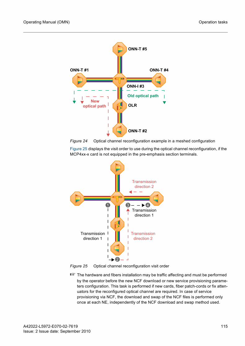
A42022-L5972-E070-02-7619Issue: 2 Issue date: September 2010
115
Operating Manual (OMN) Operation tasks
Figure 24 Optical channel reconfiguration example in a meshed configuration
Figure 25 displays the visit order to use during the optical channel reconfiguration, if the MCP4xx-x card is not equipped in the pre-emphasis section terminals.
Figure 25 Optical channel reconfiguration visit order
☞ The hardware and fibers installation may be traffic affecting and must be performed by the operator before the new NCF download or new service provisioning parame-ters configuration. This task is performed if new cards, fiber patch-cords or fix atten-uators for the reconfigured optical channel are required. In case of service provisioning via NCF, the download and swap of the NCF files is performed only once at each NE, independently of the NCF download and swap method used.
ONN-T #4ONN-T #1
ONN-I #3
ONN-T #2
OLR
ONN-T #5
Old optical pathNew
optical path
4
2
1 3
Transmission
direction 1
Transmission
direction 2
Transmission
direction 1
Transmission
direction 2

116 A42022-L5972-E070-02-7619Issue: 2 Issue date: September 2010
Operating Manual (OMN)Operation tasks
Optical Multiplex Section shutdownAn optical multiplex section shutdown involves deactivating all optical channels in a link section. This service provisioning type is applicable to all ONN types. The link section shutdown is applied for both transmission directions of the optical link between two ONNs, and consequently all channels within the optical link are shutdown. The link section shutdown may be applied to support service provisioning and is described in chapter 4.4.17.
4.4.2.1 Service provisioning via NCFThis section contains the necessary tasks to complete a service provisioning via NCF: channel upgrade, channel downgrade or channel reconfiguration.
Channel upgrade tasksTable 27 displays the optical channel upgrade tasks for example from Figure 20 and Figure 21, and corresponding order, to be performed at each NE visit for precalculated pre-emphasis methods and for enhanced pre-emphasis methods.
NE Optical channel upgrade tasksVisit Order
Transmission direction 1
Transmission direction 2
ONN-T#1
1. Install hardware and fiber cabling, see chapter 4.4.3 visit #1 -
2. Download and swap the new NCF file, see chapter 4.4.4 visit #1 -
3. Configure transponder cards, see chapter 4.4.7 visit #1 -
4. Perform power adjustment, see chapter 4.4.10 visit #11) -
5. Optimize the pre-emphasis section, see chapter 4.4.11 visit #12) visit #62)
6. Update the channel count, see chapter 4.4.13 visit #1 -
7. Adjust drop channels, see chapter 4.4.14 - visit #6
ONN-I
1. Install hardware and fiber cabling, see chapter 4.4.3 visit #2 -
2. Download and swap the new NCF file, see chapter 4.4.4 visit #2 -
3. Configure transponder cards, see chapter 4.4.7 visit #2 -
4. Perform power adjustment, see chapter 4.4.10 visit #21) visit #51)
5. Optimize the pre-emphasis section, see chapter 4.4.11 visit #22) visit #52)
6. Adjust add channels, see chapter 4.4.12.1 visit #2 -
7. Update the channel count, see chapter 4.4.13 visit #2 visit #5
8. Adjust drop channels, see chapter 4.4.14 - visit #5
ONN-T#2
1. Install hardware and fiber cabling, see chapter 4.4.3 visit #3 -
2. Download and swap the new NCF file, see chapter 4.4.4 visit #3 -
3. Configure transponder cards, see chapter 4.4.7 visit #3 -
4. Perform power adjustment, see chapter 4.4.10 - visit #31)
5. Optimize the pre-emphasis section, see chapter 4.4.11 visit #32) visit #32)
6. Update the channel count, see chapter 4.4.13 - visit #3
7. Adjust drop channels, see chapter 4.4.14 visit #3 -
Table 27 Optical channel upgrade tasks for each NE, using the service provisioning via NCF

A42022-L5972-E070-02-7619Issue: 2 Issue date: September 2010
117
Operating Manual (OMN) Operation tasks
The OLRs do not require a visit since they are commissioned remotely from the ONNs in the corresponding sequence.
Channel downgrade tasksTable 28 displays the optical channel downgrade tasks for example from Figure 22 and Figure 23, and corresponding order, to be performed at each NE visit or precalculated pre-emphasis methods and for enhanced pre-emphasis methods.
☞ The NCF download and swap is performed only once at each NE, independently from the NCF download and swap method used.
ONN-S
1. Install hardware and fiber cabling, see chapter 4.4.3 visit #4 -
2. Download and swap the new NCF file, see chapter 4.4.4 visit #4 -
3. Configure transponder cards, see chapter 4.4.7 visit #4 -
4. Adjust add channels, see chapter 4.4.12.2 - visit #4
5. Adjust drop channels, see chapter 4.4.14 visit #4 -
OLR 1. Download and swap the new NCF file, see chapter 4.4.4 - -
1) This task is only applicable to the precalculated pre-emphasis methods.2) This task is only applicable to the enhanced pre-emphasis methods.
NE Optical channel downgrade tasksVisit Order
Transmission direction 1
Transmission direction 2
ONN-T#1
1. Download and swap the new NCF file, see chapter 4.4.4 visit #1 -
2. Perform power adjustment, see chapter 4.4.10 visit #11) -
3. Optimize the pre-emphasis section, see chapter 4.4.11 visit #12) visit #62)
4. Update the channel count, see chapter 4.4.13 visit #1 -
5. Adjust drop channels, see chapter 4.4.14 - visit #6
ONN-I
1. Download and swap the new NCF file, see chapter 4.4.4 visit #2 -
2. Perform power adjustment, see chapter 4.4.10 visit #21) visit #51)
3. Optimize the pre-emphasis section, see chapter 4.4.11 visit #22) visit #52)
4. Update the channel count, see chapter 4.4.13 visit #2 visit #5
5. Adjust drop channels, see chapter 4.4.14 - visit #5
Table 28 Optical channel downgrade tasks for each NE, using the service provision-ing via NCF
NE Optical channel upgrade tasksVisit Order
Transmission direction 1
Transmission direction 2
Table 27 Optical channel upgrade tasks for each NE, using the service provisioning via NCF (Cont.)

118 A42022-L5972-E070-02-7619Issue: 2 Issue date: September 2010
Operating Manual (OMN)Operation tasks
☞ In case of using the enhanced pre-emphasis - manual method, it is required one operator in each pre-emphasis section terminal during the optimization of the pre-emphasis section.
The OLRs do not require a visit since they are commissioned remotely from the ONNs in the corresponding sequence.
Channel reconfigurationTable 29 displays the tasks for example from Figure 24 and Figure 25, and correspond-ing order, to be performed at each NE visit or precalculated pre-emphasis methods and for enhanced pre-emphasis methods.
ONN-T#2
1. Download and swap the new NCF file, see chapter 4.4.4 visit #3 -
2. Perform power adjustment, see chapter 4.4.10 - visit #31)
3. Optimize the pre-emphasis section, see chapter 4.4.11 visit #32) visit #32)
4. Update the channel count, see chapter 4.4.13 - visit #3
5. Adjust drop channels, see chapter 4.4.14 visit #3 -
ONN-S
1. Download and swap the new NCF file, see chapter 4.4.4 visit #4 -
3. Adjust add channels, see chapter 4.4.12.2 - visit #4
2. Update the channel count, see chapter 4.4.13 - visit #4
4. Adjust drop channels, see chapter 4.4.14 visit #4 -
OLR 1. Download and swap the new NCF file, see chapter 4.4.4 - -
1) This task is only applicable to the precalculated pre-emphasis methods.2) This task is only applicable to the enhanced pre-emphasis methods
NE Optical channel reconfiguration tasksVisit Order
Transmission direction 1
Transmission direction 2
ONN-I#3
1. Install hardware and fiber cabling, see chapter 4.4.3 visit #1 -
2. Download and swap the new NCF file, see chapter 4.4.4 visit #1 -
3. Perform power adjustment, see chapter 4.4.10 visit #11) visit #31)
4. Optimize the pre-emphasis section, see chapter 4.4.11 visit #12) visit #32)
5. Update the channel count, see chapter 4.4.13 visit #1 visit #3
Table 29 Optical channel reconfiguration tasks for each NE, using the service provi-sioning via NCF
NE Optical channel downgrade tasksVisit Order
Transmission direction 1
Transmission direction 2
Table 28 Optical channel downgrade tasks for each NE, using the service provision-ing via NCF (Cont.)

A42022-L5972-E070-02-7619Issue: 2 Issue date: September 2010
119
Operating Manual (OMN) Operation tasks
The OLRs do not require a visit since they are commissioned remotely from the ONNs in the corresponding sequence.
4.4.2.2 Service provisioning via NMSThis section contains the necessary tasks to complete a channel upgrade, channel downgrade or channel reconfiguration using the service provisioning via NMS.
g If during the provisioning of a service, the fix attenuation or patch cord between LAx card MonSo port and the input port of MCP card should be changed by other with different attenuation value the LAx Monitoring port loss field must be updated, see chapter 4.4.16.
g If during a service provisioning involving I01R40G cards, the frequency should be changed at an OMS section or one of the I01R40G cards should be logically deleted at the EM, all cross-connections of both I01R40G card and corresponding pair for bidirectional regeneration should be deleted.
Channel upgrade tasksTable 30 displays the optical channel upgrade tasks for example from Figure 20 and Figure 21, and corresponding order, to be performed at each NE visit for precalculated pre-emphasis methods and for enhanced pre-emphasis methods.
ONN-T#2
1. Install hardware and fiber cabling, see chapter 4.4.3 visit #2 -
2. Download and swap the new NCF file, see chapter 4.4.4 visit #2 -
3. Configure transponder cards, see chapter 4.4.7 visit #2 -
4. Perform power adjustment, see chapter 4.4.10 - visit #21)
5. Optimize the pre-emphasis section, see chapter 4.4.11 visit #22) visit #22)
6. Update the channel count, see chapter 4.4.13 - visit #2
7. Adjust drop channels, see chapter 4.4.14 visit #2 -
ONN-T#4
1. Download and swap the new NCF file, see chapter 4.4.4 visit #4 -
2. Perform power adjustment, see chapter 4.4.10 visit #41) visit #41)
3. Optimize the pre-emphasis section, see chapter 4.4.11 visit #42) visit #42)
4. Update the channel count, see chapter 4.4.13 visit #4 visit #4
5. Adjust drop channels, see chapter 4.4.14 visit #4 -
OLR 1. Download and swap the new NCF file, see chapter 4.4.4 - -
1) This task is only applicable for precalculated pre-emphasis methods.2) This task is only applicable for enhanced pre-emphasis methods.
NE Optical channel reconfiguration tasksVisit Order
Transmission direction 1
Transmission direction 2
Table 29 Optical channel reconfiguration tasks for each NE, using the service provi-sioning via NCF (Cont.)

120 A42022-L5972-E070-02-7619Issue: 2 Issue date: September 2010
Operating Manual (OMN)Operation tasks
NE Optical channel upgrade tasksVisit Order
Transmission direction 1
Transmission direction 2
ONN-T#1
1. Install hardware and fiber cabling, see chapter 4.4.3 visit #1 -
2. Configure optical link control parameters, see chapter 4.4.5 visit #11) visit #61)
3. Configure traffic channels settings, see chapter 4.4.6 visit #1 visit #6
4. Configure transponder cards, see chapter 4.4.7 visit #1 -
5. Configure channel provisioning settings, see chapter 4.4.8 visit #1 visit #1
6. Perform power adjustment, see chapter 4.4.10 visit #12) -
7. Optimize the pre-emphasis section, see chapter 4.4.11 visit #13) visit #62)
8. Update the channel count, see chapter 4.4.13 visit #1 -
9. Adjust all drop channels, see chapter 4.4.14 - visit #64)
ONN-I
1. Install hardware and fiber cabling, see chapter 4.4.3 visit #2 -
2. Configure optical link control parameters, see chapter 4.4.5 visit #21) visit #51)
3. Configure traffic channels settings, see chapter 4.4.6 visit #2 visit #5
4. Configure transponder cards, see chapter 4.4.7 visit #2 -
5. Configure channel provisioning settings of the optical path #2 concerned channel, see chapter 4.4.8 visit #2 -
6. Create the port connections following the optical path and link direction of the optical path #1 concerned channel, see chapter 4.3.5
visit #2 visit #2
7. Create the cross connections following the optical path and link direction of the optical path #1 concerned channel, see chapter 4.3.3
visit #2 visit #2
8. Configure the add/drop channel status within the link, see chapter 4.4.9 visit #2 -
9. Perform power adjustment, see chapter 4.4.10 visit #21) visit #51)
10. Optimize the pre-emphasis section, see chapter 4.4.11 visit #22) visit #52)
11. Adjust add channels, see chapter 4.4.12.1 visit #2 -
12. Update the channel count, see chapter 4.4.13 visit #2 visit #5
13. Adjust all drop channels, see chapter 4.4.14 - visit #54)
Table 30 Optical channel upgrade tasks for each NE, using service provisioning via NMS

A42022-L5972-E070-02-7619Issue: 2 Issue date: September 2010
121
Operating Manual (OMN) Operation tasks
The OLRs do not require a visit since no parameters configuration is necessary.
Channel downgrade tasksTable 31 displays the optical channel downgrade tasks for example from Figure 22 and Figure 23, and corresponding order, to be performed at each NE visit for precalculated pre-emphasis methods and for enhanced pre-emphasis methods.
ONN-T#2
1. Install hardware and fiber cabling, see chapter 4.4.3 visit #3 -
2. Configure optical link control parameters, see chapter 4.4.5 visit #31) visit #31)
3. Configure traffic channels settings, see chapter 4.4.6 visit #3 visit #3
4. Configure transponder cards, see chapter 4.4.7 visit #3 -
5. Configure channel provisioning settings, see chapter 4.4.8 visit #3 visit #3
6. Perform power adjustment, see chapter 4.4.10 - visit #31)
7. Optimize the pre-emphasis section, see chapter 4.4.11 visit #32) visit #32)
8. Update the channel count, see chapter 4.4.13 - visit #3
9. Adjust all drop channels, see chapter 4.4.14 visit #34) -
ONN-S
1. Install hardware and fiber cabling, see chapter 4.4.3 visit #4 -
2. Configure traffic channels settings, see chapter 4.4.6 visit #4 visit #4
3. Configure transponder cards, see chapter 4.4.7 visit #4 -
4. Configure channel provisioning settings of the optical path #2 concerned channel, see chapter 4.4.8 visit #4 -
5. Create the port connections following the optical path and link direction of the optical path #1 concerned channel, see chapter 4.3.5
visit #4 -
6. Create the cross connections following the optical path and link direction of the optical path #1 concerned channel, see chapter 4.3.3
visit #4 -
7. Configure the add/drop channel status within the link, see chapter 4.4.9 - visit #4
8. Adjust add channels, see chapter 4.4.12.2 - visit #4
9. Adjust all drop channels, see chapter 4.4.14 visit #44) -
1) This task is only performed in case of MCP card deployment or optical link control modification.
2) This task is only applicable to the precalculated pre-emphasis methods.3) This task is only applicable to the enhanced pre-emphasis methods.4) In case of ONN-RT/I80/R80/RT80/T80/X80, the adjustment of drop channels will be
manually performed if defined in the commissioning report.
NE Optical channel upgrade tasksVisit Order
Transmission direction 1
Transmission direction 2
Table 30 Optical channel upgrade tasks for each NE, using service provisioning via NMS (Cont.)

122 A42022-L5972-E070-02-7619Issue: 2 Issue date: September 2010
Operating Manual (OMN)Operation tasks
NE Optical channel downgrade tasksVisit Order
Transmission direction 1
Transmission direction 2
ONN-T#1
1. Check the optical link control parameters, see chapter 4.4.5 visit #11) visit #61)
2. Configure traffic channel settings, see chapter 4.4.6 visit #1 visit #6
3. Delete the cross connections following the optical path and link direction of the concerned channel, see chapter 4.3.3
visit #1 visit #6
4. Delete the port connections following the optical path and link direction of the concerned channel, see chapter 4.3.5 visit #12) visit #62)
5. Remove the unused cards, see chapter 6.2.2 visit #63) visit #63)
6. Perform power adjustment, see chapter 4.4.10 visit #14) -
7. Optimize the pre-emphasis section, see chapter 4.4.11 visit #15) visit #62)
8. Update the channel count, see chapter 4.4.13 visit #1 -
9. Adjust the remaining drop channels, see chapter 4.4.14 - visit #66)
ONN-I
1. Check optical link control parameters, see chapter 4.4.5 visit #21) visit #51)
2. Configure traffic channel settings, see chapter 4.4.6 visit #2 visit #5
3. Delete the cross connections following the optical path and link direction of the concerned channel, see chapter 4.3.3
visit #2 visit #5
4. Delete the port connections following the optical path and link direction of the concerned channel, see chapter 4.3.5 visit #22) visit #52)
5. Remove the unused cards, see chapter 6.2.2 visit#53) visit #53)
6. Perform power adjustment, see chapter 4.4.10 visit #21) visit #51)
7. Optimize the pre-emphasis section, see chapter 4.4.11 visit #22) visit #52)
8. Update the channel count, see chapter 4.4.13 visit #2 visit #5
9. Adjust the remaining drop channels, see chapter 4.4.14 - visit #56)
ONN-T#2
1. Check optical link control parameters, see chapter 4.4.5 visit #31) visit #31)
2. Configure traffic channel settings, see chapter 4.4.6 visit #3 visit #3
3. Delete the cross connections following the optical path and link direction of the concerned channel, see chapters 4.3.3
visit #3 visit #3
4. Delete the port connections following the optical path and link direction of the concerned channel, see chapter 4.3.5 visit #32) visit #32)
5. Remove the unused cards, see chapter 6.2.2 visit #33) visit #33)
6. Perform power adjustment, see chapter 4.4.10 - visit #31)
7. Optimize the pre-emphasis section, see chapter 4.4.11 visit #32) visit #32)
8. Update the channel count, see chapter 4.4.13 - visit #3
9. Adjust the remaining drop channels, see chapter 4.4.14 visit #36) -
Table 31 Optical channel downgrade tasks for each NE, using service provisioning via NMS

A42022-L5972-E070-02-7619Issue: 2 Issue date: September 2010
123
Operating Manual (OMN) Operation tasks
The OLRs do not require a visit since no parameters configuration is necessary.
After performing the tasks described in Table 31, if the hardware previously used in the downgraded channel is not being used by other service or is not required to provision a new channel, it is recommended to remove it from the system, including the unused patch cords and port connections along the cross connections path between transpon-der and filter. The removal of the hardware may be delayed until the operator visits the concerned site, nevertheless the correspondent card slot state must be set to empty. If not possible to remove the transponder card used by the downgraded channel, instead of setting the card slot state to empty, the provisioning mode of correspondent client port and line port must be set to empty.
g If a VOA card for alien wavelength or a client interface with line side functionality is deleted or the correspondent port connection is deleted, then it is necessary to delete also the concerning cross connection. If the cross connection is not deleted, and the VOA card is recreated (and/or the correspondent port connection is recre-ated) the traffic will only be activated after the concerning cross connection is deleted and re-established.
Channel reconfigurationTable 32 displays the tasks for example from Figure 24 and Figure 25, and correspond-ing order, to be performed at each NE visit for precalculated pre-emphasis methods and for enhanced pre-emphasis methods.
ONN-S
1. Configure traffic channel settings, see chapter 4.4.6 visit #4 visit #4
2. Delete the cross connections following the optical path and link direction of the concerned channel, see chapter 4.3.3
visit #4 visit #4
3. Delete the port connections following the optical path and link direction of the concerned channel, see chapter 4.3.5 visit #42) visit #42)
4. Remove the unused cards, see chapter 6.2.2 visit #43) visit #43)
5. Adjust add channels, see chapter 4.4.12.2 - visit #4
6. Update the channel count, see chapter 4.4.13 - visit #4
5. Adjust the remaining drop channels, see chapter 4.4.14 visit #46) -
1) This task is only performed in case of MCP card deployment or optical link control parameters modification.
2) This task may not be necessary to perform if the concerning port connections are required for provisioning a new service using the same physical resources.
3) This task is only applicable if the cards are not required to provision an existing service or a new service.
4) This task is only applicable to the precalculated pre-emphasis methods.5) This task is only applicable to the enhanced pre-emphasis methods6) In case of ONN-RT/I80/R80/RT80/T80/X80, the adjustment of drop channels will be
manually performed if defined in the commissioning report.
NE Optical channel downgrade tasksVisit Order
Transmission direction 1
Transmission direction 2
Table 31 Optical channel downgrade tasks for each NE, using service provisioning via NMS (Cont.)

124 A42022-L5972-E070-02-7619Issue: 2 Issue date: September 2010
Operating Manual (OMN)Operation tasks
NE Optical channel reconfiguration tasksVisit Order
Transmission direction 1
Transmission direction 2
ONN-I#3
1. Install hardware and fiber cabling, see chapter 4.4.3 visit #1 -
2. Configure optical link control parameters, see chapter 4.4.5 visit #11)
1) This task is only applicable in case of MCP card deployment or optical link control modification.
visit #31)
3. Delete the cross connections following the optical path and link direction of the old optical path, see chapter 4.3.3 visit #1 -
4. Delete the port connections following the optical path and link direction of the old optical path, see chapter 4.3.3 visit #1 -
5. Create the new port connections following the optical path and link direction of the new optical path, see chapter 4.3.3
visit #1 -
6. Create the new port connections following the optical path and link direction of the new optical path, see chapter 4.3.3
visit #1 -
7. Perform power adjustment, see chapter 4.4.10 visit #12)
2) This task is only applicable for precalculated pre-emphasis methods.
visit #31)
8. Optimize the pre-emphasis section, see chapter 4.4.11 visit #13)
3) This task is only applicable for enhanced pre-emphasis methods.
visit #32)
9. Update the channel count, see chapter 4.4.13 visit #1 visit #3
ONN-T#2
1. Install hardware and fiber cabling, see chapter 4.4.3 visit #2 -
2. Configure optical link control parameters, see chapter 4.4.5 visit #21) visit #21)
3. Configure transponder cards, see chapter 4.4.7 visit #2 -
4. Configure channel provision settings, see chapter 4.4.8 visit #2 visit #2
5. Perform power adjustment, see chapter 4.4.10 - visit #21)
6. Optimize the pre-emphasis section, see chapter 4.4.11 visit #22) visit #22)
7. Update the channel count, see chapter 4.4.13 - visit #2
8. Adjust drop channels, see chapter 4.4.14 visit #24)
4) In case of ONN-RT/I80/R80/RT80/T80/X80, the adjustment of drop channels will be manually performed if defined in the commissioning report.
-
ONN-T#4
1. Delete the cross connections following the optical path and link direction of the old optical path, see chapter 4.3.3 visit #4 visit #4
2. Delete the port connections following the optical path and link direction of the old optical path, see chapters 4.3.5 visit #4 visit #4
3. Remove the unused cards, see chapter 6.2.2 visit #45) visit #45)
4. Perform power adjustment, see chapter 4.4.10 visit #41) visit #41)
5. Optimize the pre-emphasis section, see chapter 4.4.11 visit #42) visit #42)
6. Update the channel count, see chapter 4.4.13 visit #4 visit #4
7. Adjust drop channels, see chapter 4.4.14 visit #44) -
Table 32 Optical channel reconfiguration tasks for each NE, using service provision-ing via NMS

A42022-L5972-E070-02-7619Issue: 2 Issue date: September 2010
125
Operating Manual (OMN) Operation tasks
The OLRs do not require a visit since no parameters configuration is necessary.
4.4.3 Installing hardware and fiber cablingThe sequence of hardware installation and fiber cabling is important in order to minimize any power transient caused by the upgraded channels.
Install any hardware (rack, shelves and cards), cabling and attenuators in the given sequence:
1 Travel to the site of the ONN and establish a local connection to the NE.
2 Install the necessary rack and shelves. Ground and connect the power of the rack and shelves with the support of SURPASS TransNet commissioning reports and as described in Installation and Test Manual (ITMN).
3 Install the necessary cards with the support of SURPASS TransNet commissioning reports and as described in chapter 6.2.2.
4 Set the user label field in every replaced/added card, as described in chapter 6.2.6.
5 Depending on the type of attenuators used, select one of the following:a) If using fix attenuators, proceed to step 6.b) If using VOAs or an F40MR-1, after the NCF file is swapped, the attenuation
value will be adjusted to the values specified by the SURPASS TransNet com-missioning reports, proceed to step 7.
6 Add/Drop each new channel individually, using fix attenuators by plugging the required fix attenuator patch cord, indicated by the SURPASS TransNet commis-sioning report, to the corresponding input port of the Mux/Demux.
Repeat step 6 for all added/dropped channels.
7 Establish the remaining fiber connections with the support of SURPASS TransNet commissioning reports and the Interconnect, Configuration and Mechanical Assembly (ICMA).
The hardware is installed and the fiber is cabled.
4.4.4 Downloading and swapping the new NCF fileThe download and swap of the new NCF file must be performed for all involved NEs (except for SON/SONF) and is only applicable in case of service provisioning via NCF. To perform the download and swap of the NCF file, complete the following steps:
1 Depending on the pre-emphasis method used and on the transponder cards used, select one of the following options:
a) If using enhanced pre-emphasis - automated method and alien transponders, disable the line laser from the corresponding alien transponders via Element Manager or ensure that the fiber from the alien transponder line laser Tx port is disconnect from the multiplexer input port. The alien transponder laser from line side must not transmit light towards the multiplexer input port.Proceed to step 2, to download and swap the NCF file.
b) Otherwise, proceed to step 2.
5) This task is only applicable if the cards are not required to provision an existing service or a new service.
126 A42022-L5972-E070-02-7619Issue: 2 Issue date: September 2010
Operating Manual (OMN)Operation tasks
2 Select one of the following options, to download and swap the NCF files:
a) In case of downloading and swapping the NCF file simultaneously to all NEs, using the TransNet archive, complete the procedure described in chapter 6.4.8.
b) In case of downloading and swapping the NCF file individually to each NE, complete the procedure described in chapter 6.4.7.
3 Depending on the pre-emphasis method used and on the transponder cards used, select one of the following options:
a) If using enhanced pre-emphasis - automated method and alien transponders, enable the alien transponders line laser or connect the fiber from the alien tran-sponder line laser Tx port.The download and swap of the NCF file is complete.
b) Otherwise, the download and swap of the NCF file is complete.
The download and swap of the NCF file procedure is completed.
4.4.5 Configuring optical link control parametersThis section is only applicable in case MCP cards are deployed or optical link control is modified during a service provisioning operation and if using service provisioning via NMS. The link control parameters must be configured according with the SURPASS TransNet commissioning report.
Configuring booster optical link control parametersTo configure the optical link control parameters at the booster card for the correspondent link direction, complete the following steps:
1 In the Shelf Equipment window, right-click on the LAxB or LAxI card replica and select the Traffic > Configuration....The <shelf Id>-<slot number> <card name> - Traffic Configuration window is opened.
2 In the Optical Link Control tab, select the measurement mode option from the Measurement mode drop-down menu, according with the SURPASS TransNet commissioning report.
3 Depending on the SURPASS TransNet commissioning report information, select one of the following option:
a) If continuous tilt control is enabled, in the Optical Link Control tab, select the Continuous tilt control checkbox.Click the Apply to confirm the settings.
b) If continuous drop control is disabled, in the Optical Link Control tab, clear the Continuous tilt control checkbox.Click the Apply to confirm the settings.
The booster optical link control parameters are configured.
Configuring preamplifier optical link control parametersTo configure the optical link control parameters at the preamplifier card for the corre-spondent link direction, complete the following steps:

A42022-L5972-E070-02-7619Issue: 2 Issue date: September 2010
127
Operating Manual (OMN) Operation tasks
1 In the Shelf Equipment window, right-click on the LAxP or LAxI card replica and select the Traffic > Configuration....The <shelf Id>-<slot number> <card name> - Traffic Configuration window is opened.
2 Depending on the SURPASS TransNet commissioning report information, select one of the following option:
a) If continuous drop control is enabled, in the Optical Link Control tab, select the Continuous drop control checkbox.Click the Apply to confirm the settings.
b) If continuous drop control is disabled, in the Optical Link Control tab, clear the Continuous drop control checkbox.Click the Apply to confirm the settings.
3 In the Optical Link Control tab, select the measurement mode option from the Measurement mode drop-down menu, according with the SURPASS TransNet commissioning report.
Click the Apply to confirm the settings.
The preamplifier optical link control parameters are configured.
4.4.6 Configuring traffic channel settingsThis chapter contains information concerning the configuration of the optical channel traffic settings through the channel transmission path at LAxB and LAxP cards. The pro-cedures described in this chapter are only applicable in case of service provisioning via NMS.
Depending on the location of the NE in transmission path of the concerned channel, dif-ferent parameters must be checked or configured. Select one of the following proce-dures, considering the NE location at the optical channel transmission path:
a) To configure the traffic channel settings at the head end NE of the transmission path, complete the procedure described in section 4.4.6.1.
b) To configure the traffic channel settings in an intermediate NE where the channel is neither added or dropped, complete the procedure described in section 4.4.6.2.
c) To configure the traffic channel settings at the tail end NE of the transmission path, complete the procedure described in section 4.4.6.3.
OSNR power correctionDuring the execution of the traffic channel settings configuration, it is possible to verify the total per channel power correction for the given OMS at the OSNR power correc-tion field from Traffic Channel Configuration window of LAxB card. This parameter results from the sum of the modulation format dependent power correction value (calcu-lated by SURPASS TransNet for each OMS) with the Ingress power correction parameter (configured at the head end NE of the transmission path, as described at chapter 4.4.6.1). The bit rate and modulation format is displayed at the Transponder OSNR Type field from Traffic Channel Configuration window of LAxB card and the power correction value (dependent from the modulation format) is visible at Traffic Con-figuration window of LAxB card in 40G DPSK or 40G CPQPSK fields from OSNR Power Correction area. If the Transponder OSNR Type field displays Other, the tran-sponder card supports optical signals with 10Gbit/s or 2.5Gbit/s bit rate and the modu-lation format dependent power correction value is 0dB.

128 A42022-L5972-E070-02-7619Issue: 2 Issue date: September 2010
Operating Manual (OMN)Operation tasks
4.4.6.1 Configuring traffic channel settings at the head end NE
Configuring traffic channel settings for channel upgrade To configure the optical channel traffic settings at the head end NE of the transmission path, complete the following steps:
1 In the Shelf Equipment window, right-click on the LAxB card replica and select the Traffic > Channel Configuration....The <shelf Id>-<slot number> <card name> - Traffic Channel Configuration window is opened.
2 In the Filter area, select the required frequency spacing item from the Frequency spacing drop-down menu.
Click Enable to enable the required frequency spacing grid.
3 In the corresponding row of the target wavelength, using the provided values (from commissioning report, if used), check and configure the following channel parame-ters:
4 In the corresponding row of the target wavelength, check the Ingress power cor-rection [-99.9... 20.0 dBm] field value. The ingress power correction field must display 0dB. If necessary, set this parameter to 0dB.
g The ingress power correction parameter is configured at the head end of the transmission path and may be used to adjust the optical power of an optical channel through the respective transmission path. Changing the value of this parameter may affect traffic performance.
5 Repeat steps 1 to 4 to configure the remaining channels.
The traffic channel configuration at the head end of the transmission path is completed.
☞ The equivalent TL1 command to perform the traffic channel configuration at the head end NE of the transmission path is listed below.
For additional information, please refer to the TL1 Command and Message List (CML) document.
Mux loss [0.0... 25.0 dB] Attenuation value caused by optical multiplexing structure modification.
If a new F04MDx card is deployed, the Mux loss [0.0... 25.0 dB] parameter must be configured for all channels (routed and not routed through the new card).
Additional loss [0.0... 15dB] Additional loss value caused by, e.g., added/removed patch cords or additional equip-ment.
Ingress power [-99.9... 20.0 dBm]
Ingress power value from the wavelengths used by the system. The ingress power value from the wavelengths provided by other vendors optical equipment must be configured in this field.
ED-OCH

A42022-L5972-E070-02-7619Issue: 2 Issue date: September 2010
129
Operating Manual (OMN) Operation tasks
Configuring traffic channel settings for channel downgrade To configure the optical channel traffic settings at the head end NE of the transmission path, complete the following steps:
1 In the Shelf Equipment window, right-click on the LAxB card replica and select the Traffic > Channel Configuration....The <shelf Id>-<slot number> <card name> - Traffic Channel Configuration window is opened.
2 In the Filter area, select the required frequency spacing item from the Frequency spacing drop-down menu.
Click Enable to enable the required frequency spacing grid.
3 In the corresponding row of the target wavelength, configure the channel parame-ters with the following values:
4 Repeat steps 1 to 3 to configure the remaining channels.
The traffic channel configuration at the head end of the transmission path is completed.
☞ The equivalent TL1 command to perform the traffic channel configuration at the head end NE of the transmission path is listed below.
For additional information, please refer to the TL1 Command and Message List (CML) document.
4.4.6.2 Configuring traffic channel settings at an intermediate NEThis procedure is applicable in case of ONN-I, ONN-I80 and ONN-R (if using F40/F40V cards). In case of ONN-R2/R80/RT/RT80/X/X80 and ONN-R (without using F40/F40V cards), Demux loss and Mux loss parameters are not possible to configure.
In an intermediate NE, the Additional loss [0.0... 15 dB] parameter must display 0dB.
Configuring traffic channel settings for channel upgradeTo configure the optical channel traffic settings at an intermediate NE of the transmis-sion path, complete the following steps:
1 In the Shelf Equipment window, right-click on the LAxP card replica and select the Traffic > Channel Configuration....The <shelf Id>-<slot number> <card name> - Traffic Channel Configuration window is opened.
2 In the Filter area, select the required frequency spacing item from the Frequency spacing drop-down menu.
Click Enable to enable the required frequency spacing grid.
3 In the corresponding row of the target wavelength, using the provided values (from commissioning report, if used), check and configure the following channel parame-ter:
Additional loss [0.0... 15 dB] 0 dB
Ingress power [-99.9... 20.0 dBm] -99.9 dBm
ED-OCH

130 A42022-L5972-E070-02-7619Issue: 2 Issue date: September 2010
Operating Manual (OMN)Operation tasks
Click Apply to confirm the settings.
4 Repeat steps 1 to 3 to configure the remaining channels.
5 In the Shelf Equipment window, right-click on the LAxB card replica and select the Traffic > Channel Configuration....The <shelf Id>-<slot number> <card name> - Traffic Channel Configuration window is opened.
6 In the Filter area, select the required frequency spacing item from the Frequency spacing drop-down menu.
Click Enable to enable the required frequency spacing grid.
7 In the corresponding row of the target wavelength, using the provided values (from commissioning report, if used), check and configure the following channel parame-ter:
8 Repeat steps 5 to 7 to configure the remaining channels.
The traffic channel configuration at an intermediate NE of the transmission path is com-pleted.
☞ The equivalent TL1 command to perform the traffic channel configuration at an inter-mediate NE of the transmission path is listed below.
For additional information, please refer to the TL1 Command and Message List (CML) document.
Configuring traffic channel settings for channel downgradeIn case of a channel downgrade, the traffic channel settings configuration at an interme-diate NE is not necessary to perform.
4.4.6.3 Configuring traffic channel settings at the tail end NE
Configuring traffic channel settings for channel upgradeTo configure the optical channel traffic settings at the tail end NE of the transmission path, complete the following steps:
Demux loss [0.0... 25.0 dB] Attenuation value caused by optical demultiplexing structure modification.
If a new F04MDx card is deployed, the Demux loss [0.0... 25.0 dB] parameter must be configured for all channels (routed and not routed through the new card).
Mux loss [0.0... 25.0 dB] Attenuation value caused by optical multiplexing structure modification.
If a new F04MDx card is deployed, the Mux loss [0.0... 25.0 dB] parameter must be configured for all channels (routed and not routed through the new card).
ED-OCH

A42022-L5972-E070-02-7619Issue: 2 Issue date: September 2010
131
Operating Manual (OMN) Operation tasks
1 In the Shelf Equipment window, right-click on the LAxP card replica and select the Traffic > Channel Configuration....The <shelf Id>-<slot number> <card name> - Traffic Channel Configuration window is opened.
2 In the Filter area, select the required frequency spacing item from the Frequency spacing drop-down menu.
Click Enable to enable the required frequency spacing grid.
3 In the corresponding row of the target wavelength, using the provided values (from commissioning report, if used), check and configure the following channel parame-ters:
Click Apply to confirm the settings.
4 Repeat steps 1 to 3 to configure the remaining channels.
The traffic channel configuration at the tail end NE of the transmission path is completed.
☞ The equivalent TL1 command to configure Demux loss and Additional loss param-eters at the tail end NE of the transmission path is listed below.
For additional information, please refer to the TL1 Command and Message List (CML) document.
Configuring traffic channel settings for channel downgradeTo configure the optical channel traffic settings at the tail end NE of the transmission path, complete the following steps:
1 In the Shelf Equipment window, right-click on the LAxP card replica and select the Traffic > Channel Configuration....The <shelf Id>-<slot number> <card name> - Traffic Channel Configuration window is opened.
2 In the Filter area, select the required frequency spacing item from the Frequency spacing drop-down menu.
Click Enable to enable the required frequency spacing grid.
3 In the corresponding row of the target wavelength, configure the channel parame-ters with the following values:
Demux loss [0.0... 25.0 dB] Attenuation value caused by optical demultiplex-ing structure modification.
If a new F04MDx card is deployed, the Demux loss [0.0... 25.0 dB] parameter must be config-ured for all channels (routed and not routed through the new card).
Additional loss [0.0... 15 dB] Additional loss value caused by, e.g., added/removed patch cords or fixed attenuators.
Target drop power [-99.9... 20.0 dBm]
Transponder receiver input power value.
ED-OCH

132 A42022-L5972-E070-02-7619Issue: 2 Issue date: September 2010
Operating Manual (OMN)Operation tasks
Click Apply to confirm the settings.
4 Repeat steps 1 to 3 to configure the remaining channels.
The traffic channel configuration at the tail end NE of the transmission path is completed.
☞ The equivalent TL1 command to configure Demux loss and Additional loss param-eters at the tail end NE of the transmission path is listed below.
For additional information, please refer to the TL1 Command and Message List (CML) document.
4.4.7 Configuring Transponder cardsSURPASS hiT 7300 can accept signals from transponders other than that from Nokia Siemens Networks. If alien transponders are used, the following must be taken into account:
• If alien transponders are used, Automatic Laser Shutdown (ALS) must be turned OFF before performing the link start-up. The ALS is turned ON after link start up.
• For every three ADVA transponders used on a link, with ALS “ON”, at least one SURPASS hiT 7300 transponder has to be used with the ALS “OFF“.
For each transponder card ensure that: • The Line Out port of the transponder is connected to the corresponding input port of
the multiplexer with the correct attenuator, according to the SURPASS TransNet commissioning report.
• The Line In port of the transponder is connected to the corresponding output port of the demultiplexer with the correct attenuator, according to the SURPASS TransNet commissioning report.
Additionally, it is necessary to configure parameters of the transponder cards via EM by completing the following steps:
1 Configure the client mode for the transponder card, as described in chapter 6.2.17.
2 In case of client side with line side functionality or O02CSP with line side protection scenarios, configure the optical channel for the transponder card, as described in chapter 6.2.18.
3 Configure the LOS forwarding function of a client interface, as described in chapter 6.2.20.
4 Select the Alarm Indication Signal (AIS) operation mode of a client interface, as described in chapter 6.2.21.
5 Configure the supervision mode of all the ports, as described in chapter 6.2.34.
6 Check the provisioning mode of the used client and line ports as described in chapter 6.2.13. If necessary, set the provisioning mode of the concerned port to Used.
The transponder card parameters are configured.
Additional loss [0.0... 15 dB] 0 dB
Target drop power [-99.9... 20.0 dBm] -99.9 dBm
ED-OCH

A42022-L5972-E070-02-7619Issue: 2 Issue date: September 2010
133
Operating Manual (OMN) Operation tasks
4.4.8 Configuring channel provision settingsThis chapter contains the necessary information to configure the channel provisioning settings concerning port and cross connections creation. It is possible to create three types of connections:
• Port connection (PC) • Add cross connection (Add CC) • Drop cross connection (Drop CC)
☞ If during the channel provisioning settings configuration an error message should be displayed, the selected resource (card or port) is not possible to use and the channel provision is not possible to create. Close the <shelf Id>-<slot number> <card name> <frequency> Channel Provision window and check the commissioning report or the planning data.
☞ This procedure is not applicable in case of transponders client side with line func-tionality. In case of transponders client side with line functionality, first the port con-nections must be created using the procedure described in chapter 4.3.5 and afterward the cross connections must be created using the procedure described in chapter 4.3.3.
To configure the channel provisioning settings, complete the following steps:
1 In the Shelf Equipment window of the EM, right-click on the transponder card replica and select the Channel Provision > Line# <line number> item.
The <shelf Id>-<slot number> <card name> <frequency> - Channel Provision Information window is opened.
2 Select the Please confirm! checkbox to confirm that all optical channel setting are configured for the right direction.
Click Next to proceed with the channel provisioning settings.
3 Check the selected transponder. In the Selected transponder line port area, check the following fields (with commissioning report, if used):
4 Depending on the type of transponder used, select one of the following options:
a) In case of using 40G transponder cards and OPMDC card at the tail end NE of the optical channel transmission path, in the Optical polarization mode disper-sion compensator area, select the OPMDC card from the drop-down menu.
b) Otherwise, proceed to the next step.
5 Depending on the usage of transponder line protection, select one of the following options:
a) In case of using transponder line protection, in the Transponder line protec-tion area, configure the following fields:
b) Otherwise, proceed to the next step.
Location Check transponder location (shelf/slot/card name).
Port Check the port reference.
Frequency Check the frequency of the target channel.
O02CSP card Select the O02CSP card from drop-down menu.
Port Select the corresponding port.

134 A42022-L5972-E070-02-7619Issue: 2 Issue date: September 2010
Operating Manual (OMN)Operation tasks
6 In the Working path area, select the transmission direction from the Direction drop-down menu.
7 Depending on the usage of the F09MDRT card in the current transmission direction, select one of the following options:
a) If using the F09MDRT card, in the Filter port area, configure the following fields:
b) Otherwise, proceed to the next step.
8 In the VOA selection area, configure the following fields from the Add path area:
9 In the VOA selection area, configure the following fields from the Drop path area:
10 In case of using transponder line protection, in the Protection path area, select the transmission direction from the Direction drop-down menu.
Repeat steps 7 to 9 to configure the filter port and VOA selection correspondent to the protection path.
11 Click Next to confirm the settings.
The <shelf Id>-<slot number> <card name> <frequency> Channel Provision window is opened with a list of the port and cross connections to be created. The state of port and cross connections is To be created.
12 If required, select the Create also the cross connections checkbox to create the cross connections.
13 Select the Allow above connections to be created checkbox to complete the con-nection creation. Click Next to confirm the settings.
The system will take some seconds to calculate the connections creation result.
The <shelf Id>-<slot number> <card name> <frequency> Channel Provision window is updated with the list of port and cross connections and corresponding creation result state.
14 Check the State field of the created connections. Depending on the state of the created connections, select one of the following options:
a) In case the State field of all connections displays Done, the channel provision is successfully completed. Click Finish button.
b) In case the State field of one or more connections displays Skipped, the con-cerned connection is already created but the channel provision is successfully completed.Click Finish button.
F09MDRT card Select the required F09MDRT card from the drop-down menu.
Port Select the required port from the drop-down menu.
O08VA card Select the required O08VA card from the drop-down menu.
Port Select the required port from the drop-down menu.
O08VA card Select the required O08VA card from the drop-down menu.
Port Select the required port from the drop-down menu.

A42022-L5972-E070-02-7619Issue: 2 Issue date: September 2010
135
Operating Manual (OMN) Operation tasks
c) In case the State field of one or more connections displays Failed, the con-cerned connection is not possible to create and the channel provision is not suc-cessfully completed.Click Back button. The Remove connections window is opened. Click Remove all connection button, check planning data or the cause of the con-nection creation failure and repeat the procedure.
The configuration of the channel provisioning settings is completed.
4.4.9 Configuring add/drop channel status within the linkThe procedure described in this chapter is only applicable to add/drop channels (chan-nels added/dropped in an ONN-S).To configure the channel status within the link, complete the following steps at the booster card:
1 In the Shelf Equipment window of the EM, right-click on the LAxB card replica and select the Traffic > Channel Configuration....The <shelf Id>-<slot number> <card name> - Traffic Channel Configuration window is opened.
2 In the corresponding row of the target wavelength, select the status Add/drop option from the Configured channel status within the link drop-down menu.
Click Apply to confirm the settings.
The add/drop channel status within the link configuration is completed.
4.4.10 Performing power adjustmentThe power adjustment consists in adjusting the power levels of all channels to the SURPASS TransNet precalculated values. The power adjustment must be performed before the optical link start-up and after channel upgrade/downgrade operations at each pre-emphasis section head end (ONN-I/R/T/X or ONN-I80/R80/T80/X80). It is possible to perform the power adjustment with the following measurement types:
• Without measurement • With measurement using an OSA • With measurement using an F40MR-1 card • With measurement using an MCP4xx-x card
The power adjustment procedure has to be performed for all pre-emphasis methods.
For channels without VOAs, verify that the attenuators or attenuation patch-cords are installed at the pre-emphasis sections head end ONN-I/R/R2/RT/T/X, or ONN-I80/R80/RT80/T80/X80, as specified in the SURPASS TransNet commissioning reports.
4.4.10.1 Without MeasurementThe power adjustment without measurement is applicable to the precalculated pre-emphasis without measurement method. In this case, no personnel intervention is nec-essary to obtain further measurement values, the NE will adjust the power values accordingly with reference power values, calculated by SURPASS TransNet. If the Link Status of this link section is Running, no action is required from operator.

136 A42022-L5972-E070-02-7619Issue: 2 Issue date: September 2010
Operating Manual (OMN)Operation tasks
If the Link Status of this link section is Prestart, to perform the power adjustment without measurement, complete the following steps:
1 In the Shelf Equipment window of the EM, right-click on the LAxB card replica and select the Traffic > Configuration... menu item.
The <shelf Id>-<slot number> <card name> - Traffic Configuration window is opened.
2 In the Optical Link Control tab, in the Power Adjustment area click the No Mea-surement... button.
A warning message is opened. Click the Yes button to proceed with the power adjustment.
The <shelf Id>-<slot number> <card name> - Power Adjust Result window is opened once the calculation of the power adjust values is completed.
3 Check the VOA attenuation value in the Initial Attenuation field and select one of the following options:
a) If the new VOA attenuation value is displayed, the power adjustment without measurement procedure is complete.
b) If the new VOA attenuation value is not displayed, check the Operation Results field in the Optical Link Control tab and check the correspondent optical channel state at the upstream NE.
The VOA attenuation value changes to the new value if the corresponding optical channel is enabled at the upstream ONN.
The power adjustment without measurement procedure is complete.
4.4.10.2 With measurement using an OSAFor ONN-I/R/T or ONN-I80/R80/T80 NEs, an external OSA may be required for measur-ing the spectrum power levels at the output of the LAx cards. The OSA requirements and parameter settings to perform the optical spectrum measurements are described in chapter 7.
To perform a power adjustment with measurement using an OSA, complete the follow-ing steps:
1 In the Shelf Equipment window of the EM, right-click on the LAxB card replica and select the Traffic > Configuration... menu item.
The <shelf Id>-<slot number> <card name> - Traffic Configuration window is opened.
2 In the Optical Link Control tab, in the Power Adjustment area click the Manual Measurement... button.
The <shelf Id>-<slot number> <card name> - Power Adjust window is opened.
The LAxB booster laser is switched on.
3 Connect an OSA to the MonSo port of the LAxB card and measure the power of each valid channel.

A42022-L5972-E070-02-7619Issue: 2 Issue date: September 2010
137
Operating Manual (OMN) Operation tasks
Figure 26 OSA measurement setup for power adjustment with measurement using an OSA
4 In the <shelf Id>-<slot number> <card name> - Power Adjust window, enter the measured values using one of the following options:
a) If manually inserting measured values, for each valid channel enter the measured power values in the Measured Power column.
b) If using a data file to insert measured values, click the Load button and select the file to upload. The file must have the format described in chapter 7.6.
5 Click the Calculate button to start the power adjustment.
The <shelf Id>-<slot number> <card name> - Power Adjust Result window is opened, once the calculation of the delta power adjustment values is completed.
If the Link Status of this link section is Prestart, the LAxB card laser is switched on until the delta power adjustment values are calculated.
6 Read the calculated delta attenuation value for each channel, displayed in the Power Adjust Delta Attenuation [dBm] column and select one of the following options:
a) For ONN-I/R/T, or ONN-I80/R80/T80, channels with fixed attenuators, if the delta attenuation values are outside the range [- 2.5... 2.5 dB], replace these attenuators at the MX-IN ports. Repeat steps 2 and 6.
b) For ONN-I/R/T, or ONN-I80/R80/T80, channels with VOAs, if the delta attenua-tion values are outside the range [- 0.6... 0.6 dB], perform another power adjust-ment by repeating steps 2 to 6, until this range is reached.
c) For ONN-I/R/T, or ONN-I80/R80/T80, channels with VOAs, if the delta attenua-tion values are not displayed, check the Operation Results field in the Optical Link Control tab and check the correspondent optical channel state at the upstream NE.The delta attenuation is displayed if the corresponding optical channel is enabled at the upstream ONN.
ONN-T
..
.
OLR ONN-T
OSA
EM
..
.
..
.
..
.

138 A42022-L5972-E070-02-7619Issue: 2 Issue date: September 2010
Operating Manual (OMN)Operation tasks
The power adjustment with measurement using an OSA is completed.
☞ The Manual Measurement.... button is always active. If during this procedure, the Manual Measurement... button should be pressed by other user, the first power adjustment command is aborted and an error message is displayed.
4.4.10.3 With measurement using an F40MR-1 cardIf the Link Status of this link section is Prestart, it is necessary to perform the first power adjustment using an OSA, as described in section 4.4.10.2.
To perform power adjustment with measurement using an F40MR-1, complete the fol-lowing steps:
1 In the Shelf Equipment window of the EM, right-click on the LAxB card replica and select the Traffic > Configuration... menu item.
The <shelf Id>-<slot number> <card name> - Traffic Configuration window is opened.
2 In the Optical Link Control tab, in the Power Adjustment area click the Automatic Measurement... button.
The <shelf Id>-<slot number> <card name> - Power Adjust Result window is opened.
Click the Update button and check the attenuation values in the Power Adjust Delta Attenuation field. The VOAs are set automatically, if the corresponding optical channels are enabled at the upstream ONN.
3 Read the calculated delta attenuation value for each channel, displayed in the Power Adjust Delta Attenuation [dBm] column and select one of the following:
a) If the delta attenuation values are outside the range [- 0.6... 0.6 dB], perform another power adjustment by repeating steps 2 and 3, until this range is reached.
b) If the delta attenuation values are not displayed, check the Operation Results field in the Optical Link Control tab and check the correspondent optical channel state at the upstream NE.The delta attenuation is displayed if the corresponding optical channel is enabled at the upstream ONN.
The power adjustment with measurement using an F40MR-1 is completed.
4.4.10.4 With measurement using an MCP4xx-x cardIf an MCP4xx-x card is used, the measured power of each valid channel data is auto-matically available to perform the power adjustment. If the Link Status of this link section is Running and the pre-emphasis mode is continuous, no action is required from operator.
If the Link Status of this link section is Prestart or if the pre-emphasis mode is manual, complete the following steps to perform a power adjustment:
1 In the Shelf Equipment window of the EM, right-click on the LAxB card replica and select the Traffic > Configuration... menu item.
The <shelf Id>-<slot number> <card name> - Traffic Configuration window is opened.

A42022-L5972-E070-02-7619Issue: 2 Issue date: September 2010
139
Operating Manual (OMN) Operation tasks
2 In the Optical Link Control tab, in the Power Adjustment area click the Automatic Measurement... button.
The <shelf Id>-<slot number> <card name> - Power Adjust Result window is opened.
Click the Update button and check the attenuation values in the Power Adjust Delta Attenuation field. The VOAs are set automatically, if the corresponding optical channels are enabled at the upstream ONN.
3 Read the calculated delta attenuation value for each channel, displayed in the Power Adjust Delta Attenuation [dBm] column and select one of the following:
a) If the channels are equipped with fixed attenuators, and if the delta attenuation values are outside the range [- 2.5... 2.5 dB], replace these attenuators at the MX-IN ports. Repeat steps 2 and 3.
b) If the channels are equipped with VOAs, and if the delta attenuation values are outside the range [- 0.6... 0.6 dB], perform another power adjustment by repeat-ing steps 2 and 3, until this range is reached.
c) For ONN-I/R/T, or ONN-I80/R80/T80, channels with VOAs, if the delta attenua-tion values are not displayed, check the Operation Results field in the Optical Link Control tab and check the correspondent optical channel state at the upstream NE.The delta attenuation is displayed if the corresponding optical channel is enabled at the upstream ONN.
In case the Link Status of this link section is Prestart, the LAxB card laser is switched on until the delta power adjustment values are calculated.
The power adjustment with measurement using an MCP4xx-x card is completed.
4.4.11 Optimizing the pre-emphasis sectionOnce an entire pre-emphasis section has been sequentially started, the channels equipped with VOAs at their multiplexer input may need further optimization. Only the express channels are optimized in this operation.
Optimizing the pre-emphasis section can be performed using the following pre-emphasis methods:
• Enhanced pre-emphasis - manual (Tx and Rx measurements). • Enhanced pre-emphasis - automated.
If the optimization of the pre-emphasis section is being achieved by using the pre-emphasis section - automated method, no personnel intervention is necessary as it is performed automatically every 300 seconds.This pre-emphasis method is applicable to the ONN-I/R/R2/RT/T/X/I80/R80/RT80/T80/X80 NE types.
g Optimizing the pre-emphasis section - automated will stop if the NEs are working with different software versions. It will only restart when both NEs are working with the same software versions.
If the optimization of the pre-emphasis section is being achieved by using the pre-emphasis section - manual (Tx and Rx measurements) method, external OSAs are required to measure the spectrum power at the pre-emphasis section head end and tail end. These measurements must be performed within a time frame of 5 minutes. There-fore, a technician must be stationed at each end terminal when executing this proce-

140 A42022-L5972-E070-02-7619Issue: 2 Issue date: September 2010
Operating Manual (OMN)Operation tasks
dure, with the capability to communicate the measured values.This pre-emphasis method is applicable to the ONN-I/R/R2/T/I80/R80/T80 NE types.
The optimization of the pre-emphasis section is only possible to perform if both head and tail end of the pre-emphasis section are equipped with MCP cards (enhanced pre-emphasis - automatic method) or with OSAs (enhanced pre-emphasis - manual method). In case the pre-emphasis section head end is equipped with an MCP card and the tail end with an OSA, it is not possible to perform the enhanced pre-emphasis methods and Power Pre-emphasis... button is not displayed at the amplifiers EM Traffic Configuration window.
For optimizing the pre-emphasis section using the enhanced pre-emphasis - manual (Tx and Rx measurements) method, complete the following steps:
1 In the Shelf Equipment window of the EM, right-click on the LAxB card replica and select the Traffic > Configuration... menu item.
The <shelf Id>-<slot number> <card name> - Traffic Configuration window is opened.
2 In the Optical Link Control tab, click the Power Pre-emphasis... button.
The <shelf Id>-<slot number> <card name> - Power Pre-emphasis window is opened.
3 Connect one OSA to the MonSo port of the LAxB pre-emphasis section head end, and the other OSA to the MonSo port of the LAxP at the pre-emphasis section tail end. Measure the power levels of valid channels in the head end and the tail end.
Figure 27 OSA measurement setup for optimizing the pre-emphasis section - manual (Tx and Rx measurements)
4 In the <shelf Id>-<slot number> <card name> - Power Pre-emphasis window, select one of the following options to enter the measured power levels:
a) If manually inserting measured values, for each valid channel enter the measured power values in the following columns: • Near End Tx [- 99.9... 20.0 dBm]: transmitting ONN power levels • Far End Rx [- 99.9... 20.0 dBm]: receiving ONN power levels
ONN-T
..
.
OLR ONN-T
OSA
EM
..
.
..
.
..
.
OSA
Far end spectrum data
request by EOW/phone

A42022-L5972-E070-02-7619Issue: 2 Issue date: September 2010
141
Operating Manual (OMN) Operation tasks
b) If using a data file to insert measured values, click the Load button and select the file to upload. The file must have the format described in chapter 7.6.
5 Click the Calculate button to start the calculation of the optimum VOA settings.
When the Calculate action is completed, the <shelf Id>-<slot number> <card name> - Power Pre-emphasis - Result window is opened displaying the Source Pre-emphasis Delta Attenuation [dBm] values.
At the multiplexer inputs of the pre-emphasis section head end, the VOAs of corre-sponding channels are adjusted automatically.
6 Accordingly to the type of attenuator, perform one of the following adjustments:
a) For channels with fixed attenuators, if the delta attenuation values are outside the range [- 2.5... 2.5 dB], replace the attenuators accordingly.
b) For channels with VOAs, if the delta attenuation values are outside the range [- 0.6... 0.6 dB], repeat steps 3 to 6 until this power range is reached.
c) If the above adjustments should not lead to the required range of the delta atten-uation values, complete step 7.
7 In the Optical Link Control tab and Power Adjustment area, click the Restore NCF Power Vector button. This will affect all the existing optical channels.
Confirm the warning message and repeat the Power Adjustment procedure as described in chapter 4.4.10.
Optimizing the pre-emphasis section - manual (Tx and Rx measurements) is completed.
☞ In case an enhanced pre-emphasis - manual (Tx and Rx measurements) method is being used, the Power Pre-emphasis.... button is always active. If during this pro-cedure, the Power Pre-emphasis... button should be pressed by other user, the first “Power Pre-emphasis” command is aborted and an error message is displayed.
4.4.12 Adjusting add channelsAt each ONN, following enhanced pre-emphasis, the power levels of the Add/Drop channels must be aligned with the power levels of the neighboring express channels.
The Add/Drop channels are active channels, added or dropped at any ONN-S NE type.
Depending of the NE type, select one of the following options:
a) If adjusting Add/Drop channels in an ONN-I/R/R2/RT/T/X or an ONN-I80/R80/RT80/T80/X80 NE, proceed with chapter 4.4.12.1.
b) If adjusting Add/Drop channels in an ONN-S NE, proceed with chapter 4.4.12.2.
g Manually configuring the VOA attenuation values or replacing the fix attenuators may be traffic affecting! Do not insert values other than those specified in the SURPASS TransNet commissioning report.
4.4.12.1 For ONN-I/R/R2/RT/T/X or ONN-I80/R80/RT80/T80/X80 NEsIf the NE is equipped with an MCP4xx-x card in an automatic pre-emphasis section, the add channel adjustment is automatically performed. Otherwise, to adjust the Add/Drop channels, complete the following steps:
142 A42022-L5972-E070-02-7619Issue: 2 Issue date: September 2010
Operating Manual (OMN)Operation tasks
1 In the Shelf Equipment window of the EM, right-click on the LAxB card replica and select the Traffic > Configuration... menu item.
The <shelf id>-<slot number> <card name> - Traffic Configuration window is opened.
2 Depending on the equipped cards on the NE, select one of the following options:
a) If using an MCP4xx-x card in a manual pre-emphasis section, in the Optical Link Control tab click the Automatic Measurement.... button.The Add/Drop channels adjustment is complete.
b) Otherwise, in the Optical Link Control tab click the Add Channel Adjust.... button.The <shelf id>-<slot number> <card name> - Add Channel Adjust window is opened.Proceed to the next step.
3 To obtain the channels spectrum power values, depending on the equipped cards, select one of the following options:
a) If the NE is equipped with an F40MR-1, in the Shelf Equipment window of the EM, right-click on the card replica and select the Card > Channel Monitoring... menu item.The <shelf id>-<slot number>.<port number> <card name> - Channel Mon-itoring window is opened.Collect the channels power value displayed in the Power Measurement [dBm] field.
b) Otherwise, connect the OSA to the LAxB output in the transmitting direction and measure the spectrum power of all channels.
4 In the <shelf id>-<slot number> <card name> - Add Channel Adjust window, manually enter the collected, or measured, power levels in the Near End Tx [-99.9 ... 20.0 dBm] column.
5 Press the Calculate button to start the add channel adjustment.
When the add channel adjustment calculation is completed, the <shelf id>-<slot number> <card name> - Add Channel Adjust - Result window is opened, and the delta attenuation values are displayed in the Add Channel Adjust Delta Attenua-tion [dBm] field.
The VOAs of the add channels will be automatically adjusted. For unused or express channels, the delta attenuation is displayed as 0 dB.
6 Depending on the type of attenuator, perform one of the following adjustments:
a) For add channels with fixed attenuators: If the delta attenuation values are outside the range [-2.5 ... 2.5 dB], replace the attenuators.
b) For add channels with VOAs: If the delta attenuation values are outside the range [-0.6 ... 0.6 dB], repeat steps 1 to 6 until this power range is reached.Repeat steps 1 to 6 up to five times to reach the target range [0.6 ... 0.6 dB]. If the target range is not reached, please contact your Nokia Siemens Networks sales representative.
The Add/Drop channels adjustment is complete.
☞ The Add Channel Adjust.... button is always active. If during this procedure, the Add Channel Adjust... button should be pressed by other user, the first “Add

A42022-L5972-E070-02-7619Issue: 2 Issue date: September 2010
143
Operating Manual (OMN) Operation tasks
Channel Adjust” command is aborted and an error message is displayed. In case the enhanced pre-emphasis - automated method is being used, the Add Channel Adjust.... button is not available.
4.4.12.2 For ONN-SUse an external OSA to measure the spectrum power at the transmitting ONN-S.
To adjust the add channels complete the following steps:
1 In the Equipment View window of the EM, right-click on the LAxB card replica and select the Traffic > Configuration... menu item.
The <shelf id>-<slot number> <card name> - Traffic Configuration window is opened.
2 In the Optical Link Control tab, click the Add Channel Adjust... button.
The <shelf id>-<slot number> <card name> - Add Channel Adjust window is opened.
3 Connect the OSA to the LAxB output in the transmitting direction and measure the spectrum power of all channels and proceed with the next step:
Figure 28 OSA measurement setup for adjusting add channels
4 In the <shelf id>-<slot number> <card name> - Add Channel Adjust window manually enter the measured power levels in the Near End Tx [-99.9... 20.0 dBm] column.
5 Press the Calculate button to start the add channel adjustment.
When the calculation of the delta attenuation values is completed, the <shelf id>-<slot number> <card name> - Add Channel Adjust - Result window is opened, and the delta attenuation values are displayed in the Add Channel Adjust Delta Attenuation [dBm] field.
The VOAs of the add channels will be adjusted automatically. For unused or express channels, the delta attenuation is displayed as 0 dB.
6 Depending on the type of attenuator, perform one of the following adjustments:
ONN-T
..
.
OLR ONN-T
OSA
EM
..
.
..
.
..
.
ONN-S

144 A42022-L5972-E070-02-7619Issue: 2 Issue date: September 2010
Operating Manual (OMN)Operation tasks
a) For add channels with fix attenuators: If the delta attenuation values exceeds 2.5 dB, replace the attenuators, accordingly.
b) For add channels with VOAs: If the delta attenuation values are outside the range [-0.6... 0.6 dB], repeat steps 1 to 6 until this power range is reached.Repeat steps 1 to 6 up to five times to reach the target range [0.6... 0.6 dB].If the target range is not reached, please contact your Nokia Siemens Networks sales representative.
7 In the Optical Link Control tab, check the Operations Result field message and depending on the existence of express channels, select one of the following:
a) If no express channels are present and if required by the message displayed in Operations Result, disconnect the patch cord between the DX-OUT port (of the F04MDU-01 drop card) and the MX-IN port (of the F04MDU-01 add card), repeat steps 2 to 7.Proceed to the next step.
b) Otherwise, proceed to the next step.
8 If the patch cord was disconnected in step 7, reconnect the patch cord that connects the DX-OUT port (of the F04MDU-01 drop card) and the MX-IN port (of the F04MDU-01 add card).
The add channels adjustment is complete.
☞ The Add Channel Adjust.... button is always active. If during this procedure, the Add Channel Adjust... button should be pressed by other user, the first “Add Channel Adjust” command is aborted and an error message is displayed.
4.4.13 Updating the channel countThe channel count is automatically updated in the following cases:
• Enhanced pre-emphasis methods are used with the MCP4xx-x card equipped at both ONNs ending points of the pre-emphasis section.
• Precalculated pre-emphasis with measurement method is performed using an MCP4xx-x card equipped in the head end ONN of the pre-emphasis section.
For other NE configuration scenarios the channel count is not automatically detected, it is recommended to set this value at the link section head end ONN, when one (or more) channels are upgraded/downgraded and when the channel count is explicitly known. The channel count must be updated when the optical link is running.
☞ In systems with both 10 Gbit/s and 40 Gbit/s optical channels, the channel count value displayed in the EM may not correspond to the actual number of optical chan-nels.
To update the channel count, complete the following steps:
1 In the Shelf Equipment window of the EM, right-click on the LAxB card replica and select the Traffic > Configuration... menu item.
The <shelf Id>-<slot number> <card name> - Traffic - Configuration window is opened.
2 In the Optical Link Control tab, click the Recalculate... button.
The <shelf Id>-<slot number> <card name> - Link Readjust window is opened.

A42022-L5972-E070-02-7619Issue: 2 Issue date: September 2010
145
Operating Manual (OMN) Operation tasks
3 Check the displayed optical channels. If necessary, clear the unused optical channels from the correspondent Used for Recalculate checkbox.
Click Ok to confirm the settings.
The channel count is updated.
☞ Wait 30 minutes before starting to re-calculate the channel count for the next ONN in the optical path that is being updated.
4.4.14 Adjusting drop channelsThe adjustment of the channels to drop is automatic for ONN-RT/ RT80/ I80/ R80/ T80/ X80 NE types if an MCP4xx-x card is equipped, otherwise is defined in the commission-ing report to adjust the drop channels manually. With automatic drop channels adjust-ment, no personnel intervention is necessary, and the adjustment is performed (automatically) every 300 seconds.
At the receiving ONN, if the power level at the receiving transponder exceeds the range specified in the SURPASS TransNet commissioning reports, the power level of each dropped channel must be adjusted.
If a dropped channel is directly fed to the Tx port of the next link section, the correspond-ing power level is adjusted at the Tx side of the next link section, according with the used pre-emphasis method.
g Manually configuring the VOA attenuation values, or replacing the fixed attenuators may be traffic-affecting! Do not insert other values than the specified in the SURPASS TransNet commissioning report.
To manually adjust the dropped channels complete the following steps:
1 Depending on the type of terminating transponder, select one of the following:a) If the terminating transponder is an I0xT10G-1 or I0xT40G-1 card, proceed to
step 2.b) If the terminating transponder is an I04T2G5-1 or I05AD10G card, proceed to
step 3.c) If the terminating transponder is an I01R40G-1 card, proceed to step 4.
2 At the receiving ONN, in the Shelf Equipment window of the EM, right-click on the terminating card replica and select the Traffic > Optical Channel > Configura-tion... menu item.
The <shelf Id>-<slot number>.<port number> <card name> <frequency/wave-length> - Line Traffic Configuration window is opened.
Proceed to step 5.
3 At the receiving ONN, in the Shelf Equipment window of the EM, right-click on the terminating card replica and select the Traffic > Optical Channel > Line #<port number> > Configuration... menu item.
The <shelf Id>-<slot number>.<port number> <card name> - Line#<port number> - Traffic Configuration window is opened.
Proceed to step 5.
4 At the receiving ONN, in the Shelf Equipment window of the EM, right-click on the terminating card replica and select the Traffic > Optical Channel > Line #2(Source) > Configuration... menu item.

146 A42022-L5972-E070-02-7619Issue: 2 Issue date: September 2010
Operating Manual (OMN)Operation tasks
The <shelf Id>-<slot number>.<port number> <card name> <frequency/wave-length> - Source Traffic Configuration window is opened.
Proceed to step 5.
5 Read the Optical Input Power [dBm] value under the Optical Channel tab, and select one of the following: a) If the Optical Input Power [dBm] value is within the range specified in the
SURPASS TransNet commissioning reports, the received power level of this transponder does not need to be adjusted. Repeat chapter 4.4.14 for each dropped channel.If no more dropped channels are presented, the dropped channels are adjusted.
b) If the Optical Input Power [dBm] value exceeds the range specified in the SURPASS TransNet commissioning reports, proceed to step 6 to adjust the received power level of this transponder.
6 Depending on the type of attenuator at the demultiplexer, select one of the following:a) If a fixed attenuator is connected to the demultiplexer for this channel, proceed
to step 7.b) If a VOA (O08VA card) is connected to the demultiplexer for this channel,
proceed to step 8.
7 Replace the external attenuator at the corresponding demultiplexer’s output, such that the received power level at the terminating transponder is within the range indi-cated by the SURPASS TransNet commissioning reports.
Repeat chapter 4.4.14 for each dropped channel.
If no more dropped channels are presented, the dropped channels are adjusted.
8 In the Input Power area click the VOA Configuration... button.
The <shelf Id>-<slot number>.<port number> <card name> - Configuration window is opened.
9 Adjust the Attenuation [0.0 ... 22.0 dB] such that the Optical Input Power [dBm] value of the terminating transponder is within the range specified in the SURPASS TransNet commissioning reports.
Click Apply to confirm the settings. Check the VOA attenuation value in the Actual Attenuation [dB] field
Repeat chapter 4.4.14 for each dropped channel.
The dropped channels are adjusted.
4.4.15 Setting power reference valuesThis procedure should be performed after two hours being passed since the service pro-visioning (channel upgrade, downgrade or reconfiguration).
If a channel is downgraded, the respective old reference power level is still shown although the channel does not exist any more. The user may reset the power reference value to -99 dBm by completing this procedure. It may take up to 15 min. for the new power reference to be shown.
To set a new power reference values complete the following steps:

A42022-L5972-E070-02-7619Issue: 2 Issue date: September 2010
147
Operating Manual (OMN) Operation tasks
1 In the Equipment View window, right-click on the MCP4xx-x card replica and select the Card > Channel Monitoring > Port <port number>... menu item.
The <shelf Id>-<slot number>.<port number> MCP4xx-x - Channel Monitoring window is opened.
2 Click the Take power Reference Values button.
Click Yes to confirm the warning message.
The new power values reference are set.
4.4.16 Adjusting monitoring port lossThe LAx monitoring port loss must be updated if during a service provisioning via NMS, the fix attenuation or patch cord between LAx card MonSo port and the input port of MCP card is changed by other with different attenuation value. This procedure is only applicable in case of service provisioning via NMS and for LAxP and LAxD cards.
If no fix attenuator is deployed between LAx card MonSo port and the input port of MCP card, the Monitoring port loss field is 0dB.
To adjust the LAx monitoring port loss value, complete the following steps:
1 In the Shelf Equipment window, right-click on the LAx card replica and select the Card > Configuration....The <shelf Id>-<slot number> <card name> Configuration window is opened.
2 In the Power control area, adjust the Monitoring port loss field value to the new value.
Click Apply to confirm the settings and confirm the warning message.
The LAx monitoring port loss value adjustment is completed.
4.4.17 Performing a link section shutdownThis procedure describes how to perform a link section shutdown. The link section shutdown is applied for both transmission directions between two ONN, and conse-quently all channels within the optical link are shutdown.
To perform a link section shutdown, complete the following steps for both transmission directions:
1 In the Equipment View window of the EM, right-click on an LAxB card replica from the optical link head end, and select the Traffic > Configuration... menu item.
The <shelf Id>-<slot number> <card name> - Traffic Configuration window is opened.
2 Click the Shutdown button.
A warning message window is opened. Click the Yes button to proceed with the shutdown.
The link section shutdown procedure is complete.
☞ After the link section shutdown procedure is complete, if a shutdown of the NE is required, it is mandatory to synchronize all memory components first. The synchro-nization of all memory components can be obtained by performing a MIB upload, as
148 A42022-L5972-E070-02-7619Issue: 2 Issue date: September 2010
Operating Manual (OMN)Operation tasks
described in chapter 6.4.1, or by waiting at least 10 minutes until the automatic MIB storage cycle can occur.
4.4.18 Removing a link sectionThis procedure describes how to perform a link section removal. The link section removal is applied for both transmission directions between two ONN, and consequently all channels within the optical link are removed.
The link section removal must be supported by the SURPASS TransNet planning tool. Once the new planning is complete in SURPASS TransNet, the new NCF and SURPASS TransNet reports are required to support the link section removal procedure.
To perform a link section removal, complete the following steps for both transmission directions:
1 Travel to the ONN site and establish a local connection to the NE as described in chapter 2.2.1.
2 Perform the link section shutdown as described in chapter 4.4.17.
3 Delete any existing protection group configuration related to the transponder cards of the link section to be shutdown as described in chapter 4.2.2.
4 If necessary, remove any hardware (rack, shelves and cards), cabling and fix atten-uators.
The NE may raise alarms due to the missing cards of the NE.
5 Download and swap the NCF as described in chapter 6.4.7.
6 Check for any alarms and correct any faults if necessary.
The removal of an link section is complete.

A42022-L5972-E070-02-7619Issue: 2 Issue date: September 2010
149
Operating Manual (OMN) Maintenance tasks
5 Maintenance tasksThis chapter provides task descriptions and additional information within the scope of maintaining a SURPASS hiT 7300 system.
For any card replacement, or optical fiber cleaning tasks, refer to the Troubleshooting Manual (TSMN).
☞ TL1 commands, when available, are listed after the correspondent EM GUI proce-dure.
Tasks with SDH client signals via TL1 interface are not supported. The EM must be used instead.
5.1 Fault managementThe following sub-chapters provide the main tasks concerning fault management.
A change in an alarm status will result in a spontaneous alarm notification sent from the NE to the EM, which is displayed in the Alarm List window.
If one or more alarms are triggered, the following actions will be noticed in the EM GUI: • The corresponding card symbol will flash red (or will turn to red with blue border). • The alarm icon with the corresponding severity level will be activated on the status
bar. • An alarm message will be displayed in the message area. • The active alarm will be listed in the list of alarms of the corresponding card.
Impact of other settings on fault managementThe alarm notifications may also be inhibited due to other settings in the following ways: • Administrative state: by setting the administrative state of any managed object to
Locked. The group of alarms belonging to this particular object will not generate alarm notifications but the current state of alarms may be requested by the user at any time (see chapter 6.2.10).
• Alarm Severity Threshold: by selecting Display no alarm as the global alarm severity threshold (see chapter 5.1.5).
• Alarm/QoS Alarm Severity Assignment: by selecting not alarmed as the alarm severity of a specific alarm (see chapter 4.1.7).
• Suppressing Alarms: by suppressing the specific alarm. The current alarm state can also be requested when alarms are suppressed (see chapter 5.1.3).
• Supervision Mode: by disabling the supervision mode of a specific object (see chapter 6.2.34).
5.1.1 Viewing alarmsThe NE provides a list with all the alarms or with the alarms of a specific object, e.g., shelf or card.
☞ All alarms are displayed on EM and/or any TMN system (e.g., TNMS CT). However, alarms issued by over equipped racks and/or shelves (i.e., not planned shelves and/or cards added without the use of NCFs) are only displayed on EM.

150 A42022-L5972-E070-02-7619Issue: 2 Issue date: September 2010
Operating Manual (OMN)Maintenance tasks
All alarms of the NETo view all the current/recent alarms of an NE, complete the following steps:
1 In the EM main menu, select the Alarms > Alarm List... menu item
The Alarm List window is opened.
2 Use the Filter settings to identify/find a specific alarm in the list.
The alarms are displayed according to the selected settings.
Specific object alarmsTo display the list of alarms for a specific object, complete the following steps:
1 In the Shelf Equipment window, right-click on the desired object (NE, shelf, card), and select the Fault > Alarms... menu item.
The <NE information>/<shelf information>/<card information> Alarms window is opened.
2 Select one of the following tabs if applicable:a) Equipment: list of all the equipment alarms.b) Communication: list of all the communication alarms.c) Environmental: list of all the environment alarms.d) Processing Error: list of all the processing error alarms.
The desired object (NE, shelf, card) alarms are displayed.
☞ The equivalent TL1 commands for retrieving alarms are listed below.
TL1 commands do not support alarm retrieval based on alarm classes.
For additional information, please refer to the TL1 Command and Message List (CML) document.
5.1.2 Viewing alarm logThe alarm log provides the complete alarm history for the NE.
To view the alarm log, complete the following steps:
1 In the EM main menu, select the Configuration > Logs > Alarms > Log Upload... menu item.
The Network Element - FTP Upload - Alarm Logs window is opened.
2 Depending on the desired FTP server, select one of the following radio buttons:a) Element Manager Internal Server: to use the EM internal FTP server.b) External Server: to use an external FTP server.
3 The radio button selected in step 2 determines which fields are displayed on the window. Configure the applicable fields as explained below:
RTRV-ALM for equipment, communication and processing error alarms
RTRV-ALM-ENV for environmental alarms
Server IP address: Enter the remote FTP server IP address.
Transfer protocol: Select the protocol to use to upload the file.

A42022-L5972-E070-02-7619Issue: 2 Issue date: September 2010
151
Operating Manual (OMN) Maintenance tasks
Click Upload to upload the files.
The upload status is displayed in a progress bar in the Progress area located at the bottom of the window.
Once the upload is complete, a dialog box is displayed to view the log.
4 Click Yes to view the log records in the Log Record - Alarm Logs - Information window.
☞ The date an time of each entry in the logs is displayed in the following format "YYYY.MM.DD HH:MM:SS.sss GTZ" (e.g., 2008.07.16 19:20:30.455 GMT-01:00). SURPASS hiT 7300 systems from previous versions use different formats. Therefore, if the logs are not cleared after an upgrade a mixture of date and time formats in the logs can occur.
The alarm log is displayed.
☞ The equivalent TL1 command for retrieving alarm logs is listed below.
For additional information, please refer to the TL1 Command and Message List (CML) document.
5.1.3 Suppressing alarm notificationsThe NE provides a list with all the alarms, or with the alarms of a specific object, e.g., shelf or card. Alarm notifications of these alarms can be suppressed via the Alarm Noti-fication Suppression window or via <object> - Alarms window.
All alarms of the NETo view and suppress an alarm(s) of the NE, complete the following steps:
1 In the EM main menu, select the Alarms > Suppression... menu item.
The Alarm Suppression window is opened.
2 Use the Filter settings to identify/find a specific alarm in the list.
3 In the Suppression column, select the checkbox for the specific alarm, and then click Apply.
The alarm(s) of the NE is suppressed.
Gateway host name: Enter the NE Name of the permanent gateway NE where the file is stored.
User name: Enter the account user name of the remote server.
Password: Enter account password of the remote server.
Target folder: Click this button to browse and define the local path for the file.
Target file name: Enter the name for the file.(Please note that the file name must not have spaces).
RTRV-LOG

152 A42022-L5972-E070-02-7619Issue: 2 Issue date: September 2010
Operating Manual (OMN)Maintenance tasks
Specific object alarmsTo view and suppress an alarm of a specific object (NE, shelf, card), complete the fol-lowing steps:
1 In the Shelf Equipment window, right-click on the desired object, and click Fault > Alarms... menu item.
The <NE information>/<shelf information>/<card information> - Alarms window is opened.
2 Select one of the following tabs if applicable:a) Equipment: list of all the equipment alarms.b) Communication: list of all the communication alarms.c) Processing Error: list of all the processing errors alarms.d) Environmental: list of all the environment alarms.
3 In the Suppression column, select the checkbox for the alarm(s), and then click Apply.
The desired object (NE, shelf, card) alarm(s) is suppressed.
☞ The equivalent TL1 command to inhibit notification of alarms is listed below.
The TL1 command does not support notification suppression based on alarm classes. Alternatively, the user can use the following TL1 command.
For additional information, please refer to the TL1 Command and Message List (CML) document.
5.1.4 Changing the severity of alarmsTo modify the severity of an alarm, complete the following steps:
1 In the EM main menu, select the Alarms > Severity... menu item.
The Alarm Severity Assignment window is opened.
2 Click on the Type column header or scroll down in the list, to sort and find the desired QoS alarm.
3 In the Perceived severity column, select the desired severity for the corresponding alarm, and then click Apply.
The severity of the alarm is modified.
5.1.5 Configuring the alarm severity levelThe alarm severity threshold defines what severity level should trigger an alarm notifi-cation in the EM. Alarms below this severity are suppressed.
To define the alarm severity threshold, complete the following steps:
1 In the EM main menu select the File > Options... menu item.
INH-MSG-ALL
SET-ATTR-ALLto set the selected alarm <condtype> with notification code <ntfcncde> to "Not Reported (NR)".

A42022-L5972-E070-02-7619Issue: 2 Issue date: September 2010
153
Operating Manual (OMN) Maintenance tasks
The Options window is opened.
2 In the Alarms and History tab, Alarm area select the desired lowest severity level to be displayed and then click OK.
Only alarms with the selected severity level and higher are notified and displayed in the alarm lists.
☞ The equivalent TL1 command to inhibit notification of alarms is listed below.
The TL1 command does not support notification suppression based on alarm classes. Alternatively, the user can use the following TL1 command.
For additional information, please refer to the TL1 Command and Message List (CML) document.
5.1.6 Changing alarm persistencyA declared fault cause is checked for persistence to generate failures. If the fault cause remains active long enough to consider that the ability to perform a required function is terminated, a failure is declared. The ability to perform a required function is considered to be resumed, when the fault cause has disappeared for a certain time.
The time that a fault cause must remain active to declare a failure is called raise time. The time that it must remain inactive to clear the failure is called clear time. Raise time and clear time can be configured independently and applied to all communication alarms of the NE.
To configure the alarm persistency, complete the following steps:
1 In the EM main menu, select the Alarms > Persistence... menu item.
The Alarm Persistency window is opened.
2 Configure the following settings:
Click Apply to confirm the settings.
The alarm persistency time for communication alarms is modified.
☞ The equivalent TL1 command to change the alarm persistency is listed below.
For additional information, please refer to the TL1 Command and Message List (CML) document.
INH-MSG-ALL
SET-ATTR-ALLto set the selected alarm <condtype> with notification code <ntfcncde> to "Not Reported (NR)".
Alarm raise persistence time [0.1 ... 30.0 s]: Enter the desired alarm raise time (in seconds).
Alarm clear persistence time [0.1 ... 30.0 s]: Enter the desired alarm clear time (in seconds).
ED-NE

154 A42022-L5972-E070-02-7619Issue: 2 Issue date: September 2010
Operating Manual (OMN)Maintenance tasks
5.2 Activating remote loopsRemote loops (or loopbacks) are diagnostic tests performed by the transponder cards, that can be activated via the EM. Remote loops return the transmitted signal back to the sending device after it has passed across a particular link.
The returned signal is compared to the transmitted one, and the discrepancy between the two signals helps tracing the fault.
To activate the remote loops feature, the card must be operating in Transponder mode (since I04T2G5-1 card has two operating modes) with at least one client interface con-figured.
Two types of remote loops can be activated depending of the transponder card to con-figure, the far-end (i.e., Inward remote loop) and the near-end (Near end loop).
Table 33 describes the type of remote loops available on each transponder card.
☞ Both remote loops cannot be active at the same time, i.e., if the Inward remote loop is activate the Near end loop cannot be activate and vice-versa.
g The activation of remote loops is traffic-affecting! Normal traffic is interrupted! Downstream traffic is not affected.
Inward remote loopTo activate the inward remote loop of a port, complete the following steps:
1 In the Shelf Equipment window, right-click on the corresponding transponder card and select the Traffic > Client Interface > Trib#<port number> > Configuration... menu item.
The <shelf Id>-<slot number>.<port number> <card name> <frequency/wave-length> - Trib#<port number>/Client Traffic Configuration window is opened.
2 In the Client Interface tab, select the Inward remote Loop checkbox and click Apply to confirm the settings.
A warning message, concerning traffic interruption is displayed.
3 Click Continue to activate the remote loop.
The inward remote loop of the selected port is activated.
☞ The equivalent TL1 command for activating a remote loop is listed below.
Card Inward remote loop Near end loop
I04T2G5-1 X -
I01T10G-1 X X
I04TQ10G-1 X X
I08T10G-1 X -
I05AD10G-1 X -
I01T40G-1 X X
I04T40G-1 X X
Table 33 Remote loops available per cards

A42022-L5972-E070-02-7619Issue: 2 Issue date: September 2010
155
Operating Manual (OMN) Maintenance tasks
For additional information, please refer to the TL1 Command and Message List (CML) document.
Near-end remote loopTo activate the near-end remote loop of a port, complete the following steps:
1 In the Shelf Equipment window, right-click on the corresponding transponder card and select the Traffic > Client Interface > Trib#<port number> > Configuration... menu item.
The <shelf Id>-<slot number>.<port number> <card name> <frequency/wave-length> - Trib#<port number>/Client Traffic Configuration window is opened.
2 In the Client Interface tab, select the Near end loop checkbox and click Apply to confirm the settings.
A warning message, concerning traffic interruption is displayed.
3 Click Continue to activate the remote loop.
The near-end remote loop of the selected port is activated.
5.3 Replacing shelf air filterEach SURPASS hiT 7300 shelf has a replaceable air filter to protect the electronic cir-cuitry from dust contamination ingested through the cooling fans. For a description of the air filter, refer to the Product Description (PD).
When the filter becomes dirty, it must be replaced to maintain proper cooling airflow and dust protection. Replacing a shelf's air filter is normally triggered by one of the following events: • In response to a “LowCfsuFlow” alarm: the optional CFSU-1 card has detected low
airflow through the filter, signifying that the filter is clogged. The “LowCfsuFlow alarm” will be raised.
• In response to a “FilterExpired” alarm: the user-settable air filter maintenance timer has expired, thereby raising the “FilterExpired alarm”. For details on setting this timer, see chapter 5.4.
• Or, the user makes a visual inspection of the filter and decides to replace it.
For instructions on how to replace a shelf air filter, refer to the Troubleshooting Manual (TSMN).
5.4 Configuring air filter maintenance settingsThe air filter maintenance settings are responsible for monitoring the replacement period of the air filter units.
The user must define the actual status of the air filter unit and the date of installation, this information will then be used to raise correspondent alarms.
ED-rr where “rr” refers to the client interface type (e.g., ED-OC192, ED-OC768, etc.).

156 A42022-L5972-E070-02-7619Issue: 2 Issue date: September 2010
Operating Manual (OMN)Maintenance tasks
Single shelf NEs
☞ To configure a single shelf only even if the NE has multiple shelves use this proce-dure also.
To configure a shelf air filter parameters, complete the following steps:
1 In the Shelf Equipment window, right-click on the on the Shelf xxx bar and select the Configuration... menu item.
The Shelf x Configuration window is opened.
2 In the Fan Filter area, select the filter durability from the Maintenance interval drop-down list:
a) Interval 12 Months: The air filter does not need supervision, and must be replaced after 12 months period.
b) Interval 10 Months: The air filter does not need supervision, and must be replaced after a 10 months period.
c) Interval 8 Months: The air filter should be periodically checked, and must be replaced after a 8 months period.
d) Interval 6 Months: The air filter should be periodically checked, and must be replaced after a 6 months period.
3 Select the day on which the air filter was installed by selecting it from the ... button in the Insertion date field, and then select the insertion hour in the following box.
Click Apply to confirm the settings.
☞ An equipment alarm will be raised if the NE actual date and time exceeds the air filter maintenance time.
☞ Always press the Restart button on the CFSU-1 card interface when performing a filter exchange to perform a settings reset.
The shelf air filter settings are configured.
☞ The equivalent TL1 command for configuring the air filter maintenance settings is listed below.
For additional information, please refer to the TL1 Command and Message List (CML) document.
Multiple shelves NEs
☞ To configure a single shelf only even if the NE has multiple shelves use the Single shelf NEs procedure instead.
To configure all the NE’s filter parameters, complete the following steps:
1 In the Shelf Equipment window, right-click on the on the Shelf xxx bar and select the Configuration... menu item.
The Shelf x Configuration window is opened.
2 Click the Fan Filter Configuration... button.
The Shelves Fan Filter Configuration window is opened.
ED-EQPT

A42022-L5972-E070-02-7619Issue: 2 Issue date: September 2010
157
Operating Manual (OMN) Maintenance tasks
3 In the All shelves area, select the filter durability from the Maintenance interval drop-down list:
a) Interval 12 Months: The air filter does not need supervision, and must be replaced after 12 months period.
b) Interval 10 Months: The air filter does not need supervision, and must be replaced after a 10 months period.
c) Interval 8 Months: The air filter should be periodically checked, and must be replaced after a 8 months period.
d) Interval 6 Months: The air filter should be periodically checked, and must be replaced after a 6 months period.
4 Select the day on which the air filter was installed by selecting it from the ... button in the Insertion date field, and then select the insertion hour in the following box.
5 Configure all the shelves with the same parameters by clicking the Set to All Shelves button.
Click Apply to confirm the settings.
☞ An equipment alarm will be raised if the air filter insertion date plus the air filter maintenance time exceeds the NE actual date and time.
☞ Always press the Restart button on the CFSU-1 card interface when performing a filter exchange to perform a settings reset.
The NE’s air filter settings are configured.
☞ The equivalent TL1 command for configuring the air filter maintenance settings is listed below.
For additional information, please refer to the TL1 Command and Message List (CML) document.
5.5 Performing a link section recoveryThis chapter contains the necessary tasks to perform a link section recovery. The link section recovery may be performed after an optical fiber repair or a link shutdown command and is intended to recover the transmitted optical signal performance.
There are two types of link sections in which a fiber repair or a link shutdown may occur:
• Link sections without an ONN-S. • Link sections with an ONN-S.
Link sections without an ONN-SThe example displayed in Figure 29 represents a fiber break between ONN-T#1 and ONN-T#2 or a link shutdown command performed at ONN-T#1. Once the optical fiber is repaired or the link section is started-up, optical channels performance must be checked. The link section recovery tasks are displayed in Table 34 with the visit order displayed in Figure 30.
Figure 29 and Figure 30 display a pre-emphasis section example and the task order to complete the link section recovery, respectively.
ED-EQPT

158 A42022-L5972-E070-02-7619Issue: 2 Issue date: September 2010
Operating Manual (OMN)Maintenance tasks
Figure 29 Link section, without an ONN-S, recovery example
Figure 30 Link section, without an ONN-S, recovery visit order
Table 34 displays the link section recovery tasks, and corresponding order, to be per-formed at each NE.
Link sections with an ONN-SThe example displayed in Figure 31 represents a fiber break between ONN-T#1 and ONN-S or a link shutdown command performed at ONN-T#1. Once the optical fiber is repaired or the link section started-up, express and add/drop channels performance
NE Link section recovery tasksVisit Order
Transmission direction 1
Transmission direction 2
ONN-T#1
1. Start-up the link section, see chapter 4.2 from Optical Link Commissioning (OLC) document. visit #11)
1) This task is only applicable in case a link shutdown was previously performed.
-
2. Check the span loss from the affected span at the adjacent OLR, see chapter 5.3 from Optical Link Commis-sioning (OLC) document.
visit #1 -
3. Optimize the pre-emphasis section, see chapter 4.4.11. visit #12)
2) This task is only applicable in case of using enhanced pre-emphasis methods and if the fiber span attenuation (at the affected link section) was significantly altered.
visit #32)
4. Update the channel count, see chapter 4.4.13. visit #32) -
5. Check and, if necessary, adjust drop channels, see chapter 4.4.14. - visit #3
ONN-T#2
1. Optimize the pre-emphasis section, see chapter 4.4.11. visit #22) visit #22)
2. Update the channel count, see chapter 4.4.13. - visit #22)
3. Check and, if necessary, adjust drop channels, see chapter 4.4.14. visit #2 -
Table 34 Link section recovery tasks for each NE
ONN-T #2ONN-T #1 OLROLR
Optical path
OLR
1
2
3
Transmission direction 1
Transmission direction 2

A42022-L5972-E070-02-7619Issue: 2 Issue date: September 2010
159
Operating Manual (OMN) Maintenance tasks
must be checked. The link section recovery tasks are displayed in Table 35 with the visit order displayed in Figure 32.
Figure 31 and Figure 32 display a pre-emphasis section example and the task order to complete the link section (with an ONN-S) recovery, respectively.
Figure 31 Link section, with an ONN-S, recovery example
Figure 32 Link section, with an ONN-S, recovery visit order
Table 35 displays the link section (with an ONN-S) recovery tasks, and corresponding order, to be performed at each NE.
NE Link section recovery tasksVisit Order
Transmission direction 1
Transmission direction 2
ONN-T#1
1. Start-up the link section, see chapter 4.2 from Optical Link Commissioning (OLC) document. visit #11) -
2. Check the span loss from the affected span at the adjacent OLR, see chapter 5.3 from Optical Link Commis-sioning (OLC) document.
visit #1 -
3. Optimize the pre-emphasis section, see chapter 4.4.11. visit #12) visit #42)
4. Adjust the add channels, see chapter 4.4.12.1. visit #42) -
5. Update the channel count, see chapter 4.4.13. visit #42) -
6. Check and, if necessary, adjust drop channels, see chapter 4.4.14. - visit #4
ONN-T#2
1. Optimize the pre-emphasis section, see chapter 4.4.11. visit #22) visit #22)
2. Update the channel count, see chapter 4.4.13. - visit #22)
3. Check and, if necessary, adjust drop channels, see chapter 4.4.14. visit #2 -
Table 35 Link section recovery tasks for each NE
ONN-T #2ONN-T #1 OLROLR ONN-S
Optical path #1
Optical path #2
1
3
2
4
Transmission direction 1
Transmission direction 2

160 A42022-L5972-E070-02-7619Issue: 2 Issue date: September 2010
Operating Manual (OMN)Maintenance tasks
g The link section recovery procedure may affect add/drop channels at the ONN-S NEs.
ONN-S1. Adjust the add channels, see chapter 4.4.12.2. - visit #32)
2. Check and, if necessary, adjust drop channels, see chapter 4.4.14. visit #3 -
1) This task is only applicable in case a link shutdown was previously performed.2) This task is only applicable in case of using enhanced pre-emphasis methods and
if the fiber span attenuation (at the affected link section) was significantly altered.
NE Link section recovery tasksVisit Order
Transmission direction 1
Transmission direction 2
Table 35 Link section recovery tasks for each NE (Cont.)

A42022-L5972-E070-02-7619Issue: 2 Issue date: September 2010
161
Operating Manual (OMN) Administration tasks
6 Administration tasksThis chapter provides task descriptions and additional information within the scope of administrating the SURPASS hiT 7300 system.
☞ TL1 commands, when available, are listed after the correspondent EM GUI proce-dure.
Tasks with SDH client signals via TL1 interface are not supported. The EM must be used instead.
6.1 DCN managementAll the NEs which are managed through the same set of gateway NEs and DHCP servers build a DCN domain. A DCN domain is identical to a DHCP domain since one DCN domain is serviced by a (primary and secondary) DHCP server. The internal topology of the DCN domain and also the network addresses used in a DCN domain are not exposed outside customer IP network.
The communication is established via: • OSC of the optical links and an Ethernet/L2 switching network implemented by the
NEs (Message Control Function (MCF)) or, • GCC0 of transponders in passive SON applications and long single span applica-
tions. • Q interface which can be configured to transmit internal DCN traffic. This network
scenario is used typically when two NEs are located close to each other but no optical link exists between them.
A single DCN domain supports up to 118 NEs managed via a SNMP TMN system or up to 50 NEs managed via a TL1 TMN system.
At least one NE must be configured as a primary DHCP server, which is used to auto-matically configure the NE inter-connection in the DCN. For most cases the same NE should also be configured as a permanent gateway to establish communication with the customer IP network. No additional hardware is required.
It is recommended to configure at least two DHCP servers and two permanent gate-ways, in order to provide redundancy. The second permanent gateway can also be con-figured as a secondary DHCP server (see example in Figure 33).

162 A42022-L5972-E070-02-7619Issue: 2 Issue date: September 2010
Operating Manual (OMN)Administration tasks
Figure 33 Single DCN domain example
Both DHCP servers (primary and secondary) act as NTP servers for the client NEs. These NEs should use external NTP servers in the customer network for time synchro-nization (see chapter 6.2.16).
In multi-domain DCN networks, NEs that are located between two DCN domains are set as border-NEs (serving, or not, as gateways). Up to 16 DCN sub-networks, with a maximum of 118 NEs (via SNMP) or 50 NEs (via TL1) per L2 domain can be configured.
Any multi-domain DCN network with two or more domains (interconnected or not) con-nected to a single TMN system, requires that different pool base addresses are set in each domain, i.e., each domain uses a specific IP range (see chapter 6.1.3).
The remaining NEs in the DCN are automatically configured, i.e., additional settings are not required.
Table 36 provides an overview of the SURPASS hiT 7300 NEs’ possible roles and capa-bilities within an optical network.
SURPASS hiT 7300 network
DHCP client
Permanent gateway NEs
Primary DHCP server Secondary DHCP server
TMN system servers
. . . . . .
NE Type/Role (*) Gateway NE TL1 Gateway NE Border-NEBorder-NE
+Gateway NE
Border-NE+
TL1 Gateway NE
ONN-S X X - - -
Remaining ONNs X X X X X
SON/SONF X X X X X
(*) OLRs can be temporarily set as gateway NEs in specific cases (e.g., while performing the initial setup of the network or during upgrade/downgrade tasks)
Table 36 NE types roles and capabilities

A42022-L5972-E070-02-7619Issue: 2 Issue date: September 2010
163
Operating Manual (OMN) Administration tasks
In summary the following protocols/functions are supported for network control and automation: • DHCP to automate IP address assignment and discover reachable NEs. • STP to maintain a loop-free topology of DCN network (block redundant links). • NAPT to separate the DCN from the customer IP network. • Static routing to define static routes from gateway NEs to the customer IP network. • DNS to resolve DCN IP address and NE name translation. • NTP to synchronize the clock of all NEs. • File Transfer Protocol Secure (FTPS) and FTP for file exchanging between the NEs
and FTP servers. • SNMP and TL1 used for network management by TMN systems.
6.1.1 Configuring DCN via GCC0The GCC0 is supported by SURPASS hiT 7300 I04T2G5-1, I01T10G-1, I04TQ10G-1, I08T10G-1, and I05AD10G-1transponder/muxponder cards.
The GCC0 can be used to provide an internal DCN of a transport network when no OSC is available (i.e., passive applications) or for transmission of user channels in any customer specific application (see chapter 3.3.2).
The GCC0 can be preferably used for data communication over passive CWDM/DWDM links or non-colored (grey) single channels, where no OSC exists for these purposes.
Each GCC0 offers a bandwidth of: • 326 Kbit/s in OTU1 transponders (e.g., I04T2G5-1) with a maximum of 2 nodes in a
chain network with the same GCC0; • 1.3 Mbit/s in OTU2 transponders (e.g., I01T10G-1) with a maximum of 5 nodes in a
chain network with the same GCC0.
☞ The DCN management and the maximum number of reachable nodes also depends of the delay and network traffic.
However, and unlike the OSC the GCC0 is not established automatically and configura-tions are mandatory in order to enable a running DCN.
Enabling a DCN via GCC0
g Before enabling a GCC0 for DCN purposes using OTU1 transponders, ensure that no user channel is configured for this OTU1 GCC0.
To enable a DCN via GCC0, complete the following steps:
1 In the EM main menu, right-click on the desired transponder card replica and select the Traffic > Optical Channel > Line#<port number> > Configuration...menu item.
The <shelf Id>-<slot number> <card name> - Line#<port number> Traffic Con-figuration window is opened.
2 In the OTUx tab, GCC0 area, select the desired link direction (different from zero) for the GCC0 from the Link direction drop-down list.
Click Apply to confirm the settings.
3 In the OTUx tab, GCC0 area, select the Enabled checkbox to enable the GCC0.
Click Apply to confirm the settings.

164 A42022-L5972-E070-02-7619Issue: 2 Issue date: September 2010
Operating Manual (OMN)Administration tasks
4 Click the DHCP Pool Assignment button.
The DHCP Pool Assignment window is opened.
5 For the selected link direction, assign one pool from the Pool column drop-down list.
☞ Pool value must be different from “0” so that DCN Ethernet interface is setup, i.e., creates a GCC0 channel with DCN traffic.
The DCN via GCC0 is enabled.
Disabling a DCN via GCC0
g Disabling a GCC0 terminates all the related DCN. This might lead to interruption of the NE remote access if the last GCC0 is disabled.
To disable a GCC0, complete the following steps:
1 In the EM main menu, select the Communication > STP... menu item.
The STP Configuration window is opened.
2 Configure the Path cost [0 ... 65535] field correspondent to the DCN to be disabled with the value “0”.
Click Apply to confirm the settings.
The DCN via GCC0 is disabled
☞ To re-enable the DCN enter one the following default path cost values depending of the type of link: • 50 for a Q interface configured in bridge • 100 for an OSC link • 1600 for an OTU1 link • 800 for an OTU2 link • 200 for an OTU3 link
6.1.2 Configuring gateway functionThe gateway function is basically used to configure the permanent gateway NEs within the DCN.
The relevant gateway states as well as the corresponding conditions are defined below. • Permanent gateway:
– Used to interconnect the DCN domain with the customer IP network via the Q/Qf Ethernet interfaces.
– It is recommended to configure at least two permanent gateway NEs in order to provide redundant access to the DCN.
– Must be positioned in the DCN in a way, that at least one of the gateways is reachable in case of a single failure, i.e., the TMN system is able to access all NEs except for the faulty one through at least one of the gateways.
– It serves as a gateway for SNMPv3 (e.g., TNMS CT) and TL1 (if enabled via EM) TMN systems.
– Requests the dynamic table of reachable NEs from the active DHCP server.– The address and port mapping of internal IP addresses (NAPT) at the gateway
is derived from the information provided by the active DHCP server.– Usually hosts the DHCP, FTP, NTP servers and also supports STP.
• Temporary gateway:
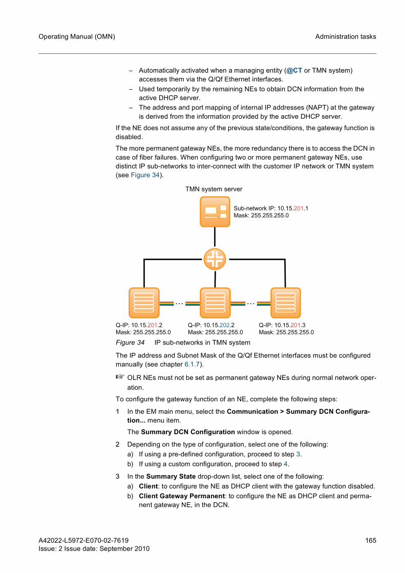
A42022-L5972-E070-02-7619Issue: 2 Issue date: September 2010
165
Operating Manual (OMN) Administration tasks
– Automatically activated when a managing entity (@CT or TMN system) accesses them via the Q/Qf Ethernet interfaces.
– Used temporarily by the remaining NEs to obtain DCN information from the active DHCP server.
– The address and port mapping of internal IP addresses (NAPT) at the gateway is derived from the information provided by the active DHCP server.
If the NE does not assume any of the previous state/conditions, the gateway function is disabled.
The more permanent gateway NEs, the more redundancy there is to access the DCN in case of fiber failures. When configuring two or more permanent gateway NEs, use distinct IP sub-networks to inter-connect with the customer IP network or TMN system (see Figure 34).
Figure 34 IP sub-networks in TMN system
The IP address and Subnet Mask of the Q/Qf Ethernet interfaces must be configured manually (see chapter 6.1.7).
☞ OLR NEs must not be set as permanent gateway NEs during normal network oper-ation.
To configure the gateway function of an NE, complete the following steps:
1 In the EM main menu, select the Communication > Summary DCN Configura-tion... menu item.
The Summary DCN Configuration window is opened.
2 Depending on the type of configuration, select one of the following:a) If using a pre-defined configuration, proceed to step 3.b) If using a custom configuration, proceed to step 4.
3 In the Summary State drop-down list, select one of the following:a) Client: to configure the NE as DHCP client with the gateway function disabled.b) Client Gateway Permanent: to configure the NE as DHCP client and perma-
nent gateway NE, in the DCN.
Q-IP: 10.15.202.2
Mask: 255.255.255.0
Q-IP: 10.15.201.2
Mask: 255.255.255.0
Q-IP: 10.15.201.3
Mask: 255.255.255.0
TMN system server
. . . . . .
Sub-network IP: 10.15.201.1
Mask: 255.255.255.0

166 A42022-L5972-E070-02-7619Issue: 2 Issue date: September 2010
Operating Manual (OMN)Administration tasks
c) Secondary Gateway Permanent: to configure the NE as a secondary DHCP server and permanent gateway NE, in the DCN.
d) Primary Gateway Permanent: to configure the NE as a primary DHCP server and permanent gateway NE, in the DCN.
If the new Summary State of the NE is set to Primary Gateway Permanent, ensure that the correct TransNet Archive is stored on the NE active bank (i.e., TransNet Archive with the new network configurations). If necessary download and swap the correct TransNet Archive, as described in chapter 6.4.6.
Proceed to step 8.
4 In the Summary State drop-down list, select Custom.
5 In the Settings area, select the NE role from the Role drop-down list:a) Primary: to set the NE as a primary DHCP server, in the DCN.b) Secondary: to set the NE as a secondary DHCP server, in the DCN.c) Client: to set the NE as a client DHCP, in the DCN.d) Inactive: to disable the DHCP role of the NE.
If the new DHCP Role of the NE is Primary, ensure that the correct TransNet Archive is stored on the NE active bank (i.e., TransNet Archive with the new network configurations). If necessary download and swap the correct TransNet Archive, as described in chapter 6.4.6.
6 In the Settings area, select the NE gateway function from the Gateway function status drop-down list:a) Disabled: to disable the gateway function of the NE.b) Permanent: to configure the NE as a permanent gateway NE, in the DCN.c) Temporary: to configure the NE as a temporary gateway NE, in the DCN.
Usually done automatically by the TMN system or @CT to configure the NE tem-porarily as a gateway.
d) Permanent Legacy Behaviour: configured automatically by the TMN system or @CT to configure the NE as permanent gateway NE in the DCN (with legacy behavior, i.e., previous version permanent gateway behavior) during an upgrade procedure from version 4.1 to version 4.20.
7 In the Settings area, select the bridge priority from the Bridge priority drop-down list:a) Priority Primary: to set the NE as the primary root node.b) Priority Secondary: to set the NE as the secondary root node.c) Priority Default: to keep the default settings based on the previous configura-
tions, i.e., according to the role configuration (e.g., an NE with primary role as a primary bridge priority).
8 If the NE is set as permanent gateway and is connected to a TL1 TMN system, select the Gateway for TL1 checkbox.
Click Apply to confirm the settings.
The NE gateway function is configured as desired.
g If the Gateway function status of the NE needs to be configured from Permanent Legacy Behaviour to Permanent (e.g., in case multi-domain DCN is required), the TMN system port numbers must be updated accordingly.

A42022-L5972-E070-02-7619Issue: 2 Issue date: September 2010
167
Operating Manual (OMN) Administration tasks
6.1.3 Configuring DHCP settingsNE detection and IP address assignment in the DCN is accomplished with the DHCP protocol.
The NEs in the DCN request a lease for a period of time from the DHCP server with the following parameters: • MAC address • NE name • Desired IP address (may be derived from previous lease and persistently stored)
The DHCP server stores the NE data persistently in an dynamic table for supervision of the discovered NEs. The DHCP server returns a lease grant with the assigned IP address, the IP address of the default gateway, and the NTP server addresses.
In order to provide redundancy, DHCP is supported by primary and secondary servers. The DCN addresses (DHCP pool) are a subset of the private address range between 172.16.0.0 and 172.31.255.255.
☞ The addresses from the configured pool(s) must not be used in other accessible networks (e.g., routers, TMN servers, FTP servers, etc.).
Configuring the NE DHCP roleTo configure the NE DHCP role, complete the following steps:
1 In the EM main menu, select the Communication > DHCP... menu item.
The DHCP Configuration window is opened.
2 Select a DHCP role in the Role drop-down list:a) Primary: to configure as the primary DHCP server.b) Secondary: to configure as the secondary DHCP server.c) Client: to configure as the DHCP client (default value).d) Inactive: to disable the DHCP role of the NE.
The STP priority should be configured according to the DHCP role, but can be set independently for special needs.
3 Click Apply to confirm the settings.
If the new DHCP Role of the NE is Primary, ensure that the correct TransNet Archive is stored on the NE active bank (i.e., TransNet Archive with the new network configurations). If necessary download and swap the correct TransNet Archive, as described in chapter 6.4.6.
The NE DHCP role is configured as desired.
Configuring the pool base address
☞ In networks with two or more domains (interconnected or not) connected to a single TMN system, it is required that different pool base addresses are set in each domain, i.e., each domain uses a specific IP range.
To configure the pool base address of the primary DHCP server, complete the following steps:
1 In the EM main menu, select the Communication > DHCP... menu item.
The DHCP Configuration window is opened.

168 A42022-L5972-E070-02-7619Issue: 2 Issue date: September 2010
Operating Manual (OMN)Administration tasks
2 Launch the EM of the secondary DHCP and set the DHCP role to client, as described in the Configuring the NE DHCP role procedure.
Click Apply to confirm the settings.
3 In the EM of the primary DHCP, configure the following settings:
Click Apply to confirm the settings.
☞ When the pool base address is changed a message “Operation failed: Failed to create static route. No traps will be received from the NE!!” is displayed in the System Log window for 1 hour.
4 In the EM of the secondary DHCP, reconfigure the DHCP role back to secondary as described in the Configuring the NE DHCP role procedure.
Click Apply to confirm the settings.
The NE pool base address of the primary DHCP server is configured as desired.
Adding a DCN domainWhen more than a single DCN domain is required, NEs that are located between two or three DCN domains are set as border-NEs.
In order to serve all the domains within the network (i.e., provide full connectivity between domains), new DCN domains have to be created via EM in each border-NE.
☞ In networks with two or more domains connected to a single TMN system, it is required that different pool base addresses are set in each domain, i.e., each domain uses a specific IP range.
To add a new DCN domain to a border-NE, complete the following steps:
1 In the EM main menu, select the Communication > DHCP... menu item.
The DHCP Configuration window is opened.
2 Click the Add... button.
The DHCP Configuration - Add window is opened.
3 Configure the following settings:
Click Add... to confirm the settings.
4 In the DHCP Configuration window, configure the following additional settings:
Base address[172.16.0.0 ... 172.31.255.0]:
Enter the range of IP addresses used by the DHCP server for IP address assignment.
It is recommended to use default value of 172.16.0.0/24 which allows up to 254 addresses.
Base port [10000 ... 13800]: Select the base port number used by the DHCP server for IP address assignment.
Base ports greater than 10800 are only used for @CT. Do not use base ports greater than 10800 for connections to TMN systems!
Pool Selector: Select the pool index of the new DCN domain.
Pool base address[172.16.0.0 ... 172.31.255.0]:
Enter the pool base address of the new DCN domain.
A42022-L5972-E070-02-7619Issue: 2 Issue date: September 2010
169
Operating Manual (OMN) Administration tasks
Click Apply to confirm the settings.
5 Repeat steps 1 to 3 to add a third DCN domain.
☞ It is required to define a new primary DHCP server and a new secondary DHCP server for the new and old domains repetitively.
A new DCN domain is added to the border-NE.
Deleting a DCN domain
☞ Deleting a DCN domain is only possible if no link direction is assigned to this DCN domain (i.e., DHCP pools do not contain assigned STP links).
If links are still assigned to the DCN domain to be deleted, EM will present a message box to reassign STP links. Click Yes to open DHCP Pool Assignment window and reassign the necessary STP links.
To delete a DCN domain from a border-NE, complete the following steps:
1 In the EM main menu, select the Communication > DHCP... menu item.
The DHCP Configuration window is opened.
2 Select the DCN domain entry to delete by clicking the far-left square of the table entry and click the Delete... button.
3 A confirmation window is displayed.
Click Yes to delete the DCN domain.
The selected DCN domain is deleted from the network.
6.1.4 Splitting a DCN domainThe number of NEs within one DCN domain is limited to 50 for TL1 management and 118 for SNMP management. Therefore, when a network grows it is necessary to split single DCN domains.
Before starting a split the DCN planning is required to avoid traffic loss and management loss. All the NEs receiving its SURPASS hiT 7300 DCN internal IP address from one DHCP server belong to the same DHCP domain. NEs belonging to two or three DHCP domains are called border-NEs.
For DCN planning the following information is required: • Network topology • NE names • Link direction IDs per NE • Assigned pool selector index per link direction
Role: Select the border-NE role for the new DCN domain.
Domain name: Enter the name for the new DCN domain.(can only be configured in a primary DHCP server)
Base port [10000 ... 13800]: Select the base port number for the new DCN domain.
Base ports greater than 10800 are only used for @CT. Do not use base ports greater than 10800 for connections to TMN systems!

170 A42022-L5972-E070-02-7619Issue: 2 Issue date: September 2010
Operating Manual (OMN)Administration tasks
• Distinct pool base address per DHCP domain
Figure 35 displays an example of a possible single DCN domain split.
Figure 35 DCN domain split example
PrerequisitesEnsure that the following information is obtained and taken into consideration before the procedure described below is performed: • A DCN planning of the new network must be available. • Border-NEs and link assignment to the pool selector index. • New management access points (i.e., gateways) to the new network. • The initial primary DHCP server is assigned to the new domain as primary DHCP
server. • The initial secondary DHCP server is assigned to the remaining domain as second-
ary DHCP server.
To split a DCN domain, complete the following steps:
1 Open the EM of the primary DHCP server.
2 In the EM main menu, select the Communication > STP... menu item.
The STP Configuration window is opened.
3 Take note of the current Path cost [0 ... 65535] value and then unassign the link direction of the future border-NEs by configuring the Path cost [0 ... 65535] to 0 ((e.g., in Figure 35 NEs #2 and #5).
Click Apply to confirm the settings.
The initial DCN domain is split and a new DCN domain is created.
All DCN traffic of the affected links is interrupted! However, optical traffic is not affected.
Primary DHCP server
Secondary DHCP server
Initial domain
172.16.1.0
Port range: 100xx
NE #1
NE #7
NE #3
NE #5NE #4
NE #2
NE #6
NE #8
Split domain A
172.16.1.0
Port range: 100xx
Split domain B
172.16.2.0
Port range: 102xx
NE #1
NE #7
NE #5NE #4
NE #2
NE #8
border-NE
border-NE+
NE #3
NE #5
NE #2
NE #6
border-NE
border-NE

A42022-L5972-E070-02-7619Issue: 2 Issue date: September 2010
171
Operating Manual (OMN) Administration tasks
4 In the DHCP Configuration window of the primary DHCP server of the new domain (NE #3), configure the following settings for the new split domain B:
Click Apply to confirm the settings.
☞ When the pool base address is changed a message “Operation failed: Failed to create static route. No traps will be received from the NE!!” is displayed in the System Log window for 1 hour.
Please disconnect all NEs of the new domain from your TMN system and wait 10 minutes before connecting the NEs with the new port.
5 In the primary DHCP server EM of the new domain (NE #3), select the Communi-cation > Reachable Systems... menu item.
The Reachable Systems window is opened.
6 The NEs where the DHCP lease state is “Lease Expired” must be deleted at the primary DHCP server of the new domain B
Repeat this step in the secondary DHCP server of domain A.
7 Add a second domain in the border-NE(s) by configuring them according to the new DCN plan and as described in the Adding a DCN domain procedure.
The border-NE #2 must be configured as primary DHCP server for domain A and as secondary DHCP server for domain B. The NE #5 must be configured as DHCP client for both domains.
8 At the border-NEs (NE #2 and NE #5) the links that are connected to the new domain B must be assigned to the new DHCP pool.
In the DHCP Pool Assignment window of all border-NEs, set the Pool selector index drop-down list to 2.
Click Apply to confirm the settings.
9 The STP path cost values of the previously deactivated links in step 3 must be now reset to the old values.
Re-open the STP Configuration window of the new primary DHCP server and con-figure the Path cost [0 ... 65535] of the deactivated links with the old values.
10 In the Reachable Systems window, ensure that the border-NE(s) are visible. The lease state must be "Granted".
Repeat this step in the secondary DHCP server EM.
11 Configure the STP settings according to the rules and procedures described in chapter 6.1.6.
Domain name: Enter the name of the DCN domain to which the primary DHCP server belongs to.
Base address[172.16.0.0 ... 172.31.255.0]:
Enter the pool base address of the DCN domain to which the primary DHCP server belongs to.
Base port [10000 ... 13800]: Select the base port number of the DCN domain to which the primary DHCP server belongs to.
Base ports greater than 10800 are only used for @CT. Do not use base ports greater than 10800 for connections to TMN systems!

172 A42022-L5972-E070-02-7619Issue: 2 Issue date: September 2010
Operating Manual (OMN)Administration tasks
The DCN domain is split.
☞ For redundant access to the domains, new connections from some NEs to the man-agement system may be required.
6.1.5 Merging DCN domainsMerging DCN domains (i.e., physically interconnect domains) comprises two distinct case scenarios: • Merge domains but keeping them all as separate DCN domains. • Merge domains to create a single DCN domain within the network.
Before starting a merge the DCN planning is required to avoid traffic loss and manage-ment loss. All the NEs receiving its SURPASS hiT 7300 DCN internal IP address from one DHCP server belong to the same DHCP domain. NEs belonging to two or three DHCP domains are called border-NEs.
For DCN planning the following information is required: • Network topology • NE names • Link direction IDs per NE • Assigned pool selector index per link direction • Pool base address list of all the existing DCN domains
Merging domains in multiple DCN domains configurationThis procedure should be executed only when a merge of two domains is required but all the distinct DCN domains are not merged (i.e., the final network will contain multiple DCN domains).
Figure 36 displays an example of a possible merge (i.e., physical interconnection) of two DCN domains.

A42022-L5972-E070-02-7619Issue: 2 Issue date: September 2010
173
Operating Manual (OMN) Administration tasks
Figure 36 Merge of two domains maintaining the two original DCN domains
Ensure that the following information is obtained and taken into consideration before the procedure described below is performed: • A DCN planning of the new network must be available. • Border-NEs and link assignment to the pool selector index. • New management access points (i.e., gateways) to the new network.
☞ The two domains must use different pool base addresses and different pool base ports. If the initial configuration is using the same pool base addresses and ports one domain must be changed before initiating the following procedure.
To merge domains in multiple DCN domains configuration, complete the following steps:
1 Open the EMs of the primary DHCP servers of both domains and perform the fol-lowing steps in both of them.
2 Download the new TransNet Archive file, as described in chapter 6.4.6.
3 Distribute and swap all the new NCF files, as described in chapter 6.4.8.
4 Physically install all the required hardware, with the support of the Installation and Test Manual (ITMN).
5 Install all the necessary cabling, as described in the Interconnect, Configuration and Mechanical Assembly (ICMA).
6 Add a second domain to the border-NE(s) by configuring them according to the new DCN plan and as described in the Adding a DCN domain procedure.
7 Configure the STP settings according to the rules and procedures described in chapter 6.1.6.
8 The new (i.e., not assigned) links must be assigned now to the correspondent DCN domains.
Primary DHCP server
Secondary DHCP server
Domain A
172.16.1.0
Port range: 100xx
Domain B
172.16.2.0
Port range: 102xx
Merged domain A
172.16.1.0
Port range: 100xx
Merged domain B
172.16.2.0
Port range: 102xx
NE #1
NE #7
NE #4
NE #8
NE #3
NE #5
NE #2
NE #6
bord
er-N
E
NE #1
NE #7
NE #3
NE #5NE #4
NE #2
NE #6
NE #8
bord
er-N
E

174 A42022-L5972-E070-02-7619Issue: 2 Issue date: September 2010
Operating Manual (OMN)Administration tasks
In the DHCP Pool Assignment window, set the Pool selector index according to the new DCN plan (i.e., each new link will be assigned to a single-domain).
Click Apply to confirm the settings.
Repeat this step for all the NEs which will have new link directions (e.g., in Figure 36 NEs #1, #2, #4, #5, and #8).
9 In the EM main menu of all the DHCP servers, select the Communication > Reach-able Systems... menu item.
The Reachable Systems window is opened.
10 Ensure that the border-NE(s) are visible in all the DHCP servers. The DHCP Lease State must be "Granted".
The merge of domains in multiple DCN domains configuration is completed.
Merging domains to a single DCN domain configurationFigure 37 displays an example of a possible merge (i.e., physical interconnection) of two domains to create a single DCN domain.
Figure 37 Merge of two domains to create a single DCN domain
To merge domains to a single DCN domain configuration, complete the following steps:
1 Open the EMs of the primary DHCP servers of both domains and perform the fol-lowing steps in both of them.
2 Download the new TransNet Archive file, as described in chapter 6.4.6.
3 Distribute and swap all the new NCF files, as described in chapter 6.4.8.
4 Physically install all the required hardware, with the support of the Installation and Test Manual (ITMN).
Primary DHCP server
Secondary DHCP server
Domain A
172.16.1.0
Port range: 100xx
Domain B
172.16.2.0
Port range: 102xx
Merged domain
172.16.1.0
Port range: 100xx
NE #1
NE #7
NE #4
NE #8
NE #3
NE #5
NE #2
NE #6
NE #1
NE #7
NE #3
NE #5NE #4
NE #2
NE #6
NE #8

A42022-L5972-E070-02-7619Issue: 2 Issue date: September 2010
175
Operating Manual (OMN) Administration tasks
5 Install all the necessary cabling, as described in the Interconnect, Configuration and Mechanical Assembly (ICMA).
6 In a single-domain only one primary and only one secondary DHCP server is allowed. According to your network plan reconfigure the remaining primary/second-ary DHCP servers, as described in the Configuring the NE DHCP role procedure by set them to DHCP Client (e.g., in Figure 37 NEs #1 and #2 are set to client).
7 According to the new DCN plan, align the pool base address and port ranges of all the domains, as described in the Configuring the pool base address procedure (e.g., in Figure 37 NE #3).
8 Configure the STP settings according to the rules and procedures described in chapter 6.1.6.
9 The new (i.e., not assigned) links must be assigned now to the new single DCN domain.
In the DHCP Pool Assignment window, set the Pool selector index drop-down list of each new link to 1.
Click Apply to confirm the settings.
Repeat this step for all the NEs which will have new link directions (e.g., in Figure 36 NEs #1, #2, #4, #5, and #8).
10 In the EM main menu of all the DHCP servers, select the Communication > Reach-able Systems... menu item.
The Reachable Systems window is opened.
11 Ensure that all the NEs are visible in all the DHCP servers. The DHCP lease state must be "Granted".
The NEs corresponding to any non-existing domain and DHCP lease state "Expired" can be deleted.
The merge of domains to a single DCN domain configuration is completed.
6.1.6 Configuring STPThe STP is supported in order to maintain a loop-free topology of the DCN.
In a single-domain, the maximum possible STP tree deepness is 19. This value must be configured with the STP diameter parameter. The diameter value is the worst case value for the DCN domain. By default, the STP status is automatically enabled in: • NEs configured as primary/secondary DHCP server by using the DCN state pre-
configuration. • ONNs with nodal degree higher than 2.
Per each domain the STP should be enabled according to the rules described below (for examples see Figure 38):
1. In case the NE is configured as a DHCP server (primary/secondary), the STP status is automatically enabled and the bridge priority has to be configured according to the DHCP server role (client, secondary or primary).
2. If an ONN has a nodal degree higher than 2, the STP status is automatically enabled.

176 A42022-L5972-E070-02-7619Issue: 2 Issue date: September 2010
Operating Manual (OMN)Administration tasks
3. If two NEs in a single domain are connected by their Q External interfaces (address 255.255.255.255) regardless of the nodal degree STP must also be enabled (even for OLRs). Such NEs must be manually set to enabled via EM.
4. In a ring (or mesh) topology, at least two of the related NEs must have the STP status enabled (preferably ONNs, although an OLR can also be used). For these NEs the STP status must be set to enabled manually via EM.
5. The STP status must stay disabled for all the remaining NEs in a DCN including OLR (by default automatically set to disabled).
Figure 38 STP configuration in a single-domain meshed network
In multi-domain networks border-NEs have to be configured according to the following rules (also see Figure 39):
1. If the border-NE has nodal degree 1 or 2 for a specific domain, the STP of that domain in the border-NE has to be disabled.
2. If the border-NE has nodal degree greater than 2 for a specific domain, the STP of that domain in the border-NE has to be enabled.
Rule 1
Rule 4
Rule 4Rule 2
Q interface
Rule 3
Primary
DHCP Server
Rule 2

A42022-L5972-E070-02-7619Issue: 2 Issue date: September 2010
177
Operating Manual (OMN) Administration tasks
Figure 39 STP configuration in border-NEs
The STP diameter depends on the network topology/diagram but it always has to be less, or equal to the maximum number of bridges (19).
The STP diameter is the maximum number of hops (or number of NEs crossed including the source and destination) between any two bridges in the DCN network. The worst case scenario can be found by searching the longest possible path between any two bridges in the network without crossing the same bridge more than once. It has to be considered, that no two bridges can communicate through more than <x> hops, where <x> = Nmax hops = STP diameter.
The default value for the STP diameter is set to 7. If in a given network Nmax hops turns out to be higher than 7 the value for STP diameter has to be adapted accordingly for all NE where STP is set to active. Note: Higher values for STP diameter may cause longer intervals for STP conversion.
Networks that exceed the maximum supported diameter should be partitioned in distinct DCN domains.
The STP bridge priority must be set accordingly to the DHCP server-role (as already stated above).
Disabling STPTo disable STP, complete the following steps:
1 In the EM main menu, select the Communication > DHCP... menu item.
The DHCP Configuration window is opened.
2 In the clear the STP Status checkbox to disable the STP.
Click Apply to confirm the settings.
The STP is disabled.
Enabling STP
☞ The STP bridge priority can also be set while configuring the gateway function.
To enable STP, complete the following steps:
1 In the EM main menu, select the Communication > DHCP... menu item.
The DHCP Configuration window is opened.
Internal
domain #1
Internal
domain #2
Border-NE
Domain #2
on border-NE
Domain #1
on border-NE
Rule 1 Rule 2

178 A42022-L5972-E070-02-7619Issue: 2 Issue date: September 2010
Operating Manual (OMN)Administration tasks
2 In the table, select the STP Status checkbox to enable the STP.
On border-NEs there will be 2 or more entries each corresponding to the domain to which the border-NE belongs to.
3 Configure the STP diameter in the STP Diameter field.
4 Select a priority for the NE in the STP Bridge priority drop-down list as follows:a) Priority Primary: for an NE configured as a primary DHCP server (priority of
1000H).b) Priority Secondary: for an NE configured as a secondary DHCP server (priority
of 2000H).c) Priority Default: for an NE not configured as DHCP server (priority of 8000H).
Click Apply to confirm the settings.
5 In the EM main menu, select the Communication > STP... menu item.
The STP Configuration window is opened.
6 The list displays the transmission directions between the bridges.
The path cost is used to optimize the STP according to the specific network topol-ogy. It is strongly recommended that only users with profound STP expertise may modify these settings. A wrong configuration may cause malfunction or breakdown of the DCN.
Configure the Path cost [0 ... 65535] for each entry in the list with a value between 1 and 65535.
Click Apply to confirm the settings.
☞ When configuring the STP path cost to a value of 0 (zero), the DCN will be disabled for that link direction.
The STP is enabled.
6.1.7 Configuring Q and QF interfacesEach NE provides two Ethernet interfaces, Qf and Q. The Qf and Q interfaces are avail-able in every NE controller card for a local and/or remote management of the NE.
Qf interfaceThe Qf interface is enabled by default to access the NE locally via @CT. A default IP address is assigned to this interface (range between 192.168.126.1 (default) and 192.168.127.254), which is based on the DCN internal bridge.
Any client connected to this interface and configured as a DHCP client is automatically assigned with an IP address of the same range (the NE acts as DHCP/DNS server for this interface). Therefore, the @CT can be downloaded and started by using the URL "http://LocalQF." in a web browser.
Additionally the Qf interface can be used for external access, i.e., to connect the NE to the customer IP network (e.g., router, TMN server, FTP server or NTP server) when the Q interface is connected to the internal DCN.
Q interfaceThe Q interface is used to connect the NE/DCN to the customer IP network (e.g., router, TMN server, FTP server or NTP server) using an address between 0.0.0.0 and 224.0.0.0.

A42022-L5972-E070-02-7619Issue: 2 Issue date: September 2010
179
Operating Manual (OMN) Administration tasks
The Q interface may alternatively be used to communicate with the internal DCN network by using the nominal address 255.255.255.255, i.e., the interface provides con-nectivity to the DCN internal bridge. This can be used to interconnect NEs directly via the Q interface as implemented by the optical links.
In this case the Qf interface can be used to connect the NE to the customer IP network by configuring an address from range 0.0.0.0 to 224.0.0.0. A cross-over cable or an external switch with cross-over capability might be necessary. A switch is always required when a TMN system and an @CT are both using the Qf interface at the same time.
Reserved IP addressesThe NEs/DCN use specific IP address ranges for internal communication purposes. Therefore, the Q/Qf interfaces or any device in the customer network cannot use the IP addresses listed in Table 37.
Configuring the Q interfacesTo configure the Q interfaces, complete the following steps:
1 In the EM main menu, select the Communication > Interfaces... menu item.
The Interfaces window is opened.
2 The default value 0.0.0.0 indicates that the interfaces are inactive.
Configure the following settings in the Q interfaces areas:
Assigned IP address range Remarks
169.254.0.0 - 169.254.255.255(prefix subnet length = 16)
Used for internal communication between the NE controller card and remaining cards.
172.16.0.0 - 172.31.255.255(prefix subnet length = 24)
Used by the DHCP server for IP assignment to NEs in DCN domain.
Note that only one subnet, with prefix length 24, in the specified range is used per domain (default is 172.16.1.0/24). On a border-NE more than one subnet is configured.
192.168.126.0 - 192.168.127.252(prefix subnet length = 30)
Used for local laptop access to the NE via Qf inter-face.
Table 37 IP address ranges used within SURPASS hiT 7300

180 A42022-L5972-E070-02-7619Issue: 2 Issue date: September 2010
Operating Manual (OMN)Administration tasks
Qf local interface
IP address/Subnet mask: Can be enabled or disabled by clicking the Enable or Disable buttons.
Click the Enable button to enable the Qf local interface with the default IP address 192.168.126.1 and SubNet Mask 255.255.255.252.
Click the Disable button to disable the Qf local interface with the default IP address 0.0.0.0.
This IP address is also assessable via the “LocalQf.“ host name for simpler access via @CT.
Q external interface
IP address/Subnet mask: Enter the IP address/Subnet Mask of the customer network to use for external access, or enter 255.255.255.255/255.255.255.255 to communicate with the internal DCN.
Click the Set As Bridge button to configure the Q external interface as a bridge and automati-cally set the IP address/Subnet Mask to 255.255.255.255/255.255.255.0.
When configured as bridge, use the DHCP Pool Assignment... button to configure the pool assignment values.
Traffic Shaping: Select the desired TCP traffic shaping rate.
Allow SNMP management protocol at this interface:
Select/Clear the checkbox to enable/disable the SNMP management interface. When disabled all the respective UDP ports are closed.
Allow TL1 management protocol at this interface:
Select/Clear the checkbox to enable/disable the TL1 management interface. When disabled all the respective Transmission Control Protocol (TCP) ports are closed.
Qf external interface
IP address/Subnet mask: Can only be configured when Q External Inter-face is connected to the internal DCN, which enables the usage of the Qf interface for external access. Enter an IP address/Subnet Mask of the customer network to use for external access.
Traffic Shaping: Select the desired TCP traffic shaping rate.
Allow SNMP management protocol at this interface:
Select/Clear the checkbox to enable/disable the SNMP management interface. When disabled all the respective UDP ports are closed.

A42022-L5972-E070-02-7619Issue: 2 Issue date: September 2010
181
Operating Manual (OMN) Administration tasks
g If the Q external interface is configured as a bridge and is later used to com-municate with a TNM system, the Qf external interface must be reset to the default value (0.0.0.0) before reconfiguring the Q external interface.
Click Apply to confirm the settings.
The Q interfaces are configured as desired.
6.1.8 Configuring static routesA route entry is used for IP packet forwarding, with an interface and gateway to use in a packet/destination address, based on the next hop. The routing entry with the closest match (longest prefix match) is used. When there are two route entries to the same des-tination network/IP address via two distinct hops (e.g., routers or gateway NEs), the first route entry or the entry with the lowest index is used.
The primary purpose of the route table is to define routes from temporary or permanent gateway NEs to routers, TMN systems or FTP servers in the customer IP network: • Static routes must be manually created from a permanent gateway NE when the
customer IP network has a router between the DCN and the TMN system. Other-wise, no static route is necessary (i.e., the TMN system and the permanent gateway NE are in the same IP network).
• When accessing a specific NE in the DCN via a gateway NE (permanent or tempo-rary), a route entry to the TMN system/EM (destination) is automatically created in the specific NE via that gateway NE (next hop).
• Route entries can also be used for reaching SNMP trap receivers via a permanent gateway NE.
For external destinations, the use of a symbolic name (DNS) is not possible (only net-work/IP addresses).
Figure 40 shows an example of a possible managed SURPASS hiT 7300 network and all the possible routes between all the available devices/components.
Allow TL1 management protocol at this interface:
Select/Clear the checkbox to enable/disable the TL1 management interface. When disabled all the respective TCP ports are closed.
Qf external interface

182 A42022-L5972-E070-02-7619Issue: 2 Issue date: September 2010
Operating Manual (OMN)Administration tasks
Figure 40 Static routes in a SURPASS hiT 7300 network
A maximum of 16 entries is allowed.
To configure a static route, complete the following steps:
1 In the EM main menu, select the Communication > IP Static Routing... menu item.
The IP Static Routing Configuration window is opened.
2 Click the Add... button.
The IP Static Routing - Add window is opened.
3 Select the static route type in the IP Route type drop-down list. If creating a static route to a permanent gateway or a TMN system it is advisable to select the “Default” route type.
Configure the following settings according to the route type selection (Subnet mask and IP Route type are configured by default if one of the pre-defined route types are used):
Network address: Enter the destination DNS/IP address.
The static routes on permanent gateway NEs to TNMS must be net routes (i.e., not host routes).
Subnet mask: Enter the destination DNS/Subnet Mask (only if “Custom” route type is used).
Next hop (e.g. router): Enter the DNS/IP address of the next hop.
TMN system server
Q-IP: 10.15.1.2
Q-Mask: 255.255.255.0
Route IP: 10.15.201.0
Mask: 255.255.255.0
Next hop: 10.15.1.1
Sub-network IP: 10.15.201.1
Mask: 255.255.255.0
Q-IP: 10.15.2.2
Q-Mask: 255.255.255.0
Route IP: 10.15.202.0
Mask: 255.255.255.0
Next hop: 10.15.2.1
Q-IP: 10.15.3.2
Q-Mask: 255.255.255.0
Route IP: 10.15.201.0
Mask: 255.255.255.0
Next hop: 10.15.3.1
IP: 10.15.1.1
Mask: 255.255.255.0
IP: 10.15.2.1
Mask: 255.255.255.0
IP: 10.15.201.2
Mask: 255.255.255.0
IP: 10.15.202.2
Mask: 255.255.255.0
IP: 10.15.3.1
Mask: 255.255.255.0
. . . . . .

A42022-L5972-E070-02-7619Issue: 2 Issue date: September 2010
183
Operating Manual (OMN) Administration tasks
Click Apply to confirm the settings.
The static route is created/configured as desired.
6.1.9 Configuring reachable systemsThe list of reachable systems is presented by permanent and temporary gateway NEs detected by the active DHCP server.
The initial NE Name after start-up is derived from the MAC address of the Ethernet inter-face.
After NE commissioning, the initial NE name can be modified by the user (must ensure unique NE Name).
Deleting a reachable systemAny primary or secondary DHCP server that is removed from the network (i.e., is no longer reachable by any NE within the DCN) cannot be deleted from the reachable systems table.
The removed NE is displayed in the reachable systems table with "*ame" in place of the complete name "name" and a TNEF alarm is raised. To clear the TNEF alarm, please refer to the Troubleshooting Manual (TSMN).
By rebooting the primary and/or secondary DHCP server the removed NE will no longer be displayed as "*ame". The removed NE is displayed as (*) and no TNEF alarms are displayed.
☞ A reachable system can only be deleted if it’s lease state is “Lease Expired”.
To delete a reachable system (which is not a primary or secondary DHCP server) of an NE, complete the following steps:
1 In the EM main menu, select the Communication > Reachable Systems... menu item.
The Reachable Systems window is opened.
2 Click the Delete button.
A confirmation window is opened. Click Yes to delete the reachable system.
3 Close the Reachable Systems window.
The reachable system is deleted.
Viewing reachable systemsTo view the reachable systems of an NE, complete the following steps:
1 In the EM main menu, select the Communication > Reachable Systems... menu item, in the EM main menu.
The Reachable Systems window is opened.
2 Use the Filter settings to filter the displayed NEs according to a specific DCN domain.
IP Route type: Select the desired IP route type (only if “Custom” route type is used).

184 A42022-L5972-E070-02-7619Issue: 2 Issue date: September 2010
Operating Manual (OMN)Administration tasks
The ”Lease Granted” state means the NE is reachable and the ”Lease Expired” state means the NE is temporarily unavailable. Permanently unavailable NEs can be removed from the list.
The list of discovered NEs in the DCN is displayed.
Viewing reachable system detailsTo view the reachable systems of an NE, complete the following steps:
1 In the EM main menu, select the Communication > Reachable Systems... menu item.
The Reachable Systems window is opened.
The ”Lease Granted” state means the NE is reachable and the ”Lease Expired” state means the NE is temporarily unavailable. Permanently unavailable NEs can be removed from the list.
2 Select the desired reachable system from the list and click Details....The Reachable Systems - Details window is opened.
The details of the selected reachable system are displayed.
6.1.10 Viewing SNMP trap forwarding entries☞ SNMP traps management is only available to users with administration privileges
(i.e., which belong to the Administration user group)
Each TMN system registers for SNMP traps while establishing the connection with the NE. The SNMP trap forwarding entries allow the TMN system to be notified of alarms, NE modifications, etc.
To view the SNMP trap forwarding entries of the NE, complete the following steps:
1 In the EM main menu, select the Communication > SNMP Traps menu item.
The SNMP Traps Management window is opened.
2 Use the table ordering settings per field to identify/find a specific entry or entries in the list.
The SNMP trap forwarding entries of the NE are displayed.
6.1.11 Viewing DCN diagnostic dataThe DCN Diagnostics provide the following data concerning the DCN: • STP status/Bridge state • STP topology data (only from primary or secondary DHCP servers) • Internal and external IP addresses • IP network statistics • IP connections • Virtual Local Area Network (VLAN) configuration • Priority configuration of internal Local Area Network (LAN) • User channel configuration • List of active/blocked ports with direction ID

A42022-L5972-E070-02-7619Issue: 2 Issue date: September 2010
185
Operating Manual (OMN) Administration tasks
To view the DCN diagnostic data, complete the following steps:
1 In the EM main menu, select the Communication > Diagnostics Upload... menu item.
The Network Element - FTP Upload - DCN Diagnostic Data window is opened.
2 Depending on the desired FTP server, select one of the following radio buttons:a) EM internal server: to use the EM internal FTP server.b) External server: to use an external FTP server.
3 The radio button selected in step 2 determines which fields are displayed on the window. Configure the applicable fields as explained below:
Click Upload to upload the files.
The upload status is displayed in a progress bar in the Progress area located at the bottom of the window.
Once the upload is complete, a dialog box is displayed to view the log.
4 Click Yes to view the DCN diagnostic data in the “DCN Diagnostics” window.
The DCN diagnostic data is displayed.
6.2 Configuration managementThe following sub-chapters describe configuration management tasks.
6.2.1 Adding and removing shelvesThe add and remove shelves procedure is required whenever a shelf is physically added/removed to/from an NE.
Adding shelvesTo add a shelf via EM, the user must consult the Customer commissioning plan to assign the correct shelf IDs to the corresponding shelves. It is mandatory that the shelf IDs between the EM configuration, and the physical installation match.
Before configuring the new shelf in the EM the ILAN connections should be established, as described in the Installation and Test Manual (ITMN). After the installation of the ILAN connections, the ILAN1 connector of the first shelf and the ILAN2 connector of the last shelf will not be connected as such the first ILAN port of the first shelf and the second ILAN port of the last shelf will have the ILANF alarm raised. This alarms should be
Server IP address: Enter the remote FTP server IP address.
Transfer protocol: Select the protocol to upload the file.
Gateway host name: Enter the NE Name of the permanent gateway NE where the file is stored.
User name: Enter the account user name of the remote server.
Password: Enter the account password of the remote server.
Target folder: Click this button to browse and define the local path for the file.
Target file name: Enter the name for the file.(Please note that the file name must not have spaces).

186 A42022-L5972-E070-02-7619Issue: 2 Issue date: September 2010
Operating Manual (OMN)Administration tasks
masked, alternatively the user can disable those ILAN ports. This is not advisable because the disabling of the wrong ILAN can lead to lost remote connection.
g The disabling of one, or both, internal LAN connectors of a shelf may lead to a loss of connectivity between all shelves of the NE, that are interconnected via the internal LAN connectors.
In addition, the NE might cease to be remotely reachable if the management data stream (e.g., GCC0) is served by a shelf which is no longer connected to the CCxP-x controller card and no redundant DCN access exists among the remaining shelves.
Ensure that a redundant DCN access is available, or the loss of connectivity is sus-tainable and can be recovered. To regain remote connectivity to the shelf the user must travel to the site to enable the internal LAN connector(s) and cold start the CCxP-x shelf controller card.
Each NE hosts a default shelf with ID number “1” housing the NE controller card that cannot be modified. After initial configuration, no shelf ID modifications are possible. The ONN and SON NEs support a maximum of 30 standard shelves, and the SONF NE can hold up to 8 flatpack shelves.
☞ The fields Bay [0 ... 8] and Shelf in Bay [0... 99] are only editable when the NE Commissioning Status is not set to Commissioned.
To add a shelf, complete the following steps:
1 Physically install the shelf on the rack of the NE, as described in the Installation and Test Manual (ITMN).
2 Install all the necessary cabling, as described in the Interconnect, Configuration and Mechanical Assembly (ICMA).
3 In the EM main menu, select the Configuration > NE > Shelves... menu item.
The Shelves Configuration window is opened.
4 To add a new shelf click the Add... button.
The Shelves - Add window is opened.
5 According to Customer commissioning plan configure the following settings:
Click Add to add the shelf.
6 In the Shelves Configuration window, configure the following settings according to Customer commissioning plan:
Click Apply to confirm the settings.
Repeat steps 1 to 6 for all required shelves.
7 In the EM main menu, select the Alarms > Suppression... menu item.
Shelf ID [2 ... 30]: Enter the shelf ID number, for ONN/SON.
Shelf ID [2 ... 8]: Enter the shelf ID number, for SONF.
Location: Enter the shelf location in rack.
Bay [0 ... 8]: Enter the number of the rack in which the shelf is physically installed.
Shelf in Bay [0 ... 99]: Enter the number of the physical bay location of the shelf within the rack.

A42022-L5972-E070-02-7619Issue: 2 Issue date: September 2010
187
Operating Manual (OMN) Administration tasks
The Alarm Suppression window is opened.
8 In the Filter settings insert ILANF as the alarm name and click Enable.
The ILANF alarms for each shelf appear in the alarm list.
9 In the Notification Suppression column, select the checkbox for the first ILAN port of the first shelf and for the second ILAN port of the last shelf.
Click Apply.
The new shelf is added to the NE.
Removing shelvesTo remove a shelf, complete the following steps:
1 In the EM main menu, select the Configuration > NE > Shelves... menu item.
The Shelves Configuration window is opened.
2 Select the shelf to be removed from the list and click Delete.
3 A warning message, concerning traffic interruption is displayed.
Click Continue to remove the shelf.
4 Remove all the cabling from the shelf and physically remove the shelf from the rack, as described in the Installation and Test Manual (ITMN).
Repeat steps 1 to 4 for all required shelves.
5 In the EM main menu, select the Alarms > Suppression... menu item.
The Alarm Notification Suppression window is opened.
6 In the Filter settings insert ILANF as the alarm name and click Enable.
The ILANF arms for each shelf appear in the alarm list.
7 In the Notification Suppression column, select the checkbox for the first ILAN port of the first shelf and for the second ILAN port of the last shelf.
Click Apply.
The shelf is removed from the NE.
6.2.2 Adding and removing cardsThe add and remove cards procedure is only applicable for SON and SONF NEs. In all other types of NEs, i.e., OLRs and ONNs, this procedure is automatic via NCF or manual if the service provisioning via NMS function is enabled.
g To install a protection transponder in a system prepared for protection (upgrading system protection), i.e., both the O03CP-1 card and working transponder are installed, please refer to chapter 4.2.4.
Adding a new cardAccording to the chosen configuration, it is possible to equip a SON/SONF with the fol-lowing card types: • All the defined types of controller cards. • LASB-1 and LAMP-1 amplifier cards. • LIFB-1 Booster-less line interface • F04MDN-1, F04MDU-1, F08SB-1, F16SB-1, F40-1, F40V-1, and F80MDI-1.

188 A42022-L5972-E070-02-7619Issue: 2 Issue date: September 2010
Operating Manual (OMN)Administration tasks
• O08VA-1 variable optical attenuator card. • CFSU-1 flow sensor card. • DCM cards using FBG and the D0170DCF card. • All the defined types of transponder cards. • OPMDC-2 optical PMD compensation card. • O03CP-1 optical channel protection card. • O02CSP-1 dual protection card.
In a SON/SONF NE all of the above cards can be added using the plug and play func-tionality.
In an ONN/OLR the core cards should not be added or removed even in service provi-sioning via NMS mode. According to the chosen configuration, it is possible to equip an ONN in the service provisioning via NMS mode with the following card types: • F04MDN-1, F04MDU-1 filter cards. • O08VA-1 variable optical attenuator card. • CFSU-1 flow sensor card. • All the defined types of transponder cards. • OPMDC-2 optical PMD compensation card. • O03CP-1 optical channel protection card. • O02CSP-1 dual protection card.
In an ONN NE all of the above cards can be added using the plug and play functionality.
☞ In an ONN NE an F04MDN-1 or an F04MDU-1 filter can only be added or removed in an ONN-I or an ONN-T and if its not next to the top of the mux tree (e.g. EOL 20 and 32).
☞ In an ONN or OLR NE a CFSU-1 card can only be added or removed if it is not supervising a DCM tray.
To add a card, complete the following steps:
1 Verify if the shelf slot where the new card will be installed is equipped as empty or empty-auto.
2 Physically install the card on the required slot of the shelf/NE, as described in the Installation and Test Manual (ITMN).
3 Install all the necessary cabling, as described in the Interconnect, Configuration and Mechanical Assembly (ICMA).
4 Depending on the specific situation select one of the following:
a) If the shelf slot where the card was inserted was empty-auto proceed to step 7.b) If the shelf slot where the card was inserted was empty in a SON/SONF NE
proceed to step 5.
5 In the EM Shelf View window, select the shelf where the card was installed by clicking the correspondent shelf tab (e.g., Shelf 001).
6 Right-click the slot replica (e.g., 001) where the card was installed, and select the correspondent card name, and if applicable, the card subtype and line direction from the displayed list.
☞ The definition of the card subtype is mandatory for all filter cards and for the I01T40G-1, I01R40G-1, and I04T40G-1 cards.

A42022-L5972-E070-02-7619Issue: 2 Issue date: September 2010
189
Operating Manual (OMN) Administration tasks
For the remaining cards the subtype definition is optional. Configuring it to “No Subtype” allows the use of other cards to be used as spared whenever possible (e.g., an I01T10G-1 LH can be used as spare for a I01T10G-1 Regio).
While EM acquires all the necessary data from the card, the card replica is displayed in orange (i.e., not ready to carry traffic). The card will be ready to carry traffic when the card replica is displayed in yellow.
7 For F40(V) cards select the desired card mode from the Card Mode drop-down list.
The new card is added.
g Before adding a new card, wait until the last command is acknowledged (can take up to 90 seconds) from the NE (i.e., the "no pending jobs" symbol is displayed at the right-end of the status bar).
☞ The equivalent TL1 command for adding a new card is listed below.
For additional information, please refer to the TL1 Command and Message List (CML) document.
Removing a cardThe card to be removed should not be included in a protection group (i.e., transponders and optical channel protection cards). Delete any protection group that includes this card, as described in chapter 4.2.2.
The card to be removed should not be included in a cross connection (i.e., transponders and filters). Delete any cross connection that includes this card, as described in chapter 4.3.3.
To remove a card, complete the following steps:
1 In the EM Shelf View window, select the shelf where the card to remove is installed by clicking the correspondent shelf tab (e.g., Shelf 001).
2 Right-click the slot replica (e.g., 001) where the card is installed, and select Empty from the displayed list.
The card is removed from EM Shelf View window.
3 Remove all the cabling from the card and physically remove the card from slot of the shelf/NE, as described in the Installation and Test Manual (ITMN).
The card is removed.
g Before removing another card, wait until the last command is acknowledged (can take up to 90 seconds) from the NE (i.e., the "no pending jobs" symbol is displayed at the right-end of the status bar).
☞ The equivalent TL1 command for deleting a is listed below.
Removing a card via TL1 will always place the slot into empty-auto.
For additional information, please refer to the TL1 Command and Message List (CML) document.
ENT-EQPT
DLT-EQPT

190 A42022-L5972-E070-02-7619Issue: 2 Issue date: September 2010
Operating Manual (OMN)Administration tasks
6.2.3 Changing NE stateThe NE state can be changed to one of the following modes: • Maintenance: used to indicate that it is safe to start maintenance activities on the
NE. The NE administrative state is changed to “Locked”, i.e., new services cannot be added to the NE and all alarms notifications are suppressed.
• Operation: the normal state of an NE.
To change the NE state, complete the following steps:
1 In the EM main menu, click Configuration and select one of the following states: • Maintenance Mode • Operation ModeA message window is displayed to confirm the action.
2 Click Yes to confirm the action.
The NE state is modified.
☞ The equivalent TL1 command for changing the NE state settings is listed below.
For additional information, please refer to the TL1 Command and Message List (CML) document.
6.2.4 Configuring shelf ID display modeShelves can be displayed in the Shelves Configuration window ordered by their shelf ID or their physical location. The Shelf ID Display Mode setting allows the customer to define which one the NE will use.
The two different settings for the Shelf ID display mode field are defined as follows:
☞ The fields Bay [0 ... 99] and Shelf in Bay [0 ... 8] in the Shelf xxx Configuration window must be configured for every shelf in order to be able to display them using the Bay Shelf order.
To define how the shelves will be displayed, complete the following steps:
1 In the EM main menu, select the Configuration > NE > Configuration... menu item.
The Network Element Configuration window is opened.
2 Select the Management tab.
3 In the Equipment area, select the desired mode in which the shelves will be dis-played in the Shelf Id display mode drop-down list.
The shelf ID display mode is configured.
ED-NE to change the NE state this command should be used with parameter neadminst
Shelf ID: This is the default value, and it means that the shelves will be displayed according to the order of their shelf IDs.
Bay Shelf: This value means that the shelves will be displayed according to the order of their physical location.

A42022-L5972-E070-02-7619Issue: 2 Issue date: September 2010
191
Operating Manual (OMN) Administration tasks
6.2.5 Configuring shelf locationIt is mandatory to complete this procedure if commissioning the NE via TL1 manage-ment. The shelf location attribute is for user information if the system is managed via SNMP.
The shelf location attribute indicates where the shelf is physically located in the office plant. There are two possibilities to configure the shelf location field. Either by directly configuring the Location field in the shelf configuration window, or by configuring the Bay [0 ... 99] and Shelf in Bay [0...8] fields in the same window.
Configuring the shelf location via the Location field, allows the customer to write down where the shelf is located (e.g., top shelf on the second rack from the right). The NE remains unreachable for TL1 using this solution to configure the shelf’s physical loca-tion.
Configuring the shelf location via the Bay [0 ... 99] and Shelf in Bay [0...8] fields auto-matically overwrites the existing Location field and displays a value like, “02-1”, which means that the shelf is on the first shelf of bay #2. This solution requires that both fields are set, are unique in the same NE, and must be used for NE access via TL1 manage-ment systems.
To configure the shelf‘s physical location complete the following steps:
1 In the Shelf Equipment window right-click on the Shelf xxx bar, and then select the Configuration... menu item.
The Shelf xxx Configuration window is opened.
2 Depending on how the shelf‘s physical location must be configured, select one of the following:
a) If configuring via the Location field, enter the desired location description in the Location field at the top of the window and proceed to step 5.
b) If configuring via the Bay [0 ... 99] and Shelf in Bay [0...8], proceed to step 3.
3 In the Bay [0 ... 99] field, enter the number of the rack in which the shelf is physically located.
4 In the Shelf in Bay [0 ... 8] field, enter the number of the physical location of the shelf within the rack.
5 Click Apply to confirm the settings.
☞ The Shelf location will be written using <bay>-<shelf>, <bay> is always 1 and <shelf> is the shelf ID.
☞ To successfully use the Autogen feature of the Telcordia OSS, the Shelf in Bay [0 ... 8] field needs to have a fixed value and therefore must be configured using the Shelf ID value for this shelf. The Bay [0 ... 99] is automatically set to the value 1.
The Shelf in Bay attribute will be used to identify the shelf from then on.
The shelf‘s physical location is configured.
☞ The equivalent TL1 command for configuring a shelf location is listed below.
For additional information, please refer to the TL1 Command and Message List (CML) document.
ED-EQPT
192 A42022-L5972-E070-02-7619Issue: 2 Issue date: September 2010
Operating Manual (OMN)Administration tasks
6.2.6 Setting card user labelThe user label field of each card is used to assign customer specific card information for future tracking or control. To identify that this task is not completed the EM will surround the user label field with a thin blue frame. After completion of this task the EM will remove the blue frame.
The user label field is filled with dots by default, if configuring this field for the first time delete the entire field to be able to enter a new user label value.
☞ Cards from product releases before 4.30 will display blank spaces in the user label field and not dots.
To configure the card user label, complete the following steps:
1 In the Shelf Equipment window, right-click the selected card and select the Card > Configuration... menu item.
2 In the User label field enter the customer specific card information.
Click Apply to confirm the settings.
Repeat steps 1 to 2 for every card available.
The user label is configured.
☞ The equivalent TL1 command for setting a card user label is listed below.
For additional information, please refer to the TL1 Command and Message List (CML) document.
6.2.7 Setting card line directionIn SON(F) and ONN NEs (in case of ONNs only if the NE is running in service provision-ing via NMS mode) the line direction field of each filter or amplifier card is used to virtu-ally assign (i.e., for information and management purposes only) each card to a specific link direction within the customer’s network.
☞ The line direction can also be assigned when the card is added to the NE.
To configure the line direction of a filter or amplifier card, complete the following steps:
1 In the Shelf Equipment window, right-click the filter or amplifier replica card and select the Card > Configuration... menu item.
The <shelf Id>-<slot number> <card name> Configuration window is opened.
2 Select the line direction to which the card belongs to from the Traffic direction drop-down list.
Click Apply to confirm the settings.
The line direction is configured.
☞ In SON(F) NEs it is not possible to set the line direction with value 0 for LAx cards.
☞ The equivalent TL1 command for setting the line direction of a card is listed below.
ED-EQPT
ED-EQPT

A42022-L5972-E070-02-7619Issue: 2 Issue date: September 2010
193
Operating Manual (OMN) Administration tasks
For additional information, please refer to the TL1 Command and Message List (CML) document.
6.2.8 Viewing NE/card diagnostic dataThe diagnostic data contains the complete list of exception, trace and other software related logs that can be obtained for the complete NE (active cards only) or each indi-vidual active card.
To view the diagnostic data of the NE/card, complete the following steps:
1 Select one of the following:a) In the EM main menu, select the Configuration > Diagnostic Data Upload...
menu item.b) In the Shelf Equipment window, right-click on the card and select the Card >
Information > Diagnostic Data... menu item.
The Network Element/<shelf Id>-<slot number> <card name> - FTP Upload - Diagnostic Data window is opened.
2 Depending on the desired FTP server, select one of the following radio buttons:a) Element Manager Internal Server: to use the EM internal FTP server.b) External Server: to use an external FTP server.
3 The radio button selected in step 2 determines which fields are displayed on the window. Configure the applicable fields as explained below:
Click Upload to upload the files.
The upload status is displayed in a progress bar, located at the bottom of the window.
The diagnostic data is uploaded to the selected destination in a compacted *.zip file.
☞ The diagnostic data upload causes the Suspect Current Interval flag to be set to True.
6.2.9 Viewing transponder card Port Labels informationThis chapter describes the necessary steps to view the transponder card Port Labels Information.
To view the transponder card Port Labels information complete the following steps:
Server IP address: Enter the remote FTP server IP address.
Transfer protocol: Select the protocol to use to upload the file.
Gateway host name: Enter the NE Name of the permanent gateway NE where the file is stored.
User name: Enter the account user name of the remote server.
Password: Enter account password of the remote server.
Target folder: Click this button to browse and define the local path for the file.
Target file name: Enter the name for the file.(Please note that the file name must not have spaces)

194 A42022-L5972-E070-02-7619Issue: 2 Issue date: September 2010
Operating Manual (OMN)Administration tasks
1 In the Shelf View window, right-click on the corresponding transponder card and select the Card > Information > Card Label... menu item.
The <shelf Id>-<slot number> <card name> - Card Label window is opened.
2 Click on the Port Labels tab.
The following fields can be viewed in the Port Labels tab:
☞ For some applications using I05AD10G-1 cards, specific pluggable units the module ITU application code are not available. In this cases, the Module Application Code field displays Any-Rate as application code.
6.2.10 Viewing/Configuring administrative statesThe administrative state specifies the permission/prohibition to use one of the following objects: • NE • Card • Port
These objects can be set to the following states by clicking on the state icon: • “Locked”: the object is administratively prohibited to provide services. • “Unlocked”: the object is administratively permitted to provide services indepen-
dently of its inherent operability, i.e., whether it is capable of providing service or not.
When configured to “Locked” the current raised alarms are not implicitly cleared. New alarms notifications must be requested in order to be displayed in the alarm list.
When changing the administrative state to “Unlocked” the EM retrieves the current alarm information. Note that this action can lead to a timestamp mismatch, between EM History and Alarm Log, for all alarms cleared while the administrative state was “Locked”.
In state “Locked” the new services are not allowed, and the existing services are not affected.
To view/configure the object administrative state, complete the following steps:
1 In the EM main menu, select the Alarms > Administrative States... menu item.
Port: This field indicates the port number
Module Application Code: This field indicates the ITU Application Code of the Module
☞ For I05AD10G-1 cards, if the module supports more than the required client data rate for client mode Any-rate one of the possible ITU application codes is delivered.
Part Number of SFP/XFP/MSA: This field indicates the part number of the module used
Module Type: This field indicates the module type (e.g.: SFP, XFP)
Module Version/Serial Number: This field indicates the serial number of the module used

A42022-L5972-E070-02-7619Issue: 2 Issue date: September 2010
195
Operating Manual (OMN) Administration tasks
The Administrative States window is opened.
2 Use the Filter settings to identify/find a specific entry in the list.
3 Change the administrative state of the entry, as desired, by clicking in the Locked/Unlocked icon on the Administrative State column.
Click Apply to confirm the settings.
The object administrative state is displayed/configured.
☞ The equivalent TL1 commands for viewing/configuring the administrative states of an object (NE, cards, or ports) are listed below.
For additional information, please refer to the TL1 Command and Message List (CML) document.
Specific behavior for ODU1P/ETC3_A and ODU1PP_T portsODU1P/ETC3_A is associated with the client interfaces:a) Both client ports Locked => normal behavior for ODU1P/ETC3_A, i.e., all alarms of
ODU1P/ETC3_A shall be cleared.b) Either client port Unlocked => normal behavior for ODU1P/ETC3_A, i.e., all alarms
of ODU1P/ETC3_A shall be evaluated normally.
ODU1PP_T is associated with the line interfaces:
a) Both line ports locked => normal behavior for ODU1PP_T, i.e., all alarms of ODU1PP_T will be cleared.
b) Either line port unlocked => normal behavior for ODU1PP_T, i.e., all alarms of ODU1PP_T shall be evaluated normally.
6.2.11 Viewing operational stateThe operational state specifies whether, or not, one of the following objects are able to provide service: • Card • Port • Termination Points (PTPs and CTPs)
The operational state is not defined by the user, but rather helps the operator in deciding whether a resource is operational, or not.
The objects can assume the following states: • Enabled: the resource is partially or fully operable and available for service. • Disabled: the resource is totally inoperable and unable to provide service
The operational state is determined by the current alarm status of the object, i.e., certain alarms can disable the operational state.
☞ The equivalent TL1 command for viewing the operational state is listed below.
RTRV-EQPT to view the administrative states.
ED-EQPT to change/configure the administrative states.
RMV-EQPT to change/configure the administrative states.
RST-EQPT to change/configure the administrative states.

196 A42022-L5972-E070-02-7619Issue: 2 Issue date: September 2010
Operating Manual (OMN)Administration tasks
For additional information, please refer to the TL1 Command and Message List (CML) document.
6.2.12 Viewing hardware inventory dataTo view the hardware inventory summary of the NE, select the Configuration > NE > Equipment Inventory... menu item, in the EM main menu.
The Equipment Inventory window is opened with the card inventory data of the NE.
Specific shelf and card label informationEach shelf or card provides specific vendor/customer inventory data as well as inventory data for its Hardware (HW) devices, such as Field Programmable Gate Array (FPGA) or pluggable modules.
In overview, the shelves/cards may contain the following information: • Manufacturing number. • Hardware codes. • Shelf ID, NE name and MAC address. • Firmware and software code numbers. • Specific inventory data for the currently used SFP/XFP or Multi-Source Agreement
(MSA) optical module (for transponder cards). • Device label data and currently loaded netlist/firmware version for each hardware
device (ASIC, FPGA).
To view the inventory data of a shelf, right-click on the shelf bar and select the Informa-tion > Shelf Label... menu item, in the Shelf Equipment window.
The Shelf <shelf Id> Label window is opened with the specific inventory data of the selected shelf.
To view the inventory data of a card, complete the following steps:
1 In the Shelf Equipment window, right-click on the card and select the Card > Infor-mation > Card Label... menu item.
The <shelf Id>-<slot number> <card name> Card Label window is opened with the specific inventory information of the selected card.
2 For cards with ASICs, in the Shelf Equipment window, right-click on the card and select the Card > Information > ASIC Label... menu item.
The <shelf number>-<slot number> <card type> Asic Label window is opened with the ASIC inventory data of the selected card.
☞ The equivalent TL1 command for viewing the hardware inventory data is listed below.
RTRV-EQPT to view a card’s operational state.
RTRV-PORT to view a port’s operational state.
RTRV-rr to view a layer’s operational state (rr represents the layer AID.
RTRV-EQPT
A42022-L5972-E070-02-7619Issue: 2 Issue date: September 2010
197
Operating Manual (OMN) Administration tasks
For additional information, please refer to the TL1 Command and Message List (CML) document.
6.2.13 Viewing the port list of a cardTo visualize all the available ports of a card, the EM provides a port list window. Each window displays (on a per port basis) specific parameters. The displayed parameters depend of the card type.
To view the port list of a card, right-click on the desired card replica and select the Port List... menu item.
The Ports window is opened and all the card’s ports are displayed.
6.2.14 Resetting the NE to default configuration☞ Only users with administration privileges can reset the NE to the default configura-
tion.
Reset the NE to its default configuration means erasing MIB data and NCF configura-tions from all the NE storage locations. Every configuration is reset to default including, DCN settings and SNMP/TL1 parameters.
To reset the NE to default configuration, complete the following steps:
1 In the EM main menu, select the Configuration > Reset to Default Configuration menu item.
The Network Element - Reset To Default window is opened.
2 Enter the NE name in the Name field and click Apply.
3 A warning message, concerning traffic interruption and communication settings reset is displayed.
Click Continue to reset the NE to the default configuration.
The NE is reset to its default configuration.
☞ The reset to default configuration will disable all Inter-shelf Local Area Network (ILAN) connectors of the NE (i.e., ILAN 1 and ILAN 2).
6.2.15 Resetting/Rebooting cardsAll active cards can be forced into a warm or a cold reset: • Warm reset: restarting a card under software control, without removing power or trig-
gering a reset line (an orderly restart of the card). • Cold reset: is when the power of the card is turned OFF or a special reset signal is
sent to the controller without performing any software shutdown procedure.
g If the NE controller card reboots within 8 minutes after a MIB swap or creation of an I22CE10G-1 card, the NE might loose L2 configuration data.
Reset/Reboot a single cardTo reset an active card, right-click on the card replica in the Shelf Equipment window and select one of the following:a) Card > Warm Start: for a warm reset.b) Card > Cold Start: for a cold reset.

198 A42022-L5972-E070-02-7619Issue: 2 Issue date: September 2010
Operating Manual (OMN)Administration tasks
The card is rebooted as desired.
☞ The equivalent TL1 command for resetting/rebooting cards is listed below.
For additional information, please refer to the TL1 Command and Message List (CML) document.
Reset/Reboot several cardsTo reset several cards, complete the following steps:
1 In the EM main menu, select the Configuration > NE > Cold Start Summary... menu item.
The Cold Start Summary window is opened and all the cards of the NE listed.
2 Use the Filter settings to identify/find a specific entry in the list and select the cards to reset by selecting the correspondent checkbox.
To select or deselect all the cards use the Select All / Deselect All buttons at the bottom of the window.
3 Click the Cold Start button.
4 A warning message, concerning traffic interruption is displayed.
Click Continue to reset the cards.
The selected cards are reset .
6.2.16 Configuring NTP and NE timeNTP is used for time synchronization of the NEs in the DCN. When synchronized, all NEs use the same reference clock for optical link control and time stamping of log entries, issued events, etc.
The NEs configured as DHCP servers function as the NTP servers for the DCN. These NEs should use external NTP servers in the customer network for time synchronization.
If no external NTP servers are available the primary DHCP server NE time must be set manually and the secondary DHCP server should obtain the NE time from the primary DHCP server.
☞ A primary DHCP server obtaining the NE time from the secondary DHCP server is not recommended. While configuring the NTP server ensure that this information is taken into account.
In multi-domain topologies, border-NEs which are configured as DHCP clients, obtain time synchronization from all the DHCP server NEs (i.e., DHCP servers from all the network domains) by selecting the best reference time.
The remaining NEs in the DCN rely on the DHCP server for time synchronization. If no DHCP/NTP server is available/reachable in the DCN, the NE time must be set manually.
The NE time can only be configured if there is no NTP server available (SONs, SONFs, and ONNs with primary DHCP server enabled). Once an NTP server is configured, the NE time is automatically overridden.
INIT-SYS

A42022-L5972-E070-02-7619Issue: 2 Issue date: September 2010
199
Operating Manual (OMN) Administration tasks
☞ When the Time Zone settings of the PC running the TMN system and/or EM are changed it is required to perform a full restart of the TMN system and/or EM (i.e., close the window and start the system again).
Configuring an external NTP server
☞ This procedure is only valid for primary or secondary DHCP server NEs.
To configure an external NTP server, complete the following steps:
1 In the EM main menu, select the Configuration > NE > NE Time Configuration... menu item.
The Network Element Time Configuration window is opened.
2 In the NTP servers area, select an available Index in the table, and enter the IP address of the external NTP server in the Server address field.
Click Apply to confirm the settings.
Repeat step 2 to add more external NTP servers (up to a maximum of 3).
The external NTP server is configured.
Configuring NE time
☞ This procedure requires that no external NTP servers are configured in the DHCP server NEs.
☞ Setting NE time to a previous date and time will close the EM. Despite this behavior, new NE time will be set correctly after EM restart.
To configure the NE time, complete the following steps:
1 In the EM main menu, select the Configuration > NE > NE Time Configuration... menu item.
The Network Element Time Configuration window is opened.
2 Select one of the following:a) To configure the NE time with the PC time, proceed to step 3.b) To configure the NE time manually, proceed to step 4.
☞ When using TL1 it is recommended to follow a) to ensure that the TL1 and the EM time stamps are consistent.
3 In the Adjust NE Time to area, select the Adjust to PC time checkbox and proceed to step 5.
4 In the Adjust NE Time to area, set the NE time and date in the UTC fields and select the desired Universal Time Coordinated (UTC) from the Relative to UTC drop-down list.
5 Click Apply to confirm the settings.
The NE time is configured.
☞ The equivalent TL1 command for configuring the NE date and time is listed below.
For additional information, please refer to the TL1 Command and Message List (CML) document.
ED-DAT

200 A42022-L5972-E070-02-7619Issue: 2 Issue date: September 2010
Operating Manual (OMN)Administration tasks
6.2.17 Configuring client modeIn order to establish compatibility with the client signal, the transponder ports must be configured with the same communication protocol/mode (e.g., Ethernet, SONET, SDH).
If configuring an I04T2G5-1 transponder card, this procedure can only be performed if the card is operating in transponder mode.
☞ When client Ethernet equipment is used to interwork with SURPASS hiT 7300, ensure that the auto-negotiation and flow-control settings of the client Ethernet equipment are switched OFF.
To configure the client mode for the transponder card, complete the following steps:
1 In the Shelf Equipment window, right-click on the transponder card replica and select the Card > Configuration... menu item.
The <shelf Id>-<slot number> <card name> - <frequency/wavelength> Config-uration window is opened.
2 In the Client mode... drop-down list, select the desired protocol for this transponder card.
Repeat this step for all the client interfaces if configuring an I04T2G5-1, I04TQ10G-1, I05AD10G-1, I04T40G-1, or an I08T10G-1 cards.
3 If configuring the Client mode for trib #x of an I05AD10G-1 as Any-rate, proceed to step 4. Otherwise proceed to step 5.
4 Click Apply after selecting the Any-rate client mode and select/enter the data rate from/in the Client datarate for trib #x drop-down list/field.
Proceed to step 5.
5 Click Apply to confirm the settings.
6 A warning message, concerning traffic interruption is displayed.
Click Continue to configure the client mode.
The transponder client mode is configured.
☞ Before configuring the client interfaces of another transponder card, wait until the last command is acknowledged (can take up to 60 seconds x <number of configured interfaces>) from the NE (i.e., the "no pending jobs" symbol is displayed at the right-end of the status bar).
☞ The equivalent TL1 command for configuring the client mode of a transponder/mux-ponder card is listed below.
For additional information, please refer to the TL1 Command and Message List (CML) document.
6.2.18 Configuring the optical channelThe optical channel parameters must be configured in the transponder/mux-ponder/regenerator/multi-service/carrier ethernet cards to ensure that the optical channels run properly, i.e., identify faults and optimize the optical performance.
ED-PORT

A42022-L5972-E070-02-7619Issue: 2 Issue date: September 2010
201
Operating Manual (OMN) Administration tasks
g The I01T10G-1/LHD and I08T10G-1/LHD card subtypes allow a configuration of Maximum Likelihood Sequence Estimator (MLSE) and Decision Optimization parameters (both are enabled by default).
It is advisable to keep the MSLE and the Decision Optimization Enabled param-eters enabled. Configuring them to disabled is traffic-affecting!
Configuring the I04T2G5-1/I01T10G-1/I04TQ10G-1/I08T10G-1/I05AD10G-1/I22CE10G-1 optical channelTo configure the I04T2G5-1/I01T10G-1/I04TQ10G-1/I08T10G-1/I05AD10G-1/I22CE10G-1 optical channel, complete the following steps:
1 In the Shelf Equipment window, right-click on the card replica and select the Traffic > Optical Channel > Configuration... menu item.
The <shelf Id>-<slot number>.<port number> <card name> <frequency/wave-length> - Line<port number> Line Traffic Configuration window is opened.
In case of configuring an I04T2G5-1, I05AD10G-1, I04TQ10G-1, or I22CE10G-1 card, repeat the following steps for all the Lines (e.g., Line#<port number>), if nec-essary.
2 For the I01T10G-1 and I08T10G-1 card configure the LHD2 options by selecting the desired option from the drop-down menu.
☞ This field is visible on all the I01T10G-1 and I08T10G-1 cards, but only affects the LHD2(S) card subtypes.
3 Select the Optical Channel tab, and in the Sink area enter the desired value for the Rx input power too low dBm field.
4 Depending of the service provisioning mode, select one of the following options:a) If the NE is running with the service provisioning via NMS mode enabled,
proceed to step 5.b) If the NE is running with the service provisioning via NMS mode disabled,
proceed to step 8.
5 In the Laser state area, select the grid type from the Required WDM grid type drop-down menu.
Click Apply to confirm the settings, and confirm the warning message.
6 Click the Configure Laser Frequencies... button.
The <shelf id>-<slot number>.<port number> <card name> <frequency value> - Laser Frequencies Configuration window is opened.
7 In the Required laser frequency field configure the laser frequency value according to the NE commissioning report.
8 In case of configuring cascading transponders (i.e., interconnected line/client inter-faces) configure the following settings if applicable:a) Cascading between I04T2G5-1 and I08T10G-1cards click on the OTU1 tab of
the I04T2G5-1 card and clear the FEC enabled checkbox.b) Cascading between I01T10G-1 and I04TQ10G-1 or I04T40G-1 cards click on
the OTU2 tab of the I01T10G-1 card and set the FEC mode field to Standard.c) Cascading between I04TQ10G-1 and I01T10G-1 or I04T40G-1 cards click on
the OTU2 tab of the I04TQ10G-1 card and set the FEC mode field to Standard.
202 A42022-L5972-E070-02-7619Issue: 2 Issue date: September 2010
Operating Manual (OMN)Administration tasks
d) Cascading between I08T10G-1 and I01T10G-1, I04TQ10G-1, or I04T40G-1 cards click on the OTU2 tab of the I08T10G-1 card and set the FEC mode field to Standard.
e) Cascading between I05AD10G-1 and I01T10G-1, I04TQ10G-1, or I04T40G-1 cards click on the OTU2 tab of the I05AD10G-1 card and set the FEC mode field to Standard.
f) Cascading between I22CE10G-1 and I01T10G-1, I04TQ10G-1, or I04T40G-1 cards click on the OTU2 tab of the I22CE10G-1 card and set the FEC mode field to Standard.
9 Select the ODUx/ODUx TCM tab and configure the following settings if applicable:
Click Apply to confirm the settings.
Repeat this procedure for all required cards in the system.
The I04T2G5-1/I01T10G-1/I04TQ10G-1/I08T10G-1/I05AD10G-1/I22CE10G-1 optical channel is configured.
☞ The equivalent TL1 command for configuring the optical channel of a transpon-der/muxponder card is listed below.
For additional information, please refer to the TL1 Command and Message List (CML) document.
Configuring the I01T40G-1/I01R40G-1/I04T40G-1 optical channel
☞ A stable line traffic (i.e., error free traffic) on the 40 Gbit/s cards can take up to 6 minutes. The state “Running” is displayed at the Scan State field when a stable line traffic is running.
To configure the I01T40G-1/I01R40G-1/I04T40G-1 optical channel, complete the fol-lowing steps:
1 In the Shelf Equipment window, right-click on the card replica and select the Traffic > Optical Channel > Configuration... menu item.
The <shelf Id>-<slot number>.<port number> <card name> <frequency/wave-length> - Line Traffic Configuration window is opened.
2 Select the Optical Channel tab, and in the Sink area configure the following set-tings:
3 In the TDC area, enter the desired value for the Scan hold off time field.
BER degraded threshold: Enter the desired BER degraded threshold value.
Persistence of bad secondsfor dDEG:
Enter the desired time threshold value for a per-sistent dDEG.
ED-ODUx where “x” refers to 1, 2, or 3 (i.e., ODU1, ODU2, or ODU3).
Rx input power too low: Enter the desired input power threshold value.
DLI free spectral range: Select the desired spectral range of the Delay Line Interferometer (DLI).
Only configurable on SON and SONF NEs.

A42022-L5972-E070-02-7619Issue: 2 Issue date: September 2010
203
Operating Manual (OMN) Administration tasks
When auto-continuous optimization is not able to resolve bad signal quality within the configured hold-off time the DLI and Tunable Dispersion Compensation (TDC) scans are started.
4 Depending of the service provisioning mode, select one of the following options:a) If the NE is running with the service provisioning via NMS mode enabled,
proceed to step 5.b) If the NE is running with the service provisioning via NMS mode disabled,
proceed to step 8.
5 In the Laser state area, select the grid type from the Required WDM grid type drop-down menu.
g In CWDM applications the I01T40G-1 and I04T40G-1 cards should be operated as DWDM transponders/muxponders, i.e., select the DWDM grid type from the Required WDM grid type drop-down menu.
Click Apply to confirm the settings, and confirm the warning message.
6 Click the Configure Laser Frequencies... button.
The <shelf id>-<slot number>.<port number> <card name> <frequency value> - Laser Frequencies Configuration window is opened.
7 In the Required laser frequency field configure the laser frequency value according to the NE commissioning report.
8 For the I01T40G-1/I04T40G-1 select the ODU2/ODU3 tab and configure the follow-ing settings if applicable:
Click Apply to confirm the settings.
Repeat this procedure for all required cards in the system.
The I01T40G-1/I01R40G-1/I04T40G-1 optical channel is configured.
☞ To skip the hold off time for the TDC scan, press the Skip Hold Off Time button in the TDC area.
☞ The equivalent TL1 command for configuring the optical channel of a transpon-der/muxponder card is listed below.
For additional information, please refer to the TL1 Command and Message List (CML) document.
6.2.19 Configuring the client interfaceThe client interface parameters must be configured in the transponder/muxponder/multi-service/carrier ethernet cards to ensure that the client interfaces run properly, i.e., identify faults and optimize the optical performance.
BER degraded threshold: Enter the desired BER degraded threshold value.
Persistence of bad secondsfor dDEG:
Enter the desired time threshold value for a per-sistent dDEG.
ED-ODUk where “k” refers to 1, 2, or 3 (i.e., ODU1, ODU2, or ODU3).

204 A42022-L5972-E070-02-7619Issue: 2 Issue date: September 2010
Operating Manual (OMN)Administration tasks
To configure a client interface, complete the following steps:
1 In the Shelf Equipment window, right-click on the card replica and select the Traffic > Client Interface > Trib#<port number> > Configuration... menu item.
The <shelf Id>-<slot number>.<port number> <card name> Client Traffic Con-figuration window is opened.
In case of configuring an I04T2G5-1, I05AD10G-1, I04TQ10G-1, or I22CE10G-1 card, repeat the following steps for all the client interface ports (e.g., Trib#<port num-ber>), if necessary.
2 Select the Client Interface tab, and in the Power thresholds area configure the fol-lowing settings:
3 In the Laser state area, select the grid type from the Required WDM grid type drop-down menu.
Click Apply to confirm the settings, and confirm the warning message.
4 Click the Configure Laser Frequencies... button.
The <shelf id>-<slot number>.<port number> <card name> <frequency value> - Laser Frequencies Configuration window is opened.
Repeat this procedure for all required cards in the system.
The client interface is configured.
☞ The equivalent TL1 commands for configuring the client interface of a card are listed below.
For additional information, please refer to the TL1 Command and Message List (CML) document.
6.2.20 Configuring the LOS functionsThe LOS functions include the:
• LOS Forwarding function • LOS on Line Failure function
When activated, the LOS forwarding function is responsible for the laser switch OFF at the client output side when a client input signal is interrupted.
Typically, if a client input signal is interrupted the correspondent transponder raises an LOS alarm and sends an EOCI + AIS (MS-AIS or G-AIS) signal downstream.
As a consequence, the transponder on the client output side receives the EOCI signal and raises an EOCI alarm. Additionally, the client output laser is switched OFF if the LOS forwarding function is enabled. Otherwise, the laser on client output remains switched ON and the AIS is output at the client output.
Rx input power too low dBm: Enter the desired threshold value for which the receiving input power is considered too low.
Rx input power too high dBm: Enter the desired threshold value for which the receiving input power is considered too high.
ED-ODUk for OTUk client interfaces
ED-rr for the remaining client interfaces

A42022-L5972-E070-02-7619Issue: 2 Issue date: September 2010
205
Operating Manual (OMN) Administration tasks
The LOS on line failure function, forwards the failure at the line input to the FC 1G/FC 2G/FC 4G/Ethernet 1G client interface by switching OFF the laser.
To configure the LOS functions of a client interface, complete the following steps:
1 In the Shelf Equipment window, right-click on the corresponding transponder card and select the Traffic > Client Interface > Trib<port number> > Configuration... menu item.
The <shelf Id>-<slot number>.<port number> <card name> Trib<port number> Client Traffic Configuration window is opened.
2 Depending on the type of client interface to configure, choose one of the following:a) If the client interface type is SDH or SONET, proceed to step 3.b) If the client interface type is Ethernet or FC 1G/2G/4G, proceed to step 4.
3 In the Client Interface tab, select the LOS forwarding checkbox and proceed to step 6.
4 In the Client Interface tab, select the LOS Forwarding checkbox.
5 In the Ethernet 1G/FC 1G/FC 2G/FC 4G/RS tab select the LOS on line failure checkbox.
6 Click Apply to confirm the settings.
The LOS functions of the client interface are configured.
☞ The equivalent TL1 command for configuring the LOS functions of a client interface is listed below.
For additional information, please refer to the TL1 Command and Message List (CML) document.
6.2.21 Selecting the AIS operation modeThe AIS maintains transmission continuity and indicates to the receiving equipment that a transmission interruption or defect has occurred at the equipment which originated the AIS, or upstream of that equipment (according to ITU-T G.709).
The AIS is implemented by the transponders since they interact directly with the client equipment, therefore easing the fault detection.
When the transponder card does not receive a valid input signal, it sends out a mainte-nance signal (AIS) at the corresponding output. Therefore: • a bad or no signal at client input results in an AIS at line output; • a bad or no signal at line input results in an AIS at client output.
The AIS signaling implemented by the transponder cards can be configured for the SONET/SDH client interfaces (STM-1/OC-3, STM-16/OC-48, STM-64/OC-192, and STM-256/OC-768) as follows: • Generic AIS (G-AIS): uses a special pseudo-random sequence, therefore can be
used in several types of client interfaces. • Multiplex Section AIS (MS-AIS): is integrated in SDH framing, therefore can only be
used in SDH/SONET client interfaces.
For a detailed AIS behavior of the transponder cards, refer to the AIS behavior chapter.
ED-rr

206 A42022-L5972-E070-02-7619Issue: 2 Issue date: September 2010
Operating Manual (OMN)Administration tasks
To select the AIS operation mode of a client interface, complete the following steps:
1 In the Shelf Equipment window, right-click on the corresponding transponder card and select the Traffic > Client Interface > Trib#<port number> > Configuration... menu item.
The <shelf Id>-<slot number>.<port number> <card name> Trib#<port number> Client Traffic Configuration window is opened.
2 In the RS tab , select the desired AIS mode from the drop-down list and click Apply to confirm the settings.
The AIS operation mode of the client interface is selected.
☞ The equivalent TL1 command for configuring the AIS operation mode of a client interface is listed below.
For additional information, please refer to the TL1 Command and Message List (CML) document.
6.2.22 Configuring the ALS functionThe ALS function is implemented on all the transponder cards (with the exception of the I01R40G-1 card) to prevent the laser safety risks resulting from high channel density.
The following preconditions must be taken into consideration before configuring the ALS function: • The ALS function is turned OFF by default on ONNs using DWDM interfaces. Can
be manually turned ON via EM. • The ALS function is automatically turned ON when CWDM interfaces are used
(regardless of the NE type) and the grid type is correctly configured. • The ALS function can be configured:
– for the entire NE, i.e., the all ALS system of the NE is turned ON/OFF;– on port basis, i.e., a specific port (client or line) of a transponder card can be
turned ON/OFF as desired (normally used when configuring protection groups).
ALS is not implemented in networks with Enhanced Power Control, neither can it be enabled in DWDM interfaces connected to an ONN. For 2.5 Gbit/s interfaces ALS is always disabled on the line side of ONN NEs.
ED-OCxx where “xx” depends of the type of interface (e.g., ED-OC192).
!WARNING! ALS should not be disabled if there is a broken fiber or an open connector fed by the interface(s) where the ALS will be disabled.
Disabling ALS in an open system can result in light being emitted at hazardous power levels, thus resulting in body injury.
!WARNING! On SON amplified systems, the ALS must be switched on on DWDM line interfaces except for the first 2 deployed channels in each OMS sections.
In pure passive systems even the first 2 channels should have ALS on.
Disabling ALS in a multichannel system can result in light being emitted at hazardous power levels, thus resulting in body injury.

A42022-L5972-E070-02-7619Issue: 2 Issue date: September 2010
207
Operating Manual (OMN) Administration tasks
Configuring the ALS on the entire NETo configure the ALS function for the entire NE, complete the following steps:
1 In the EM main menu, select the Configuration > NE > Configuration... menu item.
The Network Element Configuration window is opened.
2 Select/Clear the ALS enabled checkbox to enable (turn ON)/disable (turn OFF) the ALS function.
Click Apply to confirm the settings.
The ALS function for the entire NE is configured.
☞ The equivalent TL1 command for configuring the ALS function of the entire NE is listed below.
For additional information, please refer to the TL1 Command and Message List (CML) document.
Configuring the ALS on a specific transponder card client portTo configure the ALS function on a specific transponder card client port, complete the following steps:
1 Depending of the type of transponder card select one of the following:
a) For transponders with multiple client ports: In the Shelf Equipment window, right-click on the corresponding transponder card and select the Traffic > Client Interface > Trib#<port number> > Configuration... menu item.
b) For transponder with a single client port: In the Shelf Equipment window, right-click on the corresponding transponder card and select the Traffic > Client Interface > Configuration... menu item.
The <shelf Id>-<slot number>.<port number> <card name> Client Traffic Con-figuration window is opened.
2 In the Client Interface tab, Laser state area, select/Clear the ALS enabled checkbox to enable (turn ON)/disable (turn OFF) the ALS function.
Click Apply to confirm the settings.
The ALS function on a specific transponder card client port is configured.
☞ The equivalent TL1 command for configuring the ALS of a specific transponder card client port is listed below.
For additional information, please refer to the TL1 Command and Message List (CML) document.
ED-NE
ED-rr

208 A42022-L5972-E070-02-7619Issue: 2 Issue date: September 2010
Operating Manual (OMN)Administration tasks
Configuring the ALS on a specific transponder card line portTo configure the ALS function on a specific transponder card line port, complete the fol-lowing steps:
1 Depending of the type of transponder card select one of the following:
a) For transponders with multiple client ports: In the Shelf Equipment window, right-click on the corresponding transponder card and select the Traffic > Optical Channel > Line#<port number> > Configuration... menu item.
b) For transponder with a single client port: In the Shelf Equipment window, right-click on the corresponding transponder card and select the Traffic > Optical Channel > Configuration... menu item.
The <shelf Id>-<slot number>.<port number> <card name> <frequency/wave-length> Line Traffic Configuration window is opened.
2 In the Optical Channel tab, Laser state area, select/Clear the ALS enabled checkbox to enable (turn ON)/disable (turn OFF) the ALS function.
Click Apply to confirm the settings.
The ALS function on a specific transponder card line port is configured.
☞ The equivalent TL1 command for configuring the ALS of a specific transponder card line port is listed below.
For additional information, please refer to the TL1 Command and Message List (CML) document.
6.2.23 Configuring the payload typeFor I01T10G-1, I04TQ10G-1 and I04T40G-1, when the client mode is 10 GbE or FC/FICON 8G, the payload type should be configured for interworking purposes. The payload type should also be configured in the I22CE10G-1 card.
☞ The Payload type transmitted is defined by a configurable hexadecimal byte.
The Payload type expected is defined by two configurable hexadecimal bytes.
For an I22CE10G-1 card, with the Mapping mode set to GFP Payload And Preamble, the default Payload type transmitted is 0x09, and the default Payload type expected is 0x0987.
For all other transponders mentioned previously the default Payload type transmitted and the default Payload type expected depend on the exact Client mode according to Table 38:
ED-rr
Client mode default Payload type transmitted
default Payload type expected
10GbE(Mapping: OPU1e) 0x80 0x110x80
10GbE(Mapping: OPU2e) 0x03 0x030x11
Table 38 Default Payload type transmitted and the default Payload type expected as function of the Client mode

A42022-L5972-E070-02-7619Issue: 2 Issue date: September 2010
209
Operating Manual (OMN) Administration tasks
To configure the Payload type transmitted and the Payload type expected, complete the following steps:
1 According to the type of card to be configured, select one of the following:
a) For I22CE10G-1 card configuration continue with step 2.b) For any other previously mentioned transponder configuration continue with
step 5.
2 In the Shelf Equipment window, right-click on the corresponding transponder card and select the Traffic > Optical Channel > Line#<line number> > Configuration... menu item.
The <shelf Id>-<slot number>.<port number> I22CE10G <frequency/wave-length> Line Traffic Configuration window is opened.
3 In the ODU2 tab , configure the desired Payload type transmitted and the desired Payload type expected.
4 Proceed to step 7.
5 In the Shelf Equipment window, right-click on the corresponding transponder card and select the Traffic > Client Interface > Port#<port number> > Configuration... menu item.
The <shelf Id>-<slot number>.<port number> <card name> Client Traffic Con-figuration window is opened.
6 In the 10GbExx/FC-8G tab , configure the desired Payload type transmitted and the desired Payload type expected.
7 Click Apply to confirm the settings.
The Payload type transmitted and the Payload type expected are configured.
☞ The equivalent TL1 commands for configuring the Payload type transmitted and the Payload type expected are listed below.
For additional information, please refer to the TL1 Command and Message List (CML) document.
10GbE-GFP(payload only) 0x05 0x050x05
10GbE-GFPp(payload and preamble)
0x09 0x090x87
FC-8G 0x89 0x890x89
ED-10GBE for 10GbE client signals
ED-FC8G for FC/FICON 8G client signals
Client mode default Payload type transmitted
default Payload type expected
Table 38 Default Payload type transmitted and the default Payload type expected as function of the Client mode (Cont.)
210 A42022-L5972-E070-02-7619Issue: 2 Issue date: September 2010
Operating Manual (OMN)Administration tasks
6.2.24 Configuring the UPIFor I04TQ10G-1 and I04T40G-1, when the client mode is 10GbE-GFPp(payload and preamble) or FC-10G, the UPI should be configured for interworking purposes. The UPI should also be configured in the I22CE10G-1 card, if the configured Mapping mode is GFP Payload And Preamble.
☞ The UPI transmitted and the UPI OS transmitted is defined by a configurable hexadecimal byte.
The UPI expected and the UPI OS expected is defined by two configurable hexa-decimal bytes.
For the transponders mentioned previously the default UPI transmitted, UPI expected, UPI OS transmitted and UPI OS expected depend on the exact Client mode/Mapping mode according to Table 39:
g For I04T40G, only the first byte of the UPI expected and UPI OS expected is effec-tive. The second byte is ignored by the card software.
To configure the UPI transmitted, UPI expected, UPI OS transmitted and the UPI OS expected, complete the following steps:
1 According to the type of card to be configured, select one of the following:
a) For I22CE10G-1 card configuration continue with step 2.b) For any other previously mentioned transponder configuration continue with
step 5.
2 In the Shelf Equipment window, right-click on the corresponding transponder card and select the Traffic > Optical Channel > Line#<line number> > Configuration... menu item.
The <shelf Id>-<slot number>.<port number> I22CE10G <frequency/wave-length> Line Traffic Configuration window is opened.
3 In the ODU2 tab , configure the desired UPI transmitted, UPI expected, UPI OS transmitted and UPI OS expected.
4 Proceed to step 7.
5 In the Shelf Equipment window, right-click on the corresponding transponder card and select the Traffic > Client Interface > Port#<port number> > Configuration... menu item.
The <shelf Id>-<slot number>.<port number> <card name> Client Traffic Con-figuration window is opened.
Client mode/Mapping Mode default UPI transmitted
default UPI expected
default UPI OS transmitted
default UPI OS expected
10GbE-GFPp(payload and preamble)
0x13 0x130xFD 0x14 0x140xFE
FC-10G 0x15 0x150x15 Not applicable Not applicable
Table 39 Default UPI transmitted, UPI expected, UPI OS transmitted and UPI OS expected as function of the Client mode/Mapping mode

A42022-L5972-E070-02-7619Issue: 2 Issue date: September 2010
211
Operating Manual (OMN) Administration tasks
6 According to the Client mode of the client port to be configured, select one of the following:
a) If the client port to be configured is in Client mode 10GbE-GFPp(payload and preamble), in the 10GbE-GFPp tab , configure the desired .UPI transmitted, UPI expected, UPI OS transmitted and UPI OS expected.
b) If the client port to be configured is in Client mode FC-10G, in the FC-10G tab , configure the desired .UPI transmitted and UPI expected.
7 Click Apply to confirm the settings.
The UPI is configured.
☞ The equivalent TL1 command for configuring the UPI is listed below.
For additional information, please refer to the TL1 Command and Message List (CML) document.
6.2.25 Configuring client and line lasersAll the transponder cards (once installation and NE commissioning are completed) have both client/line lasers enabled by default. However, all lasers can be disabled and enabled if necessary.
Enabling/Disabling client laserTo enable/disable a client laser of a transponder card, complete the following steps:
1 In the Shelf Equipment window, right-click on the desired transponder card and select the Traffic > Client Interface > Trib#<port number> > Configuration... menu item.
The <shelf Id>-<slot number> <card name> - Trib#<port number> Traffic Con-figuration window is opened.
2 In the Client Interface tab, Source area, select/clear the Laser enabled checkbox to enable/disable the client laser.
Click Apply to confirm the settings.
In case of disabling a laser, a warning message referring to traffic interruption is dis-played. Click Continue to disable the client laser.
If necessary repeat steps 1 and 2 for all the client interfaces if configuring an I04T2G5-1 or an I08T10G-1 transponder card.
The client interface laser is disabled/enabled.
☞ The equivalent TL1 command for enabling/disabling a client laser is listed below.
For additional information, please refer to the TL1 Command and Message List (CML) document.
ED-ODU2
ED-ODUk for OTUk client interfaces
ED-rr for the remaining client interfaces

212 A42022-L5972-E070-02-7619Issue: 2 Issue date: September 2010
Operating Manual (OMN)Administration tasks
Enabling/Disabling line laserTo enable/disable a line laser of a transponder card, complete the following steps:
1 In the Shelf Equipment window, right-click on the desired transponder card and select the Traffic > Optical Channel > Line#<port number> > Configuration... menu item.
The <shelf Id>-<slot number> <card name> - Line#<port number> Traffic Con-figuration window is opened.
2 In the Optical Channel tab, Source area, select/clear the Laser enabled checkbox to enable/disable the line laser.
Click Apply to confirm the settings.
In case of disabling a laser, a warning message referring to traffic interruption is dis-played. Click Continue to disable the line laser.
If necessary repeat steps 1 and 2 for the remaining line if configuring an I04T2G5-1 tran-sponder card.
The line interface laser is disabled/enabled.
☞ The equivalent TL1 command for enabling/disabling a line laser is listed below.
For additional information, please refer to the TL1 Command and Message List (CML) document.
6.2.26 Configuring GMPLS control planeIn this manual configuring GMPLS control plane refers to enabling or disabling the GMPLS of an NE. For more information on ASON/GMPLS applications, configuration, and operation, please refer to the GMPLS User Manual (GMPLS UMN).
☞ GMPLS is not supported in SON(F) NEs. To enable or disable the GMPLS in ONN NEs it is only possible if the NE is running in service provisioning via NMS mode.
To enable/disable the GMPLS of an NE, complete the following steps:
1 In the EM main menu, select the Configuration > NE > Configuration... menu item.
The Network Element Configuration window is opened.
2 In the Management tab, Control Plane area, select/clear the GMPLS enabled checkbox to enable/disable GMPLS and click Apply to confirm the settings.
The GMPLS status field will indicate if GMPLS is running/stopped.
The GMPLS of the NE is enabled/disabled.
6.2.27 Configuring VOA settingsTransponders are connected to the designated multiplexer/demultiplexer ports either via fixed attenuators or VOAs (O08VA-1 cards). When VOAs are used, the operator can manually adjust the attenuation values.
ED-ODU1 to change the line laser state in the ODU1 transponders.
ED-ODU2 to change the line laser state in the ODU2 transponders.
ED-ODU3 to change the line laser state in the ODU3 transponders.

A42022-L5972-E070-02-7619Issue: 2 Issue date: September 2010
213
Operating Manual (OMN) Administration tasks
g Manually configuring the VOA attenuation values can be traffic-affecting!
To configure initial VOA settings, complete the following steps:
1 In the Shelf Equipment window of the EM, right-click on the O08VA-1 card replica, and select the Card > Information > VOA... menu item.
The <shelf Id>-<slot number>.<port number> <card name> - VOA Configura-tion window is opened.
2 Enter the attenuation value for each port in the Attenuation [0.0 ... 22.0 dB] field.
Click Apply to confirm the settings.
The VOA settings are configured.
☞ The equivalent TL1 command for configuring the VOA settings is listed below.
For additional information, please refer to the TL1 Command and Message List (CML) document.
6.2.28 Configuring an OPMDC-2 cardThe OPDMC-2 card provides the optical Polarization Mode Dispersion (PMD) compen-sation induced by the transmission fiber on optical channels modulated by 40 Gbit/s OTU3 signals. Each OPMDC-2 card is always associated to a single 40 Gbit/s transpon-der/muxponder/regenerator card.
The OPDMC-2 card also collects performance measurements of input power, output power and DOP values. Thresholds can be defined for a proper control and supervision of the 40 Gbit/s sub-system.
Configuring the OPMDC-2 Sink portTo configure the OPMDC-2 sink port, complete the following steps:
1 In the Shelf Equipment window, right-click on the OPMDC-2 card replica and select the Card > Traffic > Port #1(Sink) > Configuration... menu item.
The <shelf Id>-<slot number> <card name> Sink Traffic Configuration - OPS window is opened.
2 Configure the following settings as desired:
3 Click Apply to confirm the settings.
The OPMDC-2 sink port is configured.
☞ The equivalent TL1 command for configuring the OPMDC-2 card sink port is listed below.
ED-PORT
Supervision mode: Select the supervision mode to be applied to the card.
Power low threshold: Enter the threshold value which will trigger a low signal power warning.
ED-OPS

214 A42022-L5972-E070-02-7619Issue: 2 Issue date: September 2010
Operating Manual (OMN)Administration tasks
For additional information, please refer to the TL1 Command and Message List (CML) document.
Configuring the OPMDC-2 Source portTo configure the OPMDC-2 source port, complete the following steps:
1 In the Shelf Equipment window, right-click on the OPMDC-2 card replica and select the Card > Traffic > Port #2(Source) > Configuration... menu item.
The <shelf Id>-<slot number> <card name> Source Traffic Configuration - OPS window is opened.
2 Configure the following settings as desired:
3 Click Apply to confirm the settings.
The OPMDC-2 source port is configured.
☞ The equivalent TL1 command for configuring the OPMDC-2 card source port is listed below.
For additional information, please refer to the TL1 Command and Message List (CML) document.
6.2.29 Configuring channel power thresholdsThe MCP4xx-x card and F40MR-1, and F09MDRT-1 filter cards provide an in-service monitoring of the optical channel power levels. The cards contain an OSA for 40 or 80 channels (depending of the version and subtype).
In case of the MCP4xx-x card the OSA is periodically connected to 4 optical input ports. All 4 optical input ports have thresholds which can be configured to monitor the channel power levels.
The remaining cards (filter cards) also provide power thresholds for the all range of transported traffic channels.
On MCP4xx-x cardsTo configure the channel power thresholds of an MCP4xx-x card, complete the following steps:
1 In the Shelf Equipment window, right-click on the MCP4xx-x card and select the Card > Channel Monitoring > Port#<port number>... menu item.
The <shelf Id>-<slot number>.<port number> MCP4xx-x - Channel Monitoring window is opened.
2 Configure the following settings:
DOP threshold: Enter the threshold value which will trigger a DOP warning.
Power low threshold: Enter the threshold value which will trigger a low signal power warning.
ED-OPS
Channel Power Low Threshold [0.0 ... 20.0 dB]: Enter the desired low power threshold value.

A42022-L5972-E070-02-7619Issue: 2 Issue date: September 2010
215
Operating Manual (OMN) Administration tasks
Click Apply to confirm the settings.
If necessary repeat steps 1 and 2 for all monitoring ports.
The channel power thresholds of an MCP4xx-x card are configured.
☞ The equivalent TL1 command for configuring the channel power thresholds is listed below.
For additional information, please refer to the TL1 Command and Message List (CML) document.
On Filter cardsTo configure the channel power thresholds of a filter card, complete the following steps:
1 In the Shelf Equipment window, right-click on the filter card replica and select the Card > Channel Monitoring... menu item.
The <shelf Id>-<slot number>.<port number> <card name> - Channel Monitor-ing window is opened.
2 Configure the following settings:
Click Apply to confirm the settings.
The channel power thresholds of a filter card are configured.
☞ The equivalent TL1 command for configuring the channel power thresholds is listed below.
For additional information, please refer to the TL1 Command and Message List (CML) document.
6.2.30 Configuring a CFSU-1 cardThis chapter is only completed if a CFSU-1 card is present at the shelf.
It is possible to configure the CFSU-1 card in order to perform pre-defined cyclic mea-surements, or manual measurements upon customer request via a check air flow button.
☞ It is not possible to simultaneously have a CFSU-1 and a CDMM-1 card in the same shelf.
Channel Power High Threshold [0.0 ... 20.0 dB]: Enter the desired high power threshold value.
ED-OCH
Channel Power Low Threshold [0.0 ... 20.0 dB]: Enter the desired low power threshold value.
Channel Power High Threshold [0.0 ... 20.0 dB]: Enter the desired high power threshold value.
ED-OCH

216 A42022-L5972-E070-02-7619Issue: 2 Issue date: September 2010
Operating Manual (OMN)Administration tasks
To configure the CFSU-1 card, complete the following steps:
1 In the Shelf Equipment window, right-click on the CFSU-1 card and select the Card > Configuration... menu item.
The <shelf Id>-<slot number> <card name> Configuration window is opened.
2 In the Measurement area, select the type of measurement from the Type drop-down box:
a) Cyclic: if the measurement intervals are to be cyclic, and proceed to step 3.b) Manual: if the measurement is to be done upon customer request, and the pro-
cedure is complete.
3 In the Interval enter the desired time interval between measurement cycles from 1 to 256 hours.
This field is only effective if the Type field is set to cyclic.
The CFSU-1 card is configured.
☞ The equivalent TL1 command for configuring the CFSU-1 card is listed below.
For additional information, please refer to the TL1 Command and Message List (CML) document.
6.2.31 Configuring the I04TQ10G-1 port roleThe I04TQ10G-1 card allows a configuration of ports role. Four ports can be configured with the following settings: • Unused: the port can have a client interface plugged in or even a fiber connected but
it will not be used by the system. Can be used as future provisioning of client chan-nels.
• Client: the port is active and used as a client interface to receive traffic.
To configure the I04TQ10G-1 port role, complete the following steps:
1 In the Shelf Equipment window, right-click on the I04TQ10G-1 replica and select the Card > Configuration... menu item.
The <shelf Id>-<slot number> I04TQ10G-1 Configuration window is opened.
2 In the Ports area, click on the Port role drop-down list correspondent to the port to be configured and select the desired role for the port (Unused or Client).Repeat this step for the remaining ports if necessary.
3 Click Apply to confirm the settings.
The I04TQ10G-1 port role is configured.
6.2.32 Launching the I22CE10G-1 consoleTo configure the I22CE10G-1 carrier Ethernet switch functionalities it is necessary to access the card’s Command Line Interface (CLI) console. The console is accessed via the EM‘s GUI and enables a full configuration of the I22CE10G-1 card.
☞ For I22CE10G-1 card configuration procedures, please refer to chapter 6.3.
ED-EQPT with the correspondent CFSU-1 AID.

A42022-L5972-E070-02-7619Issue: 2 Issue date: September 2010
217
Operating Manual (OMN) Administration tasks
To launch the I22CE10G-1 console, complete the following steps:
1 In the Shelf Equipment window, right-click on the I22CE10G-1 card replica and select the Console... menu item.
The <shelf Id>-<slot number> I22CE10G Console window is opened.
2 Click the Help button at the left lower corner of the window to display the full list of commands available to configure the I22CE10G-1 card.
The I22CE10G-1 console is launched.
6.2.33 Configuring the O02CSP-1 LOS thresholdThe dual optical protection card O02CSP-1 includes LOS threshold settings to provide notification in case of a low power detection in one of the working/protection ports. An optical input power reading is also provided in order to forecast possible traffic loss or low QoS.
To configure the O02CSP-1 card LOS threshold, complete the following steps:
1 In the Shelf Equipment window, right-click on the O02CSP-1 card replica and select the Traffic > Port #<port number> > Configuration... menu item.
The <shelf Id>-<slot number>.<port number> <O02CSP> - Traffic Configura-tion - O02CSP window is opened.
2 If necessary click the Update button to obtain the last input power reading which is displayed in the Optical input power field.
3 Enter the desired LOS value which will trigger the correspondent alarm in the LOS threshold field.
4 Click Apply to confirm all settings.
Repeat this procedure for all the required ports of the card.
☞ The equivalent TL1 command for configuring the O02CSP-1 card LOS threshold is listed below.
For additional information, please refer to the TL1 Command and Message List (CML) document.
6.2.34 Configuring supervision modeThe supervision mode is supported for the client interfaces, Ethernet and optical channel layers of the transponder cards.
In order to avoid alarm raising and PM recording during provisioning actions, the super-vision mode can be configured as follows: • Enabled (supervised): normal alarm behavior if not individually suppressed and PM
recording is started. • Disabled (not supervised): all alarms are suppressed and PM recording is stopped
(not supervised). • Automatic (supervised): all alarms are suppressed and the PM recording is
stopped; changes to Enabled when:
ED-GPI

218 A42022-L5972-E070-02-7619Issue: 2 Issue date: September 2010
Operating Manual (OMN)Administration tasks
– LOS or LOS-P alarms at ingress of the client ports are cleared;– LOF+EOCI, SYNCF+EOCI, SYNCF+CSF_LOS, or SSF alarms at egress in
line-to-client are cleared;– LOS-P at ingress of the line port(s) are cleared.
If the supervision mode is modified, the corresponding alarms are raised/cleared and the PM recording is started/stopped according to the modification.
To configure the supervision mode of a specific layer, complete the following steps:
1 In the EM main menu, select the Alarms > Supervision Modes... menu item.
The Supervision Modes window is opened.
2 Use the Filter settings to identify/find a specific entry in the list.
3 In the Supervision mode column drop-down list, Enable/Disable the supervision mode of the object as desired.
Click Apply to confirm all settings.
The supervision mode is configured as desired.
☞ The equivalent TL1 command for configuring the supervision mode is listed below.
For additional information, please refer to the TL1 Command and Message List (CML) document.
6.2.35 Viewing logsTo view the configuration/events/protection/alarm log, complete the following steps:
1 In EM main menu, select the Configuration > Logs > <Configuration/Events/Pro-tection/Alarm> > Log Upload... menu item.
The Network Element - FTP Upload - Configuration/Events/Protection/Alarm Logs window is opened.
2 Depending on the desired FTP destination, select one of the following radio buttons:a) Element Manager Internal Server: to upload to the local FTP server.b) External Server: to upload to a remote FTP server.
3 Depending on the selected destination, configure the following settings if applicable:
ED-ODUk for OTUk client interfaces
ED-rr for the remaining client interfaces
Server IP address: Enter the remote FTP server IP address.
Transfer protocol: Select the protocol to upload the file.
Gateway host name: Enter the NE Name of the permanent gateway NE where the file is stored.
User name: Enter the account user name of the remote server.
Password: Enter the account password of the remote server.
Target folder: Click this button to browse and define the local path for the file.

A42022-L5972-E070-02-7619Issue: 2 Issue date: September 2010
219
Operating Manual (OMN) Administration tasks
Click Upload to upload the files.
The upload status is displayed in a progress bar in the Progress area located at the bottom of the window.
Once the upload is complete, a dialog box is displayed to view the log.
4 Click Yes to view the log records in the Log Record - Configuration/Events/Pro-tection/Alarm Logs window.
☞ The date an time of each entry in the logs is displayed in the following format "YYYY.MM.DD HH:MM:SS.sss GTZ" (e.g., 2008.07.16 19:20:30.455 GMT-01:00). SURPASS hiT 7300 systems from previous versions use different formats. Therefore, if the logs are not cleared after an upgrade a mixture of date and time formats in the logs can occur.
The configuration/events/protection/alarm log is displayed.
Please note that the Operator Switch, Freeze Mode, Protection Group activation (in the configuration log) and the Switching State (in the events log) are displayed numer-ically. Table 40 describes the numeric correspondence with the values in EM.
☞ The numeric count of the log entries inside the configuration/events/protection/alarm log file is reset if the CCxP NE controller card is rebooted (i.e., a warm or cold reset is performed). Protection logs can contain between 50 and 100 entries and configu-ration/events/alarm logs between 3500 and 7000 entries.
☞ The equivalent TL1 command for viewing log records is listed below.
For additional information, please refer to the TL1 Command and Message List (CML) document.
Target file name: Enter the name for the file.(Please note that the file name must not have spaces).
Numeric valuedisplayed in the log
Correspondence in EM
Operator Switch Switching State Protection Group activation Freeze Mode
0 Clear Protection - Disabled
1 Lockout To Working Working Protection Group active Enabled
2 Forced To Protecting - Protection Group inactive -
3 Manual To Working - - -
4 Manual To Protecting - - -
Table 40 Operator Switch and Switching State numeric correspondence
RTRV-LOG the following logs can be retrieved via TL1: • Alarm log using the AlmLog parameter • Event log using the EvtLog parameter • Security log using the SecLog parameter (Administrators
only)

220 A42022-L5972-E070-02-7619Issue: 2 Issue date: September 2010
Operating Manual (OMN)Administration tasks
6.2.36 Clearing logsDuring commissioning, certain log records are registered into the NE logs. It is good practice to clear the logs just prior to placing the system in service, so that the logs start completely cleared.
This procedure is only for alarm, event, and configuration logs. For performance history deletion, refer to chapter 4.1.11.
To clear the configuration/event/protection/alarm log, complete the following steps.
1 In EM main menu, select the Configuration > Logs > <Configuration/Events/Pro-tection/Alarm> > Clear Log... menu item.
A message window is displayed to confirm the action.
2 Click Yes to delete all the log records.
The log records are cleared.
☞ The equivalent TL1 command for clearing log records is listed below.
For additional information, please refer to the TL1 Command and Message List (CML) document.
6.3 L2 card configuration managementThe following sub-chapters describe the L2 carrier Ethernet Switch card I22Ce10G-1 configuration management tasks.
☞ All L2 tasks can only be executed via the I22CE10G-1 Command Line Interface (CLI) console. To launch the console follow the procedure described in chapter 6.2.31.
g Any I22CE10G-1 port set as switchport is compliant with the IEEE 802.1D standard. In order to configure an I22CE10G-1 port compliant with the IEEE 802.1Q standard it is necessary to set it as switchport and define the switch wide Ethernet type (i.e., Tag Protocol Identifier (TPID)) as 8100.
Ensure that all the I22CE10G-1 ports are set as switchport before defining the new TPID value. If any port is not set correctly normal traffic operation can be affected!
6.3.1 Link Aggregation Group (LAG) provisioningThe Link Aggregation Group (LAG) (also known as port-channels) allows a bridge to log-ically aggregate multiple physical links between two end-points. This feature can be used to directly connect two switches when the traffic between them requires high band-width and/or reliability, or to provide a higher bandwidth connection to a public network. In a LAG, all physical links must operate in full-duplex mode and at the same speed.
This chapter contains the necessary information to create or delete a LAG in a I22CE10G-1 card and create or delete LAG members (ports).
Creating a Link Aggregation GroupTo create a LAG, execute the following commands:
SET-ATTR-LOG

A42022-L5972-E070-02-7619Issue: 2 Issue date: September 2010
221
Operating Manual (OMN) Administration tasks
The execution of the commands, described above, generates the logical interface. The creation of LAGs is sequential, starting from interface 3/1 (Underneath, the card auton-omously creates a logical interface in the slot/unit format, e.g., 3/1, 3/2, etc.). The maximum number of LAGs allowed to create per I22CE10G-1 card is 11.
The <LAG name> is a non-empty string of characters used to identify the LAG. The <LAG name> string must have 1 to 15 characters and should be unique in the context of the I22CE10G-1 card switch being addressed.
After the LAG creation, no member (port) interface is present. To add members to the LAG, the commands described in the next section must be executed.
Adding a port to a LAGThe creation of members (ports) in a LAG is performed after the LAG interface is created.
To add a port to a Link Aggregation Group, execute the following commands:
The port in the LAG is successfully generated if the following rules are fulfilled:
• The LAG and port must belong to the same I22CE10G-1 card switch being addressed.
• The input port identifier must refer to an existing physical interface of the I22CE10G-1 card being addressed.
• The created port can be member of only one LAG interface. • The created port must be in full-duplex mode and have the same speed as the
remaining LAG active members. • The maximum number of ports per LAG allowed is 8.
Deleting a port from a LAGTo delete a port from a LAG, execute the following commands:
The port in the LAG is successfully deleted if:
• The input port identifier refers to an existing physical interface of the I22CE10G-1 card being addressed.
• The port is a member of the given LAG.
Deleting a LAGTo delete a Link Aggregation Group, execute the following commands:
#configure
(config)#port-channel <LAG name>
#configure
(config)#interface 0/1
(interface 0/1)#addport 3/1
#configure
(config)#interface 0/1
(interface 0/1)#deleteport 3/1

222 A42022-L5972-E070-02-7619Issue: 2 Issue date: September 2010
Operating Manual (OMN)Administration tasks
The command described above deletes all active members (ports), if existing, before deleting the given LAG.
6.3.2 Metro Ethernet service provisioningThis sub-chapter outlines (on a per Metro Ethernet Service basis) the provider VLAN bridging MIB operations that an operator must perform to configure each type of Metro Ethernet service.
When and where applicable, primary/essential procedures are complemented by sec-ondary/extension procedures describing the service provisioning workaround needed for certain network topologies (e.g., ring topologies).
☞ It is possible to subscribe different service types to the same interface.
Creating an E-Line service in a meshed networkAn E-Line service-instance defines a point-to-point service in which only an User-to-Network Interface (UNI) (UNI-P or UNI-S) port and an Network to Network Interface (NNI) port participates. Both UNI and/or NNI can be physical or logical interfaces.
Downstream broadcast, multicast, and unicast traffic will still be redirected to the UNI port associated with that E-Line service.
Figure 41 displays an example of a meshed network with Ethernet Private Line (EPL) and Ethernet Virtual Private Line (EVPL) services to be configured.
Figure 41 Meshed network with EPL and EVPL services
To create an E-Line service in a meshed network, complete the following steps on NE1:
1 In order to create the S1 and S2 instances as EVPL services, configure the inter-face/bridge port types by executing the following commands:
#configure
(interface 0/1)#no port-channel 3/1
0/1
0/2
0/3
0/4
0/19
0/20
0/21
0/22
S1
S3S3
S3
S1S1
Service
multiplexed
UNI
NE1
NE2
NE3
NE4
All-to-one
service bundling
UNI
S2S2
S4
0/1
0/2
0/3
0/4
0/19
0/20
0/21
0/22
S4S4
S2
0/1
0/2
0/3
0/4
0/19
0/20
0/21
0/22
0/1
0/2
0/3
0/4
0/19
0/20
0/21
0/22

A42022-L5972-E070-02-7619Issue: 2 Issue date: September 2010
223
Operating Manual (OMN) Administration tasks
2 Create the E-Line services S1 and S2 displayed in Figure 41 by executing the fol-lowing commands:
3 Subscribe the interface/bridge ports to the E-Line services' svid by executing the following commands:
The first match command (... match svid 100) will ensure that the frames arriving to port 0/3 with svid 100 (i.e., outer tag 100) will be mapped into S1 (VLAN 100) therefore, the VLANs will not be changed.
The second match command (... match svid 110) will ensure that the frames arriving to port 0/3 with svid 1000 (i.e., outer tag 110) will be mapped into S2 (VLAN 110) therefore, there will be a VLAN translation from 100 to 110.
☞ On both cases, frames arriving with outer tag different from the specifiedmatch svid are dropped.
4 Depending of the type of service to be assigned to the S3 instance, select one of the following:a) To create an EPL service, proceed to step 5.b) To create and EVPL service, proceed to step 8.
config#interface 0/3
config(interface 0/3)#dot1ad mode uni-s
config(interface 0/3)#exit
config#interface 0/21
config(interface 0/21)#dot1ad mode nni
config(interface 0/21)#exit
config#interface 0/22
config(interface 0/22)#dot1ad mode nni
config(interface 0/22)#exit
! dot1ad service <service-name> svid <svid> e-line
config#dot1ad service s1 svid 100 e-line nni 0/21
config#dot1ad service s2 svid 110 e-line nni 0/22
! subscribe <service-name> <subscription-name> match [svid <SVID>] [cvid <CVID> [priority <pri>]] [priority <pri>] [assign-cvid <cvid>] [nni <port list>]
config#interface 0/3
config(interface 0/3)#subscribe s1 subscription1 match svid 100
config(interface 0/3)#subscribe s2 subscription2 match svid 110
config(interface 0/3)#exit

224 A42022-L5972-E070-02-7619Issue: 2 Issue date: September 2010
Operating Manual (OMN)Administration tasks
5 In order to create the S3 instance as an EPL service, configure the interface/bridge port types by executing the following commands:
6 Create the E-Line service S3 displayed in Figure 41 by executing the following com-mands:
7 Subscribe the interface/bridge port to the E-Line services' svid by executing the fol-lowing commands:
Proceed to step 13.
8 In order to create the S3 instance as an EVPL service, configure the interface/bridge port 0/1 by executing the following commands:
9 Depending of the type of tagged packets subscription, select one of the following:a) For C-tagged packets, proceed to step 10.b) For untagged packets, proceed to step 11.c) For priority tagged packets, proceed to step 12.
10 Subscribe the interface/bridge ports to the E- Line service's svid for C-tagged packets by executing the following commands:
config#interface 0/1
config(interface 0/1)#dot1ad mode uni-p
config(interface 0/1)#no dot1ad service-multiplexing
config(interface 0/1)#dot1ad all-to-one-bundling
config(interface 0/1)#exit
config#interface 0/19
config(interface 0/19)#dot1ad mode nni
config(interface 0/19)#exit
config#dot1ad service s3 svid 200 e-line nni 0/19
! subscribe <service-name> <subscription-name> [nni <port list>]
config#interface 0/1
config(interface 0/1)#subscribe s3 subscription3
config(interface 0/1)#exit
config#interface 0/1
config(interface 0/1)#dot1ad mode uni-p
config(interface 0/1)#no dot1ad all-to-one-bundling
config(interface 0/1)#dot1ad service-multiplexing
config(interface 0/1)#exit

A42022-L5972-E070-02-7619Issue: 2 Issue date: September 2010
225
Operating Manual (OMN) Administration tasks
Proceed to step 13.
11 Subscribe the interface/bridge ports to the E- Line service's svid for untagged packets by executing the following commands:
Proceed to step 13.
12 Subscribe the interface/bridge ports to the E- Line service's svid for priority tagged packets by executing the following commands:
13 All the service instances are configured as desired.
The E-Line service is created.
Creating an E-Line service in a ring networkAn E-Line service-instance defines a point-to-point service in which only an UNI (UNI-P or UNI-S) port and an NNI port participates. Both UNI and/or NNI can be physical or logical interfaces.
Downstream broadcast and multicast traffic will still be redirected to the UNI port asso-ciated with that E-Line service.
Figure 42 displays an example of a ring network EVPL service to be configured. In this example an intermediate transfer node (i.e., NE3) is introduced.
! subscribe <service-name> <subscription-name> match cvid <cvid> [[remark-cvid <cvid>] | [remove-ctag]] [nni <port list>]
config#interface 0/1
config(interface 0/1)#subscribe s3 subscription3 match cvid 1000
config(interface 0/1)#exit
! subscribe <service-name> <subscription-name> match untagged-pkt [assign-cvid <cvid>] [nni <port list>]
config#interface 0/1
config(interface 0/1)#subscribe s3 subscription3 match untagged-pkt
config(interface 0/1)#exit
! subscribe <service-name> <subscription-name> match priority <pri> [assign-cvid <cvid>] [nni <port list>]
config#interface 0/1
config(interface 0/1)# subscribe s3 subscription3 match priority 0
config(interface 0/1)#exit

226 A42022-L5972-E070-02-7619Issue: 2 Issue date: September 2010
Operating Manual (OMN)Administration tasks
Figure 42 Ring network with EVPL service
To create an E-Line service in a ring network, complete the following steps:
1 On NE1, in order to create the S1 instance as EVPL service, configure the inter-face/bridge port types by executing the following commands:
2 Create the E-Line service S1 displayed in Figure 42 by executing the following com-mands:
3 Subscribe the interface/bridge ports to the E-Line services' svid by executing the following commands:
config#interface 0/3
config(interface 0/3)#dot1ad mode uni-s
config(interface 0/3)#exit
config#interface 0/21
config(interface 0/21)#dot1ad mode nni
config(interface 0/21)#exit
! dot1ad service <service-name> svid <svid> e-line
config#dot1ad service s1 svid 100 e-line nni 0/21
! subscribe <service-name> <subscription-name> match [svid <SVID>] [cvid <CVID> [priority <pri>]] [priority <pri>] [assign-cvid <cvid>] [nni <port list>]
config#interface 0/3
config(interface 0/3)#subscribe s1 subscription1 match svid 100
config(interface 0/3)#exit
S1
S2S2
S2
S1
Service
multiplexed
UNI
NE1
NE2
S1
All-to-one
service bundling
UNI
NE4
0/1
0/2
0/3
0/4
0/19
0/20
0/21
0/22S1
NE3
0/20
0/19
0/2
0/1
0/22
0/21
0/4
0/3
0/1
0/2
0/3
0/4
0/19
0/20
0/21
0/22
0/1
0/2
0/3
0/4
0/19
0/20
0/21
0/22

A42022-L5972-E070-02-7619Issue: 2 Issue date: September 2010
227
Operating Manual (OMN) Administration tasks
The match command (... match svid 100) will ensure that the frames arriving to port 0/3 with svid 100 (i.e., outer tag 100) will be mapped into S1 (VLAN 100) therefore, the VLANs will not be changed.
4 Depending of the type of service to be assigned to the S2 instance, select one of the following:a) To create an EPL service, proceed to step 5.b) To create and EVPL service, proceed to step 8.
5 On NE1, in order to create the S2 instance as an EPL service, configure the inter-face/bridge port types by executing the following commands:
6 Create the E-Line service S2 displayed in Figure 42 by executing the following com-mands:
7 Subscribe the interface/bridge port to the E-Line services' svid by executing the fol-lowing commands:
Proceed to step 13.
8 In order to create the S2 instance as an EVPL service, configure the interface/bridge port 0/1 by executing the following commands:
config#interface 0/1
config(interface 0/1)#dot1ad mode uni-p
config(interface 0/1)#no dot1ad service-multiplexing
config(interface 0/1)#dot1ad all-to-one-bundling
config(interface 0/1)#exit
config#interface 0/19
config(interface 0/19)#dot1ad mode nni
config(interface 0/19)#exit
config#dot1ad service s2 svid 200 e-line nni 0/19
! subscribe <service-name> <subscription-name> [nni <port list>]
config#interface 0/1
config(interface 0/1)#subscribe s2 subscription2
config(interface 0/1)#exit
config#interface 0/1
config(interface 0/1)#dot1ad mode uni-p
config(interface 0/1)#no dot1ad all-to-one-bundling
config(interface 0/1)#dot1ad service-multiplexing
config(interface 0/1)#exit

228 A42022-L5972-E070-02-7619Issue: 2 Issue date: September 2010
Operating Manual (OMN)Administration tasks
9 Depending of the type of tagged packets subscription, select one of the following:a) For C-tagged packets, proceed to step 10.b) For untagged packets, proceed to step 11.c) For priority tagged packets, proceed to step 12.
10 Subscribe the interface/bridge ports to the E- Line service's svid for C-tagged packets by executing the following commands:
Proceed to step 13.
11 Subscribe the interface/bridge ports to the E- Line service's svid for untagged packets by executing the following commands:
Proceed to step 13.
12 Subscribe the interface/bridge ports to the E- Line service's svid for priority tagged packets by executing the following commands:
13 On NE3 (or any intermediate NE which does not terminate the service):a) If the interface/bridge port 0/19 can be defined as UNI-S, proceed to step 14.b) If the interface/bridge port 0/19 can only be defined as NNI, proceed to step 17
14 Configure the interface/bridge port 0/19 and 0/21 as types UNI-S and NNI, respec-tively by executing the following commands:
! subscribe <service-name> <subscription-name> match cvid <cvid> [[remark-cvid <cvid>] | [remove-ctag]] [nni <port list>]
config#interface 0/1
config(interface 0/1)#subscribe s2 subscription2 match cvid 1000
config(interface 0/1)#exit
! subscribe <service-name> <subscription-name> match untagged-pkt [assign-cvid <cvid>] [nni <port list>]
config#interface 0/1
config(interface 0/1)#subscribe s2 subscription2 match untagged-pkt
config(interface 0/1)#exit
! subscribe <service-name> <subscription-name> match priority <pri> [assign-cvid <cvid>] [nni <port list>]
config#interface 0/1
config(interface 0/1)# subscribe s2 subscription2 match priority 0
config(interface 0/1)#exit

A42022-L5972-E070-02-7619Issue: 2 Issue date: September 2010
229
Operating Manual (OMN) Administration tasks
15 Create the S1 instance as an EVPL service by executing the following commands:
16 Subscribe the interface/bridge ports to the E-Line services' svid by executing the following commands:
Proceed to step 21.
17 Configure the interface/bridge port 0/19 and 0/21 as types NNI executing the follow-ing commands:
18 Define an unused (“dummy”) interface/bridge port (e.g., 0/3) as UNI-S or UNI-P by executing the following commands:
19 Create the S1 instance as an Ethernet Virtual Private LAN (EVP-LAN) service by executing the following command:
config#interface 0/19
config(interface 0/19)#dot1ad mode uni-s
config(interface 0/19)#exit
config#interface 0/21
config(interface 0/21)#dot1ad mode nni
config(interface 0/21)#exit
! dot1ad service <service-name> svid <svid> e-line
config#dot1ad service s1 svid 100 e-line nni 0/21
subscribe <service-name> <subscription-name> match [svid <SVID>] [cvid <CVID> [priority <pri>]] [priority <pri>] [assign-cvid <cvid>] [nni <port list>]
config#interface 0/19
config(interface 0/19)#subscribe s1 subscription1 match svid 100
config(interface 0/19)#exit
config#interface 0/19
config(interface 0/19)#dot1ad mode nni
config(interface 0/19)#exit
config#interface 0/21
config(interface 0/21)#dot1ad mode nni
config(interface 0/21)#exit
config#interface 0/3
config(interface 0/3)#dot1ad mode uni-s
config(interface 0/3)#exit

230 A42022-L5972-E070-02-7619Issue: 2 Issue date: September 2010
Operating Manual (OMN)Administration tasks
20 Subscribe the interface/bridge ports to the E-Line services' svid by executing the following commands:
21 All the service instances are configured as desired.
The E-Line service is created.
Creating an EVP-LAN serviceAn EVP-LAN is a general bridge service in which the traffic associated with that service is forwarded based on standard L2 processing (using S-VID and destination MAC lookups in the FDB). If an EVP-LAN service is assigned to multiple UNI ports, those ports will be able to forward traffic to each other as well as to the NNI ports. Both UNI and/or NNI can be physical or logical interfaces.
Figure 43 displays an example of a network with an EVP-LAN service to be configured.
Figure 43 Network with EVP-LAN service
To create an EVP-LAN service in a network, complete the following steps on NE2:
1 Configure the interface/bridge port types by executing the following commands:
☞ For interface 0/2 the service-multiplexing is enabled by default therefore, no additional configurations are required.
config#dot1ad service s1 svid 100 e-lan nni 0/19,0/21
config#interface 0/3
config(interface 0/3)#subscribe s1 subscription1 match svid 100
config(interface 0/3)#exit
0/1
0/2
0/3
0/4
0/19
0/20
0/21
0/22
NE4
0/1
0/2
0/3
0/4
0/19
0/20
0/21
0/22
NE2
0/1
0/2
0/3
0/4
0/19
0/20
0/21
0/22
NE3
0/1
0/2
0/3
0/4
0/19
0/20
0/21
0/22
NE1

A42022-L5972-E070-02-7619Issue: 2 Issue date: September 2010
231
Operating Manual (OMN) Administration tasks
2 Create the EVP-LAN service by executing the following command:
3 Subscribe the interface/bridge UNI-P port to the EVP-LAN service's svid for C-tagged packets by executing the following commands:
☞ When the network requires several subscriptions (i.e., match cvid configura-tions) only traffic correspondent to such cvid is accepted. In order to configure more then one subscription the port must be set to UNI-P and service-multiplex-ing. Several subscriptions on the same port cannot be set to the same service.
4 Subscribe the interface/bridge UNI-S port to the EVP-LAN service's svid by exe-cuting the following commands:
The EVP-LAN service is created.
config#interface 0/2
config(interface 0/2)#dot1ad mode uni-p
config(interface 0/2)#exit
config#interface 0/3
config(interface 0/3)#dot1ad mode uni-s
config(interface 0/3)#exit
config#interface 0/19
config(interface 0/19)#dot1ad mode nni
config(interface 0/19)#exit
config#interface 0/20
config(interface 0/20)#dot1ad mode nni
config(interface 0/20)#exit
config#dot1ad service enterprise svid 10 e-lan nni 0/19,0/20
config#interface 0/2
config(interface 0/2)#subscribe enterprise subscription1 match cvid 100
config(interface 0/2)#exit
config#interface 0/3
config(interface 0/3)#subscribe enterprise subscription1 match svid 10 cvid 100
config(interface 0/3)#exit

232 A42022-L5972-E070-02-7619Issue: 2 Issue date: September 2010
Operating Manual (OMN)Administration tasks
6.3.3 Configuring L2 protocol tunnelingIn order to support communication of L2 protocols across the networks at different sites connected across a service-provider network, the I22CE10G-1 card supports the ability to tunnel L2 protocol PDUs.
☞ The maximum PDU frames which can be handled by an I22CE10G-1 card is 1260 frames/sec.
Based on the requirement of the L2 protocol, the I22CE10G-1 card can perform one of the following actions whenever a protocol PDU is received: • Terminate (peer) • Tunnel • Discard
For each valid dot1ad service, the Administrator can configure one of the above actions for each of the reserved MAC-Address/Protocol ID combinations. This combination makes a unique identification of the L2 protocol PDU. Depending of the configured dot1ad service type and protocol action, the L2 PDU is processed.
The action Tunnel in particular, can be used to communicate a protocol’s PDU across the network. The Administrator can configure the required action per protocol/dot1ad service. The protocol PDUs that match the service are then forwarded to all the service VLAN members (depending of the service type).
Table 41 lists the supported service types and describes the association between them and the tunneling actions.
To create a L2 protocol tunneling, complete the following steps:
1 Create a service (E-Line or E-LAN) by executing the following commands:
2 Subscribe the service to any port (ensure that the subscription accepts untagged packets by executing the following commands:
Service type Ingress processing at UNI port Ingress processing at NNI port
E-Line
PDUs are forwarded to all the other service VLAN members including UNI ports.
Outgoing PDUs’ tags are modified according to the dot1ad service.
PDUs are forwarded to all the other service VLAN members.
Outgoing PDUs’ tags are modified according to the dot1ad service.
E-LAN
PDUs are forwarded to the ports associated with the matched sub-scription.
Outgoing PDUs’ tags are modified according to the dot1ad subscrip-tion.
PDUs are forwarded to the ports associated with the matched sub-scription.
Outgoing PDUs’ tags are modified according to the dot1ad subscrip-tion.
Table 41 Tunneling actions in the supported service types
#configure
(config)#dot1ad service s1 svid 1000 e-lan nni 0/5

A42022-L5972-E070-02-7619Issue: 2 Issue date: September 2010
233
Operating Manual (OMN) Administration tasks
3 Create the PDU tunnel by executing the following commands:
The L2 protocol tunneling is created.
6.3.4 Configuring MSTPThis sub-chapter describes the necessary steps to configure the MSTP.
During the following procedure the following constrains should be taken into account:
• The specified VLAN ID should be a valid VLAN ID. • If the number of VLANs created is equal to the maximum number of VLANs allowed,
then the creation of a new VLAN will fail. • The maximum number of VLANs that can be created is constrained to
dot1qMaxVlanId. • The maximum number of MST instances that can be created is constrained to 32.
It is also assumed that VLANs 10 and 20 were already created using any of the service creation commands described in the previous sections.
In the following procedure MST instance 10 is configured as the root bridge, and MST instance 20 is configured as a non-root bridge, as shown in .
Figure 44 MST instances 10 and 20.
To configure the MSTP complete the following steps:
1 In order to enable (globally) the spanning tree on the switch/bridge execute the fol-lowing command:
config#interface 0/11
config(interface 0/11)#no dot1ad service-multiplexing
config(interface 0/11)#dot1ad all-to-one-bundling
config(interface 0/11)#subscribe s1 if_11
config(interface 0/11)#exit
#configure
(config)#dot1ad l2tunnel vlan <VLAN ID> mac-address <MAC-Address number> tunnel
config(interface 0/19)#exit
(Config)#spanning-tree
MST Instance 10 (Root bridge)
MST Instance 20 (Non-root bridge)

234 A42022-L5972-E070-02-7619Issue: 2 Issue date: September 2010
Operating Manual (OMN)Administration tasks
2 Change the name of the STP Switch Config Group, in order to ensure that all the bridges that want to be part of the same region can form a region:
The <MSTP_name> is a string chosen by the user.
3 Create the MST instance 10:
4 Set the bridge priority for MST 10 equal to 0, in order to make it the root bridge:
5 Create the MST instance 20:
6 Set the bridge priority for MST 20 equal to 61440, in order to ensure that the other bridge is the root bridge:
7 Associate the MST instance 10 and the MST instance 20 to the already created vlan/service instances 10 and 20, respectively:
8 Assuming that interfaces 0/1 and 0/2 were assigned to vlan/service instances 10 and 20, then enable the STP on interface 0/1 and interface 0/2:
9 If necessary, change the port priority on interface 0/2 to force the port to be the root port on the non-root bridge:
(Config)#spanning-tree configuration name <MSTP_name>
(Config)#spanning-tree mst instance 10
(Config)#spanning-tree mst priority 10 0
(Config)#spanning-tree mst instance 20
(Config)#spanning-tree mst priority 20 61440
(Config)#spanning-tree mst vlan 10 10
(Config)#spanning-tree mst vlan 20 20
(Config)#interface 0/1
(interface 0/1) #spanning-tree port mode
(interface 0/1) #exit
(Config)#interface 0/2
(interface 0/2) #spanning-tree port mode
(interface 0/2) #spanning-tree mst 20 port-priority 0
(interface 0/2) #exit

A42022-L5972-E070-02-7619Issue: 2 Issue date: September 2010
235
Operating Manual (OMN) Administration tasks
6.3.5 QoS configurationIn order to complete the QoS configuration the following sub procedures should be com-pleted:
1. Queue Mapping2. COS Queue Minimum Guaranteed Bandwidth Configuration3. Service Interface QoS Configuration
Queue MappingIn order to configure a I22CE10G-1 card bridge so that packets with different priorities can be switched to different traffic class queues, at least the following steps must be per-formed.
Notice that this procedure should only be performed when all the ports on the I22CE10G-1 card bridge, being addressed, have been brought up.
To configure the Queue Mapping complete the following steps:
1 Set the user default priority per ingress port for all ports. In this example the priority is set to 5.
☞ The default user priority for all ingress ports is set to 0. The priority can be set to values between 0 and 7.
2 Set up the mapping between traffic class and priority per port. In this example the priority of traffic class 5 is set to 6.
☞ The traffic class can take values between 0 and 7.
3 Depending on the trust mode to configure select one of the following:
a) To set the trust mode to untrusted per port:
As a result of that all packets arriving at the ingress of this port will be directed to a specific CoS queue on the appropriate egress port(s), in accordance with the configured default priority of said (ingress) port.
b) To set the trust mode to dot1p per port:
As a result of that all packets arriving at this port ingress are inspected and their trusted field value is used to designate the CoS queue that the packet is placed when forwarded to the appropriate egress port.
COS Queue Minimum Guaranteed Bandwidth ConfigurationThe COS queue minimum guaranteed bandwidth for each individual queue for each interface can be configured with the following values:
(Config)#vlan port priority all 5
(Config)#classofservice dot1p-mapping 6 5
(Config)#classofservice trust untrusted
(Config)#classofservice trust dot1p

236 A42022-L5972-E070-02-7619Issue: 2 Issue date: September 2010
Operating Manual (OMN)Administration tasks
• A value of 0 means that there is no guaranteed minimum bandwidth in effect (best-effort service).
• A non-zero value sets this queue to the value’s minimum guaranteed bandwidth in terms of percentage of the overall link speed for the port.
The COS queue minimum guaranteed bandwidth is subject to the following constrains;
• It should have a value between 0 and 100 for each individual queue. • The sum of all the COS queue minimum bandwidth for a given interface should not
exceed 100%.
In order to configure the Class of Service (COS) queue minimum guaranteed bandwidth complete the following steps:
1 Depending on the use case scenario select one of the following:
a) To set the value of the COS Queue Scheduler Type for the queue being addressed to weighted on an individual interface (interface 0/1 in this exam-ple):
b) To set the value of the COS Queue Scheduler Type for the queue being addressed to weighted on all the interfaces:
2 Verify that the previous commands have taken effect:
(Config) #interface 0/1
(interface 0/1) #no cos-queue strict 0 1 2 3 4 5 6 7
(interface 0/1) #exit
(Config) #exit
(Config)#no cos-queue strict 0 1 2 3 4 5 6 7
(Config)#exit
#show interfaces cos-queue
Global Configuration
Interface Shaping Rate......................... 0
WRED Decay Exponent............................ 9
Queue Id Min. Bandwidth Scheduler Type Queue Management Type
-------- -------------- -------------- ---------------------
0 0 Weighted Tail Drop
1 5 Weighted Tail Drop
2 10 Weighted Tail Drop
3 10 Weighted Tail Drop
4 10 Weighted Tail Drop
5 15 Weighted Tail Drop

A42022-L5972-E070-02-7619Issue: 2 Issue date: September 2010
237
Operating Manual (OMN) Administration tasks
3 Modify the COS queue minimum guaranteed bandwidth for all the interface’s queue:
4 Verify that the previous commands have taken effect:
6.4 Software managementThe following sub-chapters describe the NE software management tasks.
☞ All SURPASS hiT 7300 file transfer operations can be performed by the EM internal FTP server, which allows up to 3 FTP sessions running in parallel per DCN domain (one per NE). Therefore, it is recommended to use an external FTP server for parallel FTP sessions to several NEs.
6.4.1 Uploading/Downloading a MIBFor each NE, the contents of its MIB are contained in the Random Access Memory (RAM) of that NE’s Controller card (CCEP-2 or CCMP-2). The MIB contents include all configuration data for the NE, including card settings and DCN information such as IP interface settings, IP static routes, DHCP settings, and so on.
Since the MIB contents are critical for NE operation, backup copies are automatically made and stored in two locations:
6 20 Weighted Tail Drop
7 30 Weighted Tail Drop
(Config)#cos-queue min-bandwidth 25 40 25 1 2 3 2 2
(Config)#exit
#show interfaces cos-queue
Global Configuration
Interface Shaping Rate......................... 0
WRED Decay Exponent............................ 9
Queue Id Min. Bandwidth Scheduler Type Queue Management Type
-------- -------------- -------------- ---------------------
0 25 Weighted Tail Drop
1 40 Weighted Tail Drop
2 25 Weighted Tail Drop
3 1 Weighted Tail Drop
4 2 Weighted Tail Drop
5 3 Weighted Tail Drop
6 2 Weighted Tail Drop
7 2 Weighted Tail Drop

238 A42022-L5972-E070-02-7619Issue: 2 Issue date: September 2010
Operating Manual (OMN)Administration tasks
• the on-board Flash memory on the NE Controller card. • the NE Controller card’s removable Compact Flash module.
The automatic backup process works as follows:
• The MIB contents are automatically written from the NE Controller card RAM to the on-board flash memory every 70 minutes.
• The MIB contents are automatically written from the NE Controller card RAM to the removable Compact Flash module every 8 minutes. However, configuration changes, performed by the operator are stored immediately.
• The MIB contents are automatically written from the NE Controller card RAM to both backup locations (on-board flash and compact flash) when a MIB Upload or an APS Swap is performed.
6.4.1.1 How to upload the MIB contentsAfter certain events, it is advisable that the MIB contents be manually uploaded from an NE and stored on a server or other computer drive. Doing so ensures that a copy of the most recent MIB contents is available to manually download back to the NE in case the NE loses its MIB contents. The MIB contents must be uploaded by following the instruc-tions below under the following circumstances: • After any configuration changes are made to an NE, wait 10 minutes, then upload a
copy of the MIB contents. • Uploading the MIB contents is an important step when an NE Controller card and/or
its Compact Flash module are about to be replaced, typically due to a CP, OBFF, or MIBF alarm. In all these cases, the relevant procedure in the Troubleshooting instructions will have directed you to this chapter for the MIB upload/download pro-cedure.
g Always upload the MIB contents only from a system whose link state is running. Link state is part of the MIB contents. Therefore, if a MIB with link state shutdown is uploaded, and then downloaded back to an NE, the link will shutdown and traffic will be lost.
To upload an NE’s MIB contents, complete the following steps:
1 In the EM main menu, select the Configuration > Software/File Management > MIB... menu item.
The Software/File Management - MIB window will open.
2 Click the Upload... button.
The Network Element - FTP Upload - MIB window will open.
3 Depending of the desired FTP server, select one of the following radio buttons:a) EM internal server: to use the EM internal FTP server.b) External server: to use an external FTP server. An external FTP server must
be used when the computer from where the EM is started does not have direct access to the Gateway NE (e.g., TNMS-Core in a client-server configuration).
4 The radio button selected in step 3 determines which fields are displayed on the window. Configure the applicable fields as explained below:

A42022-L5972-E070-02-7619Issue: 2 Issue date: September 2010
239
Operating Manual (OMN) Administration tasks
5 Click the Upload button to upload the file.
The upload status is displayed in a progress bar at the bottom of the window. After the upload is completed, the FTP Upload window will close automatically.
The NE’s MIB contents are uploaded.
6.4.1.2 How to download and activate a MIB file☞ Be careful to download the correct MIB file. The NE name must match; otherwise,
the download will be rejected by the NE.
To download a MIB file to an NE and activate it, complete the following steps:
1 In the EM main menu, select the Configuration > Software/File Management > MIB... menu item.
The Software/File Management - MIB window will open.
2 Click the Download... button.
The Network Element - FTP Download - MIB window will open.
3 Depending on the desired FTP server, select one of the following radio buttons:a) EM internal server: to use the EM internal FTP server.b) External server: to use an external FTP server.
4 The radio button selected in step 3 determines which fields are displayed on the window. Configure the applicable fields as explained below:
Server IP address: Enter the IP address of the remote FTP server. This field is displayed only if “External Server” was selected in step 3.
Transfer protocol: Select the protocol to upload the file (FTP or FTPS).
Gateway host name: Enter the name of the Gateway NE from where the FTP transfer will be routed. This field is active only if “External Server” was selected in step 3.
User name: Enter the User Name of the log-in account for FTP authentication. This field is displayed only if “External Server” was selected in step 3.
Password: Enter the password of the log-in account for FTP authentication. This field is displayed only if “External Server” was selected in step 3.
Target folder: Click the browse button and select the folder where the uploaded file will be stored.
Target file name: Enter a name for the file to be uploaded. Choose a unique name that is unmistakably correlated with this NE. This will lessen the chance that the file could be downloaded to the wrong NE in the future.
Server IP address: Enter the IP address of the remote FTP server. This field is displayed only if “External Server” was selected in step 3.

240 A42022-L5972-E070-02-7619Issue: 2 Issue date: September 2010
Operating Manual (OMN)Administration tasks
5 Click the Download button to upload the file.
The download status is displayed in a progress bar at the bottom of the window. After the download is completed, the FTP Download window will close automatically.
6 Open the Software/File Management - MIB window again. (From the EM main menu, select the Configuration > Software/File Management > MIB... menu item).
Verify that the field State, displays “Installation completed successfully”.
7 Check the NE Downloaded MIB fields. Verify that the NE Name and other data is correct.
If incorrect, do not proceed to the next step. Repeat the previous steps to download the correct MIB file. If the displayed information is correct, proceed to step 8.
8 Click the Activate MIB... button to activate the downloaded MIB file.
9 A warning message is displayed, with a reminder that EM will lose connection to this NE.
Click OK to proceed with the MIB activation.
The new MIB is downloaded and activated.
6.4.2 Verifying the active/inactive APS versionTo verify the active/inactive APS version, select the Configuration > Software/File Management > APS... menu item, in the EM main menu.
The Software/File Management - APS window is opened.
The Active APS/Inactive APS area displays all the relevant information of the active/inactive APS version.
6.4.3 Uploading the APS record☞ Only the record of the active APS can be uploaded.
To upload the APS record, complete the following steps:
1 In the EM main menu, select the Configuration > Software/File Management > APS... menu item.
The Software/File Management - APS window is opened.
Transfer protocol: Select the protocol to upload the file (FTP or FTPS).
Gateway host name: Enter the name of the Gateway NE from where the FTP transfer will be routed. This field is active only if “External Server” was selected in step 3.
User name: Enter the User Name of the log-in account for FTP authentication. This field is displayed only if “External Server” was selected in step 3.
Password: Enter the password of the log-in account for FTP authentication. This field is displayed only if “External Server” was selected in step 3.
File name: Enter the file name of the file to be downloaded.

A42022-L5972-E070-02-7619Issue: 2 Issue date: September 2010
241
Operating Manual (OMN) Administration tasks
2 In the Active APS area, click the Upload Active APS Record... button.
The Network Element - FTP Download - APS Record window is opened.
3 Depending on the desired FTP server, select one of the following radio buttons:a) EM internal server: to use the EM internal FTP server.b) External server: to use an external FTP server.
4 The radio button selected in step 3 determines which fields are displayed on the window. Configure the applicable fields as explained below:
Click Upload to upload the file.
The upload status is displayed in a progress bar, located at the bottom of the window.
The active APS record upload is complete.
6.4.4 Copying an APS to the inactive bankTo copy the active APS to an inactive memory bank, complete the following steps:
1 In the EM main menu, select the Configuration > Software/File Management > APS... menu item.
The Software/File Management - APS window is opened.
2 Click the Copy Active APS to Inactive Bank... button.
A dialog is displayed to confirm the action.
3 Click Yes to confirm the action.
The APS copy to the inactive bank is complete.
6.4.5 Downloading and swapping an APSDownloading and swap an APS means to download a new APS version to the NE as inactive, and swap with the active APS version on the NE.
☞ All APS upgrade scenarios, should be performed with the help of the Upgrade Pro-cedures manual, supplied in the APS upgrade disk. To obtain a successful APS upgrade, please follow all the rules and procedures described in the Upgrade Pro-cedures manual. If necessary, please contact Nokia Siemens Networks technical support for clarifications and/or doubts.
Server IP address: Enter the remote FTP server IP address.
Transfer protocol: Select the protocol to upload the file.
Gateway host name: Enter the NE Name of the permanent gateway NE where the file is stored.
User name: Enter the account user name of the remote server.
Password: Enter the account password of the remote server.
Target folder: Click this button to browse and define the local path for the file.
Target file name: Enter the full path and name for the file.(Please note that the file name must not have spaces).

242 A42022-L5972-E070-02-7619Issue: 2 Issue date: September 2010
Operating Manual (OMN)Administration tasks
☞ An APS upgrade from a previous version to a 4.30 version, will cause a reset on maxBER values (i.e., maxBER values will be set to its default value).
To download and swap a new APS version to the NE, complete the following steps:
1 In the EM main menu, select the Configuration > Software/File Management > APS... menu item.
The Software/File Management - APS window is opened.
2 Click the Download APS... button.
The Network Element - FTP Download - APS window is opened.
3 Depending on the desired FTP server, select one of the following radio buttons:a) Element Manager Internal Server: to use the EM internal FTP server.b) External Server: to use an external FTP server.
4 The radio button selected in step 3 determines which fields are displayed on the window. Configure the applicable fields as explained below:
Click Download to download the file.
The download status is displayed in a progress bar, located at the bottom of the window.
☞ Depending of the APS size, the download can take between 5 to 10 minutes to be completed.
Once the download is complete, the software is loaded and displayed in the Inactive APS panel (usually takes approximately 1 minute to locally install and extract the APS file).
5 In the Software/File Management - APS window, click the Swap APS... button to swap the inactive APS to the active APS.
A dialog is displayed to confirm the action and restart the NE.
6 Click OK to confirm the action.
The connection to the NE is closed and the NE restarts with the new APS version.
Depending on the NE type, it can take up to 5 minutes to restart the NE.
g If the connection to the NE is established via a TMN system (e.g., TNMS CT), the NE must be deactivated in the DCN Management window of the TMN system once
Server IP address: Enter the remote FTP server IP address.
Transfer protocol: Select the protocol to download the file.
Gateway host name: Enter the NE Name of the permanent gateway NE where the file is stored.
User name: Enter the account user name of the remote server.
Password: Enter the account password of the remote server.
File name: Click the browse button and define the local path for the file.
When the destination is an external server, enter the name of the file.(Please note that the file name must not have spaces).

A42022-L5972-E070-02-7619Issue: 2 Issue date: September 2010
243
Operating Manual (OMN) Administration tasks
the EM closes. To reconnect to the NE, activate the NE in the DCN Management window of the TMN system.
☞ If the APS download fails, the Swap APS... button stays disabled. Repeat the previous procedure (i.e., the download). If the download is successful, the Swap APS... button is enabled and the swapping procedure can be initiated.
Please note, that if the NE CCxP-x controller card is reset after a failed download, the swap button is enabled, if a correct APS is installed on the inactive bank. However, do not click on the Swap APS... button. Instead, repeat the previously failed download process. Otherwise an unintended downgrade or a swap to the same APS will be initiated.
The active APS and inactive APS exchange roles, i.e., the inactive APS becomes active and the active APS becomes inactive. This information is displayed and can be con-firmed in the Active APS and Inactive APS panels.
6.4.6 Downloading, uploading and swapping a TransNet ArchiveThe TransNet Archive download, upload and swap can only be performed on a primary DHCP server NE. When a download operation is completed, the TransNet Archive is automatically stored in the primary DHCP server NE.
Download and swap a TransNet Archive means to, download a new TransNet Archive to the NE as inactive, and swap it with the active TransNet Archive on the NE.
Downloading and swapping a TransNet ArchiveTo download and swap a new TransNet Archive to a primary DHCP server NE, complete the following steps:
1 In the EM main menu, select the Configuration > Software/File Management > TransNet Archive... menu item.
The Software/File Management - TransNet Archive window is opened.
2 Click Download Inactive TransNet Archive... button.
The Network Element - FTP Download - TransNet Archive window is opened.
3 Depending on the desired FTP server, select one of the following radio buttons:a) EM internal server: to use the EM internal FTP server.b) External server: to use an external FTP server.
4 The radio button selected in step 3 determines which fields are displayed on the window. Configure the applicable fields as explained below:
Server IP address: Enter the remote FTP server IP address.
Transfer protocol: Select the protocol to download the file.
Gateway host name: Enter the NE Name of the permanent gateway NE where the file is stored.
User name: Enter the account user name of the remote server.
Password: Enter the account password of the remote server.

244 A42022-L5972-E070-02-7619Issue: 2 Issue date: September 2010
Operating Manual (OMN)Administration tasks
Click Download to download the file.
The download status is displayed in a progress bar, located at the bottom of the window.
Once the download is complete, the TransNet Archive is loaded and displayed in the Inactive TransNet archive panel.
5 In the “Software/File Management - TransNet Archive” window, click the Swap button to swap the inactive TransNet Archive to the active TransNet Archive.
The new TransNet Archive download and swap is completed.
☞ After downloading a TransNet archive, confirm that the correct TransNet project was downloaded by checking the TransNet label (i.e., Target Network/Project, Serial number and Date) in the Software/File Management - TransNet Archive window.
Uploading a TransNet ArchiveBoth the active and inactive TransNet Archives can be uploaded into a specific location and forwarded to a TransNet planner for a possible re-planning of the network.
To upload a TransNet Archive from the active/inactive bank, complete the following steps:
1 In the EM main menu, select the Configuration > Software/File Management > TransNet Archive... menu item.
The Software/File Management - TransNet Archive window is opened.
2 In the Upload Operations area, click the Upload Active/Inactive TransNet Archive... button.
The Network Element - FTP Upload - TransNet Archive window is opened.
3 Depending on the desired FTP server, select one of the following radio buttons:a) EM internal server: to use the EM internal FTP server.b) External server: to use an external FTP server.
4 The radio button selected in step 3 determines which fields are displayed on the window. Configure the applicable fields as explained below:
File name: Click the browse button and define the local path for the file.
When the destination is an external server, enter the name of the file.(Please note that the file name must not have spaces).
Server IP address: Enter the remote FTP server IP address.
Transfer protocol: Select the protocol to upload the file.
Gateway host name: Enter the NE Name of the permanent gateway NE where the file is stored.
User name: Enter the account user name of the remote server.
Password: Enter the account password of the remote server.
Target folder: Click the browse button and define the local path for the file.

A42022-L5972-E070-02-7619Issue: 2 Issue date: September 2010
245
Operating Manual (OMN) Administration tasks
Click Upload to upload the file.
The upload status is displayed in a progress bar, located at the bottom of the window.
The active/inactive TransNet Archive upload is completed.
6.4.7 Downloading, uploading, and swapping an NCFDownload and swap an NCF means to, download a new NCF to the NE as inactive, and swap it with the active NCF on the NE.
Uploading an NCF means to, upload the active NCF of the NE to a local or remote computer within the customer network.
By uploading the active NCF a replan of the network can be done. This new planing will take into consideration all the additional configurations that were performed prior to the initial commissioning or operation in order to optimize the network for better perfor-mance.
To configure basic settings, SURPASS hiT 7300 uses an NCF. The NCF is provided by SURPASS TransNet and contains, among other things the required equipping of the NE. The NCF is used for new installations of NEs and whenever the user requires changes in an existing installation (when in service provisioning via NCF mode).
While SURPASS TransNet can provide most of the configuration data, e.g., the required equipping and the card interconnections, it cannot provide a complete set of configura-tion parameters. Some parameters have to be configured by the user, e.g. DCN config-urations, physical location and specific transponder card settings.
The SURPASS TransNet planning and NCF are only supported for OLRs and ONNs.
☞ The NCF swap is executed asynchronously if: • the NE commissioning state is “Not Commissioned”, • the NE type or subtype is changed, or • more than 4 shelves are added to the NE.
Downloading and swapping an NCFTo download a new NCF to the NE, complete the following steps:
1 In the EM main menu, select the Configuration > Software/File Management > NCF... menu item.
The Software/File Management - NCF window is opened.
2 Click the Download NCF... button.
The Network Element - FTP Download - NCF window is opened.
3 Depending on the desired FTP server, select one of the following radio buttons:a) EM internal server: to use the EM internal FTP server.b) External server: to use an external FTP server.
4 The radio button selected in step 3 determines which fields are displayed on the window. Configure the applicable fields as explained below:
Target file name: Enter the name for the file. Default file name is:<NE name>_ActiveTransNetArchive.zip or<NE name>_InactiveTransNetArchive.zip(Please note that the file name must not have spaces).

246 A42022-L5972-E070-02-7619Issue: 2 Issue date: September 2010
Operating Manual (OMN)Administration tasks
Click Download to download the file.
The download status is displayed in a progress bar, located at the bottom of the window.
The NE performs an automatic NCF pre-check.
5 According to the result of the automatic NCF pre-check, select one of the following:a) If the pre-check succeeds, proceed to step 6.b) If the automatic pre-check does not succeed, the NCF must be corrected and
steps 3 to 5 must be repeated.
6 In the Software/File Management window, click the Swap NCF... button to swap the inactive NCF to the active NCF.
7 A warning message, concerning traffic interruption is displayed.
Click Continue to swap the NCF.
8 A confirmation window concerning the NCF swap progress is displayed.
Click OK to proceed.
9 Click the Reset state button to set the NCF Swap state to Idle.
The NCF download and swap is complete.
☞ If the NCF download fails, the Swap NCF... button stays disabled. Repeat the previous procedure (i.e., the download). If the download is successful, the Swap NCF... button is enabled and the swapping procedure can be initiated.
Please note, that if the NE CCxP-x controller card is reset after a failed download, the swap button is enabled, if a correct NCF is installed on the inactive bank. However, do not click on the Swap NCF... button. Instead, repeat the previously failed download process. Otherwise an unintended downgrade will be initiated.
☞ During an NCF swap, regardless of the NE’s service provisioning mode, the NCF content will be assimilated by the NE as it was in the not commissioned state. All current services, and required equipping, are initialized to default and every config-uration is applied from the new NCF file.
Server IP address: Enter the remote FTP server IP address.
Transfer protocol: Select the protocol to download the file.
Gateway host name: Enter the NE Name of the permanent gateway NE where the file is stored.
User name: Enter the account user name of the remote server.
Password: Enter the account password of the remote server.
File name: Click the browse button and define the local path for the file.
When the destination is an external server, enter the name of the file.(Please note that the file name must not have spaces).

A42022-L5972-E070-02-7619Issue: 2 Issue date: September 2010
247
Operating Manual (OMN) Administration tasks
Uploading an NCFTo upload an NCF of the NE, complete the following steps:
1 In the EM main menu, select the Configuration > Software/File Management > Reverse NCF... menu item.
The Network Element - FTP Upload - NCF window is opened.
2 Depending on the desired FTP server, select one of the following radio buttons:a) EM internal server: to use the EM internal FTP server.b) External server: to use an external FTP server.
3 The radio button selected in step 3 determines which fields are displayed on the window. Configure the applicable fields as explained below:
Click Upload to upload the file.
The upload status is displayed in a progress bar, located at the bottom of the window.
The NCF upload is complete.
6.4.8 Distributing and swapping NCFs via TransNet archiveWith the purpose of distributing and swapping NCF files for all the NEs within the network, SURPASS TransNet provides a set of NCFs (one for each NE of the network) inside the TransNet Archive (*.zip).
Full network reconfigurations (i.e., reconfigurations on more than 4 NEs) should be executed via TransNet Archive without distributing and swapping each NCF individu-ally therefore, reducing the NCF distribution/swap time and reducing the number of operations required.
The TransNet Archive has to be initially downloaded to the primary DHCP server NE of each domain, before a distribution and swap can be performed (see chapter 6.4.6).
Once the TransNet Archive is downloaded and swapped, the new NCFs can be distrib-uted and swapped without the need of logging into each NE separately and downloading the respective NCFs.
Additionally before each distribute and swap a comparison of NCFs can be triggered by the user. This allows a pre-check of the currently running NCFs and the new NCFs to be distributed. The possible values of each comparison result are: • “no change”
Server IP address: Enter the remote FTP server IP address.
Transfer protocol: Select the protocol to download the file.
Gateway host name: Enter the NE Name of the permanent gateway NE where the file is stored.
User name: Enter the account user name of the remote server.
Password: Enter the account password of the remote server.
File name: Click the browse button and define the local path for the file.
When the destination is an external server, enter the name of the file.(Please note that the file name must not have spaces).
248 A42022-L5972-E070-02-7619Issue: 2 Issue date: September 2010
Operating Manual (OMN)Administration tasks
• “different - non traffic-affecting” • “different - traffic-affecting” • “NCF not found”
☞ For a more detailed information concerning each possible comparison result value, please refer to the EM Online Help.
For network scenarios of up to 4 NEs within the same domain it is recommended that a direct NCF swap is performed on each NE (in order to reduce NCF swapping time), i.e., distribute the files by using the procedure below but swap the NCF files one by one on each NE, as described in chapter 6.4.7.
g Failed NE swaps can lead to inconsistent network configurations, which can be payload affecting (e.g., link control problems). As so, while performing the procedure described below if a distribution or a swap fails at one or more NEs take the neces-sary corrective measures. If the problem persists, please contact Nokia Siemens Networks technical support.
☞ The NCF swap is executed asynchronously if: • the NE commissioning state is “Not Commissioned”, • the NE type or subtype is changed, or • more than 4 shelves are added to the NE.
To distribute and swap NCFs, complete the following steps:
1 In the EM main menu, select the Configuration > Software/File Management > TransNet Archive... menu item.
The Software/File Management - TransNet Archive window is opened.
2 To make sure that the correct NCF files are distributed and swapped, confirm that the correct TransNet project was downloaded by checking the TransNet label (i.e., Target Network/Project, Serial number and Date) at the Active TransNet archive area.
If the correct TransNet project is installed in the Inactive TransNet archive bank click the Swap button to install it in the Active TransNet archive bank.
3 Click the NCF Distribute and Swap... button.
The NCF Distribute and Swap window is opened.
4 If necessary use the Filter settings to filter the displayed NEs according to a specific DCN domain.
5 In the first column of the table confirm which NEs will receive the new NCFs. By default all the NEs within the domain are pre-selected.
To deselect an NE click on the corresponding checkbox.
6 Click the Compare button to run an analysis and comparison of the currently running NCFs and the new NCFs before distributing and swapping them at the target NEs.
The results of the NCF comparison function are displayed at the Comparison Result column.
For a more detailed information about the NCF comparison results, click the Show Comparison Results... button.
7 Click Distribute to distribute the new NCFs for the selected NEs.

A42022-L5972-E070-02-7619Issue: 2 Issue date: September 2010
249
Operating Manual (OMN) Administration tasks
The distribute status is displayed in a progress bar, located at the bottom of the window.
The NCF distribution is completed once the "Distribution Finished" message is dis-played, at the bottom left corner of the window.
8 Once the NCF distribution is finished, check the distribution results on all the NEs in the Status and NCF Inactive columns.
The details of the last NCF distribution can be checked, on the Last Summary Dis-tribute NCF window, by pressing the Last Summary... button.
An NCF distribute fails when the NE Status displays “Download Failed!” or “Instal-lation Failed” with the reason for the failure appended. Take corrective measures according to the indicated reason. For more details, please refer to the EM Online Help.
9 If necessary use the Filter settings to filter the displayed NEs according to a specific DCN domain.
10 In the first column of the table confirm which NEs will perform an NCF swap. By default all the NEs within the domain are pre-selected.
To deselect an NE click on the corresponding checkbox.
11 Click Swap to swap in the selected NEs, the inactive NCFs for the active NCFs.
12 A warning message, concerning traffic interruption is displayed.
When the primary DHCP server NE is included in the swap procedure, a warning message, EM disconnection is also displayed.
Click Continue to start the NCFs swap. The actual swap start on each NE takes at least 90 seconds to be initiated.
☞ Upload, download, or operations that affect the NE state are not possible during this period.
The swap status is displayed in a progress bar, located at the bottom of the window taking up to 45 minutes to be completed.
The NCF swap is completed once the "Swap Finished" message is displayed, at the bottom left corner of the window.
13 Once the NCF swap is finished, check the swap results on all the NEs in the Status and NCF Active columns.
The details of the last NCF swap can be checked on the Last Summary Swap NCF window by pressing the Last Summary... button.
An NCF swap fails when the NE Status displays “Swap Failed!” with the reason for the failure appended. Take corrective measures according to the indicated reason. For more details, please refer to the EM Online Help.
☞ Please note, that if the NE CCxP-x controller card is reset after a failed download, the swap button is enabled, if a correct NCF is installed on the inactive bank. However, do not click on the Swap NCF... button. Instead, repeat the previously failed download process. Otherwise an unintended downgrade will be initiated.
The NCFs distribution and swap is completed.

250 A42022-L5972-E070-02-7619Issue: 2 Issue date: September 2010
Operating Manual (OMN)Administration tasks
6.5 Security managementThe following sub-chapters describe the security management tasks.
For establishing a connection to the NE, refer to chapter 2.2.
Table 42 lists the default user accounts and respective passwords used to login into EM. It is advised to change the default password after the first login.
6.5.1 Creating user accountsTo create a user account, complete the following steps:
1 In the EM main menu, select the Security > User Administration... menu item.
The User Administration window is opened.
2 Click the Add... button.
The Create User window is opened.
3 Enter and configure the following settings as desired:
Click Add to create the user account.
A confirmation window indicating that the new user was created is displayed.
4 Click Close.
The user account is created and displayed in the User Administration window.
☞ The equivalent TL1 command for creating TL1 user accounts is listed below.
TL1 users are can be assigned with different user privilege classes (Supervision, Maintenance, Operation, Configuration, and Administration).
For additional information, please refer to the TL1 Command and Message List (CML) document.
6.5.2 Deleting user accountsTo delete a user account, complete the following steps:
1 In the EM main menu, select the Security > User Administration... menu item.
The User Administration window is opened.
User account Password
Administrator NSN!e2eNet4u
Table 42 Default user accounts and respective passwords
Name: Enter the user account/login name.
Group: Select a user group for the user account.
Password: Enter a password for the account.
Confirm Password: Confirm the password entered in the Password field above.
ENT-USER-SECU

A42022-L5972-E070-02-7619Issue: 2 Issue date: September 2010
251
Operating Manual (OMN) Administration tasks
2 Select a username from the displayed table and click the Delete button.
A confirmation window is displayed.
3 Click OK.
The user account is deleted.
☞ The equivalent TL1 command for deleting TL1 user accounts is listed below.
For additional information, please refer to the TL1 Command and Message List (CML) document.
6.5.3 Changing passwordsg A password change will interrupt the communication between the NE, EM, and the
TMN system (e.g., TNMS CT). To restore the communication please update the password information on the TMN system GUI.
g When the default password of the default “Administrator” user account is changed or when the default “Administrator” account is deleted - the customer is responsible for the user management and for the authorized access to the NE.
Nokia Siemens Networks recommends that at least one second user account with Administration privileges is created (see chapter 6.5.1).
To change the password of the current user account, complete the following steps:
1 In the EM main menu, select the Security > Change Password - <current user>... menu item.
The Change Password - <current user> window is opened.
2 Change the password by using the following fields:
Click Apply to change the user account password.
A confirmation window indicating that the password was changed is displayed.
3 Click OK.
Other active EM sessions using the same user data will also be affected and will be closed automatically.
The password for the current user account is modified.
☞ The equivalent TL1 command for changing user passwords are listed below.
Active TL1 sessions are not affected by any password change, i.e., the current TL1 session continues running. The new user password is only valid for newly created TL1 sessions.
DLT-USER-SECU Administrators only
New password: Enter a new password for the account.
Confirm new Password: Confirm the password entered in the New Password field above.
ED-PID
ED-USER-SECU

252 A42022-L5972-E070-02-7619Issue: 2 Issue date: September 2010
Operating Manual (OMN)Administration tasks
For additional information, please refer to the TL1 Command and Message List (CML) document.
6.5.4 Resetting user password☞ The reset of user account passwords can only be performed by users with Adminis-
tration privileges.
To reset the password of a user account, complete the following steps:
1 In the EM main menu, select the Security > User Administration... menu item.
The User Administration window is opened.
2 Select the desired user account from the User List table by clicking the correspon-dent name and click the Reset Password... button.
A confirmation window indicating user account password is about to be reset.
3 Click OK.
The user account password is reset to NSN!e2eNet4u and the user is forced to set a new password at the next login.
The user account password is reset.
6.5.5 Configuring user detailsThe user details window allows the user to visualize (e.g., the last successful login) and configure several settings of the user accounts (e.g., account expiration date). Only users with administration privileges can configure the settings described below.
General settingsTo configure the user general settings, complete the following steps:
1 In the EM main menu, select the Security > User Administration... menu item.
The User Administration window is opened.
2 In the User Administration window select the user to which you want to change the user details and press in the Details... button.
The User Details - <user> window is opened.
3 Click the General tab and configure the following settings as desired:
Operational state: Enable or Disable the current user account as desired.
Maximum number of unsuccessful logins:
Only configurable if the All security features checkbox or the Limited number of invalid login attempts checkbox is selected.
Enter the maximum number of allowed unsuc-cessful logins for current user.
Inactivity time: Only configurable if the All security features checkbox or the Inactivity time enabled checkbox is selected.
Enter the inactivity time-out value (in minutes) for which the EM will automatically log off.

A42022-L5972-E070-02-7619Issue: 2 Issue date: September 2010
253
Operating Manual (OMN) Administration tasks
4 Click Apply to confirm the settings.
The user general settings are configured.
☞ The equivalent TL1 command for configuring the user general settings is listed below.
For additional information, please refer to the TL1 Command and Message List (CML) document.
Account settingsTo configure the user account settings, complete the following steps:
1 In the EM main menu, select the Security > User Administration... menu item.
The User Administration window is opened.
2 In the User Administration window select the user to which you want to change the user details and press in the Details... button.
The User Details - <user> window is opened.
3 Click the Account tab and configure the following settings as desired:
4 Click Apply to confirm the settings.
The user account settings are configured.
Maximum number of sessions:
Enter the maximum number of running sessions (at maximum 10) allowed for the current user.
ENT-USER-SECU Administrators only
Account temporary disabled: .Clear the checkbox to temporarily disable the current user account based on a specific period configured in the Account disable period field.
Account disable period: Enter the period of time (in seconds) for which the current user account is disabled.
Account expiration date: Only configurable if the All security features checkbox or the Account expiration checkbox is selected.
Enter the date for which the current user account will expire.
Period of non use expiration interval:
Only configurable if the All security features checkbox or the Period of non use expiration checkbox is selected.
Enter the period of time (in days) for which the current user account expiries if not used.
Period of non use expiration date:
Only configurable if the Period of non use expi-ration checkbox is selected.
Displays (it is a read only field) the date and time for which the current user account expiries if not used.

254 A42022-L5972-E070-02-7619Issue: 2 Issue date: September 2010
Operating Manual (OMN)Administration tasks
☞ The equivalent TL1 command for configuring the user account settings is listed below.
For additional information, please refer to the TL1 Command and Message List (CML) document.
Password settingsTo configure the user password settings, complete the following steps:
1 In the EM main menu, select the Security > User Administration... menu item.
The User Administration window is opened.
2 In the User Administration window select the user to which you want to change the user details and press in the Details... button.
The User Details - <user> window is opened.
3 Click the Password tab and select the Allow password change checkbox.
Click Apply.
4 Select the Password force change checkbox to force the password change after a certain period of time.
Click Apply.
5 Click the Password tab and configure the following settings as desired:
ENT-USER-SECU Administrators only
Allow password change: Select this checkbox to allow the change of password and related settings.
Always click Apply to confirm this setting.
Password force change: Only configurable if the All security features checkbox or the Allow password change checkbox is selected.
Select this checkbox to force password change immediately after the next successful login.
Password aging: Only configurable if the All security features checkbox or the Allow password change checkbox is selected.
Select this checkbox to be able to configure the password aging settings.
Password aging interval: Only configurable if the Password aging checkbox is selected.
Enter the interval of time (in days) during which the password will be valid.
Password expiration date: Displays (it is a read only field) the date and hour for which the current user password will expire.

A42022-L5972-E070-02-7619Issue: 2 Issue date: September 2010
255
Operating Manual (OMN) Administration tasks
6 Click Apply to confirm the settings.
The user password settings are configured.
☞ The equivalent TL1 command for configuring the user password settings is listed below.
For additional information, please refer to the TL1 Command and Message List (CML) document.
6.5.6 Configuring user sessionsThe user sessions management window displays all the running EM sessions accessing the NE. Running sessions can be deleted by the users with administration privileges.
Viewing running user sessionsTo view the running user sessions, complete the following steps:
1 In EM main menu, select the Security > User Sessions... menu item.
The User Sessions window is opened.
☞ The number of running sessions per user is displayed in this window in the Session Count column.
2 Select the desired user from the table and click the Show User Sessions... button.
The User Sessions Management window is opened.
☞ Several information including IP address, port and login type can be displayed in this window.
The running user sessions are displayed.
☞ The equivalent TL1 command for viewing the running user sessions is listed below.
For additional information, please refer to the TL1 Command and Message List (CML) document.
Password aging warning interval:
Only configurable if the Password aging checkbox is selected.
Enter the interval of time (in days) during which the password expiration warning will be displayed.
Password temporary locked: Only configurable if the Allow password change checkbox is selected.
Clear this checkbox to unlock the user password change temporarily.
Password temporary locked time:
Enter the period of time (in minutes) for which the current user password is locked, i.e., password change is not allowed.
ENT-USER-SECU Administrators only
RTRV-STATUS Administrators only

256 A42022-L5972-E070-02-7619Issue: 2 Issue date: September 2010
Operating Manual (OMN)Administration tasks
Canceling running user sessionsTo cancel running user session(s), complete the following steps:
1 In EM main menu, select the Security > User Sessions... menu item.
The User Sessions window is opened.
☞ The number of running sessions per user is displayed in this window in the Session Count column.
2 Select the desired user from the table and click Show User Sessions... button.
The User Sessions Management window is opened and all the running sessions of the selected user are displayed.
3 Select the running user session(s) you wish to cancel and click the Cancel Selected Session(s) button.
☞ In case of canceling a session indicating "TL1" or "NMS” in the Session manager field, the whole management system is disconnected.
A confirmation window is displayed.
4 Click Cancel Session(s).A Session Closed window is displayed in the canceled running user session(s) informing that the session has been closed and the EM will log out.
The EM closes and the Login window is displayed.
The running user session(s) is(are) canceled.
☞ The equivalent TL1 command for viewing the running user sessions is listed below.
For additional information, please refer to the TL1 Command and Message List (CML) document.
6.5.7 Configuring login warning messageThe login warning message is a configurable login banner window which displays any information or restrictions that Administrator users may want to be displayed while logging in to the NE (e.g., security, restrictions, warnings, privacy, etc.).
To configure the login warning message, complete the following steps:
1 In EM main menu, select the Security > Login Warning... menu item.
The Login Warning Configuration window is opened.
2 In the Post login banner enter the desired message which will be displayed by the EM when accessing the NE.
3 Click Apply to confirm the changes.
The login warning message is configured.
☞ The equivalent TL1 command for configuring the login warning message is listed below.
RTRV-STATUS Administrators only
SET-ATTR-SECULOG to set the message (Administrators only)

A42022-L5972-E070-02-7619Issue: 2 Issue date: September 2010
257
Operating Manual (OMN) Administration tasks
For additional information, please refer to the TL1 Command and Message List (CML) document.
6.5.8 Viewing security logTo view the security log, complete the following steps:
1 In EM main menu, select the Configuration > Logs > Security Log Upload... menu item.
The Network Element - FTP Upload - Security Logs window is opened.
2 Depending on the desired FTP server, select one of the following radio buttons:a) Element Manager Internal Server: to use the EM internal FTP server.b) External Server: to use an external FTP server.
3 The radio button selected in step 2 determines which fields are displayed on the window. Configure the applicable fields as explained below:
Click Upload to upload the files.
The upload status is displayed in a progress bar in the Progress field located at the bottom of the window.
Once the upload is complete, a dialog box is displayed to view the log.
4 Click Yes to view the log records in the “Log Record - Security Logs - Information” window.
☞ The date an time of each entry in the logs is displayed in the following format "YYYY.MM.DD HH:MM:SS.sss GTZ" (e.g., 2008.07.16 19:20:30.455 GMT-01:00). SURPASS hiT 7300 systems from previous versions use different formats. Therefore, if the logs are not cleared after an upgrade a mixture of date and time formats in the logs can occur.
The security log is displayed.
☞ The equivalent TL1 command for viewing the security log is listed below.
RTRV-ATTR-SECULOG to view the message
Server IP address: Enter the remote FTP server IP address.
Transfer protocol: Select the protocol to upload the file.
Gateway host name: Enter the NE Name of the permanent gateway NE where the file is stored.
User name: Enter the account user name of the remote server.
Password: Enter the account password of the remote server.
Target folder: Click this button to browse and define the local path for the file.
Target file name: Enter the name for the file.(Please note that the file name must not have spaces).
RTRV-LOG using the SecLog parameter (Administrators only)

258 A42022-L5972-E070-02-7619Issue: 2 Issue date: September 2010
Operating Manual (OMN)Administration tasks
For additional information, please refer to the TL1 Command and Message List (CML) document.
6.5.9 Configuring shelves securityThe shelves security configuration allows a user with administration privileges to enable/disable the ILAN connectors (i.e., ILAN 1 and ILAN 2) on the CCxP-x controller card.
After the installation of the ILAN connections, the ILAN1 connector of the first shelf and the ILAN2 connector of the last shelf will not be connected, therefore the first ILAN port of the first shelf and the second ILAN port of the last shelf will have the ILANF alarm raised. This alarms should be masked, alternatively the user can disable those ILAN ports.
To mask the ILAN connectors, complete the following step:
1 In the EM main menu, select Alarms > Suppression... menu item.The Alarm Sup-pression window is opened.
2 In the Suppression column, select the checkbox for the first ILAN port of the first shelf and the second ILAN port of the last shelf.
Click Apply.
The ILAN connections are masked.
g The disabling of one, or both, internal LAN connectors of a shelf may lead to a loss of connectivity between all shelves of the NE, that are interconnected via the internal LAN connectors.
In addition, the NE might cease to be remotely reachable if the management data stream (e.g., GCC0) is served by a shelf which is no longer connected to the CCxP-1 and CCxP-2 controller cards and no redundant DCN access exists among the remaining shelves.
Ensure that a redundant DCN access is available, or the loss of connectivity is sus-tainable and can be recovered. To regain remote connectivity to the shelf the user must travel to the site to enable the internal LAN connector(s) and cold start the CCxP-1 and CCxP-2 shelf controller cards.
For initial commissioning, and reset to default scenario, it is mandatory that the shelf with Shelf ID 1 is enabled first. This ensures that the remaining shelves in the NE become visible to the user.
To enable/disable the internal LAN connector(s), complete the following steps:
1 In the EM main menu, select the Configuration > NE > Shelves Security menu item.
The Shelves Security Configuration window is opened.
2 Select/Clear the Internal LAN 1 Enabled and/or Internal LAN 2 Enabled checkboxes to enable/disable the internal LAN connector(s).
The Internal LAN connector(s) is(are) enabled/disabled.

A42022-L5972-E070-02-7619Issue: 2 Issue date: September 2010
259
Operating Manual (OMN) Appendix: OSA requirements and measurements
7 Appendix: OSA requirements and measure-mentsSpectrum power levels need to be manually measured via an external OSA for optical link optimization. The following rules/guidelines should be followed for selecting an OSA and for performing OSA measurements on the SURPASS hiT 7300 system.
7.1 OSA instrument requirementsThe instruments selected should be of low weight, compact size, rugged design and integrated with DWDM analysis SW, with the capability to display the channel parame-ters frequency, power, and OSNR.
Any instrument that meets the following requirements for reliable spectral power mea-surements is suitable for OSA measurements:
• The bandwidth resolution should be at least 0.1 nm to ensure that 50G-based WDM systems can be analyzed. For accurate power readouts, the instrument should offer either 0.2 nm resolution bandwidth and/or internal re-calibration of the RB = 0.1 nm data, to allow 0.2 nm readouts.
• The bandwidth resolution for 40G channels must be at least 0.4 nm (if an OSA with this resolution is not available use one with 0.5 nm of bandwidth resolution).
• Wavelength accuracy is not critical, since SURPASS hiT 7300 transmitters have a stability and a deviation from the ITU less than +/-12.5 GHz (+/-100 pm). A +/-20 pm wavelength accuracy is sufficient.
• Power accuracy should be as small as possible. Although top instruments perform at +/-0.3, or at +/-0.4 dB, a power accuracy of +/-0.5 dB is sufficient. This accuracy should hold down to -30 dBm peak power.
• The OSA must be able to measure from [-20...10] dBm. The preferred range is [-25...15] dBm.
• The optical rejection capability (also called dynamic range) specifies the instru-ment’s ability to separate adjacent channels. The optical rejection value should be larger than 30 dB.
• The instrument should cover the C-Band [191.69...196.46] THz. • The sensitivity level specifies the power level, which is, approximately 6 times higher
than the noise spectral density. The sensitivity level should be much lower than -30 dBm. A value of -50 dBm is acceptable, values lower than this are not useful for field instruments. Sometimes, it is also possible to adjust the video bandwidth instead of the sensitivity level. The video bandwidth corresponds to the electrical RX band-width, which determines the sensitivity of the instrument.
Table 43 provides a list of instruments that meet the necessary requirements. The OSAs specified in Table 43 are portable and include DWDM Spectral Analysis applications. Other manufacturer instruments can also be used, if they are compliant with the speci-fications indicated. Measurement accuracy, instrument reliability and field proven usabil-ity must be checked with the individual vendor. In-built or external peak power determination algorithm must be compliant to Nokia Siemens Networks engineering rules.

260 A42022-L5972-E070-02-7619Issue: 2 Issue date: September 2010
Operating Manual (OMN)Appendix: OSA requirements and measurements
7.2 Parameter settings for spectrum measurementThe following measurement tasks are applicable for optimizing the pre-emphasis section and to power adjustment procedures:
1. If necessary, calibrate the instrument according to the manufacturer’s manual.2. Set the resolution bandwidth to 0.2 nm, and the sensitivity level to a value smaller
than -50 dBm (or the video bandwidth to approximately 1 kHz).3. Set start wavelength to 1525 nm and stop wavelength to 1565 nm.4. Connect the instrument to MonSo port booster amplifier output of the LAx, using the
appropriate patch cord cable.5. Start the measurement.6. Use the DWDM analysis SW package to display the list of channels, including wave-
length (frequency) and power.
7.3 Acceptance threshold for valid channelsThese rules are applicable for first installation and channel upgrade:
• The operator must search for the highest peak power value within the spectrum. All channels with power within [highest peak power value - 20 dB, highest peak power value] range, are accepted as valid channels. Channels with lower peak power are disregarded. For neighboring channels with 100 GHz spacing, the maximum peak power difference allowed is 13 dB.
• The operator must readout the peak power of all valid channels and enter these values on the designated EM GUI window.
Manufacturer Agilent
86143B
EXFO
FTB 5240
Anritsu Yokogawa
Ando
JDSU
Model w/Opt 025 (B) MS9710C AQ6331 OSA-160
Wavelength Range (nm) 600 - 1700 1250 - 1620 600 - 1750 1200 - 1700 1250 - 1650
Wavelength Accuracy (nm) +/- 0.01 +/- 0.065 +/- 0.02 +/- 0.02 +/- 0.02
Best Resolution Bandwidth +/- 0.07 +/- 0.05 +/- 0.05 +/- 0.05 +/- 0.06
Power Accuracy (dB) +/- 0.5 @ -20 dBm
+/- 0.4 +/- 0.4 +/- 0.3 +/- 0.4
Max. Power (dBm) 15 18 20 20 23
Sensitivity (dBm) -90 -75 -90 -80 -75
Dynamic Range
Optical Rejection@50GHz (dB)
50 45 58 55 45
Weight (Kg) 14.5 2.2 16.5 10 9.6
Size (mm3) 163x325x427 96x76x26 320x177x350 315x200x215 350x280x150
Table 43 OSA specifications

A42022-L5972-E070-02-7619Issue: 2 Issue date: September 2010
261
Operating Manual (OMN) Appendix: OSA requirements and measurements
7.4 CalibrationThe cleanliness of the connectors has the most significant impact on the accuracy of the power measurements. Make sure that the connectors are handled carefully.
The polarization-dependent power fluctuations in a system can be in the order of 1 to 2 dB. Therefore repeated measurements with values spread as this order of magnitude are common.
The absolute wavelength accuracy of the instruments is sometimes low, meaning that the full spectrum is shifted by a certain stable amount. However, the relative wavelength accuracy and linearity is very high, therefore the spectrum is shifted as a whole to the blue or red side. The offset value can sometimes be manually added using the fre-quency grid of the SURPASS hiT 7300 system as a reference. Therefore, if there is a constant shift of the spectrum, the operator should either check for the manual correc-tion option or add the shift.
7.5 Measurement setupThe OSA measurements are performed for power adjustment with measurements, using an OSA and optimizing the pre-emphasis section - manual. The following sub-chapters describe the measurement procedure.
7.5.1 Power adjustment with measurement using an OSATo perform a power adjustment with measurement it is only necessary to have an OSA at the Transmitting terminal.
To perform a power adjustment, connect the OSA to the port of the LAxB at the Tx ONN-I/T/R/X NE or ONN-I80/R80/T80/X80 NE site.
7.5.2 Optimizing the pre-emphasis section - manualTo perform the measurement for optimizing the pre-emphasis section procedure complete the following steps:
1 Connect the OSA to the MonSo port of the LAxB at the transmitting ONN-I/T site.
2 Connect the OSA to the MonSo port of the LAxP at the Receiving ONN-I/T site.
A measurement with two different OSA instruments (at the transmitting and receiving sites) is allowed. Since pre-emphasis targets the setting of relative channel powers, rather than absolute channel powers, the usage of different instruments at the Transmit-ting and Receiving sites is acceptable.
7.6 File format for OSA measurementsIt is possible to use a file with the channels optical power obtained with the OSA mea-surements. The file extension must be *.txt and must contain the data in the format dis-played in the following example:

262 A42022-L5972-E070-02-7619Issue: 2 Issue date: September 2010
Operating Manual (OMN)Appendix: OSA requirements and measurements
The text between /* */ symbols is not evaluated when loading the file. These characters may be used to insert comments in the file.
/* SURPASS hiT 7300 4.3x ONN*/
Channel 196.000 THz PowerNearEndTX= -30.0 dBm;
Channel 195.900 THz PowerNearEndTX= -30.0 dBm;
/*Example of 2 optical channels measurement values*/

A42022-L5972-E070-02-7619Issue: 2 Issue date: September 2010
263
Operating Manual (OMN) Appendix: OTS protection via O02CSP-1 card
8 Appendix: OTS protection via O02CSP-1 cardThe 1+1 OTS protection is used for single optical transmission sections on the line side of the optical amplifiers. The OTS protection is implemented with the O02CSP-1 card and is only supported in case of service provisioning via NMS.
This chapter contains information concerning the following aspects of a OTS protection scenario:
• Laser safety • Working and protection fibers dispersion difference • SURPASS TransNet planning • Installation and commissioning OTS protection scenarios
Laser safetyDue to laser safety, the following rules must be taken into account:
• The planning of OTS protection using SURPASS TransNet must follow the laser safety rules described in Legal and Safety Information document.
• It is not allowed to employ LAV (with or without external pump PL-1) as booster and inline amplifier. LAV may be used a pre-amplifier.
• It is not allowed to employ LAL with external pump PL-1 as booster and inline ampli-fier. LAL with external pump PL-1 may be used a pre-amplifier.
• PRC card is not allowed to be used in a span with OTS protection.
Working and protection fibers dispersion differenceDue to dispersion differences between working and protection fiber within one OTS, the following rules must be taken into account:
• In case of 10 Gbit/s data rate signal, only LHD and LHD2 card types may be used on the line side.
• A channel must not pass more than 10 spans with OTS protection. • The maximum dispersion difference between the two fibers within one OTS is 80
ps/nm (corresponding to 5 km in case of SSMF). In case the dispersion difference is higher than 80 ps/nm (5 km in case of SSMF), the dispersion difference can be reduced by adding an unmanaged DCM at the end of the fiber (working or protect-ing) with the higher dispersion, such that the dispersion difference becomes smaller than 80 ps/nm (5 km in case of SSMF).
• If the rules described above cannot be followed Nokia Siemens Networks must be contacted.
SURPASS TransNet planningDuring the SURPASS TransNet planning, the following rules must be taken into account:
• The insertion loss of the O02CSP-1 card must be considered on the transmitting side as manual line padding (3 dB) and on the receiving side as connector loss (1.5 dB).
• For the fiber loss/length of a single protected OTS, the fiber with the higher loss/length must be used for the SURPASS TransNet planning and calculation. In case of dispersion patching, also the loss of the DCM has to be taken into account.
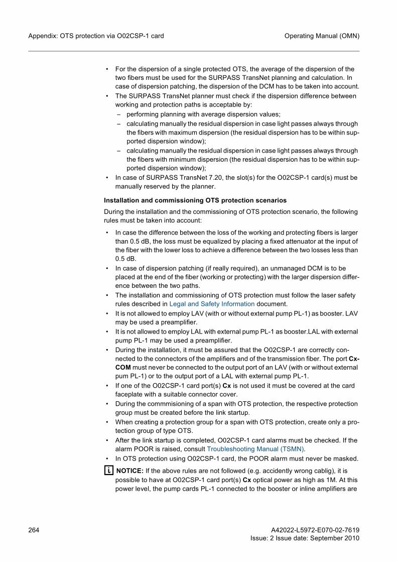
264 A42022-L5972-E070-02-7619Issue: 2 Issue date: September 2010
Operating Manual (OMN)Appendix: OTS protection via O02CSP-1 card
• For the dispersion of a single protected OTS, the average of the dispersion of the two fibers must be used for the SURPASS TransNet planning and calculation. In case of dispersion patching, the dispersion of the DCM has to be taken into account.
• The SURPASS TransNet planner must check if the dispersion difference between working and protection paths is acceptable by:– performing planning with average dispersion values;– calculating manually the residual dispersion in case light passes always through
the fibers with maximum dispersion (the residual dispersion has to be within sup-ported dispersion window);
– calculating manually the residual dispersion in case light passes always through the fibers with minimum dispersion (the residual dispersion has to be within sup-ported dispersion window);
• In case of SURPASS TransNet 7.20, the slot(s) for the O02CSP-1 card(s) must be manually reserved by the planner.
Installation and commissioning OTS protection scenariosDuring the installation and the commissioning of OTS protection scenario, the following rules must be taken into account:
• In case the difference between the loss of the working and protecting fibers is larger than 0.5 dB, the loss must be equalized by placing a fixed attenuator at the input of the fiber with the lower loss to achieve a difference between the two losses less than 0.5 dB.
• In case of dispersion patching (if really required), an unmanaged DCM is to be placed at the end of the fiber (working or protecting) with the larger dispersion differ-ence between the two paths.
• The installation and commissioning of OTS protection must follow the laser safety rules described in Legal and Safety Information document.
• It is not allowed to employ LAV (with or without external pump PL-1) as booster. LAV may be used a preamplifier.
• It is not allowed to employ LAL with external pump PL-1 as booster.LAL with external pump PL-1 may be used a preamplifier.
• During the installation, it must be assured that the O02CSP-1 are correctly con-nected to the connectors of the amplifiers and of the transmission fiber. The port Cx-COM must never be connected to the output port of an LAV (with or without external pum PL-1) or to the output port of a LAL with external pump PL-1.
• If one of the O02CSP-1 card port(s) Cx is not used it must be covered at the card faceplate with a suitable connector cover.
• During the commmisioning of a span with OTS protection, the respective protection group must be created before the link startup.
• When creating a protection group for a span with OTS protection, create only a pro-tection group of type OTS.
• After the link startup is completed, O02CSP-1 card alarms must be checked. If the alarm POOR is raised, consult Troubleshooting Manual (TSMN).
• In OTS protection using O02CSP-1 card, the POOR alarm must never be masked.
g NOTICE: If the above rules are not followed (e.g. accidently wrong cablig), it is possible to have at O02CSP-1 card port(s) Cx optical power as high as 1M. At this power level, the pump cards PL-1 connected to the booster or inline amplifiers are

A42022-L5972-E070-02-7619Issue: 2 Issue date: September 2010
265
Operating Manual (OMN) Appendix: OTS protection via O02CSP-1 card
switch off for all directions in the affected NE. This behavior occurs to avoid power level exceeding 1M and may affect traffic.

266 A42022-L5972-E070-02-7619Issue: 2 Issue date: September 2010
Operating Manual (OMN)Glossary
9 Glossary@CT @CT is a web-based craft terminal (i.e., element manager) software which provides web
access to SURPASS hiT 7300 NEs in the customer network without the use of a man-agement system. It communicates via SNMP with the NEs and uses the FTPS for upload/download of software or other data configuration (e.g., log files).
10 Gbit/s SmallForm-Factor Plugga-
ble
An XFP module is a swappable component mounted at the front panel of some types of hiT 7300 transponder cards. It acts as a boundary interface between the client signal and the DWDM line signal by performing the bidirectional optical/electrical traffic conver-sion.
Add/Drop channel An add/drop channel is an active channel added or dropped at any ONN-S NE at the considered pre-emphasis section.
Air filter An air filter is a one-piece replaceable element mounted in the shelf to protect the shelf from ingesting environmental dust or other airborne contaminants.
Alarm An alarm is a management mechanism intended to inform the user that there is a standing fault condition in the system.
Alarm log An alarm log provides a list of the alarms associated with a managed object, and provides the following information about each of the alarms: • the identification of the affected object • the identification of the failed NE or the NE in which the failed unit resides • the alarm severity • the time the event occurred • the indication whether the alarmed event is service affecting or not • the location and the affected traffic
Alarm severity Each failure is assigned a severity. The following values are used: • critical • major • minor • warning
Element Manager (EM) can configure the severity which is assigned to each fault cause by an alarm severity assignment profile. In addition, EM can specify that a fault cause shall not be alarmed. These fault causes will be blocked, hence do not lead to any LED alarm indications, log entries or alarm reporting.
Amplified Spontane-ous Emission
ASE is produced when a laser gain medium is pumped to produce a population inver-sion. Feedback of the ASE by the laser's optical cavity may produce laser operation if the lasing threshold is reached. Excess ASE is an unwanted effect in lasers, since it limits the maximum gain that can be achieved in the gain medium. ASE creates serious problems in any laser with high gain and/or large size.
Amplifier card The line amplifier cards provide the optical signal amplification via a gain block with one or two pump lasers, interstage access for dispersion compensation, a stage for connec-tion of external pumps, and gain control mechanisms.
Attenuator card A VOA card is a variable attenuator that can supply up to 8 EVOA channels. The VOA card is applicable in pre-emphasis.

A42022-L5972-E070-02-7619Issue: 2 Issue date: September 2010
267
Operating Manual (OMN) Glossary
Automatic LaserShutdown
ALS acts by disabling the laser of the forward transmission side if the receiving line is inactive (i.e., no signal is detected). During service provisioning, the ALS checks for link restoration in small time intervals and resumes the transmission (i.e., enables the trans-mission laser) when the line is restored.
Booster A Booster is an optical amplifier placed at the link section head end.
Booster-less card A booster-less line interface card is a unidirectional line interface card for the transmit direction of a DWDM line interface without amplification functionality. The booster-less line interface card can replace a booster amplifier card for short span applications.
C/DWDM filter pack C/DWDM filter pack is a passive filtering solution realized in a small filter pack shelf (SPF-1) which allows up to 4 filter modules to be plugged-in.
The C/DWDM filter pack does not require power supply. It is completely independent from the SURPASS hiT 7300 system from a management point of view.
Card A card is a plug-in unit that occupies one (or multiple) shelf slots. Cards perform specific electrical and/or optical functions within an NE.
Each card has a faceplate with information LEDs and, in most cases, several ports for interconnection of optical fibers and/or optical interfaces (e.g., SFP).
Card faceplate All cards are equipped with individual faceplates in order to meet EMI/ESD require-ments, and ensure heat dissipation. The card faceplate contains LEDs, and in some cases optical or electrical interfaces.
Card LEDs Card LEDs are luminous signals that can alert the user to: • The state of the power supply. • A card problem that requires card replacement. • The existence of communication or equipment alarms. • The presence or absence of traffic in the card.
Card slot A card slot is the insertion facility for a card in a shelf. Each card slot is designed for one or several particular card types.
Mechanical coding elements make sure that each card can be fully inserted only into a card slot that is suitable for the given card type. Therefore, fundamental shelf equipping errors (which might cause hardware damage or fatal malfunctions) are impossible.
Chain network A chain network is a network topology characterized by a chain connection between several NEs, i.e., the optical signal is transmitted from one end-point NE to another but new channels can be added, dropped or re-routed (to another optical path) along the optical path.
Channel powermonitor card
Channel power monitor cards provide in-service monitoring of optical channel power levels via an on-board Optical Spectrum Analyzer. The card has four input ports to monitor the channel spectrum from four separate points in an NE.
Chromatic disper-sion
Chromatic dispersion has the effect of spreading the signal pulse width, no longer allowing an accurate recognition of a single “one” bit or a single “zero” bit.
Client interface A client interface is a transponder interface that faces the client side of the link. Contrast with “line interface” which faces the transmission (line) side of the link.

268 A42022-L5972-E070-02-7619Issue: 2 Issue date: September 2010
Operating Manual (OMN)Glossary
Coarse WavelengthDivision Multiplex-
ing
CWDM solution allows a simple and low-cost implementation of a passive optical multi-plexing system (with compact passive multiplexer modules), which can be used for data collection and aggregation of multiple client data from different remote locations within enterprise, or small metropolitan networks.
Commissioning Commissioning an NE is the process of taking an installed NE and bringing it in to an operational state. The NE commissioning phase is performed after the NE is installed and powered-up.
Controller card NE controller cards (CCEP-2 and CCMP-2) provide the central monitoring and control-ling functions of the system, as well as the MCF to operate the Q and QF Ethernet inter-faces.
The controller card performs the following main functions: Fault Management, Perfor-mance Management, Configuration Management, Security Management, Equipment Management, Communication Management, Software Management (performing all software downloads, uploads, and software integrity functions) and controlling the NE alarm LEDs.
CWDM patch-cord A CWDM patch-cord solution is provided by the add/drop patch-cord. The patch-cord is an optical Y-cable with 3 LC/PC connectors, which allows the add/drop of a single CWDM channel.
Data Communica-tion Network
A DCN domain interconnects several NEs for the purpose of network management. The communication is established via the OSC of the optical links and an Ethernet/L2 switch-ing network implemented by the NEs.
Dense WavelengthDivision Multiplex-
ing
DWDM is a technology which simultaneously places a large number of optical signals (in the 1550 nm band) on a single optical fiber.
Differential PhaseShift Keying
A digital modulation technique used in the transmission of optical signals. DPSK is used in the optical line interface of the I01T40G-1, I01R40G-1 and I04T40G-1 cards, as well as the OPMDC-2 card.
DPSK transmits data by modulating the phase of a signal. The phase is changed if the current data bit is different from its predecessor. At a receiving end, phase changes are detected by comparing the phase of each signal element with the phase of a preceding signal element. ?
Dispersion Compen-sation Module card
DCM cards counteract the chromatic dispersion of the signal traveling through the optical fiber.
Element Manager SURPASS hiT 7300 EM enables the user to perform operation, administration and maintenance tasks with the SURPASS hiT 7300 system in a GUI environment.
Engineering OrderWire
The EOW interface is located at the NE controller cards and is used to establish confer-ence and selective calls from one NE to another NE(s) using a handset.
Erbium Doped FiberAmplifier
An EDFA is an optical fiber doped with a rare earth element (Erbium), which can amplify laser light in the 1550 nm region when pumped by an external laser source.
Error correction Error correction in a DWDM system is achieved with FEC and S-FEC functions. These functions ensure the detection and correction of data errors carried by a channel or channels.
A42022-L5972-E070-02-7619Issue: 2 Issue date: September 2010
269
Operating Manual (OMN) Glossary
Ethernet Ethernet is a family of frame-based computer networking technologies for LANs. It defines a number of wiring and signaling standards for the physical layer, through means of network access at the MAC/Data Link Layer, and a common addressing format.
Express channels An express channel is an active channel that travels over an entire pre-emphasis section, from ONN to ONN (except ONN-S) without being added (or dropped) at any ONN-S multiplexer (or demultiplexer).
External pump card An external pump card can be connected to an amplifier card to increase its normal output power, which is sometimes needed for longer spans, different fiber types.
Fan unit Each shelf is equipped with one or more fan units that provide cooling airflow for the cards.
Fault management Fault management reports all hardware and software malfunctions within an NE, and monitors the integrity of all incoming and outgoing digital signals.
File TransferProtocol
FTP is a network protocol used to transfer files from one computer to an NE and vice-versa through the network.
Filter card Filter cards act as multiplexers/demultiplexers by providing the primary wave division or aggregation of all the transponder signals and allowing access to a particular set of wavelengths from an optical fiber while passing the remaining wavelengths.
Forward Error Cor-rection
FEC is a technique that optimizes signal performance by providing a better OSNR tol-erance at the transponders, i.e., FEC enables the system to withstand more signal noise.
FEC is a coding algorithm that enables bit error detection and correction. FEC is a "for-ward" scheme, i.e., the receiver receives only the information needed to detect and correct bit errors and never requests a re-transmission.
Frequency Frequency is a physical attribute of a wave (e.g., an optical wave), defined as the number of wave cycles per time unit. The frequency is directly related to the wavelength.
Gain control Gain control of SURPASS hiT 7300 is provided by the EDFA modules in the line ampli-fier cards. Gain control ensures a sufficiently fast response to transients and keeps constant the gain between input and output of the EDFA line amplifier card.
Interstage Loss Most hiT 7300 amplifier cards feature two ports to connect an “interstage” device (typi-cally a DCM). Interstage loss is the power loss experienced by the optical signal passing through the interstage device.
Laser A laser is a device that generates an intense narrow beam of light by stimulating the emission of photons from excited atoms or molecules.
Laser safety Laser safety rules are a group of mechanisms and actions necessary to protect all users from harmful laser light emissions.
Laser Safety Bus SURPASS hiT 7300 LSB rings provide a reliable communication between cards to ensure a safe NE operation via APSD and APRM functions.
Line interface A line interface is a transponder interface that faces the line side of the link. Contrast with “client interface” which faces the client equipment side of the link.
Link section See Optical Multiplex Section

270 A42022-L5972-E070-02-7619Issue: 2 Issue date: September 2010
Operating Manual (OMN)Glossary
Long Haul SURPASS hiT 7300 LH segment is a DWDM application characterized by a reach of more than 500 km and up to 1200 km.
Mesh network A mesh network is a network topology which is characterized by the constant routing of the optical channel between the NEs. It allows a continuous connection and a reconfig-uration around a broken or blocked optical path by "hopping" from NE to NE until the destination is reached. A mesh network whose NEs are all connected to each other is a fully connected network.
Metro SURPASS hiT 7300 Metro segment is a DWDM application characterized by short path lengths of up to 200 km.
MPB communica-tions
The RMH07 and 1RU-R Long Reach Transport Series from MPB Communications consists of amplifiers designed to transmit and receive signals over fiber optic links from 100 to more than 400 km in a single span using SON NEs.
Network CraftTerminal
NCT is a network management craft terminal (i.e., element manager) software which is used for either local or remote network management.
Network Element An NE is a self-contained logical unit within the network. The NE can be uniquely addressed and individually managed via software.
Each NE consists of hardware and software components to perform given electrical and optical functions within the network.
Network ElementConfiguration File
NCFs contain most of the necessary configurations for each NE of the planned network. However, several configurations (e.g., DCN and NE configurations) must be performed manually with the support of the NE commissioning manuals.
Network Manage-ment
The network management layer includes all the required functions to manage the optical network in an effective and user-friendly way, such as the visualization of the network topology, creation of services, and correlation of alarms to network resources.
Network topologies A topology of a network is defined by the list of NEs included in the network and the list of links that connect those NEs (e.g., point-to-point, chain, ring, etc.)
Nodal degree The nodal degree of an NE is the number of NEs that are directly connected to the NE.
Non-return to Zero A data encoding technique used to transmit digital data over the line interface of the fol-lowing cards: I04T2G5-1; I01T10G-1; I08T10G-1; I05AD10G-1; I04TQ10G-1 and I22CE10G-1. In telecommunication, a non-return-to-zero (NRZ) line code is a binary code in which 1's are represented by one significant condition (usually a positive voltage) and 0's are represented by some other significant condition (usually a negative voltage), with no other neutral or rest condition.?
OADM architectures OADM architectures refer to the capability of an OADM NE to perform some optical tasks within the SURPASS hiT 7300 network. In SURPASS hiT 7300 the following OADM architectures are available: • Small • Terminal • Flexible • FullAccess • Reconfigurable • PXC

A42022-L5972-E070-02-7619Issue: 2 Issue date: September 2010
271
Operating Manual (OMN) Glossary
Optical Add-DropMultiplexer
An OADM is an optical node NE used for multiplexing and routing different optical channels of into or out of an optical fiber. An OADM NE is generally used for the con-struction of a ring-based network. "Add" and "drop" refer to the capability of the NE to add one or more channels to an existing DWDM signal, and/or to drop one or more channels and/or routing those signals to another optical path.
Optical Channel A predefined wavelength that can be used to transmit a bit stream by means of a mod-ulated light signal.
Optical channelcontrol
Optical channel control manages the optical channel state information through the entire optical path. The optical channel control activates mechanisms to recover the normal operation of the optical path in a link failure scenario, or activate mechanisms to manage operations in case of an optical channel upgrade/ downgrade scenario. The activation of such mechanisms, depends on the optical channel state information monitored on each NE. The transmission of this information along the optical path, between NEs, is provided by the OSC.
Optical channel pro-tection card
An optical channel protection card is a passive card which contains 6 optical splitters. Three of those splitters act as combiners to switch the traffic together with the transpon-der cards. The remaining three are used for bridging the traffic for protection.
Up to three protection groups can be created and managed by the optical channel pro-tection card (i.e., three pairs of client interfaces).
Optical LineRepeater
An OLR is an NE which is used for optical signal amplification and dispersion compen-sation.
Optical link control Optical link control optimizes and maintains the operation of individual link sections and pre-emphasis sections. Most of the optical link control functions are executed by the CCEP card, and the time-critical functions are executed by the line amplifier cards.
Optical MultiplexSection
An optical multiplex section (or link section) is the optical segment from the booster of an ONN to the pre-amplifier of the next adjacent ONN.
Optical NetworkNode
An ONN is an NE where the incoming channels are either dropped or routed to a line in a different direction, outgoing channels can also be added locally. Apart from multiplex-ing and demultiplexing an ONN NE implements optical or 3R signal regeneration and dispersion compensation.
Optical path The path followed by an optical channel from the first multiplexer to the last demulti-plexer.
Optical Signal toNoise Ratio
OSNR is the ratio of an optical signal power to the noise power in the signal.
Optical SpectrumAnalyzer
An OSA is a device that measures properties of an optical signal within a defined spec-trum.
Optical SupervisoryChannel
An OSC is a supervisory channel that is transmitted/received by the line amplifier cards. It provides all the network management communication required to set-up and maintain a DWDM system configuration, fault management, performance monitoring, and software maintenance.
Optical Transmis-sion Section
An optical transmission section (or span) is any fiber segment between two adjacent amplifiers (i.e., between two NEs).

272 A42022-L5972-E070-02-7619Issue: 2 Issue date: September 2010
Operating Manual (OMN)Glossary
Performance man-agement
Performance monitoring and signal quality analysis provide information for detecting and alerting, a cause that could lead to a degraded performance before a failure is declared.
Point-to-pointnetwork
A point-to-point network is a network topology characterized by a connection between two end-point NEs, i.e., the optical signal is transmitted from one end-point to another end-point without add or drop of channels. Applications where the span length is con-siderably big may require an amplification/regeneration (done by OLR NEs) along the optical path.
Power DistributionPanel
A PDP is the device responsible for the power distribution of all the racks of an NE. It contains fuses (or circuit breakers) to protect all the dual-redundant power feeds con-nected to each shelf in the rack.
Power meter An optical power meter is the equipment recommended to use in case of single optical channel power measurement.
Power tilt Spectrum power tilt occurs when a flat DWDM signals travel through transmission fiber. Due to stimulated Raman scattering, shorter wavelength channels will pump longer wavelength channels, and so transfer their energy to longer wavelength channels.
Preamplifier Preamplifier is an optical amplifier placed at the link section tail end.
Pre-emphasis The Pre-emphasis method is applied to pre-emphasis sections, and is used to optimize the optical link by means of optical power adjustment (manual or automatic).
Pre-emphasismethod
The pre-emphasis method is applied to pre-emphasis sections and is used to optimize the optical link by means of optical power adjustment.
Pre-emphasissection
A pre-emphasis section is the optical segment from the booster of an ONN (except ONN-S) to the pre-amplifier of the next adjacent ONN (except ONN-S).
Pump laser A pump laser is a laser with a wavelength different from the signal laser, used as the energy source for signal amplification.
Rack A rack is the main unit of the SURPASS hiT 7300, it carries all system devices in a specific arrangement. The most important elements placed in the rack are the shelves and the Power Distribution Panel.
Raman amplification The basis of Raman amplification is the energy scattering effect called SRS. The SRS is a non-linear effect inherent to the fiber itself. SRS involves a transfer of power from a signal at a higher frequency (lower wavelength) to one at a lower frequency (higher wavelength), due to inelastic collisions in the fiber medium. It can be used for optical amplification, in which the higher frequency laser serves as a pump source, amplifying the lower frequency wave carrying the actual traffic signal to be amplified.
Raman pump card Raman pump cards must be inserted at the receiving line interface. They are normally used in long span applications to ensure that the same amplifier spacing can be achieved with lower EDFA output power per channel, allowing a higher total number of channels.
For certain links where the non-linear effects limit an increase in the number of spans, a channel power reduction decreases the non-linear effects, and therefore allows a higher number of spans. Raman amplifiers are preferably applied to bridge single extra long spans.

A42022-L5972-E070-02-7619Issue: 2 Issue date: September 2010
273
Operating Manual (OMN) Glossary
Regenerator A regenerator is a device used to extend the reach of fiber-optic traffic communications, by compensating the attenuation and the distortion of the optical signal.
The regenerator converts the received optical signal to an electrical signal, processes it, reconverts it to an optical signal and retransmits it.
Regional SURPASS hiT 7300 Regional segment is a DWDM application characterized by path lengths starting at 200 km and for high traffic volumes. These networks are often used as regional collector networks to feed into LH portions of the network. Regional DWDM networks have typical path lengths of up to 500 km.
Remote OpticallyPumped Amplifier
A ROPA module is a passive unit with a Erbium doped fiber to amplify the optical signal. It is placed in the transmission cable to extend the long single span length.
Ring network A ring network is a network topology in which each NE connects to exactly two other NEs, forming a circular optical path for signals (i.e., a ring).
Security manage-ment
Security Management controls the individual access to particular NE functions via the network management system and/or via a craft terminal, using a hierarchical security management user ID, and password concept.
Service Provisioning Service provisioning consists of establishing and managing OCh connections via GMPLS signaling.
Shelf The rack-mountable housing into which cards are installed. The shelf contains terminals for connection of the power supply voltage that is distributed to each card. Major com-ponents of each shelf are card slots, backplane, Connector Panel, Fan Unit(s) and Air Filter.
Simple NetworkManagement
Protocol
SNMP is used in network management systems to monitor network-attached devices for conditions that warrant administrative control. It consists of a set of standards for network management, including an application layer protocol, a database schema, and a set of data objects.
Small Form-FactorPluggable
An SFP module is a swappable component mounted at the front panel of some types of hiT 7300 transponder cards. It acts as a boundary interface between the client signal and the DWDM line signal by performing bidirectional optical/electrical traffic conver-sion.
Software manage-ment
Software management performs all software downloads, uploads, and software integrity functions.
Span See Optical Transmission Section
Span loss Span loss is the optical power loss measured in dBs between two adjacent NEs.
Standalone OpticalNode
A SON is a DWDM NE that can be used in passive DWDM (e.g., point-to-point and remote transponder solutions) and long single span applications.
Standalone OpticalNode Flatpack
A SONF is a DWDM NE realized in a flatpack shelf which can be used in passive DWDM (e.g., point-to-point and remote transponder solutions).
Stimulated BrillouinScattering
SBS is the interaction of photons and optical phonons (acoustic phonons). The latter are the particles, which can be assigned to vibrations of the array of atoms and electrons. The SBS acts in backward direction and it is especially important when there is bidirec-tional transmission. In this case, a channel interferes with itself causing significant dis-tortion and loss in forward direction.

274 A42022-L5972-E070-02-7619Issue: 2 Issue date: September 2010
Operating Manual (OMN)Glossary
Tandem ConnectionMonitoring
TCMs are configurable parameters (via EM) of the transponders. They provide a PM of the all OTN (i.e., end-to-end connection) or specific sections only and implement an ODU termination provisioned to support up to six TCM levels.
TelecommunicationNetwork Manage-
ment SystemCore/Cross Domain
Manager
TNMS Core/CDM is an integrated solution designed for large, medium and small size networks. It supports NEs with DWDM, OTH, SDH, PDH, Ethernet in line, star, ring and mesh network configurations. TNMS Core/CDM can be used to manage networks in the access, edge, metro, core and backbone levels.
TelecommunicationNetwork Manage-
ment System CraftTerminal
TNMS CT is a transparent software platform for SDH and DWDM NEs using QD2, QST, QST V2, Q3 or SNMP telegram protocols. It supports line, star, ring and mesh networks and provides access to NEs via Ethernet interface or via a serial line interface (RS232).
Telemetry Interface TIF sensors (inputs) and TIF actors (outputs) can be found in the NEs’ controller cards as a separate module called TIF module. The TIF module is intended to be used for tra-ditional user-defined “housekeeping” purposes (e.g., fire alarm, over-temperature alarm, door-open alarm, lights, air conditioning, etc.).
Trail Trace Identifier TTI is a transponder card parameter (configurable via EM) of which is used to verify correct cabling or correct TCM configuration. The basic principle is that specific overhead bytes are reserved for Trace Messages of the user's choosing. By specifying the Actually Sent (transmitted) and the Expected (received) trace messages, the system can automatically verify that fiber connections have been made as intended. This is accomplished by comparing the expected Trace Message to that actually received. If they differ, an alarm is raised, alerting personnel of the incorrect connections.
TransactionLanguage 1
TL1 is a telecommunications management protocol. It is a cross-vendor, cross-technol-ogy man-machine language, which is used to manage optical and broadband access infrastructures in North America. It is defined in GR-831 by Telcordia Technologies.
TransNet Planning of a SURPASS hiT 7300 network is done by the SURPASS TransNet tool. SURPASS TransNet is a sophisticated software simulation tool developed specifically for designing and/or upgrading optical DWDM networks with SURPASS hiT 7300. It runs on PCs using Windows 2000 or Windows XP operating systems.
Transponder card A transponder card receives an optical input signal and converts it to an optical output signal suitable for DWDM multiplexing and transmission.
Transponderloopback
Loopbacks are diagnostic tests that can be activated via EM. Loopbacks return the transmitted signal back to the sending device after the signal has passed across a par-ticular link. The returned signal can then be compared to the transmitted one. Any dis-crepancy between the transmitted and the returned signal helps to trace faults.
UDCM tray A UDCM tray is a mechanical shelf mounted in a rack, which can hold up to 4 UDCMs.
Ultra Long Haul SURPASS hiT 7300 ULH segment is a DWDM application characterized by long path lengths of up to 1600 km.
Unidirectional Dis-persion Compensa-
tion Module
UDCMs provide a dispersion compensation of the DWDM signal. They are not supplied as shelf plug-in cards, being mounted in a specific plug-in box inside the UDCM tray.
UDCMs are available in "single-height" UDCM and "double-height" UDCM. A blank (dummy) UDCM is also available to be installed in those positions that do not have an actual UDCM installed.

A42022-L5972-E070-02-7619Issue: 2 Issue date: September 2010
275
Operating Manual (OMN) Glossary
User Channel SURPASS hiT 7300 user channels are used for bidirectional connections between NEs via the OSC or GCC0, providing the customer with a point-to-point Ethernet connection for specific data network or remote access to NEs not reachable via DCN.
VOA See Attenuator Card
Wavelength Wavelength is a physical attribute of a wave (e.g., an optical wave), defined as the distance between corresponding points of two consecutive wave cycles.
The wavelength is directly related to the frequency of the wave.
Wrist strap A grounded anti-static strap worn on the wrist to prevent electrostatic discharge that may damage electronic equipment.

276 A42022-L5972-E070-02-7619Issue: 2 Issue date: September 2010
Operating Manual (OMN)Abbreviations
10 AbbreviationsAC Alternating Current
@CT Web-based Craft Terminal
ADF Armored Fiber Distribution Frame
AIS Alarm Indication Signal
ALS Automatic Laser Shutdown
ANSI American National Standards Institute
APD Avalanche Photodiode
APR Address Resolution Protocol
APRM Automatic Power Reduction Mode
APS Application Program System
APSD Automatic Power Shutdown
ASE Amplified Spontaneous Emission
ASON Automatic Switched Optical Network
AWG Arrayed Waveguide Grating
BBE Background Block Errors
BDI Backward Defect Indication
BER Bit Error Rate
BOL Begin-of-Life
CAPEX Capital Expenditure
CARP Common Address Redundancy Protocol
CCAMP Common Control And Measurement Plane
CD Compact Disk
CE Communauté Européenne
CLI Command Line Interface
CML Command and Message List
CMS Control plane MIB Stub
COPA Connector Panel
COS Class of Service
CT Craft Terminal
CV Code Violations

A42022-L5972-E070-02-7619Issue: 2 Issue date: September 2010
277
Operating Manual (OMN) Abbreviations
CWDM Coarse Wavelength Division Multiplexing
DC Coding Violations
DCF Dispersion Compensation Fiber
DCM Dispersion Compensation Module
DCN Data Communication Network
DGD Differential Group Delay
DHCP Dynamic Host Configuration Protocol
DLI Delay Line Interferometer
DNS Domain Name Service
DOP Degree Of Polarization
DPSK Differential Phase-shift Keying
DSF Dispersion Shifted Fiber
DSLAM Digital Subscriber Line Access Multiplexer
DTMF Dual Tone Multi-Frequency
DWDM Dense Wavelength Division Multiplexing
EAM Electro-Absorption Modulator
EBP Earth Bonding Point
EDF Erbium Doped Fiber
EDFA Erbium Doped Fiber Amplifier
EGB Elektrostatisch gefährdetes Bauteil
EM Element Manager
EMI Electromagnetic Interference
EN European Norm
EOCI External Open Connection Indication
EOL End-of-Life
EOW Engineering Order Wire
EPC Enhanced Power Control
EPL Ethernet Private Line
ERO Explicit Route Object
ES Errored Seconds
ESD Electrostatically Sensitive Device
ETS European Telecommunications Standard

278 A42022-L5972-E070-02-7619Issue: 2 Issue date: September 2010
Operating Manual (OMN)Abbreviations
ETSI European Telecommunications Standards Institute
EVPL Ethernet Virtual Private Line
FBG Fiber Bragg Grating
FC Fiber Channel
FCC Federal Communications Commission
FDI Forward Defect Indication
FEC Forward Error Correction
FIT Failures In Time
FPGA Field Programmable Gate Array
FTP File Transfer Protocol
FTPS File Transfer Protocol Secure
G-AIS Generic Alarm Indication Signal
GbE Gigabit Ethernet
GCC Generic Communication Channel
GFP-T Generic Framing Protocol - Transparent
GMPLS Generalized Multi-Protocol Label Switching (GMPLS)
GMT Greenwich Mean Time
GUI Graphical User Interface
HTTP Hyper Text Transfer Protocol
HU Height Unit (1 HU = 1.75 inches)
HW Hardware
I2C Inter-Integrated Circuit
ICMA Interconnect, Configuration and Mechanical Assembly manual
ICMP Internet Control Message Protocol
ID Identifier
IEC International Electrotechnical Commission
ILAN Inter-shelf Local Area Network
INNI Internal Network to Network Interface
IP Internet Protocol
ISL Interstage Loss
ITMN Installation and Test Manual
ITTI Internal Trail Trace Identifier

A42022-L5972-E070-02-7619Issue: 2 Issue date: September 2010
279
Operating Manual (OMN) Abbreviations
JRE Java Runtime Environment
LAN Local Area Network
LAx Line Amplifier
LEAF Large Effective Area Fiber
LED Light Emitting Diode
LH Long Haul
LLDP Link Layer Discovery Protocol
LOM List of Material
LOS Loss of Signal
LSB Laser Safety Bus
LSP Label Switched Path
LSR Label Switch Route
LWL Lichtwellenleiter
MAC Media Access Control
MCF Message Communication Function
MDF Medium Dispersion Fiber
MEMS-WSS Micro-Electro-Mechanical System - Wavelength Selective Switch
MIB Management Information Base
MLSE Maximum Likelihood Sequence Estimator
MPBC MPB communications
MPE Maximum Permissible Exposure
MPLS Multiprotocol Label Switching
MSA Multi-Source Agreement
MST Multiple Spanning Tree
MSTP Multiple Spanning Tree Protocol
MS-AIS Multiplex Section Alarm Indication Signal
MTU Maximum Transmission Unit
MZM Mach-Zehnder Modulator
NAPT Network Address Port Translation
NCF Network Element Configuration File
NCT Network Craft Terminal
NE Network Element

280 A42022-L5972-E070-02-7619Issue: 2 Issue date: September 2010
Operating Manual (OMN)Abbreviations
NMS Network Management System
NNI Network to Network Interface
NTP Network Time Protocol
NZ-DSF Nonzero-dispersion-shifted Fiber
OADM Optical Add-Drop Multiplexer
OChP Optical Channel Protection
ODF Optical Distribution Frame
ODU Optical channel Data Unit
OEM Original Equipment Manufacturer
OLC Optical Link Commissioning
OLR Optical Line Repeater
OMN Operating Manual
OMS Optical Multiplex Section
ONN Optical Network Node
ONN-I Optical Network Node - Interconnect
ONN-I80 Optical Network Node - Interconnect 80 Channels
ONN-R Optical Network Node - Reconfigurable
ONN-R2 Optical Network Node - Reconfigurable 2
ONN-RT Optical Network Node - Reconfigurable/Tunable
ONN-R80 Optical Network Node - Reconfigurable 80 Channels
ONN-RT80 Optical Network Node - Reconfigurable/Tunable 80 Channels
ONN-S Optical Network Node - Small
ONN-T Optical Network Node - Terminal
ONN-T80 Optical Network Node - Terminal 80 Channels
ONN-X Optical Network Node - Cross-Connect
ONN-X80 Optical Network Node - Cross-Connect 80 Channels
OPEX Operational Expenditure
OPU Optical channel Payload Unit
OS Operating System
OSA Optical Spectrum Analyzer
OSC Optical Supervisory Channel
OSNR Optical Signal to Noise Ratio

A42022-L5972-E070-02-7619Issue: 2 Issue date: September 2010
281
Operating Manual (OMN) Abbreviations
OSU Optical Supervisory Unit
OTDR Optical Time Domain Reflectometer
OTH Optical Transport Hierarchy
OTN Optical Transport Network
OTS Optical Transmission Section
OTU Optical Transport Unit
PC Personal Computer
PD Product Description
PDP Power Distribution Panel
PDU Packet Data Unit
PHF Power High Failure
PIU Plug In Unit
PLC-WSS Planar Lightwave Circuit-Wavelength Selective Switch
PLF Power Line Filter
PM Performance Management
PMD Polarization Mode Dispersion
PMP Performance Monitoring Points
PRBS Pseudo Random Bit Sequence
PSCF Pure Silica Core Fiber
PSU Power Supply Unit
PXC Photonic Cross-Connect
QoS Quality of Service
RAM Random Access Memory
ROADM Reconfigurable OADM
ROPA Remote Optically Pumped Amplifier
RSVP Resource Reservation Setup Protocol
S-FEC Super Forward Error Correction
SAPI Source Access Point Identifier
SBS Stimulated Brillouin Scattering
SDH Synchronous Digital Hierarchy
SEFS Severely Errored Framing Seconds
SELV Safety Extra Low Voltage

282 A42022-L5972-E070-02-7619Issue: 2 Issue date: September 2010
Operating Manual (OMN)Abbreviations
SES Severely Errored Seconds
SFP Small Form-Factor Pluggable
SLC Stratalight Communications
SNC/I Sub-Network Connection protection with Inherent monitoring
SNCP Sub-Network Connection Protection
SNMP Simple Network Management Protocol
SON Standalone Optical Node
SONET Synchronous Optical NETwork
SONF Standalone Optical Node Flatpack
SPC Standard Power Control
SPM Self Phase Modulation
SRS Stimulated Raman Scattering
SSM Solution Sales Management
SSMF Standard Single Mode Fiber
STP Spanning Tree Protocol
SU System Unit (1 SU = 25 mm)
SW Software
TCA Threshold Crossing Alert
TCM Tandem Connection Monitoring
TCP Transmission Control Protocol
TDC Tunable Dispersion Compensation
TDM Time Division Multiplexing
TID Target Identifier
TIF Telemetry Interface
TIM Trace Identifier Mismatch
TL1 Transaction Language 1
TMN Telecommunication Management Network
TNMS Core/CDM Telecommunication Network Management System Core/Cross Domain Manager
TNMS CT Telecommunication Network Management System Craft Terminal
TP Termination Point
TPID Tag Protocol Identifier
TSMN Troubleshooting Manual

A42022-L5972-E070-02-7619Issue: 2 Issue date: September 2010
283
Operating Manual (OMN) Abbreviations
TTI Trail Trace Identifier
TTL Time to Live
TW-C TrueWave Classic
UAS Unavailable Seconds
UDCM Unidirectional Dispersion Compensation Module
UDP Universal Datagram Protocol
UL Underwriters Laboratories
ULH Ultra Long Haul
UMN User Manual
UNI User-to-Network Interface
UNI-P User-to-Network Interface - Port based
UNI-S User-to-Network Interface - Service based
USM User-based Security Model
UTC Universal Time Coordinated
VACM View-based Access Control Model
VLAN Virtual Local Area Network
VOA Variable Optical Attenuator
WAN Wide Area Network
WDM Wavelength Division Multiplexing
WEEE Waste Electrical and Electronic Equipment
WSS Wavelength Selective Switch
XFP 10 Gbit/s Small Form-Factor Pluggable
XPM Cross Phase Modulation