configuration and data management - infohouseinfohouse.p2ric.org/ref/16/15350.pdf2.3.7 software...
TRANSCRIPT

LIFE
CYCLE
ASSET
M ANAGEMENT
Good Practice GuideGPG-FM-012
Configuration and Data Management
April 1996
Department of EnergyOffice of Field Management
Office of Project and Fixed Asset Management

Contents GPG-FM-012
March 1996 iii
1. INTRODUCTION . . . . . . . . . . . . . . . . . . . . . . . . . . . . . . . . . . . . . . . . . . . . . . . . . . . . . . . 1
2. PRINCIPLES AND PROCESSES. . . . . . . . . . . . . . . . . . . . . . . . . . . . . . . . . . . . . . . . . . . 72.1 Process Overview. . . . . . . . . . . . . . . . . . . . . . . . . . . . . . . . . . . . . . . . . . . . . . . . . . . . 72.2 Roles . . . . . . . . . . . . . . . . . . . . . . . . . . . . . . . . . . . . . . . . . . . . . . . . . . . . . . . . . . . . . 112.3 Guidelines for Programs, Projects and Operating Facilities. . . . . . . . . . . . . . . . . . . . . 11
2.3.1 Plans and Procedures. . . . . . . . . . . . . . . . . . . . . . . . . . . . . . . . . . . . . . . . . . . 112.3.2 Technical Baseline Identification. . . . . . . . . . . . . . . . . . . . . . . . . . . . . . . . . . 142.3.3 Establishment of Baselines. . . . . . . . . . . . . . . . . . . . . . . . . . . . . . . . . . . . . . . 162.3.4 Change Control. . . . . . . . . . . . . . . . . . . . . . . . . . . . . . . . . . . . . . . . . . . . . . . 16
2.3.4.1 Executive Baseline Change Control Board (Level 0). . . . . . . . . . . 172.3.4.2 Program Baseline Change Control Board (Level 1). . . . . . . . . . . . 172.3.4.3 Field Element Change Control Boards (Level 2). . . . . . . . . . . . . . 172.3.4.4 Contractor Change Control Boards (Level 3). . . . . . . . . . . . . . . . 182.3.4.5 CCB Secretariat Organization. . . . . . . . . . . . . . . . . . . . . . . . . . . . 18
2.3.5 Configuration Identification. . . . . . . . . . . . . . . . . . . . . . . . . . . . . . . . . . . . . . 182.3.6 Traceability . . . . . . . . . . . . . . . . . . . . . . . . . . . . . . . . . . . . . . . . . . . . . . . . . . 202.3.7 Software Configuration Management. . . . . . . . . . . . . . . . . . . . . . . . . . . . . . 202.3.8 Interface Control. . . . . . . . . . . . . . . . . . . . . . . . . . . . . . . . . . . . . . . . . . . . . . 242.3.9 Data Management. . . . . . . . . . . . . . . . . . . . . . . . . . . . . . . . . . . . . . . . . . . . . 242.3.10 Reporting. . . . . . . . . . . . . . . . . . . . . . . . . . . . . . . . . . . . . . . . . . . . . . . . . . 252.3.11 Reviews . . . . . . . . . . . . . . . . . . . . . . . . . . . . . . . . . . . . . . . . . . . . . . . . . . . . 25
2.3.11.1 Programmatic Assessment. . . . . . . . . . . . . . . . . . . . . . . . . . . . . . . 262.3.11.2 Physical Configuration Assessments. . . . . . . . . . . . . . . . . . . . . . . 26
2.3.12 Control of Deviations and Waivers. . . . . . . . . . . . . . . . . . . . . . . . . . . . . . . . 262.3.13 Waste Inventory Configuration. . . . . . . . . . . . . . . . . . . . . . . . . . . . . . . . . . . 27
2.4 Additional Guidelines for Projects. . . . . . . . . . . . . . . . . . . . . . . . . . . . . . . . . . . . . . . 282.4.1 Establishment of the Technical Baseline for Projects. . . . . . . . . . . . . . . . . . . 282.4.2 Change Control for Projects. . . . . . . . . . . . . . . . . . . . . . . . . . . . . . . . . . . . . 28
2.4.2.1 Change Initiation and Submittal. . . . . . . . . . . . . . . . . . . . . . . . . . . 292.4.2.2 Change Review and Impact Evaluation. . . . . . . . . . . . . . . . . . . . . 292.4.2.3 Change Disposition. . . . . . . . . . . . . . . . . . . . . . . . . . . . . . . . . . . . 302.4.2.4 Directed Changes. . . . . . . . . . . . . . . . . . . . . . . . . . . . . . . . . . . . . 312.4.2.5 Change Implementation. . . . . . . . . . . . . . . . . . . . . . . . . . . . . . . . . 312.4.2.6 Training . . . . . . . . . . . . . . . . . . . . . . . . . . . . . . . . . . . . . . . . . . . . 312.4.2.7 Change Closeout. . . . . . . . . . . . . . . . . . . . . . . . . . . . . . . . . . . . . . 352.4.2.8 Change Tracking. . . . . . . . . . . . . . . . . . . . . . . . . . . . . . . . . . . . . . 35
2.5 Additional Guidelines for Operating Facilities. . . . . . . . . . . . . . . . . . . . . . . . . . . . . . . 352.5.1 Establishment of the Technical Baseline for Facilities. . . . . . . . . . . . . . . . . . . 362.5.2 Operating Facility Change Control Boards. . . . . . . . . . . . . . . . . . . . . . . . . . . 38

Contents GPG-FM-012
March 1996 iv
2.5.3 Work Control. . . . . . . . . . . . . . . . . . . . . . . . . . . . . . . . . . . . . . . . . . . . . . . . 392.5.4 Change Control for Operating Facilities. . . . . . . . . . . . . . . . . . . . . . . . . . . . . 39
2.5.4.1 Change Initiation and Submittal. . . . . . . . . . . . . . . . . . . . . . . . . . . 392.5.4.2 Change Review and Impact Evaluation. . . . . . . . . . . . . . . . . . . . . 412.5.4.3 Change Disposition. . . . . . . . . . . . . . . . . . . . . . . . . . . . . . . . . . . . 412.5.4.4 Directed Changes. . . . . . . . . . . . . . . . . . . . . . . . . . . . . . . . . . . . . 422.5.4.5 Change Implementation. . . . . . . . . . . . . . . . . . . . . . . . . . . . . . . . . 422.5.4.6 Training . . . . . . . . . . . . . . . . . . . . . . . . . . . . . . . . . . . . . . . . . . . . 462.5.4.7 Change Closeout. . . . . . . . . . . . . . . . . . . . . . . . . . . . . . . . . . . . . . 462.5.4.8 Change Tracking. . . . . . . . . . . . . . . . . . . . . . . . . . . . . . . . . . . . . . 46
2.5.5 Modification Control. . . . . . . . . . . . . . . . . . . . . . . . . . . . . . . . . . . . . . . . . . . 472.5.5.1 Requests for Facility Modifications. . . . . . . . . . . . . . . . . . . . . . . . 472.5.5.2 Design . . . . . . . . . . . . . . . . . . . . . . . . . . . . . . . . . . . . . . . . . . . . . 482.5.5.3 Installation . . . . . . . . . . . . . . . . . . . . . . . . . . . . . . . . . . . . . . . . . . 492.5.5.4 Documentation. . . . . . . . . . . . . . . . . . . . . . . . . . . . . . . . . . . . . . . 492.5.5.5 Training . . . . . . . . . . . . . . . . . . . . . . . . . . . . . . . . . . . . . . . . . . . . 502.5.5.6 Quality Verification. . . . . . . . . . . . . . . . . . . . . . . . . . . . . . . . . . . . 502.5.5.7 Materials Procurement. . . . . . . . . . . . . . . . . . . . . . . . . . . . . . . . . 512.5.5.8 Schedule. . . . . . . . . . . . . . . . . . . . . . . . . . . . . . . . . . . . . . . . . . . . 51
2.5.6 Temporary Modification Control. . . . . . . . . . . . . . . . . . . . . . . . . . . . . . . . . . 512.5.6.1 Technical Review. . . . . . . . . . . . . . . . . . . . . . . . . . . . . . . . . . . . . 522.5.6.2 Authorization. . . . . . . . . . . . . . . . . . . . . . . . . . . . . . . . . . . . . . . . 532.5.6.3 Installation . . . . . . . . . . . . . . . . . . . . . . . . . . . . . . . . . . . . . . . . . . 542.5.6.4 Documentation. . . . . . . . . . . . . . . . . . . . . . . . . . . . . . . . . . . . . . . 542.5.6.5 Reviews of Installed Temporary Modifications. . . . . . . . . . . . . . . 55
2.5.7 Setpoint Control. . . . . . . . . . . . . . . . . . . . . . . . . . . . . . . . . . . . . . . . . . . . . . 552.5.7.1 Facility Setpoint Document Control. . . . . . . . . . . . . . . . . . . . . . . 562.5.7.2 Program Procedures. . . . . . . . . . . . . . . . . . . . . . . . . . . . . . . . . . . 562.5.7.3 Technical Review of Proposed Changes. . . . . . . . . . . . . . . . . . . . 562.5.7.4 Implementation. . . . . . . . . . . . . . . . . . . . . . . . . . . . . . . . . . . . . . . 572.5.7.5 Closeout. . . . . . . . . . . . . . . . . . . . . . . . . . . . . . . . . . . . . . . . . . . . 57
2.6 Computer Software Change Control. . . . . . . . . . . . . . . . . . . . . . . . . . . . . . . . . . . . . 572.6.1 Software Change Control. . . . . . . . . . . . . . . . . . . . . . . . . . . . . . . . . . . . . . . 572.6.2 Software Change Packages. . . . . . . . . . . . . . . . . . . . . . . . . . . . . . . . . . . . . . 582.6.3 Periodic Verification. . . . . . . . . . . . . . . . . . . . . . . . . . . . . . . . . . . . . . . . . . . 582.6.4 Records. . . . . . . . . . . . . . . . . . . . . . . . . . . . . . . . . . . . . . . . . . . . . . . . . . . . . 59
2.7 Technical Reviews. . . . . . . . . . . . . . . . . . . . . . . . . . . . . . . . . . . . . . . . . . . . . . . . . . . 592.7.1 Applications Requiring Technical Reviews. . . . . . . . . . . . . . . . . . . . . . . . . . 592.7.2 Administrative Controls. . . . . . . . . . . . . . . . . . . . . . . . . . . . . . . . . . . . . . . . . 602.7.3 Technical Review Procedures. . . . . . . . . . . . . . . . . . . . . . . . . . . . . . . . . . . . 60

Contents GPG-FM-012
March 1996 v
2.8 Document Control for Configuration Management. . . . . . . . . . . . . . . . . . . . . . . . . . . 612.8.1 Document Control Administration. . . . . . . . . . . . . . . . . . . . . . . . . . . . . . . . . 622.8.2 Procedures. . . . . . . . . . . . . . . . . . . . . . . . . . . . . . . . . . . . . . . . . . . . . . . . . . 632.8.3 Drawing Control. . . . . . . . . . . . . . . . . . . . . . . . . . . . . . . . . . . . . . . . . . . . . . 632.8.4 Vendor Information. . . . . . . . . . . . . . . . . . . . . . . . . . . . . . . . . . . . . . . . . . . . 63
3. MEASURING FOR RESULTS . . . . . . . . . . . . . . . . . . . . . . . . . . . . . . . . . . . . . . . . . . . 65
4. SUGGESTED READING AND REFERENCES . . . . . . . . . . . . . . . . . . . . . . . . . . . . . . 674.1 DOE Rules, Orders, and Standards. . . . . . . . . . . . . . . . . . . . . . . . . . . . . . . . . . . . . . 674.2 DOE Project Management Guides. . . . . . . . . . . . . . . . . . . . . . . . . . . . . . . . . . . . . . . 684.3 Other References. . . . . . . . . . . . . . . . . . . . . . . . . . . . . . . . . . . . . . . . . . . . . . . . . . . . 68
5. DEFINITIONS . . . . . . . . . . . . . . . . . . . . . . . . . . . . . . . . . . . . . . . . . . . . . . . . . . . . . . . . . 71
6. ASSISTANCE. . . . . . . . . . . . . . . . . . . . . . . . . . . . . . . . . . . . . . . . . . . . . . . . . . . . . . . . . . 72
7. RELATED TRAINING . . . . . . . . . . . . . . . . . . . . . . . . . . . . . . . . . . . . . . . . . . . . . . . . . . 75
8. EXAMPLES . . . . . . . . . . . . . . . . . . . . . . . . . . . . . . . . . . . . . . . . . . . . . . . . . . . . . . . . . . . 77
APPENDICES
Appendix A Reference Matrix for Configuration and Data Management Elements. . . . . . . . . 80Appendix B Configuration Identification. . . . . . . . . . . . . . . . . . . . . . . . . . . . . . . . . . . . . . . . . 93Appendix C Data Management. . . . . . . . . . . . . . . . . . . . . . . . . . . . . . . . . . . . . . . . . . . . . . . 97Appendix D Software Configuration Management. . . . . . . . . . . . . . . . . . . . . . . . . . . . . . . . 103Appendix E Document Control for Configuration Management. . . . . . . . . . . . . . . . . . . . . . 109Appendix F YMP Configuration Identification Plan. . . . . . . . . . . . . . . . . . . . . . . . . . . . . . . 115
LIST OF FIGURES
Figure 1.0-1 Configuration and Data Management in the Project Life-Cycle. . . . . . . . . . . . . . . 4Figure 1.1-1 Overview of the Change Control Process. . . . . . . . . . . . . . . . . . . . . . . . . . . . . . . 6Figure 2.1-1 Configuration Management Process Flow Diagram. . . . . . . . . . . . . . . . . . . . . . . 10Figure 2.3-1 Typical Technical Baseline Documents. . . . . . . . . . . . . . . . . . . . . . . . . . . . . . . . 19Figure 2.3-2 Typical Change Control Authority Hierarchy. . . . . . . . . . . . . . . . . . . . . . . . . . . 21Figure 2.3-3 Typical Change Control Hierarchy/Overview. . . . . . . . . . . . . . . . . . . . . . . . . . . 22
Contents GPG-FM-012
March 1996 vi
Figure 2.4-1 Overview of the Technical Baseline Change Control Process. . . . . . . . . . . . . . . 33Figure 2.4-2 Technical Baseline Change Control Process Flow Chart for Projects. . . . . . . . . . 34Figure 2.5-1 Typical Work Control Process. . . . . . . . . . . . . . . . . . . . . . . . . . . . . . . . . . . . . . 43Figure 2.5-2 Technical Baseline Change Control Process Flow Chart for Operating
Facilities. . . . . . . . . . . . . . . . . . . . . . . . . . . . . . . . . . . . . . . . . . . . . . . . . . . . . . . 45
LIST OF TABLES
Table 2.0-1 Conventions. . . . . . . . . . . . . . . . . . . . . . . . . . . . . . . . . . . . . . . . . . . . . . . . . . . . . . 9Table 2.2-1 Typical Configuration Management (CM) Roles of DOE Project
Participants. . . . . . . . . . . . . . . . . . . . . . . . . . . . . . . . . . . . . . . . . . . . . . . . . . . . . 12Table 2.3-1 Typical CCB Approval Criteria for Baselines. . . . . . . . . . . . . . . . . . . . . . . . . . . . 24Table 2.5-1 Configuration Management Requirements and Guidelines for DOE
Operating Facilities. . . . . . . . . . . . . . . . . . . . . . . . . . . . . . . . . . . . . . . . . . . . . . . 45

Introduction GPG-FM-012
1
Although the definition of project in DOE O 430.1, LIFE-CYCLE ASSET MANAGEMENT, excludes research and development activities, the guidance herein has application to all technicalefforts, including research projects, particularly where safety is a consideration.
As defined in Project Execution and Engineering Management Planning, GPG-FM-010,2
end product(s) is synonymous with “unique product, facility, system or environmentalcondition.” It is also synonymous with “structures, systems and components” as used incontemporary configuration management literature.
Construct includes fabricate, assemble, install, and test.3
March 1996 1
1. INTRODUCTION
Successful accomplishment of a project requires all participants be provided accurate1
information on the project and its end product(s) at any point in the project life cycle. As2
a project proceeds through the life cycle, the number of participants grows significantlyand the volume of information grows exponentially. The task of managing thisinformation is a major challenge and essential to project success. This Guide providesmethods to manage and control this information.
In the early stages of a project’s life cycle, the end product(s) are defined by functions andrequirements contained in mission need and conceptual design documentation. Thenumber of participants is small. The task of managing the information is relatively easy. The focus is on controlling changes to the functions and requirements and ensuring therapid and complete dissemination of changes to all participants. This is usuallyaccomplished by controlling revision and distribution of the documentation containing therequirements.
As the project progresses through the life cycle, functions and requirements are expandedto develop design requirements for the functional and physical configuration of the endproduct(s). These design requirements, in turn, are expanded to the detail required toconstruct , operate and maintain the end product(s). The number of participants also3
expands to include designers, constructors and operators who often represent differentorganizations. The task of managing the information is now very complex. Increasedvolume of information, number of documents, number of participants, and requests forchanges all contribute to the complexity.
The key processes to manage this information are identification, document control, changecontrol, and data management:
Introduction GPG-FM-012
March 1996 2
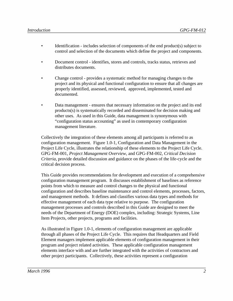
• Identification - includes selection of components of the end product(s) subject tocontrol and selection of the documents which define the project and components.
• Document control - identifies, stores and controls, tracks status, retrieves anddistributes documents.
• Change control - provides a systematic method for managing changes to theproject and its physical and functional configuration to ensure that all changes areproperly identified, assessed, reviewed, approved, implemented, tested anddocumented.
• Data management - ensures that necessary information on the project and its endproducts(s) is systematically recorded and disseminated for decision making andother uses. As used in this Guide, data management is synonymous with“configuration status accounting” as used in contemporary configurationmanagement literature.
Collectively the integration of these elements among all participants is referred to asconfiguration management. Figure 1.0-1, Configuration and Data Management in theProject Life Cycle, illustrates the relationship of these elements to the Project Life Cycle. GPG-FM-001, Project Management Overview, and GPG-FM-002, Critical DecisionCriteria, provide detailed discussion and guidance on the phases of the life-cycle and thecritical decision process.
This Guide provides recommendations for development and execution of a comprehensiveconfiguration management program. It discusses establishment of baselines as referencepoints from which to measure and control changes to the physical and functionalconfiguration and describes baseline maintenance and control elements, processes, factors,and management methods. It defines and classifies various data types and methods foreffective management of each data type relative to purpose. The configurationmanagement processes and controls described in this Guide are designed to meet theneeds of the Department of Energy (DOE) complex, including: Strategic Systems, LineItem Projects, other projects, programs and facilities.
As illustrated in Figure 1.0-1, elements of configuration management are applicablethrough all phases of the Project Life Cycle. This requires that Headquarters and FieldElement managers implement applicable elements of configuration management in theirprogram and project related activities. These applicable configuration managementelements interface with and are further integrated with the activities of contractors andother project participants. Collectively, these activities represent a configuration

Introduction GPG-FM-012
March 1996 3
management program applicable throughout the project life cycle. This Guide includesrecommendations for selecting the applicable configuration management elements for agiven program and/or project and for selecting the configuration management elementsthat should be included in contract vehicles.
Configuration management controls should be applied in a selective and graded manner. Guidelines for increasing levels of control are based on the health, safety, environmental,regulatory, cost and programmatic importance of the components, systems and products.
Implementation of configuration management guidelines should incorporate the use ofexisting procedures, programs, and processes. Wherever practical, configurationmanagement activities should be included as steps in procedures for related activities,rather than in stand-alone configuration management procedures, so the steps are integralto the process(es).
Configuration Management and Baseline Management
Within DOE, the terms "baseline management" and "configuration management" havebeen used with some degree of confusion. The purpose of this section is to clarify therelationship.
At any point in its life cycle, from inception to completion of the execution phase, aproject has a configuration. Initially, its configuration is a conceptual arrangement of theparts or elements of the desired end product(s). As the project proceeds through its lifecycle, the configuration is defined in greater detail through the design process anddocumented in specifications and drawings. At the end of the life cycle the configurationis the actual physical and functional configuration of the end product(s) and associated as-built documentation.
Configuration management is used to identify and document the configuration of the endproduct(s) and control changes to the configuration.
At selected points in a project’s life cycle, the current configuration is established as areference point or technical baseline. The technical baseline is combined with otherproject activities (e.g., activities to construct or activities to conduct remedial action) toform a scope baseline. The scope baseline is then used as a basis to develop project costand schedule baselines. The scope, cost, and schedule baselines serve as a basis forproject authorization, management, and as a standard for measurement

Figure 1.0-1CONFIGURATION AND DATA MANAGEMENT IN THE PROJECT LIFE-CYCLE
Pre-ConceptualActivities
ConceptualPhase
PreliminaryDesign
DetailedDesign
OperationsPhase
Construction Close OutPhase
Execution Phase
Functions &RequirementsBaseline
Design RequirementsBaseline
ConfigurationBaseline
As-Built ConfigurationBaseline
Document Control
Establish Identification, Change & Data Management Controls
Implement Identification,Change Control & Data Management
Design Control
Construction Change Control
Modification & Maintenance Change Control
p:\files\hill\graphics\cmf10-1.prs
Tur
nove
r
CD1
CD2
CD3
CD4
CD-1: Approval ofMission NeedCD-2: Approval ofBaselineCD-3: Approval ofStart Build/RemedialActionCD-4: Completion/Start of Operations

Introduction GPG-FM-012
March 1996 5
during the performance of a project. As such, the scope, cost, and schedule baselines arethe established plan against which the status of resources and the progress of a project aremeasured.
Baseline management is used to measure progress against and control changes to thescope, cost, and schedule baselines.
Configuration management and baseline management are integrated in that the baselinesare derived from the configuration and they share a common change control process.
The relationship between baseline management and configuration management isillustrated in Figure 1.1-1, Overview of the Change Control Process.

Figure 1.1-1
OVERVIEW OF THE CHANGE CONTROL PROCESS
P:\FILES\HILL\GRAPHICS\CMF11-1.PRS
*Baseline includes scope, schedule, and cost; technical is included in scope.
End
Baseline Management Configuration Management
Baseline Start*
Technical Impact?
END
No
Yes
BCP
TCP
Technical Start
No
Scope Impact?
Yes
BCP/TCPTCP
BCP
Baseline Change Proposal(BCP)

Principles and Processes GPG-FM-012
March 1996 7
2. PRINCIPLES AND PROCESSES
The focus of this Guide is on description of the end product(s) configuration (what iscontrolled), methods of controlling the configuration and related information (howcontrolled), and on the relationship of control elements to the Project Life Cycle (when). Section 2.1 provides an overview of the configuration management process followed byguidance, in section 2.2, on roles of different project participants. Sections 2.3, 2.6, 2.7and 2.8, provide detailed guidance applicable to programs, projects and operatingfacilities. Section 2.4 provides additional guidance specific to projects while section 2.5provides additional guidance for operating facilities. Six appendices provide aids, detailedguidance and examples to the program and project manager for implementing an effectiveconfiguration management program.
Table 2.0-1, Conventions, provides a listing of key terms and their meanings as used inthis Guide. The upper half of the table includes conventions for the different organizationsparticipating in DOE work; the bottom half provides conventions for different workscope.
2.1 Process Overview
Figure 2.1-1, Configuration Management Process Flow Diagram, depicts the overallconfiguration management process and process elements. In addition to the four keyelements of Identification, Document Control, Change Control, and Data Management;discussed in the introduction, Figure 2.1-1 includes the Change Implementation andReview process elements. Specific applicability of these processes to DOE programs,projects, and operating facilities is addressed in subsequent sections of this Guide. Ageneral description of these process elements is provided in the following paragraphs.
Identification . The process and methods of identifying components of the end product(s)(also referred to as configuration items) subject to control and the supportingdocumentation which defines the project and components. The supporting documentationincludes the numbers and other identifiers (e.g., document numbers, drawing numbers,equipment numbers) assigned to configuration items and documents, and the approvedtechnical documents that identify and define configuration items' functional and physicalcharacteristics, such as specifications, drawings, associated lists, and interface controldocuments.
Document Control. Provides for controlling the distribution of documents and approvedchanges and retains the master copy in storage for safekeeping. Document control alsomaintains distribution lists and a master controlled document index. The index includes

Principles and Processes GPG-FM-012
March 1996 8
information such as document title, document number, revision number or date of issue,and the document distribution list. Controlled distribution ensures that recipients ofcontrolled documents are notified of approved changes and that superseded documents arenot used for performing work.
Change Control. The process of managing proposed changes to the configuration itemsand technical documentation to ensure proposed changes are accurately described,systematically reviewed and evaluated for impact, properly implemented upon approval,and properly closed out. The change control process provides for technical, scope, cost,and schedule reviews of proposed changes. These reviews are documented as a changepackage. Upon completion of the necessary reviews, proposed changes are dispositionedby a Change Control Board (CCB). The CCB action is documented on the changeproposal or a change directive which provides instructions for implementation of approvedchanges.
Data Management and Reporting. The process of recording and reporting the currentstatus of configuration items, technical documentation, and all proposed and approvedchanges throughout the life cycle of the item. Data management satisfies two needs. Thefirst is to track the implementation of approved change proposals to ensure that allaffected documents are updated and that all change directive instructions are followed. This also permits the generation of reports providing the current approved configurationof configuration items and their documentation and pending changes to them. The secondneed is to create and maintain an audit trail of change proposals through the configurationchange control process. Chronological records of changes and reports can be prepared forany configuration item or baseline document.
Change Implementation. The process of making changes to the configuration items,technical documentation, and technical baselines.
• For configuration items, change implementation provides for verification that thephysical and functional characteristics of the configuration items conform to thetechnical documentation.
• For technical documentation, change implementation provides for verification thatthe technical documentation conforms to the technical baselines.
• For technical baseline documents, change implementation provides for verificationthat all technical and baseline documents impacted by the new baseline documentare updated.
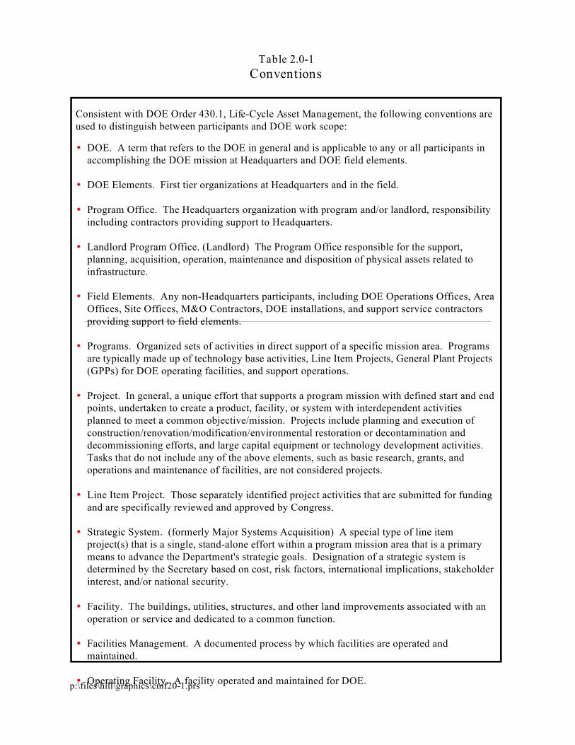
Table 2.0-1Conventions
p:\files\hill\graphics\cmf20-1.prs
Consistent with DOE Order 430.1, Life-Cycle Asset Management, the following conventions are used to distinguish between participants and DOE work scope:
DOE. A term that refers to the DOE in general and is applicable to any or all participants in accomplishing the DOE mission at Headquarters and DOE field elements.
DOE Elements. First tier organizations at Headquarters and in the field.
Program Office. The Headquarters organization with program and/or landlord, responsibility including contractors providing support to Headquarters.
Landlord Program Office. (Landlord) The Program Office responsible for the support, planning, acquisition, operation, maintenance and disposition of physical assets related to infrastructure.
Field Elements. Any non-Headquarters participants, including DOE Operations Offices, Area Offices, Site Offices, M&O Contractors, DOE installations, and support service contractors providing support to field elements.
Programs. Organized sets of activities in direct support of a specific mission area. Programs are typically made up of technology base activities, Line Item Projects, General Plant Projects (GPPs) for DOE operating facilities, and support operations.
Project. In general, a unique effort that supports a program mission with defined start and end points, undertaken to create a product, facility, or system with interdependent activities planned to meet a common objective/mission. Projects include planning and execution of construction/renovation/modification/environmental restoration or decontamination and decommissioning efforts, and large capital equipment or technology development activities. Tasks that do not include any of the above elements, such as basic research, grants, and operations and maintenance of facilities, are not considered projects.
Line Item Project. Those separately identified project activities that are submitted for funding and are specifically reviewed and approved by Congress.
Strategic System. (formerly Major Systems Acquisition) A special type of line item project(s) that is a single, stand-alone effort within a program mission area that is a primary means to advance the Department's strategic goals. Designation of a strategic system is determined by the Secretary based on cost, risk factors, international implications, stakeholder interest, and/or national security.
Facility. The buildings, utilities, structures, and other land improvements associated with an operation or service and dedicated to a common function.
Facilities Management. A documented process by which facilities are operated and maintained.
Operating Facility. A facility operated and maintained for DOE.

Figure 2.1-1CONFIGURATION MANAGEMENT PROCESS FLOW DIAGRAM
CHANGE PROPOSAL
ORIGINAL DOCUMENT
CONTROLLED DOCUMENT
DOCUMENTCONTROL
CHANGECONTROL
REVIEWS
IDENTIFICATION
CHANGEIMPLEMENTATION
DATA MANAGEMENT
&REPORTING
CHANGE PACKAGE
STATUS INFORMATION
CHANGE DIRECTIVE STATUS
INFORMATION
REPORTSBASELINE
DOCUMENTS
VERIFICATIONAND
VALIDATION
DOCUMENT
ENDUSER
P:\FILES\HILL\GRAPHICS\CMF21-1.PRS

Principles and Processes GPG-FM-012
March 1996 11
Reviews. The process of verifying: (1) the technical baselines satisfy the designrequirements, (2) the physical and functional characteristics of configuration itemsconform to the technical baselines, (3) approved changes have been properly incorporatedinto the technical baselines, (4) the as-built configurations conform to the approvedtechnical baselines, and (5) the entire configuration management program performs inaccordance with approved plans and procedures. Reviews are performed periodically tovalidate configuration documentation is properly updated and to verify only currentcontrolled configuration documents are being used.
2.2 Roles
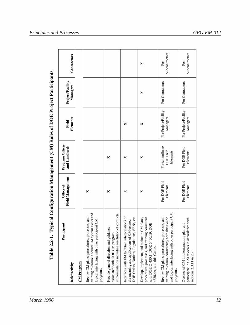
Configuration management should be an organizationally and procedurally integratedprogram. Typical roles of participants in DOE projects are shown in Table 2.2-1.
2.3 Guidelines for Programs, Projects, and Operating Facilities
This section includes guidelines common to programs, projects and operating facilities. Additional guidelines, specific to projects and operating facilities, are included in sections2.4 and 2.5, respectively.
2.3.1 Plans and Procedures
The configuration management process should be controlled by a configurationmanagement plan. For Line Item Projects, including Strategic Systems, the project shouldinclude a configuration management plan as a component of the project planningdocumentation. For other projects, use of a configuration management plan should beconsidered on a graded basis. Each non-DOE organization participating in the projectshould similarly be required to prepare and maintain a configuration management plan fortheir portion of the work that integrates with the project level plan. The project levelconfiguration management plan may be an integrated cohesive assembly of the plans ofother participants. The plan should include discussion of how configuration managementwill be conducted on the project and what items will be so managed. A suggestedconfiguration management plan is provided in Appendix A.
Procedures should be established by Program Offices, DOE Field Elements, and DOEcontractors for the control of changes to configuration items, baselines and supportingdocuments. Configuration management related procedures should incorporate existingprocedures, programs, and processes. Wherever practical, configuration managementactivities should be included as steps in procedures for related activities, rather than instand-alone configuration management procedures, so the steps are integral to theprocess(es).
Principles and Processes GPG-FM-012
March 1996 12
Tab
le 2
.2-1
. T
ypic
al C
onfig
urat
ion
Man
agem
ent (
CM
) R
oles
of D
OE
Pro
ject
Par
ticip
ants.
P
artic
ipan
t
Rol
e/A
ctiv
ity
Offi
ce o
fF
ield
Man
agem
ent
Pro
gram
Offi
ces
and
Land
lord
sF
ield
Ele
men
tsP
roje
ct/F
acili
tyM
anag
ers
Con
trac
tors
CM
Pro
gram
Rev
iew
CM
pla
ns, p
roce
dure
s, p
roce
sses
, and
trai
ning
to e
nsur
e a
soun
d C
M s
yste
m e
xist
s an
dlo
gica
l int
erfa
cing
with
oth
er p
artic
ipan
t CM
prog
ram
s.
X
Pro
vide
gen
eral
dire
ctio
n an
d gu
idan
ceas
soci
ated
with
DO
E C
M p
rogr
amim
plem
enta
tion
incl
udin
g re
solu
tion
of c
onfli
cts.
XX
Inte
rfac
es w
ith F
M to
obt
ain
inte
rpre
tatio
ns o
nth
e m
eani
ng a
nd a
pplic
atio
ns o
f CM
-rel
ated
DO
E O
rder
s, N
otic
es, R
egul
atio
ns, S
EN
s, e
tc.
XX
X
Dev
elop
, im
plem
ent,
and
mai
ntai
n C
M p
lans
,pr
oced
ures
, pro
cess
es, a
nd tr
aini
ng c
onsi
sten
tw
ith D
OE
O 4
30
.1,
DO
E 5
48
0.1
9,
DO
E43
30.4
A, a
nd th
is G
uide
.
XX
XX
X
Rev
iew
CM
pla
ns, p
roce
dure
s, p
roce
sses
, and
trai
ning
to e
nsur
e co
nsis
tenc
y w
ith th
is G
uide
and
logi
cal i
nter
faci
ng w
ith o
ther
par
ticip
ant C
Mpr
ogra
ms.
For
DO
E F
ield
Ele
men
tsF
or s
ubor
dina
teD
OE
Fie
ldE
lem
ents
For
Pro
ject
/Fac
ility
Man
ager
sF
or C
ontr
acto
rsF
orS
ubco
ntra
ctor
s
Ove
rsee
of C
M im
plem
enta
tion;
pla
n an
dpa
rtic
ipat
e in
CM
rev
iew
s in
acc
orda
nce
with
sect
ions
2.3
.11
& 2
.7.
For
DO
E F
ield
Ele
men
tsF
or D
OE
Fie
ldE
lem
ents
For
Pro
ject
/Fac
ility
Man
ager
sF
or C
ontr
acto
rsF
orS
ubco
ntra
ctor
s

Principles and Processes GPG-FM-012
March 1996 13
Principles and Processes GPG-FM-012
March 1996 14
Tab
le 2
.2-1
. T
ypic
al C
onfig
urat
ion
Man
agem
ent (
CM
) R
oles
of D
OE
Pro
ject
Par
ticip
ants
(co
ntin
ued).
P
artic
ipan
t
Rol
e/A
ctiv
ity
Offi
ce o
fF
ield
Man
agem
ent
Pro
gram
Offi
ces
and
Land
lord
sF
ield
Ele
men
tsP
roje
ct/F
acili
tyM
anag
ers
Con
trac
tors
Cha
nge
Con
trol
Pro
cess
Est
ablis
h an
d ap
prov
e ch
ange
con
trol
aut
horit
yth
resh
olds
for
scop
e, c
ost,
and
sche
dule
base
lines
.
XX
Eva
luat
e B
asel
ine
Cha
nge
Pro
posa
ls (
BC
Ps)
for
impa
ct o
n te
chni
cal,
scop
e, c
ost,
and
sche
dule
base
lines
. Dis
posi
tion
if im
pact
s do
not
exc
eed
chan
ge c
ontr
ol a
utho
rity
thre
shol
ds. P
rovi
deco
ntro
lled
dist
ribut
ion
of a
ppro
ved
chan
gedi
spos
ition
s to
all
affe
cted
par
ties.
Leve
l 1is
typi
cal
auth
ority
leve
l5
Leve
l 2is
typi
cal
auth
ority
leve
l4
Leve
l 2is
typi
cal
auth
ority
leve
l4
Leve
l 3is
typi
cal
auth
ority
leve
l4
Sub
mit
a B
CP
to th
e ne
xt h
ighe
r ap
prov
alau
thor
ity if
tech
nica
l, sc
ope,
cos
t, or
sch
edul
eim
pact
exc
eeds
cha
nge
cont
rol a
utho
rity.
Sub
mit
toLe
vel 0
auth
ority
Sub
mit
toLe
vel 1
auth
ority
Sub
mit
toLe
vel 1
auth
ority
Sub
mit
toLe
vel 2
auth
ority
Oth
er
Issu
e ba
selin
e do
cum
ents
, inc
ludi
ng c
hang
es,
and
mai
ntai
n th
e do
cum
ent m
aste
rs.
6Le
vel 1
Leve
l 2Le
vel 2
Leve
l 3
Not
ify th
e ne
xt a
utho
rity
leve
l CC
B th
at a
base
line
docu
men
t has
bee
n is
sued
.N
otify
Lev
el 0
auth
ority
Not
ify L
evel
1au
thor
ityN
otify
Lev
el 1
auth
ority
Not
ify L
evel
2au
thor
ity
Re
view
and
app
rove
saf
ety
syst
em c
lass
ifica
tion
crite
ria a
nd im
plem
enta
tion
plan
s fo
r D
OE
oper
atin
g fa
cilit
ies.
Land
lord
sX
Fac
ility
man
ager
sO
pera
ting
cont
ract
ors
Pre
pare
and
coo
rdin
ate
wor
k pl
ans
for
CM
im
plem
enta
tion
for
DO
E p
rogr
ams,
pro
ject
s, a
ndop
erat
ing
faci
litie
s un
der
thei
r ju
risdi
ctio
n.
X
Rev
iew
con
trac
tor
wor
k pl
ans
for
CM
impl
emen
tatio
n fo
r D
OE
pro
gram
s, p
roje
cts,
and
oper
atin
g fa
cilit
ies
unde
r th
eir
juris
dict
ions
.
XX
X

Principles and Processes GPG-FM-012
March 1996 15
2.3.2 Technical Baseline Identification
As discussed in section 1.1, the technical baseline is combined with other project activitiesto form the scope baseline. The scope baseline is the basis for cost and schedule baselines. The technical baseline defines the physical and functional configuration of the project’send product(s). Baseline management controls the scope, cost and schedule baselines andintegrates with configuration management which controls the technical baseline. Datamanagement controls information on the project and the configuration of its endproduct(s).
The technical baseline consists of a top-down set of requirements in which all subsidiaryrequirements flow down from the requirements above them. Typical DOE technicalbaselines are defined below. For identification and reference purposes, each update to thetechnical baseline has been given a title corresponding to its content and/or relationship inthe life cycle.
The titles may vary for a particular program and project and there may be fewer or morebaselines. For example the Tank Waste Remediation System, an EM Strategic System,has two program technical baselines (functional requirements and technical requirements)and five program element/project baselines: design requirements, design configuration, as-built configuration, operational, and decontamination. A minimum set of technicalbaselines would be those required to support scope, cost and schedule baseline submittalsfor Critical Decisions.
The relationship of these baselines to the Project Life Cycle is shown in Figure 1.0-1. Therecommended set of documents that should be included in each baseline is shown in Figure2.3-1, Typical Technical Baseline Documents.
Functions and Requirements Baseline. The initial baseline for projects, is developedduring the conceptual phase, and supports the Approval of Baseline Critical Decision. Itestablishes the functions and technical requirements of DOE programs and projects. Atthis stage of a project, the configuration represented by the baseline is conceptual withnothing designed or built. The functions and requirements baseline is generally developedas follows:
• The DOE mission and objectives are defined.
• Functions of the DOE programs are defined.

Principles and Processes GPG-FM-012
March 1996 16
• Functions of the DOE programs are allocated to technology base activities,facilities, and projects.
• Interfaces of the DOE activities, programs and projects with other facilities,programs and projects are identified.
• Further definition and requirements of the programs and projects are made.
Design Requirements Baseline. For complex projects, the design portion of theexecution phase is often split in to Preliminary Design and Detailed Design. Through thepreparation of preliminary planning and engineering studies, Preliminary Design translatesthe functions and requirements from the conceptual phase into preliminary drawings andoutline specifications, life-cycle cost analysis, preliminary cost estimates, and schedulingfor project completion. Preliminary Design identifies long lead procurement items andprovides analysis of risks associated with continued project development. At this stage ofa project, the configuration defined by the preliminary drawings and outline specificationsis represented by the Design Requirements Baseline with the following content:
• the physical systems for each project or facility are identified;
• the boundaries and interfaces for each physical system are identified;
• the major components for the physical systems are identified and defined and
• the functions and requirements, performance criteria, and constraints established inthe conceptual phase are allocated to the respective physical systems and majorcomponents.
Configuration Baseline. Represents the output of the detailed design portion of theexecution phase and supports the Approval of Start Build/Remedial Action CriticalDecision. The functions and requirements from the conceptual phase and the designrequirements from preliminary design, as applicable, are expanded to include the detailrequired to construct the systems and components of the end product(s). Theconfiguration of the project is defined by the design output documents which includeprocurement and construction specifications, drawings, test procedures, and operating andmaintenance information.
As-Built Configuration Baseline. At completion of the construction portion of theexecution phase, the detailed design documents established in the configuration baselineare used to establish the as-built configuration baseline as follows:

Principles and Processes GPG-FM-012
March 1996 17
• All changes occurring to the configuration baseline during construction areapproved and reflected in the as-built configuration baseline.
• All changes occurring to the configuration baseline during the operations phaseafter system turnover are approved and reflected in the as-built configurationbaseline.
2.3.3 Establishment of Baselines
Development of baselines for DOE programs, projects, and operating facilities shouldadhere to the following management concepts set forth by DOE O 430.1:
• identification, documentation, and approval of basic requirements;
• specification of a systematic process for development;
• formal identification and approval of baselines;
• specification of allowed variances from the approved baselines;
• regular reporting and assessment of status against the approved baselines; and
• corrective management action (that may include baseline revision) in the event avariance exceeds a prescribed threshold.
GPG-FM-016, Baseline Development, provides additional guidance in this area.
2.3.4 Change Control
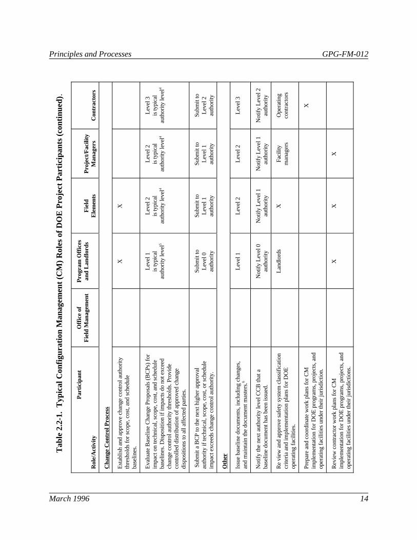
Technical baselines should be established and revised by submittal to the appropriate CCB. CCBs provide the coordination necessary to evaluate a change and assess its impact. Within DOE, the assignment of configuration change control responsibilities is generallybased on a hierarchy of classes of changes. Change classifications are specified levelsestablished for the control of changes affecting technical, scope, cost, and schedulebaselines. To ensure the flow-down of technical requirements, a proposed change to abaseline document, which could affect a higher-level baseline document, should bereferred to and acted upon by the higher level CCB first.
The CCB process is illustrated in Figures 2.3-2, Typical Change Control AuthorityHierarchy, and 2.3-3, Typical Change Control Hierarchy/Overview. Table 2.3-1 provides

Principles and Processes GPG-FM-012
March 1996 18
typical technical baseline change control approval criteria for the three change classes. Summary descriptions of the CCB hierarchy and the CCB Secretariat organization areprovided in this section. Change classifications, change control authority for scope, cost,and schedule baselines and the CCB Secretariat organization are described in greater detailin GPG-FM-009, Baseline Change Control.
2.3.4.1 Executive Baseline Change Control Board (Level 0)
The Executive Baseline Change Control Board (BCCB) is the Level 0 CCB. Membership,authority, and procedural requirements for the Executive BCCB are established by theSecretary. Membership of the Executive BCCB is the same as the Energy SystemAcquisition Advisory Board (ESAAB). Executive BCCB approval is normally requiredfor all critical decision points for Strategic Systems. Additionally, changes to the Level 0baseline exceeding established approval criteria (typical approval criteria are shown inTable 2.3-1) require Executive BCCB approval. The Level 0 scope, cost and schedulebaselines for projects are defined in their individual project planning documentationdeveloped in accordance with DOE Order 430.1. Only changes endorsed by the ProgramBCCB are presented to the Executive BCCB for action.
2.3.4.2 Program BCCB (Level 1)
Membership, authority, and procedural requirements for the Level 1 Program BCCBshould be established in BCCB Charter for each DOE program. Membership shouldinclude representatives from the engineering, safety and health, environmental, and qualitydisciplines as well as management, operations, and maintenance representatives. Responsibility for chairing the Program BCCB (Level 1) is generally held by the AssistantSecretary or the Deputy Assistant Secretary for the program. The Program BCCB shouldhave change authority over all Class 1 changes. Class 1 changes are changes that haveimpacts which exceed Class 2 and Class 3 approval criteria (typical approval criteria areshown in Table 2.3-1).
2.3.4.3 Field Element CCBs (Level 2)
Membership, authority, and procedural requirements for Level 2 CCBs should beestablished in Field Element configuration management plans and change controlprocedures. These documents and procedures should establish approval criteriarequiring Level 2 CCB approval for changes to project scope, cost, and schedulebaselines. Membership should include representatives from the engineering, safety andhealth, environmental, and quality disciplines as well as management, operations, andmaintenance representatives. Level 2 CCBs should have change authority over all Class 2

Principles and Processes GPG-FM-012
March 1996 19
changes. Class 2 changes are changes that impact interface control documents or that havescope, cost, or schedule impacts that exceed Class 3 approval criteria (typical approvalcriteria are shown in Table 2.3-1).
2.3.4.4 Contractor CCBs (Level 3)
Membership, authority, and procedural requirements for Level 3 CCBs should beestablished in contractor configuration management plans and change control procedures. These plans and procedures should be reviewed by the Field Element to ensure they areconsistent with the Field Element configuration management planning documents andchange control procedures. Membership should include representatives from theengineering, safety and health, environmental, and quality disciplines as well asmanagement, operations, and maintenance representatives.
2.3.4.5 CCB Secretariat Organization
Typically, baseline management change control is administered at each level by asecretariat which performs its administrative functions in compliance with configurationmanagement plans and change control procedures. A secretary is assigned to each CCBby the chairperson of the respective CCB. Level 3 CCBs should have change authorityover all Class 3 changes. Class 3 changes are changes to contractor-controlled design-input or design-output documents, including software revisions to configurationidentification computer codes, that do not exceed Class 3 approval criteria (typicalapproval criteria are shown in Table 2.3-1) or affect any other contractor.
The CCB secretariat administers the change control process, provides agendas anddocuments to board members prior to meetings, and documents and disseminates boarddirection and decisions to all affected activities. Each CCB secretary provides periodicstatus reports to their respective CCB chairperson.
2.3.5 Configuration Identification
The sites, facilities, structures, systems and components of DOE projects, programs andoperating facilities that are important to the environment, safety and health and otherstructures, systems and components that are deemed critical to the DOE mission should beincluded in the configuration management program. The configuration items should beidentified in the technical baseline documentation and should have a unique identifier (e.g.,component or equipment number). The unique identifier is needed to ensure consistency,retrievability, and traceability of technical and baseline documentation for configurationitems. For DOE, the configuration identification guidelines apply specifically to:

Figure 2.3-1
TYPICAL TECHNICAL BASELINE DOCUMENTS
FUNCTIONS AND REQUIREMENTS BASELINE:
Strategic PlansProgram PlansMission Need JustificationConceptual Design ReportsProject Execution PlansInterface Control Documents
DESIGN REQUIREMENTS BASELINE:
Design CriteriaPreliminary Safety Analysis ReportsSystem RequirementsConceptual DesignPreliminary DesignInterface Control Documents
CONFIGURATION BASELINE:
Final Safety Analysis ReportsDefinitive (Final) DesignOperational Safety RequirementsSpecificationsDrawingsQuality Assurance ProceduresTest ProceduresOperating and Maintenance ProceduresProcurement DocumentsWork Control PackagesOperating and Maintenance ManualsConstruction Procedures
AS-BUILT CONFIGURATION BASELINE:
Configuration Baseline documents with the approved updates incorporated to reflect the actual physical configuration.
P:\FILES\HILL\GRAPHICS\CMF23-1.PRS
Note: The above includes computer hardware and software subject to configuration management

Principles and Processes GPG-FM-012
March 1996 21
• physical items (i.e., facilities, structures, systems, and components [SSCs]);
• software;
• site characteristic data and samples;
• waste package; and
• documentation (including supporting analysis and data).
The level of identification required varies depending on the importance of theconfiguration item and the indentured level from which documentation needs to beretrieved. Structures, systems and components important to safety require a more detailedidentification than other SSCs to ensure traceability of requirements throughout the life ofthe project, program or operating facility. Appendix B provides additional guidelines forconfiguration identification and Appendix F provides an example from DOE’s YuccaMountain Project.
2.3.6 Traceability
Configuration management should require traceability of technical baseline requirementsand data through all phases of DOE programs, projects and operating facilities. Technicalbaseline documents should establish traceability of requirements through all levels ofdocumentation, and to the configuration items. Regulatory and other design basisrequirements depicted in documents which describe configuration items should be readilytraceable to their origin through design requirements documents, etc.
The baselining process allocates technical requirements to subsequent levels of detail. Throughout the design, construction and operations phases, materials and componentsshould be traceable to their application and physical location. Traceability of technicalrequirements should be established by uniquely identifying configuration items and theassociated documentation. Data management systems should be utilized to crossreference the appropriate documents to configuration items.
2.3.7 Software Configuration Management
The configuration management program should require that critical computer softwareand associated documentation be identified and controlled. Software designated to becontrolled should be uniquely identified and established as part of the technical baseline. Guidance for computer software change control is provided in section 2.6 of this Guide. Software that should be included in the configuration management program includes:

CLASS 3
CLASS 2
CLASS 1
Figure 2.3-2
TYPICAL CHANGE CONTROL AUTHORITY HIERARCHY
EXECUTIVE BCCB
(LEVEL 0)
PROGRAMBCCB
(LEVEL 1)
FIELD ELEMENT
CCBs(LEVEL 2)
CONTRACTORCCBs
(LEVEL 3)
P:\FILES\HILL\GRAPHICS\CMF23-2.PRS

ChangeClass
ChangeClass
ProgramInitiates
BCP Form*
Field ElementInitiates BCP
Form*
ContractorInitiatesChange
Proposal Form
ProgramLevel 1 BCCB
Approval
Field ElementLevel 2 CCB
Approval
ContractorLevel 3 CCB
Approval
ChangeClass
ChangeClass
ChangeClass
ImplementChange
IncorporateChange
CloseChange
ExecutiveLevel 0 BCCB
Approval
0 & 1
2 & 3
0, 1 & 2
3
0
1
0 & 1
2
0, 1 &
3
* Or EquivalentP:\FILES\HILL\GRAPHICS\CMF23-3.PRS
Figure 2.3-3TYPICAL CHANGE CONTROL HIERARCHY/OVERVIEW

Principles and Processes GPG-FM-012
March 1996 24
Table 2.3-1. Typical CCB Approval Criteria for Baselines.
ChangeLevel Baseline Documents
0 • BCPs and requests for deviations or waivers that affect Level 0 requirementsESAAB BCCB
1 • Functions and requirements baselineProgram • Document change proposals and requests for deviations or waivers that affect Level 1BCCB functions and requirements baseline
• Directed changes resulting from DOE policy directives and regulatory or statutoryrequirements that affect baselines1
• Proposed changes to lower-level baselined documents that Program-level baselinedocuments
• Proposed Level 0 changes initiated at the Program level
2 • Design requirements baselineField Element • Configuration baselineCCBs • As-Built Configuration baseline
• Revisions and requests for deviations or waivers that affect Level 2 requirements• Field changes that affect Level 2 requirements baselines• Directed changes resulting from DOE policy directives and regulatory or statutory
requirements that affect baselines1
• Proposed Level 1 changes initiated at the Field Element level• Proposed changes to lower-level baselined documents that project-level baseline
documents
3 • Design requirements baselineContractor CCBs • Configuration baseline
2
2
• As-built configuration baseline2
• Revisions and requests for deviations or waivers that affect Field Element levelrequirements baselines2
• Field changes that affect Field Element level requirements baselines2
Directed changes are not approved by the CCB but should be reviewed for impact.1
Within the approval criteria as defined by the Field Element.2

Principles and Processes GPG-FM-012
March 1996 25
• operations and process control;
• protection systems;
• engineering development, design analyses, evaluation, and assessment;
• mathematical models;
• data base or document indexes when used as the controlled source of informationfor the above; and
• computer aided design/manufacturing/engineering (CAD/CAM/CAE).
2.3.8 Interface Control
The functions, requirements, and physical characteristics of the end product(s) at commonboundaries among project participants need to be identified, documented and controlled. For complex projects, Interface Control Working Groups should be established to identify,document, and monitor interfaces. Interface Control Documents should be used to defineinterfaces, interface responsibilities, and interface requirements in terms of functions,requirements and physical characteristics, as appropriate, and interface constraints andassumptions. For changes that affect functions, requirements and physical characteristicsthat exist at a common boundary between two configuration items which are controlled bydifferent organizations, the Interface Control Documents should also include interfacecontrol drawings. The Interface Control Documents should be baselined by theappropriate CCB. Detailed guidelines for interface control are given in GPG-FM-13,Interface Management.
2.3.9 Data Management
Computerized information applications should be used to collect, store, and maintainconfiguration management technical baseline information and changes thereto. Whenused, the design, development, implementation, and use of these applications should besubject to the guidelines of the configuration management program.
New facilities should develop a Master Equipment List (MEL) data base during designand construction. This list should contain structures, systems and components (SSCs)selected by the Field Element and the contractor based upon safety grades assigned to theSSCs. The list should have the following features, as a minimum:

Principles and Processes GPG-FM-012
March 1996 26
• All SSCs should be classified (where applicable) by engineering system, start-upsystem, operating system, safety class, hazard category, instrument loop number,piping line number, circuit number, plant location, applicable Work BreakdownStructure (WBS) element, and any other category of interest to the users of theMEL.
• SSC lists should be extractable by category, for example, a list of all Safety Class 1items.
• Each SSC should reference its unique identification number, engineering drawingor specification number, and other related documents, for example, applicableSafety Analysis Reports (SARs), Interface Control Document, spare parts list, andtest procedure.
• Operating and maintenance procedures should be cross-referenced to theirassociated SSCs and operating systems as applicable.
• Each existing facility classified as a Hazards Category Class 3 or higher shoulddevelop a Safety Equipment List (SEL) for Safety Class 1 equipment only. TheSEL should contain the data specified above and should be a subset of the MEL.
Detailed guidelines for configuration management related computer applications areprovided in Appendix C. Appendix F, DOE’s Yucca Mountain Project ConfigurationIdentification Plan, provides a good example of determining safety grades and includes anevaluation of configuration information system needs which identifies six benefits that areuniversal in their applicability.
2.3.10 Reporting
Reporting processes should meet the guidelines of GPG-FM-006, Performance Analysisand Reporting; GPG-FM-009, Baseline Change Control, and GPG-FM-010, ProjectExecution and Engineering Management Planning.
2.3.11 Reviews
Assessments should be performed to measure the effectiveness of the configurationmanagement process, and consistency between the project physical system and thedocumentation that represents that system. Contractor assessment and surveillance resultsand corrective actions should be reviewed by the Field Element.
Principles and Processes GPG-FM-012
March 1996 27
2.3.11.1 Programmatic Assessment
Programmatic assessments should determine the acceptability of the configurationmanagement process and implementation of the requirements contained in projectexecution and planning documentation. Initially, assessments should identify weaknessesof procedures and necessary corrective actions. Subsequent assessments should determinethe effectiveness of corrective actions and continue to monitor and continuously improvethe configuration management process.
2.3.11.2 Physical Configuration Assessments
Physical configuration assessments should determine the consistency between thedocumented technical baseline and the actual physical configuration. Discrepancies shouldbe analyzed and appropriate corrective action taken to resolve them. These assessmentsshould be performed periodically. An annual schedule for the physical configurationassessments should be prepared by the contractor and submitted as an integral part of thework planning documentation.
Configuration verification processes should meet the guidelines of GPG-FM-005, Test andEvaluation; GPG-FM-010, Project Execution and Engineering Management Planning;GPG-FM-015, Project Reviews; and GPG-FM-029, Systems Analysis and Assessment.
2.3.12 Control of Deviations and Waivers
Deviations and waivers are approved exemptions from a particular requirement of thecurrent approved configuration for a specific case or a specified period of time. Deviations relate to variation from approved requirements prior to development orconstruction of the item; waivers relate to variations after the item has been developed orconstructed. Deviations and waivers differ from approved engineering changes in thatthey do not require a change to the current approved configuration. Deviations andwaivers should be minimized and only granted when there is an overriding benefit. Adeviation may be processed in lieu of a change to the baseline when it is necessary todepart from a mandatory design requirement in a specific application but it is not desirableto change the design. A proposed deviation should be converted to a design change if it isdetermined that the deviation results in a superior design. If an item has departed fromspecified requirements but is considered suitable for use or for being repaired by anapproved method, a waiver should be processed in accordance with applicable procedures. The deviation and waiver documents should be maintained as records to showauthorization for the as-built condition to vary from the documented design requirements.

Principles and Processes GPG-FM-012
March 1996 28
2.3.13 Waste Inventory Configuration
Where applicable, waste inventory should be controlled in a manner similar to thetechnical baseline. The inventory configuration should provide the consistent andapproved information needed for the technical planning and engineering required toremediate the waste. This inventory configuration used for technology selecting andengineering design should be referenced in the design basis documentation. The followingrequirements should apply.
• A waste inventory data base should contain location, properties (physical,mechanical, thermal), composition (chemical, radiological), and quantity (volume,weight) information. As characterization of waste proceeds, the approved resultsshould be added to this data base. Where specific properties do not exist, thosefacts should be included in the inventory data base such that the data base shouldconvey information about what is, and is not known, about the inventory.
• The inventory components should contain information regarding the date when thecomponent was measured, the source report the measurement, and the qualitylevel of the measurement (conceptual estimate or actual physical measurement).
• A single, controlled waste inventory data base should provide the approved sourceof inventory data.
• Changes to the waste inventory should be communicated to a controlleddistribution to ensure that the appropriate users have up-to-date inventoryinformation.
• All inventory data should be checked to ensure internal consistency (e.g., for wastetransferred from Tank A to Tank B, the inventory should show an increase in TankB with a corresponding decrease in Tank A). Data base integrity should bepreserved to ensure that data contained therein is entered, changed, or deleted onlyby authorized personnel and meets all other data protection policies.
• Changes to the inventory should be traceable.
• A method should be established to include projections of future waste additions. These projections should also be subject to configuration control.
• System-generated waste inventory should be linked to the physical systemconfiguration that produces the waste.

Principles and Processes GPG-FM-012
March 1996 29
• The configuration-controlled waste inventory should be used to support requiredenvironmental and safety reporting.
Appendix B includes guidance on configuration identification for waste characterizationdata samples and waste packages.
2.4 Additional Guidelines for Projects
2.4.1 Establishment of the Technical Baseline for Projects
For DOE projects, the development of the technical baseline is an iterative processthrough successively more detailed stages as illustrated in GPG-FM-016, BaselineDevelopment, and Section 3.2 of GPG-FM-010, Project Execution and EngineeringManagement Planning. Each successive baseline extends and expands on thedocumentation described in the previous baseline(s). The technical baseline is establishedin accordance with DOE O 430.1, controlled through the baseline change control processand approved and released through the appropriate CCB.
2.4.2 Change Control for Projects
This subsection describes the recommended process for changing the approved technicalbaselines. The configuration control process ensures that changes to technical baselinesare properly executed using the following process.
• Using standardized change proposal forms for initiation, submittal, and approval ofchanges.
• Reviewing changes to ensure that the change is necessary and that the propertechnical approach is described.
• Performing impact evaluations by DOE organizations that are potentially affected.
• Ensuring changes are dispositioned by the appropriate CCB.
• Maintaining auditable and traceable documentation for CCB evaluations,comments and decisions.
• Providing information copies of CCB meeting minutes and approved changeproposals to the next higher level Secretariat.
Principles and Processes GPG-FM-012
March 1996 30
• Ensuring implementation of the change is done in a timely and controlled manner.
• Accomplishing any necessary training associated with a change.
• Verifying adequate closeout of the change.
Figure 2.4-1, Overview of the Technical Baseline Change Control Process, and Figure2.4-2, Technical Baseline Change Control Process Flow Chart for Projects, present anoverview of the DOE project change control process described below:
2.4.2.1 Change Initiation and Submittal
A change proposal may be initiated by any individual participating in DOE activities. Achange proposal identifies affected technical baselines and technical documents. Theinitiator should perform an initial evaluation of the potential impact of the proposedchange. This initial evaluation should identify, to the extent possible, all documents anddata bases which need to be updated to reflect the proposed change. Additionally, theproposed change should be evaluated to ensure that adequate justification is provided formaking the change and that the proper technical approach is described.
Proposed changes should be submitted to the appropriate CCB Secretariat (e.g., ifinitiated by a Field Element, the change proposal would be submitted to the Field ElementCCB Secretariat). Proposed change proposals should be submitted on a BCP orequivalent form in accordance with requirements established in project execution planningdocumentation. Upon receipt of a change proposal, the CCB Secretariat: should review itfor completeness; if complete, the Secretariat should log the change proposal, assigning ita unique number; and distribute it to all affected organizations for review and comment.
2.4.2.2 Change Review and Impact Evaluation
Affected organizations should review and evaluate the proposed change to determine if: (1) the change is necessary, (2) the technical approach is adequate and complete, and (3)the technical, scope, cost and schedule impacts are identified. The cognizant CCBSecretariat should compile and coordinate comment resolution and distribute a changepackage for review by the CCB members prior to CCB disposition. The change packageshould include, as a minimum, the change proposal, reviewers comments and commentresolutions.
The CCB evaluation addresses the options of making or not making the proposed change. Changes should be limited to those that:

Principles and Processes GPG-FM-012
March 1996 31
• correct deficiencies, including safety deficiencies;
• offer a significant improvement in performance or functionality;
• effect substantial capital and life-cycle cost savings;
• prevent slippage in an approved schedule; or
• implement approved changes to other portions of the scope, cost, and schedulebaselines or the DOE Strategic Plan.
The technical approach should be reviewed for adequacy and completeness of necessarychanges. Additionally, the evaluation should review the proposed change to ensurecompliance with the technical baseline and identify the documents and data bases (e.g.,design criteria, training, and interface documents), for which they have responsibility,which are affected by the proposed change. This information is included as part of thechange package. This evaluation should also include reviews for impact on cost andschedule baselines.
The estimated cost of each change should be identified with the appropriate WBSelement(s). Supporting cost data at the next-lower level of the WBS should be supplied torelate the significant cost elements to the principal elements of the proposed change.
Projects within existing operating facilities and projects in the execution phase shouldperform technical reviews in accordance with applicable guidance provided in section 2.7.
2.4.2.3 Change Disposition
Proposed changes may be canceled/withdrawn, deferred, disapproved, approved withconditions, or approved by the applicable CCB. The CCB Chairperson should have fulldecision making authority as the CCB is an advisory, not a voting board. In their advisorycapacity and for their individual areas of technical responsibility and expertise, each boardmember assures the chairperson that everything has been addressed that should beaddressed. At the discretion of the CCB Chairperson, change proposals may bedispositioned without conducting a board meeting. Only those changes that are approvedchanges or approved with conditions should be implemented. Proposed changes may becanceled/withdrawn by the originator with CCB approval.

Principles and Processes GPG-FM-012
March 1996 32
2.4.2.4 Directed Changes
For directed changes, such as DOE directives or budget adjustments, the directive is theauthorization for implementing the change. However, the baseline change control processshould be followed to ensure all impacts of the directed change are identified. Theresponsible Program Office manager should forward a copy of the directive to theresponsible Field Element manager. The Field Element manager should prepare andprocess a BCP for the directed change in accordance with the guidelines of this section.
2.4.2.5 Change Implementation
Implementation of changes may include physical changes in addition to documentationchanges. Change implementation involves the following considerations.
• If the change proposal requires physical implementation, it should be completedusing the Field Element work plan process. Revisions to the approved changeproposal required during physical implementation should be subject to the samerequirements applied to the initial request.
• Upon completion and acceptance of the physical change (or after approval of thechange proposal if no physical implementation is required) affected documents anddata bases should be updated in a timely manner but, not until the physicalimplementation has been completed and accepted.
• Limits should be established for the maximum number of outstanding changeswhich can exist against a given document and the maximum time duration betweenapproval or implementation of the change and incorporation into the affecteddocuments. Typical limits for documents not required by operators are 5 changesor 6 months.
• Field Element procedures should establish responsibilities for physicalimplementation of changes, updating affected documents and data bases, andverification of completion of the change. The implementing organization(s) shouldverify that necessary action is completed within the time frames set forth in thechange authorization document.
2.4.2.6 Training
Program Office and Field Elements should develop and implement a training program that(1) provides for understanding and proper implementation of the configuration
Principles and Processes GPG-FM-012
March 1996 33
management program guidelines and procedures and (2) ensures that appropriate facilityoperation and maintenance personnel are familiar with modified systems and equipment.

BCPs ANDDIRECTEDCHANGES
CHANGE TOCONFIGURATION
BASELINE?
CHANGE TOFUNCTIONS &
REQUIREMENTSBASELINE?
ESTABLISH DESIGN REQUIREMENTS BASELINE
ESTABLISH FUNCTIONS &REQUIREMENTS BASELINE
OBTAIN PROGRAM(LEVEL 1) BCCB
APPROVAL TO REVISEBASELINE
OBTAIN FIELD ELEMENT(LEVEL 2) CCB
APPROVAL TO REVISEBASELINE
ESTABLISH CONFIGURATION BASELINE
CONSTRUCT
ESTABLISH & MAINTAINAS-BUILT CONFIGURATION
BASELINE
OBTAIN CONTRACTOR(LEVEL 3) CCB
APPROVAL TO REVISE
BCPsDIRECTEDCHANGES &CPs
CPs, FIELDCHANGESMODIFICAITONS,DEVIATIONS &WAIVERS
TEMPORARY MODIFICATIONS, SET POINT CHANGES, NOT
LIKE-IN-KIND REPLACEMENTS, ETC.
CHANGE TODESIGN
REQUIREMENTSBASELINE?
Figure 2.4-1OVERVIEW OF THE TECHNICAL BASELINE CHANGE CONTROL
PROCESS
NOTE: Operating facilities obtain line management approval instead of Level 1 & Level 2 CCB approval for revisions to Design Requirements and higher technical baselines.P:\FILES\HILL\GRAPHICS\CMF24-1.PRS
NO
YES
NO
YES
NO
YES

NO
Initial TechnicalBaselineEstablishment
CP, BCP, Directed Change, Deviation, Waiver, etc.
YES
SecretariatReceipt andReview for
Completeness
Return toOriginator
Complete?
Assign UniqueNumber &
Enter in BCCBLog
Distribute forReview andComment
Compile andCoordinateCommentResolution
Prepare andDistributePre-BoardPackage
SecretariatDistributesApproved
BCP
CognizantOrganizationImplements
BCP
CognizantManagerPerforms
Verification
SecretariatUpdates
BCCB Log
RequireHigher Level CCB/BCCB
Approval
CCBApproval
Higher Level CCB/BCCB
Approval
Forward toHigher Level
CCB/BCCB forAction
SecretariatNotify Originator
& UpdateBCCB Log
NO
NO
NO
YES
YES
YES
Figure 2.4-2TECHNICAL BASELINE CHANGE CONTROL PROCESS FLOWCHART
FOR PROJECTS
P:\FILES\HILL\GRAPHICS\CMF24-2.PRS
A
A
Affected Organizations
Review, Evaluate, & Comment

Principles and Processes GPG-FM-012
March 1996 36
Training programs should be updated and performed using revised documents that reflectapproved changes. Training programs should be updated in the following manner.
• Organizations responsible for the training should receive the revised documentsearly enough to evaluate and incorporate changes into training materials.
• Revised documents should be evaluated to determine what changes should bemade to the training material.
• Training materials should be revised and training conducted.
2.4.2.7 Change Closeout
Change closeout should not occur until: (1) the physical change or technical documentchange has been completed, tested (physical changes), and accepted; (2) all affecteddocuments and data bases have been updated to correctly reflect the change; and (3) anynecessary training has been completed. Upon completion of implementation, verification,acceptance and training, change implementation should be verified to ensure eachimplemented change is complete and in compliance with the approved change documents. After verification is complete, the CCB Secretary should be notified for update of theBCCB log. The change proposal or BCP should be closed and submitted as a record inaccordance with approved records management procedures.
2.4.2.8 Change Tracking
All changes should be tracked from the submittal of a change proposal throughassessment, disposition, implementation and closeout. The tracking process should beinitiated upon assignment of a change proposal identifier, and should provide the currentstatus of any change proposal at all times. Upon completion of implementation ofapproved changes, the implementing organization should notify the Secretary of the CCBwhich authorized the change for update of the BCCB log.
2.5 Additional Guidelines for Operating Facilities
In addition to the guidance provided herein, there are a number of DOE rules, orders andstandards applicable to DOE nuclear facilities that contain requirements and guidancerelated to elements of configuration and data management. The most significant of these,from a configuration and data management viewpoint are: DOE O 4330.4A, CONDUCTOF MAINTENANCE AT DOE FACILITIES; DOE O 5480.19, CONDUCT OFOPERATIONS AT DOE FACILITIES; DOE-STD-1073-93, Guide for Operational

Principles and Processes GPG-FM-012
March 1996 37
Configuration Management Program; and DOE-STD-1027-92, Hazard Categorizationand Accident Analysis Techniques for Compliance with DOE Order 5480.23.
There may appear to be redundancy between this Guide and DOE-STD-1073-93, Guidefor Operational Configuration Management Program. However, the standard predatesissuance of DOE O 430.1, and many DOE projects are performed for or within existingfacilities. Configuration and data management for operating facilities are addressed hereto provide continuity with the life-cycle approach of DOE O 430.1 and its family ofimplementing Guides.
2.5.1 Establishment of the Technical Baseline for Facilities
Technical baselines for DOE facilities should be developed in accordance with DOE O430.1 during the design and construction of each facility and maintained. However, forfacilities where the technical baseline has not been consistently updated to reflect changesto the physical and functional configuration of the existing structures, systems,components, products and supporting documentation, a limited baseline reconstitutionprogram should be implemented. DOE-STD-1073-93 provides extensive guidelines fordesign reconstitution programs.
When baseline reconstitution is required, facility management should ensure viabledocument control and change control processes are in place and develop animplementation plan which reflects the safety system classification and grading approachdiscussed below. The technical baseline should be re-established as follows:
• Safety System Classification/Grading Criteria. Systems and componentsshould be classified by their safety, operability, and reliability significance to health,safety and the environment. For example, a fluid system carrying high heat wasteis more significant than a domestic water system. Therefore, the heat wastesystem would have a higher priority for baseline reconstitution and subsequentdesign changes would be more closely reviewed. A safety classification systemshould be used as part of technical baselining to classify systems. Once systemsare classified, a graded approach to baseline reconstitution and change controlshould be applied.
• As-Built Configuration Baseline. Facility walkdowns should be performed todetermine the current, as-built, condition of facilities. The as-built conditionsshould serve as the starting point for technical baseline reconstitution. Aswalkdowns are performed, an MEL (see section 2.3.9) should be generated. Following the walkdowns:

Principles and Processes GPG-FM-012
March 1996 38
• component numbers should be assigned/updated,• components should be labeled,• drawings should be revised or created,• spare parts support should be verified/initiated,• operator sketches should be revised or created,• operating procedures should be revised,• maintenance procedures should be revised,• training requirements should be revised, and• instruments and setpoints should be identified and verified.
• Design Requirements Baseline. Once the as-built configuration is known, asystem-by-system technical evaluation should establish the design requirementsbaseline by verifying the as-built configuration correctly represents designrequirements. As part of this analysis, the systems and components should beclassified using the previously developed grading criteria.
• Functions and Requirements Baseline. The technical evaluation to establish thedesign requirements baseline should also establish the functions and requirementsbaseline by verifying that the design requirements baseline documents correctlyrepresent established functions and requirements, performance criteria andconstraints.
• For discrepancies between the as-built configuration and design documentationidentified during baseline reconstitution, new documentation should be developedor equipment modified for the most critical equipment.
• The calculations, evaluations and analysis performed as part of the technicalbaseline reconstitution should be documented and maintained as baselinedocumentation. The records management system should control these recordswhich serve as the basis for evaluation of subsequent design change proposals.
• Where applicable, the requirements of DOE O 5480.5, SAFETY OF NUCLEARFACILITIES; DOE O 5480.21, UNREVIEWED SAFETY QUESTIONS; DOE O5480.22, TECHNICAL SAFETY REQUIREMENTS; DOE O 5480.23,NUCLEAR SAFETY ANALYSIS REPORTS; and DOE O 5700.6C, QUALITYASSURANCE; as well as 10 CFR 830.120, Quality Assurance Requirements,should be incorporated into the baseline reconstitution program.
• The order and extent of baseline reconstitution should be based on considerationsof nuclear safety, environmental safety, DOE mission, industrial safety, and other

Principles and Processes GPG-FM-012
March 1996 39
concerns, including financial. Baseline reconstitution to confirm the adequacy ofnuclear safety-related systems and at the interfaces between existing facilities andnew project construction should receive priority attention.
• When baseline reconstitution is completed, the baseline documentation shouldrevert to normal baseline and configuration management controls.
2.5.2 Operating Facility CCBs
Each operating facility should establish a Level 3 CCB with the authority to review andapprove change proposals. For facilities where a graded approach determines that a CCBis not warranted, a change control authority should be established that fulfills the functionsof the CCB. Each CCB should include, as a minimum, representatives from theengineering, safety and health, environmental, and quality disciplines as well as theoperations and maintenance departments and project management. The operating facilityCCB should have jurisdiction on all Class 3 changes. The CCB should also be responsiblefor the correct functioning of the configuration management processes within the facilityto ensure:
• the facility's technical baselines satisfy the design requirements;
• the physical and functional characteristics of configuration items conform to thetechnical baselines;
• Approved changes have been properly incorporated into the technical baselines;
• the facility's as-built configuration conforms to the approved technical baselines;and
• the entire configuration management program performs in accordance withapproved plans and procedures.
Change proposals exceeding Level 3 approval criteria (see Table 2.3-1 for typical approvalcriteria) should be approved by the appropriate level of DOE line management. CCBs andBCCBs above Level 3 are not normally used for operating facilities. Budget changeproposals (which may result from directed changes from the Program Office or fromrequests from contractors) should be dispositioned by the Field Element manager if thechange to the scope, cost or schedule baselines does not exceed approved thresholds. Allrecommended changes to the technical baseline exceeding the thresholds identified for theField Element should be submitted to the Program Office with Field Element endorsement.

Principles and Processes GPG-FM-012
March 1996 40
When required, the Program Office director should obtain the Assistant Secretary orDeputy Assistant Secretary's disposition. The change control program for operatingfacilities should be administered by a secretariat organization as described in a previoussection of this Guide.
2.5.3 Work Control
Work control is the process by which work at operating facilities is initiated, approved,performed, verified, and documented. Configuration change control often overlaps andinteracts with work control processes. DOE 4330.4A establishes work controlrequirements for maintenance activities. DOE 5480.19 establishes work controlrequirements for operations that interface with and overlap with configuration changecontrol and maintenance work control. Each operating facility should develop procedureswhich integrate these interfacing and overlapping requirements. Typically, the facility'swork control process is used as the method to address all of the applicable elements.
Figure 2.5-1, Typical Work Control Process, illustrates the typical work control process. Shaded areas identify the configuration change control elements of the work controlprocess.
2.5.4 Change Control for Operating Facilities
For operating facilities, a configuration change is any modification to the technicalbaselines, the facility's configuration or the operating procedures and limits. Configurationchange control should ensure (1) all proposed changes are reviewed against baselinedocumentation and (2) all affected elements of the technical baseline are updated asneeded. DOE O 5480.19 and DOE O 4330.4A include requirements for configurationmanagement processes. Additionally, this Guide provides recommendations for(1) modification control, (2) temporary modification control, (3) setpoint control,(4) computer software control, (5) technical reviews, and (6) document control forconfiguration management. Table 2.5-1, Configuration Management Requirements andGuidelines for DOE Operating Facilities, identifies applicable requirements and guidanceof DOE 5480.19, DOE 4330.4A, and this Guide for DOE operating facilities. Figure 2.5-2, Technical Baseline Change Control Process Flow Chart for Operating Facilities,presents an overview of the change control process described in the following subsections.
2.5.4.1 Change Initiation and Submittal
A change proposal may be initiated by any individual participating in DOE activities. Achange proposal identifies affected technical baselines and technical documents. Change

Principles and Processes GPG-FM-012
March 1996 41
proposals for facility modifications, setpoint changes, and computer software changesshould be initiated in accordance with the guidelines of sections 2.5.5, 2.5.7 and 2.6,respectively, and should be submitted to the operating facility's CCB Secretary fordispositioning by the operating facility's CCB. The initiator should perform an initialevaluation of the potential impact of the proposed change. This initial evaluation shouldidentify, to the extent possible, all documents and data bases which need to be updated toreflect the proposed change. Additionally, the proposed change should be evaluated toensure that adequate justification is provided for making the change and that the propertechnical approach is described. Upon receipt of a change proposal, the CCB Secretary:should review it for completeness; if complete, the Secretary should log the changeproposal, assigning it a unique number; and distribute it to all affected organizations forreview and comment.
Changes dispositioned by the operating facility's CCB that require Field Element orProgram Office approval should be reviewed and approved by the Field Element managerprior to forwarding the proposal to the Program BCCB Secretariat. Upon receipt of achange proposal from a Field Element manager, the CCB Secretariat should enter it in theBCC log and forward it to the responsible Program Office manager who should review itfor completeness and appropriateness. If the BCP is not complete or appropriate, theProgram Office manger should return it to the Field Element manager and notify theProgram BCCB Secretariat.
Change proposals should be submitted on a BCP or equivalent form containing thefollowing recommended minimum information:
• a detailed description of the proposed change, including identification of theimpacts on other DOE programs and the actions necessary to implement theproposal;
• a justification for the change, including a discussion of the position taken by anyregulatory agency;
• an assessment of any adverse impact on schedule, cost, regulatory, programmatic,institutional, or the public that may result from denial of the change;
• any other alternatives evaluated and the basis and rationale as to why they werenot selected; and
• administrative data to facilitate identification and control of the BCP itself.

Principles and Processes GPG-FM-012
March 1996 42
2.5.4.2 Change Review and Impact Evaluation
All change proposals should be reviewed against existing safety documentation. Technicalreviews should be performed in accordance with section 2.7 to establish the adequacy ofdesign changes and ensure that the design change does not adversely affect the safety,reliability or operability of the facility. For permanent modifications, temporarymodifications, setpoint changes, and computer software changes these reviews should alsoconsider applicable guidelines of sections 2.5.5, 2.5.6, 2.5.7 and 2.6, respectively. Inaddition, a review and evaluation should be performed to determine that the change isnecessary and that scope, cost and schedule impacts are identified. The evaluation shouldaddress the options of making or not making the proposed change. Additionally, theevaluation should consider all appropriate aspects of the effects of the change on otherDOE programs, projects, installations and waste streams; and on other DOE programswhich may be affected. These considerations should include, but not be limited to: scope,cost, schedule, and compliance with regulatory guidelines.
Changes should be limited to those which:
• correct deficiencies, including safety deficiencies;• offer a significant improvement in performance or functionality;• effect substantial capital and life-cycle cost savings;• prevent slippage in an approved schedule;• implement approved changes to other portions of the scope, cost, and schedule
baselines or the DOE Strategic Plan.
The estimated cost of each change should be identified with the appropriate WBSelement(s). Supporting cost data at the next-lower level of the WBS should be supplied torelate the significant cost elements to the principal elements of the proposed change.
2.5.4.3 Change Disposition
Proposed changes may be canceled/withdrawn, deferred, disapproved, approved withconditions, or approved by the applicable CCB. The CCB chairperson should have fulldecision making authority as the CCB is an advisory, not a voting board. At the discretionof the CCB chairperson, change proposals may be dispositioned without conducting aboard meeting. Only those changes that are approved changes or approved withconditions should be implemented. Proposed changes may be canceled/withdrawn by theoriginator with CCB approval.

Principles and Processes GPG-FM-012
March 1996 43
Change proposals exceeding the Class 3 thresholds should be forwarded to the FieldElement manager for disposition. Upon receipt from an operating facility, the FieldElement manager should review and disposition the proposed change. If the changeproposal is not complete or appropriate, the Field Element manager should return it to theoperating facility's CCB Secretariat. If the Field Element manager concurs with thechange proposal and it exceeds Level 2 approval thresholds, it should be forwarded to theProgram Office for approval.
2.5.4.4 Directed Changes
For directed changes, such as DOE directives or budget adjustments, the directive is theauthorization for implementing the change. However, the baseline change control processshould be followed to ensure all impacts of the directed change are identified. TheProgram Office manager should forward a copy of the directive to the Field Elementmanager. The Field Element manager should determine, and document on a BCP, impactsto other baselines. For directives resulting in Class 1 and 2 changes, the Field Elementmanager should forward a copy of the BCP and supporting information to the ProgramBCCB Secretariat who should provide information copies to the Program Office managerand other managers as needed.
2.5.4.5 Change Implementation
When changes receive approval, the implementing organization(s) should verify that thenecessary action(s) is/are completed within the time frame set forth in the BCP. Thisverification should include a check to verify that the change was installed per the technicalbaseline documents, the test requirements were satisfied, and all pertinent documents wereupdated. Change implementation includes change incorporation into affected documentsand the update of all affected systems, documents, software, and data bases that arenecessary to maintain established baselines. These include: spare parts, operating andmaintenance procedures, operator and mechanic training, logkeeping requirements,preventative maintenance requirements, drawings, operator sketches, vendor information, and master equipment lists.
Implementation of changes may include physical changes in addition to documentationchanges. Facility modifications, temporary modifications, setpoint changes, and computersoftware change control are four specific types of physical changes that are discussed ingreater detail later in this section. Guidance common to implementation of physicalchanges includes the following.

Figure 2.5-1
TYPICAL WORK CONTROL PROCESS
P:\FILES\HILL\GRAPHICS\CMF25-1.PRS
NOTE: Shaded blocks identify configuration change control elements of the work control process.
The need for work isidentified; a workrequest is written.
The work request is
classified.
DesignChange?
Change proposal isprepared and
reviewed technically.
Change ControlBoard reviews and
approves.A work package is
prepared andapproved.
Retest requirements
are identified andapproved.
Retest is Performed.
Training isPerformed
Parts and materialare identified and
staged.
Work is Performed.
Drawings, procedures, and spare parts
support are updated.
Yes
No

Principles and Processes GPG-FM-012
March 1996 45
Table 2.5-1. Configuration Management Requirements and Guidelines forDOE Operating Facilities.
REQUIREMENT/GUIDELINE APPLICABLE DOCUMENTProgram to control proper equipment alignment and toinclude those components requiring specialadministrative control.
DOE O 5480.19 Chapter VIII, Control ofEquipment and System Status
Work control system to include training, post-maintenance testing, temporary modification control andcontrols on drawings and specifications.
DOE O 5480.19 Chapter VIII, Control ofEquipment and System Status
Equipment labeling program to ensure definition ofcomponents to be labeled, proper labeling techniquesand replacements.
DOE O 5480.19 Chapter XVIII, Equipment andPiping Labeling
Work control program for maintenance activities. DOE O 4330.4A Chapter VII, Control ofMaintenance Activities
Modification control program to ensure thatmodifications are conducted with the appropriate levelof review, approval, design, testing and verification.
DOE O 4330.4A Chapter XVII, Modification Work
GPG-FM-012 Section 2.5.5, ModificationControl
Temporary modification control program to ensure thattemporary modifications are managed in a mannerconsistent with the modification control program.
GPG-FM-012 Section 2.5.6, TemporaryModification Control
Setpoint control program to ensure that all safetysetpoints are documented and controlled.
GPG-FM-012 Section 2.5.7, Setpoint Control
Computer software change control program to ensurethat a baseline of the existing software is maintained andthat changes are incorporated.
GPG-FM-012 Section 2.6, Computer SoftwareChange Control
Technical reviews program to ensure that facilitychanges, procedures and test plans are adequatelyreviewed.
GPG-FM-012 Section 2.7, Technical Reviews
Document control for configuration managementprogram to ensure adequate controls regarding facilitydrawings, procedures, documents, technical manualsand vendor information.
GPG-FM-012 Section 2.8, Document Control forConfiguration Management

NO
Initial TechnicalBaselineEstablishment
CP, BCP, Directed Change, Major Modifications, etc.
YES
SecretariatReceipt andReview for
Completeness
Return toOriginator
Complete? Assign UniqueNumber
Distribute forReview andComment
Compile andCoordinateCommentResolution
Prepare andDistributePre-BoardPackage
SecretariatDistributesApproved
BCP
CognizantOrganizationImplements
BCP
CognizantManagerPerforms
Verification
SecretariatUpdates
BCC Log
RequireHigher Level Management
Approval
CCBApproval
Higher Level Management
Approval
Forward toHigher LevelManagement
for Action
SecretariatNotify Originator
& UpdateBCC Log
NO
NO
NO
YES
YES
YES
Figure 2.5-2TECHNICAL BASELINE CHANGE CONTROL PROCESS FLOWCHART
FOR OPERATING FACILITIES
P:\FILES\HILL\GRAPHICS\CMF25-2.PRS
A
A
Affected Organizations
Review, Evaluate & Comment

Principles and Processes GPG-FM-012
March 1996 47
• If the change proposal requires physical implementation, it should be completedusing the operating facility's work plan process. Any revisions to the approvedchange proposal required during physical implementation should be subject to thesame requirements applied to the initial request.
• Upon completion and acceptance of the physical change, or after approval of thechange proposal if no physical implementation is required, affected documents anddata bases should be updated in a timely manner but not until the physicalimplementation has been completed and accepted.
• Limits should be established for the maximum number of outstanding changeswhich can exist against a given document and the maximum time duration betweenapproval or implementation of the change and incorporation into the affecteddocuments.
• Operating Facility procedures should establish responsibilities for physicalimplementation of changes, updating affected documents and data bases, andverification of completion of the change. The implementing organization(s) shouldverify that necessary action is completed within the time frames set forth in thechange authorization document.
2.5.4.6 Training
Operating facilities should develop and implement a training program as described insection 2.4.2.6.
2.5.4.7 Change Closeout
Change closeout should not occur until: (1) the physical change or technical documentchange has been completed, tested (physical changes), and accepted; (2) all impacteddocuments and data bases have been updated to correctly reflect the change; and (3) anynecessary training has been completed. Upon completion of implementation, verification,acceptance and training, change implementation should be verified to ensure eachimplemented change is complete and in compliance with the approved change documents. After verification is complete, the CCB Secretary should be notified for update of theBCC log. The change proposal or BCP should be closed and submitted as a record inaccordance with approved records management.
2.5.4.8 Change Tracking

Principles and Processes GPG-FM-012
March 1996 48
All changes should be tracked from the submittal of a change proposal throughassessment, disposition, implementation and closeout. The tracking process should beinitiated upon assignment of a change proposal identifier, and should provide the currentstatus of any change proposal at all times. Implementing organizations should inform theapplicable Program Manager upon the completion of implementation of approvedchanges.
2.5.5 Modification Control
A modification is any change in the design of a facility structure, system, or component. Modifications may result from approved change proposal or be directed by management.
Administrative controls should be established to ensure that modifications to facility SSCsare properly designed, reviewed, approved, installed, tested, and documented.
Modifications should be accomplished in accordance with the requirements and limitationsof applicable procedures, codes, standards, specifications, DOE Orders and predeterminedsafety restrictions.
A modification control program should be applied to all modifications, with the exceptionof those modifications defined within the scope of other programs, such as:
• Setpoint Control (section 2.5.7 of this Guide)
• Computer Software Change Control (section 2.6 of this Guide)
2.5.5.1 Requests for Facility Modifications
• Any employee should be able to request a modification to the facility design bysubmitting a change proposal (or similar mechanism), as described in section2.5.4.1, through his immediate supervisor.
• Requests should be evaluated based on their impact on facility safety andreliability, operation and performance, personnel safety and regulatory necessity.
• Preliminary cost and benefit analyses should be performed and documented priorto approval to proceed with the conceptual design.
• Request originators should be informed of the disposition of their requests.
Principles and Processes GPG-FM-012
March 1996 49
• The status of requests should be tracked through the modification process toensure that associated activities are completed in a timely manner.
2.5.5.2 Design of Facility Modifications
• The organization having overall responsibility for the design of facilitymodifications should be clearly specified for each facility.
• Conceptual design should be developed, reviewed, and approved by designengineering and facility management prior to development of the detailed design.
• Conceptual designs should be developed with facility input and include a functionaldescription of the modification, validation that the proposed modification shouldsolve the root cause of a problem, a technical evaluation that addresses designinputs, a preliminary safety evaluation, as required, and an estimate of the costs ofthe modification.
• The detailed design should update and provide additional detail for those itemsaddressed in the conceptual design.
• The detailed design should include all design outputs required for procurement andinstallation.
• Design outputs should be supported by documented calculations, assumptions, andanalyses.
• Design outputs and all supporting information should be subjected to adocumented independent interdisciplinary review.
• The detailed design package should specify construction, installation testing, andfunctional testing requirements.
• Designers should walk down the facility location for the modification to identifyand eliminate interferences and operating and maintenance problems.
• Operability, maintainability, constructability, testability, and ALARA, requirementsshould be considered throughout the design process.

Principles and Processes GPG-FM-012
March 1996 50
• The design change should be reviewed by appropriate disciplines throughout thedesign process and comments compiled and resolved by the technical support orliaison departments.
• A safety evaluation should be performed in accordance with the facility'srequirements for technical reviews and section 2.7 of this Guide.
2.5.5.3 Installation
• The installation of modifications should be controlled by approved procedures,instructions, and acceptance tests.
• The onsite activities associated with installation should be performed in accordancewith the applicable portions of facility administrative procedures.
• The installation should conform to the controlling procedures and the detaileddesign.
• Deviations from the procedures or detailed design should require managementreview and approval.
• Completed installations and system acceptance test results should be verifiedagainst the approved design prior to facility acceptance of the modifiedsystem/component.
2.5.5.4 Documentation
• Design documents (e.g., drawings, specifications) revised or developed from themodification process should be controlled by the design engineering department.
• SARs should be revised through an approved SAR revision procedure to reflectany modifications that are within the consequence and Operational SafetyRequirement (OSR) or Technical Safety Requirements (TSR) bounds.
• Changes that increase the consequence of a potential accident beyond the boundsstated in the SAR or exceed OSR or TSR limits should be approved by the M&OContractor and the responsible DOE Field Element prior to implementing themodification.

Principles and Processes GPG-FM-012
March 1996 51
• Changes to these documents should be submitted to design engineering forapproval prior to formal revision.
• Those design documents determined to be critical to the operation or maintenanceof the facility should reflect the as-built configuration of the facility as modified,prior to returning an affected system or subsystem to service.
• Formal revision of the following documents should be completed in a timelymanner:
- design,- spare parts lists,- in-service inspection program procedures,- equipment history,- training lesson plans,- preventive maintenance procedures,- equipment qualification records.
• Controlled facility documents, such as procedures affected by modifications,should be revised prior to returning the system to service.
2.5.5.5 Training
• Training should be conducted to ensure that appropriate operations andmaintenance personnel are familiar with modified systems and are sufficientlyknowledgeable to operate and maintain that equipment in a safe and reliablemanner.
• Appropriate training should be completed prior to the operation or maintenance ofthe modified system and could include required reading, preshift briefings, orformal training depending upon the complexity of the modification and its impacton operations and maintenance.
• Training programs (including simulators) should be revised to reflect modificationsin a timely manner.
2.5.5.6 Quality Verification
• Quality verification hold and inspection/witness points should be established forthe receipt of equipment and material, installation of modifications, and testing of
Principles and Processes GPG-FM-012
March 1996 52
modifications to ensure the quality of the affected system to meet the design asspecified is appropriate.
• Quality verification controls should be reviewed for adequacy by the qualityassurance department.
• Managers of those personnel performing the work should ensure adherence toquality verification hold and inspection checkpoints.
2.5.5.7 Materials Procurement
• The responsibility for the procurement of all required materials should be clearlydefined.
• The responsibility for the prestaging, control, and issue of modification materialsshould be clearly defined.
• Procedures for the identification of needed spare parts to support the modifiedequipment, including shelf life considerations, should be available.
2.5.5.8 Schedule
• Activities (e.g., design, procurement, physical installation, etc.) related to eachmodification request should be scheduled and tracked to ensure their timelycompletion.
• Facility management should be kept apprised of the status of modification taskactivities to ensure that appropriate action is taken to modify schedules asnecessary.
• A modification milestone tracking system should be used to expedite modificationstatus determinations.
2.5.6 Temporary Modification Control
Temporary modifications are usually minor alterations to facility components, equipment,or systems with respect to approved drawings or other design documents. Examples oftemporary modifications include lifted electrical leads, electrical jumpers, temporaryelectrical loads, pulled circuit boards, disabled annunciators, temporary setpoint changes,mechanical jumpers, blind or blank flanges, disabled automatic control valves, gagged
Principles and Processes GPG-FM-012
March 1996 53
relief valves, freeze seals, and plugged floor drains. Another type of temporarymodification is the addition of temporary external loads such as lead shielding andscaffolding attached to facility systems.
Excellent temporary modification control programs are characterized by a small number ofcontrolled temporary modifications and a high degree of worker (operator, maintenance,engineering) awareness.
Permanent facility modifications generally receive a more rigorous review than temporarymodifications. These reviews normally include the use of all available resources andresearch to ensure the modification should be a long-term solution to the problem. Additionally, formal controls ensure adequate training and incorporation of themodification into the document control system. For this reason, temporary modificationsshould not be used to circumvent the permanent modification process.
Administrative control systems should be established for installation of temporarymodifications on in-service equipment, and should ensure that temporary modifications toin-service facility components, equipment, and systems are properly evaluated, authorized,and controlled using methods similar to those for permanent modifications. This appliesto both non-safety-related and safety-related temporary modifications. These controlsystems should make provisions for design verification and safety reviews, installationapproval, independent verification of correct installation and removal, functional testing ofproper installation and removal, documentation of the temporary modification, updating ofoperating procedures and documents, marking of installed temporary modifications, andperiodic audits of outstanding temporary modifications. Additionally, the number andduration of temporary modifications should be minimized to ensure the control systemsare manageable. Temporary modifications subsequently determined to be needed on apermanent basis should be processed as permanent modifications in a timely manner. Other temporary modifications should be restored on a predetermined schedule.
2.5.6.1 Technical Review
• Temporary modifications to components, equipment, or systems in service shouldreceive design verification and safety reviews. A safety evaluation should beperformed in accordance with the facility's requirements for technical reviews andsection 2.7 of this Guide.
• The design verification should address design considerations and evaluate theeffects of the change on the facility design basis.
Principles and Processes GPG-FM-012
March 1996 54
• The safety review should ensure the proposed change should not adversely affectadministrative or operational aspects of facility safety. The safety review shouldalso include an evaluation of potential failure modes and their effects.
• These reviews should be conducted by personnel qualified to perform the reviewswho know and understand the affected system's design and its basis.
• These reviews should be completed before the modified equipment or system isplaced in service. For emergency situations, administrative controls shouldestablish what reviews are required to implement the temporary modification andwhat reviews are required post-installation.
• Appropriate testing, operator awareness through briefings or training, anddocument update (e.g., operating procedures and critical drawing updates orannotation to accurately reflect the scope of the modification) should also becompleted before placing the modified system into service or before operators arerequired to operate the affected equipment.
• Operator training should emphasize the impact of the temporary modification onsystem/component operation.
• Temporary modifications installed and removed in accordance with an approvedprocedure, such as a test procedure, are normally considered to be outside thescope of the temporary modification program. In these cases, the need for areview is met by the technical review of the procedure used to install and removethe temporary modification.
• Temporary changes to systems out-of-service, such as changes made to allowmaintenance activities, should be controlled to ensure restoration to the approveddesign configuration prior to return to service.
2.5.6.2 Authorization
• The shift supervisor or facility manager should give final authorization forinstallation and removal of all temporary modifications. This authorization shouldbe documented.
• Most activities that affect facility components are coordinated through the shiftsupervisor so an evaluation for operational impact is conducted. His authorization

Principles and Processes GPG-FM-012
March 1996 55
for its installation serves as a final check for potential adverse consequences. Insome cases the facility manager may reserve the right to grant final authorization.
2.5.6.3 Installation
• Installation should be performed per instructions based on the design verificationand safety review.
• The correct installation and removal of a temporary modification should beindependently verified. However, independent verification may be waived ifsignificant radiation exposure would be incurred and remote verification isdetermined to be not feasible.
• Temporary modifications should receive post-installation (and removal) testing. Such testing should be based on the results of the design verification and safetyreview.
2.5.6.4 Documentation
• Following installation, copies of temporary modification documentation (includingthe technical review) should be forwarded to the design control authority.
• Temporary modifications installed on facility systems should be documented in anappropriate log. Reference materials (logs, drawings, technical reviews, and otherpertinent documents) that serve as records of outstanding temporary modificationsshould be readily available to operating personnel. Operating personnel shouldperiodically review these materials.
• Shift training and turnover practices should ensure that all cognizant personnel areaware of temporary modifications and any changes in operating practices that mayresult from their installation.
• Critical drawings, operating procedures, valve lineups, etc., should be annotated toreflect the impact of the temporary modification prior to placing the change inservice.
• While installed, a temporary modification should be clearly marked in the field so itcan be distinguished from the permanent facility design. Additionally, equipmentand related controls affected by temporary modifications should be marked.

Principles and Processes GPG-FM-012
March 1996 56
Unique modification tags, caution tags, and color coding of jumpers are examplesof methods used at various facilities to mark temporary modifications.
2.5.6.5 Reviews of Installed Temporary Modifications
• Audits of temporary modifications should be performed monthly to ensure that theplacement of the temporary modification is physically correct and its markingdevice is in place. ALARA considerations, in some cases, may preclude a monthlyaudit of all installed modifications. Documentation of the temporary modificationshould be verified to be administratively correct.
• Reviews of temporary modifications should be effective in keeping the number andduration of temporary modifications to a minimum. Those that are no longerrequired should be removed. Temporary modifications subsequently determined tobe required for continuing facility operations should be incorporated into thepermanent facility design in a timely manner. Three to six months should normallybe sufficient time to conduct an engineering review and process a permanentmodification, eliminating the need for a temporary modification. Outagerequirements may prevent actual installation for a somewhat longer time period.
• Operations, maintenance, and engineering personnel should be alert during facilitytours for configuration changes to in-service equipment that are not controlled by aproper configuration control method.
2.5.7 Setpoint Control
A setpoint control program should ensure that safety system setpoints are documented andcontrolled in order to preclude any process parameter deviation from safe operationwithout detection. Control setpoints should be an integral part of the safety system designbasis. Thus, changes to setpoints should be controlled to ensure proper evaluation andauthorization prior to implementation.
Process controls are required to limit the maximum allowable variance of a process. Setpoints are designed to help prevent processes from exceeding prescribed values. Thesesetpoints protect or control the process either by alerting the operator of an abnormalcondition (e.g., alarms) or limiting or terminating, by some automatic action, the processprior to exceeding design limits. In either case, the point at which this action takes place,the process setpoint, is a critical feature of the total design of an engineered system andshould be formally controlled to ensure operation within design limits.

Principles and Processes GPG-FM-012
March 1996 57
The program for control of safety system setpoints should ensure that changes areproperly reviewed, approved, implemented, and documented. The design controls forchanges to safety system setpoints should be similar to those applied to hardware changescovered by the safety system modification program although some aspects such ascost/benefit analysis, procurement controls, etc., may not be applicable. The scope of thesafety system setpoint control program should include safety system interlocks andappropriate alarms which assure compliance with OSRs or TSRs and Technical Standards.
2.5.7.1 Facility Setpoint Document Control
• Facility safety systems should be identified and documented.
• A safety system setpoint document should be maintained that contains all setpointsgoverned by the setpoint control program.
• The safety system setpoint document should be a controlled document.
• Each setpoint within the safety system setpoint document should be traceable to agoverning calculation, test, and/or basis document.
2.5.7.2 Program Procedures
• The safety system setpoint control program should be documented to provide adescription of the program, to identify responsibilities and requirements, and toidentify the items that are covered in the program.
• The process for administering requested changes to safety system setpoints shouldbe described in a procedure. This process should address the following items:
- initial setpoint basis,- technical standard/OSR or TSR requirements,- impact on system/equipment interfaces,- operability requirements,- installation and test requirements,- document updates.
2.5.7.3 Technical Review of Proposed Changes
• All changes to safety system setpoints should receive a documented technicalreview prior to implementation as described in section 2.7, Technical Reviews.

Principles and Processes GPG-FM-012
March 1996 58
• The level of review should be dependent upon the important of the setpoint changeto safety system safety and reliability.
• Final approval to implement changes to setpoints should be given by the facilityoperations and technical support managers or their designates.
2.5.7.4 Implementation
• Setpoint changes should be implemented in accordance with the work controlsystem.
• Prior to returning a system to service, required system testing, operator training,and document updates (e.g., procedure changes) should be completed, anddrawing revisions should be initiated.
2.5.7.5 Closeout
• Closeout of the setpoint change package should include final document updatessuch as procedures, drawings, safety system setpoint document, systemdescriptions, FSAR, etc.
• The closeout package should be reviewed for completeness and filed with facilityrecords.
2.6 Computer Software Change Control
Controls should be established for new computer software and modifications to existingsoftware to ensure that the software performs its designed function.
Controls should be applied to the development and revision of software used to performfunctions necessary for facility safety and reliability. Software for facility processcomputers, administrative computers, microprocessors, and programmable calculatorsshould be considered for application of these controls.
2.6.1 Software Change Control
• All applicable software and software changes should be documented, described,and maintained on file.

Principles and Processes GPG-FM-012
March 1996 59
• Inputs and outputs expected from each individual software program should bemaintained and periodically verified.
• All applicable software and changes should have an independent review ofsoftware functions.
• All applicable software and changes should receive a safety evaluation using thefacility procedures that govern these functions (see section 2.7, TechnicalReviews).
• Computer program security measures to preclude unauthorized change should beinstituted where appropriate.
• The software control program should identify all applicable computer softwareincluded in the program.
2.6.2 Software Change Packages
• Implementation of new software and changes to existing software should includeinstructions for installation, functional testing, and acceptability verification andvalidation.
• New software and changes should be logged, tracked, and controlled similar toother facility modifications.
• All affected facility documents should be revised to reflect new software, and theappropriate facility personnel should be trained on the use of new software prior toits use.
2.6.3 Periodic Verification
• Computer software necessary for safe facility operation should have periodicverification checks for accuracy to ensure continued computer program integrity.
2.6.4 Records
• Completion of the software control changes, change packages, and verificationshould be documented and records maintained in accordance with facilityprocedures.
Principles and Processes GPG-FM-012
March 1996 60
• Software should be duplicated and stored to ensure preservation of the unalteredsoftware in case problems arise during the modification process and also toprovide traceability for work performed with earlier versions of the software.
Appendix D provides additional guidelines for control of computer software.
2.7 Technical Reviews
The technical review of a proposed change to facility design, facility test, or facilityprocedures should evaluate the overall effect of the change on the existing facility (e.g.,design and operation). The technical review program should include the formal process ofreviewing, confirming, or substantiating the adequacy of a change. Where applicable, therequirements of DOE O 5480.5, SAFETY OF NUCLEAR FACILITIES; DOE O5480.21, UNREVIEWED SAFETY QUESTIONS; DOE O 5480.22, TECHNICALSAFETY REQUIREMENTS; DOE O 5480.23, NUCLEAR SAFETY ANALYSISREPORTS; and DOE O 5700.6C, QUALITY ASSURANCE; as well as 10 CFR 830.120,Quality Assurance Requirements, should be incorporated into the baseline reconstitutionprogram. These requirements should be applied to review of new projects, tests, andprocedures as appropriate.
The probability of an undesirable event may increase when changes are conceived andimplemented without adequate technical reviews. Technical reviews verify thecompatibility of a change with facility design and ensure that the proposed change shouldnot adversely affect facility safety, reliability, or operation.
2.7.1 Applications Requiring Technical Reviews
• Whenever a change is proposed to a facility design, test, or procedure, a technicalreview should be performed.
• The level, scope, and depth of the technical review should vary depending on thenature of the change.
• A checklist or other appropriate method should be used to ensure consistency intechnical reviews.
• The technical review employed should ensure that the reviewer has considered allapplicable criteria.

Principles and Processes GPG-FM-012
March 1996 61
• In every case, a safety evaluation applicability review and, where appropriate, asafety evaluation should be performed, documented, and included as part of thereview process.
2.7.2 Administrative Controls
• Administrative controls should specify responsibilities, requirements, and guidancefor preparation and performance of technical reviews.
• Responsibility for the implementation of the technical review program should beassigned to a specific department or group. (Typically, this would be the technicalsupport departments).
• Personnel qualified to perform technical reviews should be designated in writing.
• The performance and documentation requirements of technical review activitiesshould be proceduralized.
• Procedures should address the level, scope, and depth of review.
• Personnel who perform or approve technical reviews should be qualified bytraining and demonstrated competence.
• Technical review personnel do not need to be competent in all design analyses, butshould be able to recognize when a design change may affect an analysis or anassumption in the original design.
2.7.3 Technical Review Procedures
• After determining the affected facility systems and areas, the reviewer shouldperform a detailed review of the items directly relating to the change.
• Consideration should be given to the following:
- effects on service systems,- closed loop cooling systems,- electrical distribution systems,- fire protection system,- combustibles and other hazardous materials,- seismic analyses,

Principles and Processes GPG-FM-012
March 1996 62
- security systems,- HVAC effects (added heat load),- industrial safety,- structural analyses,- constructability,- operability,- maintainability,- material compatibility,- environmental concerns,- ALARA,- industry operating experience, and- process safety.
• All assumptions made by a reviewer should be documented.
• Reviewers should request design review support where appropriate to ensure theappropriate design calculations and assumptions are accurate.
• A SAR conformance determination should be documented as part of the technicalreview.
• Procedural guidance should be developed to assist with the SAR applicabilitydetermination and to ensure consistency.
• The documentation should detail the review thought process and not be restrictedto a yes/no checklist.
• No changes should be implemented until it is determined that the proposed changeshould not result in the consequence of a potential accident exceeding theconsequence bounds of the SAR, nor result in operation outside of therequirements of the OSRs or TSRs.
2.8 Document Control for Configuration Management
Programs, projects and operating facilities should establish a document control programthat ensures technically correct and readily accessible information is provided to programand project participants and to support facility operations. This section covers theimportant aspects of a document control program.

Principles and Processes GPG-FM-012
March 1996 63
Technically accurate and approved information written in a clear and concise format isneeded to support safe and reliable program and project activities and facility operations. A document control system should be established to ensure that only accurate andapproved technical information is available for the performance of program and projectactivities and facility operations, information controlled should include baselinedocumentation, specifications, procedures, operating records and documentation,drawings, vendor technical manuals, and certain correspondence.
A formal process should be in place for the preparation, review, and approval ofprocedures and procedure revisions. Additionally, procedures should be periodicallyreviewed to ensure continued accuracy and usability.
Drawings should be controlled to ensure they reflect the current configuration ofstructures, systems, and equipment. Similarly, vendor manuals (or equivalent) used forfacility operation should be controlled to ensure they are applicable to installed equipmentand contain complete and up-to-date technical information.
2.8.1 Document Control Administration
• A document control system should be established to provide for the timely receipt,processing, distribution, retention, storage, and retrieval of documents originatingboth within and outside the program, project or facility. The responsibility fordocument control may be shared by more than one department. For example, onedepartment or section may be responsible for the control, updating, anddistribution of drawings. Another department or section may be responsible formaintaining procedures and retention and storage of documents. In either case,controls should be established outlining the responsibilities and authorities ofindividuals or groups associated with document control.
• The document control system should include services such as records receivingand turnover, files management, and distribution control.
• A master control file of documents should be maintained, with access limited todesignated personnel.
• Satellite files of controlled documents such as procedures, drawings, and technicalmanuals should be established as necessary to support program and projectactivities and facility operations. Responsibility for maintaining satellite filesshould be clearly established.

Principles and Processes GPG-FM-012
March 1996 64
2.8.2 Procedures
• Controls should be established for the preparation, review, approval, distribution,and revision of procedures.
• A systematic program should be used to ensure the review and updating ofprocedures at regular intervals, not to exceed a specified period (normally 2 years).
• Requirements for procedure review should address the scope and depth of thereview in areas such as technical and administrative content and human factors.
• A uniform procedure format should be used for all procedures. An administrativeprocedure should be developed that provides guidance in the prescribed methodsof format, content, and numbering.
2.8.3 Drawing Control
• Only controlled drawings reflecting the current configuration of structures,systems and components should be used to perform program and project activitiesand facility work. Drawings should be stamped or otherwise marked to clearlyindicate that the drawing is controlled. Drawing indexes should be readilyavailable and maintained current to allow quick verification of drawings for use.
• Satellite files of controlled drawings should be established as necessary to supportprogram and project activities and facility operations. If satellite files are used,they should be periodically checked to ensure drawings are maintained up-to-date.
• Controls should be established for distribution and updating of drawing files. Responsibility for maintaining satellite files should be clearly established. Ifdocument control personnel are not responsible for maintenance of satellite files,some means of positive verification should be used, such as return of outdateddrawings. Drawings that are posted at various locations in the facility should alsobe controlled.
• Drawings that are not part of the controlled drawing system should be considereduncontrolled and clearly marked as such. Uncontrolled drawings should not beused for the performance or planning of program and project activities and facilitywork.
2.8.4 Vendor Information

Principles and Processes GPG-FM-012
March 1996 65
• The receipt, processing, and distribution of vendor technical information relating tothe systems or components installed at the facility should be controlled. Theproper performance of maintenance and operations activities is strongly dependentupon the availability and use of accurate vendor technical information.
• The application of controls on vendor manuals depends on the intended use of themanual. If detailed procedures have been developed for use in the conduct ofoperations and maintenance, then vendor manuals should be used only as referencesource material. If vendor manuals are intended as replacements, substitutes, orsupplements for procedures, then their use should be controlled in the samemanner as procedures. In both cases, vendor manuals should be reviewed foraccuracy and applicability prior to initial use.
• Vendor manuals should be treated as facility documents with facility managementretaining responsibility for maintaining the manuals current. Local changes shouldbe approved and used as necessary to reflect equipment modifications and otherrelevant technical information.
• Indexes listing all vendor manuals should be developed. Controlled manualsshould be readily identifiable with a means provided to allow verification that eachmanual is complete and current. Manuals not included in the document controlsystem should not be used to perform facility work. Controlled manuals should bereadily accessible to craftsmen and engineers to support their daily work needs.
• Control mechanisms should be developed to ensure that changes required invendor technical manuals (whether generated by external means, such as vendortechnical bulletins, or changes resulting from facility modifications) areincorporated. Changes to all manuals should receive the same review and approvalas the manual itself.
Appendix E provides additional guidelines for document control for configurationmanagement.

Measuring for Results GPG-FM-012
March 1996 66
3. MEASURING FOR RESULTS
The effectiveness of configuration and data management planning and implementationshould be assessed using established performance measures. The information derivedfrom the performance measures should be used to: identify problems and inefficiencies inthe configuration and data management products and processes, to assess the extent of theproblems and inefficiencies, and to provide insight in making necessary corrections andimprovements. The purpose of some configuration and data management performancemeasures is to assess project performance. The configuration and data managementprocesses and procedures should be reviewed and revised periodically, using performancemeasure data. Typical configuration and data management performance measures shouldinclude:
• Number of configuration documentation releases (scheduled/actual);
• Number of baseline changes (by product, by classification, by phase, by timeperiod);
• Average baseline change cycle time (by product, by classification, by major processstep including higher level CCB review where applicable);
• Average revisions per baseline change (in-house, after submittal to client);
• Number of changes (by reason for change);
• Number of deviations and waivers (by product, by type, by phase, by time period);
• Number of action items per configuration review/audit (categorized bysignificance); and
• Average number of unincorporated changes (attachments) per engineeringdrawing.
GPG-FM-010, Project Execution and Engineering Management Planning, provides amore extensive discussion on performance measures. GPG-FM-006, PerformanceAnalysis and Reporting, also discusses performance measures.

Measuring for Results GPG-FM-012
March 1996 67
This page intentionally left blank.

Suggested Reading GPG-FM-012
March 1996 68
4. SUGGESTED READING
4.1 DOE Rules, Orders, and Standards
• 10 CFR 830.120, Quality Assurance: this subpart prescribes requirements fordocuments and records, (c)(1)(iv), and design, (c)(2)(ii) applicable to contractorsresponsible for a DOE nuclear facility.
• 10 CFR 830.110, Safety Analysis Reports, March 1996.
• 10 CFR 830.112, Unreviewed Safety Questions, March 1996.
• 10 CFR 830.310, Conduct of Operations at DOE Nuclear Facilities, March 1996.
• 10 CFR 830.320, Technical Safety Requirements, March 1996.
• 10 CFR 830.340, Maintenance Management, March 1996.
• DOE O 430.1, LIFE-CYCLE ASSET MANAGEMENT.
• DOE O 4330.4A, CONDUCT OF MAINTENANCE AT DOE FACILITIES.
• DOE O 5480.5, SAFETY OF NUCLEAR FACILITIES
• DOE O 5480.19, CONDUCT OF OPERATIONS AT DOE FACILITIES.
• DOE O 5480.21, UNREVIEWED SAFETY QUESTIONS.
• DOE O 5480.22, TECHNICAL SAFETY REQUIREMENTS.
• DOE O 5480.23, NUCLEAR SAFETY ANALYSIS REPORTS.
• DOE O 5700.6C, QUALITY ASSURANCE. This Order establishes requirementsfor documents and records (Criterion 4) and design (Criterion 6). It requires agraded approach in applying management disciplines.
• DOE-STD-1027-92, Hazard Categorization and Accident Analysis Techniquesfor Compliance with DOE Order 5480.23, Nuclear Safety Analysis Reports.

Suggested Reading GPG-FM-012
March 1996 69
• DOE-STD-1073-93, Guide for Operational Configuration ManagementProgram,
4.2 DOE Project Management Guides
• GPG-FM-001, Project Management Overview
• GPG-FM-002, Critical Decision Criteria
• GPG-FM-005, Test and Evaluation
• GPG-FM-006, Performance Analysis and Reporting
• GPG-FM-009, Baseline Change Control
• GPG-FM-010, Project Execution and Engineering Management Planning
• GPG-FM-013, Interface Management
• GPG-FM-015, Project Reviews
• GPG-FM-016, Baseline Development
• GPG-FM-017, Quality Assurance/Quality Control
• GPG-FM-023, Safety Analysis
• GPG-FM-029, Systems Analysis and Assessment
4.3 Other References
• ANS/IEEE Standard 828-1990, Software Configuration Management Plans
• ANS/IEEE Standard 1042-1987, Guide to Software Configuration Management
• American Society of Mechanical Engineers Y14.24M, Engineering DrawingTypes.
• American Society of Mechanical Engineers Y14.34M, Associated Lists.

Suggested Reading GPG-FM-012
March 1996 70
• American Society of Mechanical Engineers Y14.25M, Revisions to EngineeringDrawings.
• Department of Defense Directive 5010.19, DoD Configuration ManagementProgram.
• Electronic Industries Association, EIA Interim Standard EIA/IS-649, NationalConsensus Standard for Configuration Management.
• Electronic Industries Association, EIA Standard IS/632, Systems Engineering.
• Electronic Industries Association, EIA Standard IS/640, Software Development.
• Institute of Electrical and Electronics Engineering, IEEE P1220, Standard forApplication and Management of the Systems Engineering Process.
• Institute of Nuclear Power Operations (INPO) 85-031, Requirements for theConduct of Technical Support at Nuclear Power Stations.
• ISO 10007, Quality Management - Guidelines for Configuration Management
• ISO/IEC 12220, Information Technology-Software
• ISO/IEC 12220-2, Configuration Management for Software
• MIL-STD-973, Configuration Management.
• MIL-HDBK-61, Configuration Management Handbook
• Nuclear Information Records Management Association, PP-02-1989, PositionPaper on Configuration Management.

Suggested Reading GPG-FM-012
March 1996 71
This page intentionally left blank.

Definitions GPG-FM-012
March 1996 72
5. DEFINITIONS
For a complete listing of definitions for major terms used in this Guide, see theDepartment’s Consolidated Glossary. Definitions specific to this Guide are providedbelow.
Baseline. A quantitative expression of projected costs, schedule, or technical progress toserve as a base or standard for measurement during the performance of an effort; theestablished plan against which the status of resources and the progress of a project can bemeasured; a configuration reference point established by approval of documentationagainst which all changes should be specifically related.
Change Control. Formal control of the review, concurrence, approval, issuance, anddistribution of baselines and other controlled documents and revisions thereto.
Configuration . The functional and/or physical characteristics of hardware and/orsoftware, as set forth in technical documentation and achieved in a product.
Configuration Control . The process of managing proposed changes to configurationitems and technical documentation to ensure that proposed changes to the formallyestablished technical baselines are accurately described, systematically reviewed, evaluatedfor impact, properly implemented upon approval, and completely closed out.
Configuration Identification . The process and methods of identifying facilities, sites,structures, systems, components, computer software, and the supporting documentationwhich describes the functional and physical characteristics of configuration items. Thesupporting documentation includes the numbers and other identifiers affixed toconfiguration items and documents, and the approved documents that identify and definethe configuration item's functional and physical characteristics (specifications, drawings,associated lists, interface control documents, and documents referenced therein.)
Configuration Item . An aggregation of sites, facilities, structures, systems, components,computer software, data, processes, activities, or any of its discrete portions, which satisfyan end use function and are designated for configuration management and traceability.
Configuration Management. An integrated management process that identifies anddocuments the physical and functional characteristics of facilities, structures, systems,components, and computer software and ensures changes to these characteristics areproperly developed, assessed, approved, issued, implemented, verified, and incorporatedinto the appropriate documentation.

Definitions GPG-FM-012
March 1996 73
Configuration Status Accounting. See Data Management.
Data Management. The process of recording and reporting the current status ofconfiguration items, technical documentation, and all proposed and approved changesthroughout the configuration management program life cycle.
Document Control. The actions necessary to provide adequate confidence thatdocuments, including changes, are reviewed for adequacy, approved for release byauthorized personnel and are distributed and used at the location where the prescribedactivity is being performed.
Interface. The physical or functional juncture between two or more configuration items.
Interface Control. The coordinated activity to assure that the functional and physicalcharacteristic between two or more configuration items, which are provided by differentcontractor/government agencies, are compatible.
Traceability . The ability to trace the history, application, or location of an item and likeitems or activities by means of recorded identification.
Verification . The process of ensuring that the technical baselines satisfy the designrequirements, that the physical and functional characteristics of configuration itemsconform to the technical baselines, that approved changes have been properly incorporatedinto the technical baselines, and that the entire configuration management processfunctions in accordance with approved plans and procedures.

Assistance GPG-FM-012
March 1996 74
6. ASSISTANCE
Questions concerning this Guide may be referred to the Office of Field Management inWashington, D.C. at (202) 586-4041.

Assistance GPG-FM-012
March 1996 75
This page intentionally left blank.
Related Training GPG-FM-012
March 1996 76
7. RELATED TRAINING
Overview training in configuration management and data management as it interfaces withproject management is included in the DOE Professional Skills Training program modulesPMMS1, Project Planning; and PMMS3, Project Execution. To find out more on thesecourses, contact the Training and Education Division, EM-122, at (202) 586-8793.

Related Training GPG-FM-012
March 1996 77
This page intentionally left blank.

Examples GPG-FM-012
March 1996 78
8. EXAMPLES
Appendix A is a reference matrix for configuration and data management elements.
Appendix B discusses the identification of items that are critical to missionaccomplishment.
Appendix C discusses data management techniques to support configuration management.
Appendix D discusses configuration management of computer software.
Appendix E explains document control for configuration management.
Appendix F is a copy of the, Draft Plan for Implementation of Yucca Mountain SiteCharacterization Project Configuration Identification, dated October 1991. This planprovides very good examples and additional guidance for configuration identification anddata management.

Examples GPG-FM-012
March 1996 79
This page intentionally left blank.

Examples - Appendix A GPG-FM-012
March 1996 80
APPENDIX AREFERENCE MATRIX FOR CONFIGURATION AND
DATA MANAGEMENT ELEMENTS
1. CONFIGURATION MANAGEMENT PLANNING
Each participant in a DOE program, project or the activities of an operating facility shouldplan for configuration and data management.
For Strategic Systems; other projects with high visibility, high risk, high complexity,and/or high cost; and all operating facilities the configuration and data managementplanning should be formalized in a Configuration and Data Management Plan thatdescribes how the participant will manage and conduct configuration and datamanagement. For less complex projects, configuration and data management planningcould be included in project execution planning documents.
For medium and low risk projects, configuration management and data managementplanning should be included in project planning documentation such as a project executionplan, clean-up planning documents for environmental restoration, or a program agreementfor research and development.
When multiple participants are involved, the DOE Elements responsible for the program,project or operating facility should ensure integration of the configuration and datamanagement processes included in the participants’ planning documents.
2. DETERMINING NEEDED CONFIGURATION AND DATA MANAGEMENTELEMENTS
Determining what configuration and data management elements should be included in aprogram, project or operating facility is specific to the risk, complexity, visibility and cost. It is also dependent on the specific activities being performed.
For projects, a recommended first step is to evaluate the risk and determine a gradedapproach using the guidance provided in the Graded Approach section of GPG-FM-010,Project Execution and Engineering Management Planning. For operating facilities,DOE-STD-1073-93, Guide for Operational Configuration Management Program, shouldalso be referenced.
A recommended second step is to use the outline for a configuration and data managementplan included in this appendix. The outline is provided in both a standard outline format

Examples - Appendix A GPG-FM-012
March 1996 81
and as an annotated outline in a matrix format. The matrix format identifies keyconfiguration and data management products and references specific to each section of theoutline. Appropriate configuration and data management elements can be determined byselecting the products applicable to program, project or operating facility specific activitiesand applying controls consistent with the previously determined risk and graded approach.
3. CONFIGURATION MANAGEMENT PLAN OUTLINE
Formal stand-alone Configuration Management Plans should conform to the followingoutline. The page references are to pages of the annotated version of the outline includedin this attachment. Note that there are two section 5s: one for Projects and one forOperating Facilities. Use the one that is appropriate.
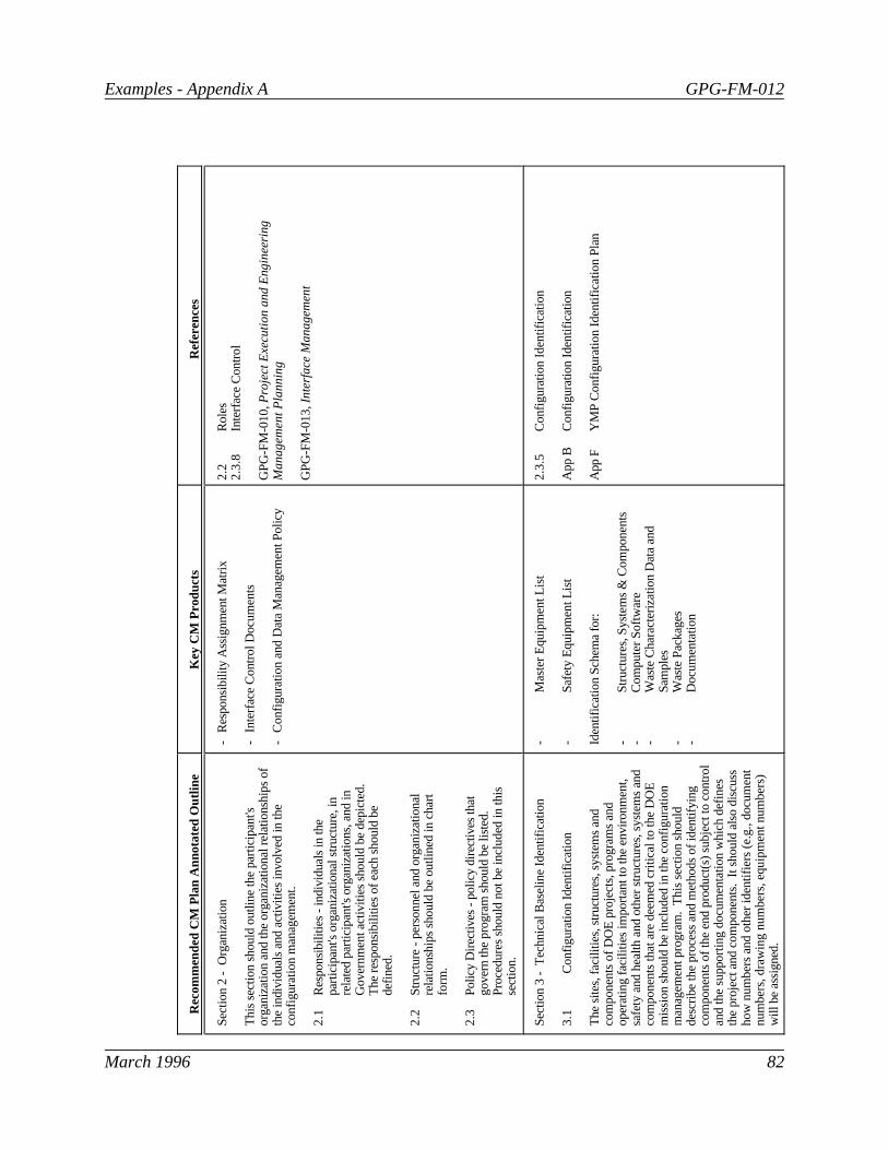
Examples - Appendix A GPG-FM-012
March 1996 82
Rec
omm
ende
d C
M P
lan
Ann
otat
ed O
utlin
eK
ey C
M P
rodu
cts
Ref
eren
ces
Sec
tion
2 -
Org
aniz
atio
n
Thi
s se
ctio
n sh
ould
out
line
the
part
icip
ant's
orga
niza
tion
and
the
orga
niza
tiona
l rel
atio
nshi
ps o
fth
e in
divi
dual
s an
d ac
tiviti
es in
volv
ed in
the
conf
igur
atio
n m
anag
emen
t.
2.1
Res
pons
ibili
ties
- in
divi
dual
s in
the
part
icip
ant's
org
aniz
atio
nal s
truc
ture
, in
rela
ted
part
icip
ant's
org
aniz
atio
ns, a
nd in
Gov
ernm
ent a
ctiv
ities
sho
uld
be d
epic
ted.
The
res
pons
ibili
ties
of e
ach
shou
ld b
ede
fined
.
2.2
Str
uctu
re -
per
sonn
el a
nd o
rgan
izat
iona
lre
latio
nshi
ps s
houl
d be
out
lined
in c
hart
fo
rm.
2.3
Pol
icy
Dire
ctiv
es -
pol
icy
dire
ctiv
es th
atgo
vern
the
prog
ram
sho
uld
be li
sted
.P
roce
dure
s sh
ould
not
be
incl
uded
in th
isse
ctio
n.
-R
espo
nsib
ility
Ass
ignm
ent M
atrix
-In
terf
ace
Con
trol
Doc
umen
ts
-C
onfig
urat
ion
and
Dat
a M
anag
emen
t Pol
icy
2.2
Rol
es2
.3.8
Inte
rfac
e C
ontr
ol
GP
G-F
M-0
10, P
roje
ct E
xecu
tion
an
d E
ng
ine
erin
gM
an
ag
em
en
t P
lan
nin
g
GP
G-F
M-0
13, In
terf
ace
Ma
na
ge
me
nt
Sec
tion
3 -
Tec
hnic
al B
asel
ine
Iden
tific
atio
n
3.1
Con
figur
atio
n Id
entif
icat
ion
The
site
s, fa
cilit
ies,
str
uctu
res,
sys
tem
s an
dco
mpo
nent
s of
DO
E p
roje
cts,
pro
gram
s an
dop
erat
ing
faci
litie
s im
port
ant t
o th
e en
viro
nmen
t,sa
fety
and
hea
lth a
nd o
ther
str
uctu
res,
sys
tem
s an
dco
mpo
nent
s th
at a
re d
eem
ed c
ritic
al to
the
DO
Em
issi
on s
houl
d be
incl
uded
in th
e co
nfig
urat
ion
man
agem
ent p
rogr
am.
Thi
s se
ctio
n sh
ould
desc
ribe
the
proc
ess
and
met
hods
of i
dent
ifyin
gco
mpo
nent
s of
the
end
prod
uct(
s) s
ubje
ct to
con
trol
and
the
supp
ortin
g do
cum
enta
tion
whi
ch d
efin
esth
e pr
ojec
t and
com
pone
nts.
It s
houl
d al
so d
iscu
ssho
w n
umbe
rs a
nd o
ther
iden
tifie
rs (
e.g.
, doc
umen
tnu
mbe
rs, d
raw
ing
num
bers
, equ
ipm
ent n
umbe
rs)
will
be
assi
gned
.
-M
aste
r E
quip
men
t Lis
t
-S
afet
y E
quip
men
t Lis
t
Iden
tific
atio
n S
chem
a fo
r:
-S
truc
ture
s, S
yste
ms
& C
ompo
nent
s-
Com
pute
r S
oftw
are
-W
aste
Cha
ract
eriz
atio
n D
ata
and
Sam
ples
-W
aste
Pac
kage
s-
Doc
umen
tatio
n
2.3
.5C
onfig
urat
ion
Iden
tific
atio
n
App
BC
onfig
urat
ion
Iden
tific
atio
n
App
FY
MP
Con
figur
atio
n Id
entif
icat
ion
Pla
n

Examples - Appendix A GPG-FM-012
March 1996 83
Rec
omm
ende
d C
M P
lan
Ann
otat
ed O
utlin
eK
ey C
M P
rodu
cts
Ref
eren
ces
Sec
tion
3 -
Tec
hnic
al B
asel
ine
Iden
tific
atio
n(C
ontin
ued)
3.2
Tec
hnic
al B
asel
ines
Req
uire
men
ts c
over
ing
prep
arat
ion,
sub
mis
sion
for
DO
E a
ppro
val,
and
subs
eque
nt r
elea
se o
f the
Dep
artm
enta
lly a
ppro
ved
docu
men
tatio
n w
hich
defin
es e
ach
of th
e re
quire
d ba
selin
es s
houl
d be
esta
blis
hed
in th
is s
ectio
n. T
he p
artic
ipan
t's m
etho
dun
der
whi
ch th
e do
cum
enta
tion
shou
ld b
e pr
epar
ed,
appr
oved
by
DO
E, a
nd r
elea
sed,
sho
uld
bede
scrib
ed a
nd th
e tim
e pe
riods
in w
hich
thes
e st
eps
shou
ld b
e ac
com
plis
hed
shou
ld b
e in
dica
ted.
-F
unct
ions
and
Req
uire
men
tsB
asel
ine
-D
esig
n R
equi
rem
ents
Bas
elin
e
-C
onfig
urat
ion
Bas
elin
e
-A
s-B
uilt
Con
figur
atio
n B
asel
ine
2.3
.2T
echn
ical
Bas
elin
e Id
entif
icat
ion
2.3
.3E
stab
lishm
ent o
f Bas
elin
es2
.3.6
Tra
ceab
ility
2.4
.1T
echn
ical
Bas
elin
e fo
r P
roje
cts
2.5
.1T
echn
ical
Bas
elin
e fo
r F
acili
ties
GP
G-F
M-0
09, B
ase
line
Ch
an
ge
Co
ntr
ol
GP
G-F
M-0
10, P
roje
ct E
xecu
tion
an
d E
ng
ine
erin
gM
an
ag
em
en
t P
lan
nin
g
GP
G-F
M-0
16, B
ase
line D
eve
lopm
ent
Sec
tion
4 -
Con
figur
atio
n C
hang
e C
ontr
ol
4.1
Cha
nge
Con
trol
for
Pro
gram
s, P
roje
cts,
and
Ope
ratin
g F
acili
ties
Thi
s se
ctio
n sh
ould
des
crib
e th
e pr
oces
s of
man
agin
g pr
opos
ed c
hang
es to
con
figur
atio
n ite
ms
and
tech
nica
l doc
umen
tatio
n to
ens
ure
prop
osed
chan
ges
are
accu
rate
ly d
escr
ibed
, sys
tem
atic
ally
revi
ewed
and
eva
luat
ed fo
r im
pact
, pro
perly
impl
emen
ted
upon
app
rova
l, an
d pr
oper
ly c
lose
dou
t. T
he c
hang
e co
ntro
l pro
cess
sho
uld
prov
ide
for
tech
nica
l, sc
ope,
cos
t and
sch
edul
e re
view
s w
hich
are
docu
men
ted
as a
cha
nge
pack
age.
Pro
cedu
res
for
cont
rol o
f int
erfa
ces
and
proc
essi
ng r
eque
sts
for
devi
atio
ns o
r w
aive
rs s
houl
d al
so b
e ou
tline
d in
this
sect
ion.
Pro
cess
es a
nd c
ontr
ols
spec
ific
to p
roje
cts
orop
erat
ing
faci
litie
s sh
ould
be
addr
esse
d in
Sec
tion
5or
6, r
espe
ctiv
ely.
Cha
nge
Con
trol
-P
roce
dure
s-
App
rova
l Crit
eria
/Thr
esho
lds
-C
CB
Cha
rter
Inte
rfac
e C
ontr
ol-
Pro
cedu
res
-D
ocum
ents
/Dra
win
gs-
Inte
rfac
e C
ontr
ol W
orki
ngG
roup
Cha
rter
s/P
roce
dure
s
-P
roce
dure
s to
Con
trol
Dev
iatio
ns a
nd W
aive
rs
-P
roce
dure
s to
Con
trol
Was
teIn
vent
ory
Con
figur
atio
n
-W
aste
Inve
ntor
y D
ata
Bas
e
2.3
.4C
hang
e C
ontr
ol2
.3.4
.4P
artic
ipan
t CC
Bs
2.3
.8In
terf
ace
Con
trol
2.3
.12
Con
trol
of D
evia
tions
and
Wai
vers
2.3
.13
Was
te In
vent
ory
Con
figur
atio
n
GP
G-F
M-0
09, B
ase
line
Ch
an
ge
Co
ntr
ol
GP
G-F
M-0
10, P
roje
ct E
xecu
tion
an
d E
ng
ine
erin
gM
an
ag
em
en
t P
lan
nin
g
GP
G-F
M-0
13, In
terf
ace
Ma
na
ge
me
nt
AS
ME
Y14
.24M
, En
gin
ee
rin
g D
raw
ing
Typ
es
AS
ME
Y14
.34M
, Ass
oci
ate
d L
ists
AS
ME
Y14
.25M
, Re
visi
on
s to
En
gin
ee
rin
gD
raw
ing
s

Examples - Appendix A GPG-FM-012
March 1996 84
Rec
omm
ende
d C
M P
lan
Ann
otat
ed O
utlin
eK
ey C
M P
rodu
cts
Ref
eren
ces
Sec
tion
1 -
Intr
oduc
tion
Cov
er S
heet
- s
houl
d pr
ovid
e th
e no
men
clat
ure
ofth
e sy
stem
or
prod
uct,
cont
ract
or, c
ontr
act n
umbe
r,an
d da
te o
f iss
ue.
1.1
Tab
le o
f Con
tent
s
1.2
Spe
cial
Mat
eria
l Fea
ture
s -
the
spec
ial
feat
ures
of t
he p
artic
ipan
t’s fa
cilit
ies,
whi
chha
ve a
det
erm
inin
g ef
fect
on
the
natu
re o
f the
conf
igur
atio
n m
anag
emen
t pro
gram
, sho
uld
be b
riefly
des
crib
ed.
1.3
Spe
cial
Org
aniz
atio
nal F
eatu
res
-ch
arac
teris
tics
such
as
man
ufac
turin
gca
pabi
litie
s, d
esig
n an
d dr
aftin
g pe
rson
nel,
and
orga
niza
tiona
l rel
atio
nshi
ps s
houl
d be
defin
ed.
1.4
Oth
er a
nd/o
r S
peci
al C
onsi
dera
tions
- th
isse
ctio
n sh
ould
add
ress
pec
ulia
ritie
s of
the
conf
igur
atio
n m
anag
emen
t pro
gram
that
resu
lt fr
om p
artic
ipat
ion
by a
larg
e nu
mbe
r of
orga
niza
tions
, use
of m
any
com
mer
cial
item
s,us
e of
exi
stin
gþ d
raw
ings
and
spe
cific
atio
nsor
oth
er d
epar
ture
s fr
om th
e no
rmal
, and
inno
vatio
ns fo
r m
ore
effe
ctiv
e co
nfig
urat
ion
man
agem
ent s
houl
d be
des
crib
ed h
ere.
It
shou
ld a
lso
addr
ess
such
trad
ition
al C
Mas
pect
s as
trai
ning
, CM
res
pons
ibili
ties
and
inte
grat
ions
þ w
ith s
ubco
ntra
ctor
s, s
uppl
iers
,et
c.
Not
e : M
any
of th
e re
fere
nces
list
ed fo
r th
is s
ectio
n,su
ch a
s E
IS/IS
-649
, N
atio
na
l Co
nse
nsu
s S
tan
da
rdfo
r C
on
figu
ratio
n M
an
ag
em
en
t, c
over
all
aspe
cts
of c
onfig
urat
ion
man
agem
ent a
nd c
an b
ere
fere
nced
for
othe
rþ s
ectio
ns o
f the
CM
Pla
n.
Not
e : T
here
are
two
sect
ion
5s in
clud
ed in
this
outli
ne: o
ne fo
r P
roje
cts
and
one
for
Ope
ratin
gF
acili
ties.
Use
the
one
that
is a
ppro
pria
te.
2.1
Pro
cess
Ove
rvie
w2
.3.1
Pla
ns a
nd P
roce
dure
s
10
CF
R 8
30
.12
0, Q
ualit
y A
ssura
nce
DO
E O
430
.1, L
IFE
-CY
CLE
AS
SE
TM
AN
AG
EM
EN
TD
OE
O 5
700.
6C, Q
UA
LIT
Y A
SS
UR
AN
CE
GP
G-F
M-0
01, P
roje
ct M
anagem
ent O
verv
iew
GP
G-F
M-0
02, C
ritic
al D
eci
sion C
riteria
GP
G-F
M-0
10, P
roje
ct E
xecu
tion
an
d E
ng
ine
eri
ng
Ma
na
ge
me
nt
Pla
nn
ing
GP
G-F
M-0
17, Q
ua
lity
Ass
ura
nce
/Qu
alit
y C
on
tro
l
DoD
Dire
ctiv
e 50
10.1
9, Do
D C
on
figu
ratio
nM
an
ag
em
en
t P
rog
ram
EIA
/IS-6
49, N
atio
na
l Co
nse
nsu
s S
tan
da
rd f
or
Co
nfig
ura
tion
Ma
na
ge
me
nt
EIA
/IS-6
32, S
yste
ms
En
gin
ee
rin
g
IEE
E P
12
20
, Sta
nd
ard
fo
r A
pp
lica
tion
an
d M
an
ag
em
en
t o
f th
eS
yste
ms
Engin
eerin
g P
roce
ss
ISO
100
07, Q
ua
lity
Ma
na
ge
me
nt
- G
uid
elin
es
for
Co
nfig
ura
tion
Ma
na
ge
me
nt
MIL
-ST
D-9
73, C
on
figu
ratio
n M
an
ag
em
en
tM
IL-H
DB
K-6
1, C
on
figu
ratio
n M
an
ag
em
en
t H
an
db
oo
k
NIR
MA
PP
-02-
1989
, Po
sitio
n P
ap
er
on
Co
nfig
ura
tion
Ma
na
ge
me
nt

Examples - Appendix A GPG-FM-012
March 1996 85
Rec
omm
ende
d C
M P
lan
Ann
otat
ed O
utlin
eK
ey C
M P
rodu
cts
Ref
eren
ces
Sec
tion
4 -
Con
figur
atio
n C
hang
e C
ontr
ol(C
ontin
ued)
4.2
Com
pute
r S
oftw
are
Cha
nge
Con
trol
Con
trol
s sh
ould
be
esta
blis
hed
for
new
com
pute
rso
ftwar
e an
d m
odifi
catio
ns to
exi
stin
g so
ftwar
e to
ensu
re th
at th
e so
ftwar
e pe
rfor
ms
its d
esig
ned
func
tion.
Thi
s se
ctio
n sh
ould
iden
tify
the
cont
rols
that
will
be
appl
ied
to th
e de
velo
pmen
t and
rev
isio
nof
sof
twar
e us
ed to
per
form
func
tions
nec
essa
ry fo
rfa
cilit
y sa
fety
and
rel
iabi
lity.
-P
roce
dure
s fo
r D
evel
opm
ent
and
Acq
uisi
tion
of S
oftw
are
-S
yste
m R
equi
rem
ents
Spe
cific
atio
n -
Qua
lity
Ass
uran
ce P
lan
-V
erifi
catio
n an
d V
alid
atio
nP
lans
/Rep
orts
-U
sers
Man
ual
-R
ecor
d of
Use
-P
roce
dure
s fo
r C
hang
e C
ontr
olof
Sof
twar
e
-P
roce
dure
s fo
r D
iscr
epan
cyR
epor
ting
and
Err
or N
otifi
catio
n
2.3
.7S
oftw
are
Con
figur
atio
n M
anag
emen
t2
.6C
ompu
ter
Sof
twar
e C
hang
e C
ontr
ol2
.6.1
Sof
twar
e C
hang
e C
ontr
ol2
.6.2
Sof
twar
e C
hang
e P
acka
ges
2.6
.3P
erio
dic
Ver
ifica
tion
2.6
.4R
ecor
ds
App
DS
oftw
are
Con
figur
atio
n M
anag
emen
t
App
FY
MP
Con
figur
atio
n Id
entif
icat
ion
Pla
n
GP
G-F
M-0
10, P
roje
ct E
xecu
tion
an
d E
ng
ine
erin
gM
an
ag
em
en
t P
lan
nin
g
AN
S/IE
EE
Sta
ndar
d 82
8-19
90,
So
ftw
are
Co
nfig
ura
tion
Ma
na
ge
me
nt
Pla
ns
AN
S/IE
EE
Sta
ndar
d 10
42-1
987,
G
uid
e t
o S
oft
wa
reC
on
figu
ratio
n M
an
ag
em
en
t
EIA
Sta
ndar
d IS
/640
, Softw
are
Deve
lopm
ent
ISO
/IEC
122
20, In
form
atio
n T
ech
no
log
y-S
oft
wa
re
ISO
/IEC
122
20-2
, Co
nfig
ura
tion
Ma
na
ge
me
nt
for
So
ftw
are
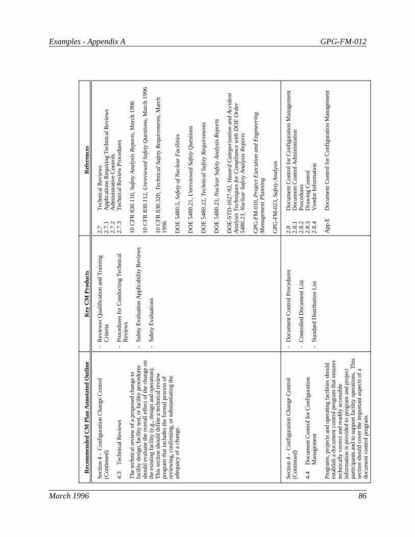
Examples - Appendix A GPG-FM-012
March 1996 86
Rec
omm
ende
d C
M P
lan
Ann
otat
ed O
utlin
eK
ey C
M P
rodu
cts
Ref
eren
ces
Sec
tion
4 -
Con
figur
atio
n C
hang
e C
ontr
ol(C
ontin
ued)
4.3
Tec
hnic
al R
evie
ws
The
tech
nica
l rev
iew
of a
pro
pose
d ch
ange
tofa
cilit
y de
sign
, fac
ility
test
, or
faci
lity
proc
edur
essh
ould
eva
luat
e th
e ov
eral
l effe
ct o
f the
cha
nge
onth
e ex
istin
g fa
cilit
y (e
.g.,
desi
gn a
nd o
pera
tion)
. T
his
sect
ion
shou
ld d
efin
e a
tech
nica
l rev
iew
prog
ram
that
incl
udes
the
form
al p
roce
ss o
fre
view
ing,
con
firm
ing,
or
subs
tant
iatin
g th
ead
equa
cy o
f a c
hang
e.
-R
evie
wer
Qua
lific
atio
n an
d T
rain
ing
Crit
eria
-P
roce
dure
s fo
r C
ondu
ctin
g T
echn
ical
Rev
iew
s
-S
afet
y E
valu
atio
n A
pplic
abili
ty R
evie
ws
-S
afet
y E
valu
atio
ns
2.7
Tec
hnic
al R
evie
ws
2.7
.1A
pplic
atio
ns R
equi
ring
Tec
hnic
al R
evie
ws
2.7
.2A
dmin
istr
ativ
e C
ontr
ols
2.7
.3T
echn
ical
Rev
iew
Pro
cedu
res
10
CF
R 8
30
.11
0, Safe
ty A
naly
sis
Report
s,
Ma
rch
19
96
10
CF
R 8
30
.11
2, Unre
view
ed S
afe
ty Q
uest
ions
, M
arc
h 1
99
6
10
CF
R 8
30
.32
0, Tech
nic
al S
afe
ty R
equirem
ents
, Mar
ch1
99
6
DO
E 5
48
0.5
, Safe
ty o
f Nucl
ear
Faci
litie
s
DO
E 5
48
0.2
1, U
nre
view
ed S
afe
ty Q
uest
ions
DO
E 5
48
0.2
2, T
ech
nic
al S
afe
ty R
equirem
ents
DO
E 5
48
0.2
3, N
ucl
ear
Safe
ty A
naly
sis
Report
s
DO
E-S
TD
-102
7-92
, Ha
zard
Ca
teg
ori
zatio
n a
nd
Acc
ide
nt
An
aly
sis
Te
chn
iqu
es
for
Co
mp
lian
ce w
ith D
OE
Ord
er
54
80
.23
, N
ucl
ea
r S
afe
ty A
na
lysi
s R
ep
ort
s
GP
G-F
M-0
10, P
roje
ct E
xecu
tion
an
d E
ng
ine
erin
gM
an
ag
em
en
t P
lan
nin
g
GP
G-F
M-0
23, S
afe
ty A
naly
sis
Sec
tion
4 -
Con
figur
atio
n C
hang
e C
ontr
ol(C
ontin
ued)
4.4
Doc
umen
t Con
trol
for
Con
figur
atio
nM
anag
emen
t
Pro
gram
s, p
roje
cts
and
oper
atin
g fa
cilit
ies
shou
ldes
tabl
ish
a do
cum
ent c
ontr
ol p
rogr
am th
at e
nsur
este
chni
cally
cor
rect
and
rea
dily
acc
essi
ble
info
rmat
ion
is p
rovi
ded
to p
rogr
am a
nd p
roje
ctpa
rtic
ipan
ts a
nd to
sup
port
faci
lity
oper
atio
ns.
Thi
sse
ctio
n sh
ould
cov
er th
e im
port
ant a
spec
ts o
f ado
cum
ent c
ontr
ol p
rogr
am.
-D
ocum
ent C
ontr
ol P
roce
dure
s
-C
ontr
olle
d D
ocum
ent L
ist
-S
tand
ard
Dis
trib
utio
n Li
st
2.8
Doc
umen
t Con
trol
for
Con
figur
atio
n M
anag
emen
t2
.8.1
Doc
umen
t Con
trol
Adm
inis
trat
ion
2.8
.2P
roce
dure
s2
.8.3
Dra
win
g C
ontr
ol2
.8.4
Ven
dor
Info
rmat
ion
App
ED
ocum
ent C
ontr
ol fo
r C
onfig
urat
ion
Man
agem
ent

Examples - Appendix A GPG-FM-012
March 1996 87
Rec
omm
ende
d C
M P
lan
Ann
otat
ed O
utlin
eK
ey C
M P
rodu
cts
Ref
eren
ces
Sec
tion
5 -
Con
figur
atio
n C
hang
e C
ontr
ol fo
rP
roje
cts
Thi
s se
ctio
n sh
ould
des
crib
e th
e pr
oces
s th
aten
sure
s ch
ange
s to
the
conf
igur
atio
n of
the
end
prod
uct(
s) a
nd th
eir
com
pone
nts
and
chan
ges
topr
ojec
t tec
hnic
al b
asel
ines
are
rev
iew
ed, a
utho
rized
,pr
oper
ly e
xecu
ted
and
verif
ied
to b
e co
mpl
ete
and
clos
ed o
ut.
-C
hang
e C
ontr
ol P
roce
dure
s
-S
tand
ardi
zed
Cha
nge
Pro
posa
lF
orm
s
-C
hang
e R
evie
ws
and
Impa
ctE
valu
atio
ns
-A
udita
ble
and
Tra
ceab
le C
hang
eD
ocum
enta
tion
2.4
.2C
hang
e C
ontr
ol fo
r P
roje
cts
2.4
.2.1
Cha
nge
Initi
atio
n an
d S
ubm
ittal
2.4
.2.2
Cha
nge
Rev
iew
and
Impa
ct E
valu
atio
n2
.4.2
.3C
hang
e D
ispo
sitio
n2
.4.2
.4D
irect
ed C
hang
es2
.4.2
.5C
hang
e Im
plem
enta
tion
2.4
.2.6
Tra
inin
g2
.4.2
.7C
hang
e C
lose
out
2.4
.2.8
Cha
nge
Tra
ckin
g
Sec
tion
5 -
Con
figur
atio
n C
hang
e C
ontr
ol fo
rO
pera
ting
Fac
ilitie
s
For
ope
ratin
g fa
cilit
ies,
a c
onfig
urat
ion
chan
ge is
any
mod
ifica
tion
to th
e te
chni
cal b
asel
ines
, the
faci
lity'
s co
nfig
urat
ion
or th
e op
erat
ing
proc
edur
esan
d lim
its.
Thi
s se
ctio
n sh
ould
des
crib
e th
eco
nfig
urat
ion
chan
ge c
ontr
ol p
roce
ss w
hich
ens
ures
all p
ropo
sed
chan
ges
are
revi
ewed
aga
inst
bas
elin
edo
cum
enta
tion
and
all a
ffect
ed e
lem
ents
of t
hete
chni
cal b
asel
ine
are
upda
ted
as n
eede
d.
Add
ition
ally
, thi
s se
ctio
n sh
ould
des
crib
e pr
oces
ses
for: (1
) m
odifi
catio
n co
ntro
l
(2)
tem
pora
ry m
odifi
catio
n co
ntro
l, an
d
(3)
setp
oint
con
trol
.
-W
ork
Con
trol
Pro
cedu
res
-C
hang
e C
ontr
ol P
roce
dure
s
-S
tand
ardi
zed
Cha
nge
Pro
posa
lF
orm
s
-C
hang
e R
evie
ws
and
Impa
ctE
valu
atio
ns
-A
udita
ble
and
Tra
ceab
le C
hang
eD
ocum
enta
tion
2.5
.2O
pera
ting
Fac
ility
CC
Bs
2.5
.3W
ork
Con
trol
2.5
.4
Cha
nge
Con
trol
for
Ope
ratin
g F
acili
ties
2.5
.4.1
Cha
nge
Initi
atio
n an
d S
ubm
ittal
2.5
.4.2
Cha
nge
Rev
iew
and
Impa
ct E
valu
atio
n2
.5.4
.3C
hang
e D
ispo
sitio
n2
.5.4
.4D
irect
ed C
hang
es2
.5.4
.5C
hang
e Im
plem
enta
tion
2.5
.4.6
Tra
inin
g2
.5.4
.7C
hang
e C
lose
out
2.5
.4.8
Cha
nge
Tra
ckin
g
10
CF
R 8
30
.31
0, Co
nd
uct
of
Op
era
tion
s a
t D
OE
Nu
cle
ar
Fac
ilitie
s, M
arc
h 1
99
6
10
CF
R 8
30
.34
0, M
ain
ten
an
ce M
an
ag
em
en
t,
Ma
rch
19
96
DO
E O
430
.1, L
IFE
-CY
CLE
AS
SE
T M
AN
AG
EM
EN
T
DO
E 4
330.
4A, C
ON
DU
CT
OF
MA
INT
EN
AN
CE
AT
DO
EF
AC
ILIT
IES
DO
E 5
480.
19, C
ON
DU
CT
OF
OP
ER
AT
ION
S A
T D
OE
FA
CIL
ITIE
S
DO
E-S
TD
-107
3-93
, Gu
ide
fo
r O
pe
ratio
na
l Co
nfig
ura
tion
Ma
na
ge
me
nt
Pro
gra
m
INP
O 8
5-03
1, Re
qu
ire
me
nts
fo
r th
e C
on
du
ct o
f T
ech
nic
al
Su
pp
ort
at
Nu
cle
ar
Po
we
r S
tatio
ns

Examples - Appendix A GPG-FM-012
March 1996 88
Rec
omm
ende
d C
M P
lan
Ann
otat
ed O
utlin
eK
ey C
M P
rodu
cts
Ref
eren
ces
Sec
tion
5 -
Con
figur
atio
n C
hang
e C
ontr
ol fo
rO
pera
ting
Fac
ilitie
s (C
ontin
ued)
5.1
Mod
ifica
tion
Con
trol
A m
odifi
catio
n is
any
pla
nned
cha
nge
in th
e de
sign
of a
faci
lity
stru
ctur
e, s
yste
m, o
r co
mpo
nent
. M
odifi
catio
ns m
ay r
esul
t fro
m a
n ap
prov
ed c
hang
epr
opos
al o
r be
dire
cted
by
man
agem
ent.
Thi
sse
ctio
n sh
ould
add
ress
adm
inis
trat
ive
cont
rols
that
ensu
re m
odifi
catio
ns to
faci
lity
SS
Cs
are
prop
erly
desi
gned
, rev
iew
ed, a
ppro
ved,
inst
alle
d, te
sted
, and
docu
men
ted.
-P
roce
dure
s fo
r M
odifi
catio
nC
ontr
ol
-D
esig
n D
ocum
enta
tion
-In
stal
latio
n D
ocum
enta
tion
-R
evis
ed S
afet
y A
naly
sis
-R
evis
ed O
SR
/TS
R L
imits
-R
evis
ed O
pera
ting
& M
aint
enan
ceP
roce
dure
s, D
ocum
enta
tion,
and
Tra
inin
g M
ater
ials
-R
evis
ed V
endo
r M
anua
ls
2.5
.5M
odifi
catio
n C
ontr
ol2
.5.5
.1R
eque
sts
for
Fac
ility
Mod
ifica
tions
2.5
.5.2
Des
ign
2.5
.5.3
Inst
alla
tion
2.5
.5.4
Doc
umen
tatio
n2
.5.5
.5T
rain
ing
2.5
.5.6
Qua
lity
Ver
ifica
tion
2.5
.5.7
Mat
eria
ls P
rocu
rem
ent
2.5
.5.8
Sch
edul
e
10
CF
R 8
30
.31
0, Co
nd
uct
of
Op
era
tion
s a
t D
OE
Nu
cle
ar
Fac
ilitie
s, M
arc
h 1
99
6
10
CF
R 8
30
.34
0, M
ain
ten
an
ce M
an
ag
em
en
t,
Ma
rch
19
96
DO
E 4
330.
4A, C
ON
DU
CT
OF
MA
INT
EN
AN
CE
AT
DO
EF
AC
ILIT
IES
DO
E 5
480.
19, C
ON
DU
CT
OF
OP
ER
AT
ION
S A
T D
OE
FA
CIL
ITIE
S
DO
E-S
TD
-107
3-93
, Gu
ide
fo
r O
pe
ratio
na
l Co
nfig
ura
tion
Ma
na
ge
me
nt
Pro
gra
m
INP
O 8
5-03
1, Re
qu
ire
me
nts
fo
r th
e C
on
du
ct o
f T
ech
nic
al
Su
pp
ort
at
Nu
cle
ar
Po
we
r S
tatio
ns

Examples - Appendix A GPG-FM-012
March 1996 89
Rec
omm
ende
d C
M P
lan
Ann
otat
ed O
utlin
eK
ey C
M P
rodu
cts
Ref
eren
ces
Sec
tion
5 -
Con
figur
atio
n C
hang
e C
ontr
ol fo
rO
pera
ting
Fac
ilitie
s (C
ontin
ued)
5.2
Tem
pora
ry M
odifi
catio
n C
ontr
ol fo
rO
pera
ting
Fac
ilitie
s
Tem
pora
ry m
odifi
catio
ns a
re u
sual
ly m
inor
alte
ratio
ns to
faci
lity
com
pone
nts,
equ
ipm
ent,
orsy
stem
s w
ith r
espe
ct to
app
rove
d dr
awin
gs o
r ot
her
desi
gn d
ocum
ents
. T
his
sect
ion
shou
ld d
escr
ibe
the
adm
inis
trat
ive
cont
rol s
yste
ms
for
inst
alla
tion
ofte
mpo
rary
mod
ifica
tions
and
sho
uld
incl
ude
proc
esse
s th
at e
nsur
e te
mpo
rary
mod
ifica
tions
to in
-se
rvic
e fa
cilit
y co
mpo
nent
s, e
quip
men
t, an
dsy
stem
s ar
e pr
oper
ly e
valu
ated
, aut
horiz
ed, a
ndco
ntro
lled
usin
g m
etho
ds s
imila
r to
thos
e fo
rpe
rman
ent m
odifi
catio
ns.
-P
roce
dure
s fo
r T
empo
rary
Mod
ifica
tion
Con
trol
-T
empo
rary
Mod
ifica
tion
Doc
umen
tatio
n
-T
empo
rary
Mod
ifica
tion
Con
trol
Log
-S
hift
Tra
inin
g on
Tem
pora
ryM
odifi
catio
ns
-A
nnot
ated
Dra
win
gs, P
roce
dure
s
-T
empo
rary
Mod
ifica
tion
Tag
ging
-T
empo
rary
Mod
ifica
tion
Aud
its
-V
erifi
catio
n of
Tem
pora
ryM
odifi
catio
n R
emov
al
2.5
.6T
empo
rary
Mod
ifica
tion
Con
trol
2.5
.6.1
Tec
hnic
al R
evie
w2
.5.6
.2A
utho
rizat
ion
2.5
.6.3
Inst
alla
tion
2.5
.6.4
Doc
umen
tatio
n2
.5.6
.5R
evie
ws
of In
stal
led
Tem
pora
ry M
odifi
catio
ns
10
CF
R 8
30
.31
0, Co
nd
uct
of
Op
era
tion
s a
t D
OE
Nu
cle
ar
Fac
ilitie
s, M
arc
h 1
99
6
DO
E 5
480.
19, C
ON
DU
CT
OF
OP
ER
AT
ION
S A
T D
OE
FA
CIL
ITIE
S
DO
E-S
TD
-107
3-93
, Gu
ide
fo
r O
pe
ratio
na
l Co
nfig
ura
tion
Ma
na
ge
me
nt
Pro
gra
m
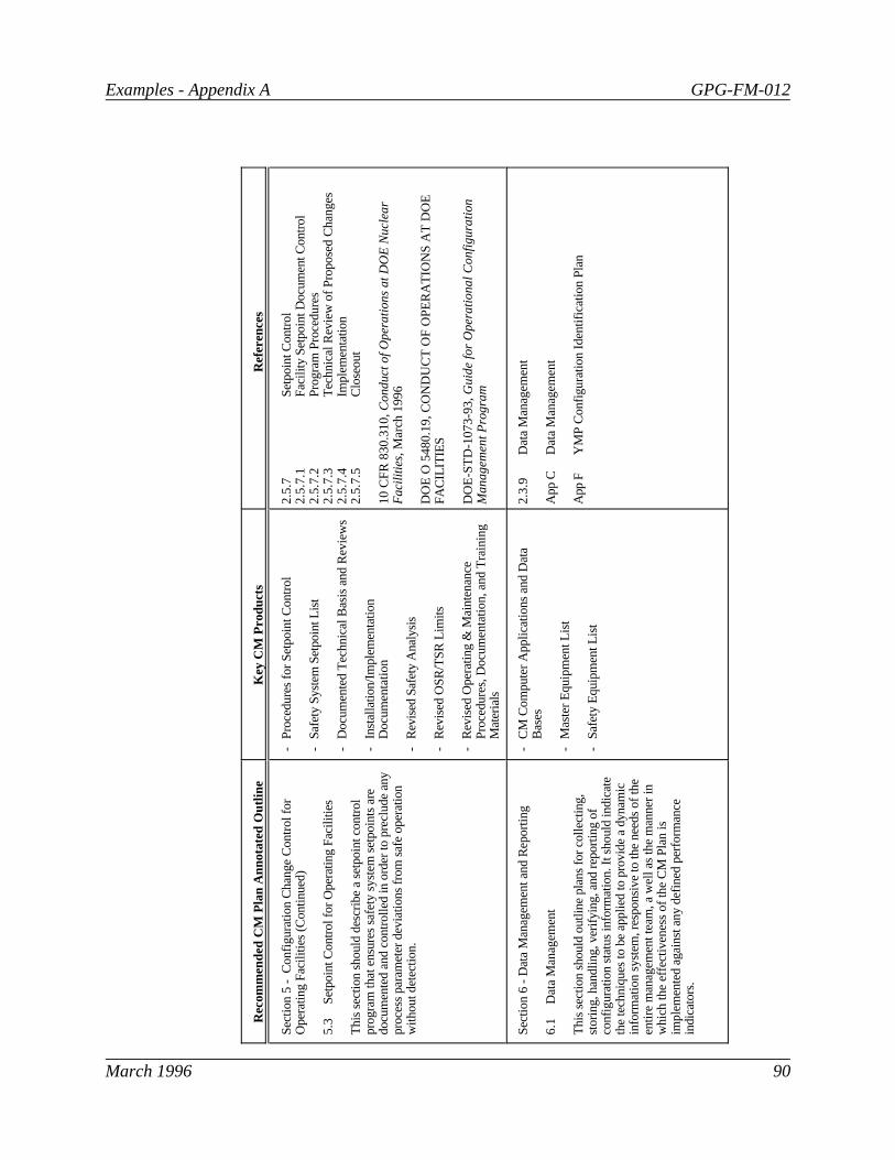
Examples - Appendix A GPG-FM-012
March 1996 90
Rec
omm
ende
d C
M P
lan
Ann
otat
ed O
utlin
eK
ey C
M P
rodu
cts
Ref
eren
ces
Sec
tion
5 -
Con
figur
atio
n C
hang
e C
ontr
ol fo
rO
pera
ting
Fac
ilitie
s (C
ontin
ued)
5.3
Set
poin
t Con
trol
for
Ope
ratin
g F
acili
ties
Thi
s se
ctio
n sh
ould
des
crib
e a
setp
oint
con
trol
prog
ram
that
ens
ures
saf
ety
syst
em s
etpo
ints
are
docu
men
ted
and
cont
rolle
d in
ord
er to
pre
clud
e an
ypr
oces
s pa
ram
eter
dev
iatio
ns fr
om s
afe
oper
atio
nw
ithou
t det
ectio
n.
-P
roce
dure
s fo
r S
etpo
int C
ontr
ol
-S
afet
y S
yste
m S
etpo
int L
ist
-D
ocum
ente
d T
echn
ical
Bas
is a
nd R
evie
ws
-In
stal
latio
n/Im
plem
enta
tion
Doc
umen
tatio
n
-R
evis
ed S
afet
y A
naly
sis
-R
evis
ed O
SR
/TS
R L
imits
-R
evis
ed O
pera
ting
& M
aint
enan
ceP
roce
dure
s, D
ocum
enta
tion,
and
Tra
inin
gM
ater
ials
2.5
.7S
etpo
int C
ontr
ol2
.5.7
.1F
acili
ty S
etpo
int D
ocum
ent C
ontr
ol2
.5.7
.2P
rogr
am P
roce
dure
s2
.5.7
.3T
echn
ical
Rev
iew
of P
ropo
sed
Cha
nges
2.5
.7.4
Impl
emen
tatio
n2
.5.7
.5C
lose
out
10
CF
R 8
30
.31
0, Co
nd
uct
of
Op
era
tion
s a
t D
OE
Nu
cle
ar
Fac
ilitie
s, M
arc
h 1
99
6
DO
E O
548
0.19
, CO
ND
UC
T O
F O
PE
RA
TIO
NS
AT
DO
EF
AC
ILIT
IES
DO
E-S
TD
-107
3-93
, Gu
ide
fo
r O
pe
ratio
na
l Co
nfig
ura
tion
Ma
na
ge
me
nt
Pro
gra
m
Sec
tion
6 -
Dat
a M
anag
emen
t and
Rep
ortin
g
6.1
Dat
a M
anag
emen
t
Thi
s se
ctio
n sh
ould
out
line
plan
s fo
r co
llect
ing,
stor
ing,
han
dlin
g, v
erify
ing,
and
rep
ortin
g of
conf
igur
atio
n st
atus
info
rmat
ion.
It s
houl
d in
dica
teth
e te
chni
ques
to b
e ap
plie
d to
pro
vide
a d
ynam
icin
form
atio
n sy
stem
, res
pons
ive
to th
e ne
eds
of th
een
tire
man
agem
ent t
eam
, a w
ell a
s th
e m
anne
r in
whi
ch th
e ef
fect
iven
ess
of th
e C
M P
lan
isim
plem
ente
d ag
ains
t any
def
ined
per
form
ance
indi
cato
rs.
-C
M C
ompu
ter
App
licat
ions
and
Dat
aB
ases
-M
aste
r E
quip
men
t Lis
t
-S
afet
y E
quip
men
t Lis
t
2.3
.9D
ata
Man
agem
ent
App
CD
ata
Man
agem
ent
App
FY
MP
Con
figur
atio
n Id
entif
icat
ion
Pla
n

Examples - Appendix A GPG-FM-012
March 1996 91
Rec
omm
ende
d C
M P
lan
Ann
otat
ed O
utlin
eK
ey C
M P
rodu
cts
Ref
eren
ces
Sec
tion
6 -
Dat
a M
anag
emen
t and
Rep
ortin
g(C
ontin
ued)
6.2
Rep
ortin
g
Thi
s se
ctio
n sh
ould
des
crib
e re
port
s th
at w
ill b
epr
ovid
ed o
n va
rious
attr
ibut
es o
f the
end
pro
duct
conf
igur
atio
n an
d th
e pe
rfor
man
ce o
f the
conf
igur
atio
n m
anag
emen
t sys
tem
.
Rep
orts
on:
-E
nd P
rodu
ct C
onfig
urat
ion
Sta
tus
-C
onfig
urat
ion
Doc
umen
tatio
n-
Cur
rent
/His
toric
Bas
elin
es-
Cha
nge
Req
uest
s-
Cha
nge
Pro
posa
ls-
Cha
nge
Not
ices
-V
aria
nces
-W
arra
nty
Dat
a/H
isto
ry-
Rep
lace
men
ts b
y M
aint
enan
ce A
ctio
n-
Con
figur
atio
n V
erifi
catio
n an
d A
udit
Sta
tus/
Act
ion
Item
Clo
seou
t
2.3
.10
Rep
ortin
g
GP
G-F
M-0
06, P
erf
orm
an
ce A
na
lysi
s a
nd
Re
po
rtin
g
GP
G-F
M-0
09, B
ase
line
Ch
an
ge
Co
ntr
ol
GP
G-F
M-0
10, P
roje
ct E
xecu
tion
an
d E
ng
ine
erin
gM
an
ag
em
en
t P
lan
nin
g
GP
G-F
M-0
15, P
roje
ct R
evie
ws
GP
G-F
M-0
29, S
yste
ms
Analy
sis
and A
ssess
ment
Sec
tion
7 -
Rev
iew
s
Thi
s se
ctio
n sh
ould
add
ress
ass
essm
ents
per
form
edto
mea
sure
the
effe
ctiv
enes
s of
the
conf
igur
atio
nm
anag
emen
t pro
cess
, and
con
sist
ency
bet
wee
n th
epr
ojec
t phy
sica
l sys
tem
and
the
docu
men
tatio
n th
atre
pres
ents
that
sys
tem
.
- P
rogr
amm
atic
Ass
essm
ents
-P
hysi
cal C
onfig
urat
ion
Ass
essm
ents
2.3
.11
Rev
iew
s2
.3.1
1.1
Pro
gram
mat
ic A
sses
smen
t2
.3.1
1.2
Phy
sica
l Con
figur
atio
n A
sses
smen
ts
GP
G-F
M-0
05, T
est
an
d E
valu
atio
n
GP
G-F
M-0
10, P
roje
ct E
xecu
tion
an
d E
ng
ine
erin
gM
an
ag
em
en
t P
lan
nin
g
GP
G-F
M-0
15, P
roje
ct R
evie
ws
GP
G-F
M-0
29, S
yste
ms
Analy
sis
and A
ssess
ment

Examples - Appendix A GPG-FM-012
March 1996 92
APPENDIX BCONFIGURATION IDENTIFICATION
1. GENERAL
The sites, facilities, structures, systems and components important to the environment,safety, and health and other SSCs that are deemed critical to the mission should beincluded in the configuration management program. Unique identifiers should be used inall phases of programs, projects, and operating facilities to ensure documentation can beassembled for the sites, facilities, SSCs as required. The example provided in Appendix Fof this Guide illustrates how the information included in this appendix can be applied.
2. GUIDELINES
2.1 Identification of Physical Items
The process for configuration identification of physical items includes:
• The criteria and scope for the physical items to be included in configurationmanagement to be defined.
• Facilities and structures to be uniquely identified.
• The identification of systems, system boundaries, and system interfaces to beclearly delineated and the systems uniquely identified.
• Major components of systems to be uniquely identified by a function code.
• The unique identifier consist of the system, function code, and address to uniquelyidentify the component and location within a system.
• The location (address) of components within the system to be assigned and shownon drawings.
• Labels to be attached to the physical items showing the unique identifier.
• Documentation generated throughout the life of programs and projects referencethe unique identifiers.
2.2 Identification of Structures and Systems
Examples - Appendix B GPG-FM-012
March 1996 93
The boundaries and interfaces for each structure and system should be clearly describedand documented. These bounded structures and systems should be uniquely identified. The unique identifiers assigned to the structures and systems should be used throughoutthe life of the project or operating facility for identification of the structures and systems.
2.3 Identification of Components
Components within systems should be uniquely identified as follows:
• A controlled list of function codes should be developed and maintained current ateach project or operating facility.
• Each component requiring unique identification should be assigned a function codefrom the controlled list of function codes depending on the primary function thecomponent performs. (For example, a valve might have a controlled function codeof VLV from the controlled function code list.)
• The component should be assigned an arbitrary numeric address depicting therelative position of the component in the system to other components. Thisrelative location assignment for the component is called the "address" of thecomponent.
• The unique identifier for a component should consist of the system identifier, thecomponent function code and the component address.
• The unique identifier should be depicted on design drawings.
• The components should have a label affixed to show the unique identifier whenpossible. Labeling should comply with the requirements of DOE 5480.19, ChapterXVIII, Equipment and Piping Labeling.
Guidelines for determining the level to which individual components should be uniquelyidentified are given in Table B-1.

Examples - Appendix B GPG-FM-012
March 1996 94
Table B-1. Level of Unique Identification of Components.
The level to which components are uniquely identified can be determined using thefollowing guidelines:
A. The component is at a level of assembly to allow ready access to decisioninformation.
B. The component is at a level at which change incorporation and configurationverification is required and documented.
C. The component provides the basis for preparation of operating and maintenancemanuals.
D. The component requires visibility and control because of its high cost, criticality inthe system, or contractual/acceptance significance.
E. The component does not contain a subassembly requiring independent changeincorporation and configuration verification.
2.4 Identification of Additional Components and Subcomponents
Design changes may result in the requirement for additional components to be added to asystem. These components should be assigned the appropriate function code and thecorrect address relative to other components and should be included on design drawingsand be labeled. When desirable or required to identify subcomponents of a component,the function code for the subcomponent should be selected depending on the function ofthe subcomponent and the address should be the same as the component.
2.5 Identification of Assembled Packaged Equipment or Skid-Mounted Equipment
If the components would have required identification in an engineered system, thecomponents of an assembled packaged equipment or skid-mounted equipment should havethe components uniquely identified. These unique identifiers should be shown ondrawings and should be labeled.
2.6 Identification of Software
Software configuration items are those computer codes that directly control processesimportant to operations or specify design output or are used to refine design input for a

Examples - Appendix B GPG-FM-012
March 1996 95
configuration item. Examples are provided in Section 2.3.7 of this Guide. Softwaresubject to the configuration management program should be uniquely identified as aconfiguration item. Unique identification of software requires:
• General description and primary purpose.
• Version, release number, and level.
• Unique identifiers for each program; traceable from source listings/object modulesto the codes output.
• Version and revision number and date, traceable from source listings/objectmodule to the codes output.
• Cross reference to unique configuration item(s), if applicable.
• Cross references to the codes supporting documentation, including requirementsand design specifications and user/operations manuals at the same version/revisionlevel, as applicable.
2.7 Identification of Waste Characterization Data and Samples
Waste characterization data to be used as design or process input should be included in theconfiguration management program. Waste characterization requires full sampletraceability and accountability. The waste characterization data and samples should beuniquely identified. This requires:
• Use of separate, unique identifiers for multiple, discrete samples.
• Identification of the individual items or portions resulting from subdivision that arereadily traceable to the original sample.
• Traceability of samples to applicable documentation and documentation toapplicable samples by the unique identifier.
• Traceability of samples to their origin including site location and orientation.
• Use of labels (bar codes) or other methods of identification to show the uniqueidentifier during processing.

Examples - Appendix B GPG-FM-012
March 1996 96
• Maintenance of controlled site location maps for identifying sample locations.
2.8 Identification of Waste Packages
All waste packages should be included in the configuration management program. Wastepackages should be uniquely identified to ensure accountability and traceability as follows:
• A unique identifier should be assigned to each waste package.
• Labels or other methods of identification of the unique identifier should beprovided for each package and applied in a manner not to compromise the integrityof the waste package.
• The unique identifier should be legible at least to the end of the period ofretrievability.
• Waste package documentation should be retrievable by the unique identifier.
2.9 Identification of Documentation
Documentation associated with configuration items should be included in theconfiguration management program to ensure traceability of requirements andretrievability of information. Documentation associated with configuration items shouldbe uniquely identified to ensure traceability and retrievability as follows:
• A standard numbering system for the generic baseline document types such asdrawings, procedures, calculations, etc., should be established and usedthroughout the life of the program, project or operating facility.
• The standard numbering system should provide for unique identification and cross-referencing of all mutually dependent documents.
• The standard numbering system should be procedurally controlled.
• The unique document identifier along with the revision level and effective dateshould be clearly identified on each issue of a document.
• Documents supplied by vendors should either conform with the requirednumbering system, or have a numbering system that is judged sufficient, usedconsistently by the vendor, and provides for retrievability of documentation.

Examples - Appendix C GPG-FM-012
March 1996 97
APPENDIX CDATA MANAGEMENT
1. GENERAL
Computerized information systems should be used as tools to monitor configurationmanagement technical baseline information and changes thereto. The configurationmanagement related data bases should include an index of all configuration items anddocuments representing technical baseline information, an index of all proposed andapproved changes to the technical baseline, and the status of the changes thereto. Whenused, these information systems becomes extremely important to the permitting, licensingand operations of projects and operating facilities. Configuration management computerapplications along with the technical data base and the records management computerapplications contain a substantial portion of the information necessary to substantiate fullregulatory compliance.
The integration of these data bases and the controlled and rigorous data managementtechniques used in the design of the computer applications supporting configurationmanagement should meet the requirements of the approved configuration managementprogram. Section 4 of the example provided in Appendix F of this Guide illustrates howto the information included in this appendix can be applied.
2. DEFINITIONS
Computer Hardware, Software, and Resources. The equipment, computer programs,and information systems professionals that collectively make up the information resourcemanagement function to be utilized for development of systems that enhance themanagement and control functions of programs, projects and operating facilities in orderto meet the goals and objectives of the Mission.
Sponsor. The organization with direct contact to the information resource managementorganization that (1) identifies requirements for a specific computer software application;(2) supports development, implementation, and utilization of the specific computerapplication; (3) budgets resources and supports procurement of information resourcesrelated to the computer software application; (4) sets priorities and long range directionfor the computer software application; and (5) develops service-level requirements as theyrelate to the computer software application.
User Group. A formal group established to review, approve and provide priorities fordevelopment and maintenance of information systems supporting configuration
Examples - Appendix C GPG-FM-012
March 1996 98
management with members from affected and interested organizations to include, but notlimited to, information systems.
3. ROLES
3.1 Program Office
The Program Office directors should:
• Provide requirements for computer hardware, software, and information resourcemanagement resources as they relate to the configuration management program.
• Support design, development, implementation, and utilization of computerhardware, software, and resources for the configuration management program.
• Recommend changes to other related procedures as those procedures impact thecomputer hardware, software, and resources that relate to the management andcontrol of configuration management baselines and changes thereto.
• Act as sponsor for configuration management computer applications at theProgram Office level.
• Establish and chair an Program Office configuration management computerapplications user group.
• Provide long-range plans for information systems as they relate to configurationmanagement systems.
• Ensure that proper records are developed documenting all approved changes toinformation systems.
3.2 Field Elements
Field Elements should:
• Establish configuration management software applications and support activitiesthat meet the intent of this procedure.

Examples - Appendix C GPG-FM-012
March 1996 99
• Provide short- and long-range configuration management computer hardware,software, and resource requirements to the appropriate Field Element organizationresponsible for information systems.
• Identify all configuration management computer applications used in theorganization with identification of the software scope, sponsoring organization,input requirements, and output provided. This information is utilized to enhancethe integration of computer software and help to reduce the proliferation ofdisconnected and inefficient computer applications.
• Review and approving specifications for configuration management computerapplications.
• Identify training requirements for their organizations as they relate to configurationmanagement software applications.
4. GUIDELINES
4.1 Development of Configuration Management Applications
In addition to the guidelines established in Appendix B of this Guide, the followingguidelines apply to the development of configuration management applications.
• Joint development with affected and implementing organizations of configurationmanagement software applications should be required in order that the goals andobjectives of the configuration management program are effectively and efficientlymet.
• Purchased software and hardware components should be utilized whenever feasibleand practical.
• Extensive use of prototyping should be provided by the software developer toensure requirements are met effectively and efficiently prior to final delivery of adetailed design.
• Service levels should be developed for on-line response times, batch reportturnaround, error resolution, minor changes, and other service levels as consideredimportant to the operation and use of the configuration management applications.

Examples - Appendix C GPG-FM-012
March 1996 100
• Development of appropriate documentation, including a user manual, should be required prior to implementation and acceptance of developed or acquiredapplications.
• An operational user group should be established to review, approve, and prioritizeenhancements to the software application once implemented.
4.2 Operations and Maintenance of the Configuration Management Systems
Maintenance of configuration management software applications should be treatedcommensurate with the original development techniques. Authorization for minor changesthat include only output format changes or correction of minor software errors should beat the discretion of the information services organization; however, all normaldocumentation, testing, and training should continue to be required. All major changesand corrections should be reviewed by the user group for approval and priority. Operational requirements for configuration management software applications includedata verification techniques, reporting requirements, and data discrepancy reporting.
In addition to the guidelines provided in section 2.3.9, section 2.6, and Appendix D; thefollowing guidelines apply to operation and maintenance of configuration managementsoftware applications.
• Data entered into the configuration management computer applications should beindependently verified. Data errors should be reported when detected.
• Project personnel should be provided tools to design, develop, and generate themaximum amount of reporting possible, minimizing the impact to informationservices personnel.
4.3 Configuration Management Systems Integration
The successful implementation of the configuration management program depends heavilyon the ability to retrieve information using many different data attributes as keyinformation. The traceability of information is of paramount importance in baselinecontrol and ensuring that technical information is up to date and accurate. Configurationmanagement actively supports the elimination of uncontrolled and redundant data, and theintegration of data when feasible and cost effective. The following guidelines relate to theintegration of configuration management information.
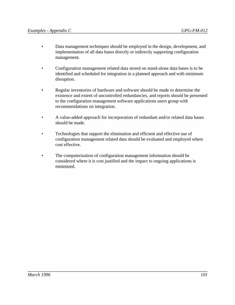
Examples - Appendix C GPG-FM-012
March 1996 101
• Data management techniques should be employed in the design, development, andimplementation of all data bases directly or indirectly supporting configurationmanagement.
• Configuration management related data stored on stand-alone data bases is to beidentified and scheduled for integration in a planned approach and with minimumdisruption.
• Regular inventories of hardware and software should be made to determine theexistence and extent of uncontrolled redundancies, and reports should be presentedto the configuration management software applications users group withrecommendations on integration.
• A value-added approach for incorporation of redundant and/or related data basesshould be made.
• Technologies that support the elimination and efficient and effective use ofconfiguration management related data should be evaluated and employed wherecost effective.
• The computerization of configuration management information should beconsidered where it is cost justified and the impact to ongoing applications isminimized.

Examples - Appendix C GPG-FM-012
March 1996 102
This page intentionally left blank.

Examples - Appendix D GPG-FM-012
March 1996 103
APPENDIX DSOFTWARE CONFIGURATION MANAGEMENT
1. GENERAL
The configuration management program should ensure that essential and criticalcomputer software is identified and controlled. Software designated to be controlledthrough the configuration control process should be uniquely identified and established aspart of the technical baseline. Criteria for inclusion of software in the configurationmanagement program is provided in sections 2.3.7 and 2.6 of this Guide.
2. ROLES
2.1 Program and Field Element Secretariat Organizations
Program Office and Field Element Secretariat organizations should be responsible forproviding an index of all software configuration items (SCIs), including changes and thestatus for use.
2.2 Field Elements
Field Elements should be responsible for:
• Establishing and maintaining procedures to control SCIs within their organizations.
• Utilizing an index for SCIs with appropriate cross-references to relatedinformation, including proposed and approved changes with status information.
• Developing a systems requirements specification for all SCIs either existing,acquired, or to be developed.
• Controlling the SCI codes and documentation throughout the software life-cycle toinclude controlled distribution of appropriate documentation.
• Retesting SCIs when related/involved software and hardware (operating systems,run-time routines, interpreters, microcode, input devices and others as appropriate)changes are made that have potential impact on the output of the SCI.
• Establishing a discrepancy reporting and corrective action system.

Examples - Appendix D GPG-FM-012
March 1996 104
• Establishing independent reviews and approvals for developed or acquiredsoftware at major points in the development or operations life cycles per qualityassurance guidelines for independent reviews.
• Maintaining a log of all uses of SCIs to ensure traceability in the event of errordetection.
3. GUIDELINES
3.1 Development and Acquisition of Software Configuration Items
The following guidelines apply to the development and acquisition of softwareconfiguration items:
• Prior to development or acquisition of an SCI, a systems requirementsspecification should be developed identifying the basis for source codedevelopment, functional requirements, data interface requirements, hardwarerequirements, mathematical models, assumptions for use and any other pertinentinformation appropriate to the pre-design phase.
• In conjunction with the development of the systems requirements specification, asoftware quality assurance plan should be developed. The software qualityassurance plan should identify all quality assurance measures and techniques to beused in qualifying the software for use, to include software development projectorganization structure, design methodology, coding standards and conventions,configuration control measures, automated tools to be used for development andtesting (if applicable), hardware considerations, independent review techniques,training for project team leads and programming personnel, securityconsiderations, and other information appropriate to the development of softwarequality assurance.
• The system requirements specification should be independently reviewed andapproved prior to CCB submission. When the independent review is completed,the system requirements specification should be submitted to the appropriate CCBfor approval. For in-house development no additional phases of work should becompleted until the CCB has approved the system requirements specification.
• The source code should be independently reviewed and approved when completed. This review should be documented program by program.

Examples - Appendix D GPG-FM-012
March 1996 105
• A software verification and validation plan should be created in conjunction withthe detailed design phase. The software verification and validation plan shouldaddress all controls to ensure that the requirements are captured in the design andthat the design meets all criteria.
• The software should be independently tested to determine that it meets the originalrequirements and design specifications (verification).
• The software should be independently reviewed to determine that the output iscorrectly computed and produces results consistently (validation) under varyingassumptions to be used once the software is placed into production.
• The results of the verification and validation phases should be formallydocumented in the software verification and validation report. The test datashould be saved and used in order to requalify the code in the event of changes tothe source code and related software and hardware.
• Organizations inputting data into the system should be responsible for the accuracyand completeness of the data. Error messages and warnings generated by the codeshould be thoroughly researched prior to using the results.
• Development of appropriate documentation, including a users manual, should berequired prior to implementation and acceptance of developed or acquiredsoftware.
• Contractors performing configuration management software development workshould be formally assessed as to relevant experience and qualifications.
• A record of the use of all output should be maintained in the event that errors arediscovered at some later point in time. A notification mechanism should beestablished to report the consequences of errors and their potential impact on usesof the software output.
3.2 Operations and Maintenance of Software Configuration Items - Change Control
Maintenance of SCIs should be treated commensurate with original development. Authorization for minor changes that include only output format changes or correction ofminor software errors should be at the discretion of the software sponsor; however, allnormal documentation, testing and training should continue to be required. All major

Examples - Appendix D GPG-FM-012
March 1996 106
changes and corrections should be reviewed by the CCB for approval. The followingguidelines apply to operation and maintenance of software configuration items:
• All proposed changes to SCIs should be documented and presented to theappropriate CCB.
• The proposed change should be identified in the appropriate data managementsystem per Appendix C of this Guide.
• Upon change approval the data management system should be updated to reflectthe new status. Likewise, should the change be unapproved or held, the datamanagement system should be updated to reflect this change in status.
• Changes should be evaluated to determine the acceptability of using results fromprevious revisions of the software. Where it is determined that the resultsproduced by previous revisions of the software may result in an unacceptableoutput, all users of the previous revision should be notified of the changes andacknowledge that the results obtained from prior revisions do or do not materiallyaffect their work.
• The change should be developed, tested, and implemented in accordance withapproved procedures.
• Upon implementation of the change, all appropriate documentation should beupdated. This documentation includes as a minimum the Users Manual and theupdated systems requirements specification.
• The output generated by the software should identify the current version andrevision of the software and the effective date of the revision.
• Training should be conducted and training records maintained to attest to suchtraining, where appropriate.
3.3 Discrepancy Reporting and Error Notification
Traceability of use of design input or output is critical to safety. Discrepancy reportingprovides a necessary feedback loop in the process to ensure that all errors are reported,users are notified of the situation, and as a result are able to adjust to the correctinformation. The following guidelines are related to discrepancy reporting and errornotification.

Examples - Appendix D GPG-FM-012
March 1996 107
• All uses of SCIs should be documented with the date and time of the use and theversion of the SCI in effect at the time.
• Should an error in the SCI or related software be discovered, immediatenotification is required using the standard methods of discrepancy reporting.
• Once the magnitude of the error is known, all previous users of the softwareshould be notified in writing and requested to determine the impact of the error ontheir previous use of the software.
• Corrections to the software and root cause analysis should be immediatelyundertaken.

Examples - Appendix D GPG-FM-012
March 1996 108
This page intentionally left blank.

Examples - Appendix E GPG-FM-012
March 1996 109
APPENDIX EDOCUMENT CONTROL FOR CONFIGURATION MANAGEMENT
1. GENERAL
Documents should be controlled and distributed to ensure that only the applicableapproved version is available for use and to ensure prompt communication of changes. Asdiscussed in Section 2.8, the effective control of documents is essential to the success ofthe configuration management program because the documents are the vehicles used tocommunicate information to affected organizations. The configuration managementprogram should ensure processes are in place such that:
• Controlled documents are uniquely identified and identification systems areproceduralized.
• Controlled documents are reviewed, approved, changed, and released throughchange control processes.
• Controlled documents are kept current by controlled distribution, including areceipt acknowledgment process.
• Users needing controlled copies have ready access to current revisions ofcontrolled copies.
• Data bases providing revision level information are controlled and maintainedcurrent.
• Record retrieval systems are in place that allow timely retrieval of historicaldocuments and the cross-referenced material in those documents.
• Effective dates are established for controlled documents that allow for changes toimpacted documents and related training.
All technical baseline documents should be issued as controlled documents. On approval,these documents should be entered in the appropriate controlled document list.
2. DEFINITIONS
Controlled Copy. A document that is maintained on a current basis by means of arevision control process and a formal transmittal/receipt acknowledgment system.

Examples - Appendix E GPG-FM-012
March 1996 110
Controlled Document. A document that is prepared, reviewed, revised, and approved inaccordance with established procedures, has controlled distribution, and is maintained on acurrent basis.
Controlled Documents List. A list of the documents to be controlled. This list includesinformation such as document number, title, revision number and date, effective date, andoriginating and distributing organization.
Distributing Organization . That organization responsible for reproduction, distribution,and transmittal receipt/acknowledge of controlled documents.
Document. Any written or pictorial information describing, defining, specifying,reporting, or certifying activities, requirements, procedures, or results.
Originating Organization . That organization responsible for preparing, revising,reviewing, approving, completing, or statusing a document and releasing it to theappropriate organization for distribution.
Standard Distribution List . A list for each controlled document identifying therecipient's position, location, and controlled copy number.
3. ROLES
3.1 Program Office and Field Elements
The Program Office and Field Element directors and/or managers should:
• Approve the Standard Distribution List for the controlled documents within theirareas of responsibility.
• Generate and distribute a Controlled Document List.
• Ensure only current revisions of controlled documents are used in performingquality-related work activities.
3.2 Document Originating Organizations
Controlled document originating organizations should:

Examples - Appendix E GPG-FM-012
March 1996 111
• Ensure controlled documents released for distribution have been appropriatelyreviewed for technical adequacy and approval.
• Ensure effective dates for controlled documents are established prior to release fordistribution.
3.3 Document Distributing Organizations
Controlled document distributing organizations should be responsible for ensuringcontrolled documents are distributed in accordance with approved procedures.
4. GUIDELINES
4.1 Document Generation
Organizations that generate documents, which are under the scope of this appendix,procedurally should define the process for the preparation, format, review, approval,revision, and verification of the technical adequacy of those documents.
4.2 Document Identification
4.2.1 Document Numbering
• Each controlled document should be identified by a unique number that appears onall pages of the document. The original identification number should be retainedthroughout all changes to and revisions of the document. Should a document becanceled, that unique number should not be reused.
• The current revision number of each controlled document should appear on allchanged pages issued since initial issuance of or last complete revision.
• Pages within a controlled document should be numbered in a manner that allowspage accountability.
4.2.2 Control Identification
Controlled documents should be clearly identified as controlled by use of colored paper ora color-identified stamp indicating a "controlled" status. Black should not be anacceptable color identification for the control stamp. Without this control identification,documents should be considered uncontrolled.
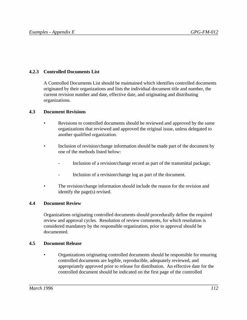
Examples - Appendix E GPG-FM-012
March 1996 112
4.2.3 Controlled Documents List
A Controlled Documents List should be maintained which identifies controlled documentsoriginated by their organizations and lists the individual document title and number, thecurrent revision number and date, effective date, and originating and distributingorganizations.
4.3 Document Revisions
• Revisions to controlled documents should be reviewed and approved by the sameorganizations that reviewed and approved the original issue, unless delegated toanother qualified organization.
• Inclusion of revision/change information should be made part of the document byone of the methods listed below:
- Inclusion of a revision/change record as part of the transmittal package;
- Inclusion of a revision/change log as part of the document.
• The revision/change information should include the reason for the revision andidentify the page(s) revised.
4.4 Document Review
Organizations originating controlled documents should procedurally define the requiredreview and approval cycles. Resolution of review comments, for which resolution isconsidered mandatory by the responsible organization, prior to approval should bedocumented.
4.5 Document Release
• Organizations originating controlled documents should be responsible for ensuringcontrolled documents are legible, reproducible, adequately reviewed, andappropriately approved prior to release for distribution. An effective date for thecontrolled document should be indicated on the first page of the controlled

Examples - Appendix E GPG-FM-012
March 1996 113
document, allowing sufficient time for the development/revision of implementingprocedures and training as appropriate.
• When the revised document is maintained in a manual, an updated table of contentsor an index should be prepared which accompanies the revision that is forwardedto the distributing organization.
4.6 Document Distribution
• A unique controlled copy number should be assigned to each controlled documentlisted on the Standard Distribution List.
• A systematic transmittal and receipt acknowledgment process should be used tocontrol distribution and track receipt of controlled documents. Individuallyaddressed transmittals should be used to transmit controlled copies of documentsto each person on the Standard Distribution List. The transmittal record shouldalso contain any necessary instructions, including the deadline for return of thesigned transmittal receipt and disposition instructions for supersededdocuments/pages.
• The recipient of each controlled copy should sign and return the transmittal to thedistributing organization by the due date specified and maintain his/her controlledcopy current.
4.7 Standard Distribution List
Standard distribution lists should be developed for controlled documents, and maintainedby the organization distributing controlled documents. Additions to or deletions from thestandard distribution lists should be authorized by the organization originating thedocuments. Controlled distribution should be limited to avoid the creation of an undulycumbersome or unmanageable document control system that may ultimately be self-defeating.
4.8 Document Use
It is the responsibility of the user to ensure that only the current revision of controlleddocuments are used in the conduct of activities. Currency should be readily verifiable bycontacting the distributing organization or reference to the Controlled Document List.

Examples - Appendix E GPG-FM-012
March 1996 114
4.9 Document Assessment
At least annually, each distributing organization should require each controlled copyholder to inventory and verify currency of all controlled copies assigned to the particularposition. Random assessments of controlled copies should be made by the distributingorganizations to confirm the adequacy of the controlled distribution process on an as-needed basis.
4.10 Maintenance of Controlled Copies
4.10.1 Master Copy
A master copy is the copy used by distributing organizations for reproduction,distribution, and reference of the current revision. The master copy should not be checkedout of the distributing organization's files and access control should be maintained. Onlythe current revision should be considered a master copy. Historical, superseded, orobsolete revisions should be maintained in the appropriate records systems.
4.10.2 Controlled Copies
Recipients of each controlled copy should maintain that controlled copy current, promptlyinform the distributing organization of any changes in physical relocation, positionresponsibilities, or titles, and at least annually assess the accuracy of their controlledcopy(ies).

Examples - Appendix F GPG-FM-012
March 1996 115
APPENDIX FYMP CONFIGURATION IDENTIFICATION PLAN
DRAFTPLAN FOR IMPLEMENTATION OF
YUCCA MOUNTAIN SITE CHARACTERIZATIONPROJECT CONFIGURATION IDENTIFICATION
REVISION 0
TABLE OF CONTENTS

Examples - Appendix F GPG-FM-012
March 1996 116
INTRODUCTION
Configuration management for the Yucca Mountain Site Characterization Project (YMP)supports management of the Project Baseline by providing the mechanisms to identify,document, and control the functional and physical characteristics of the YMP’s products. It is an integrated approach to the technical, cost and schedule, quality assurance, andadministrative actions necessary to manage the YMP. Configuration management focuseson four principal activities: configuration identification, configuration control,configuration status accounting, and configuration review. The requirements for each ofthese principal activities are set forth in the YMP Configuration Management Plan (CMP).
To date, the focus of the CMP and the YMP has been on establishing and institutionalizingcontrols for site characterization activities and development of the documents whichestablish the technical, cost, and schedule baselines for the Mined Geologic DisposalSystem (MGDS). Technical and Management Support Services (T&MSS) has recognizedthat current configuration management program requirements, which have been adequatefor these early stages of the MGDS, should be further refined to incorporate morerigorous management controls and enhanced information systems that will be needed tosupport later stages of the MGDS life cycle. Configuration identification andconfiguration status accounting are two areas where T&MSS has performed analysis anddeveloped the necessary refinements which are recommended for the Management andOperations (M&O) contractor to implement.
The purpose of this plan is twofold. First, it describes the recommended changes. Thechanges are presented in four interrelated sections:
1. Project Baseline Control
2. Configuration Item and Activity Selection
3. Configuration Item and Activity Identifiers
4. Configuration Information System
Except for the section on Project Baseline Control, each recommended change ispresented in a format that includes:
1. Current Situation
2. Background Information
3. Proposed Action

Examples - Appendix F GPG-FM-012
March 1996 117
The section on Project Baseline Control provides essential information that is common tothe other sections.
This Plan addresses “what” needs to be changed and “why.” It does not address “how”the recommended changes should be implemented. Implementation of the recommendedchanges will require interface with other YMP organizations and Participants. It isprobable that exact details of the recommended changes will be modified as a result ofsuch interfaces.
A detailed implementation plan and schedule should be developed which address “how”the recommendations should be implemented. Implementation should consider currentand future changes in management areas addressed by this plan. As of this writing,T&MSS is aware of proposed changes to YMP criteria for: (1) determining theimportance of activities or items and (2) identifying documents and records. Additionally,this plan itself recommends changes to the WBS. These ongoing or proposed changesmay require details of recommendations made by this plan to be modified. However, thebasic recommendations will remain valid.
The second purpose of this plan is to bring T&MSS activities funded by the YMP to anorderly close for the configuration management subtasks of Configuration Identificationand Configuration Information System Development. This information should proveuseful in developing further implementation of configuration management principles andpractices by the M&O contractor.
1. PROJECT BASELINE CONTROL
U.S. Department of Energy (DOE) Order DOE 4700.1 requires management of theProject Baseline which is composed of the YMP technical, cost, and schedule baselines. Configuration management is one of a number of disciplines that is applied to managementof the YMP technical baseline. It also interfaces with YMP Planning and Control System(PACS) to integrate cost and schedule impacts of approved changes to the technicalbaseline.
Configuration management provides the management controls and tools to ensure that theproduct acquired satisfies the technical and operational requirements of the YMP technicalbaseline. It utilizes the same management controls and tools to ensure that the technicalrequirements are clearly defined and controlled throughout the product’s life cycle.
For the YMP, there are three product types controlled by the configuration managementprogram. These product types are defined collectively as “configuration items (CIs)” and

Examples - Appendix F GPG-FM-012
March 1996 118
include: the geographical features of the Yucca Mountain site; project activities related tocharacterization of the site and development of MGDS technical requirements; and thephysical structures, systems, components, and software of the Mined Geologic DisposalSystem (MGDS). Major elements of the MGDS life cycle are: site characterization,engineered subsystems design, system performance assessment, licensing, and MGDSconstruction, operation, and closure.
The CMP recognizes that requirements will be added and modified, and increased detailwill be needed as MGDS development proceeds through its life cycle. In the early stagesof the life cycle, the items controlled by configuration management are the documents thatdefine: site features, site characterization activities, and the MGDS technical baseline. Activities controlled are those related to developing the technical baseline: sitecharacterization, engineered subsystems design, system performance assessment, andlicensing.
As development proceeds into later stages of the MGDS life cycle, items controlled byconfiguration management will expand to include the actual software as well as thedetailed technical baseline documentation defining those physical structures, system,components, and software. Activities controlled will be those related to MGDSconstruction, operation, and closure including maintenance and modification of MGDSstructures, systems, components, and software.
To date, the focus of the CMP and the YMP has been on the early stages of the MGDSlife cycle. It is recognized that current requirements, which have been adequate for theearly stages of the MGDS, should be further refined to incorporate more rigorousmanagement controls and enhanced information systems that will be needed to supportlater stages of the MGDS life cycle. Configuration identification and configuration statusaccounting are two areas where analysis has been performed and recommendationdeveloped for the necessary refinements.
Configuration identification is the foundation of a configuration management program. Itincludes both the selection of CIs to be governed by the configuration managementprogram and the selection of the documentation which describes the functional andphysical characteristics of the CIs. This documentation includes both technical baselinedocumentation and non-baseline documentation.
The technical baseline documentation establishes the design bases for the MGDS anddescribes the functional and physical characteristics of the CIs. Non-baselinedocumentation is comprised of operating and maintenance procedures, vendor manuals,

Examples - Appendix F GPG-FM-012
March 1996 119
inspection procedures, and other documents that use the technical design baselinedocumentation as input criteria.
Currently, configuration status accounting for the YMP utilizes both manual andcomputerized information system to cross-reference and track CIs and their associatedbaseline and non-baseline documentation. The computerized Configuration InformationSystem (CIS) also records and reports on the implementation of changes to the CIs andtheir baseline documentation and triggers corresponding review and change of non-baseline documentation, if required.
Existing YMP requirements for configuration identification and configuration statusaccounting should be further refined to:
1. Provide more rigorous criteria for selection of items and activities to be placed underconfiguration control.
2. Establish a configuration item numbering convention that will support later stages ofthe YMP’s life cycle.
3. Provide for a Configuration Information System (CIS) that is capable of supportingYMP requirements throughout its life cycle.
2. CONFIGURATION ITEM AND ACTIVITY SELECTION
2.1 Current Situation
As indicated in the previous section and in the CMP, configuration identificationestablishes the requirements for selection and identification of site features, sitecharacterization activities, and MGDS items (structures, system, components, andsoftware) that are placed under configuration control. It also integrates the YMP cost andschedule baseline impacts of approved changes to the technical baseline.
While the CMP identifies top-level CIs, it does not provide sufficient criteria for definingand selecting lower level items and activities to be placed under configuration control.
2.2 Background Information
As discussed in the previous section, there are three product types controlled by theconfiguration management program. These products are defined collectively as CIs andinclude: site features, site characterization activities, and MGDS items. These CIs are

Examples - Appendix F GPG-FM-012
March 1996 120
divided into two categories: those related to site characterization and those related toMGDS physical subsystems. Criteria for determining which features, activities, and itemswill be placed under configuration management are not clearly defined. However, thereare existing YMP criteria which can be applied.
Key documents which establish the YMP criteria for determining the importance of afeature, activity, or item are 10 CFR 60, NUREG-1318, and AP-6.17Q. AP-6.17Qdescribes the method and responsibilities for identifying:
1. Items important to public radiological safety and waste isolation.
2. Activities that could affect a natural barrier’s ability to isolate waste.
3. Items determined to be not important to safety, waste isolation, and associatedactivities.
Controlled lists are in place which document the results of the determination process. However, these lists which are the primary indicators of the importance of items to theYMP, are not subject to a disciplined change management system such as the CCBmechanism. The controlled lists are identified and described as follow:
1. Q-List-identifies Items Important to Safety (IITS) and Items Important to WasteIsolation (IITWI). The Q-list has two sections and one appendix.
2. Quality Activities List (QAL) - identifies activities that could affect a natural barriersability to isolate waste.
3. Project Requirements List (PR List) - identifies items and activities that wereevaluated for inclusion in the Q-List or the QAL and determined not to be: importantto safety, important to waste isolation, or quality activities. It also identifies activitiesexempted from the Q-List for QAL evaluation process. The PR List has two sectionsand one appendix.
Exempt items or activities are those whose function or purpose have been determined,by simple logic, to be unrelated to public radiologic health and safety or wasteisolation. These include:
a. Activities whose purpose is to demonstrate feasibility of equipment, tools, ortechniques; do not use technology considered to be beyond state of the art; and donot involve disturbance or characterization of natural elements of phenomena.

Examples - Appendix F GPG-FM-012
March 1996 121
b. Activities that support general administration of the project such as budgetexercises, action item tracking, accounting, general office services, etc.
c. Items such as office trailers, temporary office facilities, etc.
In summary, the Q-List, QAL and PR List classify items and activities as important tosafety, important to waste isolation, and as quality activities. This classification scheme issummarized in Table 1.
Table 1 Classification Scheme.
LIST CLASSIFICATION IDENTIFIERS1 2
Q-List IITS WBS and MGDS-SR
Q-List IITWI (Engineered) WBS and MGDS-SR
Q-List IITWI (Natural) WBS and SCPB Table
QAL Quality Activity WBS and SCPB
PR List not IITS or IITWI to be determined
PR List not Quality Activity WBS, SCPB, and PCA
PR List Exempt WBS, SCPB, and MGDS-SR
An item can be both IITS and IITWI (Engineered).1
Identifiers are those used internal to the referenced list.2
2.3 Proposed Action
The M&O contractor should revise the CMP to provide more rigorous criteria forselecting features, activities, and items to be placed under configuration control. Selectionof CIs should be based on the classification discussed above and the following gradedapproach:
1. Q-List and QAL features, activities, and items should be selected as CIs, baselined,and subject to all requirements of the CMP.

Examples - Appendix F GPG-FM-012
March 1996 122
2. PR List features, activities, and items, other than Exempt, should also be selected asCIs, baselined, and subject to the CMP requirements necessary to ensure control of thecost and schedule baselines.
3. Exempt features, activities, and items should not be selected as CIs and should not besubject to requirements of the CMP. However, they should be subject to PACS costand schedule controls as determined by the cost and schedule management disciplines.
The approach presented above allows baseline management to focus on the items andactivities important to safety, waste isolation, and quality. As the MGDS develops, thequantity of items and activities controlled and the complexity of baseline management willincrease dramatically. The ability to distinguish and focus management attention on itemsimportant to the MGDS will be essential to success of the YMP.
3.0 CONFIGURATION ITEM AND ACTIVITY IDENTIFIERS
3.1 Current Situation
As discussed under Project Baseline Control and described in the CMP, configurationidentification establishes the requirements for selection and identification of CIs that areplaced under configuration control.
While the CMP establishes a CI numbering convention that supports current YMPrequirements, it does not establish a CI numbering convention that will totally supportYMP requirements through later stages of the YMP’s life cycle.
Additionally, YMP contract and other management control mechanisms may not provideadequate controls on YMP Participants to ensure consistent and efficient implementationof the YMP’s configuration identification methodology.
3.2 Background Information
Background information for this section is provided in six subsections. The first fivesubsections focus on CI numbering. The focus of the final subsection is on managementcontrol of YMP Participants.
The first subsection addresses configuration identification principles while the secondsubsection identifies the multiple methods of identification currently being used on theproject. The third subsection addresses management control of the WBS and the fourthsubsection describes a proposed CI numbering convention which integrates the multiple

Examples - Appendix F GPG-FM-012
March 1996 123
methods currently being used. The fifth subsection recommends configurationidentification responsibilities for implementation of the proposed CI numberingconvention.
3.2.1 Configuration Identification Principles
Identification of a CI with its corresponding baseline and non-baseline documentation isaccomplished through the use of unique identifiers for both the CI and for itsdocumentation.
Documentation may describe more than one CI and therefore identifiers are requiredwithin a document to specify which CI is being described and to cross-reference CIs anddocuments with other CIs and documents.
Likewise, a CI may be composed of a number of subcomponents, parts, or subactivitiesthat, in turn, may have documents uniquely applicable to them, therefore requiring thesubcomponent, part, or subactivity to have its own unique identifier.
The YMP’s configuration identification numbering scheme must be able to recognize theserelationships and the relationships show in Figure 1.
3.2.2 Multiple Methods of Identification
Currently, there are five methods by which the YMP identifies site features, activities anditems, and documentation thereof:
1. The YMP WBS Dictionary.
2. The numbering convention used in the Site Characterization Program Baseline(SCPB).
3. The major system acquisition cost account identification code assigned by the YMPMGDS-Systems Requirements (MGDS-SR) document.
4. The configuration item numbering convention established in Section 3 of the CMP.
5. The convention used to identify documents and records as specified in the RecordsManagement Plan (RMP).

Examples - Appendix F GPG-FM-012
March 1996 124
For configuration management to successfully integrate the technical, cost and schedule,quality assurance, and administrative activities necessary to manage the Project Baseline, aCI numbering convention must be established that will integrate all five of the abovemethods. A brief description of these five methods of identifying site features, activities,items, and documentation is provided in the following paragraphs.
The YMP WBS Dictionary identifies and defines individual YMP work elements as thebasis for assignment of tasks, budgeting, schedule planning, integrating key YMPfunctions, measuring and monitoring technical, cost, and schedule progress, and thereporting of progress. Each YMP work element is assigned a numerical identifier that hasa hierarchical relationship to other YMP work elements.
The SCPB defines the program to provide data used to determine the suitability of a sitefor the MGDS, to support MGDS licensing, and to support design of the MGDS. Itestablishes a numbering convention based on an issues hierarchy approach to resolvequestions about the performance of the MGDS. The numbering convention reflects thethree-tiered framework consisting of key issues, issues, and information needs.
The MGDS-SR is a system level technical baseline document that identifies MGDSrequirements and functions, defines MGDS subsystem physical boundaries, and describesphysical and functional interfaces between subsystems. Section III of the MGDS-SRprovides a listing and definition of each physical subsystem that comprises the MGDS. Each Subsystem is assigned a uniform major system acquisition cost account identificationcode that will be used in all design documents that deal with MGDS physical subsystems.
The CMP establishes the YMP’s approach to and requirements for configurationidentification. Section 3 of the CMP establishes a configuration item and activity identifierbased on the third-level elements of the YMP WBS Dictionary in combination with a four-digit number that is unique to each item or activity. The CMP also establishes anumbering convention for the documents that identify, describe, or define theconfiguration characteristics of the item or activity. This descriptor document number isbased on the configuration item number and a four digit serial number that is unique foreach document.
The RMP establishes a numbering convention for documents and records. Theconvention is based on the WBS number corresponding to the activity that generated thedocument or record and an alpha code to identify the type of document or record.
3.2.3 Management Control of the WBS

Examples - Appendix F GPG-FM-012
March 1996 125
DOE 4700.1, Part II.B.3 states that, “Following design and the development of aspecification tree, the WBS shall be revised to reflect the end product. Throughoutsystems engineering, the WBS shall be updated to reflect current status of the endproduct.” This requirement is also discussed in the DOE WBS Guide, DOE/MA-0295,IV.B.2, which states, “The framework for designating the configuration items on a projectis the WBS, which needs to be extended sufficiently to clearly define all element subject toconfiguration management.”
As the SCPB, the MGDS-SR, and subordinate design requirements documents aredeveloped, the WBS should be revised to reflect revised site characterization activities andmore detailed identification of the MGDS physical structures, systems, and subsystems. The YMP does not currently implement this approach to managing the WBS.
If this approach is adopted by the YMP, the WBS would integrate the multiple methods ofidentification and the numbering convention proposed in this plan could be furthersimplified.
3.2.4 Proposed Numbering Convention
As discussed previously, CI is a collective term that includes site features, sitecharacterization activities, and MGDS items. For assignment of configuration identifiers,these CIs are divided into two categories: those related to site characterization and thoserelated to MGDS physical subsystems.
Site features and activities significant to development of data for site characterization andsystems requirements will be placed under configuration management and have a uniqueconfiguration identifier.
Likewise, items comprising the physical structures, systems, components, and software ofthe MGDS will be placed under configuration management and be assigned a uniquecomponent identifier.
A configuration item and activity numbering convention that will integrate all of the abovehas been proposed as shown in Figure 2.
The proposed identifier has three major segments. The first segment establishes a tie tothe YMP WBS Dictionary and is followed by an alpha designator that indicates whetherthe third segment is related to site characterization or to a systems requirement. If thethird segment is to identify a site characterization feature or activity, then it will be as

Examples - Appendix F GPG-FM-012
March 1996 127
shown in Figure 3. If the third segment is to identify a systems requirement physicalsubsystem component, it will be as shown in Figure 4.
A more comprehensive explanation of the proposed configuration item and activitynumbering convention is provided in Attachment 1 of this plan.
3.2.5 Proposed Configuration Identification Responsibilities
The responsibilities for developing, assigning, and utilizing site characterizationconfiguration identifiers would be as follow:
1. Project Control Branch (PCB) develops the WBS and extends it sufficiently to clearlydefine all elements subject to configuration management based on the design baseline(i.e., SCPB, MGDS-SR, ESF-DR).
2. The Regulatory and Site Evaluation Division (RSED) develops the SCPB to define thesite characterization investigations, studies, and activities needed to resolve design andperformance issues.
3. The YMP Assessment Team identifies items and activities to be placed on the Q-List,QAL and PR List.
4. The M&O contractor determines the site features and activities that will be placedunder configuration management based on the Q-List, QAL and PR List (seeProposed Action discussed under Configuration Item and Activity Selection).
5. The M&O contractor assigns identifiers at the activity level, based on the WBS andSCPB.
6. The responsible YMP Participant assigns alphanumeric descriptors to features oractivities below the activity level of the SCPB.
7. YMP Participants utilize these configuration identifiers and cross-reference to theseidentifiers throughout the life of the YMP.
8. The responsible YMP Participant prepares data sheets or enters the unique identifierinto the CIS along with other descriptive and cross-reference information, such asname of the feature or title of the activity, and documentation that describes thefeature or activity.

FIGURE 1TYPICAL CONFIGURATION ITEM AND
DOCUMENTATION RELATIONSHIPS
ENGINEERING DOCUMENTS
BASELINE DOCUMENTS
CONFIGURATION ITEMS
CHARACTERIZATION STUDIES & ACTIVITIES
NON-BASELINE DOCUMENTS
NOTE: Engineering Documents consist of the drawings and specifications required to define, procure, fabricate, construct, install, and test the specific piece of equipment defined as a configuration item.
EXAMPLE: A proposed change to an engineering document could impact a baseline document requiring revision of the baseline document before the engineering document could be changed. The change to the engineering document could also impact: other engineering documents; the physical configuration of the CI; and non-baseline documents, such as operating procedures.
p:\files\hill\graphics\ymp-1.prs

Examples - Appendix F GPG-FM-012
March 1996 129
Responsibilities for developing, assigning, and utilizing MGDS subsystem componentconfiguration identifiers would be as follow:
1. The WBS, Q-List, QAL, and PR List are developed and maintained as describedabove.
2. In the MGDS-SR and subordinate design requirements documents, the Engineeringand Development Division (EDD) defines the physical subsystems and establishes theuniform major system acquisition cost account identification codes which will be usedin all design documents that deal with the physical subsystems.
3. The M&O contractor defines the function codes to be used for components and sub-components consistent with those recommended by the Institute of Electrical andElectronic Engineers (IEEE) but customized to meet the needs of the YMP.
4. EDD assigns identifiers based on the WBS, MGDS-SR and subordinate designrequirements documents, Configuration Management defined function codes, andEDD assigned unique “addresses.”
5. EDD captures the configuration identifier for the component on the drawings.
6. YMP Participants use these component identifiers and cross-reference to theseidentifiers throughout the life of the YMP.
7. EDD or the responsible YMP Participant prepare data sheets or enter the uniquecomponent identifier into the CIS along with other descriptive and cross-referenceinformation, such as name of the component, next higher assembly, documentationthat describes the component, and part numbers.
3.2.6 Management Control of YMP Participants
DOE 4700.1, Part III.C.3 states that non-DOE organizations participating in the project,“...Be required for their portion of the work to prepare and maintain a configurationmanagement plan that integrates with the project level plan.” The Order further statesthat, “The plan should include discussion of how configuration management will beconducted on the project and what items will be so managed.”
The intent of DOE 4700.1 is to contractually require YMP Participants to developconfiguration management programs that are integrated with the YMP CMP. The YMPOhas yet to fund this for Participants and so this is not currently being done for the YMP.
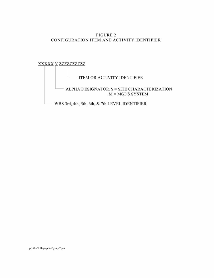
FIGURE 2CONFIGURATION ITEM AND ACTIVITY IDENTIFIER
XXXXX Y ZZZZZZZZZZ
ITEM OR ACTIVITY IDENTIFIER
ALPHA DESIGNATOR, S = SITE CHARACTERIZATION M = MGDS SYSTEM
WBS 3rd, 4th, 5th, 6th, & 7th LEVEL IDENTIFIER
p:\files\hill\graphics\ymp-2.prs

FIGURE 3SITE CHARACTERIZATION CONFIGURATION IDENTIFIER
XXXXX S ZZ ZZZZZZZZ
ITEM OR ACTIVITY IDENTIFIER
ALPHA DESIGNATOR, S = SITE CHARACTERIZATION M = MGDS SYSTEM
WBS 3rd, 4th, 5th, 6th, & 7th LEVEL IDENTIFIER
CHARACTERIZATION FEATURE OR ACTIVITY DESCRIPTOR
FIGURE 4MGDS SUBSYSTEM COMPONENT CONFIGURATION IDENTIFIER
XXXXX M ZZZ ZZZZZZZ
MGDS-SR SUBSYSTEM CODE
ALPHA DESIGNATOR, S = SITE CHARACTERIZATION M = MGDS SYSTEM
WBS 3rd, 4th, 5th, 6th, & 7th LEVEL IDENTIFIER
UNIQUE COMPONENT CODE AND ADDRESS IDENTIFIER
p:\files\graphics\ymp-3&4.prs

Examples - Appendix F GPG-FM-012
March 1996 132
The changes proposed to resolve the issues impacting the integrity of configurationidentification and to enhance control of the Project Baseline require consistentimplementation on the part of YMP Participants. Without appropriate contractualagreement commitments on YMP Participants, YMP management controls will beinadequate to ensure consistent implementation of the YMP’s configuration identificationmethodology.
3.3 Proposed Action
To ensure a CI numbering convention that will support YMP requirements throughout theYMP life cycle:
1. The M&O contractor should revise the YMP CMP to incorporate and implement thenumbering convention and configuration identification responsibilities proposed in thisplan.
2. The M&O contractor should revise the WBS to reflect revised site characterizationactivities and more detailed identification of the MGDS physical structures, systems,and subsystems. When this approach is adopted by the YMP, the numberingconvention proposed in this plan can be simplified.
To ensure consistency and efficient implementation of the YMP’s configurationidentification methodology by YMP Participants, DOE should implement contractualagreement changes that will require YMP Participant compliance with the revised YMPCMP and allocate funding for the development and implementation of Participantconfiguration management plans and processes.
4. CONFIGURATION INFORMATION SYSTEM
4.1 Current Situation
As discussed under Project Baseline Control, configuration status accounting is essentialfor the YMP to maintain configuration control. The YMP currently has a limitedConfiguration Information System (CIS) written in the INGRES language, to track changerequests and interface memoranda.
However, the existing CIS/INGRES system cannot support the volume of data andcomplexity of data relationships (See Figure 1) required over the YMP’s life cycle.

Examples - Appendix F GPG-FM-012
March 1996 133
Additionally, the YMP’s Controlled Document Information System (CDIS), which is usedto manage and control the flow of documents, is incompatible with CIS/INGRES whichprevents accurate, detailed, and expedient retrieval of CI related document information.
4.2 Background Information
DOE O 4700.1 calls for the establishment of an information data base to maintain theProject Baseline. In support of this requirement, the CMP established configuration statusaccounting requirements including the requirements for a computerized informationsystem to track and cross-reference CIs and their associated baseline and non-baselinedocumentation.
The existing information system, CIS/INGRES, cannot support the YMP’s configurationstatus accounting requirements. The inadequacy of the CIS/INGRES and the need for anenhanced CIS was recognized eighteen months ago. Efforts towards obtaining anenhanced CIS include:
1. Development of a Functional Analysis Report (July 1990).
2. Development of the Software Requirements Specification Report (July 1991).
3. Completion of the Make-or-Buy Analysis Report (August 1991).
The Make or Buy Analysis Report recommended that the YMP lease a configurationmanagement software product called CMstat. The capabilities of CMstat are discussed indetail in the referenced reports. However, it should be noted that CMstat was leased fora six month period to analyze and evaluate its capabilities. Information from the analysiswas used in development of the YMP software requirements specification. CMstat wasalso used at the Yucca Mountain Site Office during initial field work where it proved to beinstrumental in supporting configuration management activities.
CMstat can also be used to provide the required level of document and CI informationintegration that the YMP is currently lacking. The primary cause of this integrationproblem is that CIS/INGRES and CDIS are written in two different and incompatiblecomputer languages. The inability of the two data based to directly communicate meansthat CI to document relationships cannot easily be established either electronically ormechanically. An upgraded version of CMstat that has the functionality needed to manageand maintain controlled documents will be released Winter 1991. Replacing both CDISand CIS/INGRES with CMstat, a single data base, resolves the language incompatibility

Examples - Appendix F GPG-FM-012
March 1996 134
and provides accurate, detailed, and expedient retrieval of information for bothconfiguration status accounting and document control.
The benefits of replacing CDIS and CIS/INGRES with CMstat are numerous and include:
1. Document Control will be able to index documents by CI, cross-reference CIs todocuments, and record the changes to the documents.
2. Configuration Management will be able to provide computerized review, approval,and tracking of documents, Change Requests, deviations, and waivers.
3. Configuration Management will be able to assess change impacts and create AffectedDocument Notices based on information already in the data base.
4. Records Management will be able to obtain reports for any given CI that identify allreference documents including their history, and deviations and waivers associatedwith the CI.
5. Configuration Management will be able to provide information on the configurationhierarchy including what CIs have changes posted against them, which documents areaffected by a change, where changes are in the review and approval process, completeand thorough impact analysis, and indentured part and document lists.
6. YMP Participants can access CMstat to determine the latest revision of a document,identify documents affected by a proposed change, and prepare preliminary changeimpact assessments. This represents a significant improvement in timeliness ofinformation.
4.3 Proposed Action
The M&O contractor should replace the current CIS INGRES with CMstat. This willensure a CIS that can support the volume of data and complexity of data relationshipsrequired over the YMP’s life cycle.
The M&O contractor should replace the current CDIS with CMstat. This will ensure adocument information system which can support the required level of document and CIinformation integration.
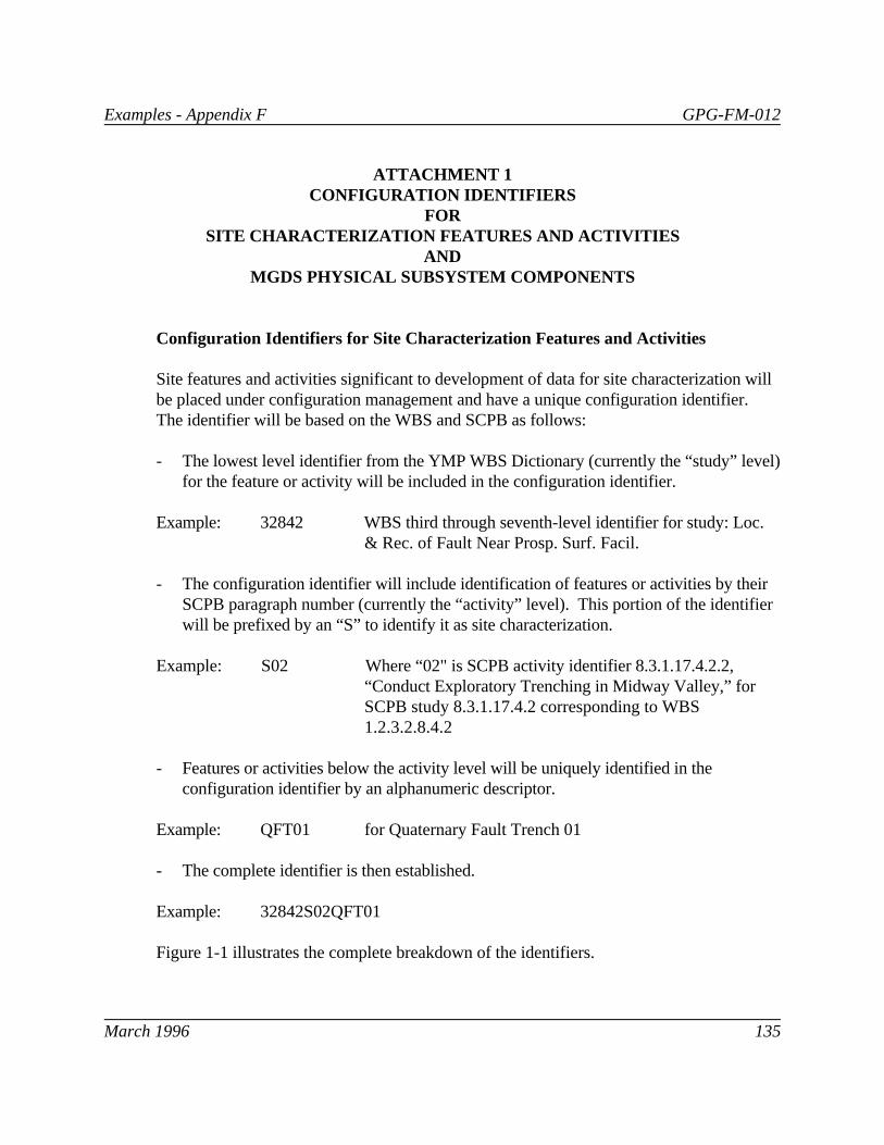
Examples - Appendix F GPG-FM-012
March 1996 135
ATTACHMENT 1CONFIGURATION IDENTIFIERS
FORSITE CHARACTERIZATION FEATURES AND ACTIVITIES
ANDMGDS PHYSICAL SUBSYSTEM COMPONENTS
Configuration Identifiers for Site Characterization Features and Activities
Site features and activities significant to development of data for site characterization willbe placed under configuration management and have a unique configuration identifier. The identifier will be based on the WBS and SCPB as follows:
- The lowest level identifier from the YMP WBS Dictionary (currently the “study” level)for the feature or activity will be included in the configuration identifier.
Example: 32842 WBS third through seventh-level identifier for study: Loc.& Rec. of Fault Near Prosp. Surf. Facil.
- The configuration identifier will include identification of features or activities by theirSCPB paragraph number (currently the “activity” level). This portion of the identifierwill be prefixed by an “S” to identify it as site characterization.
Example: S02 Where “02" is SCPB activity identifier 8.3.1.17.4.2.2,“Conduct Exploratory Trenching in Midway Valley,” forSCPB study 8.3.1.17.4.2 corresponding to WBS1.2.3.2.8.4.2
- Features or activities below the activity level will be uniquely identified in theconfiguration identifier by an alphanumeric descriptor.
Example: QFT01 for Quaternary Fault Trench 01
- The complete identifier is then established.
Example: 32842S02QFT01
Figure 1-1 illustrates the complete breakdown of the identifiers.

FIGURE A-1SITE CHARACTERIZATION CONFIGURATION IDENTIFIER
3 2 8 4 2 S 02 Q F T 0 1 - - -
CONDUCT EXPLORATORY TRENCHING IN MIDWAY VALLEYDESIGNATES AS SITE CHARACTERIZATION
QUARTERNARY FAULT TRENCH 01
WBS 7th LEVEL - LOC. & REC. OF FAULT NEAR PROSP. SURF. FACIL.
WBS 6th LEVEL - DATA COLLECTION AND ANALYSIS
WBS 5th LEVEL - PRECLOSURE TECTONICS
WBS 4th LEVEL - GEOLOGY
WBS 3rd LEVEL - SITE
p:\files\hill\graphics\ymp-a-1.prs

Examples - Appendix F GPG-FM-012
March 1996 137
Configuration Identifiers for MGDS Subsystem Components
Items comprising the physical structures, systems, components, and software of theMGDS will be placed under configuration management and be assigned a uniquecomponent identifier. The component identifier will be based on the WBS and MGDS-SRas follows:
- The lowest level identifier from the YMP WBS Dictionary applicable to thecomponent will be included in the identifier.
Example: 67100 WBS third through seventh-level identifier for: ESFUnderground Service Systems: Utilities, Services &Communications
- The uniform major system acquisition cost account identification code for physicalsubsystems from the MGDS-SR will be part of the unique identifier. This portion ofthe identifier will be prefixed by an “M” to identify it as a system requirement.
Example: M468 Where “468” is the code for ESF Underground UtilitySystem, Fire Protection System
- The code for the components major function will be part of the unique identifier.
Example: FCV Where “FCV” is the IEEE recommended code for a FlowControl Valve
- A unique address for the component within the subsystem will be part of thecomponent identifier.
Example: 1003
- The complete identifier is then established.
Example: 671000M468FCV1003
Figure 1-2 illustrates the complete breakdown of the identifier

FIGURE A-2MGDS SUBSYSTEM COMPONENT CONFIGURATION IDENTIFIER
6 7 1 0 0 M 4 6 8 F C V 1 0 0 3
CONDUCT EXPLORATORY TRENCHING IN MIDWAY VALLEYDESIGNATES AS MGDS SYSTEM
UNIQUE ADDRESS WITHIN SYSTEM/SUBSYSTEM
WBS 7th LEVEL - NONE
WBS 6th LEVEL - NONE
WBS 5th LEVEL - UTILITIES, SERVICES & COMMUNICATIONS
WBS 4th LEVEL - UNDERGROUND SERVICE SYSTEMS
WBS 3rd LEVEL - ESF
IEEE CODE FOR FLOW CONTROL VALVE
p:\files\hill\graphics\ymp-a-2.prs

Examples - Appendix F GPG-FM-012
March 1996 139
Subcomponent Identification
As design evolves or as operations and maintenance needs require, a further breakdown ofthe component into subcomponents can occur. The unique identifier for thesubcomponent consists of:
- The WBS identifier, MGDS-SR Code, and address portions of the parent componentunique identifier, per above
Example: 67100M708___1003with
The IEEE code for the subcomponent’s major function in place of the IEEE code for thecomponent’s major function.
Example: 67100M708FCI1003 Where “FCI” is the IEEE recommended code for theFlow Control Indicator associated with the FCV