configuration description, deployment, and lifecycle … · 2005-09-26 · configuration...
TRANSCRIPT
GFD-R-D.051 Editor: Configuration Description, Deployment and Patrick Goldsack, Hewlett Packard Labs Lifecycle Management Working Group September 9, 2005
Configuration Description, Deployment, and Lifecycle Management
SmartFrog-Based Language Specification
Status of this Memo This document provides information to the community regarding the specification of the Configuration Description, Deployment, and Lifecycle Management (CDDLM) Language. Distribution of this document is unlimited.
Copyright Notice Copyright © Global Grid Forum (2002, 2005). All Rights Reserved.
Abstract Successful realization of the Grid vision of a broadly applicable and adopted framework for distributed system integration, virtualization, and management requires the support for configuring Grid services, their deployment, and managing their lifecycle. A major part of this framework is a language in which to describe the components and systems that are required. This document, produced by the CDDLM working group within the Global Grid Forum (GGF), provides a definition of the CDDLM language that is based on the SmartFrog (Smart Framework for Object Groups) and its requirements.
CDDLM Specs There are five documents created by the CDDLM group. They are described in the text below. The CDDLM Foundation document sets the stage for the remaining documents by introducing the area, by describing functional requirements, use cases, and high-level architecture. It also compares this group with other working groups as well as with other related efforts in the industry. The SmartFrog Language spec describes a language primarily intended for configuration description and deployment. It is declarative, i.e. it supports attribute value pairs. Furthermore, it supports inheritance, references (including lazy), parameterization, predicates and schemas. It has the same functionality as CDL (see next paragraph), except that it is not XML-based.
GFD-R-D.051 September 9, 2005
SmartFrog language predates CDL and it was used as a model when creating CDL. The two languages will be compatible. CDL is primarily intended for machines, SmartFrog for humans.
The CDDLM Configuration Description Language (CDL) is an XML-based language for declarative description of system configuration that consists of components (deployment objects) defined in the CDDLM Component Model. The Deployment API uses a deployment descriptor in CDL in order to manage deployment lifecycle of systems. The language provides ways to describe properties (names, values, and types) of components including value references so that data can be assigned dynamically with preserving specified data dependencies. A system is described as a hierarchical structure of components. The language also provides prototype-based template functionality (i.e., prototype references) so that the user can describe a system by referring to component descriptions given by component providers. The CDDLM Component Model outlines the requirements for creating a deployment object responsible for the lifecycle of a deployed resource. Each deployment object is defined using the CDL language and mapped to its implementation The deployment object provides a WS-ResourceFramework (WSRF) compliant "Component Endpoint" for lifecycle operations on the managed resource. The model also defines the rules for managing the interaction of objects with the CDDLM Deployment API in order to provide an aggregate, controllable lifecycle and the operations which enable this process.
The deployment API is the WSRF-based SOAP API for deploying applications to one or more target computers. Every set of computers to which systems can be deployed hosts one or more "Portal Endpoints", WSRF resources which provide a means to create new "System Endpoints". A System Endpoint represents a deployed system. The caller can upload files to it, then submit a deployment descriptor for deployment. A System Endpoint is effectively a component in terms of the Component Model specification -it implements the properties and operations defined in that document. It The deployment API is the WSRF-based SOAP API for deploying applications to one or more target computers. Every set of computers to which systems can be deployed hosts one or more "Portal Endpoints", WSRF resources which provide a means to create new "System Endpoints". A System Endpoint represents a deployed system. The caller can upload files to it, then submit a deployment descriptor for deployment. A System Endpoint is effectively a component in terms of the Component Model specification -it implements the properties and operations defined in that document. It also adds the ability to resolve references within the deployed system, enabling remote callers to examine the state of components with it.

GFD-R-D.051 September 9, 2005
Table of Contents Table of Contents .................................................................................................................................. 3 List of Figures........................................................................................................................................ 4 1 Introduction .................................................................................................................................. 5 2 CDDLM-WG and the Purpose of this Document ...................................................................... 5 3 The CDDLM Notation................................................................................................................. 5
3.1 Background.......................................................................................................................... 5 4 Requirements for the language.................................................................................................... 6 5 Concrete Syntax ........................................................................................................................... 7
5.1 Attributes, Attribute Lists and Streams ............................................................................. 7 5.2 Component Descriptions .................................................................................................... 8 5.3 Types vs. Prototypes ......................................................................................................... 10 5.4 References ......................................................................................................................... 11
5.4.1 Reference Elimination – Resolution............................................................................ 12 5.4.2 Prototype References.................................................................................................... 12 5.4.3 Placement References .................................................................................................. 13 5.4.4 Link And LAZY Link References............................................................................... 14
5.5 Comments .......................................................................................................................... 16 6 Parameterization......................................................................................................................... 16 7 Include Files ............................................................................................................................... 17 8 Main ............................................................................................................................................ 18 9 Resolution – Semantics For The CDDLM Notation............................................................... 19
9.1.1 Type Resolution............................................................................................................ 20 9.1.2 Placement Resolution................................................................................................... 20 9.1.3 Link Resolution ............................................................................................................ 22
10 Functions..................................................................................................................................... 22 10.1 concat ................................................................................................................................. 23 10.2 vector.................................................................................................................................. 23 10.3 append................................................................................................................................ 23 10.4 formatString....................................................................................................................... 24 10.5 sum..................................................................................................................................... 24 10.6 product ............................................................................................................................... 24 10.7 random ............................................................................................................................... 25 10.8 next..................................................................................................................................... 25 10.9 date ..................................................................................................................................... 25
11 Schemas ...................................................................................................................................... 26 12 Summary of CDDLM Language Processing............................................................................ 29 13 The CDDLM Syntax................................................................................................................. 30 14 The CDDLM Notation Lexical Rules....................................................................................... 30 15 Encoding ..................................................................................................................................... 32 16 Security Considerations ............................................................................................................. 33 17 Editor Information...................................................................................................................... 33 18 Contributors ................................................................................................................................ 33 19 Acknowledgements .................................................................................................................... 33 Intellectual Property Statement .......................................................................................................... 33 Full Copyright Notice ......................................................................................................................... 33 References............................................................................................................................................ 34

GFD-R-D.051 September 9, 2005
20 An example deployment of a simple Grid application ............................................................ 35 20.1 Scenario: Tuple-space dispatch of stock analysis workload. ......................................... 35 20.2 Cross-application components ......................................................................................... 35
20.2.1 Java Processes .......................................................................................................... 35 20.2.2 Tuple Space .............................................................................................................. 36 20.2.3 Worklet ..................................................................................................................... 36 20.2.4 Worklet Container.................................................................................................... 36 20.2.5 Security ..................................................................................................................... 37 20.2.6 Database.................................................................................................................... 37 20.2.7 dateTime ................................................................................................................... 37 20.2.8 Bulk Node Deployer ................................................................................................ 37
20.3 Worklets............................................................................................................................. 38 20.3.1 Past History Worklet................................................................................................ 38 20.3.2 Predictor Worklet ..................................................................................................... 38 20.3.3 Data Feed Worklet ................................................................................................... 38
20.4 Test Data............................................................................................................................ 39 20.5 Test Harness ...................................................................................................................... 39
20.5.1 Test Worklet Container ........................................................................................... 39 20.5.2 Test Harness ............................................................................................................. 40
20.6 Liveness ............................................................................................................................. 42 20.7 Scaling ............................................................................................................................... 42
List of Figures Figure 1. CDDLM Language Use and Relationship with other Components ................... 6 Figure 2. Use of Inheritance in Templates ..................................................................... 10 Figure 3. Scope of References....................................................................................... 12
GFD-R-D.051 September 9, 2005
1 Introduction Deploying a complex, distributed service presents many challenges related to service configuration and management. These range from how to describe the precise, desired configuration of the service, to how we automatically and repeatably deploy, manage and then remove the service. This document addresses the description challenges, while other challenges are addressed by the follow-up documents . Description challenges include how to represent the full range of service and resource elements, how to support service "templates", service composition, correctness checking, and so on. Addressing these challenges is highly relevant to Grid computing at a number of levels, including configuring and deploying individual Grid Services, as well as composite systems made up of many co-operating Grid Services.
2 CDDLM-WG and the Purpose of this Document The CDDLM WG addresses how to: describe configuration of services; deploy them on the Grid; and manage their deployment lifecycle (instantiate, initiate, start, stop, restart, etc.). The intent of the WG is to gather researchers, developers, practitioners, and theoreticians in the areas of services and application configuration, deployment, and deployment life-cycle management and to explore the community need for a broader effort in this area. The target of the CDDLM WG is to come up with the specifications for CDDML a) language, b) component model, and c) basic services. This document represents one of the two CDDLM language specifications. This specification is based on the expertise with SmartFrog language developed at HP Labs. The other language will be entirely XML based. The two language specifications will be compatible. Both languages will be declarative, i.e. they will support attribute value pairs. They will furthermore support inheritance, references (including lazy), parameterization, predicates and schemas. The rest of the document describes the features supported in the SmartFrog-based CDDLM language. This document describes the configuration language. It does not describe the binding of the language to any system that supports the language. Such bindings may introduce specific attributes, functions, predicates, components or other constructs that map from a general configuration language to a specific role of the language, or a specific implementation of a runtime.
3 The CDDLM Notation 3.1 Background The CDDLM notation has been designed to provide users of the CDDLM framework with a simple, yet powerful, attribute description language. The reason that the notation has been developed, rather than merely using XML, is that a number of features are required that are not directly supported by XML, though they could be encoded, and that use of these features requires the use of human-friendly syntax. The syntax is derived from the tried and tested first generation SmartFrog notation [1] and it makes a few minor changes to reflect the core differences between it and CDDLM.
GFD-R-D.051 September 9, 2005
There is an XML binding for the language to go along with this form of the language design, providing support for those who prefer to use that syntax. This syntax is provided in [3].
The CDDLM component model in no way depends on the nature of this notation. Indeed there are relatively few aspects of the notation that are specific to the CDDLM framework. Most of the language is simply for defining collections of attributes. The framework uses these attributes to achieve the desired configuration effect. The details of these attributes and their impact on the framework are left to other CDDLM documents. This document concentrates only on the use of the notation for defining attributes.
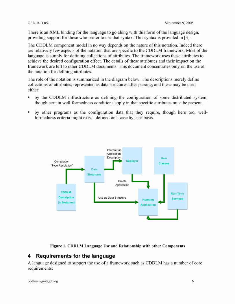
The role of the notation is summarized in the diagram below. The descriptions merely define collections of attributes, represented as data structures after parsing, and these may be used either: • by the CDDLM infrastructure as defining the configuration of some distributed system;
though certain well-formedness conditions apply in that specific attributes must be present
• by other programs as the configuration data that they require, though here too, well-formedness criteria might exist - defined on a case by case basis.
CDDLM
Description
(in Notation)
Data
Structures
Run-Time
ServicesRunning
Application
Use as Data Structure
Compilation
“Type Resolution”
Deployer
Create
Application
Interpret as
Application
Description User
Classes
Figure 1. CDDLM Language Use and Relationship with other Components
4 Requirements for the language A language designed to support the use of a framework such as CDDLM has a number of core requirements:
GFD-R-D.051 September 9, 2005
1. The language is primarily designed to define configuration data for use by the framework services, defining the configuration of the resources and software components that define the Grid service to be deployed.
2. The language will be used for such a wide variety of services and resources, and of such complexity, that a language must be both readable and support a number of abstraction mechanisms such as inheritance and parameterization.
3. The language must support the notion of templating, the ability to provide patterns of configuration that may be specialized at time of use.
4. The language must support a way of checking the use of templates to ensure that they are being applied in an appropriate way.
5. The language must support the notion that data is available at different phases of a service deployment – for example some data is available at time of template definition or use, other data is only available at run-time. An example of the former may be data regarding the performance of web servers required for a service whilst an example of the latter may be the specific type of the nodes on which the servers are to run, and hence the precise number of servers required to meet the required performance.
5 Concrete Syntax 5.1 Attributes, Attribute Lists and Streams A CDDLM description consists of an ordered collection of attributes. The attributes are ordered because several of the operations in the CDDLM framework require an order, for example the order in which the configuration should be instantiated.
Each attribute has a name and a value, this value being either a basic value (integer, string, etc), or an ordered collection of attributes known as a component description. This recursion provides a tree of attributes, the leaves of which are the basic values. A value may also be provided by reference to another attribute. This is described by the following BNF, where Stream indicates the entry point to a CDDLM language parser.
Stream ::= AttributeList AttributeList ::= AttributeListElement* AttributeListElement ::= Attribute | #include string (1) Attribute ::= Name Value (2) Name ::= BaseReference | -- (3) Value ::= ; | Basic ; | ComponentDescription | [LAZY] BaseReference ; (4) Basic ::= Number | String | Boolean | Vector Vector ::= [ ] | [ Basic (, Basic)* ]
From this, it is clear that the input to the parser is a collection of attributes, each named and having an optional value (2). If the value is not present, (the first alternative in (4)) the value is defined to be the string containing the name of the attribute. Thus, the following two attribute definitions are equivalent.
foo; foo "foo";

GFD-R-D.051 September 9, 2005
The reason for providing this feature is to enable the use of attributes where the presence of the attribute is what is important, not its value.
The syntax for a name will be covered later, but for now it can be considered to be either a simple sequence of letters and digits, starting with a letter, or the double-hyphen "--" (3). The double hyphen is for use at times when the attribute name is not important (a new unique name is generated and used). This is particularly useful with the function syntax described in Section 10.
Include files (1) are covered in more detail in section 7, but in general they consist of parseable CDDLM text which are parsed as attribute lists and unpacked into place within the container attribute list. The syntax for the basic values is best given by example.
Integer: 345 Long: 65325L Float: 34.76 Double: 1534.456D String: "this is a string" Multi-line String: ## This is a string Over many lines # Boolean: true Vector: [3.67, [34, 53, 1], ["string", 34], []] Binary Data: @base64data@
Consequently, an example of a piece of CDDLM text is as follows portNum 4074; hostname "ahost.cddlm.org"; isHighPriority false; validUsers ["fred", "harry", "mike"]; data @234s4Txx@
defining four attributes with the appropriate values. 5.2 Component Descriptions Attributes may have values that are collections of other attributes, known as component descriptions. They obtain their name from the fact that they may be interpreted by the framework as the description of a component, though they may equally be used to describe structured data.
A component description consists of two parts, a reference to another component description to act as a source of attributes, and a collection of attributes that are then added to, or override, the attributes of the referenced collection. The syntax is:
ComponentDescription ::= extends BaseComponent BaseComponent ::= [Reference | NULL] ( ; | { AttributeList } )
Both the reference and the attribute list are effectively optional. If neither is present, the resultant attribute list is defined to be empty. The syntax is most easily explained through an example:
SFService extends { // an implicit extension of NULL portNum 4047; hostname "ahost.Cddlm.org"; administrators ["patrick"]; }

GFD-R-D.051 September 9, 2005
UseableService extends SFService { //an extension of the previous component portNum 4048; // override the definition of portNum users ["fred", "harry"]; // add a new attribute }
The text consists of two attributes, both of which have values that are collections of attributes. The second of these, UseableService, is defined as an extension of the first, SFService, with two attributes added to or overwriting those inherited. The text is semantically identical to the following:
SFService extends { portNum 4047; hostname "ahost.Cddlm.org"; administrators ["patrick"]; } UseableService extends { portNum 4048; hostname "ahost.Cddlm.org"; administrators ["patrick"]; users ["fred", "harry"]; }
Note that the attributes in a component description are ordered and that when an attribute is overwritten it maintains its position, but when it is a new attribute it is added to the end. The process of expansion of the inheritance in this way is known as Type Resolution and is explained further below.
Note also that the parsed stream is considered to be in an implicit, anonymous (i.e. not named in an outer component description), component description known as ROOT.

GFD-R-D.051 September 9, 2005
portNum 4047;
hostname “pgoldsac.hpl.hp.com”;
admininstrators [“patrick”];
portNum 4048;
users [“fred”, “harry”];
Implicit Root Component Descriptoon
SFService
UseableServce
extends
NULL
extends
Implicit Root Component Description
UseableServce
extends
portNum 4048; hostname “pgoldsac.hpl.hp.com”;admininstrators [“patrick”];users [“fred”, “harry”];
portNum 4047;
hostname “pgoldsac.hpl.hp.com”;
admininstrators [“patrick”];
SFService
extends
NULL
NULL
original semantic equivalent
Figure 2. Use of Inheritance in Templates
The example is also shown in the diagram. It clearly shows that there are two kinds of relationship between component descriptions. One is the containment relationship, where a component description contains an attribute that is itself a component description. The second is the inheritance or extension relationship. This second class of relationship is one that can be transformed, by type resolution, to an equivalent one containing no extension (also indicated by the NULL extension). Whilst the extension relationship is merely a convenient way of defining attributes, the containment hierarchy is a more fundamental construct. It should be noticed that that containment hierarchy effectively provides a naming scheme by which attributes may be referenced. In this it is similar to other such named hierarchies, such as directory hierarchies common in files systems. 5.3 Types vs. Prototypes CDDLM does not define types for attributes and components. Rather it defines the notion of a prototype. Each attribute whose value is a component description may be considered as a prototype for another: it may be taken and modified as appropriate to provide the value for the new attribute. The mechanism for this is the extends construct.
Any attribute whose value is a component description may be, at a later juncture, selected and modified to provide a new component description to be bound to a name. This new attribute may be further modified by subsequent attributes. In this way, it is possible to provide partial

GFD-R-D.051 September 9, 2005
definitions, with default values for attributes, to be completed or specialized when used. This provides a simple template mechanism for components.
Consequently, there are no separate spaces of types and instances; every component is logically an instance, but may also be a prototype for another. However, it is clear that in providing descriptions, some components will be defined with the intention that they be used as prototypes for other components, whilst others will be defined without that expectation. Whilst this may appear strange in the first instance, it turns out to be one of the main strengths of the CDDLM notation. 5.4 References References may occur in three places in the syntax: as the name of an attribute – known as a placement, as a reference to the extended component (the prototype) of a component description, and as an attribute value referring to another attribute whose value is to be copied – known as a link.
The primary purpose of a reference is to indicate a path through the containment hierarchy defined by the components. In this, it is similar to the notion of path common in file systems in operating systems such as Linux. A path defines a traversal of the directory hierarchy, a structure similar to the component hierarchy.
The syntax for references is as follows: BaseReference ::= ReferencePart (: ReferencePart)*
ReferencePart ::= ROOT | PARENT | WORD | ATTRIB WORD | THIS
Thus, a reference is a colon-separated list of parts each of which indicates a step in the path through the containment tree. Examples of references are:
PARENT:PARENT:foo:bar ATTRIB a:b ROOT
The general rule for the interpretation of a reference is that the reference is evaluated in a context (a component description somewhere in the description containment tree), and that each step moves the context to a possibly different component for the remainder of the reference to be evaluated. This is equivalent to path evaluation in a Linux file system, the path is evaluated in a current directory, and each part of the path moves the context to another directory.
The semantics of each of the reference parts is as follows: starting at component in which the reference is defined…
• PARENT - move context to the parent (container) component if it exists, fail otherwise (c.f. Linux “..”)
• WORD - look for the attribute named “word” in the current context, fail otherwise
• ATTRIB WORD - look for the attribute named “word” in the current context or anywhere in the containment hierarchy (the closest is chosen), move to the context defined by this attribute, fail if no attribute is found in the containment hierarchy
• ROOT - switch context to the outer-most component (normally the implicit root component - c.f. Linux “/ “)

GFD-R-D.051 September 9, 2005
• THIS – the current context (c.f. Linux “.”)
Some examples of references (in this case link references) are as follows:
Figure 3. Scope of References
The arrows in the left-hand text show the path followed as the references are resolved to obtain the referenced attribute values, noting that the resolution of ref3 will follow the resolution of ref2. The contexts traversed as the resolutions progress are shown boxed and the right-hand text shows the result of resolving the three links. The above rules determine the general interpretation of references. However, each of the syntactic contexts has its own slight semantic variation; these variations appear in the detailed definition of the semantics for references. 5.4.1 Reference Elimination – Resolution The key to the semantics of the CDDLM notation is the process by which references are eliminated. This is necessary for each of the three syntactic locations where references may occur – prototype references, placement references and link references. The process by which references are eliminated is known as reference resolution. However, each type of reference has a different notion of resolution and so each has a specific resolution action – known respectively as type resolution, placement resolution and link resolution. This last name is historically also known as deployment resolution; this old name appears in parts of the API and is kept for backward compatibility. The resolution steps are described in more detail in the next few sub-sections, and then revisited as a whole to examine their interaction with each other. 5.4.2 Prototype References References to prototypes, as defined in the following syntactic context,
Component ::= extends [LAZY] BaseComponent
GFD-R-D.051 September 9, 2005
BaseComponent ::= [Reference] ( ; | { AttributeList } )
are resolved as described above except in one respect: if the reference to the prototype consists of a single WORD part, it is interpreted as ATTRIB WORD.
Thus, the following are equivalent Foo extends Bar { …} Foo extends ATTRIB Bar {…}
This is to provide a greater degree of convenience when referring to a prototype as these are most often defined in the outermost implicit root context, and frequently defined in an included file. Using this re-interpretation using ATTRIB, rather than adding an implicit ROOT reference part to the front, ensures that global definitions of prototypes at the top level may be locally overridden if required. The following example demonstrates most of the situations:
Foo extends { a 1; } Bar extends { foo extends Foo; } Baz extends { Foo extends { b 2; } foo1 extends Foo; // recall - this is equivalent to ATTRIB Foo foo2 extends ROOT:Foo; foo3 extends PARENT:Foo; foo4 extends PARENT:PARENT:Foo; }
After type resolution, which includes the merging and overwrite of attributes as described in section 5.2, the example is equivalent to:
Foo extends { a 1; } Bar extends { foo extends { a 1; } // ATTRIB Foo finds the outermost } Baz extends { Foo extends { b 2; } foo1 extends { b 2; } // ATTRIB Foo finds the closest enclosing foo2 extends { a 1; } // ROOT:Foo finds the one in the root foo3 extends { b 2; } // PARENT:Foo finds that in the parent foo4 extends { a 1; } // PARENT:PARENT:Foo finds that in the root (in this case) }
5.4.3 Placement References An attribute’s name may be a reference, as described in the syntactic clauses
Attribute ::= Name Value Name ::= BaseReference
This is not completely accurate, as the syntax in fact limits references to being a reference containing WORDS, the other reference parts are considered erroneous.
GFD-R-D.051 September 9, 2005
The resolution of the reference is again largely as described above, with the following modification.
The last reference part of the reference must be a WORD and is treated differently. This word part is not strictly part of the reference, but is used to identify the name of an attribute that is to be created (as opposed to referenced) in the context of the prefix part of the name reference. Thus in the attribute definition
foo:baz:bar 42;
the foo:baz is a reference to a location, bar is the name of the attribute to be created in that context.
In most cases, the name consists only of that final WORD leaving the prefix reference empty, indicating the current context. Thus, the attribute is defined in that current context. Where a non-empty reference prefixes the final word, the reference is used to determine the appropriate context and the attribute with the given name is placed into that context.
Consider the example Service extends { portNum 4089; } Service:portNum 4074; Service:hostname "ahost.cddlm.org";
The prefix reference Service: is de-referenced to indicate the Service attribute. The two prefixed attributes are therefore placed within that reference context, overriding or placed at the end of the context as appropriate. Thus, the example is roughly equivalent to the following (there are some differences in their behaviour as prototypes):
Service extends { portNum 4074; hostname "ahost.cddlm.org"; }
The act of placing the attributes into a location is known as placement resolution, and it occurs simultaneously with the removal of the reference-prefixed attribute from its defining context. Placement of attributes can lead to a great deal of confusion if not used properly. It reacts in interesting ways with type resolution; this interaction is explained in the section on resolution. 5.4.4 Link And LAZY Link References Frequently, attributes need to take on the same values as other attributes. This can be for many reasons: • to avoid repetition of values at many points in a description making it easier to maintain that
description
• to hide the structure of the description to a program; to bind parts together by reference rather than composition.
• to provide a means of simple parameterization; explained further in the section 6.

GFD-R-D.051 September 9, 2005
This association between the value of one attribute and that of another is defined by providing a reference in the place of a value of the attribute. This reference is resolved relative to the context at the point of definition. Consider the following example, in which a server and a client both need to know the TCP/IP port on which the server will listen.
System extends { server extends { portNum 4089; } client extends { portNum ATTRIB server:portNum; } }
The system contains a server and a client. The server and client both have an attribute portNum, with that of the client being defined as a link to that of the server.
There is a resolution step, known as link resolution (and occasionally deployment resolution), which replaces references by the values that they reference. During the resolution phase, chains of links are resolved appropriately. In the above example, the definition of System is equivalent to the following:
System extends { server extends { portNum 4089; } client extends { portNum 4089; } }
Consequently, both the server and client share the same value and maintenance is eased in that should the port number need be changed, this need happen in only one place in the description.
It is frequently the case that the link itself is required as a value; i.e. the link should not be resolved to the value that it might refer to within the description. This reference may then be used within a CDDLM application after deployment, for resolution at run-time rather than at the time of parsing the description.
In order to provide a reference value, rather than have it resolved to the value of another attribute during link resolution, the keyword LAZY may be prefixed to the link to indicate that the link resolution should not resolve the link. An example of this is:
System extends { server extends { foo 42; } client extends { myServer LAZY ATTRIB server; } }

GFD-R-D.051 September 9, 2005
In this case, the client’s attribute myServer is a reference to the server, not a copy of the server component. As is, resolution will have no effect, as the link will be left to be the attribute value. If the keyword LAZY had not been present, the following would have been the result of resolution:
System extends { server extends { foo 42; } client extends { myServer extends { foo 42; } } }
The word LAZY is an indication that it will be resolved at run-time – so far as the notation is concerned, this means that the link is the value. 5.5 Comments The CDDLM notation follows most modern languages in providing both end-of-line comments and multi-line bounded comments. The syntax for these is identical to that of Java, namely
// this is a comment to the end of the line /* this is a comment which is terminated by */
6 Parameterization When extending a prototype, it is normal to override the values of certain attributes to customize the prototype to its actual use. The simplest way is to extend with the replacement attribute – however this only works for a top-level attribute. Modification of attributes deep in the structure requires the placement of the overriding attribute into the correct context, as in the example:
Service extends { hostname "localhost"; portNum 4567; } ServicePair extends { service1 extends Service ; service2 extends Service ; } main extends ServicePair { // user needs to know structure of ServicePair service1:hostname "riker.cddlm.org"; service2:hostname "ackbar.cddlm.org"; }
This works adequately, but it has the disadvantage that the use of the ServicePair prototype requires knowledge of its structure, though it does have the advantage that any attribute in the structure may be changed if necessary. However, under normal circumstances, there are attributes whose values are expected to change, and others that are not. Under these circumstances, it would be good if the description could be parameterized on these attributes. However, the normal form of parameterization as provided in programming language functions

GFD-R-D.051 September 9, 2005
is not a good fit to the CDDLM notation semantics – so the language provides a way of finding a way of hiding the structure of a description and making it easier to override “deep” attributes.
This technique, more of a pattern for the use of links, is shown in the following example: Service extends { hostname "localhost"; // default value portNum 4567; } ServicePair extends { s1Host "localhost"; // provide default value s2Host "localhost"; service1 extends Service { hostname ATTRIB s1host; } // lift attribute service2 extends Service { hostname ATTRIB s2host; } // ditto } main extends ServicePair { // user needn’t know structure of ServicePair s1host "riker.cddlm.org"; s2host "ackbar.cddlm.org"; }
It is clear that the use of ServicePair requires only the extension with top-level attributes to set the attributes deeply defined in the Service prototype. This pattern, of the use of links lifting an attribute value to one provided in the outermost context, is called the parameterization pattern and is very frequently used.
Note that if a default value for a lifted attribute is not given within the description (in this case ServicePair provides defaults for both the lifted attributes s1Host and s2Host), a deploy resolution error will occur if the parameter is not provided at time of use, since the value to resolve the link will not be found.
7 Include Files A stream of text may reference include files at certain points in that text. Unlike a C-language include file, though, the include file is not merely textually embedded into the original stream. Rather the include file is itself parsed (and must be syntactically correct) as a stream in its own right. Every stream must parse as a collection of attribute definitions, and this is equally true of the include files.
Include files may only be used within attribute lists (i.e. at the top level or within a component definition). The collection of attributes from the include file are simply added to the attribute list being parsed in the container stream. Consider the following example:
• file foo.cddlm contains:
foo extends { a 42; }
• the primary stream is:
#include "foo.cddlm" system extends {

GFD-R-D.051 September 9, 2005
myFoo extends foo; #include "foo.cddlm" }
After the parsing is complete (but before type resolution), the following is obtained: foo extends { a 42; } main extends { myFoo extends foo; foo extends { a 42; } }
It should be noted that because includes may occur within other component descriptions, this may be used as a naming mechanism to prevent clashes of attribute name within multiple include files. Consider
• file foo1.cddlm contains
foo extends { a 42; }
• file foo2.cddlm contains
foo extends { b 42; }
• the primary stream contains
foo1 extends { #include "foo1.cddlm" } foo2 extends { #include "foo2.cddlm" } main extends { bar extends ATTRIB foo1:foo; baz extends ATTRIB foo2:foo; }
If the includes had not been buried within separately named components, but both had been included into the top level, only the second of the two mentioned foo attributes would have been available for extension. The second would have overridden the first.
8 Main A stream contains a whole collection of attributes at the top level. Most are merely there to act as building blocks – prototypes for building others. Typically, there is only a single attribute that is the essence of the description – that which describes the desired configuration and is not merely a building block on the way. By convention in CDDLM, the reserved attribute name main defines this special attribute and all the tools provided respect this convention.
Thus, when a stream is parsed to an attribute set, the top-level attribute main defines the system; the rest are ignored, apart from providing definitions for extensions and other resolutions. This is equivalent to the Java language use of the “special” method main(…) to indicate the entry point to a program. The entry point to a configuration description is main.

GFD-R-D.051 September 9, 2005
Thus in the following example, the attributes def1, def2 and def3 are only present for the purposes of defining main, and it is only this last attribute that represents the actual configuration description.
def1 extends {…} def2 extends { foo extends {…} bar extends {…} } def3 extends {…} main extends { d1 extends def1; d2 extends def2; d3 extends def3; }
9 Resolution – Semantics For The CDDLM Notation Resolution is the process by which the raw CDDLM definitions, with their extensions, placements and links, are turned into the set of attributes that they semantically represent. There are two ways of representing the semantics, both roughly equivalent.
1. By defining how the value of an attribute identified by a reference is obtained from a description; defining the semantics by providing a function from reference to value for all possible references. This would be the ideal way of defining the semantics, however for pragmatic reasons the semantics are less “pure” than may be desired and it is hard to define the semantics in this way. Two aspects that are particularly hard to define in this style are the order of type resolution and the placement of attributes.
2. By defining a set of transformation rules that eliminate the complexity of the typing (by expansion), placement (by relocation) and linking (by value copy), resulting in a normalized form of a description containing merely a hierarchical set of attribute lists.
Either of these two forms of semantic definition would do, however the definition of the semantics through transformation has a distinct advantage: these transformations are required in practice and hence are implemented within the CDDLM system. Thus, an understanding of these transformations is essential to the use of CDDLM.
The three transformation steps are known in CDDLM as resolution steps. These are respectively type resolution, placement resolution and link resolution. They are carried out in that order: first the types are expanded, then attributes placed into the correct context from the context in which they were defined, and finally links are resolved.
It should be noted that the entire description is type and place resolved, but only the top-level main attribute is normally link resolved. In general, if the other top-level attributes are link resolved, errors will occur; they are only present to be available as prototypes. Further, unnecessary work will have been done.
The algorithms defined here for the transformations are the result of much empirical experimentation – other transformation algorithms produce more regular semantics, others are

GFD-R-D.051 September 9, 2005
more efficient. However, those presented here are a balance between performance and semantic simplicity. They provide a great deal of control over the semantics of the resolution process. 9.1.1 Type Resolution Type resolution is the expansion of the prototype reference optionally provided in the extends part of a component description. The syntactic form for a component description is roughly
name extends Reference { AttributeList }
The reference refers to a prototype that is to be extended by the attributes in the provided attribute list. This process of type resolution is a depth-first pass over the root component description, in the order of definition of the attributes.
• Copying the prototype indicated by the reference, creating a new component description
• Replacing the attribute values of the new component description also mentioned in the attribute list (i.e. the value, but not the order, changes)
• Adding the remaining attributes at the end of the new prototype
• Type-resolving each of the component description’s attributes if they are component descriptions
If the prototype reference indicates a component description that is not yet resolved, it resolves it first before copying: i.e. each type resolution is carried out with respect to the location where the prototype is defined. The other point to note is that if the reference is only a word, it is interpreted as ATTRIB word for the purposes of locating the prototype for the component description. If, at the end of the process, one or more component descriptions have failed to resolve, in that their prototypes cannot be found, the whole resolution process ceases and an exception is thrown indicating the missing prototypes and the locations at which they are referenced. Note that any references that may be copied as part of the extension process are not modified. Hence, copied placements are now relative to the new location and copied links similarly. Prototype references are never copied since a prototype is always resolved before copy.Placement Resolution Placement resolution is the process by which the attributes are placed into the correct location. Attributes are named, and this name may contain a reference to a component description as well as the name by which it is to be known in that component description. If the reference is not present, the attribute is assumed to be in the correct component description as defined.
Thus in the example attribute declaration: foo:bar:baz 42;
The foo:bar: defines the target component description, and baz defines the name for the attribute in that component description. Placement resolution is the transformation process that results in the attribute definitions being removed from their point of definition and placed in the target component descriptions. The process is a multi-pass process, for each pass:
GFD-R-D.051 September 9, 2005
• traverse the component description hierarchy
o depth first
o visiting the attributes in the order of definition (as determined by type resolution)
• each attribute visited is examined, if it should be placed elsewhere – try to do so, if it fails – leave as is.
The pass is repeated until one of the following occurs: • there are no placements left to transform
• no placements have been successfully carried out, and at least one placement has failed
In the first instance, the placement resolution has successfully completed, the second it has not and an error is generated.
To see why multiple passes are necessary, consider the following: foo extends { a 21; } foo:bar:a 42; foo:bar extends { b 34; }
In the first pass, the attribute foo:bar:a is first to be placed, but it fails since foo does not yet contain foo:bar as a component description. Also in the first pass, but later since it is defined later, foo:bar is placed, giving
foo extends { a 21; bar extends { b 34; } } foo:bar:a 42;
This leaves a placement incomplete so a second pass is required. This time it succeeds, resulting in
foo extends { a 21; bar extends { b 34; a 42; } }
This order dependency does not have much of an effect, except for when two identically named attributes are placed into the same component description. At this point understanding the order of resolution becomes important. Since placement resolution is carried out after type resolution, the following consequences should be noted:
GFD-R-D.051 September 9, 2005
• As type resolution is carried out before placement, attributes placed into a prototype will not be inherited by those extending the prototype.
• Again, as type resolution is carried out before placement, do not place an attribute that is to be used as a super-type; it will not be found.
• Wherever possible, placement should be restricted to referencing downwards into a structure from the point of attribute definition. Descriptions can be very hard to understand if PARENT, ROOT or ATTRIB are used in a placement reference; this particularly so within a component description to be used as a type. As a consequence, this release of CDDLM does not permit these reference parts to be used in a placement.
The reason why type resolution is done before placement resolution is that the normal use for placement is to “fill-in” empty “attribute slots” in a prototype. As each instance of the prototype will in general need differently filled slots, placement must be done after the type has been resolved for each instance.
Note that placement of attributes whose values are links do not modify the links to correct for the new location. Thus, links are resolved with respect to where they are placed, not where they are defined. 9.1.3 Link Resolution Link resolution is the most straightforward of the three forms of resolution; all links are resolved in their location after type and place resolution, and the referenced values copied, replacing the link as the value of the attribute. There are a number of minor points to note:
• Only links that are not LAZY are resolved; those that are LAZY are left unresolved with the link itself being the value.
• In resolving a link, the value of the attribute referenced is copied. If the value of the attribute is a link, this is first resolved and the result copied.
• Links are always resolved in the contexts in which they are located after the type and placement resolution phases are over, not necessarily those in which they were defined.
• Links referring to an attribute whose value is a LAZY link will copy the LAZY link unchanged, this being the attribute’s value.
10 Functions CDDLM provides users with a small number of predefined functions to improve the expressiveness of the descriptions.
Functions appear, to the language, as predefined component descriptions that may be extended; the parameters are given as named attributes within the body of that description. For example, a use of the string concatenate function is
#include "/org/cddlm/functions.cddlm" // the standard functions val 42; myString extends concat {

GFD-R-D.051 September 9, 2005
-- "the meaning of life is "; -- ATTRIB val }
that results in the value of the myString attribute being "the meaning of life is 42". The names of the attributes have no effect in this case, the strings being concatenated in the order of definition, but may be important for some other functions.
Functions are evaluated inner-first, providing for the nesting of function application, and are evaluated after all the other resolutions steps have be completed. The definitions are themselves affected by these resolutions. Thus, a function may be extended with the resultant extension also being a function.
The pre-defined function templates are defined available by including the functions.sf file as follows:
#include "org/cddlm/functions.sf"
This file defines the list of functions that are described below. 10.1 concat The concatenate function takes each of its attribute parameters and concatenates them in the order of definition. These attributes are converted to strings using the toString() Java method. An example of the use of the concatentate function is:
myString extends concat { a "the meaning of life is "; b 42; c extends concat { a " by "; b "Douglas Adams"; } }
This results in the string "the meaning of life is 42 by Douglas Adams". 10.2 vector The vector function takes each of its attribute parameters and puts them together into a vector. An example is
myString extends vector { -- "the meaning of life is "; -- 42; -- extends vector { -- " by "; -- "Douglas Adams"; } }
This results in the vector [ "the meaning of life is", 42, [ "by", "Douglas Adams"]]
10.3 append The append function is similar to the vector function, except that all parameters must be vectors and these are expanded in-line. The difference can be seen by considering the same example

GFD-R-D.051 September 9, 2005
myString extends vector { -- ["the meaning of life is "]; -- [42]; -- extends vector { -- " by "; -- "Douglas Adams"; } }
This results in the vector [ "the meaning of life is", 42, "by", "Douglas Adams"]
10.4 formatString FormatString is a function that takes a format string and a set of parameters and creates a resultant string which has the values of the parameters embedded. The format string attribute itself should be named format and the various parameter strings should be named sx where x is a single digit. The format string should identify the places where the various parameter strings should be embedded using the characters “$x” for a single digit x. An example is
myString extends formatString { format "the meaning of $2 is $1"; s1 42; s2 "life"; }
The attributes may of course be links to other values, but not LAZY links as these are not resolved in time for the function phase. 10.5 sum The sum function sums each of its attributes type-caste to integers, failure will result in an exception. The order, of course, is irrelevant. An example of the use of the sum function is:
val1 34; val2 45; num extends sum { a ATTRIB val1; b 345; c ATTRIB val2; }
This will result in num being set to 424. 10.6 product The product function multiplies each of its attributes type-caste to integers, failure will result in an exception. The order is irrelevant. An example of the use of the product function is:
times10 extends product { ten 10; } myNum extends times10 { val 34; }

GFD-R-D.051 September 9, 2005
This will result in myNum being set to 340. 10.7 random The random function, which in truth is not really a function since it returns a different value for each invocation, returns a random number as follows:
• if the attribute integer is set to true, an integer between attributes min and max is returned, otherwise a floating point value between 0 and 1. The default values for min and max are 0 and 10 respectively.
• if the attribute seed is provided, and the random number generator has not yet been initialized, that seed is used.
Examples of the use of the random are: dice extends random { integer true; min 1; max 6; } myConfig extends … { throw1 extends dice; throw2 extends dice; }
Each of throw1 and throw2 will be some random integer between 1 and 6. Note that each invocation in myConfig is independent. Each JVM contains a single random number generator for use during function resolution. 10.8 next The next function is one that returns a monotonically increasing value, guaranteed never to return the same number twice within a single description. Again, it is not strictly a function since it never returns the same value for the same parameters. The only parameter attribute is the base attribute, setting a minimum value for the values. If the base is below the next value, it is ignored. If it is above, the next value will be the base. The default base is 0.
An example of the use of next is: unique extends concat { prefix "xxxyyyqqq"; postfix extends next; } myConfig extends … { name extends unique; otherAttr 42; }
10.9 date The date function returns a string representation of the current date and time. There are no formatting parameters. Again, this is not strictly a function.

GFD-R-D.051 September 9, 2005
The string representation of the date must be in the ISO8601 format, specifically the subset of that standard described in RFC3339 [5]. It can either be a UTC time with the timezone information to indicate that fact (+00:00), or it can be in the local time, in which case the date information must instead include the offset from GMT.
An example of the use of date is: now extends date { }
This results in now being set to the current date and time, which, at the time and place of writing would be:
"2004-04-16T11:26:15+01:00"
11 Schemas It is frequently useful to be able to define a set of well-formedness conditions on the use of a template in order to guarantee that its use is correct. However, this should be done in a way in which all the benefits of template extension are not lost. To this end, an additional phase, similar to that defined for functions, is included which will check schemas defined and attached to a template. The predefined predicate supplied by the CDDLM framework is the schema, a description that describes the set of attributes a template should contain. Schemas are best described through the use of an example, in this case of a template for a web server component. The example defines a schema for a web server template, and defines the template linked to the schema.
#include "/org/cddlm/predicates.cddlm" // the definition of schemas WebServerSchema extends Schema { port extends Integer; directory extends OptionalString; } WebServerTemplate extends { schema extends WebServerSchema; port 80; // default value }
Note that the name for the attribute linking the template to its schema need not be, as in this case, schema. Indeed, a template may have more than one schema attached as attributes, in which case the uses of the templates are checked against all schemas attached. Schemas must extend the base schema template Schema. Schemas may be extended in the same way as other templates, and their uses may easily be extended through placement as illustrated in the following examples.
#include "/org/cddlm/predicates.cddlm" // the definition of schemas ThreadedWebServerSchema extends WebServerSchema { minimumThreads extends Integer; }

GFD-R-D.051 September 9, 2005
ThreadedWebServerTemplate extends WebServerTemplate { //overwrite with extended schema Schema extends ThreadedWebServerSchema; minimumThreads 7; } AlternativeThreadedWebServerTemplate extends WebServerTemplate { // add to existing schema schema:minimumThreads extends Integer; minimumThreads 7; }
Note that schemas are entirely optional and need be used only if required. Schemas are descriptions that may be attached to other descriptions and cause them to be checked against the schema description. Schemas are defined by extending the predefined template Schema, defined in the file /org/cddlm/predicates.sf:
mySchema extends Schema { // schema entries }
Each of the schema entries are attributes whose names are to be found in the template to be validated. Each of these entries must extend a description that defines certain properties about the attribute. The properties are • optional: a Boolean that states whether the attribute is optional or compulsory
• binding: a string which defines whether the attribute must be lazy ("lazy"), must be eager ("eager"), or may be either ("anyBinding") – this controls whether a link may exist instead of a value of the correct class
• class: a string which defines the name of the class which should be found as the value of the attribute (e.g. "Integer"), or any class ("anyClass"). The interpretation of the string depends on the processing environment.
Thus entries in a schema for a web server component may be: WebServerSchema extends Schema { port extends { optional false; binding "anyBinding"; class "Integer"; } directory extends { optional true; binding "anyBinding"; class "java.lang.String"; } }
GFD-R-D.051 September 9, 2005
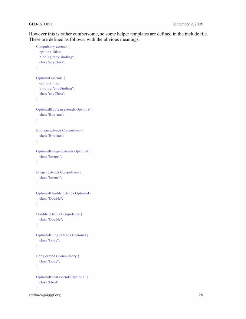
However this is rather cumbersome, so some helper templates are defined in the include file. These are defined as follows, with the obvious meanings.
Compulsory extends { optional false; binding "anyBinding"; class "anyClass"; } Optional extends { optional true; binding "anyBinding"; class "anyClass"; } OptionalBoolean extends Optional { class "Boolean"; } Boolean extends Compulsory { class "Boolean"; } OptionalInteger extends Optional { class "Integer"; } Integer extends Compulsory { class "Integer"; } OptionalDouble extends Optional { class "Double"; } Double extends Compulsory { class "Double"; } OptionalLong extends Optional { class "Long"; } Long extends Compulsory { class "Long"; } OptionalFloat extends Optional { class "Float"; }
GFD-R-D.051 September 9, 2005
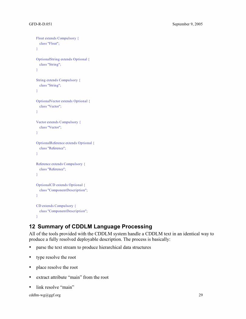
Float extends Compulsory { class "Float"; } OptionalString extends Optional { class "String"; } String extends Compulsory { class "String"; } OptionalVector extends Optional { class "Vector"; } Vector extends Compulsory { class "Vector"; } OptionalReference extends Optional { class "Reference"; } Reference extends Compulsory { class "Reference"; } OptionalCD extends Optional { class "ComponentDescription"; } CD extends Compulsory { class "ComponentDescription"; }
12 Summary of CDDLM Language Processing All of the tools provided with the CDDLM system handle a CDDLM text in an identical way to produce a fully resolved deployable description. The process is basically:
• parse the text stream to produce hierarchical data structures
• type resolve the root
• place resolve the root
• extract attribute “main” from the root
• link resolve “main”

GFD-R-D.051 September 9, 2005
• evaluate any functions in “main”
• check schemas in “main”
13 The CDDLM Syntax The complete CDDLM language syntax is presented here in its entirety.
Stream ::= AttributeList AttributeList ::= AttributeListElement* AttributeListElement ::= Attribute | #include STRING Attribute ::= Name Value Name ::= BaseReference // limited to WORD parts only Value ::= ; | Basic ; | Component | [LAZY] BaseReference ; Basic ::= NUMBER | STRING | MULTILINESTRING | Vector | BINARY Vector ::= [ ] | [ Basic (, Basic)* ] Component ::= extends [LAZY] BaseComponent BaseComponent ::= [Reference | NULL] ( ; | { AttributeList } ) BaseReference ::= ReferencePart (: ReferencePart)*
ReferencePart ::= ROOT | PARENT | WORD | THIS | ATTRIB WORD
14 The CDDLM Notation Lexical Rules In addition to the syntax, we need the rules for the language tokens.
/* White Space */ SKIP : " "| "\t"| "\n"| "\r"| "\f"

GFD-R-D.051 September 9, 2005
/* Comments */ SINGLELINECOMMENT: "//"~["\n"]"\n" FORMALCOMMENT: "/**" ~["*/"]"*/ " /* Reserved Tokens */ RESERVED: ";" | "," | "{" | "}" | "[" | "]" | ":" | true | false | "NULL" | "extends" | "LAZY" | "ROOT" | "ATTRIB" | "PROPERTY" | "IPROPERTY" | "PARENT" | "HOST" | "PROCESS" | "THIS" | "#include" /* Tokens – using Unicode */ WORD: LETTER (LETTER|DIGIT|SPECIAL)* SPECIAL: [".", "_", "-"] LETTER: [ "\u0024", "\u0041"-"\u005a", "\u005f", "\u0061"-"\u007a", "\u00c0"-"\u00d6", "\u00d8"-"\u00f6", "\u00f8"-"\u00ff", "\u0100"-"\u1fff", "\u3040"-"\u318f", "\u3300"-"\u337f", "\u3400"-"\u3d2d", "\u4e00"-"\u9fff", "\uf900"-"\ufaff" ] DIGIT: [ "\u0030"-"\u0039", "\u0660"-"\u0669", "\u06f0"-"\u06f9", "\u0966"-"\u096f", "\u09e6"-"\u09ef", "\u0a66"-"\u0a6f", "\u0ae6"-"\u0aef", "\u0b66"-"\u0b6f", "\u0be7"-"\u0bef", "\u0c66"-"\u0c6f", "\u0ce6"-"\u0cef", "\u0d66"-"\u0d6f", "\u0e50"-"\u0e59", "\u0ed0"-"\u0ed9", "\u1040"-"\u1049" ] /* Literals */

GFD-R-D.051 September 9, 2005
STRING: ("\"" ( (~["\"","\\","\n","\r"]) | ("\\" ( ["n","t","b","r","f","\\","'","\""] | ["0"-"3"] ["0"-"7"] ["0"-"7"] ) ) )* "\"") MULTILINESTRING: ("##" ( (~["#","\\"]) | ("\\" ( ["n","t","b","r","f","\\","'","#"] | ["0"-"3"] ["0"-"7"] ["0"-"7"] ) ) )* "#") NUMBER: <INTEGER> | <FLOAT> | <LONG> | <DOUBLE> | <BINARY> INTEGER: (("-")? ["1"-"9"] (["0"-"9"])*) | "0" FLOAT_BASE: ("-")? ( (["0"-"9"])+ "." (["0"-"9"])* (<EXPONENT>)? | "." (["0"-"9"])+ (<EXPONENT>)? | (["0"-"9"])+ <EXPONENT> | (["0"-"9"])+ (<EXPONENT>)? ) EXPONENT: ["e","E"] (["+","-"])? (["0"-"9"])+ > DOUBLE: <FLOAT_BASE> (["d", "D"])? LONG: <INTEGER> (["l", "L"])? FLOAT: <FLOAT_BASE> ["f", "F"] BINARY: "@" ["a"-"z","A"-"Z","0"-"9","+","/"]* "@" // note whitespace allowed and ignored
15 Encoding The text documents contain Unicode characters. The file representation is UTF-8, without a Byte Order Mark [6].

GFD-R-D.051 September 9, 2005
16 Security Considerations There are few security issues in the design of the language apart from the need to have a canonical representation of the text for signing. This canonical form is generated by the resolution processes.
17 Editor Information Patrick Goldsack Internet Systems and Storage Laboratory Hewlett-Packard Laboratories MailStop HPLB Filton Rd. Stoke Gifford Bristol BS34 8QZ United Kingdom Phone: +44 117 312 8176 Email: [email protected]
18 Contributors We gratefully acknowledge the contributions made to this specification by Marc Nijdam.
19 Acknowledgements This work was supported in part by Hewlett Packard Labs.
Intellectual Property Statement The GGF takes no position regarding the validity or scope of any intellectual property or other rights that might be claimed to pertain to the implementation or use of the technology described in this document or the extent to which any license under such rights might or might not be available; neither does it represent that it has made any effort to identify any such rights. Copies of claims of rights made available for publication and any assurances of licenses to be made available, or the result of an attempt made to obtain a general license or permission for the use of such proprietary rights by implementers or users of this specification can be obtained from the GGF Secretariat. The GGF invites any interested party to bring to its attention any copyrights, patents or patent applications, or other proprietary rights which may cover technology that may be required to practice this recommendation. Please address the information to the GGF Executive Director.
Full Copyright Notice Copyright (C) Global Grid Forum (2002, 2005). All Rights Reserved. This document and translations of it may be copied and furnished to others, and derivative works that comment on or otherwise explain it or assist in its implementation may be prepared, copied, published and distributed, in whole or in part, without restriction of any kind, provided that the above copyright notice and this paragraph are included on all such copies and derivative works. However, this document itself may not be modified in any way, such as by removing the copyright notice or references to the GGF or other organizations, except as needed for the

GFD-R-D.051 September 9, 2005
purpose of developing Grid Recommendations in which case the procedures for copyrights defined in the GGF Document process must be followed, or as required to translate it into languages other than English. The limited permissions granted above are perpetual and will not be revoked by the GGF or its successors or assigns. This document and the information contained herein is provided on an "AS IS" basis and THE GLOBAL GRID FORUM DISCLAIMS ALL WARRANTIES, EXPRESS OR IMPLIED, INCLUDING BUT NOT LIMITED TO ANY WARRANTY THAT THE USE OF THE INFORMATION HEREIN WILL NOT INFRINGE ANY RIGHTS OR ANY IMPLIED WARRANTIES OF MERCHANTABILITY OR FITNESS FOR A PARTICULAR PURPOSE."
References [1] SmartFrog reference manual
http://www.hpl.hp.com/research/smartfrog/papers/sfReference.pdf
[2] Configuration Description, Deployment, and Lifecycle Management (CDDLM) Foundation, http://forge.gridforum.org/projects/cddlm-wg/document/CDDLM_Foundation_Document/en/1
[3] Configuration Description, Deployment, and Lifecycle Management (CDDLM) XML-Based Language, Document in preparation
[4] Configuration Description, Deployment, and Lifecycle Management (CDDLM) Basic Services, Document in Preparation.
[5] RFC 3339, Date and Time on the Internet: Timestamps ftp://ftp.rfc-editor.org/in-notes/rfc3339.txt
[6] RFC 3629, UTF-8, a transformation format of ISO 10646 http://www.ietf.org/rfc/rfc3629.txt

GFD-R-D.051 September 9, 2005
20 An example deployment of a simple Grid application This example covers a small-scale application deployed onto a grid fabric.
The fact that this is deliberately small-scale is important; describing an application to be deployed on ten-thousand nodes is fundamentally different from describing one to deploy on ten nodes. The issues will be discussed in section 20.5. 20.1 Scenario: Tuple-space dispatch of stock analysis workload. The scenario covered here is the one of analysis of stock market data. The actual architecture somewhat from Van Simmons' paper Wall St., Grid Computing and Jini, which dispatches Monte-Carlo Simulation tasks to worker services deployed as Jini applications. Sun's JavaSpace Tuple-space is used to dispatch the tasks: tasks are described as documents inserted into the Tuple-space. Workers wait for documents of interest arriving in the space; when they arrive they can be pulled out and acted on –responses can be returned in the same way. This dispatch architecture is quite appealing, as it decouples service consumers from the services themselves; there is no need to know where a service is, only that there is something that acts on documents on certain topics in the space.
The paper also proposes an architecture for worker components; a container model similar to that for Web Servlets. A worklet runs inside the container, receives documents from "somewhere", processes them, and returns results. This architecture stops the worklets needing to know configuration data such as which JavaSpace/Topic to listen to, and permits a container to host multiple worklets, balance load between them, and do all the other nice things that Servlet containers are appreciated for.
This SmartFrog language example assumes the same architecture of container, worker and Tuple-space, but makes no assumptions about the technologies used to implement the T-Space. It could be Jini, it could be something built on top of WS-ResourceFramework and WS-Notification. Such details are not relevant to the deployment language. 20.2 Cross-application components First come some components that are specific to the technologies being used, but not to the application themselves. One would expect these to be predefined and includable into a system using the #include mechanism. 20.2.1 Java Processes First comes a Java process, which has some common options (here memory configuration), and a vector which allows arbitrary options to be listed (such as ["-ea","-server"]).
A schema is used to declare the type of these optional attributes, and a JavaProcess component is declared, one which uses the schema: 1 JavaProcessSchema extends Schema { 2 minMemory extends OptionalInteger; 3 maxMemory extends OptionalInteger; 4 JVM_options extends OptionalVector;
GFD-R-D.051 September 9, 2005
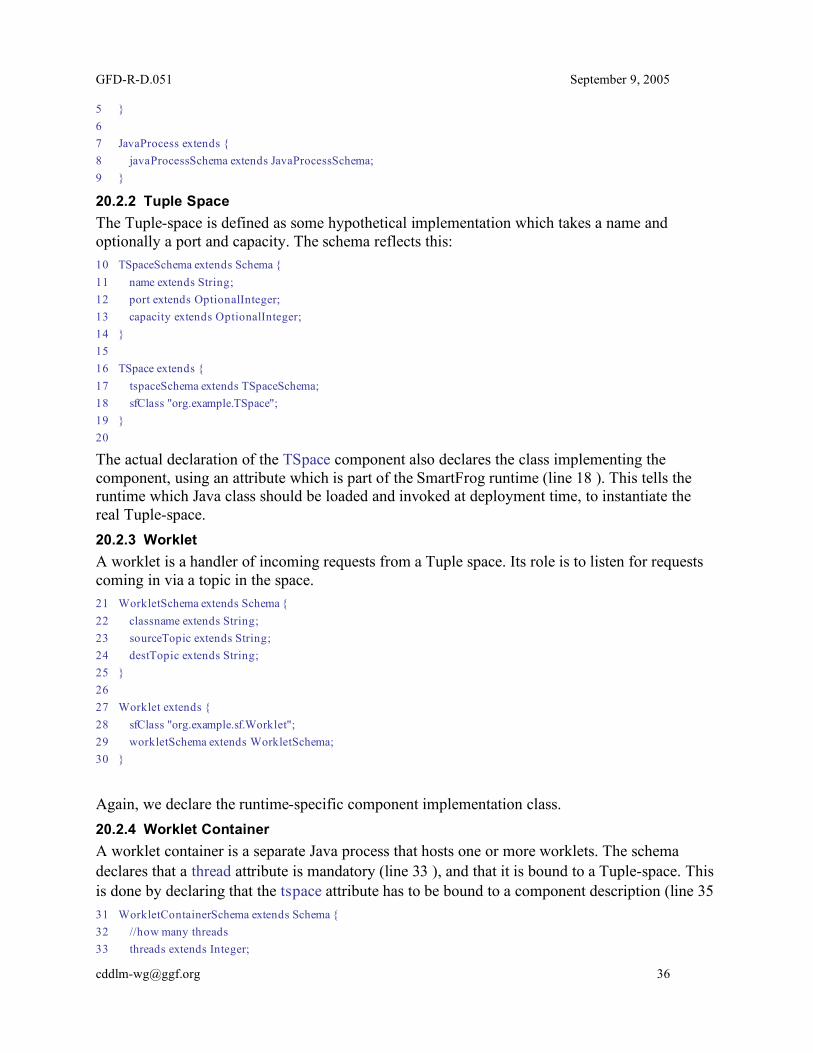
5 } 6 7 JavaProcess extends { 8 javaProcessSchema extends JavaProcessSchema; 9 }
20.2.2 Tuple Space The Tuple-space is defined as some hypothetical implementation which takes a name and optionally a port and capacity. The schema reflects this: 10 TSpaceSchema extends Schema { 11 name extends String; 12 port extends OptionalInteger; 13 capacity extends OptionalInteger; 14 } 15 16 TSpace extends { 17 tspaceSchema extends TSpaceSchema; 18 sfClass "org.example.TSpace"; 19 } 20
The actual declaration of the TSpace component also declares the class implementing the component, using an attribute which is part of the SmartFrog runtime (line 18 ). This tells the runtime which Java class should be loaded and invoked at deployment time, to instantiate the real Tuple-space. 20.2.3 Worklet A worklet is a handler of incoming requests from a Tuple space. Its role is to listen for requests coming in via a topic in the space. 21 WorkletSchema extends Schema { 22 classname extends String; 23 sourceTopic extends String; 24 destTopic extends String; 25 } 26 27 Worklet extends { 28 sfClass "org.example.sf.Worklet"; 29 workletSchema extends WorkletSchema; 30 }
Again, we declare the runtime-specific component implementation class. 20.2.4 Worklet Container A worklet container is a separate Java process that hosts one or more worklets. The schema declares that a thread attribute is mandatory (line 33 ), and that it is bound to a Tuple-space. This is done by declaring that the tspace attribute has to be bound to a component description (line 35 31 WorkletContainerSchema extends Schema { 32 //how many threads 33 threads extends Integer;
GFD-R-D.051 September 9, 2005
34 //what tuplespace is this container bound to 35 tspace extends CD; 36 }
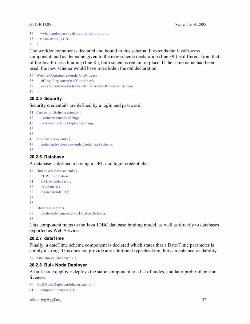
The worklet container is declared and bound to this schema. It extends the JavaProcess component, and as the name given to the new schema declaration (line 39 ) is different from that of the JavaProcess binding (line 8 ), both schemas remain in place. If the same name had been used, the new schema would have overridden the old declaration. 37 WorkletContainer extends JavaProcess { 38 sfClass "org.example.sf.Container"; 39 workletContainerSchema extends WorkletContainerSchema; 40 }
20.2.5 Security Security credentials are defined by a login and password. 41 CredentialsSchema extends { 42 username extends String; 43 password extends OptionalString; 44 } 45 46 Credentials extends { 47 credentialsSchema extends CredentialsSchema; 48 }
20.2.6 Database A database is defined a having a URL and login credentials: 49 DatabaseSchema extends { 50 //URL to database 51 URL extends String; 52 //credentials 53 login extends CD; 54 } 55 56 Database extends { 57 databaseSchema extends DatabaseSchema; 58 }
This component maps to the Java JDBC database binding model, as well as directly to databases exported as Web Services. 20.2.7 dateTime Finally, a dateTime schema component is declared which states that a Date/Time parameter is simply a string. This does not provide any additional typechecking, but can enhance readability. 59 dateTime extends String {}
20.2.8 Bulk Node Deployer A bulk node deployer deploys the same component to a list of nodes, and later probes them for liveness. 60 BulkNodeDeployerSchema extends { 61 component extends CD;

GFD-R-D.051 September 9, 2005
62 hosts extends Vector; 63 } 64 65 BulkNodeDeployer extends { 66 bulkNodeDeployerSchema extends BulkNodeDeployerSchema; 67 sfClass "org.example.sf.bulkNodeDeployer"; 68 }
20.3 Worklets Now the worklets are defined. In this example, we have multiple worklets, all using Tuple-space topics to communicate. 20.3.1 Past History Worklet The past history worklet looks at a stock over a period of time from a database and analyses it. It is configured by binding it to a database, a vector of stocks, and a start and end date. 69 PastHistoryAnalyzerSchema extends Schema { 70 database extends CD; 71 startDate extends dateTime; 72 endDate extends dateTime; 73 stock extends Vector; 74 } 75 76 PastHistoryAnalyzer extends Worklet { 77 classname "org.example.PHA"; 78 pastHistoryAnalyzerSchema extends PastHistoryAnalyzerSchema; 79 }
20.3.2 Predictor Worklet The predictor looks at the analyzed history and predicts future values for stocks 80 PredictorSchema extends Schema { 81 startDate extends dateTime; 82 endDate extends dateTime; 83 stock extends Vector; 84 } 85 86 PredictorWorklet extends Worklet { 87 classname "org.example.Predictor"; 88 predictorSchema extends PredictorSchema; 89 }
It will be deployed so that it listens on a topic for analyzed data coming from the PastHistory Worklets. 20.3.3 Data Feed Worklet A datafeed worklet takes external data and adds it to a Tuple-space. A declaration of an accessor class is mandatory; a cleaner class can sanitise the data; this is optional. 90 DataFeedSchema extends Schema { 91 URL extends String; 92 //credentials 93 login extends CD;

GFD-R-D.051 September 9, 2005
94 //classname of an accessor 95 accessor extends String; 96 //classname of an optional cleaner 97 cleaner extends OptionalString; 98 99 //tuple space information 100 tspace extends CD; 101 topic extends String; 102 } 103 104 DataFeed extends { 105 dataFeedSchema extends DataFeedSchema; 106 sfClass "org.example.sf.dataFeed"; 107 }
The datafeed will act as the source of data/events into the space. In a production system, the live feeds from various sources would be sanitized and validated before insertion into the space. For testing, valid past data (and wildly invalid data) would be used instead. 20.4 Test Data The test configuration runs a little database app internally when running, the property TestSourceDatabase:URL exports the URL to the database 108 TestSourceDatabase extends { 109 sfClass "org.example.sf.db.Test"; 110 location "/org/example/db/files"; 111 URL; 112 } 113
There is also a test Tuple-space 114 TestTSpace extends TSpace { 115 name "test-tspace"; 116 port 5600; 117 capacity 1000; 118 } 119
And a test login to the database: 120 TestCredentials extends Credentials { 121 username "guest"; 122 password "hello"; 123 } 124
20.5 Test Harness The test harness comprises a TestWorkletContainer and the Test application itself. 20.5.1 Test Worklet Container The test worklet container contains both types of worklet, and assumes that demand will keep the system busy as appropriate. 125 TestWorkletContainer extends WorkletContainer {
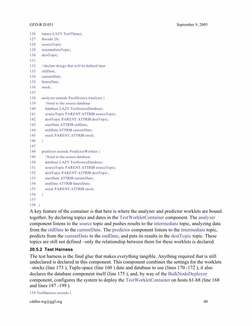
GFD-R-D.051 September 9, 2005
126 tspace LAZY TestTSpace; 127 threads 20; 128 sourceTopic; 129 intermediateTopic; 130 destTopic; 131 132 //declare things that will be defined later 133 oldDate; 134 currentDate; 135 futureDate; 136 stock; 137 138 analyzer extends PastHistoryAnalyzer { 139 //bind to the source database 140 database LAZY TestSourceDatabase; 141 sourceTopic PARENT:ATTRIB sourceTopic; 142 destTopic PARENT:ATTRIB destTopic; 143 startDate ATTRIB oldDate; 144 endDate ATTRIB currentDate; 145 stock PARENT:ATTRIB stock; 146 } 147 148 predictor extends PredictorWorklet { 149 //bind to the source database 150 database LAZY TestSourceDatabase; 151 sourceTopic PARENT:ATTRIB sourceTopic; 152 destTopic PARENT:ATTRIB destTopic; 153 startDate ATTRIB currentDate; 154 endDate ATTRIB futureDate; 155 stock PARENT:ATTRIB stock; 156 } 157 158 }
A key feature of the container is that here is where the analyzer and predictor worklets are bound together, by declaring topics and dates in the TestWorkletContainer component. The analyzer component listens to the source topic and pushes results to the intermediate topic, analyzing data from the oldDate to the currentDate. The predictor component listens to the intermediate topic, predicts from the currentDate to the endDate, and puts its results in the destTopic topic. These topics are still not defined –only the relationship between them for these worklets is declared. 20.5.2 Test Harness The test harness is the final glue that makes everything tangible. Anything required that is still undeclared is declared in this component. This component combines the settings for the worklets –stocks (line 173 ), Tuple-space (line 160 ) date and database to use (lines 170 -172 ), it also declares the database component itself (line 175 ), and, by way of the BulkNodeDeployer component, configures the system to deploy the TestWorkletContainer on hosts h1-h8 (line 168 and lines 187 -199 ). 159 TestHarness extends {
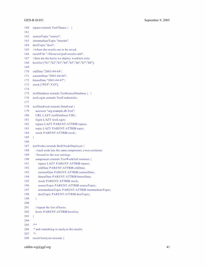
GFD-R-D.051 September 9, 2005
160 tspace extends TestTSpace { } 161 162 sourceTopic "source"; 163 intermediateTopic "interim"; 164 destTopic "dest"; 165 //where the results are to be saved. 166 resultFile "//fileserver/pub/results.xml"; 167 //here are the hosts we deploy worklets onto 168 hostlist ["h1","h2","h3","h4","h5","h6","h7","h8"]; 169 170 oldDate "2003-04-04"; 171 currentDate "2003-04-06"; 172 futureDate "2003-04-07"; 173 stock ["PEP","CO"]; 174 175 testDatabase extends TestSourceDatabase { } 176 testLogin extends TestCredentials; 177 178 testDataFeed extends DataFeed { 179 accessor "org.example.db.Test"; 180 URL LAZY testDatabase:URL; 181 login LAZY testLogin; 182 tspace LAZY PARENT:ATTRIB tspace; 183 topic LAZY PARENT:ATTRIB topic; 184 stock PARENT:ATTRIB stock; 185 } 186 187 testNodes extends BulkNodeDeployer { 188 //each node has the same component, a test container 189 //bound to the test settings 190 component extends TestWorkletContainer { 191 tspace LAZY PARENT:ATTRIB tspace; 192 oldDate PARENT:ATTRIB oldDate; 193 currentDate PARENT:ATTRIB currentDate; 194 futureDate PARENT:ATTRIB futureDate; 195 stock PARENT:ATTRIB stock; 196 sourceTopic PARENT:ATTRIB sourceTopic; 197 intermediateTopic PARENT:ATTRIB intermediateTopic; 198 destTopic PARENT:ATTRIB destTopic; 199 } 200 201 //repeat the list of hosts. 202 hosts PARENT:ATTRIB hostlist; 203 } 204 205 /** 206 * and something to analyze the results 207 */ 208 resultAnalyzer extends {

GFD-R-D.051 September 9, 2005
209 sfClass "org.example.sf.ResultAnalyzer"; 210 tspace LAZY PARENT:ATTRIB tspace; 211 topic PARENT:ATTRIB destTopic; 212 resultFile PARENT:ATTRIB resultFile; 213 } 214 }
Finally, a new component is declared, a resultAnalyzer, which somehow analyzes the test results and compares them to expected values. This could perhaps itself be written as a worklet and hosted in a separate WorkletContainer instance. This is quite a complex declaration. It combines configuration of individual components, with the configuration of the entire distributed system. Because a single component can do both, different configurations could be created to test different aspects of the system, such as different data sources, or different distribution options.
Note that when binding attributes to instances of components, the LAZY keyword is used. This is because the binding can not take place until deployment actually occurs. The LAZY keyword is also used to access other information that is only available at runtime, such as the URL of the database (line 180 ). Although it may not seem immediately intuitive as to what attribute bindings should be marked as LAZY, the parser will inform the user during the resolution phase if it was unable to resolve all references. Parsing of the deployment descriptor can therefore identify issues long before deployment is attempted. 20.6 Liveness Liveness is not explicitly covered in this example. It is assumed that every application or worklet has a means by which liveness can be probed, and therefore which implementation classes of the declared SmartFrog components can use to probe the application when requested to do so by their parent components. For a production system, rigorous checks which actually make database queries, or submit work to the worklets could be considered, provided the execution costs and potential side-effects are acceptable. 20.7 Scaling As mentioned at the introduction, a ten-thousand node application deploys differently. Here are some underlying issues:
• You can not expect all the nodes to be available at the same time. You do not want to redeploy the application whenever a node appears or disappears, nor can you have one single descriptor to describe the entire system.
• You do not want to sequentially deploy parts of an application to all the nodes; it would take too long.
• The number of processing elements can be changed based on system load.
The way to address these problems is to not adopt such an explicit top-down description of the configuration. Instead the system should be viewed as functional when there are an acceptable number of worklets processing data. The deployment descriptor should not itself list all the hosts in the grid fabric onto which system components should be deployed. Instead, the descriptor should describe which system components are to be deployed onto hosts in particular roles.

GFD-R-D.051 September 9, 2005
When the Grid Resource Manager allocates a new node to the application, it must be given a role, and it must then communicate with some service to discover what application it should deploy, given its role. Such dynamic role-based deployment is possible, given the appropriate components.