configuration guide - ftp.bircom.comftp.bircom.com/audiocodes/mediant_500l/docs/ltrt... · this...
TRANSCRIPT

Configuration Guide Configuring MSBR for LAN & WAN Access
using CLI
Version 6.8
Multi-Service Business Routers (MSBR) Access, Data, Voice & Security
Session Border Controller (SBC)

Version 6.8 3 Mediant MSBR
Configuration Guide Contents
Table of Contents 1 Introduction ......................................................................................................... 7
2 Cellular Interfaces (3G vs. 4G) ........................................................................... 9
2.1 Examples ............................................................................................................... 10
3 PPP and PPPoE ................................................................................................. 13
3.1 Examples ............................................................................................................... 14
4 ADSL .................................................................................................................. 15
4.1 Examples ............................................................................................................... 15
5 VDSL ................................................................................................................... 17
5.1 Examples ............................................................................................................... 17
6 ADSL/VDSL Recovery ....................................................................................... 19
6.1 Examples ............................................................................................................... 19
7 ATM-based Interfaces and Encapsulation ...................................................... 21
7.1 Examples ............................................................................................................... 22
8 EFM Interfaces ................................................................................................... 25
8.1 Examples ............................................................................................................... 25
9 SHDSL - EFM/ATM ............................................................................................. 27
9.1 Examples ............................................................................................................... 28
10 Multiple DSL Connection .................................................................................. 31
10.1 Examples ............................................................................................................... 31
11 E1/T1 (PRI) ......................................................................................................... 33
11.1 Examples ............................................................................................................... 34
12 Serial HDLC ....................................................................................................... 35
12.1 Examples ............................................................................................................... 35
13 Fiber Optic ......................................................................................................... 37
13.1 Examples ............................................................................................................... 37
14 WAN Failover ..................................................................................................... 39
14.1 Examples ............................................................................................................... 40 14.1.1 Cold Backup WAN Failover ..................................................................................... 40 14.1.2 Hot Backup WAN Failover ....................................................................................... 41
15 Wi-Fi ................................................................................................................... 43
15.1 Examples ............................................................................................................... 46 15.2 Advanced Wi-Fi Example ....................................................................................... 48
16 LLDP ................................................................................................................... 51
16.1 Examples ............................................................................................................... 51

Access 4 Document #: LTRT-31662
LAN & WAN Access Interfaces
This page is intentionally left blank.

Version 6.8 5 Mediant MSBR
Configuration Guide Notices
Notice This document describes access configuration using the CLI management interface for AudioCodes Multi-Service Business Routers (MSBR). Information contained in this document is believed to be accurate and reliable at the time of printing. However, due to ongoing product improvements and revisions, AudioCodes cannot guarantee accuracy of printed material after the Date Published nor can it accept responsibility for errors or omissions. Before consulting this document, check the corresponding Release Notes regarding feature preconditions and/or specific support in this release. In cases where there are discrepancies between this document and the Release Notes, the information in the Release Notes supersedes that in this document. Updates to this document and other documents as well as software files can be downloaded by registered customers at http://www.audiocodes.com/downloads.
© Copyright 2016 AudioCodes Ltd. All rights reserved. This document is subject to change without notice.
Date Published: June-15-2016
Trademarks AudioCodes, AC, HD VoIP, HD VoIP Sounds Better, IPmedia, Mediant, MediaPack, What’s Inside Matters, OSN, SmartTAP, VMAS, VoIPerfect, VoIPerfectHD, Your Gateway To VoIP, 3GX, VocaNOM and CloudBond 365 are trademarks or registered trademarks of AudioCodes Limited All other products or trademarks are property of their respective owners. Product specifications are subject to change without notice.
WEEE EU Directive Pursuant to the WEEE EU Directive, electronic and electrical waste must not be disposed of with unsorted waste. Please contact your local recycling authority for disposal of this product.
Customer Support Customer technical support and services are provided by AudioCodes or by an authorized AudioCodes Service Partner. For more information on how to buy technical support for AudioCodes products and for contact information, please visit our Web site at www.audiocodes.com/support.
Abbreviations and Terminology Each abbreviation, unless widely used, is spelled out in full when first used.
Access 6 Document #: LTRT-31662
LAN & WAN Access Interfaces
Document Revision Record
LTRT Description
31660 Initial document release for Version 6.8.
31661 A/VDSL recovery added.
Documentation Feedback AudioCodes continually strives to produce high quality documentation. If you have any comments (suggestions or errors) regarding this document, please fill out the Documentation Feedback form on our Web site at http://www.audiocodes.com/downloads.

Version 6.8 7 Mediant MSBR
Configuration Guide 1. Introduction
1 Introduction This document describes the different types of LAN and WAN access interfaces and protocols supported by the MSBR. It provides a description of the commands necessary to configure the type of access as well as typical configuration examples.

Access 8 Document #: LTRT-31662
LAN & WAN Access Interfaces
This page is intentionally left blank.

Version 6.8 9 Mediant MSBR
Configuration Guide 2. Cellular Interfaces (3G vs. 4G)
2 Cellular Interfaces (3G vs. 4G) 3G is the third generation of mobile telecommunications technology. This is based on a set of standards used for mobile devices and mobile telecommunication services. 3G telecommunication networks support services that provide an information transfer rate of at least 200 Kbit/s. The 3G versions 3.5G and 3.75G also provide mobile broadband access of several Mbit/s to smartphones and mobile modems in laptop computers. 4G is the fourth generation of mobile telecommunications technology succeeding 3G. A 4G system, in addition to usual voice and other services of 3G system, provides mobile ultra-broadband Internet access, for example to laptops with USB wireless modems, to smartphones, and to other mobile devices. Two 4G candidate systems are commercially deployed: the Mobile WiMAX standard and the first-release Long Term Evolution (LTE) standard. 4G technologies enable IP-based voice, data and streaming multimedia at higher speeds and offer at least 100 Mbit/s with high mobility and up to 1 GBit/s with low mobility.
Command Description
# configure data Enter data configuration menu.
(config-data)# interface Cellular slot/port
Enter the cellular interface configuration commands. Type interface cellular ? to display slot/port location on MSBR.
(conf-cellular)# pin [pin number] Personal identification number. This is a numeric password shared between a user and a system for authentication. The command pin grants access only when the number is correct.
(conf-cellular)# ppp [user] pass/obscured-pass [password]
Cellular interface can be configured to use PPP authentication protocol when required.
(conf-cellular)# apn [AccessPoint_Name]
Configures the name of the Gateway between 3G/4G mobile network and another computer network (internet). A mobile device making a data connection must be configured with an APN to present to the carrier. The carrier then examines this identifier to determine what type of network connection should be created, for example: what IP addresses should be assigned to the wireless device, what security methods should be used, and how or if, it should be connected to some private customer network.
(conf-cellular)# initstr [AT-Style]
The command set consists of a series of short text strings which combine together to produce complete commands for operations such as dialing, hanging up, and changing the parameters of the connection.

Access 10 Document #: LTRT-31662
LAN & WAN Access Interfaces
2.1 Examples When you attach the cellular modem to MSBR, the MSBR immediately installs drivers.
Figure 2-1: Cellular Interface Example
Looking for target devices ... No devices in target mode or class found Looking for default devices ... Found devices in default mode or class (1) Accessing device 005 on bus 001 ...[4361336.011000] usb 1-1.2: usbfs: process 7445 (usb_modeswitch) did not claim interface 0 before use Getting the current device configuration ... OK, got current device configuration (1) Using endpoints 0x01 (out) and 0x81 (in) Using endpoints 0x01 (out) and 0x81 (in) Inquiring device details; driver will be detached ... Looking for active driver ... OK, driver found ("usb-storage") OK, driver "usb-storage" detached SCSI inquiry data (for identification) ------------------------- Vendor String: HUAWEI Model String: Mass Storage Revision String: 2.31 ------------------------- USB description data (for identification) ------------------------- Manufacturer: Huawei Technologies Product: HUAWEI Mobile Serial No.: not provided ------------------------- Setting up communication with interface 0 ... Using endpoint 0x01 for message sending ... Trying to send message 1 to endpoint 0x01 ... OK, message successfully sent Resetting response endpoint 0x81 Resetting message endpoint 0x01 Checking for mode switch (max. 20 times, once per second) ...
USB 3GCellular Modem
MSBR

Version 6.8 11 Mediant MSBR
Configuration Guide 2. Cellular Interfaces (3G vs. 4G)
Waiting for original device to vanish ... Original device can't be accessed anymore. Good. Searching for target devices ... Searching for target devices ... Searching for target devices ... Searching for target devices ... Searching for target devices ... Found target device, now opening Found correct target device Mode switch succeeded. Bye. After MSBR successfully installs the driver, it configures the cellular interface (but not completely): #configure data (config-data)# interface Cellular 0/0
Configured automatically: (conf-cellular)# ip dns server auto (conf-cellular)# initstr AT&F (means Restore factory settings) (conf-cellular)# apn uinternet (conf-cellular)# phone *99# (conf-cellular)# firewall enable (conf-cellular)# napt (conf-cellular)# mtu auto (conf-cellular)# ip address auto
Configured manually: (conf-cellular)# ppp user orange pass PASSWORD (conf-cellular)# no shutdown (conf-cellular)# pin 1111 (without this command there will be no connection to the internet) (conf-cellular)# exit # Add Default route to traffic through Cellular interface: (config-data)# ip route 0.0.0.0 0.0.0.0 Cellular 0/0
The following show command displays the current status of the interface: # show data interfaces cellular 0/0 Cellular 0/0 is Connected. Description: 3G Cellular PPP connection IP address negotiated using PPP is 10.170.120.150 State Time: 0:01:19 Time since creation: 0:02:25 Time since last counters clear : 0:01:19 mtu auto napt network wan DNS is configured dynamic DNS primary IP address is 82.102.139.10

Access 12 Document #: LTRT-31662
LAN & WAN Access Interfaces
DNS secondary IP address is 82.102.139.20 IPv6 is disabled rx_packets 13 rx_bytes 594 rx_dropped 0 rx_errors 0 tx_packets 13 tx_bytes 416 tx_dropped 0 tx_errors 0 15-seconds input rate: 22 bits/sec, 0 packets/sec 15-seconds output rate: 16 bits/sec, 0 packets/sec Tunnel destination server is (none) Remote server IP: 10.64.64.64 ppp configuration: username: orange, password: (not shown) enabled authentication methods: chap ms-chap ms-chap-v2 pap lcp echo parameters: interval 6, fails
The following show command displays all the cellular interface status: # show data cellular status Cellular interface status: Modem status: UP PPP status: UP KB sent: 708 KB received: 631 Packets sent: 42503 Packets received: 42831
Verify that the cellular installation has completed successfully, using the following command: # show system assembly Board Assembly Info: | Slot No. | Ports | Module Type | | 0/0 | 1 | WAN-Copper | | 0/1 | 1 | WAN-Fiber | | 0/2 | 1 | WAN-A/VDSL | | 1 | 1-4 | LAN-GE | | 2 | 1-4 | FXS | USB Port 1: Manufacturer - ZTE,Incorporated, Product - ZTE WCDMA Technologies MSM, Product Id - 0124, Vendor Id - 19d2, Type - Cellular USB Port 2: Empty
You can also use the cellular interface for WAN backup, as described in Section 14 on page 39.

Version 6.8 13 Mediant MSBR
Configuration Guide 3. PPP and PPPoE
3 PPP and PPPoE Point-to-Point Protocol (PPP) and Point-to-Point Protocol over Ethernet (PPPoE) are network protocols that allow data communication between two network hosts or points. PPPoE is encapsulated in Ethernet frames. Both protocols exist at the network access layer (also known as the data link layer). PPP can be encapsulated in a number of data link layer protocols such as Ethernet (PPPoE). PPP supports three types of user authentication protocols that provide varying levels of security (CHAP/PAP/EAP). PPPoE expands the original capability of PPP by allowing a virtual point-to-point connection over a multipoint Ethernet network architecture, PPPoE is configured as a point-to-point connection between two Ethernet ports. As a tunneling protocol, PPPoE is used as an effective foundation for the transport of IP packets at the network layer.
Command Description
# configure data Enter data configuration menu.
(config-data)# interface pppoe [0-7 interface number]
Enter the PPPoE interface commands.
(conf-pppoe-[number])# underlying [interface slot/port]
Configures the interface with which the PPPoE interface commands are associated.
(conf-pppoe-[number])# ppp user[user name] obscured-pass [pass]
Configures the user and password authentication by using PPP on that interface.
(conf-pppoe-[number])# ppp authentication [chap/pap/ms-chap/ms-chap-v2]
Enables PPP authentication. No limit is placed on which and how many authentication is used (all four can be activated on the same interface). pap: Password Authentication Protocol –
normal login when a connection has been made the host sends a username and password.
chap: Challenge Handshake Authentication Protocol – CHAP does not have these deficiencies. With CHAP, the authenticator (i.e. the server) sends a randomly generated ``challenge'' string to the client, along with its hostname. The client uses the hostname to look up the appropriate secret, combines it with the challenge, and encrypts the string using a one-way hashing function. The result is returned to the server along with the client's hostname.
ms-chap: Microsoft version of CHAP authentication.
(conf-pppoe-[number])# ppp lcp-echo [interval_sec_number] [fails number]
PPP Link Control Protocol (LCP) negotiates the link and PPP parameters to dynamically configure the data link layer of a PPP connection. Interval option: determines how often Echo-
Request messages are sent on idle links to check the viability and integrity of the link.
Fails option: determines how many echo-reply missed before announcing that the link has been broken.

Access 14 Document #: LTRT-31662
LAN & WAN Access Interfaces
3.1 Examples This example shows how to use PPP authentication after plugging in the cellular modem device. You need to enter a username and encrypted password to make the cellular modem authenticate with the server.
Figure 3-1: PPP and PPPoE Example
# configure data MSBR(config-data)# int cellular 0/0 MSBR(conf-cellular)# ppp user user pass 012@pass
Another example is after a VDSL connection has been established, an EFM interface is automatically configured, but you need to configure the PPPoE interface: #configure data (config-data)# interface EFM 0/2 (conf-if-efm 0/2)# ip address 10.3.90.26 255.255.0.0 (conf-if-efm 0/2)# desc "VDSL" (conf-if-efm 0/2)# no shutdown (conf-if-efm 0/2)# exit (config-data)#int pppoe 0 (conf-pppoe-0)# ppp user user@ISP pass PASSWORD (conf-pppoe-0)# ppp authentication chap (conf-pppoe-0)# ppp authentication ms-chap (conf-pppoe-0)# ppp authentication ms-chap-v2 (conf-pppoe-0)# ppp authentication pap (conf-pppoe-0)# ppp lcp-echo 6 5 (conf-pppoe-0)# underlying EFM 0/2 (conf-pppoe-0)# no shutdown (conf-pppoe-0)# exit (config-data)# ip route 0.0.0.0 0.0.0.0 EFM 0/2
USB 3GCellular Modem
MSBR

Version 6.8 15 Mediant MSBR
Configuration Guide 4. ADSL
4 ADSL Asymmetric Digital Subscriber Line (ADSL) is a technology for transmitting digital information at a high bandwidth on existing phone lines to homes and businesses. ADSL is asymmetric in that it uses most of the channel to transmit downstream to the user and only a small part to receive information from the user. ADSL is generally offered at downstream data rates from 512 Kbps to about 6 Mbps. It uses standard telephone lines to upload and download data on a digital frequency, which sets these data streams apart from the analog signals that telephones and fax machines use. The telephone can be used at the same time when surfing the Web with DSL service because the signal is operating on a different frequency. To configure ADSL mode use this commands:
Command Description
# configure data Enter data configuration menu.
(config-data)# interface dsl slot/port
Enter the physical DSL port.
(conf-if-dsl slot/port)# mode[adsl/vdsl]
Configure the mode on the DSL port.
(conf-if-dsl slot/port)# no shutdown
Shutdown is default configuration for this kind of port; use it to enable the DSL interface.
# show data interfaces dsl slot/port
Displays DSL interface information such as: current configuration, downstream and upstream bandwidth and status (connected, disconnected).
4.1 Examples In this example, MSBR connects to the Internet Service Provider and configures it to ADSL mode.
Figure 4-1: ADSL Example
# configure data (config-data)# interface dsl 0/0 (conf-if-dsl 0/0)# no shutdown (conf-if-dsl 0/0)# mode adsl
ADSL connection
DSL 0/0
MSBR
Service Provider
MPLSInternet Network
MPLSLAN
Client 1

Access 16 Document #: LTRT-31662
LAN & WAN Access Interfaces
Once the DSL port has been configured to connect to ADSL, the show command displays the status of the interface: # show data interfaces dsl 0/2 Hardware is ADSL/VDSL-WAN mezzanine, rev 1 on slot 0/2 Capabilities: CPE termination. ADSL Annex A/J, VDSL2 Framer XWAY VRX268 Firmware ver 1.5 DSL Link Info Configuration: mode adsl, no shutdown Line Termination: CPE, Annex: A DSL mode: ADSL2+ (ITU-T G.992.5) Status: Connected Downstream info Data rate (bps): Maximum Attainable 26488000/ Actual 26488000 Power 10.2, Line Attenuation 0.0, SNR Margin 10.6 Upstream info Data rate (bps): Maximum Attainable 1239000/ Actual 1236000 Power 12.4, Line Attenuation 0.0, SNR Margin 6.0 Performance Monitoring Current 15-min interval statistics (Assessed seconds: 67): NearEnd - UAS: [ 39], ES: [ 0], SES: [ 0], LOSS: [ 0], LOFS: [ 0], CRC: [ 0], FEC: [ 0], HEC: [ 0] FarEnd - UAS: [ 39], ES: [ 0], SES: [ 0], LOSS: [ 0], LOFS: [ 0], CRC: [ 0], FEC: [ 0], HEC: [ 0] ATM Rx 37401 cells 181 data cells Last 24-hour interval statistics: (Assessed seconds: 67) NearEnd - UAS: [ 39], ES: [ 0], SES: [ 0], LOSS: [ 0], LOFS: [ 0], CRC: [ 0], FEC: [ 0], HEC: [ 0] FarEnd - UAS: [ 39], ES: [ 0], SES: [ 0], LOSS: [ 0], LOFS: [ 0], CRC: [ 0], FEC: [ 0], HEC: [ 0] ATM Rx 37401 cells 181 data cells Last showtime statistics: (Assessed seconds: 13) NearEnd - UAS: [ 0], ES: [ 0], SES: [ 0], LOSS: [ 0], LOFS: [ 0], CRC: [ 0], FEC: [ 0], HEC: [ 0] FarEnd - UAS: [ 39], ES: [ 0], SES: [ 0], LOSS: [ 0], LOFS: [ 0], CRC: [ 0], FEC: [ 0], HEC: [ 0] ATM Rx 37401 cells 181 data cells
DSL. Current bandplan table Band Format: (Index, Direction,(First Tone Idx, Last Tone Idx),(First Tone MHz, Last Tone MHz)) ( 0, DOWNSTREAM, ( 32, 511), ( 0.138, 2.204)) ( 1, UPSTREAM, ( 6, 31), ( 0.026, 0.134))

Version 6.8 17 Mediant MSBR
Configuration Guide 5. VDSL
5 VDSL Very-high-bit-rate digital subscriber line (VDSL or VHDSL) is a digital subscriber line (DSL) technology providing data transmission faster than ADSL over a single flat untwisted or twisted pair of copper wires (up to 52 Mbit/s downstream and 12 Mbit/s upstream), using the frequency band from 25 kHz to 12 MHz. These rates mean that VDSL is capable of supporting applications such as high-definition television, as well as telephone services (voice over IP) and general Internet access, over a single connection.
Command Description
# configure data Enter data configuration menu.
(config-data)# interface dsl slot/port
Enter the physical DSL port.
(conf-if-dsl slot/port)# mode[adsl/vdsl]
Configure the mode on the DSL port.
(conf-if-dsl slot/port)# no shutdown
Shutdown is default configuration for this kind of port; use it to enable the DSL interface.
# show data interfaces dsl slot/port
Displays DSL interface information such as: current configuration, downstream and upstream bandwidth and status (connected, disconnect).
5.1 Examples In this example, MSBR is connected to the Service Provider and is configured to VDSL mode.
Figure 5-1: VDSL Example
# configure data (config-data)# interface dsl 0/0 (conf-if-dsl 0/0)# no shutdown (conf-if-dsl 0/0)# mode vdsl
After you have configured the DSL port connection to VDSL, use the following command to display the status of the interface: # show data interfaces dsl Hardware is ADSL/VDSL-WAN mezzanine, rev 1 on slot 0/0 Capabilities: CPE termination. ADSL Annex A/J, VDSL2 Framer XWAY VRX268 Firmware ver 1.5 DSL Link Info Configuration: mode vdsl, no shutdown Line Termination: CPE, Annex: A DSL mode: VDSL2 (ITU-T G.993.1), VDSL Profile DSL_PROFILE_17A Status: Connected
VDSL connection
DSL 0/2
Service Provider
MPLSInternet Network
MPLSLAN
Client 1

Access 18 Document #: LTRT-31662
LAN & WAN Access Interfaces
Downstream info Data rate (bps): Maximum Attainable 141622672/ Actual 119992000 Power 6.6, Line Attenuation 0.4, SNR Margin 12.5 Upstream info Data rate (bps): Maximum Attainable 60740000/ Actual 50008000 Power 10.7, Line Attenuation 0.0, SNR Margin 13.7 Performance Monitoring Current 15-min interval statistics (Assessed seconds: 90): NearEnd - UAS: [ 35], ES: [ 0], SES: [ 0], LOSS: [ 0], LOFS: [0], CRC: [ 0], FEC: [ 0], HEC: [ 0] FarEnd - UAS: [ 35], ES: [ 0], SES: [ 0], LOSS: [ 0], LOFS: [0], CRC: [ 0], FEC: [ 0], HEC: [ 0] Last 24-hour interval statistics: (Assessed seconds: 90) NearEnd - UAS: [ 35], ES: [ 0], SES: [ 0], LOSS: [ 0], LOFS: [0], CRC: [ 0], FEC: [ 0], HEC: [ 0] FarEnd - UAS: [ 35], ES: [ 0], SES: [ 0], LOSS: [ 0], LOFS: [0], CRC: [ 0], FEC: [ 0], HEC: [ 0] Last showtime statistics: (Assessed seconds: 39) NearEnd - UAS: [ 0], ES: [ 0], SES: [ 0], LOSS: [ 0], LOFS: [0], CRC: [ 0], FEC: [ 0], HEC: [ 0] FarEnd - UAS: [ 35], ES: [ 0], SES: [ 0], LOSS: [ 0], LOFS: [0], CRC: [ 0], FEC: [ 0], HEC: [ 0]
DSL. Current bandplan table Band Format: (Index, Direction,(First Tone Idx, Last Tone Idx),(First Tone MHz, Last Tone MHz)) ( 0, DOWNSTREAM, ( 161, 857), ( 0.694, 3.696)) ( 1, DOWNSTREAM, ( 1218, 1959), ( 5.253, 8.448)) ( 2, DOWNSTREAM, ( 2795, 4083), ( 12.053, 17.608)) ( 3, UPSTREAM, ( 882, 1193), ( 3.804, 5.145)) ( 4, UPSTREAM, ( 1984, 2770), ( 8.556, 11.946))
Version 6.8 19 Mediant MSBR
Configuration Guide 6. ADSL/VDSL Recovery
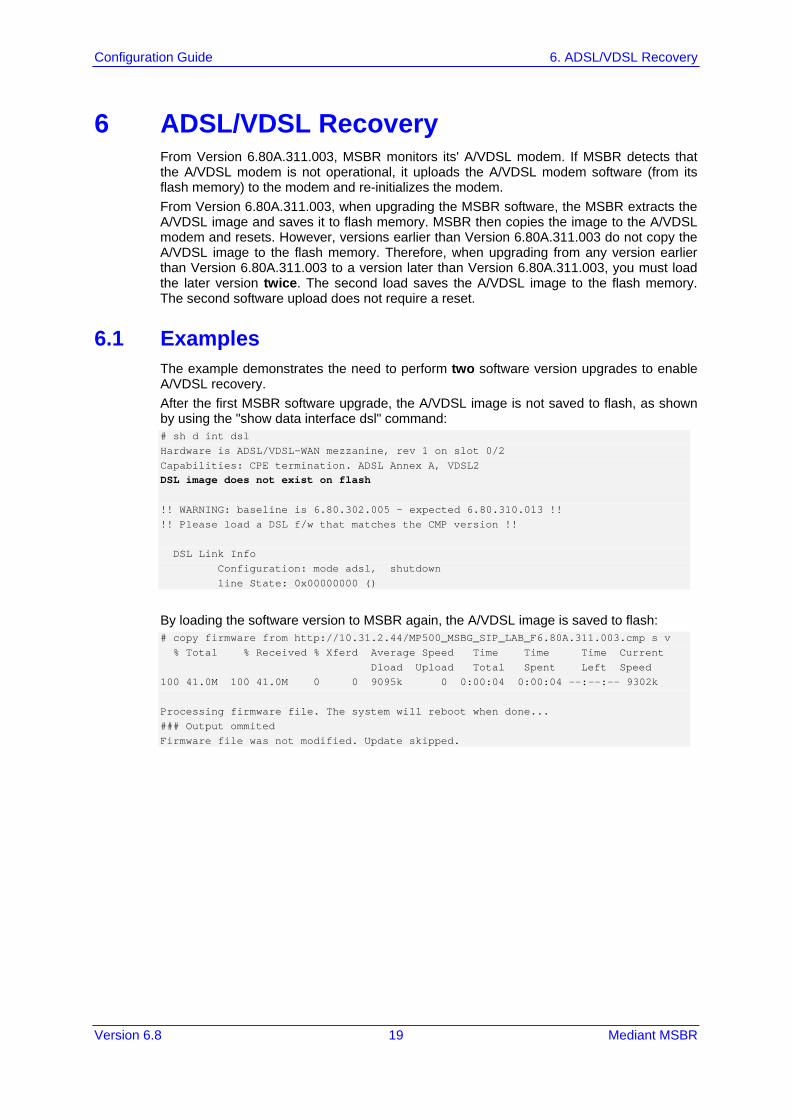
6 ADSL/VDSL Recovery From Version 6.80A.311.003, MSBR monitors its' A/VDSL modem. If MSBR detects that the A/VDSL modem is not operational, it uploads the A/VDSL modem software (from its flash memory) to the modem and re-initializes the modem. From Version 6.80A.311.003, when upgrading the MSBR software, the MSBR extracts the A/VDSL image and saves it to flash memory. MSBR then copies the image to the A/VDSL modem and resets. However, versions earlier than Version 6.80A.311.003 do not copy the A/VDSL image to the flash memory. Therefore, when upgrading from any version earlier than Version 6.80A.311.003 to a version later than Version 6.80A.311.003, you must load the later version twice. The second load saves the A/VDSL image to the flash memory. The second software upload does not require a reset.
6.1 Examples The example demonstrates the need to perform two software version upgrades to enable A/VDSL recovery. After the first MSBR software upgrade, the A/VDSL image is not saved to flash, as shown by using the "show data interface dsl" command: # sh d int dsl Hardware is ADSL/VDSL-WAN mezzanine, rev 1 on slot 0/2 Capabilities: CPE termination. ADSL Annex A, VDSL2 DSL image does not exist on flash !! WARNING: baseline is 6.80.302.005 - expected 6.80.310.013 !! !! Please load a DSL f/w that matches the CMP version !! DSL Link Info Configuration: mode adsl, shutdown line State: 0x00000000 ()
By loading the software version to MSBR again, the A/VDSL image is saved to flash: # copy firmware from http://10.31.2.44/MP500_MSBG_SIP_LAB_F6.80A.311.003.cmp s v % Total % Received % Xferd Average Speed Time Time Time Current Dload Upload Total Spent Left Speed 100 41.0M 100 41.0M 0 0 9095k 0 0:00:04 0:00:04 --:--:-- 9302k Processing firmware file. The system will reboot when done... ### Output ommited Firmware file was not modified. Update skipped.

Access 20 Document #: LTRT-31662
LAN & WAN Access Interfaces
The "show data interface dsl" command shows that the A/VDSL image is saved to flash: # sh d int dsl Hardware is ADSL/VDSL-WAN mezzanine, rev 1 on slot 0/2 Capabilities: CPE termination. ADSL Annex A, VDSL2 Framer XWAY VRX268 Firmware ver 1.5 Driver Ver 4.16.6 Driver MEI BSP Ver 1.4.9 ChipSet FW Ver 5.7.3.15.0.1 DSL image saved to flash. version is: 6.80.310.013 DSL Link Info Configuration: mode adsl, shutdown line State: 0x00000200 (Silent)

Version 6.8 21 Mediant MSBR
Configuration Guide 7. ATM-based Interfaces and Encapsulation
7 ATM-based Interfaces and Encapsulation Asynchronous Transfer Mode (ATM) is a high-speed networking standard designed to support both voice and data communications. ATM is normally utilized by Internet service providers on their private long-distance networks. ATM operates at the data link layer (Layer 2 in the OSI model) over either fiber or twisted-pair cable. ATM differs from more common data link technologies such as Ethernet in several ways: ATM utilizes no routing. Hardware devices known as ATM switches establish point-to-
point connections between endpoints and data flows directly from source to destination.
Instead of using variable-length packets as Ethernet does, ATM utilizes fixed-sized cells. ATM cells are 53 bytes in length that includes 48 bytes of data and 5 bytes of header information.
ATM technology is designed to improve utilization and quality of service (QoS) on high-traffic networks. Without routing and with fixed-size cells, networks can much more easily manage bandwidth under ATM than under Ethernet.
Command Description
# configure data Enter data configuration menu.
(config-data)# interface atm slot/port
Create a logical ATM port that "rides" on the DSL physical port.
(conf-atm slot/port)# pvc slot/number_pvc
Establishes a permanent virtual circuit (PVC) connection. Specify the PVC number as well.
(conf-atm slot/port)# ubr Unspecified bit rate, a traffic contract used to guarantee QoS for ATM networks.
(conf-atm slot/port)# ip address [IP Address] [Subnet Mask]
Configure an IP Version 4 address for the ATM interface.
(conf-atm slot/port)# encapsulation [ethoa-mux ,ethoa-snap, ipoa-mux ,ipoa-snap ,pppoa-mux , pppoa-snap,pppoe , pppoe-mux]
Configure the protocol type: ipoa: IP over ATM ethoa: Ethernet over ATM pppoe: PPP over Ethernet pppoa: PPP over ATM Configure the encapsulation: snap: SubNetwork Attachment Point (SNAP).
This is an encapsulation called LLC. LLC encapsulation is needed when more than one protocol might be carried over the same VC (Virtual Circuit) and the snap header uniquely identifies a routed or bridged protocol. For example, value 0x00-00-00 indicates that an EtherType is in use.
mux: Multiplexing. In the "VC Multiplexing" method, each ATM VC carries PDUs of exactly one protocol type. When multiple protocols need to be transported, there is a separate VC for each.
(conf-atm slot/port)# ppp [user] [password]
For PPP authentication (if required). Type the username and password (encrypted or not).

Access 22 Document #: LTRT-31662
LAN & WAN Access Interfaces
7.1 Examples In this example, MSBR is connected to the Service Provider and the ATM logical interface needs to be configured.
Figure 7-1: ATM Example
Configuration: 1. Configure the physical DSL port:
# configure data (config-data)# interface dsl 0/0 (conf-if-dsl 0/0)# no shutdown (conf-if-dsl 0/0)# mode adsl
2. Configure the logical layer ATM: (config-data)# interface ATM 0/0 (conf-atm0/0)# encapsulation ethoa-snap (conf-atm0/0)# pvc 0/35 (conf-atm0/0)# ubr (conf-atm0/0)# ip address 10.3.90.30 255.255.0.0 (conf-atm0/0)# exit
3. Route traffic to the Internet network: (config-data)# ip route 0.0.0.0 0.0.0.0 ATM 0/0
To view the interface status, use the following command: # show data interfaces atm 0/0 ATM 0/0 is Connected. Description: ATM 0/0 Hardware address is 00:90:8f:4b:bd:c6 IP address is 10.3.90.30 netmask is 255.255.0.0 State Time: 0:11:51 Time since creation: 18:24:50 Time since last counters clear : 0:12:55 mtu auto napt IPv6 is disabled rx_packets 14520 rx_bytes 762001 rx_dropped 0 rx_errors 0 tx_packets 9 tx_bytes 680 tx_dropped 0 tx_errors 0 15-seconds input rate: 30.8 Kbps, 78 packets/sec 15-seconds output rate: 27 bits/sec, 0 packets/sec 5-minutes input rate: 13.1 Kbps, 31 packets/sec 5-minutes output rate: 10 bits/sec, 0 packets/sec
ADSL connection
ATM connection
MSBR
Service Provider
MPLSInternet Network
MPLSLAN
Client 1

Version 6.8 23 Mediant MSBR
Configuration Guide 7. ATM-based Interfaces and Encapsulation
The following example shows the use of the PPP protocol and the different encapsulation on the ATM interface: (config-data)# interface ATM 0/0 (conf-atm0/0)# encapsulation pppoe (conf-atm0/0)# ppp user user@ISP pass Encrypt_pass (conf-atm0/0)# pvc 8/48 (conf-atm0/0)# ubr (conf-atm0/0)# exit (config-data)# ip route 0.0.0.0 0.0.0.0 ATM 0/0

Access 24 Document #: LTRT-31662
LAN & WAN Access Interfaces
This page is intentionally left blank.

Version 6.8 25 Mediant MSBR
Configuration Guide 8. EFM Interfaces
8 EFM Interfaces Ethernet in the First Mile (EFM) is a technology that utilizes symmetric dedicated leased lines to offer bandwidth speeds of up to 35 Mbps. It provides a point-to-point solution that utilizes multiple copper-pairs for enhanced connectivity and resilience. Whereas standard ADSL and SDSL offer just one line, a copper EFM connection can use several of them in parallel - meaning that if one individual line fails, connection can still be maintained, albeit at a lower throughput. EFM is used in traditional copper circuits. 'EFM over copper' works by sending electrical signals over copper wires to deliver fast speeds and fix faults reliably. Its main selling point is the multiple lines, which provide increased bandwidth. Network operators will provide at least 2 and up to as many as 8 'copper-pairs', which work to improve bandwidth speeds, productivity, and efficiency. EFM capabilities: EFM leased lines offer consistently high speeds and a symmetrical connection
(upstream is similar to downstream). EFM connections have much lower latency (delay between when the data is sent and
when it is received), so the shorter the delay the better.
Command Description
# configure data Enter data configuration menu.
(config-data)# interface efm slot/port
This interface is automatically configured when VDSL mode is active. The efm slot/port is displayed with the command, show running data.
(conf-if-dsl slot/port)# no shut Enables the interface.
8.1 Examples In this example, EFM is required after the VDSL connection has been established.
Figure 8-1: EFM Example
# configure data (config-data)# interface dsl 0/0 (conf-if-dsl 0/0)# no shutdown (conf-if-dsl 0/0)# mode vdsl (conf-if-dsl 0/0)# exit (config-data)# interface EFM 0/2 (conf-if-efm 0/2)# ip address 10.3.90.26 255.255.0.0 (conf-if-efm 0/2)# desc "VDSL" (conf-if-efm 0/2)# no shutdown (conf-if-efm 0/2)# exit (config-data)# ip route 0.0.0.0 0.0.0.0 EFM 0/2
VDSL connection
EFM connectionDSL 0/0
MSBRMPLSLAN
Client 1Service Provider
MPLSInternet Network

Access 26 Document #: LTRT-31662
LAN & WAN Access Interfaces
Another example (based on the previous example) is to use PPP authentication with a PPPoE interface to secure connection: (config-data)# int pppoe 0 (conf-pppoe-0)# ppp user audco121@012 pass cgEaQUMYFg4e (conf-pppoe-0)# ppp authentication chap (conf-pppoe-0)# ppp authentication ms-chap (conf-pppoe-0)# ppp authentication ms-chap-v2 (conf-pppoe-0)# ppp authentication pap (conf-pppoe-0)# ppp lcp-echo 6 5 (conf-pppoe-0)# underlying EFM 0/2 (conf-pppoe-0)# no shutdown (conf-pppoe-0)# exit
To view the EFM interface status, use the following command: # show data interfaces efm 0/2 EFM 0/2 is Enabled - connection in process Description: VDSL Hardware address is 00:90:8f:4b:bd:c6 IP address is 10.3.90.26 netmask is 255.255.0.0 State Time: 0:00:52 Time since creation: 18:04:40 mtu is 1568 bytes IPv6 is disabled rx_packets 13578 rx_bytes 944361 rx_dropped 0 rx_errors 0 tx_packets 12 tx_bytes 824 tx_dropped 0 tx_errors 0 15-seconds input rate: 0 bits/sec, 0 packets/sec 15-seconds output rate: 0 bits/sec, 0 packets/sec 5-minutes input rate: 13.6 Kbps, 24 packets/sec 5-minutes output rate: 25 bits/sec, 0 packets/sec

Version 6.8 27 Mediant MSBR
Configuration Guide 9. SHDSL - EFM/ATM
9 SHDSL - EFM/ATM Symmetrical high-speed digital subscriber line (SHDSL) is a form of DSL, a data communications technology that enables faster data transmission over copper telephone lines than a conventional voice-band modem can provide. Compared to ADSL, SHDSL employs modulation and frequencies that include those used by analog plain old telephone service (POTS) to provide equal transmit and receive (i.e. symmetric) data rates. As such, a frequency splitter, or DSL filter, cannot be used to allow a telephone line to be shared by both an SHDSL service and a POTS service at the same time. SHDSL features symmetrical data rates in both the upstream and downstream directions, from 192 to 2,312 kbit/s of payload in 8-kbit/s increments for one pair and 384 to 4,624 kbit/s in 16-kbit/s increments for two pairs of wires, The two pair feature may alternatively be used for increased reach applications by keeping the data rate low. Halving the data rate per pair provides similar speeds to single pair lines while increasing the error/noise tolerance. Generally, it is capable of transferring T1, E1, ATM, IP, and ISDN signals at a high-speed data rate that ranges between 192 kbit/s and 2.3 Mbit/s, and covers distances from 1.8 to 4.6 miles (about 3 to 7.5 km) per second.
Command Description
# configure data Enter data configuration menu.
(config-data)# interface shdsl slot/port
SHDSL port configuration mode.
(conf-if-shdsl slot/port)# mode atm/efm
Configures the technology to use for the SHDSL interface.
(conf-if-shdsl slot/port)# group [group number – 0-7]
Up to 8 groups can be configured, where each group can be configured differently (annex, pairs, termination and mode).
(conf-if-shdsl slot/port)# annex A/B/F/G
Annex A: Describes the specifications that are unique to SHDSL systems operating under conditions such as those typically encountered within the North American network.
Annex B: Describes the specifications that are unique to SHDSL systems operating under conditions such as those typically encountered within European networks.
The clauses in this annex provide the additions and modifications to the corresponding clauses in the main body and Annex A for payload data rates up to 5696 kbps. The clauses in this annex provide the additions and modifications to the corresponding clauses in the main body and Annex B for payload data rates up to 5696 kbps.
(conf-if-shdsl slot/port)# pairs [RJ11_pin pairs]
Configures which pairs would wire.
(conf-if-shdsl slot/port)# termination cpe/co
Determines the interface termination: CPE mode: to connect to SHDSL DSLAM
lines. CO mode: to cover back-to-back applications

Access 28 Document #: LTRT-31662
LAN & WAN Access Interfaces
Command Description
(one device in CPE mode connected to a second device In CO mode).
(conf-if-shdsl slot/port)# linerate auto
Configures the rate on the SHDSL interface.
9.1 Examples In this example, the SHDSL connection needs to be configured for MSBR and a DSLAM DSL line. The MSBR acts like a CPE, and the CO is the DSLAM (MSBR is the client side.)
Figure 9-1: SHDSL Example
1. Configure the SHDSL interface (ATM or EFM mode):
# configure data (config-data)# interface shdsl 0/1 (conf-if-shdsl 0/1)# mode atm|efm (conf-if-shdsl 0/1)# no group 1 (conf-if-shdsl 0/1)# no group 2 (conf-if-shdsl 0/1)# no group 3 (conf-if-shdsl 0/1)# group 0 (conf-if-shdsl-0)# termination cpe (conf-if-shdsl-0)# linerate auto (conf-if-shdsl-0)# annex A (conf-if-shdsl-0)# caplist-style new (conf-if-shdsl-0)# pairs 0,1,2,3 (conf-if-shdsl-0)# exit (conf-if-shdsl 0/1)# exit
If ATM mode: 1. Configure the ATM interface:
# configure data (config-data)# interface atm 0/0 (conf-atm0/0)# encapsulation ethoa-snap (conf-atm0/0)# pvc 0/36 (conf-atm0/0)# ubr (conf-atm0/0)# ip address dhcp (conf-atm0/0)# ip dns server auto (conf-atm0/0)# mtu auto
2. Configure routing: (config-data)# ip route 0.0.0.0 0.0.0.0 ATM 0/0
MPLSMPLSLAN
Service Provider MSBR
(CPE)
Internet Network
DSLAM(CO)
SHDSL DSL 0/2

Version 6.8 29 Mediant MSBR
Configuration Guide 9. SHDSL - EFM/ATM
If EFM mode: 1. Configure the EFM interface:
# configure data (config-data)# interface EFM 0/2 (conf-if-EFM 0/2)# ip address dhcp (conf-if-EFM 0/2)# ip dns server auto (conf-if-EFM 0/2)# no shutdown (conf-if-EFM 0/2)# exit
2. Configure routing: (config-data)# ip route 0.0.0.0 0.0.0.0 EFM 0/2
To view the SHDSL status, use the following command: # show data interface shdsl Hardware is SHDSL-WAN mezzanine, rev 1 on slot 0/1 Capabilities: M-pair, 2/4 wire, Annex A, B, F & G, CPE termination Framer SOC-4e version 1.2 IDC FW version 1.7.5 Group (0) Info: Type: M-pair over g.shdsl, Status: UP Master Pair: 0 ,slave pairs: 1,2,3 Line Termination: CPE, Line Mode: M-Pair, ANNEX_A_F, PMMS Disabled Operation Mode: ATM Line Coding: N/A, Configured line rate/ Actual payload rate: 22784/0 kbps Connection state: DOWN_NOT_READY, Condition: 0, Reason: 0 Power back off: 0 dB, FarEnd power back off: 0 dB Loop attenuation: 0 dB, SNR margin: 0 dB, Link Losses: 0 Current interval (15 minutes) statistics: ES: 0, SES: 0, CRC: 0, LOSWS: 0, UAS: 321 Previous interval (15 minutes) statistics: ES: 0, SES: 0, CRC: 0, LOSWS: 0, UAS: 900 Current 24 hours statistics: ES: 0, SES: 0, CRC: 0, LOSWS: 0, UAS: 1934838 Previous 24 hours statistics: ES: 0, SES: 0, CRC: 0, LOSWS: 0, UAS: 0 ATM-TC Tx: data cells: 0, Idle cells: 4673976 ATM-TC Rx: data cells: 0, Uncorrected HEC cells: 0 ATM-TC Rx: OCD starts: 0, LCD starts: 0, LCD stops: 0 Group (1) is not configured Group (2) is not configured Group (3) is not configured # show data shdsl status SHDSL status:

Access 30 Document #: LTRT-31662
LAN & WAN Access Interfaces
SHDSL group 0: Connected SHDSL group 1: Disabled SHDSL group 2: Disabled SHDSL group 3: Disabled SHDSL group 5: Disabled SHDSL group 6: Disabled SHDSL group 7: Disabled

Version 6.8 31 Mediant MSBR
Configuration Guide 10. Multiple DSL Connection
10 Multiple DSL Connection Multilink PPP (MLPPP) is a communications protocol that enables a PC to use two PPP communications ports as if they were a single port of greater bandwidth. MLPPP can be used with other communication media such as telephone dial-up modems, cable modems, fiber optic systems or satellite Internet connections. PPP is a full-duplex protocol for communication between computers using a serial interface. PPP offers error correction and can handle synchronous as well as asynchronous data.
10.1 Examples This example shows how to connect MSBR through SHDSL and VDSL at the same time.
Figure 10-1: Multiple DSL Example
VDSL connection
DSL 0/2
Service Provider
MPLSInternet Network
MPLSLAN
Client
MPLS
Service Provider
Internet NetworkSHDSL
DSLAM(CO)
MSBR(CPE)
1. Configure an SHDSL connection on the ATM mode:
# configure data (config-data)# interface shdsl 0/1 (conf-if-shdsl 0/1)# mode atm (conf-if-shdsl 0/1)# no group 1 (conf-if-shdsl 0/1)# no group 2 (conf-if-shdsl 0/1)# no group 3 (conf-if-shdsl 0/1)# group 0 (conf-if-shdsl-0)# termination cpe (conf-if-shdsl-0)# linerate auto (conf-if-shdsl-0)# annex A (conf-if-shdsl-0)# caplist-style new (conf-if-shdsl-0)# pairs 0 (conf-if-shdsl-0)# exit (conf-if-shdsl 0/1)# exit
2. Configure the DSL interface on the VDSL mode with EFM interface: (config-data)# interface dsl 0/2 (conf-if-dsl 0/2)# mode vdsl (conf-if-dsl 0/2)# no shutdown (conf-if-dsl 0/2)# exit (config-data)# interface EFM 0/2 (conf-if-efm 0/2)# no ip address (conf-if-efm 0/2)# mtu 1524 (conf-if-efm 0/2)# desc "VDSL" (conf-if-efm 0/2)# no service dhcp

Access 32 Document #: LTRT-31662
LAN & WAN Access Interfaces
(conf-if-efm 0/2)# ip dns server auto (conf-if-efm 0/2)# no shutdown (conf-if-efm 0/2)# exit
3. Configure the ATM interface to work with SHDSL: (config-data)# interface ATM 0/0 (conf-atm0/0)# encapsulation ethoa-snap (conf-atm0/0)# pvc 0/32 (conf-atm0/0)# ubr (conf-atm0/0)# ip address 192.168.27.3 255.255.255.0 (conf-atm0/0)# ip dns server auto (conf-atm0/0)# no napt (conf-atm0/0)# no firewall enable (conf-atm0/0)# mtu auto (conf-atm0/0)# exit
4. Secure the EFM interface using PPPoE: (config-data)# interface pppoe 0 (conf-pppoe-0)# no firewall enable (conf-pppoe-0)# no napt (conf-pppoe-0)# mtu auto (conf-pppoe-0)# ppp user acl119@014 pass F3YpKykvKSs= (conf-pppoe-0)# ppp authentication chap (conf-pppoe-0)# ppp authentication ms-chap (conf-pppoe-0)# ppp authentication ms-chap-v2 (conf-pppoe-0)# ppp authentication pap (conf-pppoe-0)# ppp lcp-echo 6 5 (conf-pppoe-0)# ip dns server auto (conf-pppoe-0)# underlying EFM 0/2 (conf-pppoe-0)# no shutdown (conf-pppoe-0)# exit
5. Configure a primary and secondary IP route: (config-data)# ip route 0.0.0.0 0.0.0.0 PPPOE 0 1 [Primary IP Route] (config-data)# ip route 192.168.27.0 255.255.255.0 ATM 0/0 2 [Secondary IP Route]

Version 6.8 33 Mediant MSBR
Configuration Guide 11. E1/T1 (PRI)
11 E1/T1 (PRI) Primary Rate Interface (PRI) is a standardized telecommunications service level within the Integrated Services Digital Network (ISDN) specification for carrying voice and data transmissions between a network and a user. PRI is the standard for providing telecommunication services to offices. It is based on the T-carrier (T1) line in the US and Canada, and the E-carrier (E1) line in Europe. The T1 line consists of 24 channels, while an E1 has 32. PRI provides a varying number of channels depending on the standards in the country of implementation. In North America and Japan, it consists of 23xB (B channels). In Europe and Australia it is 30xB-Channel + 1xD-Channel on an E1 2.048 Mbit/s. One timeslot on the E1 is used for synchronization purposes and is not considered to be a B or D channel.
Command Description
# configure data Enter data configuration menu.
(config-data)# interface t1/e1 slot/port
Enter the E1/T1 interface command mode.
(config-if-t1 slot/port)# line-code [b8zs| b6zs|]
b8zs: Commonly used in the North American T1 (Digital Signal 1) 1.544 Mbit/s line code.
b6zs: same as b8zs, but only for T2 (6.312MB).
(config-if-t1 slot/port)# framing-method [sf|esf]
Frame synchronization is necessary to identify the timeslots within each 24-channel frame. Synchronization takes place by allocating a framing, or 193rd bit. This results in 8 kbit/s of framing data, for each framing type. Because this 8-kbit/s channel is used by the transmitting equipment as overhead. sf: super frame consists of twelve consecutive
193-bit frames. esf: Extended Super Frame consists of
twenty-four consecutive 193-bit frames of data. Due to the unique bit sequences exchanged, the framing schemes are not compatible with each other.
(config-if-t1 slot/port)# clock-source inline
T1 ports synchronize with outside clock source provide.
(config-if-t1 0/0)# channel-group 1-24
Configure which timeslots should be used.
(config-if-t1 0/0)# line-buildout-loss [Number]
LBO compensates for the loss in decibels based on the distance from the device to the first repeater in the circuit. A longer distance from the device to the repeater requires that the signal strength on the circuit be boosted to compensate for loss over that distance.

Access 34 Document #: LTRT-31662
LAN & WAN Access Interfaces
11.1 Examples This example shows how to configure the MSBR connection to the Internet Service Provider, using the T1 port.
Figure 11-1: E1/T1 Example
(config-data)#interface t1 0/0 (config-if-t1 0/0)# line-code b8zs (config-if-t1 0/0)# framing-method sf (config-if-t1 0/0)# clock-source line (config-if-t1 0/0)# line-buildout-loss 0 (config-if-t1 0/0)# max-cable-loss 0.6 (config-if-t1 0/0)# channel-group 1-24 (config-if-t1 0/0)# no shutdown (config-if-t1 0/0)# exit
To view the T1 interface status, use the following command: # show data interfaces t1 0/0 t1 0/0 is Up Line code is B8ZS, framing is SF Clock source is Line, line build-out-loss is 0dB Time slots used 1-24 Loopback is off LOF alarm: no LOS alarm: no RAI alarm: no AIS alarm: no BER test is off
Client 1MSBR
Serial 0/1MPLSLAN
Service Provider
MPLSInternet Network
T1 Connection

Version 6.8 35 Mediant MSBR
Configuration Guide 12. Serial HDLC
12 Serial HDLC High-level Data Link Control (HDLC) is a protocol or rules for transmitting data between network points. In HDLC, data is organized into a frame and sent across a network to a destination that verifies its successful arrival. HDLC is a Layer 2 protocol and a simple protocol used to connect point-to-point serial devices. HDLC can also perform error correction similar to Ethernet.
Command Description
# configure data Enter data configuration menu.
(config-data)# interface serial slot/port
Enter the serial interface command mode.
(conf-if-serial slot/port)# serial-protocol [Serial_Protocol]
Configures the specific serial protocol. (Most important command on this interface.)
(conf-if-serial slot/port)# ip address [IP] [Subnet Mask]
Enter the IP address to the serial port.
(conf-if-serial slot/port)# no shutdown
Enables the port.
12.1 Examples This example shows a pre-configured T1 connection. On this type of interface, HDLC needs to be used.
Figure 12-1: HDLC Example
# configure data (config-data)#interface t1 0/0 (config-if-t1 0/0)# line-code b8zs (config-if-t1 0/0)# framing-method sf (config-if-t1 0/0)# clock-source line (config-if-t1 0/0)# line-buildout-loss 0 (config-if-t1 0/0)# max-cable-loss 0.6 (config-if-t1 0/0)# channel-group 1-24 (config-if-t1 0/0)# no shutdown (config-if-t1 0/0)# exit (config-data)# interface serial 0/1 (conf-if-SERIAL 0/1)# no shutdown (conf-if-SERIAL 0/1)# serial-protocol hdlc (conf-if-SERIAL 0/1)# ip address 192.168.27.181 255.255.255.252 (conf-if-SERIAL 0/1)# exit (config-data)# ip route 0.0.0.0 0.0.0.0 serial 0/1
Client 1MSBR
Serial 0/1MPLSLAN
Service Provider
MPLSInternet Network
T1 Connection
Access 36 Document #: LTRT-31662
LAN & WAN Access Interfaces
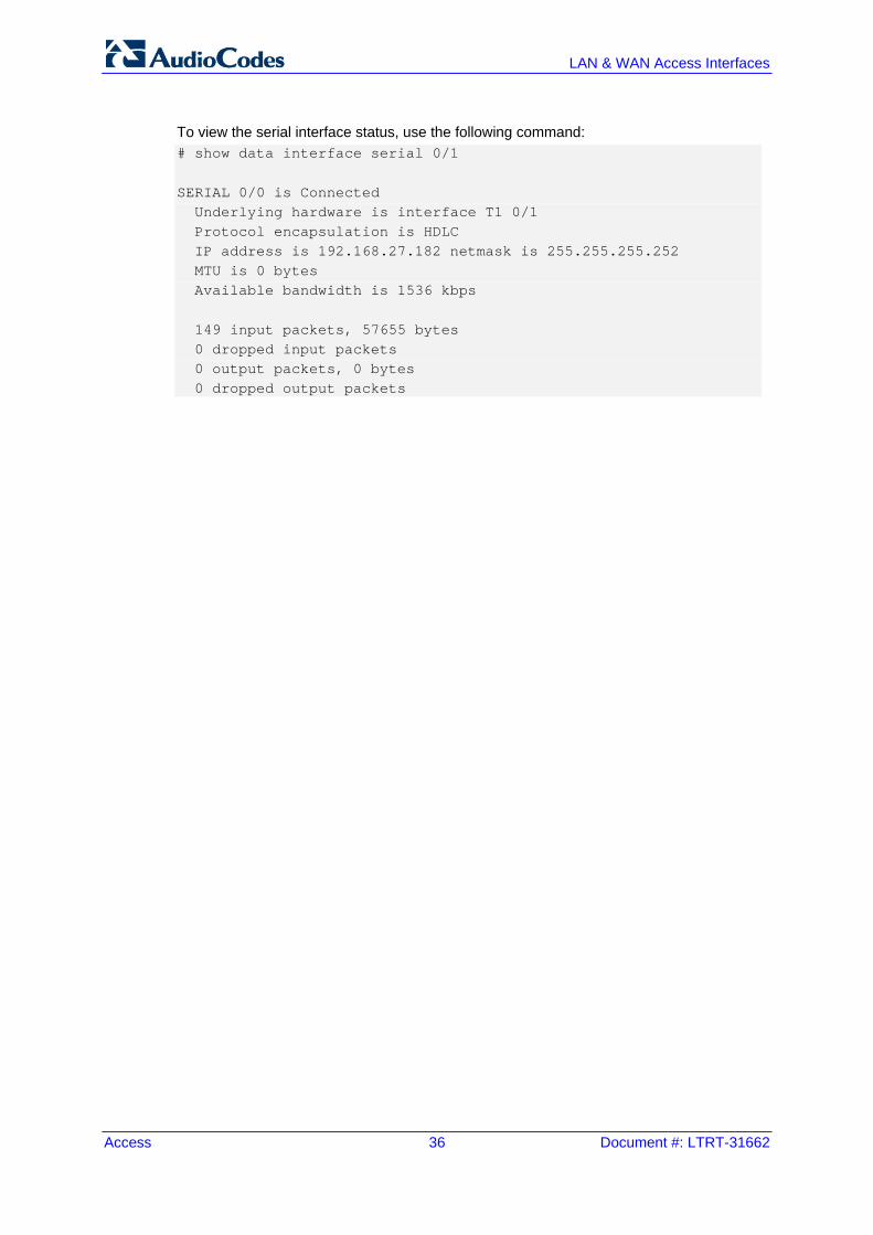
To view the serial interface status, use the following command: # show data interface serial 0/1 SERIAL 0/0 is Connected Underlying hardware is interface T1 0/1 Protocol encapsulation is HDLC IP address is 192.168.27.182 netmask is 255.255.255.252 MTU is 0 bytes Available bandwidth is 1536 kbps 149 input packets, 57655 bytes 0 dropped input packets 0 output packets, 0 bytes 0 dropped output packets

Version 6.8 37 Mediant MSBR
Configuration Guide 13. Fiber Optic
13 Fiber Optic Fiber-optic consist of a bundle of thin glass or plastic strands. This is coated or surrounded in material that allows light to pass through the fibers without escaping out the sides. Signals can pass through them at very high speeds from the point of origin to the destination, with minimal loss in quality or data. Companies use fiber-optics to transmit Internet data, audio information for telephones, and images for television or medical cameras. The concept behind fiber-optics is fairly simple. A user transmits a signal as light, often in the form of a laser beam, through a length of thin strands of glass or plastic. The optical fiber acts as the medium through which the light passes, while a coating on the outside of each strand keeps the light trapped within the fiber. People can send just about any type of digital data through fiber-optics, though conversion for some signals may be necessary. Telephones and Internet signals are often transmitted through fiber-optics. Companies simply convert phone audio signals into digital information, which can then be sent as light transmissions through the fibers. Many services convert the data into a binary signal of ones and zeroes, which they relay through pulses of light. Once a phone or other device receives the signal, it converts it back into audio information that the listener on the other end hears. Internet providers transmit data in much the same way, with computers converting digital signals into visible or auditory output. The important area of fibers is the physical layer and the use and differences between connectors and SFP (special external module that is used to connect specific connectors).
Command Description
# configure data Enter data configuration menu.
(config-data)# interface fiber slot/port
Enter the fiber interface commands. Optical fiber interfaces are exactly like a Layer-3 port and Gigabit Ethernet is the same as a fiber port.
(conf-if-FIBER slot/port)# ip address [IP] [Subnet Mask]
Configure the IP address of the fiber interface.
13.1 Examples This example shows a fiber interface configuration for creating a simple connection between the MSBR and the Service Provider:
Figure 13-1: Fiber Example
# configure data (config-data)# interface fiber 0/1 (conf-if-FIBER 0/1)# ip address 10.10.10.1 255.255.255.0 (conf-if-FIBER 0/1)# no shutdown (conf-if-FIBER 0/1)# exit (config-data)# ip route 0.0.0.0 0.0.0.0 fiber 0/1
MSBRFiber 0/1
Up To 80km Fiber Cable
Corporate Brach Users
Service Provider
MPLSInternet Network

Access 38 Document #: LTRT-31662
LAN & WAN Access Interfaces
This page is intentionally left blank.
Version 6.8 39 Mediant MSBR
Configuration Guide 14. WAN Failover
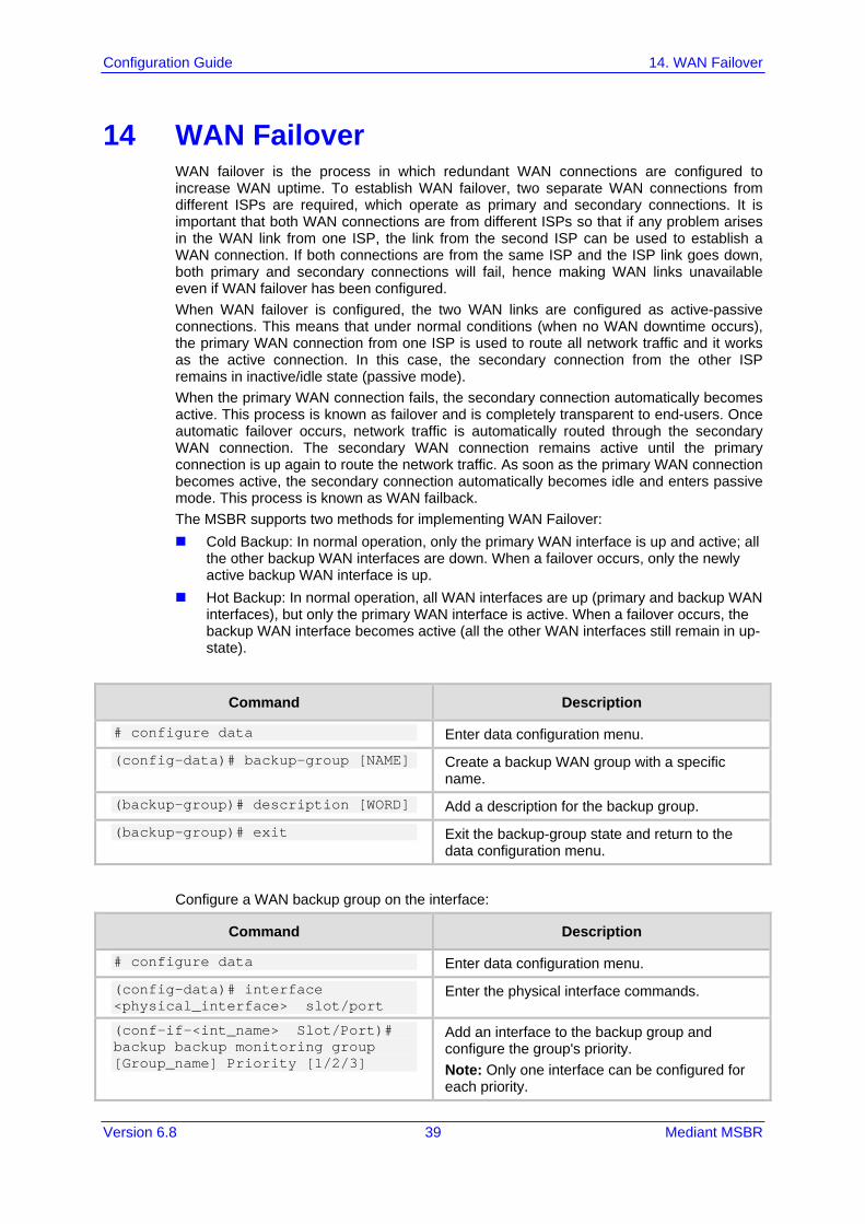
14 WAN Failover WAN failover is the process in which redundant WAN connections are configured to increase WAN uptime. To establish WAN failover, two separate WAN connections from different ISPs are required, which operate as primary and secondary connections. It is important that both WAN connections are from different ISPs so that if any problem arises in the WAN link from one ISP, the link from the second ISP can be used to establish a WAN connection. If both connections are from the same ISP and the ISP link goes down, both primary and secondary connections will fail, hence making WAN links unavailable even if WAN failover has been configured. When WAN failover is configured, the two WAN links are configured as active-passive connections. This means that under normal conditions (when no WAN downtime occurs), the primary WAN connection from one ISP is used to route all network traffic and it works as the active connection. In this case, the secondary connection from the other ISP remains in inactive/idle state (passive mode). When the primary WAN connection fails, the secondary connection automatically becomes active. This process is known as failover and is completely transparent to end-users. Once automatic failover occurs, network traffic is automatically routed through the secondary WAN connection. The secondary WAN connection remains active until the primary connection is up again to route the network traffic. As soon as the primary WAN connection becomes active, the secondary connection automatically becomes idle and enters passive mode. This process is known as WAN failback. The MSBR supports two methods for implementing WAN Failover: Cold Backup: In normal operation, only the primary WAN interface is up and active; all
the other backup WAN interfaces are down. When a failover occurs, only the newly active backup WAN interface is up.
Hot Backup: In normal operation, all WAN interfaces are up (primary and backup WAN interfaces), but only the primary WAN interface is active. When a failover occurs, the backup WAN interface becomes active (all the other WAN interfaces still remain in up-state).
Command Description
# configure data Enter data configuration menu.
(config-data)# backup-group [NAME] Create a backup WAN group with a specific name.
(backup-group)# description [WORD] Add a description for the backup group.
(backup-group)# exit Exit the backup-group state and return to the data configuration menu.
Configure a WAN backup group on the interface:
Command Description
# configure data Enter data configuration menu.
(config-data)# interface <physical_interface> slot/port
Enter the physical interface commands.
(conf-if-<int_name> Slot/Port)# backup backup monitoring group [Group_name] Priority [1/2/3]
Add an interface to the backup group and configure the group's priority. Note: Only one interface can be configured for each priority.

Access 40 Document #: LTRT-31662
LAN & WAN Access Interfaces
Configure a conditional route for Hot Backup:
Command Description
# configure data Enter data configuration menu.
(config-data)# track [track_ID] [icmpecho|icmpv6echo] [Network Destination] [Interface_track] [interval|retries]
track_ID: number identifier between 1 and 100 for track command.
icmpecho/icmpv6echo: choose between IPv4 and IPv6
Network Destination: Network commands tracks
Interface_track: interface on which command operates on
Interval: interval between probes Retries: how much time pass before track
goes down.
14.1 Examples
14.1.1 Cold Backup WAN Failover This example shows configuration for a Cold Backup WAN failover. The MSBR needs to be configured so that when the ATM connection fails, the 3G cellular modem becomes active.
Figure 14-1: WAN Failover Example
(config-data)# backup-group wan_failover (backup-group)# exit (config-data)# interface atm 0/0 (conf-if-atm0/0)# backup monitoring group wan_failover Priority 1 (config-data)# interface Cellular 0/0 (conf-if-cel0/0)# backup monitoring group wan_failover Priority 2
To view the active interface, use the following command:
USB 3GCellular Modem
MSBR
AD
SL connection
ATM
connection
Service Provider
MPLSInternet Network

Version 6.8 41 Mediant MSBR
Configuration Guide 14. WAN Failover
# show data backup-group Group Name: wan_failover Priority 1 atm 0/0 Priority 2 Cellular 0/0 Priority 3 Currently active interface: atm 0/0
After the atm 0/0 interface disconnects, the show command displays the following: # show data backup-group Group Name: wan_failover Priority 1 atm 0/0 Priority 2 Cellular 0/0 Priority 3 Currently active interface: Cellular 0/0
14.1.2 Hot Backup WAN Failover The following configuration example demonstrates Hot Backup and is based on the previous example. 1. Set the monitor routing for the primary default route:
(config-data)# track 1 icmpecho 8.8.8.8 atm 0/0 1 # first priority route – all traffic will be redirected to primary WAN (atm 0/0 interface). (config-data)# ip route 0.0.0.0 0.0.0.0 10.1.1.1 [Default Gateway] atm 0/0 track 1
2. Set the secondary WAN IP route: (config-data)# ip route 0.0.0.0 0.0.0.0 Cellular 0/0 100 # The metric 100 is set to create a secondary routing rule with lower priority, using Cellular 0/0 as the secondary WAN interface.
3. The traceroute command shows the path to the destination. The traceroute command shows how destination address 8.8.8.8 can be reached through the ATM interface. When the ATM interface is down, the destination 8.8.8.8 is reached through the cellular interface. # ATM is the active WAN interface: # traceroute 8.8.8.8 10.1.1.1 (10.1.1.254) 0.849 ms 0.337 ms 0.523 ms 10.1.1.254 (8.8.8.8) 0.745 ms 0.304 ms 0.511 ms # ATM is down and the cellular interface is the active WAN interface: # traceroute 8.8.8.8 172.30.254.108 (172.30.254.1) 0.802 ms 0.356 ms 0.540 ms 172.30.254.1 (8.8.8.8) 0.798 ms 0.347 ms 0.501 ms Traceroute: Destination reached

Access 42 Document #: LTRT-31662
LAN & WAN Access Interfaces
This page is intentionally left blank.

Version 6.8 43 Mediant MSBR
Configuration Guide 15. Wi-Fi
15 Wi-Fi Wi-Fi is a term for certain types of wireless local area networks (WLAN) that use specifications in the 802.11 family, Originally, Wi-Fi certification was applicable only to products using the 802.11b standard. Wi-Fi can apply to products that use any 802.11 standard. The 802.11 specifications are part of an evolving set of wireless network standards known as the 802.11 family. Any entity that has a wireless LAN should use security safeguards such as the Wired Equivalent Privacy (WEP) encryption standard, the more recent Wi-Fi Protected Access (WPA), Internet Protocol Security (IPsec), or a virtual private network (VPN).
Command Description
# configure data Enter data configuration menu.
(config-data)# no shutdown radio
Enable the Wireless interface.
(config-data)# interface dot11radio [Number_Radio]
Enter the radio interface configuration mode.
(conf-if-dot11radio 1)# beacon [dtim-period|period]
beacon: contains all the information about the network. Beacon frames are transmitted periodically to announce the presence of a Wireless LAN.
dtim-period: sets the data rate of the beacon interval [1-100].
period: sets the milliseconds of beacon interval [20-4000].
(conf-if-dot11radio 1)# ssid [NAME]
Configures the service set identifier (SSID) which uniquely identifies any given wireless network.
(conf-if-dot11radio 1)# mode [a,b,g,n,na,ngb,ngba]
Allows the interface to operate in a different 802.11 family protocols. 802.11a: transmits at 5 GHz and can
move up to 54 megabits of data per second. It also uses orthogonal frequency-division multiplexing (OFDM), a more efficient coding technique that splits that radio signals into several sub-signals before they reach a receiver. This greatly reduces interference.
802.11b: slowest and least expensive standard. 802.11b transmits in the 2.4 GHz frequency band of the radio spectrum. It can handle up to 11 megabits of data per second, and it uses complementary code keying (CCK) modulation to improve speeds.
802.11g: transmits at 2.4 GHz like 802.11b, but it's much faster. It can handle up to 54 megabits of data per second. 802.11g is faster because it uses the same OFDM coding as 802.11a.
802.11n: most widely available of the

Access 44 Document #: LTRT-31662
LAN & WAN Access Interfaces
Command Description
standards and is backward compatible with a, b and g. It significantly improved speed and range over its predecessors. For instance, although 802.11g theoretically moves 54 megabits of data per second, it only achieves real-world speeds of about 24 megabits of data per second because of network congestion. 802.11n, however, reportedly can achieve speeds as high as 140 megabits per second. 802.11n can transmit up to four streams of data, each at a maximum of 150 megabits per second, but most routers only allow for two or three streams.
(conf-if-dot11radio 1)# security [802.1x, mac , mode , wep , wpa]
Configures security on different types and modes on the radio interface. 802.1x: In a wireless LAN with 802.1X, a
user (known as the supplicant) requests access to an access point (known as the authenticator). The access point forces the user (actually, the user's client software) into an unauthorized state that allows the client to send only an EAP start message. The access point returns an EAP message requesting the user's identity. The client returns the identity, which is then forwarded by the access point to the authentication server, which uses an algorithm to authenticate the user and then returns an accept or reject message back to the access point. Assuming an accept is received, the access point changes the client's state to authorized and normal traffic can now take place. The authentication server may use the Remote Authentication Dial-In User Service (RADIUS).
wep: Wired Equivalent Privacy (WEP) is a security protocol, specified in the IEEE Wireless Fidelity (Wi-Fi) standard, 802.11b, that is designed to provide a wireless local area network (WLAN) with a level of security and privacy comparable to what is usually expected of a wired LAN. WEP seeks to establish similar protection to that offered by the wired network's physical security measures by encrypting data transmitted over the WLAN. Data encryption protects the vulnerable wireless link between clients and access points; once this measure has been taken, other typical LAN security mechanisms such as password protection, end-to-end encryption, virtual private networks

Version 6.8 45 Mediant MSBR
Configuration Guide 15. Wi-Fi
Command Description
(VPNs), and authentication can be put in place to ensure privacy.
wpa: Wi-Fi Protected Access (WPA) is a security standard for users of computers equipped with Wi-Fi wireless connection. It is an improvement on and is expected to replace the original Wi-Fi security standard, Wired Equivalent Privacy (WEP). WPA's encryption method is the Temporal Key Integrity Protocol (TKIP). TKIP addresses the weaknesses of WEP by including a per-packet mixing function, a message integrity check, an extended initialization vector, and a re-keying mechanism. WPA provides "strong" user authentication based on 802.1x and the Extensible Authentication Protocol (EAP). WPA depends on a central authentication server such as RADIUS to authenticate each user.
mac: allow or deny specific MAC addresses to the access point.
mode: Security mode. (conf-if-dot11radio 1)# channel [Channel_Number|width|auto]
802.11b, 802.11g, and 802.11n-2.4 use the 2.400 – 2.500 GHz spectrum. 802.11a and 802.11n use the more heavily regulated 4.915 – 5.825 GHz band. Each spectrum is sub-divided into channels with a center frequency and bandwidth The 2.4 GHz band is divided into 14 channels spaced 5 MHz apart, beginning with channel 1 which is centered on 2.412 GHz, 2 is centered on 2.417, and so on. width: Bandwidth in use (20Mhz Only, or
40/20 as dynamic). auto: scanning for best frequency to sign
interface. [number]: allows you to specify frequency
of the channels (between 1-13, 36-64,100-140,149-165).
(conf-if-dot11radio 1)# cts [mode|type]
Clear to send (CTS) protection mode is a wireless setting that ensures computers on a network can connect to a wireless router when many communications devices are present, network computers may experience difficulty in reaching the Internet as they all try to connect at the same time. When switched on, a computer must receive a CTS frame from the wireless access point (WAP) before information can be sent. An auto setting determines which computer can reach a WAP at a specific through a request to send (RTS) packet, Computers
Access 46 Document #: LTRT-31662
LAN & WAN Access Interfaces
Command Description
are unable to detect when other devices on a network attempt to transmit data. Without CTS, information collisions can occur, causing the WAP to return an error message to the originating computer. CTS determines the order in which computers contact the WAP: Mode: auto or none. Type: CTS-only (cts) and CTS-RTS
(rts_cts) are the two methods of protection: CTS-only: computers must receive a
self-directed CTS frame before sending data.
CTS-RTS: the computer must send an RTS and receive a CTS before transmission.
The rate of data transmission can also be adjusted to regulate how fast communication occurs.
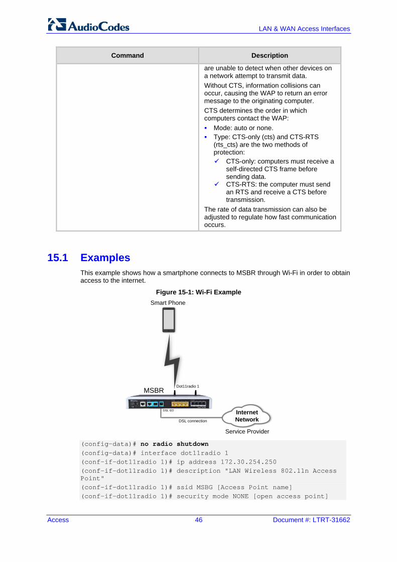
15.1 Examples This example shows how a smartphone connects to MSBR through Wi-Fi in order to obtain access to the internet.
Figure 15-1: Wi-Fi Example
(config-data)# no radio shutdown (config-data)# interface dot11radio 1 (conf-if-dot11radio 1)# ip address 172.30.254.250 (conf-if-dot11radio 1)# description "LAN Wireless 802.11n Access Point" (conf-if-dot11radio 1)# ssid MSBG [Access Point name] (conf-if-dot11radio 1)# security mode NONE [open access point]
DSL connection
DSL 0/2
Service Provider
MPLSInternet Network
Smart Phone
Dot11radio 1MSBR

Version 6.8 47 Mediant MSBR
Configuration Guide 15. Wi-Fi
(conf-if-dot11radio 1)# no security mac mode [allow all] (conf-if-dot11radio 1)# power 100 [full power signal] (conf-if-dot11radio 1)# beacon dtim-period 1 (conf-if-dot11radio 1)# beacon period 100 (conf-if-dot11radio 1)# wmm [Allow Multimedia] (conf-if-dot11radio 1)# no shutdown
Once you have performed the above configuration, the smartphone searches for an Access Point and locates the MSBR. To view device association with the specific radio/Wi-Fi interface of MSBR, use the following command: # show data dot11radio interface 1 dot11radio 1 is Connected. Description: LAN Wireless 802.11n Access Point Hardware address is 00:90:8f:48:cd:80 State Time: 0:03:09 Time since creation: 0:45:55 Time since last counters clear : 0:03:09 mtu auto network lan ssid MSBG broadcast security mode NONE no security mac mode mode ngb channel width 40/20 channel auto power 100 beacon dtim-period 1 beacon period 100 fragment threshold 2346 cts mode none cts type cts burst num 3 burst time 2 rts threshold 2346 wmm country code 0x178 (376) IPv6 is disabled rx_packets 67 rx_bytes 6942 rx_dropped 0 rx_errors 0 tx_packets 44 tx_bytes 5928 tx_dropped tx_errors 0 15-seconds input rate: 89 bits/sec, 0 packets/sec 15-seconds output rate: 89 bits/sec, 0 packets/sec 5-minutes input rate: 318 bits/sec, 0 packets/sec 5-minutes output rate: 271 bits/sec, 0 packets/sec no shutdown

Access 48 Document #: LTRT-31662
LAN & WAN Access Interfaces
To view device association with all radio/Wi-Fi interfaces of MSBR, use the following command: # show data dot11radio associations all dot11radio 1: ADDR CHAN RATE Power ec:85:2f:96:37:b2 9 52M 16dBm
15.2 Advanced Wi-Fi Example In this example, a guest laptop wishes to connect with Wi-Fi within office desk. The company does not want the guest to access the private network; only the internet. However, when one of the company's office PCs wants to sign in to MSBR, it needs to connect to another radio interface that allows connection to the private network office.
Figure 15-2: Wi-Fi Advanced Example
1. Configure two BVI interfaces and configure VLAN 1 and VLAN 2 as DHCP for different
networks (internet network and office private network): (config-data)# interface bvi 1 (conf-if-BVI 1)# no shutdown (conf-if-BVI 1)# ip address 192.168.0.1 255.255.255.0 (conf-if-BVI 1)# ip dhcp-server network 192.168.0.2 192.168.0.50 255.255.255.0 +(conf-if-BVI 1)# service dhcp (conf-if-BVI 1)# exit (config-data)# interface vlan 1 (conf-if-VLAN 1)# bridge-group 1 (conf-if-VLAN 1)# exit
DSL connectionDSL 0/2
Service Provider
MPLSInternet Network
Dot11radio 1MSBR
Guest Laptop
Dot11radio 2
Office PC
MPLSOffice Private Network
Gig 1/1

Version 6.8 49 Mediant MSBR
Configuration Guide 15. Wi-Fi
(config-data)# interface bvi 2 (conf-if-BVI 2)# no shutdown (conf-if-BVI 2)# ip address 172.30.0.1 255.255.255.0 (conf-if-BVI 2)# ip dhcp-server network 172.30.0.2 172.30.0.10 255.255.255.0 (conf-if-BVI 2)# service dhcp (conf-if-BVI 2)# exit (config-data)# interface vlan 2 (conf-if-VLAN 2)# bridge-group 2 (conf-if-VLAN 2)# exit
2. Perform the same configuration as in the example in Section 15.1 on page 46: (config-data)# no radio shutdown (config-data)# interface dot11radio 1 (conf-if-dot11radio 1)# bridge-group 1 (conf-if-dot11radio 1)# description "private network" (conf-if-dot11radio 1)# ssid MSBG [Access Point name] (conf-if-dot11radio 1)# security mode NONE [open access point] (conf-if-dot11radio 1)# no security mac mode [allow all] (conf-if-dot11radio 1)# power 100 [full power signal, effects all radio interfaces] (conf-if-dot11radio 1)# beacon dtim-period 1 (conf-if-dot11radio 1)# beacon period 100 (conf-if-dot11radio 1)# wmm [Allow Multimedia] (conf-if-dot11radio 1)# no shutdown (conf-if-dot11radio 1)# exit
3. Add another radio interface for the private network: (config-data)# interface dot11radio 2 (conf-if-dot11radio 1)# bridge-group 2 (conf-if-dot11radio 1)# description "internet network" (conf-if-dot11radio 1)# ssid MSBG_Private [Access Point name] (conf-if-dot11radio 1)# power 100 (conf-if-dot11radio 1)# no shutdown (conf-if-dot11radio 1)# security wpa psk ascii 12345678 [if any guest try to connect he will need this password] (conf-if-dot11radio 1)# security wpa mode psk (conf-if-dot11radio 1)# security wpa enc alg TKIP_AES (conf-if-dot11radio 1)# security mode WPA_WPA2 (conf-if-dot11radio 1)# no security mac mode (conf-if-dot11radio 1)# channel mode auto [choose frequency automatically] (conf-if-dot11radio 1)# exit (config-data)# access-list 1 deny ip 172.30.0.0 0.0.0.255 192.168.0.0 0.0.0.255 [deny any device that assigned through wifi connection to private network]

Access 50 Document #: LTRT-31662
LAN & WAN Access Interfaces
This page is intentionally left blank.

Version 6.8 51 Mediant MSBR
Configuration Guide 16. LLDP
16 LLDP MSBR supports the LLDP protocol. To configure LLDP, perform the following configuration:
Command Description
# configure data Enter the data configuration level.
(config-data)# lldp timer 5 Set the LLDP transmission timer to 5 seconds.
(config-data)# lldp run Enable LLDP.
To view the neighbors discovered by LLDP, use the following command:
Command Description
# sh data lldp neighbors Displays LLDP neighbors.
16.1 Examples To configure LLDP: # configure data (config-data)# lldp timer 5 (config-data)# lldp network-policy profile 1 (conf-lldp-pol-1)# voice vlan 1 (conf-lldp-pol-1)# cos 5 (conf-lldp-pol-1)# dscp 46 (conf-lldp-pol-1)# exit (config-data)# lldp network-policy profile 2 (conf-lldp-pol-2)# video vlan 2 (conf-lldp-pol-2)# cos 6 (conf-lldp-pol-2)# dscp 40 (conf-lldp-pol-2)# exit (config-data)# lldp run To view LLDP neighbors, use the following command: # sh data lldp neighbors LLDP totals: received 60 packets, sent 62 packets ++ 00:90:8f:4b:bd:d7 on interface GigabitEthernet 4/2 Received 56 LLDPDUs, timeout 25 seconds Capabilities: Router Bridge Port description: GigabitEthernet 4/3
The MAC address, 00:90:8f:4b:bd:d7 belongs to an adjacent MSBR. The adjacent MSBR port GigabitEthernet 4/3 is connected to port GigabitEthernet 4/2 of the local MSBR where the command show data lldp neighbors was issued.

Access 52 Document #: LTRT-31662
LAN & WAN Access Interfaces
Once LLDP is configured, the debug capture shows that the LLDP packet provides two different VLANs with suitable parameters:
Figure 16-1: LLDP

Version 6.8 53 Mediant MSBR
Configuration Guide 16. LLDP
This page is intentionally left blank.

Configuration Guide
www.audiocodes.com