configuring broadband access: ppp and routed bridge ... · the ppp interface is brought up using...
TRANSCRIPT

WC-119Cisco IOS Wide-Area Networking Configuration Guide
Configuring Broadband Access: PPP and Routed Bridge Encapsulation
This chapter describes how to configure a central office aggregator for broadband access using PPP or ATM routed bridge encapsulation.
This chapter includes the following sections:
• Configuring PPP over ATM
• Configuring PPPoE over ATM
• Configuring PPPoE over Ethernet
• Configuring PPPoE over IEEE 802.1Q VLANs
• Configuring RADIUS Port Identification for PPP
• Configuring ATM Routed Bridge Encapsulation
• Configuring an ATM PVC Range
• Configuration Examples
For further general information about broadband access using PPP or ATM routed bridge encapsulation, see the “Wide-Area Networking Overview” chapter at the beginning of this book.
For a complete description of the commands in this chapter that are specific to broadband access configuration, refer to the chapter “Broadband Access: PPP and Routed Bridge Encapsulation Commands” in the Cisco IOS Wide-Area Networking Command Reference. To locate documentation of other commands that appear in this chapter, use the command reference master index or search online.
To identify the hardware platform or software image information associated with a feature, use the Feature Navigator on Cisco.com to search for information about the feature or refer to the software release notes for a specific release. For more information, see the section “Identifying Supported Platforms” in the chapter “Using Cisco IOS Software.”
Configuring PPP over ATMPPP over ATM can be configured on all platforms running Cisco IOS Release 12.1 or later, except for IETF-compliant LLC encapsulated PPP over ATM, which is not available for the Cisco MC3810 series platform.
Note All forms of PPP over ATM are now supported on the ATM port adapters, except for the PA-A1 ATM port adapter for Cisco IOS Release 12.1. All forms of PPP over ATM are now supported on the enhanced ATM port adapter for Cisco IOS Release 12.1 or later.

Configuring Broadband Access: PPP and Routed Bridge EncapsulationConfiguring PPP over ATM
WC-120Cisco IOS Wide-Area Networking Configuration Guide
Figure 10 shows a typical scenario for using Cisco-proprietary PPP over ATM.
Figure 10 PPP-over-ATM Network Environment
Note If you need to configure the Cisco MGX 8220 shelf for frame forwarding at the remote sites, refer to the Cisco MGX 8220 Command Supplement for command line instructions or the Cisco StrataView Plus Operations Guide for StrataView Plus instructions. If you configure the MGX using the command line interface, use the addport and addchan commands and select frame forwarding for the port_type and chan_type arguments, respectively.
When you configure PPP over ATM, a logical interface known as a virtual access interface associates each PPP connection with an ATM VC. You can create this logical interface by configuring an ATM PVC or SVC. This configuration encapsulates each PPP connection in a separate PVC or SVC, allowing each PPP connection to terminate at the router ATM interface as if received from a typical PPP serial interface.
The virtual access interface for each VC obtains its configuration from a virtual interface template (virtual template) when the VC is created. Before you create the ATM VC, it is recommended that you create and configure a virtual template as described in the secrtion “Creating and Configuring a Virtual Template,” next.
Once you have configured the router for PPP over ATM, the PPP subsystem starts and the router attempts to send a PPP configure request to the remote peer. If the peer does not respond, the router periodically goes into a “listen” state and waits for a configuration request from the peer. After a timeout (typically 45 seconds), the router again attempts to reach the remote router by sending configuration requests.
The virtual access interface remains associated with a VC as long as the VC is configured. If you deconfigure the VC, the virtual access interface is marked as deleted. If you shut down the associated ATM interface, you will also cause the virtual access interface to be marked as down (within 10 seconds), and you will bring the PPP connection down. If you set a keepalive timer of the virtual template on the interface, the virtual access interface uses the PPP echo mechanism to verify the existence of the remote peer.
LAN
LAN
LAN
LAN
Router
Router
Router
Router
RouterRouter
LAN
Remotebranchoffices
Central or regional site
Dedicated leasedlines
Private or carrierwide-area network
Configured for PPPover ATM
ATM
BPX
MGX
MGX File server
S58
28
LAN

Configuring Broadband Access: PPP and Routed Bridge EncapsulationConfiguring PPP over ATM
WC-121Cisco IOS Wide-Area Networking Configuration Guide
The following three types of PPP over ATM connections are supported:
• IETF-compliant MUX encapsulated PPP over ATM
• IETF-compliant LLC encapsulated PPP over ATM
• Cisco-proprietary PPP over ATM
PPP over ATM Configuration Task ListTo configure PPP over ATM, complete the tasks described in the following sections. Each task is identified as optional or required:
• Creating and Configuring a Virtual Template (Optional, but recommended)
• Configuring IETF-Compliant MUX Encapsulated PPP over ATM PVCs (Optional)
• Configuring IETF-Compliant LLC Encapsulated PPP over ATM PVCs (Optional)
• Configuring Cisco-Proprietary PPP over ATM PVCs (Optional)
• Configuring PPP over ATM SVCs (Optional)
Creating and Configuring a Virtual Template
Prior to configuring the ATM PVC for PPP over ATM, you typically create and configure a virtual template. To create and configure a virtual template, use the following commands beginning in global configuration mode:
Other optional configuration commands can be added to the virtual template configuration. For example, you can enable the PPP authentication on the virtual template using the ppp authentication chap command. Refer to the “Configuring Virtual Template Interfaces” chapter in the Cisco IOS Dial Technologies Configuration Guide for additional information about configuring the virtual template.
All PPP parameters are managed within the virtual template configuration. Configuration changes made to the virtual template are automatically propagated to the individual virtual access interfaces. Multiple virtual access interfaces can originate from a single virtual template; therefore, multiple PVCs can use a single virtual template.
Cisco IOS software supports up to 25 virtual template configurations. If greater numbers of tailored configurations are required, an authentication, authorization, and accounting (AAA) server may be employed. Refer to the “Configuring Per-User Configuration” chapter in the Cisco IOS Dial Technologies Configuration Guide for additional information on configuring an AAA server.
If the parameters of the virtual template are not explicitly defined before the ATM PVC is configured, the PPP interface is brought up using default values from the virtual template identified. Some parameters (such as an IP address) take effect only if specified before the PPP interface comes up. Therefore, it is recommended that you explicitly create and configure the virtual template before configuring the ATM PVC to ensure that such parameters take effect. Alternatively, if parameters are
Command Purpose
Step 1 Router(config)# interface virtual-template number
Creates a virtual template, and enter interface configuration mode.
Step 2 Router(config-if)# encapsulation ppp Enables PPP encapsulation on the virtual template.
Step 3 Router(config-if)# ip unnumbered ethernet number
(Optional) Enables IP without assigning a specific IP address on the LAN.

Configuring Broadband Access: PPP and Routed Bridge EncapsulationConfiguring PPP over ATM
WC-122Cisco IOS Wide-Area Networking Configuration Guide
specified after the ATM PVC has already been configured, use the shutdown command followed by a no shutdown command on the ATM subinterface to restart the interface; this restart will cause the newly configured parameters (such as an IP address) to take effect.
Network addresses for the PPP-over-ATM connections are not configured on the main ATM interface or subinterface. Instead, these are configured on the appropriate virtual template or obtained via AAA.
The virtual templates support all standard PPP configuration commands; however, not all configurations are supported by the PPP-over-ATM virtual access interfaces. These restrictions are enforced at the time the virtual template configuration is applied (cloned) to the virtual access interface. These restrictions are described in the following paragraphs.
Only standard FIFO queuing is supported when applied to PPP-over-ATM virtual access interfaces. Other types of queuing which are typically configured on the main interface are not (for example, fair queuing). If configured, these configuration lines are ignored when applied to a PPP-over-ATM interface.
Although fast switching is supported, flow and optimum switching are not; these configurations are ignored on the PPP-over-ATM virtual access interface. Fast switching is enabled by default for the virtual template configuration. If fast switching is not desired, use the no ip route-cache command to disable it.
The PPP reliable link that uses Link Access Procedure, Balanced (LAPB) is not supported.
Because an ATM PVC or SVC is configured for this feature, the following standard PPP features are not applicable and should not be configured:
• Asynchronous interfaces
• Dialup connections
• Callback on PPP
Configuring IETF-Compliant MUX Encapsulated PPP over ATM PVCs
IETF-compliant MUX encapsulated PPP over ATM, also known as null encapsulation, allows you to configure PPP over ATM using a virtual circuit (VC) multiplexed encapsulation mode. This feature complies with IETF RF 2364 entitled PPP over AAL5.
You can configure ATM PVCs for IETF-compliant MUX encapsulated PPP over ATM on either point-to-point or multipoint subinterfaces. Multiple PVCs on multipoint subinterfaces significantly increase the maximum number of PPP-over-ATM sessions running on a router.

Configuring Broadband Access: PPP and Routed Bridge EncapsulationConfiguring PPP over ATM
WC-123Cisco IOS Wide-Area Networking Configuration Guide
To configure a PVC with IETF-compliant MUX PPP over ATM that supports VC multiplexed PPP payloads, use the following commands starting in global configuration mode:
To configure a PVC range with IETF-compliant MUX PPP over ATM that supports VC multiplexed PPP payloads, use the following commands beginning in global configuration mode:
IETF-Compliant PPP over ATM is not supported on ATM SVCs and can only be applied to PVCs.
Command Purpose
Step 1 Router(config)# interface atm slot/port.subinterface-number point-to-point
or
Router(config)# interface atm number.subinterface-number point-to-point
or
Router(config)# interface atm slot/port.subinterface-number multipoint
or
Router(config)# interface atm number.subinterface-number multipoint
Specifies an ATM point-to-point or multipoint subinterface using the appropriate format of the interface atm command.1
1. To determine the correct form of the interface atm command, consult your ATM network module, port adapter, or router documentation.
Step 2 Router(config-subif)# pvc [name] vpi/vci Configures the PVC.
Step 3 Router(config-if-atm-vc)# encapsulation aal5mux ppp virtual-template number
Configures VC multiplexed encapsulation on a PVC.
Command Purpose
Step 1 Router(config)# interface atm slot/port.subinterface-number point-to-point
or
Router(config)# interface atm number.subinterface-number point-to-point
or
Router(config)# interface atm slot/port.subinterface-number multipoint
or
Router(config)# interface atm number.subinterface-number multipoint
Specifies an ATM point-to-point or multipoint subinterface using the appropriate format of the interface atm command.1
1. To determine the correct form of the interface atm command, consult your ATM network module, port adapter, or router documentation.
Step 2 Router(config-subif)# range [range-name] pvc start-vpi/start-vci end-vpi/end-vci
Creates a range of PVCs.
Step 3 Router(config-if-atm-range)# encapsulation aal5mux ppp virtual-template number
Configures VC multiplexed encapsulation on a PVC range.

Configuring Broadband Access: PPP and Routed Bridge EncapsulationConfiguring PPP over ATM
WC-124Cisco IOS Wide-Area Networking Configuration Guide
The IETF-Compliant PPP over ATM feature was designed to support installations with ADSL circuits. For an example of using ADSL termination, see the section “ADSL Termination Example” under “PPP over ATM Configuration Examples” at the end of this chapter.
Configuring IETF-Compliant LLC Encapsulated PPP over ATM PVCs
IETF-compliant LLC encapsulated PPP over ATM LLC Encapsulation allows you to configure PPP over ATM with LLC encapsulation. It accommodates Frame Relay-to-ATM service interworking (Frame Relay forum standard FRF.8). There is no equivalent VC multiplexed encapsulation mode for Frame Relay; therefore, LLC encapsulation is required for Frame Relay-to-ATM networking. This version of PPP over ATM also enables you to carry multiprotocol traffic. For example, a VC will carry both PPP and IPX traffic.
Figure 11 illustrates Frame Relay-to-ATM interworking.
Figure 11 Frame Relay-to-ATM Interworking
You can configure ATM PVCs for IETF-compliant LLC encapsulated PPP over ATM on either point-to-point or multipoint subinterfaces. Multiple PVCs on multipoint subinterfaces significantly increase the maximum number of PPP-over-ATM sessions running on a router.
To configure IETF-compliant LLC encapsulated PPP over ATM on a PVC, use the following commands beginning in global configuration mode:
FRF.8SIU
Router
ATMFrameRelay 17
270
Command Purpose
Step 1 Router(config)# interface atm slot/port.subinterface-number point-to-point
or
Router(config)# interface atm number.subinterface-number point-to-point
or
Router(config)# interface atm slot/port.subinterface-number multipoint
or
Router(config)# interface atm number.subinterface-number multipoint
Specifies an ATM point-to-point or multipoint subinterface using the appropriate format of the interface atm command.1
Step 2 Router(config-subif)# pvc [name] vpi/vci Configures the PVC.

Configuring Broadband Access: PPP and Routed Bridge EncapsulationConfiguring PPP over ATM
WC-125Cisco IOS Wide-Area Networking Configuration Guide
To configure IETF-compliant LLC encapsulated PPP over ATM on a PVC range, use the following commands beginning in global configuration mode:
For more information about configuring an ATM PVC range, see the section “Configuring an ATM PVC Range” later in this chapter.
You can also configure IETF-compliant LLC encapsulated PPP over ATM in a VC class and apply this VC class to an ATM VC, subinterface, or interface. For information about configuring a VC class, refer to the section “Configuring VC Classes” in the chapter “Configuring ATM.”
Step 3 Router(config-if-atm-vc)# encapsulation aal5snap2 Configures LLC SNAP encapsulation on the PVC.
Step 4 Router(config-if-atm-vc)# protocol ppp virtual-template number
Configures IETF PPP over ATM LLC Encapsulation on the PVC.
1. To determine the correct form of the interface atm command, consult your ATM network module, port adapter, or router documentation.
2. The snap encapsulation is a misnomer here, since this encapsulation configures both LLC and SNAP encapsulation on the VC. If snap encapsulation is not configured at a lower inheritance level, or another type of encapsulation is configured at a lower inheritance level, you will have to configure both snap and the protocol ppp command to ensure that PPP over ATM with LLC encapsulation is configured on your VC.
Command Purpose
Command Purpose
Step 1 Router(config)# interface atm slot/port.subinterface-number point-to-point
or
Router(config)# interface atm number.subinterface-number point-to-point
or
Router(config)# interface atm slot/port.subinterface-number multipoint
or
Router(config)# interface atm number.subinterface-number multipoint
Specifies an ATM point-to-point or multipoint subinterface using the appropriate format of the interface atm command.1
1. To determine the correct form of the interface atm command, consult your ATM network module, port adapter, or router documentation.
Step 2 Router(config-subif)# range [range-name] pvc start-vpi/start-vci end-vpi/end-vci
Creates a range of PVCs.
Step 3 Router(config-if-atm-range)# encapsulation aal5snap2
2. The snap encapsulation is a misnomer here, since this encapsulation configures both LLC and SNAP encapsulation on the VC. If snap encapsulation is not configured at a lower inheritance level, or another type of encapsulation is configured at a lower inheritance level, you will have to configure both snap and the protocol ppp command to ensure that PPP over ATM with LLC encapsulation is configured on your VC.
Configures LLC SNAP encapsulation on the PVC range.
Step 4 Router(config-if-atm-range)# protocol ppp virtual-template number
Configures IETF PPP over ATM LLC Encapsulation on the PVC. range
Configuring Broadband Access: PPP and Routed Bridge EncapsulationConfiguring PPP over ATM
WC-126Cisco IOS Wide-Area Networking Configuration Guide
Note Depending on whether you configure IETF-compliant LLC encapsulated PPP over ATM directly on a PVC or interface, your PVC will inherit the configuration that takes highest precedence. For a description of the inheritance hierarchy, see the protocol command in the Cisco IOS Wide-Area Networking Command Reference Guide.
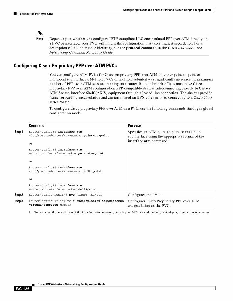
Configuring Cisco-Proprietary PPP over ATM PVCs
You can configure ATM PVCs for Cisco proprietary PPP over ATM on either point-to-point or multipoint subinterfaces. Multiple PVCs on multiple subinterfaces significantly increases the maximum number of PPP-over-ATM sessions running on a router. Remote branch offices must have Cisco proprietary PPP over ATM configured on PPP-compatible devices interconnecting directly to Cisco’s ATM Switch Interface Shelf (AXIS) equipment through a leased-line connection. The shelves provide frame forwarding encapsulation and are terminated on BPX cores prior to connecting to a Cisco 7500 series router.
To configure Cisco proprietary PPP over ATM on a PVC, use the following commands starting in global configuration mode:
Command Purpose
Step 1 Router(config)# interface atm slot/port.subinterface-number point-to-point
or
Router(config)# interface atm number.subinterface-number point-to-point
or
Router(config)# interface atm slot/port.subinterface-number multipoint
or
Router(config)# interface atm number.subinterface-number multipoint
Specifies an ATM point-to-point or multipoint subinterface using the appropriate format of the interface atm command.1
1. To determine the correct form of the interface atm command, consult your ATM network module, port adapter, or router documentation.
Step 2 Router(config-subif)# pvc [name] vpi/vci Configures the PVC.
Step 3 Router(config-if-atm-vc)# encapsulation aal5ciscoppp virtual-template number
Configures Cisco Proprietary PPP over ATM encapsulation on the PVC.

Configuring Broadband Access: PPP and Routed Bridge EncapsulationConfiguring PPP over ATM
WC-127Cisco IOS Wide-Area Networking Configuration Guide
To configure Cisco proprietary PPP over ATM on a PVC range, use the following commands beginning in global configuration mode:
For more information about configuring an ATM PVC range, see the section “Configuring an ATM PVC Range” later in this chapter.
For an example of configuring Cisco proprietary PPP over ATM, see the section “Configuring Cisco-Proprietary PPP over ATM PVCs” at the end of this chapter.
Configuring PPP over ATM SVCs
When PPP over ATM is configured over an SVC rather than a PVC, each time an end user initiates a connection to a Network Access Provider (NAP) or Network Service Provider (NSP), an ATM SVC is established using a configured ATM address. A PPP session is then established over the SVC. By using PPP, the NAPs and NSPs can authenticate users and provide suitable access to the various services being offered. Whereas PVCs require that services and destination addresses be predetermined, using PPP over ATM SVCs allows users to choose services and the quality of those services dynamically on the basis of destination address.
Figure 12 shows a typical network topology for PPP over ATM SVCs terminating at an NAP.
Figure 12 PPP over ATM SVC Terminating at an NAP
Command Purpose
Step 1 Router(config)# interface atm slot/port.subinterface-number point-to-point
or
Router(config)# interface atm number.subinterface-number point-to-point
or
Router(config)# interface atm slot/port.subinterface-number multipoint
or
Router(config)# interface atm number.subinterface-number multipoint
Specifies an ATM point-to-point or multipoint subinterface using the appropriate format of the interface atm command.1
1. To determine the correct form of the interface atm command, consult your ATM network module, port adapter, or router documentation.
Step 2 Router(config-subif)# range [range-name] pvc start-vpi/start-vci end-vpi/end-vci
Configures the PVC range.
Step 3 Router(config-if-atm-range)# encapsulation aal5ciscoppp virtual-template number
Configures Cisco-Proprietary PPP over ATM encapsulation on the PVC range.
44412DSL
DSLaccess
multiplexer
Networkaccessprovider
Networkserviceprovider
ATM IP
Configuring Broadband Access: PPP and Routed Bridge EncapsulationConfiguring PPP over ATM
WC-128Cisco IOS Wide-Area Networking Configuration Guide
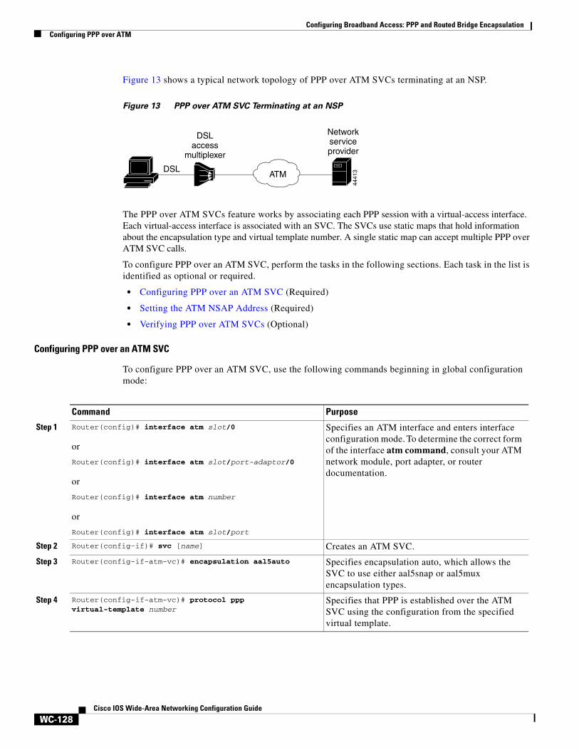
Figure 13 shows a typical network topology of PPP over ATM SVCs terminating at an NSP.
Figure 13 PPP over ATM SVC Terminating at an NSP
The PPP over ATM SVCs feature works by associating each PPP session with a virtual-access interface. Each virtual-access interface is associated with an SVC. The SVCs use static maps that hold information about the encapsulation type and virtual template number. A single static map can accept multiple PPP over ATM SVC calls.
To configure PPP over an ATM SVC, perform the tasks in the following sections. Each task in the list is identified as optional or required.
• Configuring PPP over an ATM SVC (Required)
• Setting the ATM NSAP Address (Required)
• Verifying PPP over ATM SVCs (Optional)
Configuring PPP over an ATM SVC
To configure PPP over an ATM SVC, use the following commands beginning in global configuration mode:
4441
3DSL
DSLaccess
multiplexer
Networkserviceprovider
ATM
Command Purpose
Step 1 Router(config)# interface atm slot/0
or
Router(config)# interface atm slot/port-adaptor/0
or
Router(config)# interface atm number
or
Router(config)# interface atm slot/port
Specifies an ATM interface and enters interface configuration mode. To determine the correct form of the interface atm command, consult your ATM network module, port adapter, or router documentation.
Step 2 Router(config-if)# svc [name] Creates an ATM SVC.
Step 3 Router(config-if-atm-vc)# encapsulation aal5auto Specifies encapsulation auto, which allows the SVC to use either aal5snap or aal5mux encapsulation types.
Step 4 Router(config-if-atm-vc)# protocol ppp virtual-template number
Specifies that PPP is established over the ATM SVC using the configuration from the specified virtual template.

Configuring Broadband Access: PPP and Routed Bridge EncapsulationConfiguring PPPoE over ATM
WC-129Cisco IOS Wide-Area Networking Configuration Guide
Setting the ATM NSAP Address
To set the network service access point (NSAP) address for the ATM interface, use the following command in interface configuration mode:
When configuring an SVC, you must use the atm nsap-address command to define the source NSAP address. It identifies a particular port on the ATM network and must be unique across the network.
Verifying PPP over ATM SVCs
To verify the configuration of PPP over ATM SVCs, use the following privileged EXEC command:
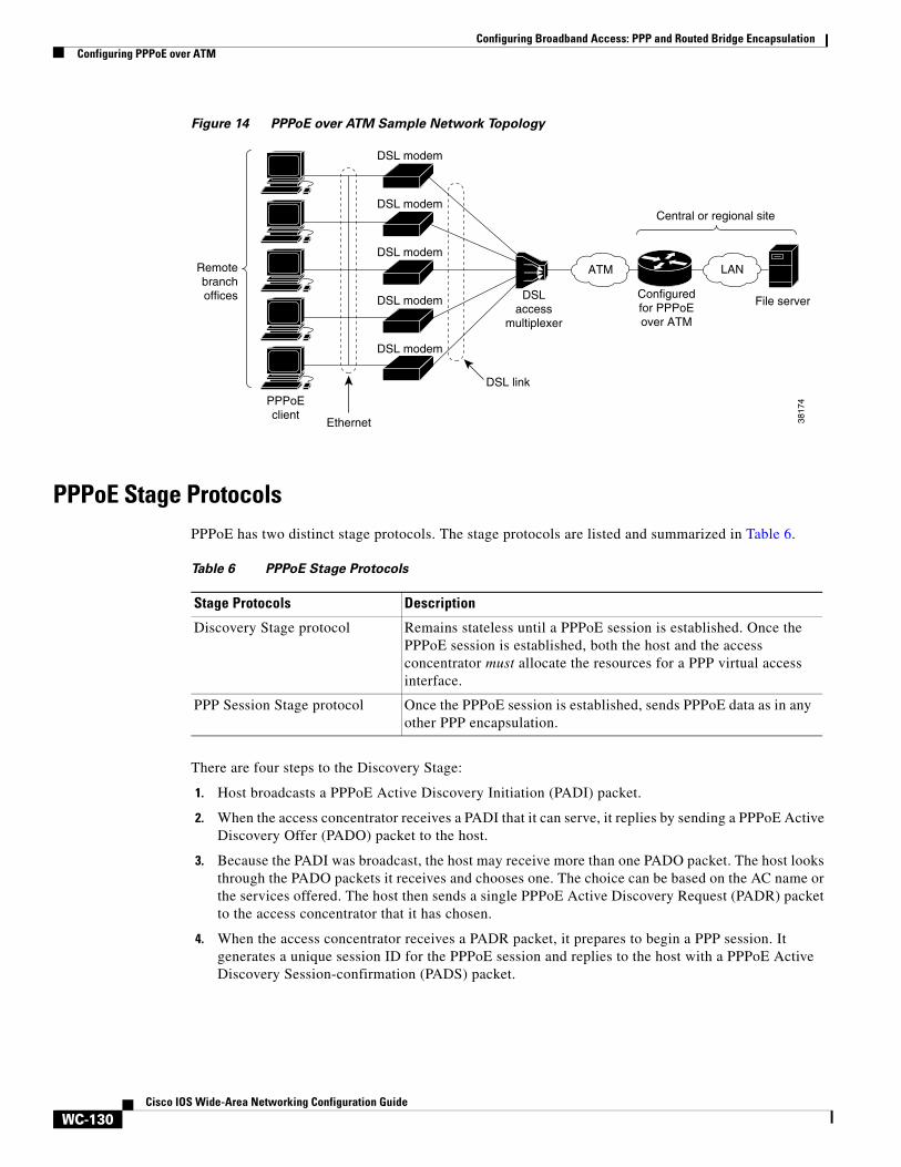
Configuring PPPoE over ATMPPPoE over ATM provides the ability to connect a network of hosts over a simple bridging-access device to a remote access concentrator. With this model, each host utilizes its own PPPoE stack and the user is presented with a familiar user interface. Access control, billing, and type of service can be configured on a per-user, rather than a per-site, basis. Before a point-to-point connection over Ethernet can be provided, each PPP session must learn the Ethernet address of the remote peer and establish a unique session identifier. A unique session identifier is provided by the PPPoE Discovery Stage protocol.
Figure 14 shows a sample network topology using PPPoE over ATM.
Step 5 Router(config-if-atm-vc)# max vc number Specifies the maximum number of SVCs that can be established using the current configuration.
Step 6 Router(config-if-atm-vc)# max bandwidth kbps Specifies the total amount of bandwidth available to all SVCs in the current configuration.
Command Purpose
Command PurposeRouter(config-if)# atm nsap-address nsap-address Sets the NSAP address for an ATM interface.
Command Purpose
Router# show atm svc Display sall ATM SVCs and traffic information.
Router# show atm svc ppp Displays information about each SVC configured for PPP over ATM.
Configuring Broadband Access: PPP and Routed Bridge EncapsulationConfiguring PPPoE over ATM
WC-130Cisco IOS Wide-Area Networking Configuration Guide
Figure 14 PPPoE over ATM Sample Network Topology
PPPoE Stage ProtocolsPPPoE has two distinct stage protocols. The stage protocols are listed and summarized in Table 6.
There are four steps to the Discovery Stage:
1. Host broadcasts a PPPoE Active Discovery Initiation (PADI) packet.
2. When the access concentrator receives a PADI that it can serve, it replies by sending a PPPoE Active Discovery Offer (PADO) packet to the host.
3. Because the PADI was broadcast, the host may receive more than one PADO packet. The host looks through the PADO packets it receives and chooses one. The choice can be based on the AC name or the services offered. The host then sends a single PPPoE Active Discovery Request (PADR) packet to the access concentrator that it has chosen.
4. When the access concentrator receives a PADR packet, it prepares to begin a PPP session. It generates a unique session ID for the PPPoE session and replies to the host with a PPPoE Active Discovery Session-confirmation (PADS) packet.
PPPoEclient
Ethernet
Remotebranchoffices
Central or regional site
DSL link
DSL modem
DSL modem
DSL modem
DSL modem
DSL modem
DSLaccess
multiplexer
Configuredfor PPPoEover ATM
ATM
File server
3817
4
LAN
Table 6 PPPoE Stage Protocols
Stage Protocols Description
Discovery Stage protocol Remains stateless until a PPPoE session is established. Once the PPPoE session is established, both the host and the access concentrator must allocate the resources for a PPP virtual access interface.
PPP Session Stage protocol Once the PPPoE session is established, sends PPPoE data as in any other PPP encapsulation.

Configuring Broadband Access: PPP and Routed Bridge EncapsulationConfiguring PPPoE over ATM
WC-131Cisco IOS Wide-Area Networking Configuration Guide
When a host wishes to initiate a PPPoE session, it must first perform discovery to identify the Ethernet MAC address of the peer and establish a PPPoE session ID. Although PPP defines a peer-to-peer relationship, discovery is inherently a client/server relationship. In the discovery process, a host (the client) discovers an access concentrator (the server). Depending on the network topology, there may be more than one access concentrator with which the host can communicate. The Discovery Stage allows the host to discover all access concentrators and then select one. When discovery is completed, both the host and the selected access concentrator have the information they will use to build their point-to-point connection over Ethernet.
PPPoE over ATM Conditions and RestrictionsNote the following conditions and restrictions for PPPoE over ATM:
• PPPoE will not be supported on any other LAN interfaces, such as FDDI and Token Ring.
• Fast switching is supported. PPPoE over ATM forwarding information base (FIB) switching will be supported for IP. All other protocols will be switched over process switching.
• Bridging is supported on the ATM PVCs running PPPoE.
• PPPoE will be supported on ATM PVCs compliant with RFC 1483 only.
• Only dial-in mode will be supported. Dial-out mode will not be supported.
• 2000 simultaneous PPP sessions are supported on the Cisco series 7200 with enhanced ATM port adapters and on the Cisco series 6400 platforms only, both with 128 MB of DRAM.
PPPoE over ATM Configuration Task ListSee the following sections for configuration tasks for PPPoE over ATM. Each task in the list indicates if the task is optional or required.
• Configuring a Virtual Template (Optional, but recommended)
• Configuring a VPDN Group for PPPoE over ATM (Required)
• Enabling PPPoE on an ATM PVC or PVC Range (Required)
Configuring a Virtual Template
Prior to configuring the VPDN group and the ATM PVC for PPPoE over ATM, you typically configure a virtual template. To configure a virtual template, see the section “Creating and Configuring a Virtual Template” earlier in this chapter.
Note Although Cisco Express Forwarding (CEF) switching is supported by PPPoE over ATM, fast switching, flow, and optimum switching are not; these configurations are ignored on the PPPoE-over-ATM virtual access interface. CEF is enabled by default for IP. All other protocol traffic will be processed switched.
Configuring Broadband Access: PPP and Routed Bridge EncapsulationConfiguring PPPoE over ATM
WC-132Cisco IOS Wide-Area Networking Configuration Guide
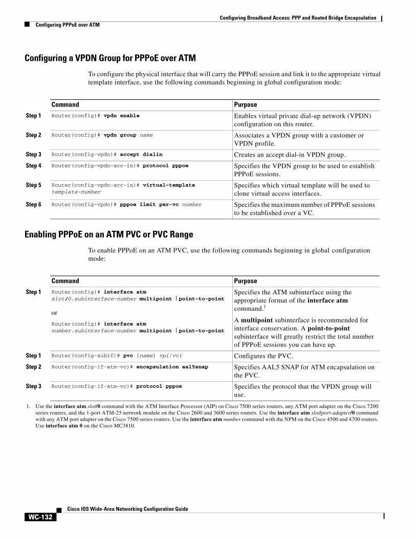
Configuring a VPDN Group for PPPoE over ATM
To configure the physical interface that will carry the PPPoE session and link it to the appropriate virtual template interface, use the following commands beginning in global configuration mode:
Enabling PPPoE on an ATM PVC or PVC Range
To enable PPPoE on an ATM PVC, use the following commands beginning in global configuration mode:
Command Purpose
Step 1 Router(config)# vpdn enable Enables virtual private dial-up network (VPDN) configuration on this router.
Step 2 Router(config)# vpdn group name Associates a VPDN group with a customer or VPDN profile.
Step 3 Router(config-vpdn)# accept dialin Creates an accept dial-in VPDN group.
Step 4 Router(config-vpdn-acc-in)# protocol pppoe Specifies the VPDN group to be used to establish PPPoE sessions.
Step 5 Router(config-vpdn-acc-in)# virtual-template template-number
Specifies which virtual template will be used to clone virtual access interfaces.
Step 6 Router(config-vpdn)# pppoe limit per-vc number Specifies the maximum number of PPPoE sessions to be established over a VC.
Command Purpose
Step 1 Router(config)# interface atm slot/0.subinterface-number multipoint | point-to-point
or
Router(config)# interface atm number.subinterface-number multipoint | point-to-point
Specifies the ATM subinterface using the appropriate format of the interface atm command.1
A multipoint subinterface is recommended for interface conservation. A point-to-point subinterface will greatly restrict the total number of PPPoE sessions you can have up.
1. Use the interface atm slot/0 command with the ATM Interface Processor (AIP) on Cisco 7500 series routers, any ATM port adapter on the Cisco 7200 series routers, and the 1-port ATM-25 network module on the Cisco 2600 and 3600 series routers. Use the interface atm slot/port-adapter/0 command with any ATM port adapter on the Cisco 7500 series routers. Use the interface atm number command with the NPM on the Cisco 4500 and 4700 routers. Use interface atm 0 on the Cisco MC3810.
Step 1 Router(config-subif)# pvc [name] vpi/vci Configures the PVC.
Step 2 Router(config-if-atm-vc)# encapsulation aal5snap Specifies AAL5 SNAP for ATM encapsulation on the PVC.
Step 3 Router(config-if-atm-vc)# protocol pppoe Specifies the protocol that the VPDN group will use.

Configuring Broadband Access: PPP and Routed Bridge EncapsulationConfiguring PPPoE over Ethernet
WC-133Cisco IOS Wide-Area Networking Configuration Guide
To enable PPPoE on an ATM PVC range, use the following commands beginning in gobal configuration mode:
Once you configure the router for PPPoE over ATM, the PPP subsystem starts and the router attempts to send a PPP configure request to the remote peer. If the peer does not respond, the router periodically goes into a “listen” state and waits for a configuration request from the peer. After a timeout (typically 45 seconds), the router again attempts to reach the remote router by sending configuration requests.
For more information about configuring an ATM PVC range, see the section “Configuring an ATM PVC Range” later in this chapter.
For an example of PPPoE over ATM, see the section “PPPoE over ATM Configuration Example” at the end of this chapter.
Configuring PPPoE over EthernetPPPoE over Ethernet enhances PPPoE functionality by adding direct connection to actual Ethernet and FastEthernet interfaces. PPPoE over Ethernet provides service-provider digital subscriber line (DSL) support by enabling multiple hosts on a shared Ethernet interface to open PPP sessions to multiple destinations with one or more bridging modems.
Note Fast switching is supported. PPPoE FIB switching will be supported for IP. All other protocols will be switched over process switching.
Command Purpose
Step 1 Router(config)# interface atm slot/0.subinterface-number multipoint | point-to-point
or
Router(config)# interface atm number.subinterface-number multipoint | point-to-point
Specifies the ATM subinterface using the appropriate format of the interface atm command.1
A multipoint subinterface is recommended for interface conservation. A point-to-point subinterface will greatly restrict the total number of PPPoE sessions you can have up.
1. Use the interface atm slot/0 command with the ATM Interface Processor (AIP) on Cisco 7500 series routers, any ATM port adapter on the Cisco 7200 series routers, and the 1-port ATM-25 network module on the Cisco 2600 and 3600 series routers. Use the interface atm slot/port-adapter/0 command with any ATM port adapter on the Cisco 7500 series routers. Use the interface atm number command with the NPM on the Cisco 4500 and 4700 routers. Use interface atm 0 on the Cisco MC3810.
Step 1 Router(config-subif)# range [range-name] pvc start-vpi/start-vci end-vpi/end-vci
Configures the PVC range.
Step 2 Router(config-if-atm-range)# encapsulation aal5snap Specifies AAL5 SNAP for ATM encapsulation on the PVC range.
Step 3 Router(config-if-atm-range)# protocol pppoe Specifies the VPDN group to be used for establishing PPPoE sessions on the PVC range.

Configuring Broadband Access: PPP and Routed Bridge EncapsulationConfiguring PPPoE over Ethernet
WC-134Cisco IOS Wide-Area Networking Configuration Guide
PPPoE over Ethernet Configuration Task ListTo configure PPPoE on an Ethernet or FastEthernet interface, perform the tasks in the following sections. Each task is identified as required or optional.
• Configuring a Virtual Template (Optional, but recommended)
• Enabling PPPoE on an Ethernet Interface (Required)
• Configuring PPPoE in a VPDN Group (Required)
• Verifying PPPoE over Ethernet (Optional)
Configuring a Virtual Template
Prior to configuring the VPDN group and the interface for PPPoE, you typically configure a virtual template. To configure a virtual template, see the section “Creating and Configuring a Virtual Template” earlier in this chapter.
Enabling PPPoE on an Ethernet Interface
To enable PPPoE on an Ethernet interface, use the following commands beginning in global configuration mode:
Configuring PPPoE in a VPDN Group
To configure a VPDN group for PPPoE and to link it to the appropriate virtual template interface, use the following commands beginning in global configuration mode:
Command Purpose
Step 1 Router(config)# interface ethernet number Specifies an Ethernet interface, and enters interface configuration mode.
Step 2 Router(config-subif)# pppoe enable Enables PPPoE and allows PPPoE sessions to be created through that subinterface.
Command Purpose
Step 1 Router(config)# vpdn enable Enables virtual private dial-up network (VPDN) configuration on this router.
Step 2 Router(config)# vpdn group name Associates a VPDN group to a customer or VPDN profile.
Step 3 Router(config-vpdn)# accept dialin Creates an accept dial-in VPDN group.
Step 4 Router(config-vpdn-acc-in)# protocol pppoe Specifies the VPDN group to be used to establish PPPoE sessions.
Step 5 Router(config-vpdn-acc-in)# virtual-template template-number
Specifies which virtual template will be used to clone virtual access interfaces.
Step 6 Router(config-vpdn)# pppoe limit per-mac number Specifies the maximum number of PPPoE sessions that can be sourced from a MAC address.

Configuring Broadband Access: PPP and Routed Bridge EncapsulationConfiguring PPPoE over IEEE 802.1Q VLANs
WC-135Cisco IOS Wide-Area Networking Configuration Guide
For an example of PPPoE over Ethernet, see the section “PPPoE over Ethernet Configuration Example” at the end of this chapter.
Verifying PPPoE over Ethernet
To verify PPPoE over Ethernet, use the following commands in EXEC mode:
Configuring PPPoE over IEEE 802.1Q VLANsIEEE 802.1Q encapsulation is used to interconnect a VLAN-capable router with another VLAN-capable networking device. When you configure PPPoE over IEEE 802.1Q VLANs, the packets on the 802.1Q link contain a standard Ethernet frame and the VLAN information associated with that frame.
PPPoE over IEEE 802.1Q VLANs Conditions and Restrictions• The PPPoE over IEEE 802.1Q VLANs feature is supported on Fast Ethernet. The feature is also
supported on 10 Mbps Ethernet when a 4e/8e AMDP2 Ethernet adapter on the Cisco 7200 series router is used.
• Only PPPoE dial-in is supported. PPPoE dial-out (client) will not be supported.
• PPPoE termination and bridging will not work together on the same VLAN.
• PPPoE will be disabled by default on a VLAN.
• The feature is supported on routers running Cisco IOS software. This feature is not supported on Route Switch Modules (RSMs) for Catalyst switches.
PPPoE over IEEE 802.1Q VLANs Configuration Task ListTo configure PPPoE over an 802.1Q VLAN, perform the tasks in the following sections. Each task is identified as required or optional.
• Configuring a Virtual Template (Optional, but recommended)
• Enabling PPPoE on an Ethernet 802.1Q Interface (Required)
• Configuring PPPoE in a VPDN Group for an 802.1Q VLAN (Required)
• Verifying PPPoE over an IEEE 802.1Q VLAN (Optional)
Command Purpose
Router# show vpdn Displays information about active Level 2 Forwarding (L2F) Protocol tunnel and message identifiers in a VPDN.
Router# show vpdn session packet Displays PPPoE session statistics.
Router# show vpdn session all Displays PPPoE session information for each session ID.
Router# show vpdn tunnel Displays PPPoE session count for the tunnel.

Configuring Broadband Access: PPP and Routed Bridge EncapsulationConfiguring PPPoE over IEEE 802.1Q VLANs
WC-136Cisco IOS Wide-Area Networking Configuration Guide
Configuring a Virtual Template
Prior to configuring the VPDN group and the interface for PPPoE over 802.1Q VLANs, you typically configure a virtual template. To configure a virtual template, see the section “Creating and Configuring a Virtual Template” earlier in this chapter.
Enabling PPPoE on an Ethernet 802.1Q Interface
To enable PPPoE on an Ethernet 802.1Q encapsulated subinterface, use the following commands beginning in global configuration mode:
Configuring PPPoE in a VPDN Group for an 802.1Q VLAN
To configure a VPDN group for PPPoE and to link it to the appropriate virtual template interface, use the following commands beginning in global configuration mode:
Command Purpose
Step 1 Router(config)# interface fastethernet slot/port.subinterface-number
Specifies a Fast Ethernet subinterface and enters subinterface configuration mode.
Step 2 Router(config-subif)# encapsulation dot1q vlan-id Enables IEEE 802.1Q encapsulation on a specified subinterface in VLANs.
Step 3 Router(config-subif)# pppoe enable Enables PPPoE and allows PPPoE sessions to be created through the specified subinterface.
Step 4 Router(config-subif)# pppoe max-session number (Optional) Specifies the maximum number of PPPoE sessions under a VLAN.
Command Purpose
Step 1 Router(config)# vpdn enable Enables virtual private dialup network (VPDN) configuration on this router.
Step 2 Router(config)# vpdn group name Associates a VPDN group to a customer or VPDN profile.
Step 3 Router(config-vpdn)# accept dialin Creates an accept dial-in VPDN group.
Step 4 Router(config-vpdn-acc-in)# protocol pppoe Specifies the VPDN group to be used to establish PPPoE sessions.
Step 5 Router(config-vpdn-acc-in)# virtual-template template-number
Specifies which virtual template will be used to clone virtual access interfaces.
Step 6 Router(config-vpdn)# pppoe limit per-vlan number (Optional) Specifies the maximum number of PPPoE sessions under each VLAN.
Step 7 Router(config-vpdn)# pppoe limit per-mac number (Optional) Specifies the maximum number of PPPoE sessions to be sourced from a MAC address.

Configuring Broadband Access: PPP and Routed Bridge EncapsulationConfiguring RADIUS Port Identification for PPP
WC-137Cisco IOS Wide-Area Networking Configuration Guide
Verifying PPPoE over an IEEE 802.1Q VLAN
To verify the configuration of VPDN groups and PPPoE over IEEE 802.1Q VLAN, use either or both of the following EXEC commands:
Configuring RADIUS Port Identification for PPPConfiguring RADIUS port identification for PPP enables an L2TP access concentrator (LAC) and an L2TP network server (LNS) to identify and forward RADIUS NAS-Port and NAS-Port-Type attribute values for PPP over ATM, PPPoE over ATM, and PPPoE over IEEE 802.1Q VLANs.
RADIUS port identification for PPP requires the PPP extended NAS-Port format. The PPP extended NAS-Port format increases the size of the NAS-Port attribute field to 32 bits and changes the NAS-Port attribute format to provide the RADIUS server with details about the ATM port, the virtual path identifier (VPI), the virtual channel identifier (VCI), and, for IEEE 802.1Q VLANs, the VLAN ID.
For more general information about configuring RADIUS, see the “Configuring RADIUS” chapter in the Cisco IOS Security Configuration Guide.
PPP over ATM and PPPoE over ATM Format
For PPP over ATM and PPPoE over ATM, the PPP extended format enables the NAS-Port attribute field to provide details about the ATM interface, VPI, and VCI. Figure 15 shows the format of the NAS-Port attribute field when the PPP extended NAS-Port format is configured and PPP over ATM or PPPoE over ATM is being used.
Figure 15 Format of the NAS-Port Attribute Field for PPP over ATM and PPPoE over ATM
The interface, VPI, and VCI correspond to the interface and virtual circuit (VC) on which the session entered the router. For Cisco 6400 series routers, the interface, VPI, and VCI correspond to the interface and VC on which the session entered the Cisco 6400 node switch processor (NSP).
Figure 16 shows the format of the 8-bit interface field. For platforms that do not have slots or modules, the slot and module fields will be 0.
Command Purpose
Router# show vpdn session Displays information about active Layer 2 Tunnel Protocol (L2TP) or Layer 2 Forwarding (L2F) sessions in a VPDN.
Router# show vpdn tunnel Displays information about active L2TP or L2F tunnels in a VPDN.
0 1 2 3 4 5 6 7 0 1 2 3 4 5 6 7 0 1 2 3 4 5 6 7 0 1 2 3 4 5 6 7 = 32 bits
0 1
Interface (8) VPI (8) VCI (16)
2 3
5103
7

Configuring Broadband Access: PPP and Routed Bridge EncapsulationConfiguring RADIUS Port Identification for PPP
WC-138Cisco IOS Wide-Area Networking Configuration Guide
Figure 16 Format of the Interface Field for PPP over ATM and PPPoE over ATM
The NAS-Port-Type value for PPP over ATM and PPPoE over ATM is 5, which is the value for virtual port types.
PPPoE over IEEE 802.1Q VLANs Format
For PPPoE over 802.1Q VLANs, the PPP extended format provides details about the interface and the VLAN ID. Figure 17 shows the format of the NAS-Port attribute field when the PPP extended NAS-Port format is configured and PPPoE over an IEEE 802.1Q VLAN is being used.
Figure 17 Format of the NAS-Port Attribute Field for PPPoE over 802.1Q VLANs
Figure 18 shows the format of the 8-bit interface field. For platforms that do not have slots or modules, the slot and module fields will be 0.
Figure 18 Format of the Interface Field for PPPoE over 802.1Q VLANs
The NAS-Port-Type value for PPPoE over 802.1Q VLANs is 15.
RADIUS Port Identification for PPP Configuration TasksSee the following sections for configuration tasks for RADIUS port identification for PPP. Each task in the list is identified as optional or required.
• Configuring the LAC for RADIUS Port Identification for PPP (Required)
• Configuring the LNS for RADIUS Port Identification for PPP (Required)
0 7 = 8 bits
5103
8Slot (4) Port (3)Module (1)
0 1 2 3 4 5 6 7 0 1 2 3 4 5 6 7 0 1 2 3 4 5 6 7 0 1 2 3 4 5 6 7 = 32 bits
0 1
Interface (8) VLAN ID (24)
2 3
5103
9
0 7 = 8 bits51038Slot (4) Port (3)Module (1)
Configuring Broadband Access: PPP and Routed Bridge EncapsulationConfiguring ATM Routed Bridge Encapsulation
WC-139Cisco IOS Wide-Area Networking Configuration Guide
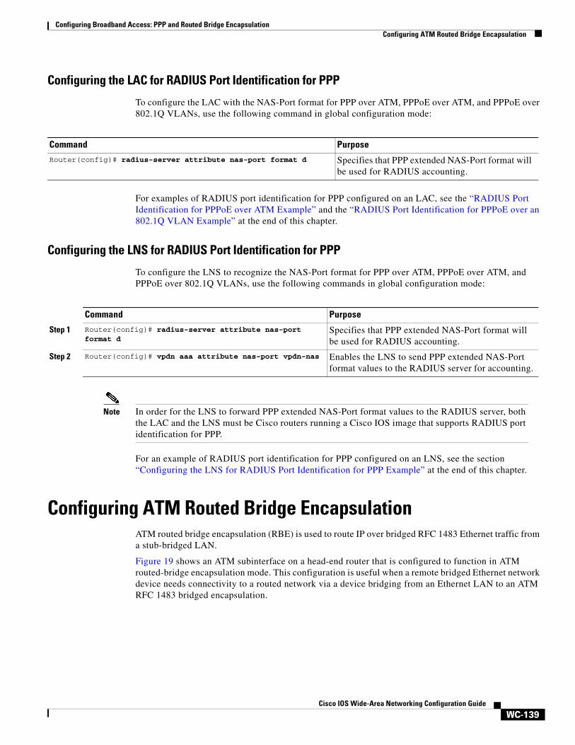
Configuring the LAC for RADIUS Port Identification for PPP
To configure the LAC with the NAS-Port format for PPP over ATM, PPPoE over ATM, and PPPoE over 802.1Q VLANs, use the following command in global configuration mode:
For examples of RADIUS port identification for PPP configured on an LAC, see the “RADIUS Port Identification for PPPoE over ATM Example” and the “RADIUS Port Identification for PPPoE over an 802.1Q VLAN Example” at the end of this chapter.
Configuring the LNS for RADIUS Port Identification for PPP
To configure the LNS to recognize the NAS-Port format for PPP over ATM, PPPoE over ATM, and PPPoE over 802.1Q VLANs, use the following commands in global configuration mode:
Note In order for the LNS to forward PPP extended NAS-Port format values to the RADIUS server, both the LAC and the LNS must be Cisco routers running a Cisco IOS image that supports RADIUS port identification for PPP.
For an example of RADIUS port identification for PPP configured on an LNS, see the section “Configuring the LNS for RADIUS Port Identification for PPP Example” at the end of this chapter.
Configuring ATM Routed Bridge EncapsulationATM routed bridge encapsulation (RBE) is used to route IP over bridged RFC 1483 Ethernet traffic from a stub-bridged LAN.
Figure 19 shows an ATM subinterface on a head-end router that is configured to function in ATM routed-bridge encapsulation mode. This configuration is useful when a remote bridged Ethernet network device needs connectivity to a routed network via a device bridging from an Ethernet LAN to an ATM RFC 1483 bridged encapsulation.
Command Purpose
Router(config)# radius-server attribute nas-port format d Specifies that PPP extended NAS-Port format will be used for RADIUS accounting.
Command Purpose
Step 1 Router(config)# radius-server attribute nas-port format d
Specifies that PPP extended NAS-Port format will be used for RADIUS accounting.
Step 2 Router(config)# vpdn aaa attribute nas-port vpdn-nas Enables the LNS to send PPP extended NAS-Port format values to the RADIUS server for accounting.

Configuring Broadband Access: PPP and Routed Bridge EncapsulationConfiguring ATM Routed Bridge Encapsulation
WC-140Cisco IOS Wide-Area Networking Configuration Guide
Figure 19 ATM Routed Bridge Encapsulation
Bridged IP packets received on an ATM interface configured in routed-bridge mode are routed via the IP header. Such interfaces take advantage of the characteristics of a stub LAN topology commonly used for DSL access and offer increased performance and flexibility over integrated routing and bridging (IRB).
Another benefit of ATM RBE is that it reduces the security risk associated with normal bridging or IRB by reducing the size of the nonsecured network. By using a single virtual circuit (VC) allocated to a subnet (which could be as small as a single IP address), ATM RBE uses an IP address in the subnet to limit the “trust environment” to the premises of a single customer.
ATM RBE does not support MAC-layer access lists; only IP access lists are supported.
ATM RBE does support Cisco Express Forwarding (CEF), fast switching, and process switching.
ATM RBE Subinterface Grouping by PVC RangeYou can configure ATM routed bridge encapsulation using an ATM PVC range rather than individual PVCs. When you configure a PVC range for routed bridge encapsulation, a point-to-point subinterface is created for each PVC in the range. The number of PVCs in a range can be calculated using the following formula:
number of PVCs = (end-vpi – start-vpi + 1) x (end-vci – start-vci +1)
Subinterface numbering begins with the subinterface on which the PVC range is configured and increases sequentially through the range.
Note You cannot explicitly configure the individual point-to-point subinterfaces created by the PVC range on a point-to-point subinterface. All the point-to-point subinterfaces in the range share the same configuration as the subinterface on which the PVC range is configured.
For further information on PVC ranges, see the section “Configuring an ATM PVC Range,” later in this chapter.
For an example of subinterface grouping by PVC range, see the section “ATM PVC Range on a Point-to-Point Subinterface Example” at the end of this chapter.
S47
63
ATM 4/0.100
172.31.5.9
Ethernet subnet172.31.5.0

Configuring Broadband Access: PPP and Routed Bridge EncapsulationConfiguring ATM Routed Bridge Encapsulation
WC-141Cisco IOS Wide-Area Networking Configuration Guide
ATM Routed Bridge Encapsulation Configuration Task ListTo configure ATM routed bridge encapsulation, perform the tasks in the following section. Each task is identified as required or optional.
• Configuring ATM Routed Bridge Encapsulation (Required)
• Verifying ATM Routed Bridge Encapsulation (Optional)
Configuring ATM Routed Bridge Encapsulation
To configure ATM RBE, use the following commands beginning in global configuration mode:
Only the specified network layer (IP) will be routed. Any remaining protocols can be passed on to bridging or other protocols. In this manner, ATM RBE can be used to route IP, while other protocols (such as IPX) are bridged normally.
For examples of ATM RBE, see the section “ATM Routed Bridge Encapsulation Configuration Examples” at the end of this chapter.
Verifying ATM Routed Bridge Encapsulation
To confirm that ATM RBE is enabled, use the show arp command and the show ip cache verbose command in EXEC mode:
Router# show arp
Protocol Address Age (min) Hardware Addr Type InterfaceInternet 10.1.0.51 6 0001.c9f2.a81d ARPA Ethernet3/1Internet 10.1.0.49 - 0060.0939.bb55 ARPA Ethernet3/1Internet 10.0.75.1 30 0010.0ba6.2020 ARPA Ethernet3/0Internet 10.8.101.35 6 00e0.1e8d.3f90 ARPA ATM1/0.4Internet 10.8.100.50 5 0007.144f.5d20 ARPA ATM1/0.2Internet 10.0.75.49 - 0060.0939.bb54 ARPA Ethernet3/0Internet 10.1.0.125 30 00b0.c2e9.bc55 ARPA Ethernet3/1#
Command Purpose
Step 1 Router(config)# interface atm slot/0.subinterface-number point-to-point
Specifies an ATM point-to-point subinterface.
Step 2 Router(config-subif)# pvc VPI/VCI
or
Router(config-subif)# range [range-name] pvc start-vpi/start-vci end-vpi/end-vci
Configures a PVC to carry the routed bridge traffic.
Configures a range of PVCs to carry the routed bridge traffic.
Step 3 Router(config-if-atm-vc)# exit
or
Router(config-if-atm-range)# exit
Exits to subinterface configuration mode.
Step 4 Router(config-subif)# atm route-bridge ip Enables the ATM Routed Bridge Encapsulation feature for IP.
Step 5 Router(config-subif)# ip address ip-address mask [secondary]
Provides an IP address on the same subnetwork as the remote network.
Step 6 Router(config-subif)# ^Z Exits to EXEC mode.
Configuring Broadband Access: PPP and Routed Bridge EncapsulationConfiguring an ATM PVC Range
WC-142Cisco IOS Wide-Area Networking Configuration Guide
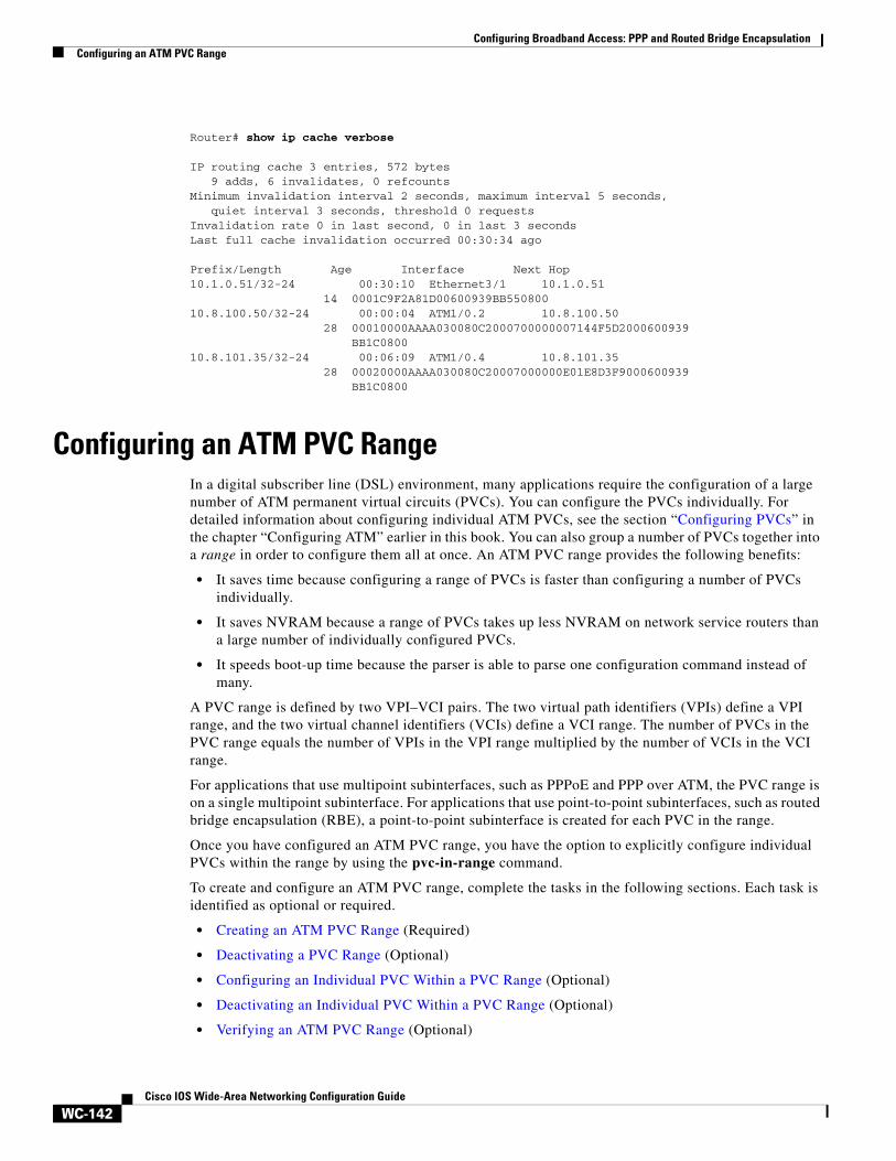
Router# show ip cache verbose
IP routing cache 3 entries, 572 bytes 9 adds, 6 invalidates, 0 refcountsMinimum invalidation interval 2 seconds, maximum interval 5 seconds, quiet interval 3 seconds, threshold 0 requestsInvalidation rate 0 in last second, 0 in last 3 secondsLast full cache invalidation occurred 00:30:34 ago
Prefix/Length Age Interface Next Hop10.1.0.51/32-24 00:30:10 Ethernet3/1 10.1.0.51 14 0001C9F2A81D00600939BB55080010.8.100.50/32-24 00:00:04 ATM1/0.2 10.8.100.50 28 00010000AAAA030080C2000700000007144F5D2000600939 BB1C080010.8.101.35/32-24 00:06:09 ATM1/0.4 10.8.101.35 28 00020000AAAA030080C20007000000E01E8D3F9000600939 BB1C0800
Configuring an ATM PVC RangeIn a digital subscriber line (DSL) environment, many applications require the configuration of a large number of ATM permanent virtual circuits (PVCs). You can configure the PVCs individually. For detailed information about configuring individual ATM PVCs, see the section “Configuring PVCs” in the chapter “Configuring ATM” earlier in this book. You can also group a number of PVCs together into a range in order to configure them all at once. An ATM PVC range provides the following benefits:
• It saves time because configuring a range of PVCs is faster than configuring a number of PVCs individually.
• It saves NVRAM because a range of PVCs takes up less NVRAM on network service routers than a large number of individually configured PVCs.
• It speeds boot-up time because the parser is able to parse one configuration command instead of many.
A PVC range is defined by two VPI–VCI pairs. The two virtual path identifiers (VPIs) define a VPI range, and the two virtual channel identifiers (VCIs) define a VCI range. The number of PVCs in the PVC range equals the number of VPIs in the VPI range multiplied by the number of VCIs in the VCI range.
For applications that use multipoint subinterfaces, such as PPPoE and PPP over ATM, the PVC range is on a single multipoint subinterface. For applications that use point-to-point subinterfaces, such as routed bridge encapsulation (RBE), a point-to-point subinterface is created for each PVC in the range.
Once you have configured an ATM PVC range, you have the option to explicitly configure individual PVCs within the range by using the pvc-in-range command.
To create and configure an ATM PVC range, complete the tasks in the following sections. Each task is identified as optional or required.
• Creating an ATM PVC Range (Required)
• Deactivating a PVC Range (Optional)
• Configuring an Individual PVC Within a PVC Range (Optional)
• Deactivating an Individual PVC Within a PVC Range (Optional)
• Verifying an ATM PVC Range (Optional)
Configuring Broadband Access: PPP and Routed Bridge EncapsulationConfiguring an ATM PVC Range
WC-143Cisco IOS Wide-Area Networking Configuration Guide
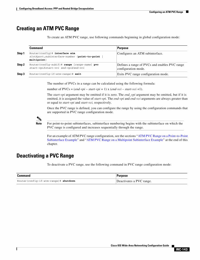
Creating an ATM PVC RangeTo create an ATM PVC range, use following commands beginning in global configuration mode:
The number of PVCs in a range can be calculated using the following formula:
number of PVCs = (end-vpi – start-vpi + 1) x (end-vci – start-vci +1).
The start-vpi argument may be omitted if it is zero. The end_vpi argument may be omitted, but if it is omitted, it is assigned the value of start-vpi. The end-vpi and end-vci arguments are always greater than or equal to start-vpi and start-vci, respectively.
Once the PVC range is defined, you can configure the range by using the configuration commands that are supported in PVC range configuration mode.
Note For point-to-point subinterfaces, subinterface numbering begins with the subinterface on which the PVC range is configured and increases sequentially through the range.
For an example of ATM PVC range configuration, see the sections “ATM PVC Range on a Point-to-Point Subinterface Example” and “ATM PVC Range on a Multipoint Subinterface Example” at the end of this chapter.
Deactivating a PVC Range To deactivate a PVC range, use the following command in PVC range configuration mode:
Command Purpose
Step 1 Router(config)# interface atm slot/port.subinterface-number {point-to-point | multipoint}
Configures an ATM subinterface.
Step 2 Router(config-subif)# range [range-name] pvc start-vpi/start-vci end-vpi/end-vci
Defines a range of PVCs and enables PVC range configuration mode.
Step 3 Router(config-if-atm-range)# exit Exits PVC range configuration mode.
Command Purpose
Router(config-if-atm-range)# shutdown Deactivates a PVC range.
Configuring Broadband Access: PPP and Routed Bridge EncapsulationConfiguring an ATM PVC Range
WC-144Cisco IOS Wide-Area Networking Configuration Guide
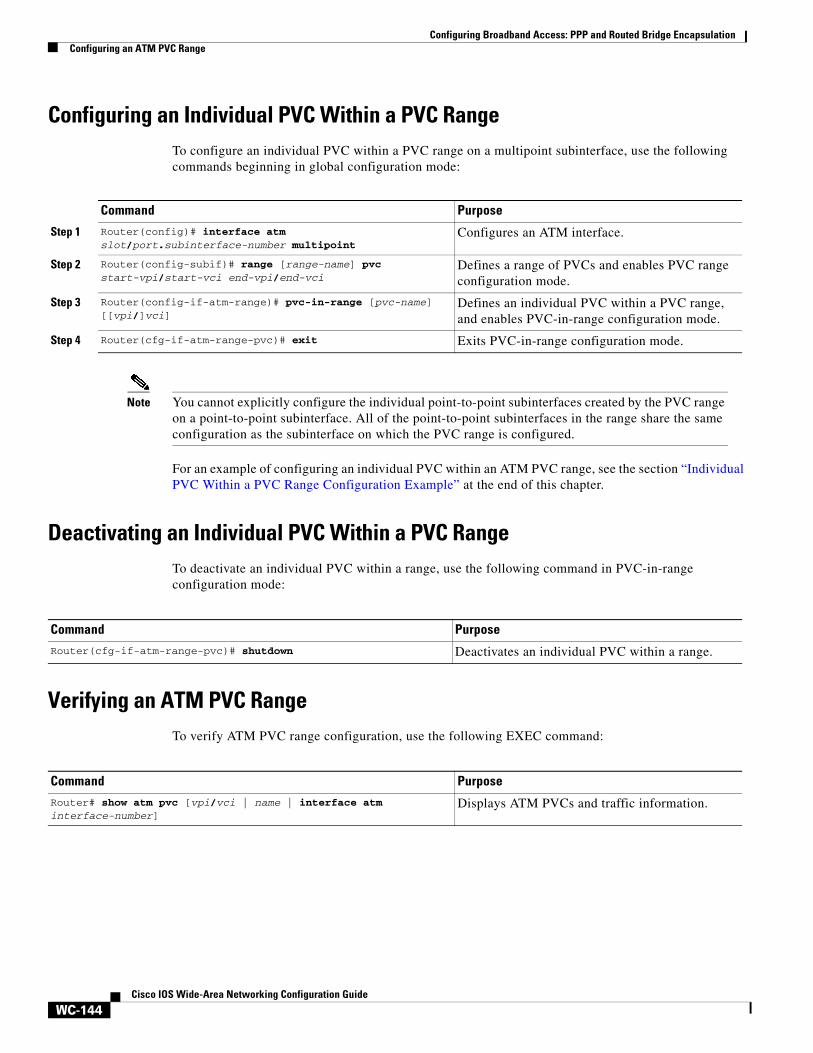
Configuring an Individual PVC Within a PVC RangeTo configure an individual PVC within a PVC range on a multipoint subinterface, use the following commands beginning in global configuration mode:
Note You cannot explicitly configure the individual point-to-point subinterfaces created by the PVC range on a point-to-point subinterface. All of the point-to-point subinterfaces in the range share the same configuration as the subinterface on which the PVC range is configured.
For an example of configuring an individual PVC within an ATM PVC range, see the section “Individual PVC Within a PVC Range Configuration Example” at the end of this chapter.
Deactivating an Individual PVC Within a PVC RangeTo deactivate an individual PVC within a range, use the following command in PVC-in-range configuration mode:
Verifying an ATM PVC Range To verify ATM PVC range configuration, use the following EXEC command:
Command Purpose
Step 1 Router(config)# interface atm slot/port.subinterface-number multipoint
Configures an ATM interface.
Step 2 Router(config-subif)# range [range-name] pvc start-vpi/start-vci end-vpi/end-vci
Defines a range of PVCs and enables PVC range configuration mode.
Step 3 Router(config-if-atm-range)# pvc-in-range [pvc-name] [[vpi/]vci]
Defines an individual PVC within a PVC range, and enables PVC-in-range configuration mode.
Step 4 Router(cfg-if-atm-range-pvc)# exit Exits PVC-in-range configuration mode.
Command Purpose
Router(cfg-if-atm-range-pvc)# shutdown Deactivates an individual PVC within a range.
Command Purpose
Router# show atm pvc [vpi/vci | name | interface atm interface-number]
Displays ATM PVCs and traffic information.
Configuring Broadband Access: PPP and Routed Bridge EncapsulationConfiguration Examples
WC-145Cisco IOS Wide-Area Networking Configuration Guide
Configuration Examples
The examples in the following sections illustrate how to configure the features described in this chapter. The examples are presented in the same order as the corresponding configuration task sections presented earlier in this chapter:
• PPP over ATM Configuration Examples
• PPPoE over ATM Configuration Example
• PPPoE over Ethernet Configuration Example
• PPPoE over an IEEE 802.1Q VLAN Configuration Example
• RADIUS Port Identification for PPP Configuration Examples
• ATM Routed Bridge Encapsulation Configuration Examples
• ATM PVC Range Configuration Examples
PPP over ATM Configuration ExamplesThis sections provides the following sets of examples for configuring PPP over ATM:
• IETF-Compliant MUX Encapsulated PPP over ATM Configuration Examples
• IETF-Compliant LLC Encapsulated PPP over ATM Configuration Examples
• Cisco Proprietary PPP-over-ATM Example
• PPP over an ATM SVC Configuration Example
IETF-Compliant MUX Encapsulated PPP over ATM Configuration Examples
This section provides the following examples for configuring IETF-compliant PPP over ATM:
• IIETF-Compliant PPP over ATM with Different Traffic-Shaping Parameters Example
• ADSL Termination Example
• Two Routers with Back-to-Back PVCs Example
• Multiplexed Encapsulation Using VC Class Example
IETF-Compliant PPP over ATM with Different Traffic-Shaping Parameters Example
PVCs with different PPP-over-ATM traffic-shaping parameters can be configured on the same subinterface. In the following example, three PVCs are configured for PPP over ATM on subinterface ATM 2/0.1. PVC 0/60 is configured with IETF-Compliant PPP over ATM encapsulation. Its traffic-shaping parameter is an unspecified bit rate with peak cell rate at 500 kbps. PVC 0/70 is also configured with IETF-Compliant PPP over ATM encapsulation, but its traffic-shaping parameter is non-real-time variable bit rate, with peak cell rate at 1 Mbps, sustainable cell rate at 500 kbps, and burst cell size of 64 cells. PVC 0/80 is configured with the Cisco-proprietary PPP over ATM encapsulation. Its traffic shaping parameter is an unspecified bit rate with peak cell rate at 700 kbps. For further information, refer to the section “Configuring IETF-Compliant MUX Encapsulated PPP over ATM PVCs” earlier in this chapter.
Router(config)# interface atm 2/0.1 multipointRouter(config-if)# pvc 0/60Router(config-if-atm-vc)# encapsulation aal5mux ppp virtual-template 3Router(config-if-atm-vc)# ubr 500

Configuring Broadband Access: PPP and Routed Bridge EncapsulationConfiguration Examples
WC-146Cisco IOS Wide-Area Networking Configuration Guide
Router(config-if-atm-vc)# exit
Router(config-if)# pvc 0/70Router(config-if-atm-vc)# encapsulation aal5mux ppp virtual-template 3Router(config-if-atm-vc)# vbr-nrt 1000 500 64Router(config-if-atm-vc)# exit
Router(config-if)# pvc 0/80Router(config-if-atm-vc)# encapsulation aal5ciscoppp virtual-template 3Router(config-if-atm-vc)# ubr 700Router(config-if-atm-vc)# exitRouter(config-if)#
ADSL Termination Example
The IETF-Compliant PPP over ATM feature was designed to support installations with ADSL circuits. Figure 20 illustrates a topology for ADSL termination. This topology allows you to establish a PPP connection to a Cisco 7200 series router.
The example also illustrates the use of PPP tunneling using L2TP to provide VPDN services, in this case for the domain cisco.com. Thus, a user who logs in as [email protected] is automatically tunneled to IP address 10.1.2.3. (See the chapter “Configuring Virtual Private Networks” in the Cisco IOS Dial Technologies Configuration Guides for details about setting up VPDN services.)
An example of the commands that you might enter for the user_router, dsl7200, and cisco-gateway (as shown in Figure 20) are described below. For further information, refer to the section “Configuring IETF-Compliant MUX Encapsulated PPP over ATM PVCs” earlier in this chapter.
Figure 20 ADSL Termination
user_router Configurationuser_router(config)# interface virtual-template 1user_router(config-if)# ip address negotiateduser_router(config-if)# ppp chap hostname [email protected]_router(config-if)# ppp chap password 0 ciscouser_router(config-if)# exit
dsl7200 cisco-gatewayATM switchDSLAM
User
1271
1
user_router
User
IP

Configuring Broadband Access: PPP and Routed Bridge EncapsulationConfiguration Examples
WC-147Cisco IOS Wide-Area Networking Configuration Guide
user_router(config)# interface atm 0user_router(config-if)# pvc 0/40user_router(config-if-atm-vc)# encapsulation aal5mux ppp virtual-template 1user_router(config-if-atm-vc)# exituser_router(config-if)# exituser_router(config)#
dsl7200 Configurationdsl7200(config)# username [email protected] password 0 ciscodsl7200(config)# username dsl7200 password 0 cisco
dsl7200(config)# vpdn enable
dsl7200(config)# vpdn-group 1dsl7200(config)# request dialin l2tp ip 10.2.1.1 domain cisco.com
dsl7200(config)# interface virtual-template 1dsl7200(config-if)# ppp authentication chapdsl7200(config-if)# exit
dsl7200(config)# interface atm 2/0dsl7200(config-if)# pvc 0/40dsl7200(config-if-atm-vc)# encapsulation aal5mux ppp virtual-template 1dsl7200(config-if-atm-vc)# exitdsl7200(config-if)# exitdsl7200(config)#
cisco-gateway Configurationcisco_gateway(config)# username cisco_gateway password 0 ciscocisco_gateway(config)# username [email protected] password 0 cisco
cisco_gateway(config)# vpdn enable
cisco_gateway(config)# vpdn-group 1cisco_gateway(config)# accept dialin l2tp virtual-template 1 remote dsl7200
cisco_gateway(config)# interface loopback 0cisco_gateway(config-if)# ip address 10.0.1.1 255.255.255.0cisco_gateway(config-if)# exit
cisco_gateway(config)# interface virtual-template 1cisco_gateway(config-if)# ip unnumbered loopback 0cisco_gateway(config-if)# peer default ip address pool pool-1cisco_gateway(config-if)# exit
cisco_gateway(config)# ip local pool pool-1 10.1.2.1 10.1.2.254
Two Routers with Back-to-Back PVCs Example
Figure 21 illustrates an ATM interface with two PPP sessions over two PVC session connections. (See the chapter “PPP Configuration” in the Cisco IOS Dial Technologies Configuration Guide for details on PPP configuration.) The sample commands following Figure 21 establish the back-to-back router configuration. For further information, refer to the section “Configuring IETF-Compliant MUX Encapsulated PPP over ATM PVCs” earlier in this chapter.

Configuring Broadband Access: PPP and Routed Bridge EncapsulationConfiguration Examples
WC-148Cisco IOS Wide-Area Networking Configuration Guide
Figure 21 Two Routers with Back-to-Back PVCs
R1 ConfigurationRouter1(config)# interface atm 2/0Router1(config-if)# atm clock internalRouter1(config-if)# pvc 0/60Router1(config-if-atm-vc)# encapsulation aal5mux ppp virtual-template 1Router1(config-if-atm-vc)# ubr 90Router1(config-if-atm-vc)# exit
Router1(config-if)# pvc 0/70Router1(config-if-atm-vc)# encapsulation aal5mux ppp virtual-template 2Router1(config-if-atm-vc)# vbr-nrt 90 50 1024Router1(config-if-atm-vc)# exit
Router1(config-if)# interface virtual-template 1Router1(config-if)# ip address 10.0.1.1 255.255.255.0
Router1(config-if)# interface virtual-template 2Router1(config-if)# ip address 10.0.2.1 255.255.255.0Router1(config-if)# exitRouter1(config)#
R2 ConfigurationRouter2(config)# interface atm 2/0.1 multipointRouter2(config-if)# pvc 0/60Router2(config-if-atm-vc)# encapsulation aal5mux ppp virtual-template 1Router2(config-if-atm-vc)# ubr 90Router2(config-if-atm-vc)# exit
Router2(config-if)# pvc 0/70Router2(config-if-atm-vc)# encapsulation aal5mux ppp virtual-template 2Router2(config-if-atm-vc)# vbr-nrt 90 50 1024Router2(config-if-atm-vc)# exitRouter2(config-if)# exit
Router2(config)# interface virtual-template 1Router2(config-if)# ip address 10.0.1.2 255.255.255.0Router2(config-if)# exit
Router2(config)# interface virtual-template 2Router2(config-if)# ip address 10.0.2.2 255.255.255.0
Multiplexed Encapsulation Using VC Class Example
In the following example, PVC 0/60 is configured on subinterface ATM 2/0.1 with a VC class attached to it. For details on creating and applying a VC class, see the section “Configuring VC Classes” in the chapter “Configuring ATM.” By rule of inheritance, PVC 0/60 runs with IETF-Compliant PPP over ATM encapsulation using the configuration from interface virtual-template 1. Its parameter is an unspecified bit rate with peak cell at 90 kbps.
Router(config)# interface atm 2/0.1Router(config-if)# pvc 0/60
R2R1
10.0.1.1
10.0.2.1
10.0.1.2
10.0.2.2
VC 60
VC 70 1271
2
Configuring Broadband Access: PPP and Routed Bridge EncapsulationConfiguration Examples
WC-149Cisco IOS Wide-Area Networking Configuration Guide
Router(config-if-atm-vc)# class-vc pvc-pppRouter(config-if-atm-vc)# exitRouter(config-if)# exit
Router(config)# vc-class atm pvc-pppRouter(config-vc-class)# encapsulation aal5mux ppp virtual-template 1Router(config-vc-class)# ubr 90Router(config-vc-class)# exitRouter(config)#
IETF-Compliant LLC Encapsulated PPP over ATM Configuration Examples
This section provides the following examples for configuring IETF-compliant LLC encapsulated PPP over ATM:
• Configuring IETF-Compliant PPP over ATM LLC Encapsulation Example
• Overriding a Virtual Template for IETF-Compliant PPP over ATM Example
• Disabling IETF-Compliant PPP over ATM LLC Encapsulation on a Specific VC Example
Configuring IETF-Compliant PPP over ATM LLC Encapsulation Example
This example shows how to configure IETF PPP over ATM LLC Encapsulation in the VC class called “ppp-default.” The VC class specifies virtual template 1 from which to spawn PPP interfaces, snap encapsulation (the default), and a UBR class traffic type at 256 kbps. When the VC class “ppp-default” is configured on interface 0.1, PVC 0/70 inherits these properties. PVC 0/80 overrides virtual template 1 in the VC class and uses virtual template 2 instead. PVC 0/90 also overrides virtual template 1 and uses virtual template 3 instead. In addition, PVC 0/90 uses a VC multiplexed encapsulation and a UBR class traffic type at 500 kbps. For further information, refer to the section “Configuring IETF-Compliant LLC Encapsulated PPP over ATM PVCs” earlier in this chapter.
Router(config)# interface atm 0.1 multipointRouter(config-if)# class-int ppp-default!Router(config-if)# pvc 0/70Router(config-if-atm-vc)# exit!Router(config-if)# pvc 0/80Router(config-if-atm-vc)# protocol ppp virtual-template 2Router(config-if-atm-vc)# exit!Router(config-if)# pvc 0/90Router(config-if-atm-vc)# encapsulation aal5mux ppp virtual-template 3Router(config-if-atm-vc)# ubr 500Router(config-if-atm-vc)# exitRouter(config-if)# exit!Router(config)# vc-class atm ppp-defaultRouter(config-vc-class)# protocol ppp virtual-template 1Router(config-vc-class)# ubr 256Router(config-vc-class)# exitRouter(config)#
Overriding a Virtual Template for IETF-Compliant PPP over ATM Example
This example illustrates how to use inheritance to override a virtual template configuration for mux ppp or ciscoppp encapsulation options. For PVC 5/505, since the encapsulation option at that level is ciscoppp virtual template 1, as specified in the VC class called “muxppp,” the protocol ppp
Configuring Broadband Access: PPP and Routed Bridge EncapsulationConfiguration Examples
WC-150Cisco IOS Wide-Area Networking Configuration Guide
virtual-template 2 command overrides only the virtual-template configuration. For further information, refer to the section “Configuring IETF-Compliant LLC Encapsulated PPP over ATM PVCs” earlier in this chapter.
Router(config)# interface atm 2/0Router(config-if)# class-int muxppp!Router(config-if)# pvc 5/505Router(config-if-atm-vc)# protocol ppp virtual-template 2Router(config-if-atm-vc)# exit!Router(config)# vc-class muxpppRouter(config-vc-class)# encapsulation aal5ciscoppp virtual-template 1Router(config-vc-class)# exitRouter(config)#
Disabling IETF-Compliant PPP over ATM LLC Encapsulation on a Specific VC Example
This example shows how to limit the configuration of a particular LLC encapsulated protocol to a particular VC. First, we see that the VC class called “ppp” is configured with IETF PPP over ATM with LLC encapsulation and virtual template 1. This VC class is then applied to ATM interface 1/0/0. By configuring snap encapsulation by itself on PVC 0/32, you disable IETF PPP over ATM with LLC encapsulation on this particular PVC; PVC 0/32 will only carry IP. For further information, refer to the section “Configuring IETF-Compliant LLC Encapsulated PPP over ATM PVCs” earlier in this chapter.
Router(config)# interface atm 1/0/0Router(config-if)# class-int pppRouter(config-if)# exit!Router(config)# interface atm 1/0/0.100 point-to-pointRouter(config-if)# description IP only VCRouter(config-if)# ip address 10.1.1.1 255.255.255.0Router(config-if)# pvc 0/32Router(config-if-atm-vc)# encapsulation aal5snapRouter(config-if-atm-vc)# exitRouter(config-if)# exit!Router(config)# vc-class atm pppRouter(config-vc-class)# encapsulation aal5snapRouter(config-vc-class)# protocol ppp virtual-template 1Router(config-vc-class)# exitRouter(config)#
Cisco Proprietary PPP-over-ATM Example
The following example shows how to configure Cisco Proprietary PPP over ATM to use PPP unnumbered link and Challenge Handshake Authentication Protocol (CHAP) authentication. For further information, refer to the sections “Configuring PPP over ATM” and “Configuring Cisco-Proprietary PPP over ATM PVCs” earlier in this chapter.
configure terminal!interface virtual-template 2encapsulation pppip unnumbered ethernet 0/0ppp authentication chap
!interface atm 2/0.2 point-to-pointpvc 0/34encapsulation aal5ciscoppp virtual-template 2exit

Configuring Broadband Access: PPP and Routed Bridge EncapsulationConfiguration Examples
WC-151Cisco IOS Wide-Area Networking Configuration Guide
PPP over an ATM SVC Configuration Example
In the following example, ATM interface 2/0/0 is configured to accept ATM SVC calls whose called party address is 47.00918100000000400B0A2501.0060837B4740.00. The same ATM NSAP address can be configured on other physical ATM interfaces as well. When a PPP session is established, a virtual access interface is created and cloned with the configuration from virtual template 1. All PPP sessions established on this ATM interface will use the IP address of loopback interface 0. A maximum of 100 SVCs can be established using this configuration. SVCs established using this configuration cannot take up more than 50 Mbps in total bandwidth.
interface ATM 2/0/0svc annaencapsulation aal5autoprotocol ppp virtual-template 1max vc 100max bandwidth 50000
atm nsap 47.00918100000000400B0A2501.0060837B4740.00!interface virtual-template 1ip unnumbered loopback 0
!interface loopback 0ip address 10.7.1.1 255.255.255.0
PPPoE over ATM Configuration ExampleThe following example configures PPPoE over ATM to accept dial-in PPPoE sessions. The virtual access interface for the PPP session is cloned form virtual template interface 1. On subinterface ATM 2/0.1, ATM PVC with VPI 0 and VCI 60 is configured with Logical Link Control (LLC)/Subnetwork Access Protocol (SNAP) encapsulation and is configured to run PPPoE. Bridged Ethernet protocol data units (PDUs) with destination MAC address set to the ATM interface MAC address and Ethernet type set to 0x8863 for that PVC are enqueued to the PPPoE discovery process. All bridged Ethernet PDUs with destination MAC address set to the ATM interface MAC address and Ethernet type set to 0x8864 coming in from that PVC are forwarded to the virtual access interface associated with the PPP session.
vpdn enable
vpdn-group 1 accept dialin protocol pppoe virtual-template 1
interface atm 2/0.1 multipoint pvc 0/60 encapsulation aal5snap protocol pppoe
interface virtual-template 1 ip addr 10.0.1.2 255.255.255.0
mtu 1492
For PPPoE virtual template interfaces, “mtu 1492” must be configured because Ethernet has a maximum payload size of 1500 bytes, the PPPoE header is 6 bytes, and PPP Protocol ID is 2 bytes.
Note Dial-out mode will not be supported.
Configuring Broadband Access: PPP and Routed Bridge EncapsulationConfiguration Examples
WC-152Cisco IOS Wide-Area Networking Configuration Guide
PPPoE over Ethernet Configuration ExampleThe following example configures PPPoE on Ethernet to accept dial-in PPPoE sessions. The virtual access interface for the PPP session is cloned from virtual template interface 1. Bridged Ethernet protocol data units (PDUs) with destination MAC addresses set to the Ethernet interface MAC address and Ethernet type set to 0x8863 are enqueued to the PPPoE discovery process. All bridged Ethernet PDUs with destination MAC addresses set to the Ethernet interface MAC address and Ethernet type set to 0x8864 coming in are forwarded to the virtual access interface associated with the PPP session.
interface ethernet1/0 pppoe enable
!vpdn enable!vpdn-group 1accept dialinprotocol pppoevirtual template 1
pppoe limit per-mac 90!interface virtual-template 1ip address 100.100.100.100 255.255.255.0mtu 1492
For PPPoE virtual template interfaces, the mtu command must be configured because Ethernet has a maximum payload size of 1500 bytes, the PPPoE header is 6 bytes, and PPP Protocol ID is 2 bytes.
Note Dial-out mode will not be supported.
PPPoE over an IEEE 802.1Q VLAN Configuration ExampleThe following example shows the configuration of PPPoE over an 802.1Q encapsulated VLAN:
interface FastEthernet0/0.10encapsulation dot1Q 10pppoe enable
!vpdn enableno vpdn logging!vpdn-group 1accept dialinprotocol pppoevirtual-template 1
pppoe limit per-vlan 200!interface virtual-template 1ip address 100.100.100.100 255.255.255.0mtu 1492
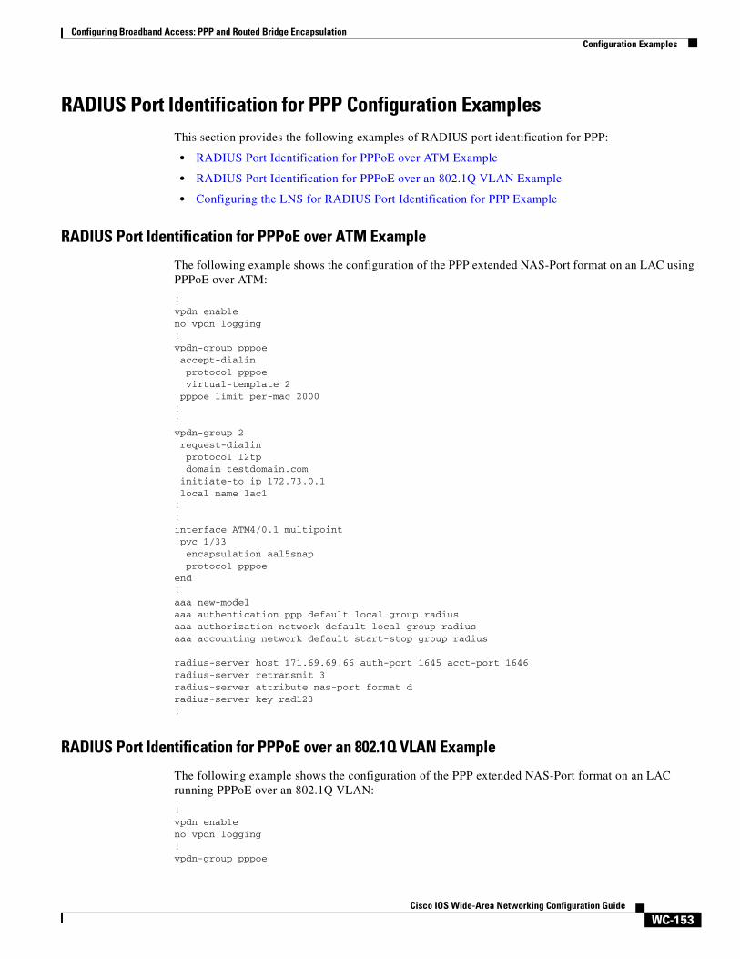
Configuring Broadband Access: PPP and Routed Bridge EncapsulationConfiguration Examples
WC-153Cisco IOS Wide-Area Networking Configuration Guide
RADIUS Port Identification for PPP Configuration ExamplesThis section provides the following examples of RADIUS port identification for PPP:
• RADIUS Port Identification for PPPoE over ATM Example
• RADIUS Port Identification for PPPoE over an 802.1Q VLAN Example
• Configuring the LNS for RADIUS Port Identification for PPP Example
RADIUS Port Identification for PPPoE over ATM Example
The following example shows the configuration of the PPP extended NAS-Port format on an LAC using PPPoE over ATM:
!vpdn enableno vpdn logging!vpdn-group pppoe accept-dialin protocol pppoe virtual-template 2 pppoe limit per-mac 2000!!vpdn-group 2 request-dialin protocol l2tp domain testdomain.com initiate-to ip 172.73.0.1 local name lac1!!interface ATM4/0.1 multipoint pvc 1/33 encapsulation aal5snap protocol pppoeend!aaa new-modelaaa authentication ppp default local group radiusaaa authorization network default local group radiusaaa accounting network default start-stop group radius
radius-server host 171.69.69.66 auth-port 1645 acct-port 1646radius-server retransmit 3radius-server attribute nas-port format dradius-server key rad123!
RADIUS Port Identification for PPPoE over an 802.1Q VLAN Example
The following example shows the configuration of the PPP extended NAS-Port format on an LAC running PPPoE over an 802.1Q VLAN:
!vpdn enableno vpdn logging!vpdn-group pppoe

Configuring Broadband Access: PPP and Routed Bridge EncapsulationConfiguration Examples
WC-154Cisco IOS Wide-Area Networking Configuration Guide
accept-dialin protocol pppoe virtual-template 2 pppoe limit per-mac 2 pppoe limit per-vlan 10!vpdn-group 2 request-dialin protocol l2tp domain testdomain.com initiate-to ip 172.73.0.1 local name lac1!interface FastEthernet2/0.2 encapsulation dot1Q 2 pppoe enable!interface FastEthernet2/0.3 encapsulation dot1Q 3 pppoe enable!aaa new-modelaaa authentication ppp default local group radiusaaa authorization network default local group radiusaaa accounting network default start-stop group radius
radius-server host 171.69.69.66 auth-port 1645 acct-port 1646radius-server retransmit 3radius-server attribute nas-port format dradius-server key rad123
Configuring the LNS for RADIUS Port Identification for PPP Example
In the following example, the LNS is configured to recognize and forward PPP extended NAS-Port format values to the RADIUS server. The PPP extended NAS-Port format must also be configured on the LAC for this configuration to be effective.
vpdn enableno vpdn logging!vpdn-group L2TP-tunnel accept-dialin protocol l2tp virtual-template 1 terminate-from hostname lac1 local name lns1! !aaa new-modelaaa authentication ppp default local group radiusaaa authorization network default local group radiusaaa accounting network default start-stop group radius
radius-server host 171.79.79.76 auth-port 1645 acct-port 1646radius-server retransmit 3radius-server attribute nas-port format dradius-server key lns123!vpdn aaa attribute nas-port vpdn-nas

Configuring Broadband Access: PPP and Routed Bridge EncapsulationConfiguration Examples
WC-155Cisco IOS Wide-Area Networking Configuration Guide
ATM Routed Bridge Encapsulation Configuration ExamplesThis section provides the following configuration examples:
• ATM Routed Bridge Encapsulation Example
• ATM Routed Bridge Encapsulation on an Unnumbered Interface Example
• Concurrent Bridging and ATM Routed Bridge Encapsulation Example
ATM Routed Bridge Encapsulation Example
The following example shows a typical ATM routed bridge encapsulation configuration:
interface atm 4/0.100 point-to-pointip address 172.16.5.9 255.255.255.0pvc 0/32atm route-bridge ip
ATM Routed Bridge Encapsulation on an Unnumbered Interface Example
The following example uses a static route to point to an unnumbered interface:
interface loopback 0 ip address 172.16.5.1 255.255.255.0
interface atm 4/0.100 point-to-point ip unnumbered loopback 0 pvc 0/32 atm route-bridge ip!ip route 172.16.5.2 255.255.255.255 atm 4/0.100
Concurrent Bridging and ATM Routed Bridge Encapsulation Example
The following example shows concurrent use of ATM routed bridge encapsulation with normal bridging. IP datagrams are route-bridged, and other protocols (such as IPX or AppleTalk) are bridged.
bridge 1 protocol ieee
interface atm 4/0.100 point-to-pointip address 172.16.5.9 255.255.255.0pvc 0/32bridge-group 1atm route-bridge ip
ATM PVC Range Configuration ExamplesThis section provides the following examples of ATM PVC Range configuration:
• ATM PVC Range on a Point-to-Point Subinterface Example
• ATM PVC Range on a Multipoint Subinterface Example
• Individual PVC Within a PVC Range Configuration Example

Configuring Broadband Access: PPP and Routed Bridge EncapsulationConfiguration Examples
WC-156Cisco IOS Wide-Area Networking Configuration Guide
ATM PVC Range on a Point-to-Point Subinterface Example
In the following example, a PVC range called “range1” is created with a total of 100 PVCs in the range. A point-to-point subinterface will be created for each PVC in the range. Routed bridge encapsulation is configured on this range.
Router(config)# interface atm 6/0.200 point-to-pointRouter(config-subif)# ip unnumbered loopback 1Router(config-subif)# atm route-bridged ipRouter(config-subif)# range range1 pvc 1/200 1/299Router(config-if-atm-range)# end
ATM PVC Range on a Multipoint Subinterface Example
In the following example, a PVC range called “range-pppoa-1” is created with a total of 500 PVCs in the range. PVC parameters are configured for the range, including the assignment of a VC class called “classA.”
router(config)# interface atm 6/0.110 multipointrouter(config-subif)# range range-pppoa-1 pvc 100 4/199router(config-if-atm-range)# class-range classArouter(config-if-atm-range)# ubr 1000router(config-if-atm-range)# encapsulation aal5snaprouter(config-if-atm-range)# protocol ppp virtual-template 2
Individual PVC Within a PVC Range Configuration Example
In the following example, “pvc1” within the PVC range called “range1” is deactivated.
router(config)# interface atm 6/0.110 multipointrouter(config-subif)# range range1 pvc 100 4/199router(config-if-atm-range)# class-range classArouter(config-if-atm-range)# pvc-in-range pvc1 3/104router(cfg-if-atm-range-pvc)# shutdown