configuring frame relay - cisco.com · configuring frame relay feature history release modification...
TRANSCRIPT

Configuring Frame Relay
Feature History
ModificationRelease
For information about feature support in Cisco IOSsoftware, use Cisco Feature Navigator.
Cisco IOS
• Finding Feature Information, page 1
• Information About Frame Relay, page 1
• How to Configure Frame Relay, page 25
• Configuration Examples for Frame Relay, page 58
• Additional References, page 80
Finding Feature InformationYour software release may not support all the features documented in this module. For the latest caveats andfeature information, see Bug Search Tool and the release notes for your platform and software release. Tofind information about the features documented in this module, and to see a list of the releases in which eachfeature is supported, see the feature information table at the end of this module.
Use Cisco Feature Navigator to find information about platform support and Cisco software image support.To access Cisco Feature Navigator, go to www.cisco.com/go/cfn. An account on Cisco.com is not required.
Information About Frame Relay
Cisco Frame Relay MIBThe Cisco Frame Relay MIB adds extensions to the standard Frame Relay MIB (RFC 1315). It providesadditional link-level and virtual circuit (VC)-level information and statistics that are mostly specific to Cisco
Wide-Area Networking Configuration Guide: Frame Relay, Cisco IOS Release 15S 1

FrameRelay implementation. ThisMIB provides SNMP networkmanagement access tomost of the informationcovered by the show frame-relaycommands such as, show frame-relay lmi, show frame-relay pvc, showframe-relay map, and show frame-relay svc.
Frame Relay Hardware ConfigurationsYou can create Frame Relay connections using one of the following hardware configurations:
• Routers and access servers connected directly to the Frame Relay switch
• Routers and access servers connected directly to a channel service unit/digital service unit (CSU/DSU),which then connects to a remote Frame Relay switch
Routers can connect to Frame Relay networks either by direct connection to a Frame Relay switch orthrough CSU/DSUs. However, a single router interface configured for Frame Relay can be configuredfor only one of these methods.
Note
The CSU/DSU converts V.35 or RS-449 signals to the properly coded T1 transmission signal for successfulreception by the Frame Relay network. The figure below illustrates the connections among the components.
Figure 1: Typical Frame Relay Configuration
The Frame Relay interface actually consists of one physical connection between the network server and theswitch that provides the service. This single physical connection provides direct connectivity to each deviceon a network.
Frame Relay EncapsulationFrame Relay supports encapsulation of all supported protocols in conformance with RFC 1490,MultiprotocolInterconnect over Frame Relay, allowing interoperability among multiple vendors. Use the IETF form ofFrame Relay encapsulation if your device or access server is connected to another vendor’s equipment acrossa Frame Relay network. IETF encapsulation is supported either at the interface level or on a per-VC basis.
Shut down the interface prior to changing encapsulation types. Although shutting down the interface is notrequired, it ensures that the interface is reset for the new encapsulation.
Wide-Area Networking Configuration Guide: Frame Relay, Cisco IOS Release 15S2
Configuring Frame RelayFrame Relay Hardware Configurations

Dynamic or Static Address Mapping
Dynamic Address MappingDynamic address mapping uses Frame Relay Inverse Address Resolution Protocol (ARP) to request thenext-hop protocol address for a specific connection, given its known Data link connection identifier (DLCI).Responses to Inverse ARP requests are entered in an address-to-DLCI mapping table on the device or accessserver. The DLCImapping table is then used to supply the next-hop protocol address or the DLCI for outgoingtraffic.
Inverse ARP is enabled by default for all protocols it supports. However, it can be disabled for specificprotocol-DLCI pairs. As a result, you can use dynamic mapping for some protocols and static mapping forother protocols on the same DLCI. You can explicitly disable Inverse ARP for a protocol-DLCI pair if youknow that the protocol is not supported on the other end of the connection. For more information, see theDisabling or Reenabling Frame Relay Inverse ARP section.
Because Inverse ARP is enabled by default, no additional command is required to configure dynamicmapping on an interface and packets are not sent out for protocols that are not enabled on the interface.
Note
Static Address MappingA static map links a specified next-hop protocol address to a specified Data link connection identifier (DLCI).Static mapping removes the need for Inverse Address Resolution Protocol (ARP) requests; when you supplya static map, Inverse ARP is automatically disabled for the specified protocol on the specified DLCI. Youmust use static mapping in the any of the following scenarios:
• If the device at the other end does not support Inverse ARP at all
• If the device does not support Inverse ARP for a specific protocol that you want to use over Frame Relay.
You can simplify the configuration for the Open Shortest Path First (OSPF) protocol by adding the optionalbroadcast keyword when doing this task. Refer to the frame-relay map command description in the CiscoIOS Wide-Area Networking Command Reference and the examples at the end of this chapter for moreinformation about using the broadcast keyword.
LMIThe software supports LocalManagement Interface (LMI) autosense, which enables the interface to determinethe LMI type supported by the switch. Support for LMI autosense means that you are no longer required toconfigure the LMI explicitly.
LMI autosense is active in the following situations:
• The router is powered up or the interface changes state to up.
• The line protocol is down but the line is up.
• The interface is a Frame Relay DTE.
Wide-Area Networking Configuration Guide: Frame Relay, Cisco IOS Release 15S 3
Configuring Frame RelayDynamic or Static Address Mapping

• The LMI type is not explicitly configured.
Activating LMI Autosense
Status Request
When LMI autosense is active, it sends out a full status request, in all three LMI types, to the switch. Theorder is ANSI, ITU, cisco, but it is done in rapid succession. software provides the ability to listen in on bothDLCI 1023 (cisco LMI) and DLCI 0 (ANSI and ITU) simultaneously.
Status Messages
One or more of the status requests will prompts a reply (status message) from the switch. The device decodesthe format of the reply and configures itself automatically. If more than one reply is received, the deviceconfigures itself with the type of the last received reply. This is to accommodate intelligent switches that canhandle multiple formats simultaneously.
LMI Autosense
If Local Management Interface (LMI) autosense is unsuccessful, an intelligent retry scheme is built in. EveryN391 interval (default is 60 seconds, which is 6 keep exchanges at 10 seconds each), LMI autosense attemptsto ascertain the LMI type. For more information about N391, see the frame-relay lmi-n391dte command inthe chapter "Frame Relay Commands " in the Cisco IOS Wide-Area Networking Command Reference .
The only visible indication to the user that LMI autosense is in progress is that debug frame lmi is enabled.At every N391 interval, the user sees 3 rapid status inquiries from the serial interface one in each of thefollowing LMI-type:
• ANSI
• ITU
• Cisco
Configuration Options
No configuration options are provided; LMI autosense is transparent to the user. You can turn off LMIautosense by explicitly configuring an LocalManagement Interface (LMI) type. The LMI type must be writteninto NVRAM so that next time the device powers up, LMI autosense will be inactive. At the end of autoinstall,a frame-relay lmi-type xxx statement is included within the interface configuration. This configuration is notautomatically written to NVRAM; you must explicitly write the configuration to NVRAM by using the copysystem:running-config or copy nvram:startup-config command.
Frame Relay SVCsAccess to Frame Relay networks is made through private leased lines at speeds ranging from 56 kbps to 45Mbps. FrameRelay is a connection-oriented packet-transfermechanism that establishesVCs between endpoints.
Wide-Area Networking Configuration Guide: Frame Relay, Cisco IOS Release 15S4
Configuring Frame RelayFrame Relay SVCs

Switched virtual circuits (SVCs) allow access through a Frame Relay network by setting up a path to thedestination endpoints only when the need arises and tearing down the path when it is no longer needed.
SVCs can coexist with PVCs in the same sites and routers. For example, routers at remote branch officesmight set up PVCs to the central headquarters for frequent communication, but set up SVCs with each otheras needed for intermittent communication. As a result, any-to-any communication can be set up withoutany-to-any PVCs.
On SVCs, quality of service (QoS) elements can be specified on a call-by-call basis to request networkresources.
SVC support is offered in the Enterprise image on Cisco platforms that include a serial or HSSI interface.
You must have the following services before Frame Relay SVCs can operate:
• Frame Relay SVC support by the service provider--The service provider’s switch must be capable ofsupporting SVC operation.
• Physical loop connection--A leased line or dedicated line must exist between the router (DTE) and thelocal Frame Relay switch.
Operating SVCsSVC operation requires that the Data Link layer (Layer 2) be set up, running ITU-T Q.922 Link AccessProcedures to Frame mode bearer services (LAPF), prior to signalling for an SVC. Layer 2 sets itself up assoon as SVC support is enabled on the interface, if both the line and the line protocol are up. When the SVCsare configured and demand for a path occurs, the Q.933 signalling sequence is initiated. Once the SVC is setup, data transfer begins.
Q.922 provides a reliable link layer for Q.933 operation. All Q.933 call control information is transmittedover DLCI 0; this DLCI is also used for the management protocols specified in ANSI T1.617 Annex D orQ.933 Annex A.
You must enable SVC operation at the interface level. Once it is enabled at the interface level, it is enabledon any subinterfaces on that interface. One signalling channel, DLCI 0, is set up for the interface, and allSVCs are controlled from the physical interface.
Frame Relay Traffic ShapingTraffic shaping applies to both PVCs and SVCs. Enabling Frame Relay traffic shaping on an interface enablesboth traffic shaping and per-VC queueing on all the PVCs and SVCs on the interface. Traffic shaping enablesthe router to control the circuit’s output rate and react to congestion notification information if also configured.
Frame Relay traffic shaping is not effective for Layer 2 PVC switching using the frame-relay routecommand.
Note
Defining VCs for Different Types of TrafficBy defining separate VCs for different types of traffic and specifying queueing and an outbound traffic ratefor each VC, you can provide guaranteed bandwidth for each type of traffic. By specifying different trafficrates for different VCs over the same line, you can perform virtual time division multiplexing. By throttling
Wide-Area Networking Configuration Guide: Frame Relay, Cisco IOS Release 15S 5
Configuring Frame RelayFrame Relay Traffic Shaping

outbound traffic from high-speed lines in central offices to lower-speed lines in remote locations, you canease congestion and data loss in the network; enhanced queueing also prevents congestion-caused data loss.
Frame Relay ForeSightForeSight is the network traffic control software used in some Cisco switches. The Cisco Frame Relay switchcan extend ForeSight messages over a User-to-Network Interface (UNI), passing the backward congestionnotification for VCs.
ForeSight allows Cisco Frame Relay routers to process and react to ForeSight messages and adjust VC leveltraffic shaping in a timely manner.
ForeSight must be configured explicitly on both the Cisco router and the Cisco switch. ForeSight is enabledon the Cisco router when Frame Relay traffic shaping is configured. However, the router’s response to ForeSightis not applied to any VC until the frame-relay adaptive-shaping foresight command is added to the VCsmap-class.When ForeSight is enabled on the switch, the switch will periodically send out a ForeSight messagebased on the time value configured. The time interval can range from 40 to 5000 milliseconds.
When a Cisco router receives a ForeSight message indicating that certain DLCIs are experiencing congestion,the Cisco router reacts by activating its traffic-shaping function to slow down the output rate. The router reactsas it would if it were to detect the congestion by receiving a packet with the backward explicit congestionnotification (BECN) bit set.
When ForeSight is enabled, Frame Relay traffic shaping will adapt to ForeSight messages and BECNmessages.
Frame Relay ForeSight Prerequisites
For router ForeSight to work, the following conditions must exist on the Cisco router:
• Frame Relay traffic shaping must be enabled on the interface.
• The traffic shaping for a circuit is adapted to ForeSight.
The following additional condition must exist on the Cisco switch:
• The UNI connecting to the router is Consolidated Link Layer Management (CLLM) enabled, with theproper time interval specified.
Frame Relay router ForeSight is enabled automatically when you use the frame-relay traffic-shapingcommand. However, you must issue themap-class frame-relay command and the frame-relayadaptive-shaping foresightcommand before the router will respond to ForeSight and apply the traffic-shapingeffect on a specific interface, subinterface, or VC.
Frame Relay Congestion Notification MethodsThe difference between the BECN and ForeSight congestion notification methods is that BECN requires auser packet to be sent in the direction of the congested DLCI to convey the signal. The sending of user packetsis not predictable and, therefore, not reliable as a notification mechanism. Rather than waiting for user packetsto provide the congestion notification, timed ForeSight messages guarantee that the router receives notificationbefore congestion becomes a problem. Traffic can be slowed down in the direction of the congested DLCI.
Wide-Area Networking Configuration Guide: Frame Relay, Cisco IOS Release 15S6
Configuring Frame RelayFrame Relay Traffic Shaping

Enhanced Local Management InterfaceEnhanced Local Management Interface (ELMI) allows the router to learn QoS parameters and connectivityinformation from the Cisco switch and to use this information for traffic shaping, configuration, or managementpurposes. ELMI simplifies the process of configuring traffic shaping on the router and reduces chances ofspecifying inconsistent or incorrect values when configuring the router. ELMI works between Cisco routersand Cisco switches (BPX and IGX platforms).
ELMI QoS Autosense
When used in conjunction with traffic shaping, ELMI enables the router to respond to changes in the networkdynamically. ELMI enables automated exchange of Frame Relay QoS parameter information between theCisco router and the Cisco switch. The figure below illustrates a Cisco switch and a Cisco router, bothconfigured with ELMI enabled. The switch sends QoS information to the router, which uses it for traffic rateenforcement.
Routers can base congestion management and prioritization decisions on known QoS values, such as theCommitted Information Rate (CIR), Committed Burst Size (Bc), and Excess Burst Size (Be). The router sensesQoS values from the switch and can be configured to use those values in traffic shaping.
It is not necessary to configure traffic shaping on the interface to enable ELMI, but you may want to do so inorder to know the values being used by the switch. If you want the router to respond to the QoS informationreceived from the switch by adjusting the output rate, you must configure traffic shaping on the interface. Toconfigure traffic shaping, use the frame-relay traffic-shaping command in interface configuration mode.
ELMI Address Registration
ELMI address registration enables a network management system (NMS) to detect connectivity among Ciscoswitches and routers in a network using the ELMI protocol. During ELMI version negotiation, neighboringdevices exchange their management IP addresses and ifIndex. The NMS polls the devices and uses the CiscoFrame RelayMIB to collect this connectivity information. ELMI address registration allows for autodetectionof the complete network topology.
Wide-Area Networking Configuration Guide: Frame Relay, Cisco IOS Release 15S 7
Configuring Frame RelayFrame Relay Traffic Shaping
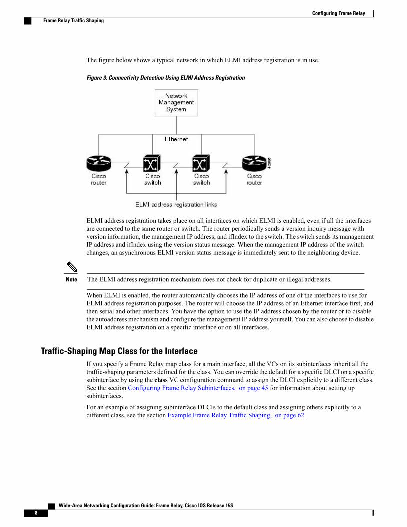
The figure below shows a typical network in which ELMI address registration is in use.
Figure 3: Connectivity Detection Using ELMI Address Registration
ELMI address registration takes place on all interfaces on which ELMI is enabled, even if all the interfacesare connected to the same router or switch. The router periodically sends a version inquiry message withversion information, the management IP address, and ifIndex to the switch. The switch sends its managementIP address and ifIndex using the version status message. When the management IP address of the switchchanges, an asynchronous ELMI version status message is immediately sent to the neighboring device.
The ELMI address registration mechanism does not check for duplicate or illegal addresses.Note
When ELMI is enabled, the router automatically chooses the IP address of one of the interfaces to use forELMI address registration purposes. The router will choose the IP address of an Ethernet interface first, andthen serial and other interfaces. You have the option to use the IP address chosen by the router or to disablethe autoaddress mechanism and configure the management IP address yourself. You can also choose to disableELMI address registration on a specific interface or on all interfaces.
Traffic-Shaping Map Class for the InterfaceIf you specify a Frame Relay map class for a main interface, all the VCs on its subinterfaces inherit all thetraffic-shaping parameters defined for the class. You can override the default for a specific DLCI on a specificsubinterface by using the class VC configuration command to assign the DLCI explicitly to a different class.See the section Configuring Frame Relay Subinterfaces, on page 45 for information about setting upsubinterfaces.
For an example of assigning subinterface DLCIs to the default class and assigning others explicitly to adifferent class, see the section Example Frame Relay Traffic Shaping, on page 62.
Wide-Area Networking Configuration Guide: Frame Relay, Cisco IOS Release 15S8
Configuring Frame RelayFrame Relay Traffic Shaping

Specifying Map Class with Queueing and Traffic-Shaping ParametersWhen defining a map class for Frame Relay, you can specify the average and peak rates (in bits per second)allowed on virtual circuits (VCs) associated with the map class. You can also specify either a custom queuelist or a priority queue group to use on VCs associated with the map class.
Defining Access ListsYou can specify access lists and associate them with the custom queue list defined for any map class. The listnumber specified in the access list and the custom queue list tie them together. See the appropriate protocolchapters for information about defining access lists for the protocols you want to transmit on the Frame Relaynetwork.
Defining Priority Queue Lists for the Map ClassYou can define a priority list for a protocol and you can also define a default priority list. The number usedfor a specific priority list ties the list to the Frame Relay priority group defined for a specified map class. Forexample, if you enter the frame relay priority-group 2 command for the map class "fast_vcs" and then youenter the priority-list 2 protocol decnet high command, that priority list is used for the "fast_vcs" map class.The average and peak traffic rates defined for the "fast_vcs" map class are used for DECnet traffic.
Defining Custom Queue Lists for the Map ClassYou can define a queue list for a protocol and a default queue list. You can also specify the maximum numberof bytes to be transmitted in any cycle. The number used for a specific queue list ties the list to the FrameRelay custom queue list defined for a specified map class.
For example, if you enter the frame relay custom-queue-list 1 command for the map class "slow_vcs" andthen you enter the queue-list 1 protocol ip list 100 command, that queue list is used for the "slow_vcs" mapclass; access-list 100 definition is also used for that map class and queue. The average and peak traffic ratesdefined for the "slow_vcs" map class are used for IP traffic that meets the access list 100 criteria.
Frame Relay SwitchingFrame Relay switching is a means of switching packets based on the DLCI, which can be considered theFrame Relay equivalent of aMAC address. You perform switching by configuring your Cisco router or accessserver into a Frame Relay network. There are two parts to a Frame Relay network:
• Frame Relay DTE (the router or access server)
• Frame Relay DCE switch
Wide-Area Networking Configuration Guide: Frame Relay, Cisco IOS Release 15S 9
Configuring Frame RelayFrame Relay Switching

The figure below illustrates Frame Relay switched networks. Routers A, B, and C are Frame Relay DTEsconnected to each other via a Frame Relay network.
Figure 4: Frame Relay Switched Network
Frame Relay switching is supported on the following interface types:
• Serial interfaces
• ISDN interfaces
Frame Relay switching is not supported on subinterfaces.Note
Frame Relay Switching over ISDN B ChannelsFrame Relay switching over ISDN B channels enables you to transport Frame Relay data over ISDN. Thisfeature allows small offices to be hubbed out of larger offices rather than being connected directly to the corenetwork. The hub router acts as a Frame Relay switch, switching between ISDN and serial interfaces, as shownin the figure below.
Figure 5: Router Used As a Frame Relay Switch over ISDN
Frame Relay switching over ISDN provides the following functionality:
• LMI is supported on ISDN Frame Relay DCE interfaces.
Wide-Area Networking Configuration Guide: Frame Relay, Cisco IOS Release 15S10
Configuring Frame RelayFrame Relay Switching

• A single BRI/PRI interface can use a combination of switched PVCs and terminated Frame Relay PVCs.
• Frame Relay switching supports both leased-line ISDN, on which a B channel is permanently connected,and switched ISDN, on which B channels may be dynamically set up and torn down.
Note the following restrictions for Frame Relay switching over ISDN:
• Frame Relay traffic shaping is not supported on ISDN interfaces.
• The router configured for Frame Relay switching over ISDN cannot initiate the ISDN call.
• PVC-level congestionmanagement is not supported over ISDN. Interface-level congestionmanagementis supported.
When Frame Relay switching is performed by using a dialer profile, encapsulation of the underlying physical(BRI) interface must be configured as high-level data link control (HDLC).
Frame Relay Traffic Shaping on Switched PVCsApplying Frame Relay traffic shaping to switched PVCs enables a router to be used as a Frame Relay portconcentrator in front of a Frame Relay switch. The Frame Relay switch will shape the concentrated trafficbefore sending it into the network. The figure below shows the network configuration.
Figure 6: Router Used As a Frame Relay Port Concentrator
When you configure traffic shaping, you will define the traffic-shaping parameters in a Frame Relay mapclass and then attach the map class to the interface or a single switched PVC. All the traffic-shaping map-classparameters are applicable to switched PVCs: namely, Bc, Be, CIR, minimum CIR, average rate, peak rate,and adaptive shaping.
Frame Relay traffic shaping must be enabled on the interface before traffic-shaping map-class parameterswill be effective. Note that when you enable Frame Relay traffic shaping, all PVCs, switched and terminated,will be shaped on that interface. Switched PVCs that are not associated with a map class will inherit shapingparameters from the interface or use default values.
Traffic PolicingTraffic policing prevents congestion on incoming PVCs by discarding or setting the DE bit on packets thatexceed specified traffic parameters.
Wide-Area Networking Configuration Guide: Frame Relay, Cisco IOS Release 15S 11
Configuring Frame RelayFrame Relay Switching

You can associate the map class with the interface or individual switched PVCs. Switched PVCs that are notassociated with a map class will inherit policing parameters from the interface.
If you use a map class to configure both traffic policing and shaping, use the in keyword to specify incomingtraffic for policing and the out keyword to specify outgoing traffic for shaping. If you configure shaping onone segment of a switched PVC and policing on the other, the shaping parameters will be derived from thepolicing parameters unless you specifically define shaping parameters in the map class.
Congestion Management on Switched PVCsFrame Relay congestion management can be used to manage outgoing traffic congestion on switched PVCs.When Frame Relay congestion management is enabled, one way that the router manages congestion is bysetting backward explicit congestion notification (BECN) and forward explicit congestion notification (FECN)bits on packets. When a switched PVC or interface is congested, packets experiencing congestion are markedwith the FECN bit, and packets traveling in the reverse direction are marked with the BECN bit. When thesebits reach a user device at the end of the network, the user device can react to the ECN bits and adjust theflow of traffic.
When the output interface queue reaches or exceeds the ECN excess threshold, Frame Relay bit packets onall PVCs crossing that interface will be marked with FECN or BECN, depending on their direction of travel.When the queue reaches or exceeds the ECN committed threshold, all Frame Relay packets will be markedwith FECN or BECN.
A second way the router manages congestion is by discarding Frame Relay packets that are marked with thediscard eligible (DE) bit and that exceed a specified level of congestion.
When the queue reaches or exceeds the DE threshold, Frame Relay packets with the DE bit will be discardedrather than queued.
You can define two levels of congestion. The first level applies to individual PVCs transmitting traffic inexcess of the committed information rate (CIR). The second level applies to all PVCs at an interface. Thisscheme allows you to adjust the congestion on PVCs transmitting above the CIR before applying congestionmanagement measures to all PVCs.
Congestion management parameters can be configured on the output interface queue and on traffic-shapingqueues.
FRF.12 Fragmentation on Switched PVCsThe FRF.12 Implementation Agreement allows long data frames to be fragmented into smaller pieces. Thisprocess allows real-time traffic and non-real-time traffic to be carried together on lower-speed links withoutcausing excessive delay to the real-time traffic. For further information about FRF.12 fragmentation, see thesection End-to-End FRF.12 Fragmentation, on page 20 later in this module.
Some Frame Relay access devices do not support the FRF.12 standard for end-to-end fragmentation. Largepackets sourced from these devices can cause significant serialization delay across low-speed trunks in switchednetworks. Using FRF.12 fragmentation can help prevent this delay. An edge router that receives large packetsfrom a Frame Relay access device will fragment those packets before transmitting them across the switchednetwork. The edge router that receives the fragmented packets will reassemble those packets before sendingthem to a Frame Relay access device that does not support FRF.12. If the receiving Frame Relay access devicedoes support FRF.12, the router will transmit the fragmented packets without reassembling them.
Note the following conditions and restrictions on FRF.12 fragmentation on switched PVCs:
• Frame Relay traffic shaping must be enabled.
Wide-Area Networking Configuration Guide: Frame Relay, Cisco IOS Release 15S12
Configuring Frame RelayFrame Relay Switching

• Interface queueing must be dual FIFO queueing or PVC interface priority queueing.
• Switched PVCs must be configured using the connect command.
• If the Frame Relay access device does not support FRF.12 fragmentation, the FRF.12 Support on SwitchedFrame Relay PVCs feature will not benefit the interface between the Frame Relay access device and theedge router. Fragmentation and reassembly occur on the interface between the edge router and theswitched Frame Relay network.
• If the Frame Relay access device is sending voice and unfragmented data on the same PVC, voice qualitywill suffer. The edge router will not reorder packets on switched PVCs.
Frame Relay End-to-End KeepalivesFrame Relay end-to-end keepalives enable monitoring of PVC status for network monitoring or backupapplications and are configurable on a per-PVC basis with configurable timers. The Frame Relay switch withinthe local PVC segment deduces the status of the remote PVC segment through a Network-to-Network Interface(NNI) and reports the status to the local router. If LMI support within the switch is not end-to-end, end-to-endkeepalives are the only source of information about the remote router. End-to-end keepalives verify that datais getting through to a remote device via end-to-end communication.
Each PVC connecting two end devices needs two separate keepalive systems, because the upstream path maynot be the same as the downstream path. One system sends out requests and handles responses to thoserequests--the send side--while the other system handles and replies to requests from the device at the otherend of the PVC--the receive side. The send side on one device communicates with the receive side on theother device, and vice versa.
The send side sends out a keepalive request and waits for a reply to its request. If a reply is received beforethe timer expires, a send-side Frame Relay end-to-end keepalive is recorded. If no reply is received beforethe timer expires, an error event is recorded. A number of the most recently recorded events are examined. Ifenough error events are accumulated, the keepalive status of the VC is changed from up to down, or if enoughconsecutive successful replies are received, the keepalive status of the VC is changed from down to up. Thenumber of events that will be examined is called the event window .
The receive side is similar to the send side. The receive side waits for requests and sends out replies to thoserequests. If a request is received before the timer expires, a success event is recorded. If a request is notreceived, an error event is recorded. If enough error events occur in the event window, the PVC state will bechanged from up to down. If enough consecutive success events occur, the state will be changed from downto up.
End-to-end keepalives can be configured in one of four modes: bidirectional, request, reply, or passive-reply.
• In bidirectional mode, both the send side and the receive side are enabled. The send side of the devicesends out and waits for replies to keepalive requests from the receive side of the other PVC device. Thereceive side of the device waits for and replies to keepalive requests from the send side of the other PVCdevice.
• In request mode, only the send side is enabled, and the device sends out and waits for replies to itskeepalive requests.
• In reply mode, only the receive side is enabled, and the device waits for and replies to keepalive requests.
• In passive-reply mode, the device only responds to keepalive requests, but does not set any timers orkeep track of any events.
Wide-Area Networking Configuration Guide: Frame Relay, Cisco IOS Release 15S 13
Configuring Frame RelayFrame Relay End-to-End Keepalives

Because end-to-end keepalives allow traffic flow in both directions, they can be used to carry control andconfiguration information from end to end. Consistency of information between end hosts is critical inapplications such as those relating to prioritized traffic and Voice over Frame Relay. Whereas SVCs canconvey such information within end-to-end signalling messages, PVCs will benefit from a bidirectionalcommunication mechanism.
End-to-end keepalives are derived from the Frame Relay LMI protocol and work between peer Ciscocommunications devices. The key difference is that rather than running over the signalling channel, as is thecase with LMI, end-to-end keepalives run over individual data channels.
Encapsulation of keepalive packets is proprietary; therefore, the feature is available only on Cisco devicesrunning a software release that supports the Frame Relay End-to-End Keepalive feature.
You must configure both ends of a VC to send keepalives. If one end is configured as bidirectional, the otherend must also be configured as bidirectional. If one end is configured as request, the other end must beconfigured as reply or passive-reply. If one end is configured as reply or passive-reply, the other end must beconfigured as request
PPP over Frame RelayPoint-to-point protocol (PPP) over Frame Relay allows a router to establish end-to-end PPP sessions overFrame Relay. This is done over a PVC, which is the only circuit currently supported. The PPP session doesnot occur unless the associated Frame Relay PVC is in an "active" state. The Frame Relay PVC can coexistwith other circuits using different Frame Relay encapsulation methods, such as RFC 1490 and the Ciscoproprietary method, over the same Frame Relay link. There can be multiple PPP over Frame Relay circuitson one Frame Relay link.
One PPP connection resides on one virtual access interface. This is internally created from a virtual templateinterface, which contains all necessary PPP and network protocol information and is shared by multiple virtualaccess interfaces. The virtual access interface is coexistent with the creation of the Frame Relay circuit whenthe correspondingDLCI is configured. Hardware compression and fancy queueing algorithms, such as weightedfair queueing, custom queueing, and priority queueing, are not applied to virtual access interfaces.
PPP over Frame Relay is only supported on IP. IP datagrams are transported over the PPP link using RFC1973 compliant Frame Relay framing. The frame format is shown in the figure below.
Figure 7: PPP over Frame Relay Frame Format
The table below lists the Frame Relay frame format components illustrated in the figure above.
Wide-Area Networking Configuration Guide: Frame Relay, Cisco IOS Release 15S14
Configuring Frame RelayPPP over Frame Relay

Table 1: PPP Frame Relay Frame Format Descriptions
DescriptionField
A single byte that indicates the beginning or end ofa frame.
Flag
A two-byte field that indicates the logical connectionthat maps to the physical channel; the DLCI.
Address
A single byte that calls for transmission of user data.PPP over Frame Relay uses a value of 0X03, whichindicates that the frame is an unnumbered information(UI) frame.
Control
Network layer protocol ID--a single byte that uniquelyidentifies a PPP packet to Frame Relay.
NLPID
PPP packet type.PPP protocol
The figure below shows remote users running PPP to access their Frame Relay corporate networks.
Figure 8: PPP over Frame Relay Scenario
Before PPP over FrameRelay is configured, FrameRelaymust be enabled on the router using the encapsulationframe-relaycommand. The only task required in order to implement PPP over Frame Relay is to configurethe interface with the locally terminated PVC and the associated virtual template for PPP and IP, as describedin the following section.
Wide-Area Networking Configuration Guide: Frame Relay, Cisco IOS Release 15S 15
Configuring Frame RelayPPP over Frame Relay

After configuring Frame Relay encapsulation on the Cisco router or access server, you must configure thephysical interface with the PVC and apply a virtual template with PPP encapsulation to the DLCI.
Understanding Frame Relay SubinterfacesFrame Relay subinterfaces provide a mechanism for supporting partially meshed Frame Relay networks. Mostprotocols assume transitivity on a logical network; that is, if station A can talk to station B, and station B cantalk to station C, then station A should be able to talk to station C directly. Transitivity is true on LANs, butnot on Frame Relay networks unless A is directly connected to C.
Additionally, certain protocols such as AppleTalk and transparent bridging cannot be supported on partiallymeshed networks because they require split horizon . Split horizon is a routing technique in which a packetreceived on an interface cannot be sent from the same interface even if received and transmitted on differentVCs.
Configuring Frame Relay subinterfaces ensures that a single physical interface is treated as multiple virtualinterfaces. This treatment allows you to overcome split horizon rules. Packets received on one virtual interfacecan be forwarded to another virtual interface even if they are configured on the same physical interface.
Subinterfaces address the limitations of Frame Relay networks by providing a way to subdivide a partiallymeshed Frame Relay network into a number of smaller, fully meshed (or point-to-point) subnetworks. Eachsubnetwork is assigned its own network number and appears to the protocols as if it were reachable througha separate interface. (Note that point-to-point subinterfaces can be unnumbered for use with IP, reducing theaddressing burden that might otherwise result.)
The figure below shows a five-node Frame Relay network that is partially meshed (network A). If the entirenetwork is viewed as a single subnetwork (with a single network number assigned), most protocols assumethat node A can transmit a packet directly to node E, when in fact it must be relayed through nodes C and D.This network can be made to work with certain protocols (for example, IP), but will not work at all with otherprotocols (for example, AppleTalk) because nodes C and D will not relay the packet out the same interface
Wide-Area Networking Configuration Guide: Frame Relay, Cisco IOS Release 15S16
Configuring Frame RelayUnderstanding Frame Relay Subinterfaces

on which it was received. One way to make this network work fully is to create a fully meshed network(network B), but doing so requires a large number of PVCs, which may not be economically feasible.
Figure 9: Using Subinterfaces to Provide Full Connectivity on a Partially Meshed Frame Relay Network
Using subinterfaces, you can subdivide the Frame Relay network into three smaller subnetworks (networkC) with separate network numbers. Nodes A, B, and C are connected to a fully meshed network, and nodesC and D, as well as nodes D and E, are connected via point-to-point networks. In this configuration, nodes Cand D can access two subinterfaces and can therefore forward packets without violating split horizon rules.If transparent bridging is being used, each subinterface is viewed as a separate bridge port.
Wide-Area Networking Configuration Guide: Frame Relay, Cisco IOS Release 15S 17
Configuring Frame RelayUnderstanding Frame Relay Subinterfaces
Subinterface Addressing
Point-to-Point Subinterfaces
For point-to-point subinterfaces, the destination is presumed to be known and is identified or implied in theframe-relay interface-dlci command. This command is used to enable routing protocols on main interfacesthat are configured to use Inverse ARP. This command is also helpful for assigning a specific class to a singlePVC on a multipoint subinterface.
If you define a subinterface for point-to-point communication, you cannot reassign the same subinterfacenumber to be used for multipoint communication without first rebooting the router or access server. Instead,you can simply avoid using that subinterface number and use a different subinterface number.
Addressing on Multipoint Subinterfaces
• Accepting Inverse ARP for Dynamic Address Mapping on Multipoint Subinterfaces, on page 46
• Configuring a Map Group with E.164 or X.121 Addresses, on page 32
Accepting Inverse ARP for Dynamic Address Mapping on Multipoint Subinterfaces
Dynamic address mapping uses Frame Relay Inverse ARP to request the next-hop protocol address for aspecific connection, given a DLCI. Responses to Inverse ARP requests are entered in an address-to-DLCImapping table on the router or access server; the table is then used to supply the next-hop protocol addressor the DLCI for outgoing traffic.
Since the physical interface is now configured as multiple subinterfaces, you must provide information thatdistinguishes a subinterface from the physical interface and associates a specific subinterface with a specificDLCI.
Inverse ARP is enabled by default for all protocols it supports, but can be disabled for specific protocol-DLCIpairs. As a result, you can use dynamic mapping for some protocols and static mapping for other protocolson the same DLCI. You can explicitly disable Inverse ARP for a protocol-DLCI pair if you know the protocolis not supported on the other end of the connection. See the section "Disabling or Reenabling Frame RelayInverse ARP, on page 49" later in this chapter for more information.
Because Inverse ARP is enabled by default for all protocols that it supports, no additional command is requiredto configure dynamic address mapping on a subinterface.
Configuring Static Address Mapping on Multipoint Subinterfaces
A static map links a specified next-hop protocol address to a specified DLCI. Static mapping removes theneed for Inverse ARP requests; when you supply a static map, Inverse ARP is automatically disabled for thespecified protocol on the specified DLCI.
You must use static mapping if the router at the other end either does not support Inverse ARP at all or doesnot support Inverse ARP for a specific protocol that you want to use over Frame Relay.
Backup Interface for a Subinterface
Both point-to-point and multipoint Frame Relay subinterfaces can be configured with a backup interface. Thisapproach allows individual permanent virtual circuit (PVCs) to be backed up in case of failure rather than
Wide-Area Networking Configuration Guide: Frame Relay, Cisco IOS Release 15S18
Configuring Frame RelayUnderstanding Frame Relay Subinterfaces

depending on the entire Frame Relay connection to fail before the backup takes over. You can configure asubinterface for backup on failure only, not for backup based on loading of the line.
If the main interface has a backup interface, it has a precedence over the backup interface of the subinterfacein the case of complete loss of connectivity with the Frame Relay network. As a result, a subinterface backupis activated only in the following cases:
• If the main interface is up
• If the interface is down and does not have a backup interface defined
If a subinterface fails while its backup interface is in use, and the main interface goes down, the backupsubinterface remains connected.
Disabling or Reenabling Frame Relay Inverse ARPFrame Relay Inverse ARP is a method of building dynamic address mappings in Frame Relay networksrunning AppleTalk, Banyan VINES, DECnet, IP, Novell IPX, and XNS. Inverse ARP allows the router oraccess server to discover the protocol address of a device associated with the VC.
Inverse ARP creates dynamic address mappings, as contrasted with the frame-relay map command, whichdefines static mappings between a specific protocol address and a specific DLCI.
Inverse ARP is enabled by default but can be disabled explicitly for a given protocol and DLCI pair. Disableor reenable Inverse ARP under the following conditions:
• Disable Inverse ARP for a selected protocol and DLCI pair when you know that the protocol is notsupported at the other end of the connection.
• Reenable Inverse ARP for a protocol and DLCI pair if conditions or equipment change and the protocolis then supported at the other end of the connection.
If you change from a point-to-point subinterface to a multipoint subinterface, change the subinterfacenumber. Frame Relay Inverse ARP will be on by default, and no further action is required.
Note
You do not need to enable or disable Inverse ARP if you have a point-to-point interface, because there is onlya single destination and discovery is not required.
Broadcast Queue for an InterfaceVery large Frame Relay networks may have performance problems when many DLCIs terminate in a singlerouter or access server that must replicate routing updates and service advertising updates on each DLCI. Theupdates can consume access-link bandwidth and cause significant latency variations in user traffic; the updatescan also consume interface buffers and lead to higher packet rate loss for both user data and routing updates.
To avoid such problems, you can create a special broadcast queue for an interface. The broadcast queue ismanaged independently of the normal interface queue, has its own buffers, and has a configurable size andservice rate.
A broadcast queue is given a maximum transmission rate (throughput) limit measured in both bytes per secondand packets per second. The queue is serviced to ensure that no more than this maximum is provided. Thebroadcast queue has priority when transmitting at a rate below the configured maximum, and hence has a
Wide-Area Networking Configuration Guide: Frame Relay, Cisco IOS Release 15S 19
Configuring Frame RelayDisabling or Reenabling Frame Relay Inverse ARP
guaranteed minimum bandwidth allocation. The two transmission rate limits are intended to avoid floodingthe interface with broadcasts. The actual transmission rate limit in any second is the first of the two rate limitsthat is reached.
Frame Relay FragmentationCisco has developed three types of Frame Relay fragmentation, which are described in the following sections:
The following provides further information about Frame Relay fragmentation:
End-to-End FRF.12 FragmentationThe purpose of end-to-end FRF.12 fragmentation is to support real-time and non-real-time data packets onlower-speed links without causing excessive delay to the real-time data. FRF.12 fragmentation is defined bythe FRF.12 ImplementationAgreement. This standardwas developed to allow long data frames to be fragmentedinto smaller pieces (fragments) and interleaved with real-time frames. In this way, real-time and non-real-timedata frames can be carried together on lower-speed links without causing excessive delay to the real-timetraffic.
End-to-end FRF.12 fragmentation is recommended for use on permanent virtual circuits (PVCs) that sharelinks with other PVCs that are transporting voice and on PVCs transporting Voice over IP (VoIP). AlthoughVoIP packets should not be fragmented, they can be interleaved with fragmented packets.
FRF.12 is configured on a per-PVC basis using a Frame Relay map class. The map class can be applied toone or many PVCs. Frame Relay traffic shaping must be enabled on the interface in order for fragmentationto work.
When Frame Relay fragmentation is configured, WFQ or LLQ is mandatory. If a map class is configuredfor Frame Relay fragmentation and the queueing type on that map class is notWFQ or LLQ, the configuredqueueing type is automatically overridden by WFQ with the default values. To configure LLQ for FrameRelay, refer to the Cisco IOS Quality of Service Solutions Configuration Guide , Release 12.2.
Note
Setting the Fragment SizeSet the fragment size so that voice packets are not fragmented and do not experience a serialization delaygreater than 20 ms.
To set the fragment size, the link speed must be taken into account. The fragment size should be larger thanthe voice packets, but small enough to minimize latency on the voice packets. Turn on fragmentation for lowspeed links (less than 768 kbps).
Set the fragment size based on the lowest port speed between the routers. For example, if there is a hub andspoke Frame Relay topology where the hub has a T1 speed and the remote routers have 64 kbps port speeds,the fragment size needs to be set for the 64 kbps speed on both routers. Any other PVCs that share the samephysical interface need to configure the fragmentation to the size used by the voice PVC.
If the lowest link speed in the path is 64 kbps, the recommended fragment size (for 10 ms serialization delay)is 80 bytes. If the lowest link speed is 128 kbps, the recommended fragment size is 160 bytes.
For more information, refer to the " Fragmentation (FRF.12)" section in the VoIP over Frame Relay withQuality of Service (Fragmentation, Traffic Shaping, LLQ / IP RTP Priority) document.
Wide-Area Networking Configuration Guide: Frame Relay, Cisco IOS Release 15S20
Configuring Frame RelayFrame Relay Fragmentation

Frame Relay Fragmentation Using FRF.11 Annex CWhen VoFR (FRF.11) and fragmentation are both configured on a PVC, the Frame Relay fragments are sentin the FRF.11 Annex C format. This fragmentation is used when FRF.11 voice traffic is sent on the PVC, andit uses the FRF.11 Annex C format for data.
With FRF.11, all data packets contain fragmentation headers, regardless of size. This form of fragmentationis not recommended for use with Voice over IP (VoIP).
See the chapter "Configuring Voice over Frame Relay" in the Cisco IOS Voice, Video, and Fax ConfigurationGuide for configuration tasks and examples for Frame Relay fragmentation using FRF.11 Annex C.
Cisco-Proprietary FragmentationCisco-proprietary fragmentation is used on data packets on a PVC that is also used for voice traffic. Whenthe vofr cisco command is configured on a DLCI and fragmentation is enabled on a map class, the Cisco 2600series, 3600 series, and 7200 series routers can interoperate as tandem nodes (but cannot perform calltermination) with Cisco MC3810 concentrators running Cisco IOS releases prior to 12.0(3)XG or 12.0(4)T.
To configure Cisco-proprietary voice encapsulation, use the vofr cisco command. You must then configurea map class to enable voice traffic on the PVCs.
See the chapter "Configuring Voice over Frame Relay" in the Cisco IOS Voice, Video, and Fax ConfigurationGuide for configuration tasks and examples for Cisco-proprietary fragmentation.
Frame Relay Fragmentation and Hardware Compression InteroperabilityFRF.12, FRF.11 Annex C, and Cisco-proprietary fragmentation can be used with FRF.9 or data-streamhardware compression on interfaces and virtual circuits (VCs) using Cisco-proprietary or Internet EngineeringTask Force (IETF) encapsulation types.
When payload compression and Frame Relay fragmentation are used at the same time, payload compressionis always performed before fragmentation.
Frame Relay fragmentation can be used with the following hardware compression modules:
• Cisco 2600 AIM-COMPR2
• Cisco 3620 and 3640 NM-COMPR
• Cisco 3660 AIM-COMPR4
• Cisco 7200 SA-COMPR
Voice over Frame Relay and Voice over IP packets will not be payload-compressed when Frame Relayfragmentation is configured.
On VCs using IETF encapsulation, FRF.9 hardware and software compression will work with FrameRelay fragmentation but will not work with header compression.
Note
Wide-Area Networking Configuration Guide: Frame Relay, Cisco IOS Release 15S 21
Configuring Frame RelayFrame Relay Fragmentation

Frame Relay Fragmentation Conditions and RestrictionsWhen Frame Relay fragmentation is configured, the following conditions and restrictions apply:
• WFQ and LLQ at the PVC level are the only queueing strategies that can be used.
• Frame Relay traffic shaping (FRTS) must be configured to enable Frame Relay fragmentation (excepton the Cisco 7500 series routers on which Versatile Interface Processor-Based Distributed FRF.11 andFRF.12 is enabled).
• VoFR frames are never fragmented, regardless of size.
• When end-to-end FRF.12 fragmentation is used, the VoIP packets will not include the FRF.12 header,provided the size of the VoIP packet is smaller than the fragment size configured. However, when FRF.11Annex C or Cisco-proprietary fragmentations are used, VoIP packets will include the fragmentationheader.
• If fragments arrive out of sequence, packets are dropped.
Fragmentation is performed after frames are removed from the WFQ.Note
Payload Compression
Packet-by-Packet Payload CompressionYou can configure payload compression on point-to-point or multipoint interfaces or subinterfaces. Payloadcompression uses the Predictor method to predict what the next character in the frame will be. Because theprediction is done packet by packet, the dictionary is not conserved across packet boundaries. Payloadcompression on each VC consumes approximately 40 kilobytes for dictionary memory.
Standard-Based FRF.9 CompressionFrame Relay compression can now occur on the VIP board, on the Compression Service Adapter (CSA), oron the main CPU of the router. FRF.9 is standard-based and therefore provides multivendor compatibility.FRF.9 compression uses relatively higher compression ratios, allowing more data to be compressed for fastertransmission. FRF.9 compression provides the ability to maintain multiple decompression/compressionhistories on a per-DLCI basis.
The CSA hardware has been in use on the Cisco 7200 series and Cisco 7500 series platforms, but it has hadno support for Frame Relay compression. The CSA can be used in the Cisco 7200 series or in thesecond-generation Versatile Interface Processor (VIP2) in all Cisco 7500 series routers. The specific VIP2model required for the CSA is VIP2-40, which has 2 MB of SRAM and 32 MB of DRAM.
Selecting FRF.9 Compression Method
The router enables compression in the following order:
Wide-Area Networking Configuration Guide: Frame Relay, Cisco IOS Release 15S22
Configuring Frame RelayPayload Compression

1 If the router contains a compression service adapter, compression is performed in the CSA hardware(hardware compression).
2 If the CSA is not available, compression is performed in the software installed on the VIP2 card (distributedcompression).
3 If the VIP2 card is not available, compression is performed in the main processor of the router (softwarecompression).
Cisco-proprietary Data-Stream CompressionData-stream compression is a proprietary hardware and software compression protocol that can be used onthe same VC or interface and IP header compression. Data-stream compression is functionally equivalent toFRF.9 compression and must be used with Cisco-proprietary encapsulation. Frame Relay fragmentation canalso be used with data-stream compression.
TCP IP Header CompressionTCP/IP header compression, as described by RFC 1144, Compressing TCP/IP Headers for Low-Speed SerialLinks is designed to improve the efficiency of bandwidth utilization over low-speed serial links. A typicalTCP/IP packet includes a 40-byte datagram header. Once a connection is established, the header informationis redundant and need not be repeated in every packet that is sent. Reconstructing a smaller header that identifiesthe connection, indicates the fields that have changed and the amount of change reduces the number of bytestransmitted. The average compressed header is 10 bytes long.
For this algorithm to function, packets must arrive in order. If packets arrive out of order, the reconstructionwill appear to create regular TCP/IP packets but the packets will not match the original. Because priorityqueueing changes the order in which packets are transmitted, enabling priority queueing on the interface isnot recommended.
If you configure an interface with Cisco-proprietary encapsulation and TCP/IP header compression, FrameRelay IP maps inherit the compression characteristics of the interface. However, if you configure theinterface with IETF encapsulation, the interface cannot be configured for compression. Frame Relay mapswill have to be configured individually to support TCP/IP header compression.
Note
Specifying an Individual IP Map for TCP IP Header Compression
An interface configured to support TCP/IP header compression does not also support priority queuing orcustom queuing.
Note
TCP/IP header compression requires Cisco-proprietary encapsulation. If you need to have IETF encapsulationon an interface as a whole, you can still configure a specific IP map to use Cisco-proprietary encapsulationand TCP header compression. In addition, if you configure the interface to perform TCP/IP header compression,you can still configure a specific IP map not to compress TCP/IP headers.
Wide-Area Networking Configuration Guide: Frame Relay, Cisco IOS Release 15S 23
Configuring Frame RelayTCP IP Header Compression

You can specify whether TCP/IP header compression is active or passive. Active compression subjects everyoutgoing packet to TCP/IP header compression. Passive compression subjects an outgoing TCP/IP packet toheader compression only if a packet had a compressed TCP/IP header when it was received.
Specifying an Interface for TCP IP Header CompressionYou can configure the interface with active or passive TCP/IP header compression. Active compression, thedefault, subjects all outgoing TCP/IP packets to header compression. Passive compression subjects an outgoingpacket to header compression only if the packet had a compressed TCP/IP header when it was received onthat interface.
If an interface configured with Cisco-proprietary encapsulation is later configured with IETF encapsulation,all TCP/IP header compression characteristics are lost. To apply TCP/IP header compression over aninterface configured with IETF encapsulation, you must configure individual IP maps.
Note
If you configure an interface with Cisco-proprietary encapsulation and TCP/IP header compression, FrameRelay IP maps inherit the compression characteristics of the interface. However, if you configure the interfacewith IETF encapsulation, the interface cannot be configured for compression. Frame Relay maps will haveto be configured individually to support TCP/IP header compression.
Real-Time Header Compression with Frame Relay EncapsulationReal-time Transport Protocol (RTP) is a protocol used for carrying packetized audio and video traffic overan IP network, providing end-to-end network transport functions intended for these real-time traffic applicationsand multicast or unicast network services. RTP is described in RFC 1889. RTP is not intended for data traffic,which uses TCP or UDP.
Discard EligibilityFrame Relay packets can be set with low priority or low time sensitivity. These packets will be the first to bedropped when a Frame Relay switch is congested. The mechanism that allows a Frame Relay switch to identifysuch packets is the discard eligibility (DE) bit.
Discard eligibility requires the Frame Relay network to be able to interpret the DE bit. Some networks takeno action when the DE bit is set, and others use the DE bit to determine which packets to discard. The bestinterpretation is to use the DE bit to determine which packets should be dropped first and also which packetshave lower time sensitivity.
You can create DE lists that identify the characteristics of packets to be eligible for discarding, and you canalso specify DE groups to identify the data link connection identifier (DLCI) that is affected.
You can create DE lists based on the protocol or the interface, and on characteristics such as fragmentationof the packet, a specific TCP or UDP port, an access list number, or a packet size.
Wide-Area Networking Configuration Guide: Frame Relay, Cisco IOS Release 15S24
Configuring Frame RelayReal-Time Header Compression with Frame Relay Encapsulation
DLCI Priority LevelsData Link Connection Identifier (DLCI) priority levels allow you to separate different types of traffic andprovides a traffic management tool for congestion problems caused by the following:
• Mixing batch and interactive traffic over the same DLCI
• Queuing traffic from sites with high-speed access to destination sites with lower-speed access
Before you configure the DLCI priority levels, you must:
• Enable Frame Relay encapsulation.
• Define dynamic or static address mapping.
• Ensure that you define each of the DLCIs to which you intend to apply levels. You can associatepriority-level DLCIs with subinterfaces.
• Configure the LMI.
DLCI priority levels provide a way to define multiple parallel DLCIs for different types of traffic. DLCIpriority levels do not assign priority queues within the device or access server. In fact, they are independentof the priority queues of the device. However, if you enable queuing and use the same DLCIs for queuing,then high-priority DLCIs can be put into high-priority queues.
Note
How to Configure Frame Relay
Enabling Frame Relay Encapsulation on an Interface
Frame Relay encapsulation is a prerequisite for any Frame Relay commands on an interface.Note
To enable Frame Relay encapsulation on the interface level, use the following commands beginning in globalconfiguration mode:
SUMMARY STEPS
1. enable2. configure terminal3. interface typenumber4. encapsulation frame-relay[ietf]5. end
Wide-Area Networking Configuration Guide: Frame Relay, Cisco IOS Release 15S 25
Configuring Frame RelayDLCI Priority Levels

DETAILED STEPS
PurposeCommand or Action
Enables privileged EXEC mode.enableStep 1
Example:
Device> enable
• Enter your password if prompted.
Enters global configuration mode.configure terminal
Example:
Device# configure terminal
Step 2
Specifies the interface, and enters interface configurationmode.
interface typenumber
Example:
Device(config)# int ethernet 0/1
Step 3
Enables and specifies the Frame Relay encapsulationmethod.
encapsulation frame-relay[ietf]
Example:
Device(config-if)# encapsulation frame-relayietf
Step 4
Returns to privileged EXEC mode.end
Example:
Device(config-if)# end
Step 5
Wide-Area Networking Configuration Guide: Frame Relay, Cisco IOS Release 15S26
Configuring Frame RelayEnabling Frame Relay Encapsulation on an Interface

Configuring Static Address MappingTo establish static mapping according to your network needs, use one of the following commands in interfaceconfiguration mode:
PurposeCommand
Maps between a next-hop protocol address and DLCIdestination address. The supported protocols and thecorresponding keywords to enable them are asfollows:
• IP--ip
• DECnet--decnet
• AppleTalk--appletalk
• XNS--xns
• Novell IPX--ipx
• VINES--vines
• ISO CLNS--clns
Router(config-if)# frame-relay map protocolprotocol-address dlci [broadcast] [ietf] [cisco]
Defines a DLCI used to send ISO CLNS frames.Router(config-if)# frame-relay map clns dlci[broadcast]
Defines a DLCI destination bridge.Router(config-if)# frame-relay map bridgedlci [broadcast] [ietf]
Explicitly Configuring the LMI
Setting the LMI TypeIf the device or access server is attached to a public data network (PDN), the LMI type must match the typeused on the public network. Otherwise, the LMI type can be set to suit the requirements of your private FrameRelay network. You can set one of the following three types of LMIs on Cisco devices:
• ANSI T1.617 Annex D
• Cisco
• ITU-T Q.933 Annex A
To do so, use the following commands beginning in interface configuration mode:
Wide-Area Networking Configuration Guide: Frame Relay, Cisco IOS Release 15S 27
Configuring Frame RelayConfiguring Static Address Mapping

SUMMARY STEPS
1. enable2. configure terminal3. interface typenumber4. frame-relay lmi-type {ansi | cisco | q933a}5. end6. copy nvram:startup-config destination
DETAILED STEPS
PurposeCommand or Action
Enables privileged EXEC mode.enableStep 1
Example:
Device> enable
• Enter your password if prompted.
Enters global configuration mode.configure terminal
Example:
Device# configure terminal
Step 2
Specifies the interface, and enters interfaceconfiguration mode.
interface typenumber
Example:
Device(config)# int ethernet 0/1
Step 3
Sets the LMI type.frame-relay lmi-type {ansi | cisco | q933a}
Example:
Device(config-if)#
Step 4
Returns to privileged EXEC mode.end
Example:
Device(config-if)# end
Step 5
Writes the LMI type to NVRAM.copy nvram:startup-config destination
Example:
Device#
Step 6
Wide-Area Networking Configuration Guide: Frame Relay, Cisco IOS Release 15S28
Configuring Frame RelayExplicitly Configuring the LMI

Setting the LMI Keepalive IntervalA keepalive interval must be set to configure the LMI. By default, this interval is 10 seconds and, accordingto the LMI protocol, must be less than the corresponding interval on the switch. To set the keepalive interval,use the following command in interface configuration mode:
PurposeCommand
Sets the LMI keepalive interval.Router(config-if)# keepalive number
Setting the LMI Polling and Timer IntervalsYou can set various optional counters, intervals, and thresholds to fine-tune the operation of your LocalManagement Interface data terminal equipment (LMI DTE) and data communications equipment (DCE)devices. Set these attributes by using one or more of the following commands in interface configurationmode:
PurposeCommand
Sets the DCE and Network-to-Network Interface(NNI) error threshold.
frame-relay lmi-n392dce threshold
Sets the DCE and NNI monitored events count.frame-relay lmi-n393dce events
Sets the polling verification timer on a DCE or NNIinterface.
frame-relay lmi-t392dce seconds
Sets a full status polling interval on a DTE or NNIinterface.
frame-relay lmi-n391dte keep-exchanges
Sets the DTE or NNI error threshold.frame-relay lmi-n392dte threshold
Sets the DTE and NNI monitored events count.frame-relay lmi-n393dte events
Enabling Frame Relay SVC Service
Configuring SVCs on a Physical InterfaceTo enable SVC operation on a Frame Relay interface, use the following commands beginning in globalconfiguration mode:
Wide-Area Networking Configuration Guide: Frame Relay, Cisco IOS Release 15S 29
Configuring Frame RelayEnabling Frame Relay SVC Service

SUMMARY STEPS
1. Router(config)# interface type number2. Router(config-if)# ip address ip-address mask3. Router(config-if)# encapsulation frame-relay4. Router(config-if)#map-group group-name5. Router(config-if)# frame-relay svc
DETAILED STEPS
PurposeCommand or Action
Specifies the physical interface.Router(config)# interface type numberStep 1
Specifies the interface IP address, if needed.Router(config-if)# ip address ip-address maskStep 2
Enables Frame Relay encapsulation on the interface.Router(config-if)# encapsulation frame-relayStep 3
Assigns a map group to the interface. Map group details arespecified with themap-list command.
Router(config-if)#map-group group-nameStep 4
Enables Frame Relay SVC support on the interface.Router(config-if)# frame-relay svcStep 5
Configuring SVCs on a Subinterface
This task offers additional flexibility for SVC configuration and operation.Note
To configure Frame Relay SVCs on a subinterface, complete all the commands in the preceding section,except assigning the map group. After the physical interface is configured, use the following commandsbeginning in global configuration mode:
SUMMARY STEPS
1. Router(config)# interface type number . subinterface-number {multipoint | point-to-point}2. Router(config-subif)# ip address ip-address mask3. Router(config-subif)#map-group group-name
DETAILED STEPS
PurposeCommand or Action
Specifies a subinterface configured for SVCoperation.
Router(config)# interface type number . subinterface-number{multipoint | point-to-point}
Step 1
Wide-Area Networking Configuration Guide: Frame Relay, Cisco IOS Release 15S30
Configuring Frame RelayEnabling Frame Relay SVC Service

PurposeCommand or Action
Specifies the subinterface IP address, if needed.Router(config-subif)# ip address ip-address maskStep 2
Assigns a map group to the subinterface.Router(config-subif)#map-group group-nameStep 3
Configuring a Map ClassPerform the following tasks to configure a map class:
• Specify the map class name. (Required)
• Specify a custom queue list for the map class. (Optional)
• Specify a priority queue list for the map class. (Optional)
• Enable BECN feedback to throttle the output rate on the SVC for the map class. (Optional)
• Set nondefault QoS values for the map class (no need to set the QoS values; default values are provided).(Optional)
You can define multiple map classes. A map class is associated with a static map, not with the interfaceor subinterface. Because of the flexibility this association allows, you can define different map classes fordifferent destinations.
Note
To configure a map class, use the following commands beginning in global configuration mode:
SUMMARY STEPS
1. Router(config)#map-class frame-relay map-class-name2. Router(config-map-class)# frame-relay custom-queue-list list-number3. Router(config-map-class)# frame-relay priority-group list-number4. Router(config-map-class)# frame-relay adaptive-shaping[becn | foresight]1
5. Router(config-map-class)# frame-relay cir in bps6. Router(config-map-class)# frame-relay cir out bps7. Router(config-map-class)# frame-relay mincir in bps2
8. Router(config-map-class)# frame-relay mincir out bpsConfiguring a Map Class, on page 319. Router(config-map-class)# frame-relay bc in bitsConfiguring a Map Class, on page 3110. Router(config-map-class)# frame-relay bc out bitsConfiguring a Map Class, on page 3111. Router(config-map-class)# frame-relay be in bitsConfiguring a Map Class, on page 3112. Router(config-map-class)# frame-relay be out bitsConfiguring a Map Class, on page 3113. Router(config-map-class)# frame-relay idle-timer secondsConfiguring a Map Class, on page 31
Wide-Area Networking Configuration Guide: Frame Relay, Cisco IOS Release 15S 31
Configuring Frame RelayEnabling Frame Relay SVC Service

DETAILED STEPS
PurposeCommand or Action
Specifies Frame Relay map class name and entersmap class configuration mode.
Router(config)#map-class frame-relay map-class-nameStep 1
Specifies a custom queue list to be used for the mapclass.
Router(config-map-class)# frame-relay custom-queue-listlist-number
Step 2
Assigns a priority queue to VCs associated with themap class.
Router(config-map-class)# frame-relay priority-grouplist-number
Step 3
Enables the type of BECN feedback to throttle theframe-transmission rate.
Router(config-map-class)# frame-relayadaptive-shaping[becn | foresight]1
Step 4
Specifies the inbound committed information rate(CIR), in bits per second.
Router(config-map-class)# frame-relay cir in bpsStep 5
Specifies the outbound CIR, in bits per second.Router(config-map-class)# frame-relay cir out bpsStep 6
Sets the minimum acceptable incoming CIR, in bitsper second.
Router(config-map-class)# frame-relay mincir in bps2Step 7
Sets the minimum acceptable outgoing CIR, in bitsper second.
Router(config-map-class)# frame-relay mincir outbpsConfiguring a Map Class, on page 31
Step 8
Sets the incoming committed burst size (Bc), in bits.Router(config-map-class)# frame-relay bc inbitsConfiguring a Map Class, on page 31
Step 9
Sets the outgoing Bc, in bits.Router(config-map-class)# frame-relay bc outbitsConfiguring a Map Class, on page 31
Step 10
Sets the incoming excess burst size (Be), in bits.Router(config-map-class)# frame-relay be inbitsConfiguring a Map Class, on page 31
Step 11
Sets the outgoing Be, in bits.Router(config-map-class)# frame-relay be outbitsConfiguring a Map Class, on page 31
Step 12
Sets the idle timeout interval, in seconds.Router(config-map-class)# frame-relay idle-timersecondsConfiguring a Map Class, on page 31
Step 13
1 This command replaces the frame-relay becn-response-enable command, which will be removed in a future Cisco IOS release. If you use the frame-relaybecn-response-enable command in scripts, you should replace it with the frame-relay adaptive-shaping becn command.
2 The in and out keywords are optional. Configuring the command without the in and out keywords will apply that value to both the incoming and the outgoingtraffic values for the SVC setup. For example, frame-relay cir 56000 applies 56000 to both incoming and outgoing traffic values for setting up the SVC.
Configuring a Map Group with E.164 or X.121 AddressesAfter you have defined a map group for an interface, you can associate the map group with a specific sourceand destination address to be used. You can specify E.164 addresses or X.121 addresses for the source and
Wide-Area Networking Configuration Guide: Frame Relay, Cisco IOS Release 15S32
Configuring Frame RelayEnabling Frame Relay SVC Service

destination. To specify the map group to be associated with a specific interface, use the following commandin global configuration mode:
PurposeCommand
Specifies the map group associated with specificsource and destination addresses for the SVC.Router(config)# map-list map-group-name
source-addr {e164 | x121} source-addressdest-addr {e164 | x121} destination-address
Associating the Map Class with Static Protocol Address MapsTo define the protocol addresses under amap-list command and associate each protocol address with aspecified map class, use the class command. Use this command for each protocol address to be associatedwith a map class. To associate a map class with a protocol address, use the following command in map listconfiguration mode:
PurposeCommand
Specifies a destination protocol address and a FrameRelay map class name from which to derive QoSinformation.
• The ietf keyword specifies RFC 1490encapsulation
• The broadcast keyword specifies thatbroadcasts must be carried.
• The trigger keyword, which can be configuredonly if broadcast is also configured, enables abroadcast packet to trigger an SVC. If an SVCalready exists that uses this map class, the SVCwill carry the broadcast.
Router(config-map-list)# protocolprotocol-address class class-name [ietf][broadcast [trigger]]
Configuring LAPF Parameters
The LAPF tasks are not required and not recommended unless you understand thoroughly the impacts onyour network.
Note
By default, the Frame Reject frame is sent at the LAPF Frame Reject procedure.
Frame Relay Link Access Procedure for Frame Relay (LAPF) commands are used to tune Layer 2 systemparameters to work well with the Frame Relay switch. Normally, you do not need to change the default settings.
Wide-Area Networking Configuration Guide: Frame Relay, Cisco IOS Release 15S 33
Configuring Frame RelayEnabling Frame Relay SVC Service

However, if the Frame Relay network indicates that it does not support the Frame Reject frame (FRMR) atthe LAPF Frame Reject procedure, use the following command in interface configuration mode:
PurposeCommand
Selects not to send FRMR frames at the LAPF FrameReject procedure.Router(config-if)# no frame-relay lapf frmr
Changing Layer 2 Parameters for Your Network
Manipulation of Layer 2 parameters is not recommended if you do not know well the resulting functionalchange. For more information, refer to the ITU-T Q.922 specification for LAPF.
Note
If you must change Layer 2 parameters for your network environment and you understand the resultingfunctional change, use the following commands as needed:
PurposeCommand
Sets the LAPF window size k.Router(config-if)# frame-relay lapf k number
Sets the LAPFmaximum retransmission count N200.Router(config-if)# frame-relay lapf n200retries
Sets maximum length of the Information field of theLAPF I frame N201, in bytes.Router(config-if)# frame-relay lapf n201 bytes
Sets the LAPF retransmission timer value T200, intenths of a second.Router(config-if)# frame-relay lapf t200
tenths-of-a-second
Sets the LAPF link idle timer value T203 of DLCI 0,in seconds.Router(config-if)# frame-relay lapf t203
seconds
Configuring Frame Relay Traffic Shaping
Enabling Frame Relay Traffic Shaping on the InterfaceTo configure a map class with traffic-shaping and per-VC queueing parameters, see the sections Specifyinga Traffic-Shaping Map Class for the Interface and Defining a Map Class with Queueing and Traffic-ShapingParameters.
Wide-Area Networking Configuration Guide: Frame Relay, Cisco IOS Release 15S34
Configuring Frame RelayConfiguring Frame Relay Traffic Shaping

To enable Frame Relay traffic shaping on the specified interface, use the following command in interfaceconfiguration mode:
PurposeCommand
Enables Frame Relay traffic shaping and per-VCqueueing.
The default committed information rate(CIR) of 56K will apply in the followingsituations: When traffic shaping is enabled(by using the frame-relay traffic-shapingcommand), but a map class is not assignedto the VC and when traffic shaping isenabled (by using the frame-relaytraffic-shapingcommand) and a map classis assigned to the VC, but traffic-shapingparameters have not been defined in the mapclass.
Note
Router(config-if)# frame-relay traffic-shaping
Configuring Enhanced Local Management Interface
Enabling ELMI
To enable ELMI, use the following commands beginning in interface configuration mode:
SUMMARY STEPS
1. Router(config)# interface type number2. Router(config-if)# encapsulation frame-relay[cisco | ietf]3. Router(config-if)# frame-relay QoS-autosense
DETAILED STEPS
PurposeCommand or Action
Specifies the physical interface.Router(config)# interface type numberStep 1
Enables Frame Relay encapsulation on theinterface.
Router(config-if)# encapsulation frame-relay[cisco | ietf]Step 2
Enables ELMI.Router(config-if)# frame-relay QoS-autosenseStep 3
Wide-Area Networking Configuration Guide: Frame Relay, Cisco IOS Release 15S 35
Configuring Frame RelayConfiguring Frame Relay Traffic Shaping

Disabling Automatic IP Address Selection
Automatic IP address selection is enabled by default when ELMI is enabled. To disable the automatic selectionof the IP address to be used for ELMI address registration, use the following global configuration command:
PurposeCommand
Disables the automatic selection of the IP address tobe used for ELMI address registration.
When automatic IP address selection isdisabled and an IP address has not beenconfigured using the frame-relay addressregistration ip global configurationcommand, the IP address for ELMI addressregistration will be set to 0.0.0.0.
Note
Router(config)# no frame-relay addressregistration auto-address
Configuring the IP Address to Be Used for ELMI Address Registration
To configure the IP address for ELMI address registration, use the following global configuration command:
PurposeCommand
Configures the IP address to be used for ELMIaddress registration.
Automatic IP address selection is disabledwhen you configure the management IPaddress using the frame-relay addressregistration ip global configurationcommand.
Note
Router(config)# frame-relay addressregistration ip address
Enabling ELMI Address Registration on an Interface
To enable ELMI address registration on an interface, use the following interface configuration command:
PurposeCommand
Enables ELMI address registration on an interface.To disable ELMI address registration on an interface,use the no form of the command.
Router(config-if)# frame-relay address-regenable
Wide-Area Networking Configuration Guide: Frame Relay, Cisco IOS Release 15S36
Configuring Frame RelayConfiguring Frame Relay Traffic Shaping
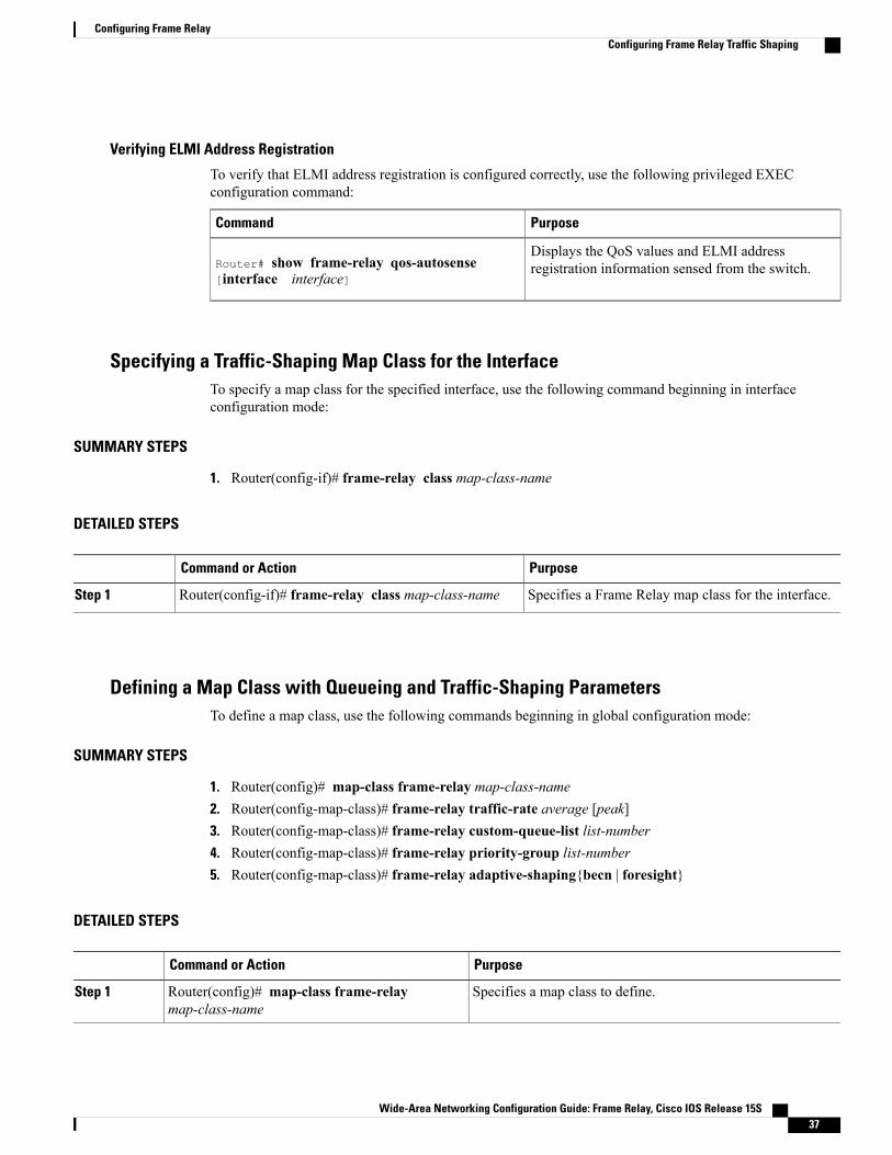
Verifying ELMI Address Registration
To verify that ELMI address registration is configured correctly, use the following privileged EXECconfiguration command:
PurposeCommand
Displays the QoS values and ELMI addressregistration information sensed from the switch.Router# show frame-relay qos-autosense
[interface interface]
Specifying a Traffic-Shaping Map Class for the InterfaceTo specify a map class for the specified interface, use the following command beginning in interfaceconfiguration mode:
SUMMARY STEPS
1. Router(config-if)# frame-relay class map-class-name
DETAILED STEPS
PurposeCommand or Action
Specifies a Frame Relay map class for the interface.Router(config-if)# frame-relay class map-class-nameStep 1
Defining a Map Class with Queueing and Traffic-Shaping ParametersTo define a map class, use the following commands beginning in global configuration mode:
SUMMARY STEPS
1. Router(config)# map-class frame-relay map-class-name2. Router(config-map-class)# frame-relay traffic-rate average [peak]3. Router(config-map-class)# frame-relay custom-queue-list list-number4. Router(config-map-class)# frame-relay priority-group list-number5. Router(config-map-class)# frame-relay adaptive-shaping{becn | foresight}
DETAILED STEPS
PurposeCommand or Action
Specifies a map class to define.Router(config)# map-class frame-relaymap-class-name
Step 1
Wide-Area Networking Configuration Guide: Frame Relay, Cisco IOS Release 15S 37
Configuring Frame RelayConfiguring Frame Relay Traffic Shaping

PurposeCommand or Action
Defines the traffic rate for the map class.Router(config-map-class)# frame-relay traffic-rateaverage [peak]
Step 2
Specifies a custom queue list.Router(config-map-class)# frame-relaycustom-queue-list list-number
Step 3
Specifies a priority queue list.Router(config-map-class)# frame-relaypriority-group list-number
Step 4
Selects BECN or ForeSight as congestion backward-notificationmechanism to which traffic shaping adapts.
Router(config-map-class)# frame-relayadaptive-shaping{becn | foresight}
Step 5
This command replaces the frame-relaybecn-response-enable command, which will beremoved in a future Cisco IOS release. If you use theframe-relay becn-response-enable command inscripts, you should replace it with the frame-relayadaptive-shaping software command.
Note
Configuring Frame Relay Switching
Enabling Frame Relay SwitchingYou must enable packet switching before you can configure it on a Frame Relay DTE or DCE, or withNetwork-to-Network Interface (NNI) support. Do so by using the following command in global configurationmode before configuring the switch type:
PurposeCommand
Enables Frame Relay switching.Router(config)# frame-relay switching
Configuring a Frame Relay DTE Device or DCE Switch or NNI SupportYou can configure an interface as a DTE device or a DCE switch, or as a switch connected to a switch tosupport NNI connections. (DTE is the default.) To do so, use the following command in interface configurationmode:
PurposeCommand
Configures a Frame Relay DTE device or DCEswitch.Router(config-if)# frame-relay intf-type [dce
| dte | nni]
Wide-Area Networking Configuration Guide: Frame Relay, Cisco IOS Release 15S38
Configuring Frame RelayConfiguring Frame Relay Switching

Creating Switched PVC over ISDNTo create a switched PVC over ISDN, or to create a switched PVC on which traffic shaping, traffic policing,and congestion management can be configured, use the following command in global configuration mode:
PurposeCommand
Defines connections between Frame Relay PVCs.Router(config)# connect connection-nameinterface dlci interface dlci
Creating a Switched PVC with Static Route
Static routes cannot be configured over tunnel interfaces on the Cisco 800 series, 1600 series, and 1700series platforms. Static routes can only be configured over tunnel interfaces on platforms that have theEnterprise feature set.
Note
To create a switched PVC with a static route, use the following command in interface configuration mode:
PurposeCommand
Specifies a static route for PVC switching.Router(config-if)# frame-relay route in-dlciinterface out-interface-type out-interface-numberout-dlci
Identifying a PVC As SwitchedBefore you can associate a map class with a switched PVC, you must identify the PVC as being switched. Toidentify a PVC as switched, use the following command in interface configuration mode:
PurposeCommand
Identifies a PVC as switched.Router(config-if)# frame-relay interface-dlcidlci switched
Wide-Area Networking Configuration Guide: Frame Relay, Cisco IOS Release 15S 39
Configuring Frame RelayConfiguring Frame Relay Switching

Configuring Traffic Policing on UNI DCE Devices
Enabling Frame Relay Policing
To enable Frame Relay policing on a interface, use the following command in interface configuration mode:
PurposeCommand
Enables Frame Relay policing on all switched PVCson the interface.Router(config-if)# frame-relay policing
Configuring Frame Relay Policing Parameters
To configure policing parameters in a Frame Relay map class, use one or more of the following commandsin map-class configuration mode:
PurposeCommand
Sets the CIR for a Frame Relay PVC, in bits persecond.Router(config-map-class)# frame-relay cir {in
| out} bps
Sets the committed burst size for a Frame Relay PVC,in bits.Router(config-map-class)# frame-relay bc {in
| out} bits
Sets the excess burst size for a Frame Relay PVC, inbits.Router(config-map-class)# frame-relay be {in
| out} bits
Sets the measurement interval for policing incomingtraffic on a PVC when the CIR is zero, inmilliseconds.
Router(config-map-class)# frame-relay tcmilliseconds
Configuring Congestion Management on Switched PVCs
Configuring Frame Relay Congestion Management on the Interface
To configure Frame Relay congestion management on all switched PVCs on an interface, use the followingcommands beginning in interface configuration mode:
SUMMARY STEPS
1. Router(config-if)# frame-relay congestion management2. Router(config-fr-congest)# threshold de percentage3. Router(config-fr-congest)# threshold ecn {bc | be} percentage
Wide-Area Networking Configuration Guide: Frame Relay, Cisco IOS Release 15S40
Configuring Frame RelayConfiguring Frame Relay Switching

DETAILED STEPS
PurposeCommand or Action
Enables Frame Relay congestion management on all switched PVCson an interface and enters Frame Relay congestion managementconfiguration mode.
Router(config-if)# frame-relay congestionmanagement
Step 1
Configures the threshold at which DE-marked packets will bediscarded from switched PVCs on the output interface.
Router(config-fr-congest)# threshold depercentage
Step 2
Configures the threshold at which ECN bits will be set on packetsin switched PVCs on the output interface.
Router(config-fr-congest)# threshold ecn {bc| be} percentage
Step 3
Configuring Frame Relay Congestion Management on Traffic-Shaping Queues
To configure Frame Relay congestion management on the traffic-shaping queues of switched PVCs, use oneor more of the following commands in map-class configuration mode:
PurposeCommand
Configures the threshold at whichDE-marked packetswill be discarded from the traffic-shaping queue of aswitched PVC.
Router(config-map-class)# frame-relaycongestion threshold de percentage
Configures the threshold at which ECN bits will beset on packets in the traffic-shaping queue of aswitched PVC.
Router(config-map-class)# frame-relaycongestion threshold ecn percentage
Configures the maximum size of a traffic-shapingqueue on a switched PVC.Router(config-map-class)# frame-relay holdq
queue-size
Configuring FRF.12 Fragmentation on Switched PVCsTo configure FRF.12 on switched PVCs, use the following map-class configuration command. The map classcan be associated with one or more switched PVCs.
PurposeCommand
Enables FRF.12 fragmentation on switched FrameRelay PVCs for a Frame Relay map class.Router(config-map-class)# frame-relay
fragment fragment_size switched
Wide-Area Networking Configuration Guide: Frame Relay, Cisco IOS Release 15S 41
Configuring Frame RelayConfiguring Frame Relay Switching

Verifying Frame Relay SwitchingTo verify the correct configuration of Frame Relay switching, use one or more of the following commands:
PurposeCommand
Displays statistics about Frame Relay fragmentation.Router# show frame-relay fragment [interfaceinterface] [dlci]
Displays statistics about FrameRelay PVCs includingdetailed reasons for packet drops on switched PVCsand complete status information for switched NNIPVCs.
Router# show frame-relay pvc [interfaceinterface] [dlci]
Displays information about the configuration andqueue at the interface.Router# show interfaces [type number]
Troubleshooting Frame Relay SwitchingTo diagnose problems in switched Frame Relay networks, use the following EXEC commands:
PurposeCommand
Displays debug messages for switched Frame RelayPVCs. The interval keyword and seconds argumentsets the interval at which the debug messages will bedisplayed.
Router# debug frame-relay switching [interfaceinterface] [dlci] [interval seconds]
Displays statistics about FrameRelay PVCs, includingdetailed reasons for packet drops on switched PVCsand complete status information for switched NNIPVCs.
Router# show frame-relay pvc [interfaceinterface] [dlci]
Customizing Frame Relay for Your Network
Configuring Frame Relay End-to-End Keepalives
Configuring End-to-End Keepalives
To configure FrameRelay end-to-end keepalives, use the following commands beginning in global configurationmode:
Wide-Area Networking Configuration Guide: Frame Relay, Cisco IOS Release 15S42
Configuring Frame RelayCustomizing Frame Relay for Your Network
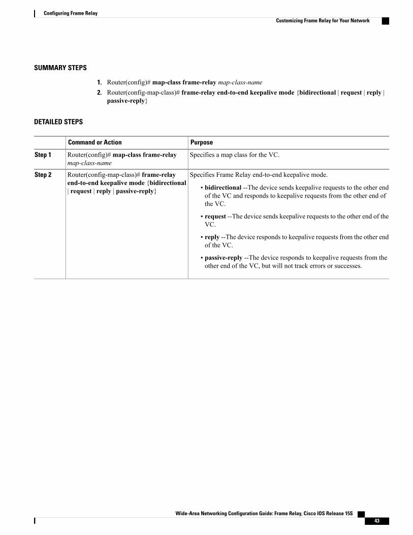
SUMMARY STEPS
1. Router(config)#map-class frame-relay map-class-name2. Router(config-map-class)# frame-relay end-to-end keepalive mode {bidirectional | request | reply |
passive-reply}
DETAILED STEPS
PurposeCommand or Action
Specifies a map class for the VC.Router(config)#map-class frame-relaymap-class-name
Step 1
Specifies Frame Relay end-to-end keepalive mode.Router(config-map-class)# frame-relayend-to-end keepalive mode {bidirectional| request | reply | passive-reply}
Step 2
• bidirectional --The device sends keepalive requests to the other endof the VC and responds to keepalive requests from the other end ofthe VC.
• request --The device sends keepalive requests to the other end of theVC.
• reply --The device responds to keepalive requests from the other endof the VC.
• passive-reply --The device responds to keepalive requests from theother end of the VC, but will not track errors or successes.
Wide-Area Networking Configuration Guide: Frame Relay, Cisco IOS Release 15S 43
Configuring Frame RelayCustomizing Frame Relay for Your Network

Modifying the Default Parameters
You can modify the end-to-end keepalives default parameter values by using any of the following map-classconfiguration commands:
PurposeCommand
Modifies the number of errors needed to change thekeepalive state from up to down.Router(config-map-class)# frame-relay
end-to-end keepalive error-threshold {send |receive} count
Modifies the number of recent events to be checkedfor errors.Router(config-map-class)# frame-relay
end-to-end keepalive event-window {send |receive} count
Modifies the number of consecutive success eventsrequired to change the keepalive state from down toup.
Router(config-map-class)# frame-relayend-to-end keepalive success-events {send |receive} count
Modifies the timer interval.Router(config-map-class)# frame-relayend-to-end keepalive timer {send | receive}interval
Verifying Frame Relay End-to-End Keepalives
Tomonitor the status of FrameRelay end-to-end keepalives, use the following command in EXEC configurationmode:
PurposeCommand
Shows the status of Frame Relay end-to-endkeepalives.Router# show frame-relay end-to-end keepalive
interface
Enabling PPP over Frame RelayTo configure the physical interface that will carry the PPP session and link it to the appropriate virtual templateinterface, perform the following task in interface configuration mode:
PurposeCommand
Defines the PVC and maps it to the virtual template.Router(config-if)# frame-relay interface-dlcidlci [ppp virtual-template-name]
Wide-Area Networking Configuration Guide: Frame Relay, Cisco IOS Release 15S44
Configuring Frame RelayCustomizing Frame Relay for Your Network
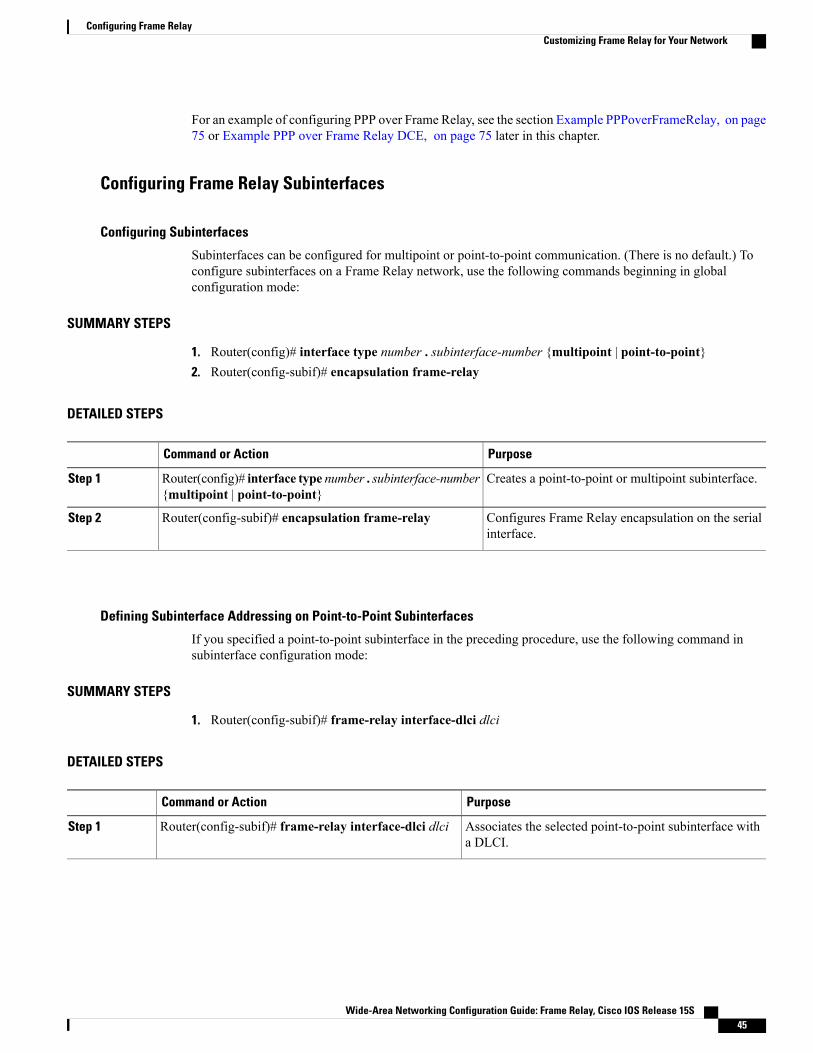
For an example of configuring PPP over Frame Relay, see the section Example PPPoverFrameRelay, on page75 or Example PPP over Frame Relay DCE, on page 75 later in this chapter.
Configuring Frame Relay Subinterfaces
Configuring Subinterfaces
Subinterfaces can be configured for multipoint or point-to-point communication. (There is no default.) Toconfigure subinterfaces on a Frame Relay network, use the following commands beginning in globalconfiguration mode:
SUMMARY STEPS
1. Router(config)# interface type number . subinterface-number {multipoint | point-to-point}2. Router(config-subif)# encapsulation frame-relay
DETAILED STEPS
PurposeCommand or Action
Creates a point-to-point or multipoint subinterface.Router(config)# interface type number . subinterface-number{multipoint | point-to-point}
Step 1
Configures Frame Relay encapsulation on the serialinterface.
Router(config-subif)# encapsulation frame-relayStep 2
Defining Subinterface Addressing on Point-to-Point Subinterfaces
If you specified a point-to-point subinterface in the preceding procedure, use the following command insubinterface configuration mode:
SUMMARY STEPS
1. Router(config-subif)# frame-relay interface-dlci dlci
DETAILED STEPS
PurposeCommand or Action
Associates the selected point-to-point subinterface witha DLCI.
Router(config-subif)# frame-relay interface-dlci dlciStep 1
Wide-Area Networking Configuration Guide: Frame Relay, Cisco IOS Release 15S 45
Configuring Frame RelayCustomizing Frame Relay for Your Network

Accepting Inverse ARP for Dynamic Address Mapping on Multipoint Subinterfaces
To associate a specific multipoint subinterface with a specific DLCI, use the following command in interfaceconfiguration mode:
PurposeCommand
Associates a specified multipoint subinterface with aDLCI.Router(config-if)# frame-relay interface-dlci
dlci
Configuring Static Address Mapping on Multipoint Subinterfaces
To establish static mapping according to your network needs, use one of the following commands in interfaceconfiguration mode:
PurposeCommand
Maps between a next-hop protocol address and DLCIdestination address.
The supported protocols and the correspondingkeywords to enable them are as follows:
• IP--ip
• DECnet--decnet
• AppleTalk--appletalk
• XNS--xns
• Novell IPX--ipx
• VINES--vines
• ISO CLNS--clns
Router(config-if)# frame-relay map protocolprotocol-address dlci [broadcast] [ietf] [cisco]
Defines a DLCI used to send ISO CLNS frames. Thebroadcast keyword is required for routing protocolssuch as OSI protocols and the Open Shortest PathFirst (OSPF) protocol.
Router(config-if)# frame-relay map clns dlci[broadcast]
Defines a DLCI destination bridge.Router(config-if)# frame-relay map bridgedlci [broadcast] [ietf]
Wide-Area Networking Configuration Guide: Frame Relay, Cisco IOS Release 15S46
Configuring Frame RelayCustomizing Frame Relay for Your Network

Configuring Transparent Bridging for Point-to-Point Subinterfaces
All PVCs configured on a subinterface belong to the same bridge group.Note
To configure transparent bridging for point-to-point subinterfaces, use the following commands beginning inglobal configuration mode:
SUMMARY STEPS
1. Router(config)# interface type number2. Router(config-if)# encapsulation frame-relay3. Router(config)# interface type number : subinterface-number point-to-point4. Router(config-subif)# frame-relay interface-dlci dlci5. Router(config-subif)# bridge-group bridge-group
DETAILED STEPS
PurposeCommand or Action
Specifies an interface.Router(config)# interface type numberStep 1
Configures Frame Relay encapsulation on theinterface.
Router(config-if)# encapsulation frame-relayStep 2
Specifies a subinterface.Router(config)# interface type number :subinterface-number point-to-point
Step 3
Associates a DLCI with the subinterface.Router(config-subif)# frame-relay interface-dlci dlciStep 4
Associates the subinterface with a bridge group.Router(config-subif)# bridge-group bridge-groupStep 5
Configuring Transparent Bridging for Point-to-Multipoint Interfaces
All PVCs configured on a subinterface belong to the same bridge group.Note
To configure transparent bridging for point-to-multipoint subinterfaces, use the following commands beginningin global configuration mode:
Wide-Area Networking Configuration Guide: Frame Relay, Cisco IOS Release 15S 47
Configuring Frame RelayCustomizing Frame Relay for Your Network

SUMMARY STEPS
1. Router(config)# interface type number2. Router(config-if)# encapsulation frame-relay3. Router(config)# interface typenumber:subinterface-number multipoint4. Router(config-subif)# frame-relay map bridge dlci [broadcast] [ietf]5. Router(config-subif)# bridge-group bridge-group
DETAILED STEPS
PurposeCommand or Action
Specifies an interface.Router(config)# interface type numberStep 1
Configures Frame Relay encapsulation.Router(config-if)# encapsulation frame-relayStep 2
Specifies a subinterface.Router(config)# interface typenumber:subinterface-numbermultipoint
Step 3
Defines a DLCI destination bridge.Router(config-subif)# frame-relay map bridge dlci[broadcast] [ietf]
Step 4
Associates the subinterface with a bridge group.Router(config-subif)# bridge-group bridge-groupStep 5
Configuring a Backup Interface for a Subinterface
To configure a backup interface for a Frame Relay subinterface, use the following commands beginning inglobal configuration mode:
SUMMARY STEPS
1. Router(config)# interface type number2. Router(config-if)# encapsulation frame-relay3. Router(config)# interface type number . subinterface-number point-to-point4. Router(config-subif)# frame-relay interface-dlci dlci5. Router(config-subif)# backup interface type number6. Router(config-subif)# backup delay enable-delay disable-delay
DETAILED STEPS
PurposeCommand or Action
Specifies the interface.Router(config)# interface type numberStep 1
Configures Frame Relay encapsulation.Router(config-if)# encapsulation frame-relayStep 2
Wide-Area Networking Configuration Guide: Frame Relay, Cisco IOS Release 15S48
Configuring Frame RelayCustomizing Frame Relay for Your Network

PurposeCommand or Action
Configures the subinterface.Router(config)# interface type number . subinterface-numberpoint-to-point
Step 3
Specifies DLCI for the subinterface.Router(config-subif)# frame-relay interface-dlci dlciStep 4
Configures backup interface for the subinterface.Router(config-subif)# backup interface type numberStep 5
Specifies backup enable and disable delay.Router(config-subif)# backup delay enable-delaydisable-delay
Step 6
Disabling or Reenabling Frame Relay Inverse ARPTo select or disable Inverse ARP, use one of the following commands in interface configuration mode:
PurposeCommand
Enables Frame Relay Inverse ARP for a specificprotocol and DLCI pair, only if it was previouslydisabled.
frame-relay inverse-arp protocol dlci
Disables Frame Relay Inverse ARP for a specificprotocol and DLCI pair.
no frame relay inverse-arp protocol dlci
Creating a Broadcast Queue for an InterfaceTo create a broadcast queue, use the following command in interface configuration mode:
PurposeCommand
Creates a broadcast queue for an interface.Router(config-if)# frame-relay broadcast-queuesize byte-rate packet-rate
Configuring Frame Relay Fragmentation
Configuring End-to-End FRF.12 Fragmentation
To configure FRF.12 fragmentation in a Frame Relay map class, use the following commands beginning inglobal configuration mode:
Wide-Area Networking Configuration Guide: Frame Relay, Cisco IOS Release 15S 49
Configuring Frame RelayCustomizing Frame Relay for Your Network
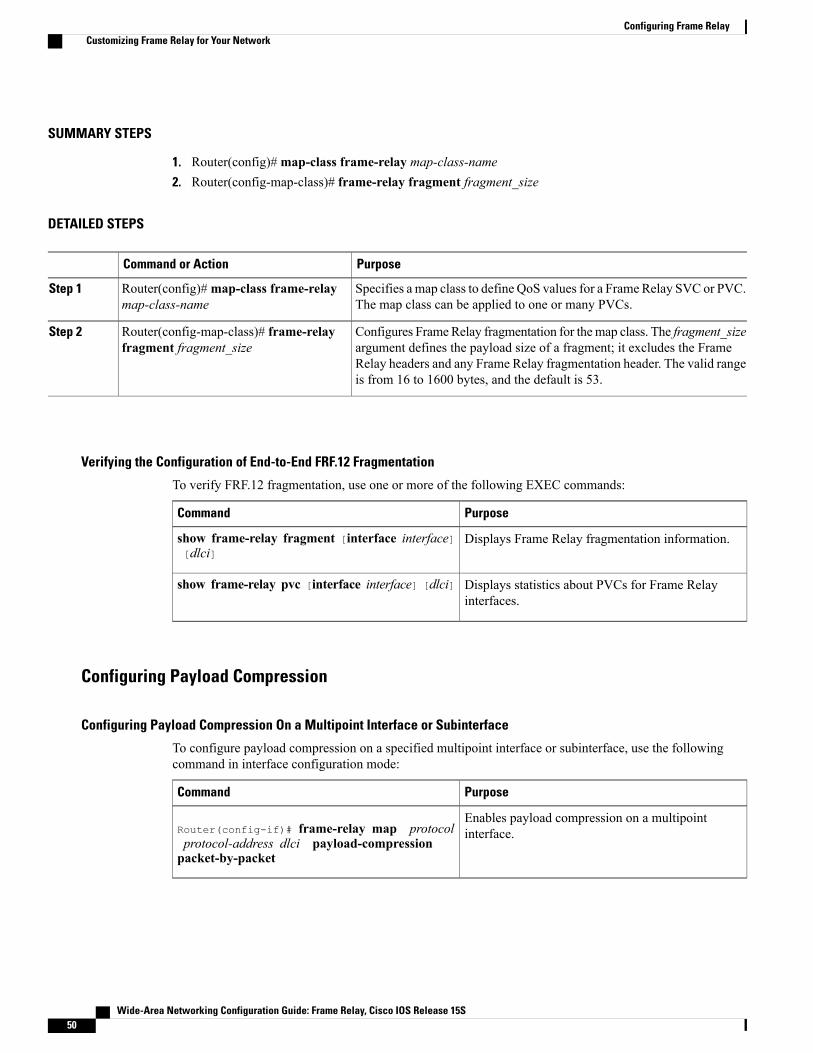
SUMMARY STEPS
1. Router(config)#map-class frame-relay map-class-name2. Router(config-map-class)# frame-relay fragment fragment_size
DETAILED STEPS
PurposeCommand or Action
Specifies a map class to define QoS values for a Frame Relay SVC or PVC.The map class can be applied to one or many PVCs.
Router(config)#map-class frame-relaymap-class-name
Step 1
Configures FrameRelay fragmentation for themap class. The fragment_sizeargument defines the payload size of a fragment; it excludes the Frame
Router(config-map-class)# frame-relayfragment fragment_size
Step 2
Relay headers and any Frame Relay fragmentation header. The valid rangeis from 16 to 1600 bytes, and the default is 53.
Verifying the Configuration of End-to-End FRF.12 Fragmentation
To verify FRF.12 fragmentation, use one or more of the following EXEC commands:
PurposeCommand
Displays Frame Relay fragmentation information.show frame-relay fragment [interface interface][dlci]
Displays statistics about PVCs for Frame Relayinterfaces.
show frame-relay pvc [interface interface] [dlci]
Configuring Payload Compression
Configuring Payload Compression On a Multipoint Interface or Subinterface
To configure payload compression on a specified multipoint interface or subinterface, use the followingcommand in interface configuration mode:
PurposeCommand
Enables payload compression on a multipointinterface.Router(config-if)# frame-relay map protocol
protocol-address dlci payload-compressionpacket-by-packet
Wide-Area Networking Configuration Guide: Frame Relay, Cisco IOS Release 15S50
Configuring Frame RelayCustomizing Frame Relay for Your Network

Configuring Payload Compression On a Point-to-Point Interface or Subinterface
To configure payload compression on a specified point-to-point interface or subinterface, use the followingcommand in interface configuration mode:
PurposeCommand
Enables payload compression on a point-to-pointinterface.Router(config-if)# frame-relay
payload-compression packet-by-packet
Configuring FRF.9 Compression Using Map Statements
You can control where you want compression to occur by specifying an interface. To enable FRF.9 compressionon a specific CSA, VIP CPU, or host CPU, use the following commands beginning in global configurationmode:
SUMMARY STEPS
1. Router(config)# interface type number2. Router(config-if)# encapsulation frame-relay3. Router(config-if)# frame-relay map payload-compression frf9 stac[hardware-options]
DETAILED STEPS
PurposeCommand or Action
Specifies the interface.Router(config)# interface type numberStep 1
Specifies Frame Relay as encapsulation type.Router(config-if)# encapsulation frame-relayStep 2
Enables FRF.9 compression.Router(config-if)# frame-relay map payload-compressionfrf9 stac[hardware-options]
Step 3
Configuring FRF.9 Compression on the Subinterface
To configure FRF.9 compression on the subinterface, use the following commands beginning in globalconfiguration mode:
SUMMARY STEPS
1. Router(config)# interface type number2. Router(config-subif)# encapsulation frame-relay3. Router(config-subif)# frame-relay payload-compression frf9 stac[hardware-options]
Wide-Area Networking Configuration Guide: Frame Relay, Cisco IOS Release 15S 51
Configuring Frame RelayCustomizing Frame Relay for Your Network
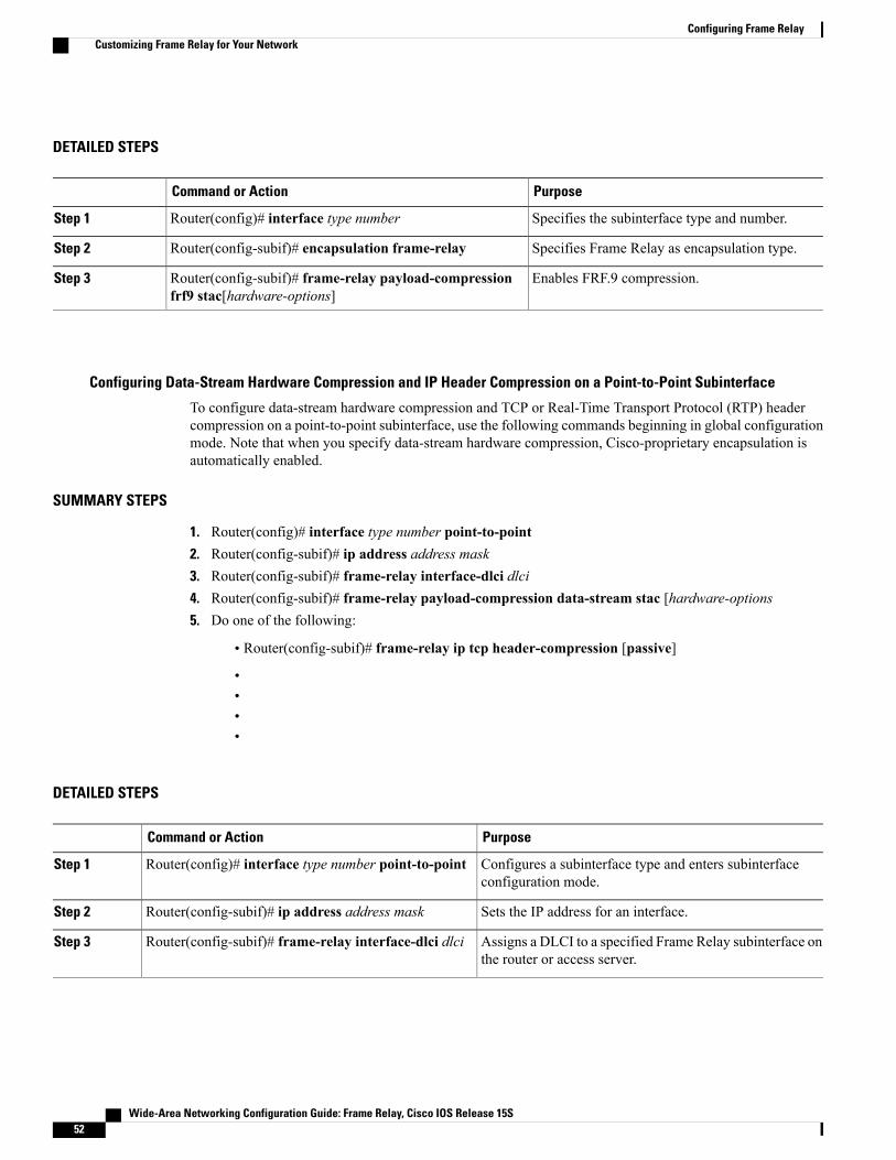
DETAILED STEPS
PurposeCommand or Action
Specifies the subinterface type and number.Router(config)# interface type numberStep 1
Specifies Frame Relay as encapsulation type.Router(config-subif)# encapsulation frame-relayStep 2
Enables FRF.9 compression.Router(config-subif)# frame-relay payload-compressionfrf9 stac[hardware-options]
Step 3
Configuring Data-Stream Hardware Compression and IP Header Compression on a Point-to-Point Subinterface
To configure data-stream hardware compression and TCP or Real-Time Transport Protocol (RTP) headercompression on a point-to-point subinterface, use the following commands beginning in global configurationmode. Note that when you specify data-stream hardware compression, Cisco-proprietary encapsulation isautomatically enabled.
SUMMARY STEPS
1. Router(config)# interface type number point-to-point2. Router(config-subif)# ip address address mask3. Router(config-subif)# frame-relay interface-dlci dlci4. Router(config-subif)# frame-relay payload-compression data-stream stac [hardware-options5. Do one of the following:
• Router(config-subif)# frame-relay ip tcp header-compression [passive]
••••
DETAILED STEPS
PurposeCommand or Action
Configures a subinterface type and enters subinterfaceconfiguration mode.
Router(config)# interface type number point-to-pointStep 1
Sets the IP address for an interface.Router(config-subif)# ip address address maskStep 2
Assigns a DLCI to a specified Frame Relay subinterface onthe router or access server.
Router(config-subif)# frame-relay interface-dlci dlciStep 3
Wide-Area Networking Configuration Guide: Frame Relay, Cisco IOS Release 15S52
Configuring Frame RelayCustomizing Frame Relay for Your Network

PurposeCommand or Action
Enables hardware compression on an interface orsubinterface that uses Cisco-proprietary encapsulation.
Router(config-subif)# frame-relay payload-compressiondata-stream stac [hardware-options
Step 4
Configures an interface to ensure that the associated PVCscarry outgoing TCP headers in compressed form.
Do one of the following:Step 5
• Router(config-subif)# frame-relay ip tcpheader-compression [passive]
• Enables RTP header compression on the physical interface.•••
Example:
Router(config-subif)#frame-relay ip rtp header-compression [passive]
Configuring Data-Stream Hardware Compression and IP Header Compression on a Multipoint Subinterface
To configure data-stream hardware compression and TCP or RTP header compression on a multipointsubinterface, use the following commands beginning in global configurationmode. Note that when you specifydata-stream hardware compression, Cisco-proprietary encapsulation is automatically enabled.
SUMMARY STEPS
1. Router(config)# interface type numbermultipoint2. Router(config-subif)# frame-relay interface-dlci dlci3. Router(config-subif)# frame-relaymap protocol protocol-address dlci [payload-compression data-stream
stac [hardware-options]]4. Do one of the following:
• Router(config-subif)# frame-relay ip tcp header-compression [passive]
••••
Wide-Area Networking Configuration Guide: Frame Relay, Cisco IOS Release 15S 53
Configuring Frame RelayCustomizing Frame Relay for Your Network

DETAILED STEPS
PurposeCommand or Action
Configures a subinterface type and enters subinterfaceconfiguration mode.
Router(config)# interface type numbermultipointStep 1
Assigns a DLCI to a specified Frame Relay subinterface onthe router or access server.
Router(config-subif)# frame-relay interface-dlci dlciStep 2
Defines the mapping between a destination protocol addressand the DLCI used to connect to the destination address onan interface that uses Cisco-proprietary encapsulation.
Router(config-subif)# frame-relay map protocolprotocol-address dlci [payload-compressiondata-stream stac [hardware-options]]
Step 3
Configures an interface to ensure that the associated PVCscarry outgoing TCP headers in compressed form.
Do one of the following:Step 4
• Router(config-subif)# frame-relay ip tcpheader-compression [passive]
• Enables RTP header compression on the physical interface.•••
Example:
Router(config-subif)#frame-relay ip rtp header-compression [passive]
Verifying Payload Compression
To verify that payload compression is working correctly, use the following privileged EXEC commands:
PurposeCommand
Displays compression statistics.Router# show compress
Displays statistics about PVCs for Frame Relayinterfaces, including the number of packets in thepost-hardware-compression queue.
Router# show frame-relay pvc dlci
Displays information about the elements queued at aparticular time at the DLCI level, including thenumber of packets in the post-hardware- compressionqueue.
Router# show traffic-shape queue
Wide-Area Networking Configuration Guide: Frame Relay, Cisco IOS Release 15S54
Configuring Frame RelayCustomizing Frame Relay for Your Network
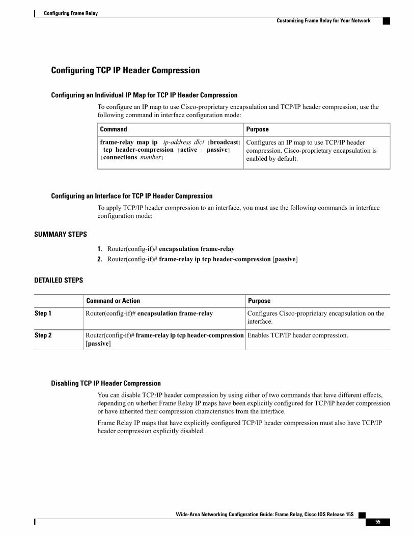
Configuring TCP IP Header Compression
Configuring an Individual IP Map for TCP IP Header Compression
To configure an IP map to use Cisco-proprietary encapsulation and TCP/IP header compression, use thefollowing command in interface configuration mode:
PurposeCommand
Configures an IP map to use TCP/IP headercompression. Cisco-proprietary encapsulation isenabled by default.
frame-relay map ip ip-address dlci [broadcast]tcp header-compression [active | passive][connections number]
Configuring an Interface for TCP IP Header Compression
To apply TCP/IP header compression to an interface, you must use the following commands in interfaceconfiguration mode:
SUMMARY STEPS
1. Router(config-if)# encapsulation frame-relay2. Router(config-if)# frame-relay ip tcp header-compression [passive]
DETAILED STEPS
PurposeCommand or Action
Configures Cisco-proprietary encapsulation on theinterface.
Router(config-if)# encapsulation frame-relayStep 1
Enables TCP/IP header compression.Router(config-if)# frame-relay ip tcp header-compression[passive]
Step 2
Disabling TCP IP Header Compression
You can disable TCP/IP header compression by using either of two commands that have different effects,depending on whether Frame Relay IP maps have been explicitly configured for TCP/IP header compressionor have inherited their compression characteristics from the interface.
Frame Relay IP maps that have explicitly configured TCP/IP header compression must also have TCP/IPheader compression explicitly disabled.
Wide-Area Networking Configuration Guide: Frame Relay, Cisco IOS Release 15S 55
Configuring Frame RelayCustomizing Frame Relay for Your Network

To disable TCP/IP header compression, use one of the following commands in interface configuration mode:
PurposeCommand
Disables TCP/IP header compression on all FrameRelay IP maps that are not explicitly configured forTCP header compression.
no frame-relay ip tcp header-compression
Disables RTP and TCP/IP header compression on aspecified Frame Relay IP map.
frame-relay map ip ip-address dlci nocompress
Configuring Discard Eligibility
Defining a DE List
To define a DE list specifying the packets that can be dropped when the Frame Relay switch is congested,use the following command in global configuration mode:
SUMMARY STEPS
1. Router(config)# frame-relay de-list list-number {protocol protocol | interface type number}characteristic
DETAILED STEPS
PurposeCommand or Action
Defines a DE list.Router(config)# frame-relay de-list list-number {protocol protocol |interface type number} characteristic
Step 1
Defining a DE Group
To define a DE group specifying the DE list and DLCI affected, use the following command in interfaceconfiguration mode:
PurposeCommand
Defines a DE group.frame-relay de-group group-number dlci
Wide-Area Networking Configuration Guide: Frame Relay, Cisco IOS Release 15S56
Configuring Frame RelayCustomizing Frame Relay for Your Network
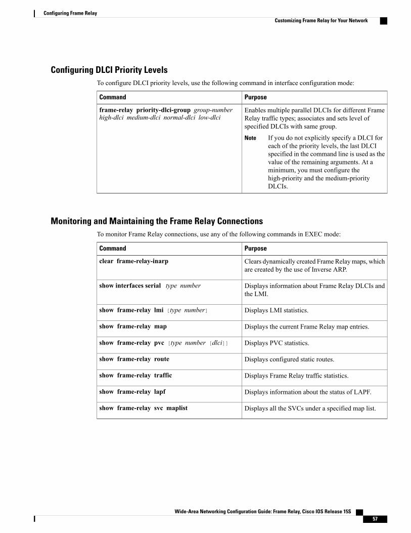
Configuring DLCI Priority LevelsTo configure DLCI priority levels, use the following command in interface configuration mode:
PurposeCommand
Enables multiple parallel DLCIs for different FrameRelay traffic types; associates and sets level ofspecified DLCIs with same group.
If you do not explicitly specify a DLCI foreach of the priority levels, the last DLCIspecified in the command line is used as thevalue of the remaining arguments. At aminimum, you must configure thehigh-priority and the medium-priorityDLCIs.
Note
frame-relay priority-dlci-group group-numberhigh-dlci medium-dlci normal-dlci low-dlci
Monitoring and Maintaining the Frame Relay ConnectionsTo monitor Frame Relay connections, use any of the following commands in EXEC mode:
PurposeCommand
Clears dynamically created Frame Relaymaps, whichare created by the use of Inverse ARP.
clear frame-relay-inarp
Displays information about Frame Relay DLCIs andthe LMI.
show interfaces serial type number
Displays LMI statistics.show frame-relay lmi [type number]
Displays the current Frame Relay map entries.show frame-relay map
Displays PVC statistics.show frame-relay pvc [type number [dlci]]
Displays configured static routes.show frame-relay route
Displays Frame Relay traffic statistics.show frame-relay traffic
Displays information about the status of LAPF.show frame-relay lapf
Displays all the SVCs under a specified map list.show frame-relay svc maplist
Wide-Area Networking Configuration Guide: Frame Relay, Cisco IOS Release 15S 57
Configuring Frame RelayCustomizing Frame Relay for Your Network

Configuration Examples for Frame Relay
Example IETF Encapsulation
Example IETF Encapsulation on the InterfaceThe following example sets IETF encapsulation at the interface level. The keyword ietf sets the defaultencapsulation method for all maps to IETF.encapsulation frame-relay ietfframe-relay map ip 131.108.123.2 48 broadcastframe-relay map ip 131.108.123.3 49 broadcast
Example IETF Encapsulation on a Per-DLCI BasisThe following example configures IETF encapsulation on a per-DLCI basis. This configuration has the sameresult as the configuration in the first example.encapsulation frame-relayframe-relay map ip 131.108.123.2 48 broadcast ietfframe-relay map ip 131.108.123.3 49 broadcast ietf
Example Static Address Mapping
Example Two Routers in Static ModeThe following example shows how to configure two routers for static mode:
Configuration for Router 1interface serial0ip address 131.108.64.2 255.255.255.0encapsulation frame-relaykeepalive 10frame-relay map ip 131.108.64.1 43
Configuration for Router 2interface serial1ip address 131.108.64.1 255.255.255.0encapsulation frame-relaykeepalive 10frame-relay map ip 131.108.64.2 43
Example AppleTalk RoutingThe following example shows how to configure two routers to communicate with each other using AppleTalkover a Frame Relay network. Each router has a Frame Relay static address map for the other router. The useof the appletalk cable-range command indicates that this is extended AppleTalk (Phase II).
Wide-Area Networking Configuration Guide: Frame Relay, Cisco IOS Release 15S58
Configuring Frame RelayConfiguration Examples for Frame Relay

Configuration for Router 1
interface serial0ip address 172.21.59.24 255.255.255.0encapsulation frame-relayappletalk cable-range 10-20 18.47appletalk zone engframe-relay map appletalk 18.225 100 broadcast
Configuration for Router 2
interface serial2/3ip address 172.21.177.18 255.255.255.0encapsulation frame-relayappletalk cable-range 10-20 18.225appletalk zone engclockrate 2000000frame-relay map appletalk 18.47 100 broadcast
Example DECnet RoutingThe following example sends all DECnet packets destined for address 56.4 out on DLCI 101. In addition, anyDECnet broadcasts for interface serial 1 will be sent on that DLCI.
decnet routing 32.6!interface serial 1encapsulation frame-relayframe-relay map decnet 56.4 101 broadcast
Example IPX RoutingThe following example shows how to send packets destined for IPX address 200.0000.0c00.7b21 out on DLCI102:
ipx routing 000.0c00.7b3b!interface ethernet 0ipx network 2abc!interface serial 0ipx network 200encapsulation frame-relayframe-relay map ipx 200.0000.0c00.7b21 102 broadcast
Example Subinterface
Example Basic SubinterfaceIn the following example, subinterface 1 is configured as a point-to-point subnet and subinterface 2 is configuredas a multipoint subnet.interface serial 0encapsulation frame-relayinterface serial 0.1 point-to-pointip address 10.0.1.1 255.255.255.0frame-relay interface-dlci 42
Wide-Area Networking Configuration Guide: Frame Relay, Cisco IOS Release 15S 59
Configuring Frame RelayExample Subinterface

!interface serial 0.2 multipointip address 10.0.2.1 255.255.255.0frame-relay map ip 10.0.2.2 18
Example Frame Relay Multipoint Subinterface with Dynamic AddressingThe following example configures two multipoint subinterfaces for dynamic address resolution. Eachsubinterface is provided with an individual protocol address and subnet mask, and the frame-relayinterface-dlci command associates the subinterface with a specified DLCI. Addresses of remote destinationsfor each multipoint subinterface will be resolved dynamically.
interface serial0no ip addressencapsulation frame-relayframe-relay lmi-type ansi!interface serial0.103 multipointip address 172.21.177.18 255.255.255.0frame-relay interface-dlci 300!interface serial0.104 multipointip address 172.21.178.18 255.255.255.0frame-relay interface-dlci 400
Example IPX Routes over Frame Relay SubinterfacesThe following example configures a serial interface for Frame Relay encapsulation and sets up multiple IPXvirtual networks corresponding to Frame Relay subinterfaces:
ipx routing 0000.0c02.5f4f!interface serial 0encapsulation frame-relayinterface serial 0.1 multipointipx network 1frame-relay map ipx 1.000.0c07.d530 200 broadcastinterface serial 0.2 multipointipx network 2frame-relay map ipx 2.000.0c07.d530 300 broadcastFor subinterface serial 0.1, the router at the other end might be configured as follows:
ipx routinginterface serial 2 multipointipx network 1frame-relay map ipx 1.000.0c02.5f4f 200 broadcast
Example Unnumbered IP over a Point-to-Point SubinterfaceThe following example sets up unnumbered IP over subinterfaces at both ends of a point-to-point connection.In this example, router A functions as the DTE, and router B functions as the DCE. Routers A and B are bothattached to Token Ring networks.
Configuration for Router A
interface token-ring 0ip address 131.108.177.1 255.255.255.0!interface serial 0
Wide-Area Networking Configuration Guide: Frame Relay, Cisco IOS Release 15S60
Configuring Frame RelayExample Subinterface

no ip addressencapsulation frame-relay IETF!interface serial0.2 point-to-pointip unnumbered TokenRing0ip pim sparse-modeframe-relay interface-dlci 20
Configuration for Router B
frame-relay switching!interface token-ring 0ip address 131.108.178.1 255.255.255.0!interface serial 0no ip addressencapsulation frame-relay IETFbandwidth 384clockrate 4000000frame-relay intf-type dce!interface serial 0.2 point-to-pointip unnumbered TokenRing1ip pim sparse-mode!bandwidth 384frame-relay interface-dlci 20
Example Transparent Bridging Using SubinterfacesThe following example shows Frame Relay DLCIs 42, 64, and 73 as separate point-to-point links withtransparent bridging running over them. The bridging spanning tree views each PVC as a separate bridge port,and a frame arriving on the PVC can be relayed back out on a separate PVC.
interface serial 0encapsulation frame-relayinterface serial 0.1 point-to-pointbridge-group 1frame-relay interface-dlci 42interface serial 0.2 point-to-pointbridge-group 1frame-relay interface-dlci 64interface serial 0.3 point-to-pointbridge-group 1frame-relay interface-dlci 73
Example SVC Configuration
Example SVC InterfaceThe following example configures a physical interface, applies a map group to the physical interface, andthen defines the map group:
interface serial 0ip address 172.10.8.6encapsulation frame-relaymap-group bermudaframe-relay lmi-type q933aframe-relay svc
Wide-Area Networking Configuration Guide: Frame Relay, Cisco IOS Release 15S 61
Configuring Frame RelayExample SVC Configuration

!map-list bermuda source-addr E164 123456 dest-addr E164 654321ip 131.108.177.100 class hawaiiappletalk 1000.2 class rainbow!map-class frame-relay rainbowframe-relay idle-timer 60!map-class frame-relay hawaiiframe-relay cir in 64000frame-relay cir out 64000
Example SVC SubinterfaceThe following example configures a point-to-point interface for SVC operation. It assumes that the main serial0 interface has been configured for signalling and that SVC operation has been enabled on the main interface:
int s 0.1 point-point! Define the map-group; details are specified under the map-list holiday command.map-group holiday!! Associate the map-group with a specific source and destination.map-list holiday local-addr X121 <X121-addr> dest-addr E164 <E164-addr>! Specify destination protocol addresses for a map-class.ip 131.108.177.100 class hawaii IETFappletalk 1000.2 class rainbow IETF broadcast!! Define a map class and its QoS settings.map-class hawaiiframe-relay cir in 2000000frame-relay cir out 56000frame-relay be 9000!! Define another map class and its QoS settings.map-class rainbowframe-relay cir in 64000frame-relay idle-timer 2000
Example Frame Relay Traffic Shaping
Example Traffic Shaping with Three Point-to-Point SubinterfacesIn the following example, VCs on subinterfaces Serial0.1 and Serial0.2 inherit class parameters from the maininterface--namely, those defined in the map class "slow_vcs"--but the VC defined on subinterface Serial0.2(DLCI 102) is specifically configured to use map class "fast_vcs".
Map class "slow_vcs" uses a peak rate of 9600 and average rate of 4800 bps. Because BECN feedback isenabled, the output rate will be cut back to as low as 2400 bps in response to received BECNs. This map classis configured to use custom queueing using queue-list 1. In this example, queue-list 1 has 3 queues, with thefirst two being controlled by access lists 100 and 115.
Map class "fast_vcs" uses a peak rate of 64000 and average rate of 16000 bps. Because BECN feedback isenabled, the output rate will be cut back to as low as 8000 bps in response to received BECNs. This map classis configured to use priority-queueing using priority-group 2.
interface serial0no ip addressencapsulation frame-relayframe-relay lmi-type ansiframe-relay traffic-shaping
Wide-Area Networking Configuration Guide: Frame Relay, Cisco IOS Release 15S62
Configuring Frame RelayExample Frame Relay Traffic Shaping

frame-relay class slow_vcs!interface serial0.1 point-to-pointip address 10.128.30.1 255.255.255.248ip ospf cost 200bandwidth 10frame-relay interface-dlci 101!interface serial0.2 point-to-pointip address 10.128.30.9 255.255.255.248ip ospf cost 400bandwidth 10frame-relay interface-dlci 102class fast_vcs
!interface serial0.3 point-to-pointip address 10.128.30.17 255.255.255.248ip ospf cost 200bandwidth 10frame-relay interface-dlci 103!map-class frame-relay slow_vcsframe-relay traffic-rate 4800 9600frame-relay custom-queue-list 1frame-relay adaptive-shaping becn!map-class frame-relay fast_vcsframe-relay traffic-rate 16000 64000frame-relay priority-group 2frame-relay adaptive-shaping becn!access-list 100 permit tcp any any eq 2065access-list 115 permit tcp any any eq 256!priority-list 2 protocol decnet highpriority-list 2 ip normalpriority-list 2 default medium!queue-list 1 protocol ip 1 list 100queue-list 1 protocol ip 2 list 115queue-list 1 default 3queue-list 1 queue 1 byte-count 1600 limit 200queue-list 1 queue 2 byte-count 600 limit 200queue-list 1 queue 3 byte-count 500 limit 200
Example Traffic Shaping with ForeSightThe following example illustrates a router configuration with traffic shaping enabled. DLCIs 100 and 101 onsubinterfaces Serial 13.2 and Serial 13.3 inherit class parameters from the main interface. The traffic shapingfor these two VCs will be adaptive to the ForeSight notification.
For Serial 0, the output rate for DLCI 103 will not be affected by the router ForeSight function.
interface Serial0no ip addressencapsulation frame-relayframe-relay lmi-type ansiframe-relay traffic-shaping!interface Serial0.2 point-to-pointip address 10.128.30.17 255.255.255.248frame-relay interface-dlci 102class fast_vcs!interface Serial0.3 point-to-pointip address 10.128.30.5 255.255.255.248ip ospf cost 200frame-relay interface-dlci 103class slow_vcs
Wide-Area Networking Configuration Guide: Frame Relay, Cisco IOS Release 15S 63
Configuring Frame RelayExample Frame Relay Traffic Shaping

!interface serial 3no ip addressencapsulation frame-relayframe-relay traffic-shapingframe-relay class fast_vcs!interface Serial3.2 multipointip address 100.120.20.13 255.255.255.248frame-relay map ip 100.120.20.6 16 ietf broadcast!interface Serial3.3 point-to-pointip address 100.120.10.13 255.255.255.248frame-relay interface-dlci 101!map-class frame-relay slow_vcsframe-relay adaptive-shaping becnframe-relay traffic-rate 4800 9600!map-class frame-relay fast_vcsframe-relay adaptive-shaping foresightframe-relay traffic-rate 16000 64000frame-relay cir 56000frame-relay bc 64000
Example LMI Configuration
Example ELMI and Frame Relay Traffic Shaping
The following configuration shows a Frame Relay interface enabled with QoS autosense. The router receivesmessages from the Cisco switch, which is also configured with QoS autosense enabled. When ELMI isconfigured in conjunction with traffic shaping, the router will receive congestion information through BECNor router ForeSight congestion signalling and reduce its output rate to the value specified in the traffic shapingconfiguration.
interface serial0no ip addressencapsulation frame-relayframe-relay lmi-type ansiframe-relay traffic-shapingframe-relay QoS-autosense
!interface serial0.1 point-to-pointno ip addressframe-relay interface-dlci 101
Example Configuring the IP Address for ELMI Address Registration
The following example shows how to configure the IP address to be used for ELMI address registration.Automatic IP address selection is automatically disabled when the IP address is configured. ELMI is enabledon serial interface 0.
interface Serial 0no ip addressencapsulation frame-relayframe-relay lmi-type ansiframe-relay qos-autosense
!frame-relay address registration ip address 139.85.242.195!
Wide-Area Networking Configuration Guide: Frame Relay, Cisco IOS Release 15S64
Configuring Frame RelayExample Frame Relay Traffic Shaping

Example Disabling ELMI Address Registration on an Interface
In the following example, ELMI address registration is disabled on serial interface 0. This interface will sharean IP address of 0.0.0.0 and an ifIndex of 0. Automatic IP address selection is enabled by default when ELMIis enabled, so the management IP address of other interfaces on this router will be chosen automatically.
interface Serial 0no ip addressencapsulation frame-relayframe-relay lmi-type ansiframe-relay qos-autosenseno frame-relay address-reg-enable
!
Example Backward CompatibilityThe following configuration provides backward compatibility and interoperability with versions not compliantwith RFC 1490. The ietf keyword is used to generate RFC 1490 traffic. This configuration is possible becauseof the flexibility provided by separately defining each map entry.encapsulation frame-relayframe-relay map ip 131.108.123.2 48 broadcast ietf! interoperability is provided by IETF encapsulationframe-relay map ip 131.108.123.3 49 broadcast ietfframe-relay map ip 131.108.123.7 58 broadcast! this line allows the router to connect with a! device running an older version of softwareframe-relay map decnet 21.7 49 broadcast
Example Booting from a Network Server over Frame RelayWhen booting from a TFTP server over Frame Relay, you cannot boot from a network server via a broadcast.You must boot from a specific TFTP host. Also, a frame-relay map command must exist for the host fromwhich you will boot.
For example, if file "gs3-bfx" is to be booted from a host with IP address 131.108.126.2, the followingcommands would need to be in the configuration:boot system gs3-bfx 131.108.126.2!interface Serial 0encapsulation frame-relayframe-relay map IP 131.108.126.2 100 broadcastThe frame-relaymap command is used to map an IP address into a DLCI address. To boot over Frame Relay,you must explicitly give the address of the network server to boot from, and a frame-relay map entry mustexist for that site. For example, if file "gs3-bfx.83-2.0" is to be booted from a host with IP address131.108.126.111, the following commands must be in the configuration:boot system gs3-bfx.83-2.0 131.108.13.111!interface Serial 1ip address 131.108.126.200 255.255.255.0encapsulation frame-relayframe-relay map ip 131.108.126.111 100 broadcastIn this case, 100 is the DLCI that can get to host 131.108.126.111.
The remote router must be configured with the following command:frame-relay map ip 131.108.126.200 101 broadcast
Wide-Area Networking Configuration Guide: Frame Relay, Cisco IOS Release 15S 65
Configuring Frame RelayExample Backward Compatibility

This entry allows the remote router to return a boot image (from the network server) to the router bootingover Frame Relay. Here, 101 is a DLCI of the router being booted.
Example Frame Relay Switching
Example PVC Switching ConfigurationYou can configure your router as a dedicated, DCE-only Frame Relay switch. Switching is based on DLCIs.The incoming DLCI is examined, and the outgoing interface and DLCI are determined. Switching takes placewhen the incoming DLCI in the packet is replaced by the outgoing DLCI, and the packet is sent out theoutgoing interface.
In the figure below, the router switches two PVCs between serial interfaces 1 and 2. Frames with DLCI 100received on serial 1 will be transmitted with DLCI 200 on serial 2.
Figure 10: PVC Switching Configuration
The following example shows one router with two interfaces configured as DCEs. The router switches framesfrom the incoming interface to the outgoing interface on the basis of the DLCI alone.
Configuration for Router A
frame-relay switchinginterface Serial1no ip addressencapsulation frame-relaykeepalive 15frame-relay lmi-type ansiframe-relay intf-type dceframe-relay route 100 interface Serial2 200frame-relay route 101 interface Serial2 201clockrate 2000000!interface Serial2encapsulation frame-relaykeepalive 15frame-relay intf-type dceframe-relay route 200 interface Serial1 100frame-relay route 201 interface Serial1 101clockrate 64000
Example Pure Frame Relay DCEUsing the PVC switching feature, it is possible to build an entire Frame Relay network using routers. In thefigure below, router A and router C act as Frame Relay switches implementing a two-node network. Thestandard Network-to-Network Interface (NNI) signalling protocol is used between router A and router C.
Wide-Area Networking Configuration Guide: Frame Relay, Cisco IOS Release 15S66
Configuring Frame RelayExample Frame Relay Switching

The following example shows a Frame Relay network with two routers functioning as switches and standardNNI signalling used between them.
Figure 11: Frame Relay DCE Configuration
Configuration for Router A
frame-relay switching!interface serial 1no ip addressencapsulation frame-relayframe-relay intf-type dceframe-relay lmi-type ansiframe-relay route 100 interface serial 2 200!interface serial 2no ip addressencapsulation frame-relayframe-relay intf-type nniframe-relay lmi-type q933aframe-relay route 200 interface serial 1 100clockrate 2048000!
Configuration for Router C
frame-relay switching!interface serial 1no ip addressencapsulation frame-relayframe-relay intf-type dceframe-relay route 300 interface serial 2 200!interface serial 2no ip addressencapsulation frame-relayframe-relay intf-type nniframe-relay lmi-type q933a
Wide-Area Networking Configuration Guide: Frame Relay, Cisco IOS Release 15S 67
Configuring Frame RelayExample Frame Relay Switching

frame-relay route 200 interface serial 1 300!
Example Hybrid DTE DCE PVC SwitchingRouters can be configured as hybrid DTE/DCE Frame Relay switches, as shown in the figure below.
Figure 12: Hybrid DTE/DCE PVC Switching
The following example shows one router configured with both DCE and DTE interfaces (router B acts as ahybrid DTE/DCE Frame Relay switch). It can switch frames between two DCE ports and between a DCEport and a DTE port. Traffic from the Frame Relay network can also be terminated locally. In the example,three PVCs are defined as follows:
• Serial 1, DLCI 102, to serial 2, DLCI 201--DCE switching
• Serial 1, DLCI 103, to serial 3, DLCI 301--DCE/DTE switching
• Serial 2, DLCI 203, to serial 3, DLCI 302--DCE/DTE switching
DLCI 400 is also defined for locally terminated traffic.
Configuration for Router B
frame-relay switching!interface ethernet 0ip address 131.108.123.231 255.255.255.0!interface ethernet 1ip address 131.108.5.231 255.255.255.0!interface serial 0no ip addressshutdown :Interfaces not in use may be shut down; shut down is not required.!interface serial 1
Wide-Area Networking Configuration Guide: Frame Relay, Cisco IOS Release 15S68
Configuring Frame RelayExample Frame Relay Switching

no ip addressencapsulation frame-relayframe-relay intf-type dceframe-relay route 102 interface serial 2 201frame-relay route 103 interface serial 3 301!interface serial 2no ip addressencapsulation frame-relayframe-relay intf-type dceframe-relay route 201 interface serial 1 102frame-relay route 203 interface serial 3 302!interface serial 3ip address 131.108.111.231encapsulation frame-relayframe-relay lmi-type ansiframe-relay route 301 interface serial 1 103frame-relay route 302 interface serial 1 203frame-relay map ip 131.108.111.4 400 broadcast
Example Switching over an IP TunnelYou can achieve switching over an IP tunnel by creating a point-to-point tunnel across the internetwork overwhich PVC switching can take place, as shown in the figure below.
Static routes cannot be configured over tunnel interfaces on the Cisco 800 series, 1600 series, and 1700series platforms. Static routes can only be configured over tunnel interfaces on platforms that have theEnterprise feature set.
Note
Figure 13: Frame Relay Switch over IP Tunnel
The following example shows two routers configured to switch Frame Relay PVCs over a point-to-point IPtunnel, which is the IP network configuration depicted in the figure above.
Configuration for Router A
frame-relay switching!
Wide-Area Networking Configuration Guide: Frame Relay, Cisco IOS Release 15S 69
Configuring Frame RelayExample Frame Relay Switching

interface ethernet0ip address 108.131.123.231 255.255.255.0!interface ethernet1ip address 131.108.5.231 255.255.255.0!interface serial0no ip addressshutdown : Interfaces not in use may be shut down; shutdown is not required.!interface serial1ip address 131.108.222.231 255.255.255.0encapsulation frame-relayframe-relay map ip 131.108.222.4 400 broadcastframe-relay route 100 interface Tunnel1 200!interface tunnel1tunnel source Ethernet0tunnel destination 150.150.150.123
Configuration for Router D
frame-relay switching!interface ethernet0ip address 131.108.231.123 255.255.255.0!interface ethernet1ip address 131.108.6.123 255.255.255.0!interface serial0ip address 150.150.150.123 255.255.255.0encapsulation ppp!interface tunnel1tunnel source Serial0tunnel destination 108.131.123.231!interface serial1ip address 131.108.7.123 255.255.255.0encapsulation frame-relayframe-relay intf-type dceframe-relay route 300 interface Tunnel1 200
Example Frame Relay Switching over ISDN B ChannelsThe following example illustrates Frame Relay switching over an ISDN dialer interface:
frame-relay switching!interface BRI0isdn switch-type basic-5essdialer pool-member 1dialer pool-member 2
!interface dialer1encapsulation frame-relaydialer pool 1dialer-group 1dialer caller 60038dialer string 60038frame-relay intf-type dce
!interface dialer2encapsulation frame-relaydialer pool 2dialer-group 1dialer caller 60039
Wide-Area Networking Configuration Guide: Frame Relay, Cisco IOS Release 15S70
Configuring Frame RelayExample Frame Relay Switching

dialer string 60039frame-relay intf-type dce
!interface serial0encapsulation frame-relayframe-relay intf-type dce
!connect one serial0 16 dialer1 100connect two serial0 17 dialer2 100dialer-list 1 protocol ip permit
Note that when Frame Relay switching is performed by using a dialer profile, encapsulation of theunderlying physical (BRI) interface must be configured as high-level data link control (HDLC).
Note
Example Traffic Shaping on Switched PVCsIn the example that follows, traffic on serial interface 0 is being shaped prior to entry to the Frame Relaynetwork. PVC 100/16 is shaped according to the "shape256K" class. PVC 200/17 is shaped using the"shape64K" class inherited from the interface.
frame-relay switching!interface serial0encapsulation frame-relayframe-relay intf-type dceframe-relay traffic-shapingframe-relay class shape64Kframe-relay interface-dlci 16 switchedclass shape256K
!interface serial1encapsulation frame-relayframe-relay intf-type dce
!connect one serial0 16 serial1 100connect two serial0 17 serial1 200!map-class frame-relay shape256Kframe-relay traffic-rate 256000 512000
!map-class frame-relay shape64Kframe-relay traffic-rate 64000 64000
Example Traffic Policing on a UNI DCEIn the following example, incoming traffic is being policed on serial interface 1. The interface uses policingparameters configured in map class "police256K". PVC 100/16 inherits policing parameters from the interface.PVC 200/17 uses policing parameters configured in "police64K".
frame-relay switching!interface serial0encapsulation frame-relayframe-relay intf-type dce
!interface serial1encapsulation frame-relayframe-relay policingframe-relay class police256Kframe-relay intf-type dceframe-relay interface-dlci 200 switched
Wide-Area Networking Configuration Guide: Frame Relay, Cisco IOS Release 15S 71
Configuring Frame RelayExample Frame Relay Switching

class police64K!connect one serial0 16 serial1 100connect two serial0 17 serial1 200!map-class frame-relay police256Kframe-relay cir 256000frame-relay bc 256000frame-relay be 0
!map-class frame-relay police64Kframe-relay cir 64000frame-relay bc 64000frame-relay be 64000
Example Congestion Management on Switched PVCsThe following example illustrates the configuration of congestion management and DE discard levels for allswitched PVCs on serial interface 1. Policing is configured on PVC 16.
frame-relay switching!interface serial0encapsulation frame-relayframe-relay intf-type dceframe-relay policingframe-relay interface-dlci 16 switchedclass 256K
!interface serial1encapsulation frame-relayframe-relay intf-type dceframe-relay congestion-managementthreshold ecn be 0threshold ecn bc 20threshold de 40
!connect one serial1 100 serial0 16!map-class frame-relay 256Kframe-relay cir 256000frame-relay bc 256000frame-relay be 256000
Example Congestion Management on the Traffic-Shaping Queue of a Switched PVCThe following example illustrates the configuration of congestion management in a class called"perpvc_congestion". The class is associated with the traffic-shaping queue of DLCI 200 on serial interface3.
map-class frame-relay perpvc_congestionframe-relay holdq 100frame-relay congestion threshold ecn 50
interface Serial3frame-relay traffic-shapingframe-relay interface-dlci 200 switchedclass perpvc_congestion
Wide-Area Networking Configuration Guide: Frame Relay, Cisco IOS Release 15S72
Configuring Frame RelayExample Frame Relay Switching

Example FRF.12 Fragmentation on a Switched PVC ConfigurationIn the following example, FRF.12 fragmentation is configured in a map class called "data". The "data" mapclass is assigned to switched pvc 20 on serial interface 3/3.
frame-relay switching!interface Serial3/2encapsulation frame-relayframe-relay intf-type dce!interface Serial3/3encapsulation frame-relayframe-relay traffic-shapingframe-relay interface-dlci 20 switchedclass dataframe-relay intf-type dce!map-class frame-relay dataframe-relay fragment 80 switchedframe-relay cir 64000frame-relay bc 640!connect data Serial3/2 16 Serial3/3 20
Example Frame Relay End-to-End Keepalive
Example End-to-End Keepalive Bidirectional Mode with Default ConfigurationIn the following example, the devices at each end of a VC are configured so that a DLCI is assigned to aFrame Relay serial interface, a map class is associated with the interface, and Frame Relay end-to-end keepaliveis configured in bidirectional mode using default values:
! router1router1(config) interface serial 0/0.1 point-to-pointrouter1(config-if) ip address 10.1.1.1 255.255.255.0router1(config-if) frame-relay interface-dlci 16router1(config-if) frame-relay class vcgrp1router1(config-if) exit!router1(config)# map-class frame-relay vcgrp1router1(config-map-class)# frame-relay end-to-end keepalive mode bidirectional! router2router2(config) interface serial 1/1.1 point-to-pointrouter2(config-if) ip address 10.1.1.2 255.255.255.0router2(config-if) frame-relay interface-dlci 16router2(config-if) frame-relay class vceekrouter1(config-if) exit!router2(config)# map-class frame-relay vceekrouter2(config-map-class)# frame-relay end-to-end keepalive mode bidirectional
Wide-Area Networking Configuration Guide: Frame Relay, Cisco IOS Release 15S 73
Configuring Frame RelayExample Frame Relay End-to-End Keepalive
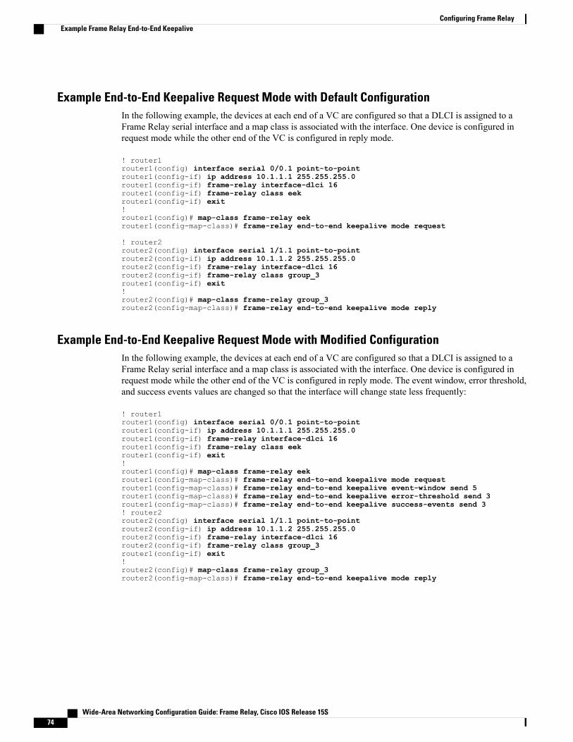
Example End-to-End Keepalive Request Mode with Default ConfigurationIn the following example, the devices at each end of a VC are configured so that a DLCI is assigned to aFrame Relay serial interface and a map class is associated with the interface. One device is configured inrequest mode while the other end of the VC is configured in reply mode.
! router1router1(config) interface serial 0/0.1 point-to-pointrouter1(config-if) ip address 10.1.1.1 255.255.255.0router1(config-if) frame-relay interface-dlci 16router1(config-if) frame-relay class eekrouter1(config-if) exit!router1(config)# map-class frame-relay eekrouter1(config-map-class)# frame-relay end-to-end keepalive mode request
! router2router2(config) interface serial 1/1.1 point-to-pointrouter2(config-if) ip address 10.1.1.2 255.255.255.0router2(config-if) frame-relay interface-dlci 16router2(config-if) frame-relay class group_3router1(config-if) exit!router2(config)# map-class frame-relay group_3router2(config-map-class)# frame-relay end-to-end keepalive mode reply
Example End-to-End Keepalive Request Mode with Modified ConfigurationIn the following example, the devices at each end of a VC are configured so that a DLCI is assigned to aFrame Relay serial interface and a map class is associated with the interface. One device is configured inrequest mode while the other end of the VC is configured in reply mode. The event window, error threshold,and success events values are changed so that the interface will change state less frequently:
! router1router1(config) interface serial 0/0.1 point-to-pointrouter1(config-if) ip address 10.1.1.1 255.255.255.0router1(config-if) frame-relay interface-dlci 16router1(config-if) frame-relay class eekrouter1(config-if) exit!router1(config)# map-class frame-relay eekrouter1(config-map-class)# frame-relay end-to-end keepalive mode requestrouter1(config-map-class)# frame-relay end-to-end keepalive event-window send 5router1(config-map-class)# frame-relay end-to-end keepalive error-threshold send 3router1(config-map-class)# frame-relay end-to-end keepalive success-events send 3! router2router2(config) interface serial 1/1.1 point-to-pointrouter2(config-if) ip address 10.1.1.2 255.255.255.0router2(config-if) frame-relay interface-dlci 16router2(config-if) frame-relay class group_3router1(config-if) exit!router2(config)# map-class frame-relay group_3router2(config-map-class)# frame-relay end-to-end keepalive mode reply
Wide-Area Networking Configuration Guide: Frame Relay, Cisco IOS Release 15S74
Configuring Frame RelayExample Frame Relay End-to-End Keepalive
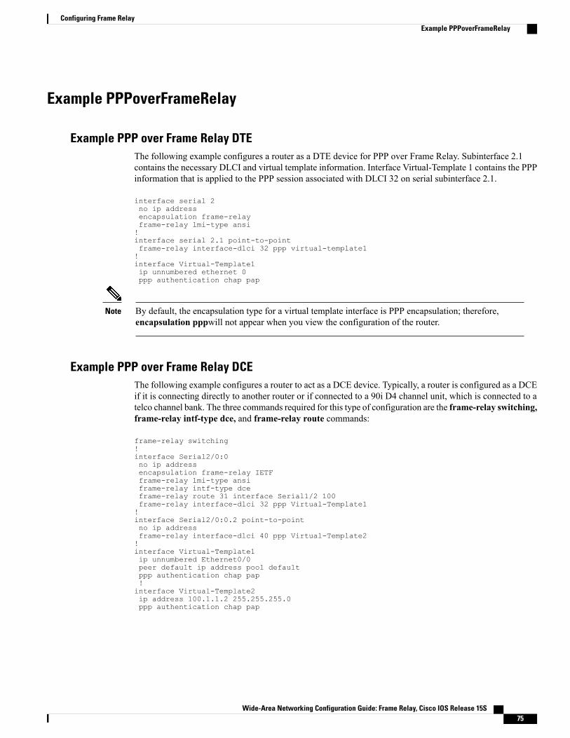
Example PPPoverFrameRelay
Example PPP over Frame Relay DTEThe following example configures a router as a DTE device for PPP over Frame Relay. Subinterface 2.1contains the necessary DLCI and virtual template information. Interface Virtual-Template 1 contains the PPPinformation that is applied to the PPP session associated with DLCI 32 on serial subinterface 2.1.
interface serial 2no ip addressencapsulation frame-relayframe-relay lmi-type ansi!interface serial 2.1 point-to-pointframe-relay interface-dlci 32 ppp virtual-template1!interface Virtual-Template1ip unnumbered ethernet 0ppp authentication chap pap
By default, the encapsulation type for a virtual template interface is PPP encapsulation; therefore,encapsulation pppwill not appear when you view the configuration of the router.
Note
Example PPP over Frame Relay DCEThe following example configures a router to act as a DCE device. Typically, a router is configured as a DCEif it is connecting directly to another router or if connected to a 90i D4 channel unit, which is connected to atelco channel bank. The three commands required for this type of configuration are the frame-relay switching,frame-relay intf-type dce, and frame-relay route commands:
frame-relay switching!interface Serial2/0:0no ip addressencapsulation frame-relay IETFframe-relay lmi-type ansiframe-relay intf-type dceframe-relay route 31 interface Serial1/2 100frame-relay interface-dlci 32 ppp Virtual-Template1!interface Serial2/0:0.2 point-to-pointno ip addressframe-relay interface-dlci 40 ppp Virtual-Template2!interface Virtual-Template1ip unnumbered Ethernet0/0peer default ip address pool defaultppp authentication chap pap!interface Virtual-Template2ip address 100.1.1.2 255.255.255.0ppp authentication chap pap
Wide-Area Networking Configuration Guide: Frame Relay, Cisco IOS Release 15S 75
Configuring Frame RelayExample PPPoverFrameRelay

By default, the encapsulation type for a virtual template interface is PPP encapsulation; therefore,encapsulation pppwill not appear when you view the configuration of the router.
Note
Example Frame Relay Fragmentation Configuration
Example FRF.12 FragmentationThe following example shows the configuration of pure end-to-end FRF.12 fragmentation and weighted fairqueueing in the map class called "frag". The fragment payload size is set to 40 bytes. The "frag" map class isassociated with DLCI 100 on serial interface 1.router(config)#interface serial 1
router(config-if)# frame-relay interface-dlci 100router(config-fr-dlci)# class fragrouter(config-fr-dlci)# exitrouter(config)# map-class frame-relay fragrouter(config-map-class)# frame-relay fragment 40
Example Frame Relay Fragmentation with Hardware CompressionIn the following example, FRF.12 fragmentation and FRF.9 hardware compression are configured onmultipointinterface 3/1 and point-to-point interface 3/1.1:
interface serial3/1ip address 10.1.0.1 255.255.255.0encapsulation frame-relayframe-relay traffic-shapingframe-relay class fragframe-relay map ip 10.1.0.2 110 broadcast ietf payload-compression frf9 stac!interface serial3/1.1 point-to-pointip address 10.2.0.1 255.255.255.0frame-relay interface-dlci 120 ietfframe-relay payload-compression frf9 stac!map-class frame-relay fragframe-relay cir 64000frame-relay bc 640frame-relay fragment 100
Example Payload Compression Configuration
Shut down the interface or subinterface prior to adding or changing compression techniques. Althoughshutdown is not required, shutting down the interface ensures that it is reset for the new data structures.
Note
Wide-Area Networking Configuration Guide: Frame Relay, Cisco IOS Release 15S76
Configuring Frame RelayExample Frame Relay Fragmentation Configuration

Example FRF.9 Compression for Subinterfaces Using the frame-relaymap CommandThe following example shows a subinterface being configured for FRF.9 compression using the frame-relaymap command:
interface serial2/0/1ip address 172.16.1.4 255.255.255.0no ip route-cacheencapsulation frame-relay IETFno keepaliveframe-relay map ip 172.16.1.1 105 IETF payload-compression FRF9 stac
Example FRF.9 Compression for SubinterfacesThe following example shows a subinterface being configured for FRF.9 compression:
interface serial2/0/0no ip addressno ip route-cacheencapsulation frame-relayip route-cache distributedno keepalive!interface serial2/0/0.500 point-to-pointip address 172.16.1.4 255.255.255.0no cdp enableframe-relay interface-dlci 500 IETFframe-relay payload-compression FRF9 stac
Example Data-Stream Hardware Compression with TCP IP Header Compression on aPoint-to-Point Subinterface
The following example shows the configuration of data-stream hardware compression and TCP headercompression on point-to-point interface 1/0.1:
interface serial1/0encapsulation frame-relayframe-relay traffic-shaping!interface serial1/0.1 point-to-pointip address 10.0.0.1 255.0.0.0frame-relay interface-dlci 100frame-relay payload-compression data-stream stacframe-relay ip tcp header-compression
Example Data-Stream Hardware Compression with TCP IP Header Compression on a MultipointSubinterface
The following example shows the configuration of data-stream hardware compression and TCP headercompression on multipoint interface 3/1:
interface serial3/1ip address 10.1.0.1 255.255.255.0encapsulation frame-relayframe-relay traffic-shapingframe-relay map ip 10.1.0.2 110 broadcast cisco payload-compression data-stream stacframe-relay ip tcp header-compression
Wide-Area Networking Configuration Guide: Frame Relay, Cisco IOS Release 15S 77
Configuring Frame RelayExample Payload Compression Configuration

Example Data-Stream Hardware Compression with RTP Header Compression and Frame RelayFragmentation
The following example shows the configuration of data-stream hardware compression, RTP header compression,and FRF.12 fragmentation on point-to-point interface 1/0.1:
interface serial1/0encapsulation frame-relayframe-relay traffic-shaping!interface serial1/0.1 point-to-pointip address 10.0.0.1 255.0.0.0frame-relay interface-dlci 100frame-relay class fragframe-relay payload-compression data-stream stacframe-relay ip rtp header-compression!map-class frame-relay fragframe-relay cir 64000frame-relay bc 640frame-relay be 0frame-relay fragment 100frame-relay ip rtp priority 16000 16000 20
Example TCP IP Header Compression
Example IP Map with Inherited TCP IP Header Compression
Shut down the interface or subinterface prior to adding or changing compression techniques. Althoughshutdown is not required, shutting down the interface ensures that it is reset for the new data structures.
Note
The following example shows an interface configured for TCP/IP header compression and an IP map thatinherits the compression characteristics. Note that the Frame Relay IP map is not explicitly configured forheader compression.interface serial 1encapsulation frame-relayip address 131.108.177.178 255.255.255.0frame-relay map ip 131.108.177.177 177 broadcastframe-relay ip tcp header-compression passiveUse of the show frame-relay map command will display the resulting compression and encapsulationcharacteristics; the IP map has inherited passive TCP/IP header compression:Router> show frame-relay mapSerial 1 (administratively down): ip 131.108.177.177
dlci 177 (0xB1,0x2C10), static,broadcast,CISCOTCP/IP Header Compression (inherited), passive (inherited)
This example also applies to dynamic mappings achieved with the use of Inverse ARP on point-to-pointsubinterfaces where no Frame Relay maps are configured.
Wide-Area Networking Configuration Guide: Frame Relay, Cisco IOS Release 15S78
Configuring Frame RelayExample TCP IP Header Compression

Example Using an IP Map to Override TCP IP Header CompressionThe following example shows the use of a Frame Relay IPmap to override the compression set on the interface:interface serial 1encapsulation frame-relayip address 131.108.177.178 255.255.255.0frame-relay map ip 131.108.177.177 177 broadcast nocompressframe-relay ip tcp header-compression passiveUse of the show frame-relay map command will display the resulting compression and encapsulationcharacteristics; the IP map has not inherited TCP header compression:Router> show frame-relay mapSerial 1 (administratively down): ip 131.108.177.177
dlci 177 (0xB1,0x2C10), static,broadcast,CISCO
Example Disabling Inherited TCP IP Header CompressionIn this example, following is the initial configuration:interface serial 1encapsulation frame-relayip address 131.108.177.179 255.255.255.0frame-relay ip tcp header-compression passiveframe-relay map ip 131.108.177.177 177 broadcastframe-relay map ip 131.108.177.178 178 broadcast tcp header-compressionEnter the following commands to enable inherited TCP/IP header compression:serial interface 1no frame-relay ip tcp header-compressionUse of the show frame-relay map command will display the resulting compression and encapsulationcharacteristics:Router> show frame-relay mapSerial 1 (administratively down): ip 131.108.177.177 177
dlci 177(0xB1, 0x2C10), static,broadcastCISCO
Serial 1 (administratively down): ip 131.108.177.178 178dlci 178(0xB2,0x2C20), staticbroadcastCISCOTCP/IP Header Compression (enabled)
As a result, header compression is disabled for the first map (with DLCI 177), which inherited its headercompression characteristics from the interface. However, header compression is not disabled for the secondmap (DLCI 178), which is explicitly configured for header compression.
Example Disabling Explicit TCP IP Header CompressionIn this example, the initial configuration is the same as in the preceding example, but you must enter thefollowing set of commands to enable explicit TCP/IP header compression:serial interface 1no frame-relay ip tcp header-compressionframe-relay map ip 131.108.177.178 178 nocompressUse of the show frame-relay map command will display the resulting compression and encapsulationcharacteristics:Router> show frame-relay mapSerial 1 (administratively down): ip 131.108.177.177 177
dlci 177(0xB1,0x2C10), static,broadcast
Wide-Area Networking Configuration Guide: Frame Relay, Cisco IOS Release 15S 79
Configuring Frame RelayExample TCP IP Header Compression

CISCOSerial 1 (administratively down): ip 131.108.177.178 178
dlci 178(0xB2,0x2C20), staticbroadcastCISCO
The result of the commands is to disable header compression for the first map (with DLCI 177), which inheritedits header compression characteristics from the interface, and also explicitly to disable header compressionfor the second map (with DLCI 178), which was explicitly configured for header compression.
Additional ReferencesRelated Documents
Document TitleRelated Topic
Cisco IOS XE Wide-Area Networking ConfigurationGuide
Cisco IOSWide-AreaNetworking configuration tasks
Cisco IOS Wide-Area Networking CommandReference
Wide-Area networking commands
• Configuring Legacy DDR Spokes
• Configuring Legacy DDR Hubs
Sending DDR traffic over Frame Relay
Loading and Maintaining System ImagesInstalling software on a new router or access serverby downloading from a central server over aninterface that supports Frame Relay
Overview - Basic Configuration of a CiscoNetworking Device
Using AutoInstall over Frame Relay
Configuring Transparent BridgingConfiguring transparent bridging between devicesover a Frame Relay network
Configuring Source-Route BridgingConfiguring source-route bridging between SNAdevices over a Frame Relay network
Configuring Serial Tunnel and Block Serial TunnelConfiguring serial tunnel (STUN) and block serialtunnel encapsulation between devices over a FrameRelay network
Configuring SNA Frame Relay Access SupportConfiguring access between SNA devices over aFrame Relay network
Configuring Voice over Frame RelayConfiguring Voice over Frame Relay Using FRF.11and FRF.12
Wide-Area Networking Configuration Guide: Frame Relay, Cisco IOS Release 15S80
Configuring Frame RelayAdditional References

Document TitleRelated Topic
Cisco IOS Quality of Service Solutions ConfigurationGuide
Configuring low latency queueing, PVC interfacepriority queueing, and link fragmentation andinterleaving using multilink PPP for Frame Relay
Standards
TitleStandard
--None
MIBs
MIBs LinkMIB
To locate and downloadMIBs for selected platforms,Cisco IOSXE software releases, and feature sets, useCisco MIB Locator found at the following URL:
http://www.cisco.com/go/mibs
None
RFCs
TitleRFC
--None
Technical Assistance
LinkDescription
http://www.cisco.com/techsupportThe Cisco Support website provides extensive onlineresources, including documentation and tools fortroubleshooting and resolving technical issues withCisco products and technologies.
To receive security and technical information aboutyour products, you can subscribe to various services,such as the Product Alert Tool (accessed from FieldNotices), the Cisco Technical Services Newsletter,and Really Simple Syndication (RSS) Feeds.
Access to most tools on the Cisco Support websiterequires a Cisco.com user ID and password.
Wide-Area Networking Configuration Guide: Frame Relay, Cisco IOS Release 15S 81
Configuring Frame RelayAdditional References

Wide-Area Networking Configuration Guide: Frame Relay, Cisco IOS Release 15S82
Configuring Frame RelayAdditional References