configuring ip routing - cisco - global home page cisco security appliance command line...
TRANSCRIPT
Cisco SecOL-10088-02
C H A P T E R 9
Configuring IP RoutingThis chapter describes how to configure IP routing on the security appliance. This chapter includes the following sections:
• How Routing Behaves Within the ASA Security Appliance, page 9-1
• Configuring Static and Default Routes, page 9-2
• Defining Route Maps, page 9-7
• Configuring OSPF, page 9-8
• Configuring RIP, page 9-20
• The Routing Table, page 9-24
• Dynamic Routing and Failover, page 9-26
How Routing Behaves Within the ASA Security ApplianceThe ASA security appliance uses both routing table and XLATE tables for routing decisions. To handle destination IP translated traffic, that is, untranslated traffic, ASA searches for existing XLATE, or static translation to select the egress interface. The selection process is as follows:
Egress Interface Selection Process
1. If destination IP translating XLATE already exists, the egress interface for the packet is determined from the XLATE table, but not from the routing table.
2. If destination IP translating XLATE does not exist, but a matching static translation exists, then the egress interface is determined from the static route and an XLATE is created, and the routing table is not used.
3. If destination IP translating XLATE does not exist and no matching static translation exists, the packet is not destination IP translated. The security appliance processes this packet by looking up the route to select egress interface, then source IP translation is performed (if necessary).
For regular dynamic outbound NAT, initial outgoing packets are routed using the route table and then creating the XLATE. Incoming return packets are forwarded using existing XLATE only. For static NAT, destination translated incoming packets are always forwarded using existing XLATE or static translation rules.
9-1urity Appliance Command Line Configuration Guide
Chapter 9 Configuring IP Routing Configuring Static and Default Routes
Next Hop Selection Process
After selecting egress interface using any method described above, an additional route lookup is performed to find out suitable next hop(s) that belong to previously selected egress interface. If there are no routes in routing table that explicitly belong to selected interface, the packet is dropped with level 6 error message 110001 "no route to host", even if there is another route for a given destination network that belongs to different egress interface. If the route that belongs to selected egress interface is found, the packet is forwarded to corresponding next hop.
Load sharing on the security appliance is possible only for multiple next-hops available using single egress interface. Load sharing cannot share multiple egress interfaces.
If dynamic routing is in use on security appliance and route table changes after XLATE creation, for example route flap, then destination translated traffic is still forwarded using old XLATE, not via route table, until XLATE times out. It may be either forwarded to wrong interface or dropped with message 110001 "no route to host" if old route was removed from the old interface and attached to another one by routing process.
The same problem may happen when there is no route flaps on the security appliance itself, but some routing process is flapping around it, sending source translated packets that belong to the same flow through the security appliance using different interfaces. Destination translated return packets may be forwarded back using the wrong egress interface.
This issue has a high probability in same security traffic configuration, where virtually any traffic may be either source-translated or destination-translated, depending on direction of initial packet in the flow. When this issue occurs after a route flap, it can be resolved manually by using the clear xlate command, or automatically resolved by an XLATE timeout. XLATE timeout may be decreased if necessary. To ensure that this rarely happens, make sure that there is no route flaps on security appliance and around it. That is, ensure that destination translated packets that belong to the same flow are always forwarded the same way through the security appliance.
Configuring Static and Default RoutesThis section describes how to configure static and default routes on the security appliance.
Multiple context mode does not support dynamic routing, so you must use static routes for any networks to which the security appliance is not directly connected; for example, when there is a router between a network and the security appliance.
You might want to use static routes in single context mode in the following cases:
• Your networks use a different router discovery protocol from RIP or OSPF.
• Your network is small and you can easily manage static routes.
• You do not want the traffic or CPU overhead associated with routing protocols.
The simplest option is to configure a default route to send all traffic to an upstream router, relying on the router to route the traffic for you. However, in some cases the default gateway might not be able to reach the destination network, so you must also configure more specific static routes. For example, if the default gateway is outside, then the default route cannot direct traffic to any inside networks that are not directly connected to the security appliance.
In transparent firewall mode, for traffic that originates on the security appliance and is destined for a non-directly connected network, you need to configure either a default route or static routes so the security appliance knows out of which interface to send traffic. Traffic that originates on the security
9-2Cisco Security Appliance Command Line Configuration Guide
OL-10088-02
Chapter 9 Configuring IP Routing Configuring Static and Default Routes
appliance might include communications to a syslog server, Websense or N2H2 server, or AAA server. If you have servers that cannot all be reached through a single default route, then you must configure static routes.
The security appliance supports up to three equal cost routes on the same interface for load balancing.
This section includes the following topics:
• Configuring a Static Route, page 9-3
• Configuring a Default Route, page 9-4
• Configuring Static Route Tracking, page 9-5
For information about configuring IPv6 static and default routes, see the “Configuring IPv6 Default and Static Routes” section on page 12-5.
Configuring a Static RouteTo add a static route, enter the following command:
hostname(config)# route if_name dest_ip mask gateway_ip [distance]
The dest_ip and mask is the IP address for the destination network and the gateway_ip is the address of the next-hop router.The addresses you specify for the static route are the addresses that are in the packet before entering the security appliance and performing NAT.
The distance is the administrative distance for the route. The default is 1 if you do not specify a value. Administrative distance is a parameter used to compare routes among different routing protocols. The default administrative distance for static routes is 1, giving it precedence over routes discovered by dynamic routing protocols but not directly connect routes. The default administrative distance for routes discovered by OSPF is 110. If a static route has the same administrative distance as a dynamic route, the static routes take precedence. Connected routes always take precedence over static or dynamically discovered routes.
Static routes remain in the routing table even if the specified gateway becomes unavailable. If the specified gateway becomes unavailable, you need to remove the static route from the routing table manually. However, static routes are removed from the routing table if the specified interface goes down. They are reinstated when the interface comes back up.
Note If you create a static route with an administrative distance greater than the administrative distance of the routing protocol running on the security appliance, then a route to the specified destination discovered by the routing protocol takes precedence over the static route. The static route is used only if the dynamically discovered route is removed from the routing table.
The following example creates a static route that sends all traffic destined for 10.1.1.0/24 to the router (10.1.2.45) connected to the inside interface:
hostname(config)# route inside 10.1.1.0 255.255.255.0 10.1.2.45 1
You can define up to three equal cost routes to the same destination per interface. ECMP is not supported across multiple interfaces. With ECMP, the traffic is not necessarily divided evenly between the routes; traffic is distributed among the specified gateways based on an algorithm that hashes the source and destination IP addresses.
The following example shows static routes that are equal cost routes that direct traffic to three different gateways on the outside interface. The security appliance distributes the traffic among the specified gateways.
9-3Cisco Security Appliance Command Line Configuration Guide
OL-10088-02

Chapter 9 Configuring IP Routing Configuring Static and Default Routes
hostname(config)# route outside 10.10.10.0 255.255.255.0 192.168.1.1hostname(config)# route outside 10.10.10.0 255.255.255.0 192.168.1.2hostname(config)# route outside 10.10.10.0 255.255.255.0 192.168.1.3
Configuring a Default RouteA default route identifies the gateway IP address to which the security appliance sends all IP packets for which it does not have a learned or static route. A default route is simply a static route with 0.0.0.0/0 as the destination IP address. Routes that identify a specific destination take precedence over the default route.
Note In ASA software Versions 7.0 and later, if you have two default routes configured on different interfaces that have different metrics, the connection to the ASA firewall that is made from the higher metric interface fails, but connections to the ASA firewall from the lower metric interface succeed as expected. PIX software Version 6.3 supports connections from both the the higher and the lower metric interfaces.
You can define up to three equal cost default route entries per device. Defining more than one equal cost default route entry causes the traffic sent to the default route to be distributed among the specified gateways. When defining more than one default route, you must specify the same interface for each entry.
If you attempt to define more than three equal cost default routes, or if you attempt to define a default route with a different interface than a previously defined default route, you receive the message “ERROR: Cannot add route entry, possible conflict with existing routes.”
You can define a separate default route for tunneled traffic along with the standard default route. When you create a default route with the tunneled option, all traffic from a tunnel terminating on the security appliance that cannot be routed using learned or static routes, is sent to this route. For traffic emerging from a tunnel, this route overrides over any other configured or learned default routes.
The following restrictions apply to default routes with the tunneled option:
• Do not enable unicast RPF (ip verify reverse-path) on the egress interface of tunneled route. Enabling uRPF on the egress interface of a tunneled route causes the session to fail.
• Do not enable TCP intercept on the egress interface of the tunneled route. Doing so causes the session to fail.
• Do not use the VoIP inspection engines (CTIQBE, H.323, GTP, MGCP, RTSP, SIP, SKINNY), the DNS inspect engine, or the DCE RPC inspection engine with tunneled routes. These inspection engines ignore the tunneled route.
You cannot define more than one default route with the tunneled option; ECMP for tunneled traffic is not supported.
To define the default route, enter the following command:
hostname(config)# route if_name 0.0.0.0 0.0.0.0 gateway_ip [distance | tunneled]
Tip You can enter 0 0 instead of 0.0.0.0 0.0.0.0 for the destination network address and mask, for example: hostname(config)# route outside 0 0 192.168.1 1
9-4Cisco Security Appliance Command Line Configuration Guide
OL-10088-02
Chapter 9 Configuring IP Routing Configuring Static and Default Routes
The following example shows a security appliance configured with three equal cost default routes and a default route for tunneled traffic. Unencrypted traffic received by the security appliance for which there is no static or learned route is distributed among the gateways with the IP addresses 192.168.2.1, 192.168.2.2, 192.168.2.3. Encrypted traffic receive by the security appliance for which there is no static or learned route is passed to the gateway with the IP address 192.168.2.4.
hostname(config)# route outside 0 0 192.168.2.1hostname(config)# route outside 0 0 192.168.2.2hostname(config)# route outside 0 0 192.168.2.3hostname(config)# route outside 0 0 192.168.2.4 tunneled
Configuring Static Route TrackingOne of the problems with static routes is that there is no inherent mechanism for determining if the route is up or down. They remain in the routing table even if the next hop gateway becomes unavailable. Static routes are only removed from the routing table if the associated interface on the security appliance goes down.
The static route tracking feature provides a method for tracking the availability of a static route and installing a backup route if the primary route should fail. This allows you to, for example, define a default route to an ISP gateway and a backup default route to a secondary ISP in case the primary ISP becomes unavailable.
The security appliance does this by associating a static route with a monitoring target that you define. It monitors the target using ICMP echo requests. If an echo reply is not received within a specified time period, the object is considered down and the associated route is removed from the routing table. A previously configured backup route is used in place of the removed route.
When selecting a monitoring target, you need to make sure it can respond to ICMP echo requests. The target can be any network object that you choose, but you should consider using:
• the ISP gateway (for dual ISP support) address
• the next hop gateway address (if you are concerned about the availability of the gateway)
• a server on the target network, such as a AAA server, that the security appliance needs to communicate with
• a persistent network object on the destination network (a desktop or notebook computer that may be shut down at night is not a good choice)
You can configure static route tracking for statically defined routes or default routes obtained through DHCP or PPPoE. You can only enable PPPoE clients on multiple interface with route tracking.
To configure static route tracking, perform the following steps:
Step 1 Configure the tracked object monitoring parameters:
a. Define the monitoring process:
hostname(config)# sla monitor sla_id
If you are configuring a new monitoring process, you are taken to SLA monitor configuration mode. If you are changing the monitoring parameters for an unscheduled monitoring process that already has a type defined, you are taken directly to the SLA protocol configuration mode.
b. Specify the monitoring protocol. If you are changing the monitoring parameters for an unscheduled monitoring process that already has a type defined, you are taken directly to SLA protocol configuration mode and cannot change this setting.
9-5Cisco Security Appliance Command Line Configuration Guide
OL-10088-02
Chapter 9 Configuring IP Routing Configuring Static and Default Routes
hostname(config-sla-monitor)# type echo protocol ipIcmpEcho target_ip interface if_name
The target_ip is the IP address of the network object whose availability the tracking process monitors. While this object is available, the tracking process route is installed in the routing table. When this object becomes unavailable, the tracking process removed the route and the backup route is used in its place.
c. Schedule the monitoring process:
hostname(config)# sla monitor schedule sla_id [life {forever | seconds}] [start-time {hh:mm[:ss] [month day | day month] | pending | now | after hh:mm:ss}] [ageout seconds] [recurring]
Typically, you will use sla monitor schedule sla_id life forever start-time now for the monitoring schedule, and allow the monitoring configuration determine how often the testing occurs. However, you can schedule this monitoring process to begin in the future and to only occur at specified times.
Step 2 Associate a tracked static route with the SLA monitoring process by entering the following command:
hostname(config)# track track_id rtr sla_id reachability
The track_id is a tracking number you assign with this command. The sla_id is the ID number of the SLA process you defined in Step 1.
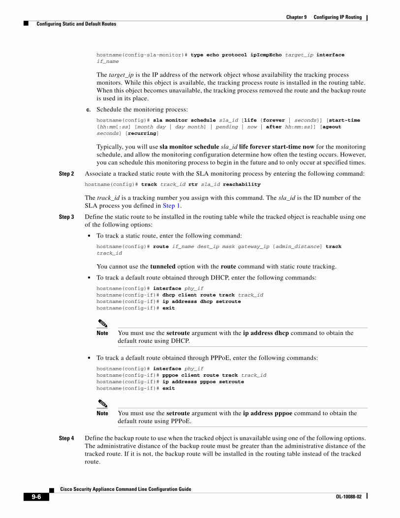
Step 3 Define the static route to be installed in the routing table while the tracked object is reachable using one of the following options:
• To track a static route, enter the following command:
hostname(config)# route if_name dest_ip mask gateway_ip [admin_distance] track track_id
You cannot use the tunneled option with the route command with static route tracking.
• To track a default route obtained through DHCP, enter the following commands:
hostname(config)# interface phy_ifhostname(config-if)# dhcp client route track track_idhostname(config-if)# ip addresss dhcp setroutehostname(config-if)# exit
Note You must use the setroute argument with the ip address dhcp command to obtain the default route using DHCP.
• To track a default route obtained through PPPoE, enter the following commands:
hostname(config)# interface phy_ifhostname(config-if)# pppoe client route track track_idhostname(config-if)# ip addresss pppoe setroutehostname(config-if)# exit
Note You must use the setroute argument with the ip address pppoe command to obtain the default route using PPPoE.
Step 4 Define the backup route to use when the tracked object is unavailable using one of the following options. The administrative distance of the backup route must be greater than the administrative distance of the tracked route. If it is not, the backup route will be installed in the routing table instead of the tracked route.
9-6Cisco Security Appliance Command Line Configuration Guide
OL-10088-02
Chapter 9 Configuring IP Routing Defining Route Maps
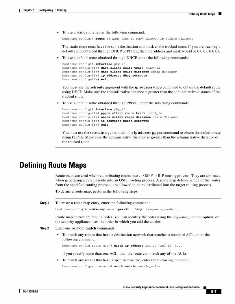
• To use a static route, enter the following command:
hostname(config)# route if_name dest_ip mask gateway_ip [admin_distance]
The static route must have the same destination and mask as the tracked route. If you are tracking a default route obtained through DHCP or PPPoE, then the address and mask would be 0.0.0.0 0.0.0.0.
• To use a default route obtained through DHCP, enter the following commands:
hostname(config)# interface phy_ifhostname(config-if)# dhcp client route track track_idhostname(config-if)# dhcp client route distance admin_distancehostname(config-if)# ip addresss dhcp setroutehostname(config-if)# exit
You must use the setroute argument with the ip address dhcp command to obtain the default route using DHCP. Make sure the administrative distance is greater than the administrative distance of the tracked route.
• To use a default route obtained through PPPoE, enter the following commands:
hostname(config)# interface phy_ifhostname(config-if)# pppoe client route track track_idhostname(config-if)# pppoe client route distance admin_distancehostname(config-if)# ip addresss pppoe setroutehostname(config-if)# exit
You must use the setroute argument with the ip address pppoe command to obtain the default route using PPPoE. Make sure the administrative distance is greater than the administrative distance of the tracked route.
Defining Route MapsRoute maps are used when redistributing routes into an OSPF or RIP routing process. They are also used when generating a default route into an OSPF routing process. A route map defines which of the routes from the specified routing protocol are allowed to be redistributed into the target routing process.
To define a route map, perform the following steps:
Step 1 To create a route map entry, enter the following command:
hostname(config)# route-map name {permit | deny} [sequence_number]
Route map entries are read in order. You can identify the order using the sequence_number option, or the security appliance uses the order in which you add the entries.
Step 2 Enter one or more match commands:
• To match any routes that have a destination network that matches a standard ACL, enter the following command:
hostname(config-route-map)# match ip address acl_id [acl_id] [...]
If you specify more than one ACL, then the route can match any of the ACLs.
• To match any routes that have a specified metric, enter the following command:
hostname(config-route-map)# match metric metric_value
9-7Cisco Security Appliance Command Line Configuration Guide
OL-10088-02
Chapter 9 Configuring IP Routing Configuring OSPF
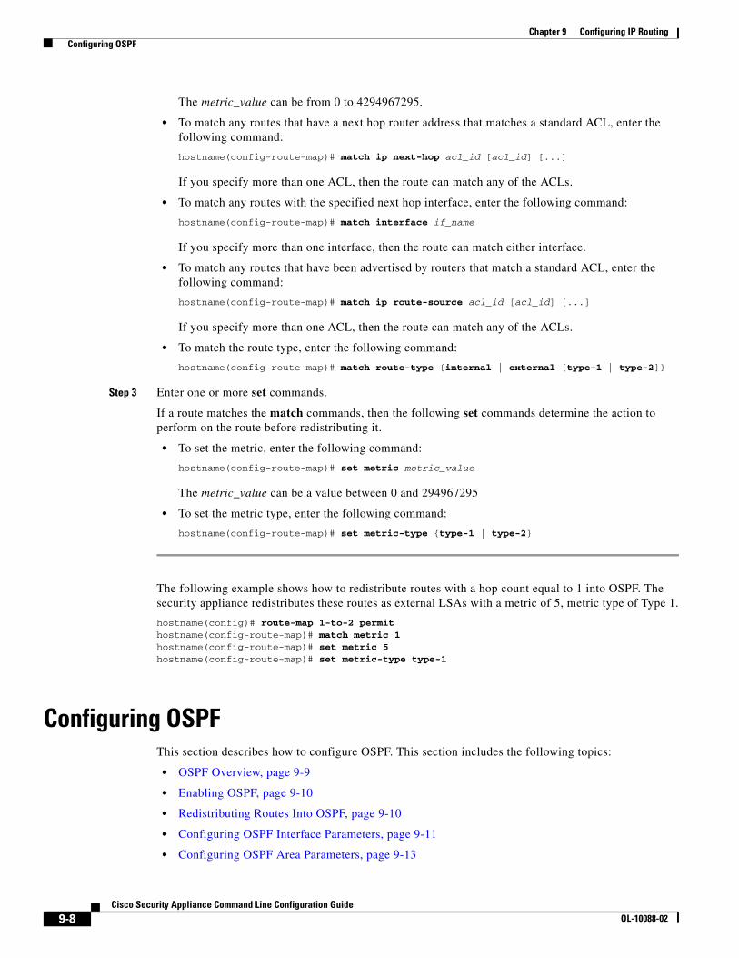
The metric_value can be from 0 to 4294967295.
• To match any routes that have a next hop router address that matches a standard ACL, enter the following command:
hostname(config-route-map)# match ip next-hop acl_id [acl_id] [...]
If you specify more than one ACL, then the route can match any of the ACLs.
• To match any routes with the specified next hop interface, enter the following command:
hostname(config-route-map)# match interface if_name
If you specify more than one interface, then the route can match either interface.
• To match any routes that have been advertised by routers that match a standard ACL, enter the following command:
hostname(config-route-map)# match ip route-source acl_id [acl_id] [...]
If you specify more than one ACL, then the route can match any of the ACLs.
• To match the route type, enter the following command:
hostname(config-route-map)# match route-type {internal | external [type-1 | type-2]}
Step 3 Enter one or more set commands.
If a route matches the match commands, then the following set commands determine the action to perform on the route before redistributing it.
• To set the metric, enter the following command:
hostname(config-route-map)# set metric metric_value
The metric_value can be a value between 0 and 294967295
• To set the metric type, enter the following command:
hostname(config-route-map)# set metric-type {type-1 | type-2}
The following example shows how to redistribute routes with a hop count equal to 1 into OSPF. The security appliance redistributes these routes as external LSAs with a metric of 5, metric type of Type 1.
hostname(config)# route-map 1-to-2 permithostname(config-route-map)# match metric 1hostname(config-route-map)# set metric 5hostname(config-route-map)# set metric-type type-1
Configuring OSPFThis section describes how to configure OSPF. This section includes the following topics:
• OSPF Overview, page 9-9
• Enabling OSPF, page 9-10
• Redistributing Routes Into OSPF, page 9-10
• Configuring OSPF Interface Parameters, page 9-11
• Configuring OSPF Area Parameters, page 9-13
9-8Cisco Security Appliance Command Line Configuration Guide
OL-10088-02
Chapter 9 Configuring IP Routing Configuring OSPF
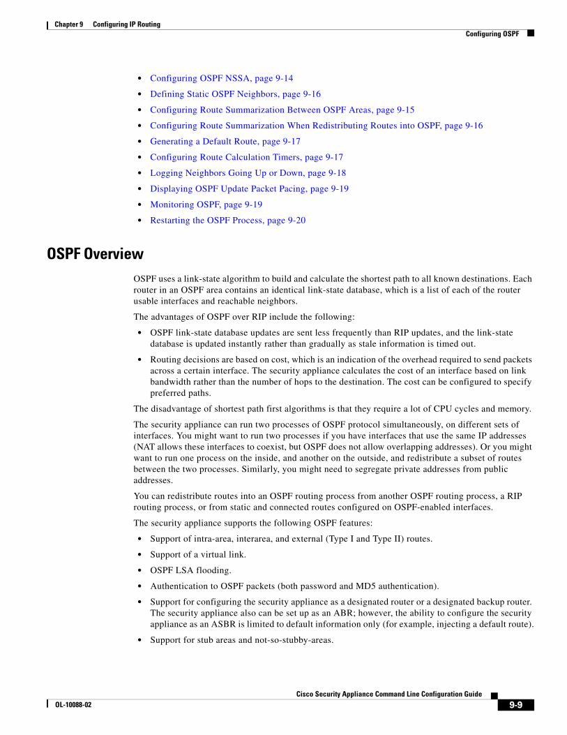
• Configuring OSPF NSSA, page 9-14
• Defining Static OSPF Neighbors, page 9-16
• Configuring Route Summarization Between OSPF Areas, page 9-15
• Configuring Route Summarization When Redistributing Routes into OSPF, page 9-16
• Generating a Default Route, page 9-17
• Configuring Route Calculation Timers, page 9-17
• Logging Neighbors Going Up or Down, page 9-18
• Displaying OSPF Update Packet Pacing, page 9-19
• Monitoring OSPF, page 9-19
• Restarting the OSPF Process, page 9-20
OSPF OverviewOSPF uses a link-state algorithm to build and calculate the shortest path to all known destinations. Each router in an OSPF area contains an identical link-state database, which is a list of each of the router usable interfaces and reachable neighbors.
The advantages of OSPF over RIP include the following:
• OSPF link-state database updates are sent less frequently than RIP updates, and the link-state database is updated instantly rather than gradually as stale information is timed out.
• Routing decisions are based on cost, which is an indication of the overhead required to send packets across a certain interface. The security appliance calculates the cost of an interface based on link bandwidth rather than the number of hops to the destination. The cost can be configured to specify preferred paths.
The disadvantage of shortest path first algorithms is that they require a lot of CPU cycles and memory.
The security appliance can run two processes of OSPF protocol simultaneously, on different sets of interfaces. You might want to run two processes if you have interfaces that use the same IP addresses (NAT allows these interfaces to coexist, but OSPF does not allow overlapping addresses). Or you might want to run one process on the inside, and another on the outside, and redistribute a subset of routes between the two processes. Similarly, you might need to segregate private addresses from public addresses.
You can redistribute routes into an OSPF routing process from another OSPF routing process, a RIP routing process, or from static and connected routes configured on OSPF-enabled interfaces.
The security appliance supports the following OSPF features:
• Support of intra-area, interarea, and external (Type I and Type II) routes.
• Support of a virtual link.
• OSPF LSA flooding.
• Authentication to OSPF packets (both password and MD5 authentication).
• Support for configuring the security appliance as a designated router or a designated backup router. The security appliance also can be set up as an ABR; however, the ability to configure the security appliance as an ASBR is limited to default information only (for example, injecting a default route).
• Support for stub areas and not-so-stubby-areas.
9-9Cisco Security Appliance Command Line Configuration Guide
OL-10088-02
Chapter 9 Configuring IP Routing Configuring OSPF
• Area boundary router type-3 LSA filtering.
• Advertisement of static and global address translations.
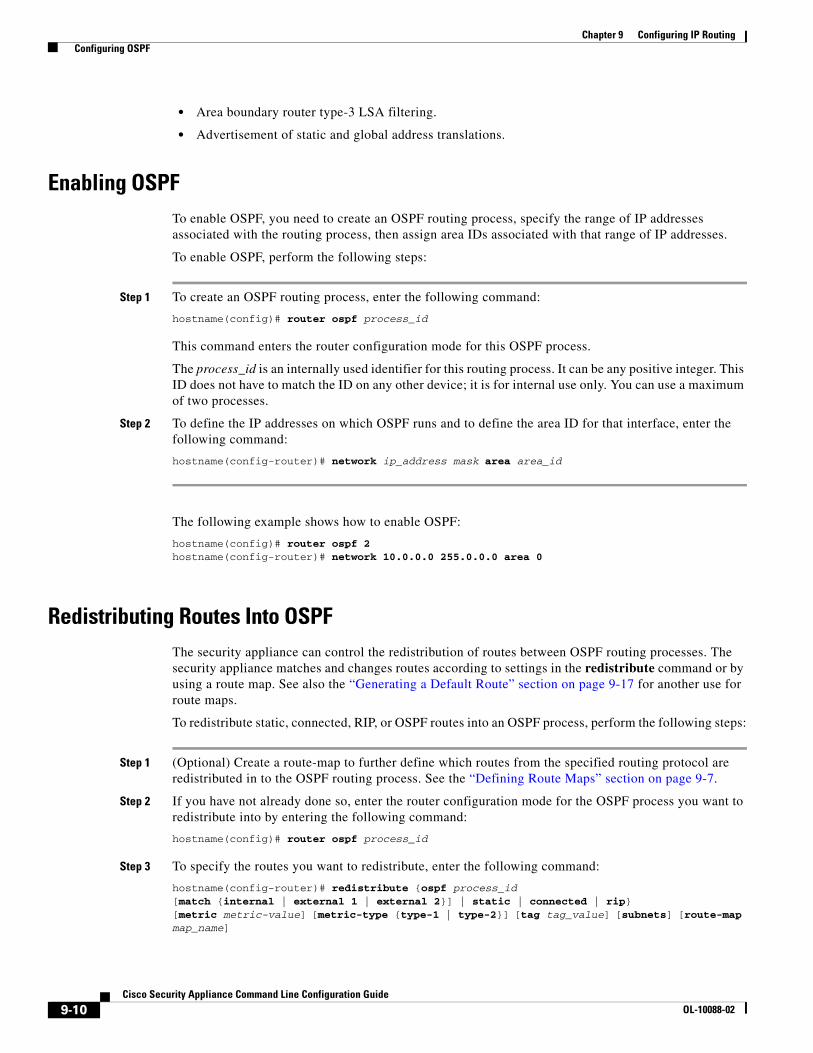
Enabling OSPFTo enable OSPF, you need to create an OSPF routing process, specify the range of IP addresses associated with the routing process, then assign area IDs associated with that range of IP addresses.
To enable OSPF, perform the following steps:
Step 1 To create an OSPF routing process, enter the following command:
hostname(config)# router ospf process_id
This command enters the router configuration mode for this OSPF process.
The process_id is an internally used identifier for this routing process. It can be any positive integer. This ID does not have to match the ID on any other device; it is for internal use only. You can use a maximum of two processes.
Step 2 To define the IP addresses on which OSPF runs and to define the area ID for that interface, enter the following command:
hostname(config-router)# network ip_address mask area area_id
The following example shows how to enable OSPF:
hostname(config)# router ospf 2hostname(config-router)# network 10.0.0.0 255.0.0.0 area 0
Redistributing Routes Into OSPFThe security appliance can control the redistribution of routes between OSPF routing processes. The security appliance matches and changes routes according to settings in the redistribute command or by using a route map. See also the “Generating a Default Route” section on page 9-17 for another use for route maps.
To redistribute static, connected, RIP, or OSPF routes into an OSPF process, perform the following steps:
Step 1 (Optional) Create a route-map to further define which routes from the specified routing protocol are redistributed in to the OSPF routing process. See the “Defining Route Maps” section on page 9-7.
Step 2 If you have not already done so, enter the router configuration mode for the OSPF process you want to redistribute into by entering the following command:
hostname(config)# router ospf process_id
Step 3 To specify the routes you want to redistribute, enter the following command:
hostname(config-router)# redistribute {ospf process_id [match {internal | external 1 | external 2}] | static | connected | rip} [metric metric-value] [metric-type {type-1 | type-2}] [tag tag_value] [subnets] [route-map map_name]
9-10Cisco Security Appliance Command Line Configuration Guide
OL-10088-02
Chapter 9 Configuring IP Routing Configuring OSPF
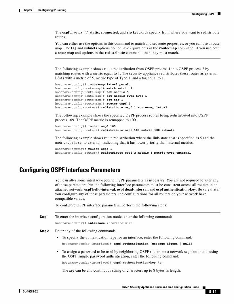
The ospf process_id, static, connected, and rip keywords specify from where you want to redistribute routes.
You can either use the options in this command to match and set route properties, or you can use a route map. The tag and subnets options do not have equivalents in the route-map command. If you use both a route map and options in the redistribute command, then they must match.
The following example shows route redistribution from OSPF process 1 into OSPF process 2 by matching routes with a metric equal to 1. The security appliance redistributes these routes as external LSAs with a metric of 5, metric type of Type 1, and a tag equal to 1.
hostname(config)# route-map 1-to-2 permithostname(config-route-map)# match metric 1hostname(config-route-map)# set metric 5hostname(config-route-map)# set metric-type type-1hostname(config-route-map)# set tag 1hostname(config-route-map)# router ospf 2hostname(config-router)# redistribute ospf 1 route-map 1-to-2
The following example shows the specified OSPF process routes being redistributed into OSPF process 109. The OSPF metric is remapped to 100.
hostname(config)# router ospf 109hostname(config-router)# redistribute ospf 108 metric 100 subnets
The following example shows route redistribution where the link-state cost is specified as 5 and the metric type is set to external, indicating that it has lower priority than internal metrics.
hostname(config)# router ospf 1hostname(config-router)# redistribute ospf 2 metric 5 metric-type external
Configuring OSPF Interface ParametersYou can alter some interface-specific OSPF parameters as necessary. You are not required to alter any of these parameters, but the following interface parameters must be consistent across all routers in an attached network: ospf hello-interval, ospf dead-interval, and ospf authentication-key. Be sure that if you configure any of these parameters, the configurations for all routers on your network have compatible values.
To configure OSPF interface parameters, perform the following steps:
Step 1 To enter the interface configuration mode, enter the following command:
hostname(config)# interface interface_name
Step 2 Enter any of the following commands:
• To specify the authentication type for an interface, enter the following command:
hostname(config-interface)# ospf authentication [message-digest | null]
• To assign a password to be used by neighboring OSPF routers on a network segment that is using the OSPF simple password authentication, enter the following command:
hostname(config-interface)# ospf authentication-key key
The key can be any continuous string of characters up to 8 bytes in length.
9-11Cisco Security Appliance Command Line Configuration Guide
OL-10088-02
Chapter 9 Configuring IP Routing Configuring OSPF
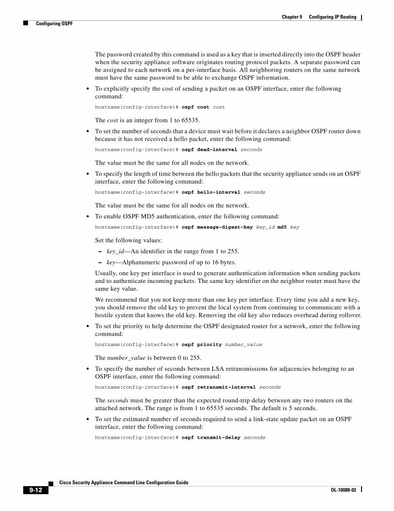
The password created by this command is used as a key that is inserted directly into the OSPF header when the security appliance software originates routing protocol packets. A separate password can be assigned to each network on a per-interface basis. All neighboring routers on the same network must have the same password to be able to exchange OSPF information.
• To explicitly specify the cost of sending a packet on an OSPF interface, enter the following command:
hostname(config-interface)# ospf cost cost
The cost is an integer from 1 to 65535.
• To set the number of seconds that a device must wait before it declares a neighbor OSPF router down because it has not received a hello packet, enter the following command:
hostname(config-interface)# ospf dead-interval seconds
The value must be the same for all nodes on the network.
• To specify the length of time between the hello packets that the security appliance sends on an OSPF interface, enter the following command:
hostname(config-interface)# ospf hello-interval seconds
The value must be the same for all nodes on the network.
• To enable OSPF MD5 authentication, enter the following command:
hostname(config-interface)# ospf message-digest-key key_id md5 key
Set the following values:
– key_id—An identifier in the range from 1 to 255.
– key—Alphanumeric password of up to 16 bytes.
Usually, one key per interface is used to generate authentication information when sending packets and to authenticate incoming packets. The same key identifier on the neighbor router must have the same key value.
We recommend that you not keep more than one key per interface. Every time you add a new key, you should remove the old key to prevent the local system from continuing to communicate with a hostile system that knows the old key. Removing the old key also reduces overhead during rollover.
• To set the priority to help determine the OSPF designated router for a network, enter the following command:
hostname(config-interface)# ospf priority number_value
The number_value is between 0 to 255.
• To specify the number of seconds between LSA retransmissions for adjacencies belonging to an OSPF interface, enter the following command:
hostname(config-interface)# ospf retransmit-interval seconds
The seconds must be greater than the expected round-trip delay between any two routers on the attached network. The range is from 1 to 65535 seconds. The default is 5 seconds.
• To set the estimated number of seconds required to send a link-state update packet on an OSPF interface, enter the following command:
hostname(config-interface)# ospf transmit-delay seconds
9-12Cisco Security Appliance Command Line Configuration Guide
OL-10088-02
Chapter 9 Configuring IP Routing Configuring OSPF
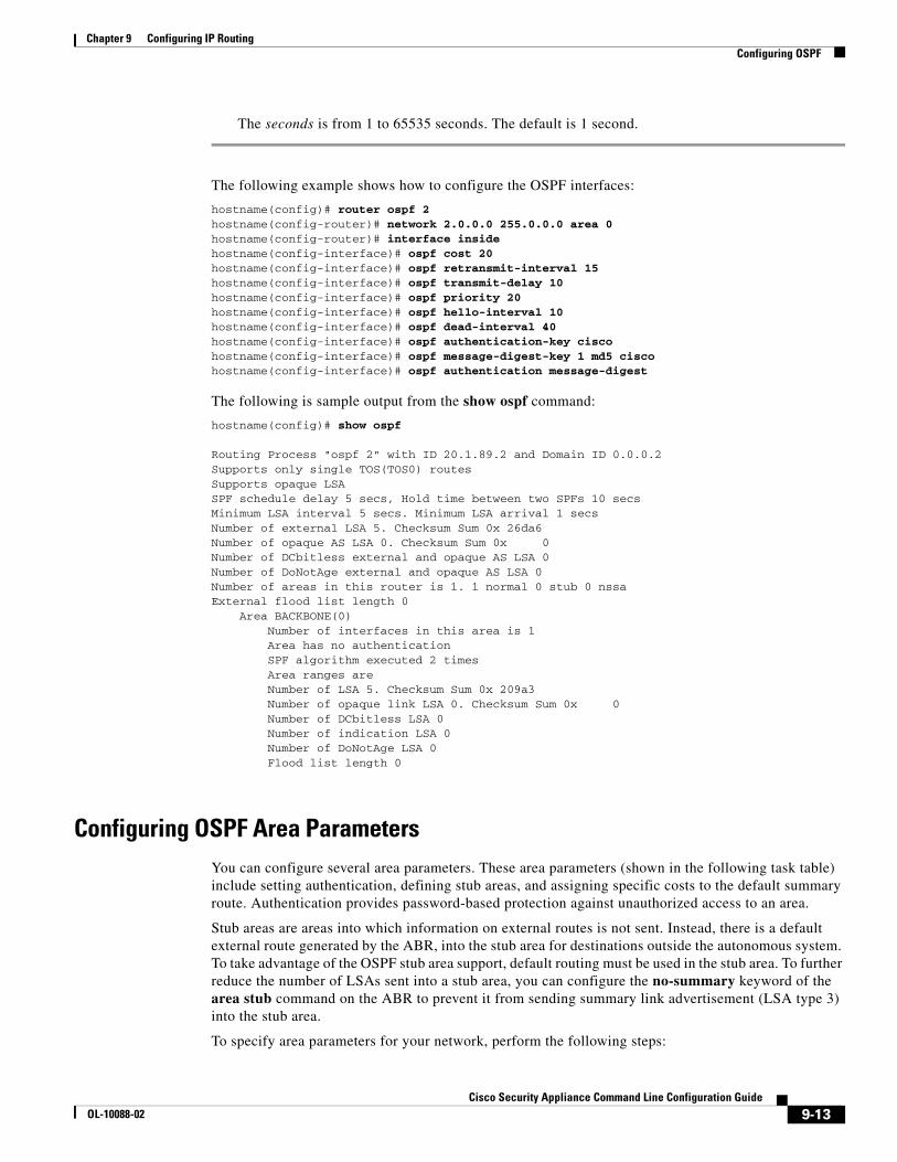
The seconds is from 1 to 65535 seconds. The default is 1 second.
The following example shows how to configure the OSPF interfaces:
hostname(config)# router ospf 2hostname(config-router)# network 2.0.0.0 255.0.0.0 area 0hostname(config-router)# interface insidehostname(config-interface)# ospf cost 20hostname(config-interface)# ospf retransmit-interval 15hostname(config-interface)# ospf transmit-delay 10hostname(config-interface)# ospf priority 20hostname(config-interface)# ospf hello-interval 10hostname(config-interface)# ospf dead-interval 40hostname(config-interface)# ospf authentication-key ciscohostname(config-interface)# ospf message-digest-key 1 md5 ciscohostname(config-interface)# ospf authentication message-digest
The following is sample output from the show ospf command:
hostname(config)# show ospf
Routing Process "ospf 2" with ID 20.1.89.2 and Domain ID 0.0.0.2Supports only single TOS(TOS0) routesSupports opaque LSASPF schedule delay 5 secs, Hold time between two SPFs 10 secsMinimum LSA interval 5 secs. Minimum LSA arrival 1 secsNumber of external LSA 5. Checksum Sum 0x 26da6Number of opaque AS LSA 0. Checksum Sum 0x 0Number of DCbitless external and opaque AS LSA 0Number of DoNotAge external and opaque AS LSA 0Number of areas in this router is 1. 1 normal 0 stub 0 nssaExternal flood list length 0 Area BACKBONE(0) Number of interfaces in this area is 1 Area has no authentication SPF algorithm executed 2 times Area ranges are Number of LSA 5. Checksum Sum 0x 209a3 Number of opaque link LSA 0. Checksum Sum 0x 0 Number of DCbitless LSA 0 Number of indication LSA 0 Number of DoNotAge LSA 0 Flood list length 0
Configuring OSPF Area ParametersYou can configure several area parameters. These area parameters (shown in the following task table) include setting authentication, defining stub areas, and assigning specific costs to the default summary route. Authentication provides password-based protection against unauthorized access to an area.
Stub areas are areas into which information on external routes is not sent. Instead, there is a default external route generated by the ABR, into the stub area for destinations outside the autonomous system. To take advantage of the OSPF stub area support, default routing must be used in the stub area. To further reduce the number of LSAs sent into a stub area, you can configure the no-summary keyword of the area stub command on the ABR to prevent it from sending summary link advertisement (LSA type 3) into the stub area.
To specify area parameters for your network, perform the following steps:
9-13Cisco Security Appliance Command Line Configuration Guide
OL-10088-02
Chapter 9 Configuring IP Routing Configuring OSPF
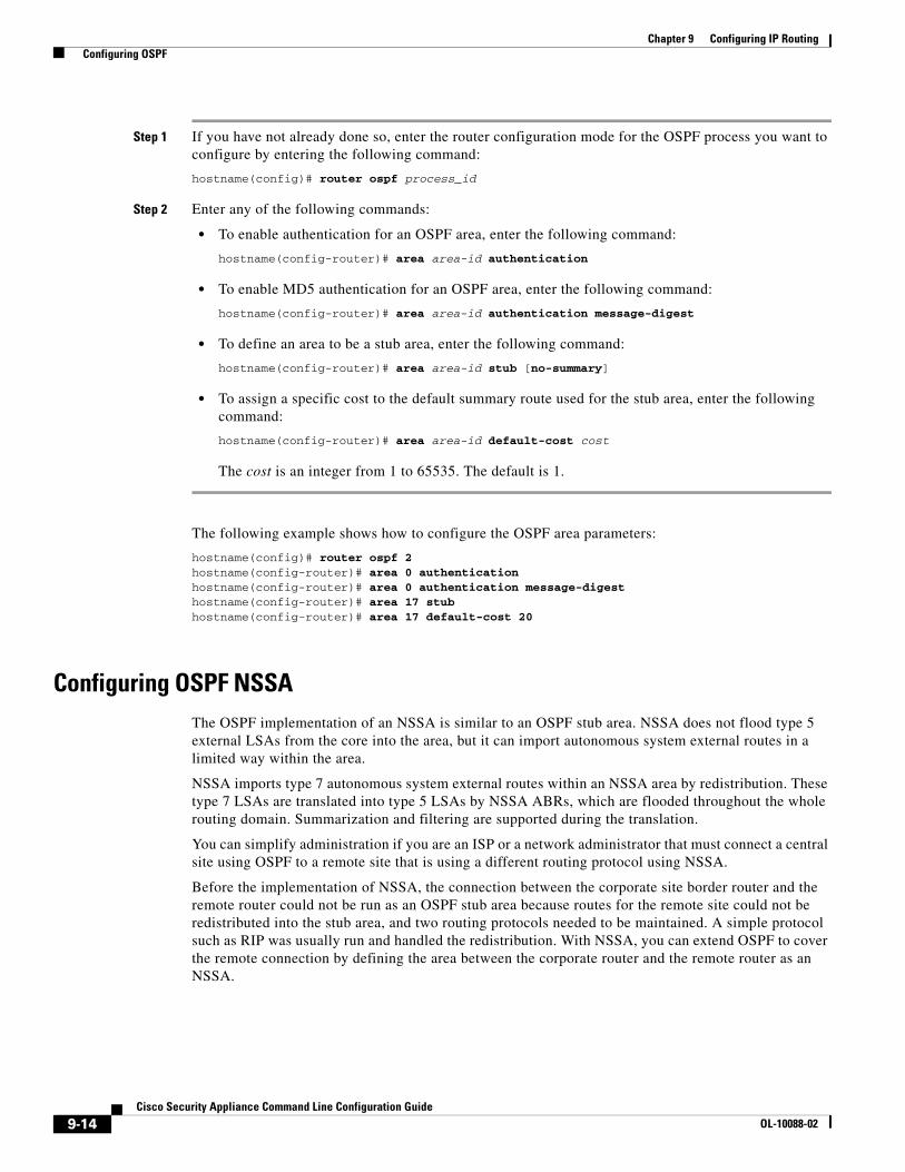
Step 1 If you have not already done so, enter the router configuration mode for the OSPF process you want to configure by entering the following command:
hostname(config)# router ospf process_id
Step 2 Enter any of the following commands:
• To enable authentication for an OSPF area, enter the following command:
hostname(config-router)# area area-id authentication
• To enable MD5 authentication for an OSPF area, enter the following command:
hostname(config-router)# area area-id authentication message-digest
• To define an area to be a stub area, enter the following command:
hostname(config-router)# area area-id stub [no-summary]
• To assign a specific cost to the default summary route used for the stub area, enter the following command:
hostname(config-router)# area area-id default-cost cost
The cost is an integer from 1 to 65535. The default is 1.
The following example shows how to configure the OSPF area parameters:
hostname(config)# router ospf 2hostname(config-router)# area 0 authenticationhostname(config-router)# area 0 authentication message-digesthostname(config-router)# area 17 stubhostname(config-router)# area 17 default-cost 20
Configuring OSPF NSSAThe OSPF implementation of an NSSA is similar to an OSPF stub area. NSSA does not flood type 5 external LSAs from the core into the area, but it can import autonomous system external routes in a limited way within the area.
NSSA imports type 7 autonomous system external routes within an NSSA area by redistribution. These type 7 LSAs are translated into type 5 LSAs by NSSA ABRs, which are flooded throughout the whole routing domain. Summarization and filtering are supported during the translation.
You can simplify administration if you are an ISP or a network administrator that must connect a central site using OSPF to a remote site that is using a different routing protocol using NSSA.
Before the implementation of NSSA, the connection between the corporate site border router and the remote router could not be run as an OSPF stub area because routes for the remote site could not be redistributed into the stub area, and two routing protocols needed to be maintained. A simple protocol such as RIP was usually run and handled the redistribution. With NSSA, you can extend OSPF to cover the remote connection by defining the area between the corporate router and the remote router as an NSSA.
9-14Cisco Security Appliance Command Line Configuration Guide
OL-10088-02

Chapter 9 Configuring IP Routing Configuring OSPF
To specify area parameters for your network as needed to configure OSPF NSSA, perform the following steps:
Step 1 If you have not already done so, enter the router configuration mode for the OSPF process you want to configure by entering the following command:
hostname(config)# router ospf process_id
Step 2 Enter any of the following commands:
• To define an NSSA area, enter the following command:
hostname(config-router)# area area-id nssa [no-redistribution] [default-information-originate]
• To summarize groups of addresses, enter the following command:
hostname(config-router)# summary address ip_address mask [not-advertise] [tag tag]
This command helps reduce the size of the routing table. Using this command for OSPF causes an OSPF ASBR to advertise one external route as an aggregate for all redistributed routes that are covered by the address.
OSPF does not support summary-address 0.0.0.0 0.0.0.0.
In the following example, the summary address 10.1.0.0 includes address 10.1.1.0, 10.1.2.0, 10.1.3.0, and so on. Only the address 10.1.0.0 is advertised in an external link-state advertisement:
hostname(config-router)# summary-address 10.1.1.0 255.255.0.0
Before you use this feature, consider these guidelines:
– You can set a type 7 default route that can be used to reach external destinations. When configured, the router generates a type 7 default into the NSSA or the NSSA area boundary router.
– Every router within the same area must agree that the area is NSSA; otherwise, the routers will not be able to communicate.
Configuring Route Summarization Between OSPF AreasRoute summarization is the consolidation of advertised addresses. This feature causes a single summary route to be advertised to other areas by an area boundary router. In OSPF, an area boundary router advertises networks in one area into another area. If the network numbers in an area are assigned in a way such that they are contiguous, you can configure the area boundary router to advertise a summary route that covers all the individual networks within the area that fall into the specified range.
To define an address range for route summarization, perform the following steps:
Step 1 If you have not already done so, enter the router configuration mode for the OSPF process you want to configure by entering the following command:
hostname(config)# router ospf process_id
9-15Cisco Security Appliance Command Line Configuration Guide
OL-10088-02
Chapter 9 Configuring IP Routing Configuring OSPF
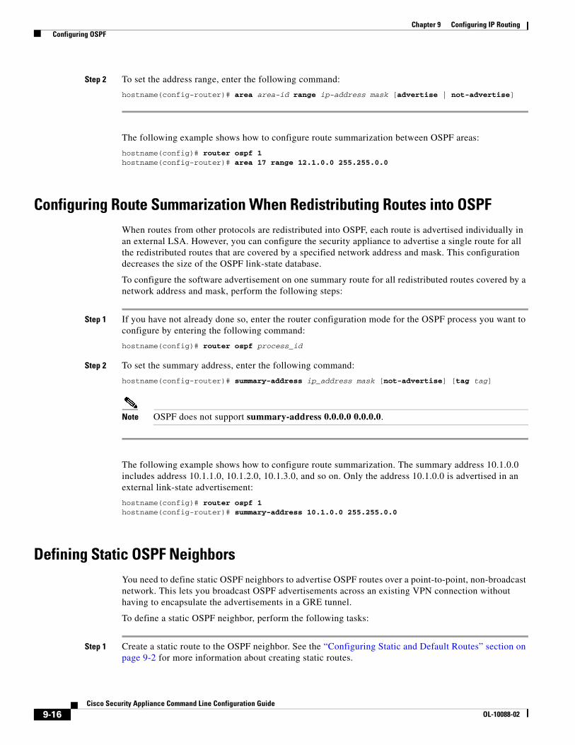
Step 2 To set the address range, enter the following command:
hostname(config-router)# area area-id range ip-address mask [advertise | not-advertise]
The following example shows how to configure route summarization between OSPF areas:
hostname(config)# router ospf 1hostname(config-router)# area 17 range 12.1.0.0 255.255.0.0
Configuring Route Summarization When Redistributing Routes into OSPFWhen routes from other protocols are redistributed into OSPF, each route is advertised individually in an external LSA. However, you can configure the security appliance to advertise a single route for all the redistributed routes that are covered by a specified network address and mask. This configuration decreases the size of the OSPF link-state database.
To configure the software advertisement on one summary route for all redistributed routes covered by a network address and mask, perform the following steps:
Step 1 If you have not already done so, enter the router configuration mode for the OSPF process you want to configure by entering the following command:
hostname(config)# router ospf process_id
Step 2 To set the summary address, enter the following command:
hostname(config-router)# summary-address ip_address mask [not-advertise] [tag tag]
Note OSPF does not support summary-address 0.0.0.0 0.0.0.0.
The following example shows how to configure route summarization. The summary address 10.1.0.0 includes address 10.1.1.0, 10.1.2.0, 10.1.3.0, and so on. Only the address 10.1.0.0 is advertised in an external link-state advertisement:
hostname(config)# router ospf 1hostname(config-router)# summary-address 10.1.0.0 255.255.0.0
Defining Static OSPF NeighborsYou need to define static OSPF neighbors to advertise OSPF routes over a point-to-point, non-broadcast network. This lets you broadcast OSPF advertisements across an existing VPN connection without having to encapsulate the advertisements in a GRE tunnel.
To define a static OSPF neighbor, perform the following tasks:
Step 1 Create a static route to the OSPF neighbor. See the “Configuring Static and Default Routes” section on page 9-2 for more information about creating static routes.
9-16Cisco Security Appliance Command Line Configuration Guide
OL-10088-02
Chapter 9 Configuring IP Routing Configuring OSPF
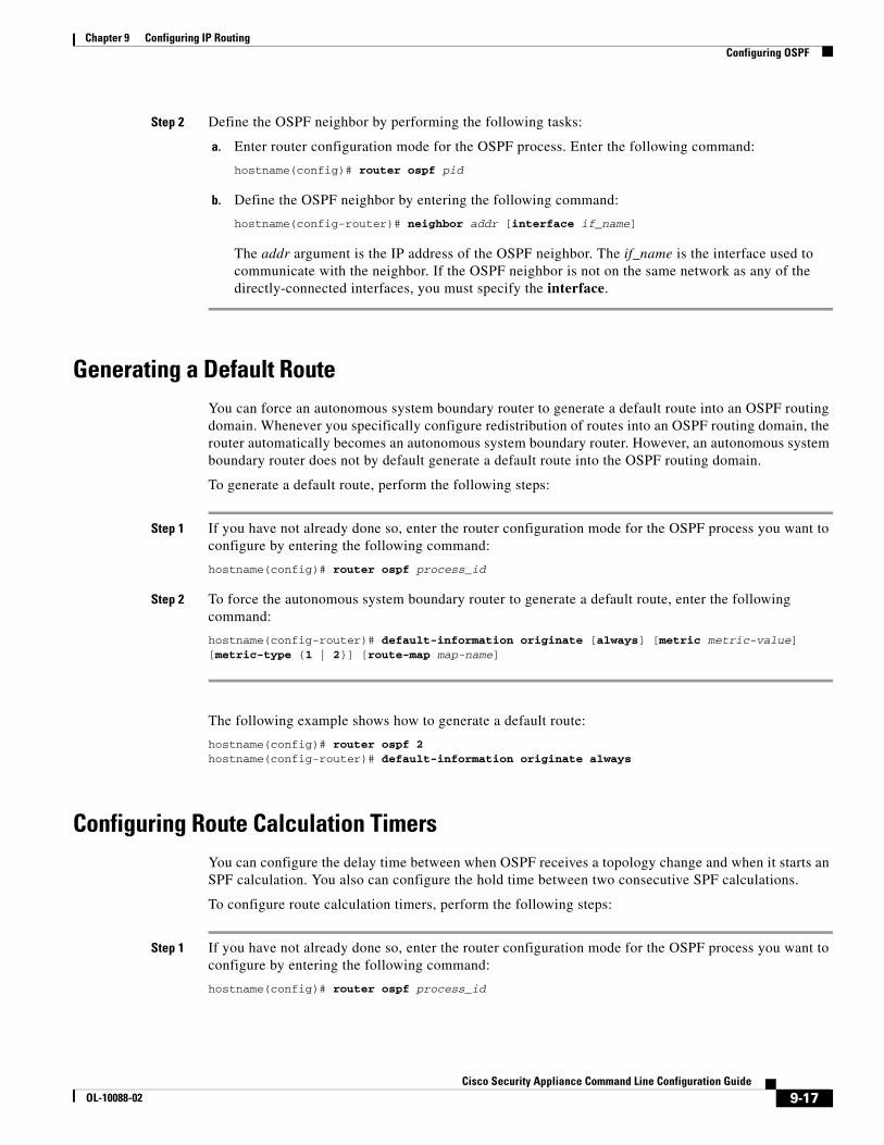
Step 2 Define the OSPF neighbor by performing the following tasks:
a. Enter router configuration mode for the OSPF process. Enter the following command:
hostname(config)# router ospf pid
b. Define the OSPF neighbor by entering the following command:
hostname(config-router)# neighbor addr [interface if_name]
The addr argument is the IP address of the OSPF neighbor. The if_name is the interface used to communicate with the neighbor. If the OSPF neighbor is not on the same network as any of the directly-connected interfaces, you must specify the interface.
Generating a Default RouteYou can force an autonomous system boundary router to generate a default route into an OSPF routing domain. Whenever you specifically configure redistribution of routes into an OSPF routing domain, the router automatically becomes an autonomous system boundary router. However, an autonomous system boundary router does not by default generate a default route into the OSPF routing domain.
To generate a default route, perform the following steps:
Step 1 If you have not already done so, enter the router configuration mode for the OSPF process you want to configure by entering the following command:
hostname(config)# router ospf process_id
Step 2 To force the autonomous system boundary router to generate a default route, enter the following command:
hostname(config-router)# default-information originate [always] [metric metric-value] [metric-type {1 | 2}] [route-map map-name]
The following example shows how to generate a default route:
hostname(config)# router ospf 2hostname(config-router)# default-information originate always
Configuring Route Calculation TimersYou can configure the delay time between when OSPF receives a topology change and when it starts an SPF calculation. You also can configure the hold time between two consecutive SPF calculations.
To configure route calculation timers, perform the following steps:
Step 1 If you have not already done so, enter the router configuration mode for the OSPF process you want to configure by entering the following command:
hostname(config)# router ospf process_id
9-17Cisco Security Appliance Command Line Configuration Guide
OL-10088-02
Chapter 9 Configuring IP Routing Configuring OSPF
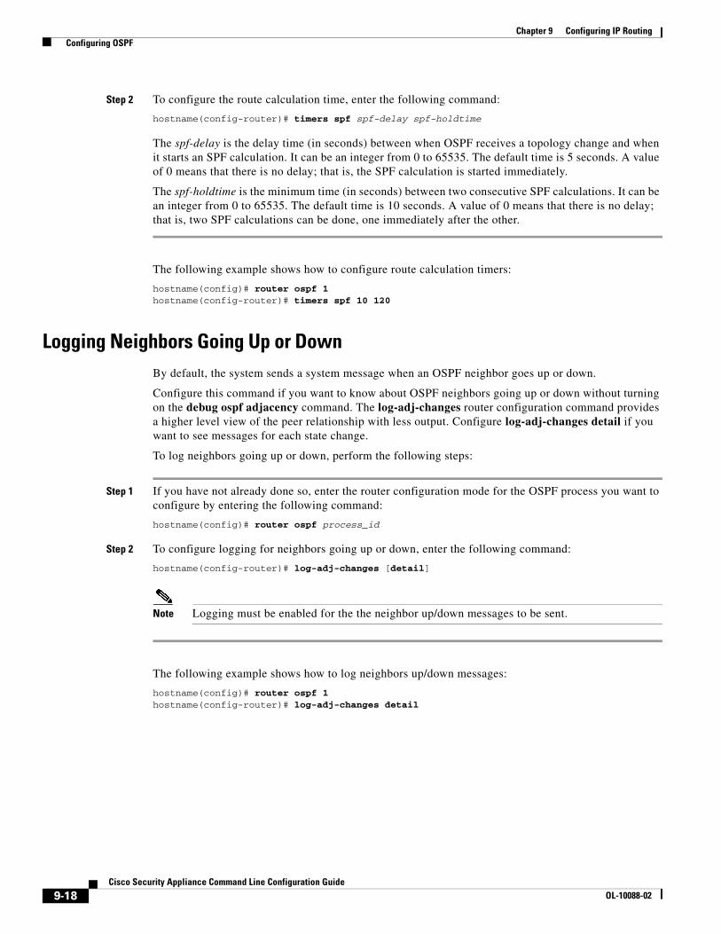
Step 2 To configure the route calculation time, enter the following command:
hostname(config-router)# timers spf spf-delay spf-holdtime
The spf-delay is the delay time (in seconds) between when OSPF receives a topology change and when it starts an SPF calculation. It can be an integer from 0 to 65535. The default time is 5 seconds. A value of 0 means that there is no delay; that is, the SPF calculation is started immediately.
The spf-holdtime is the minimum time (in seconds) between two consecutive SPF calculations. It can be an integer from 0 to 65535. The default time is 10 seconds. A value of 0 means that there is no delay; that is, two SPF calculations can be done, one immediately after the other.
The following example shows how to configure route calculation timers:
hostname(config)# router ospf 1hostname(config-router)# timers spf 10 120
Logging Neighbors Going Up or DownBy default, the system sends a system message when an OSPF neighbor goes up or down.
Configure this command if you want to know about OSPF neighbors going up or down without turning on the debug ospf adjacency command. The log-adj-changes router configuration command provides a higher level view of the peer relationship with less output. Configure log-adj-changes detail if you want to see messages for each state change.
To log neighbors going up or down, perform the following steps:
Step 1 If you have not already done so, enter the router configuration mode for the OSPF process you want to configure by entering the following command:
hostname(config)# router ospf process_id
Step 2 To configure logging for neighbors going up or down, enter the following command:
hostname(config-router)# log-adj-changes [detail]
Note Logging must be enabled for the the neighbor up/down messages to be sent.
The following example shows how to log neighbors up/down messages:
hostname(config)# router ospf 1hostname(config-router)# log-adj-changes detail
9-18Cisco Security Appliance Command Line Configuration Guide
OL-10088-02
Chapter 9 Configuring IP Routing Configuring OSPF
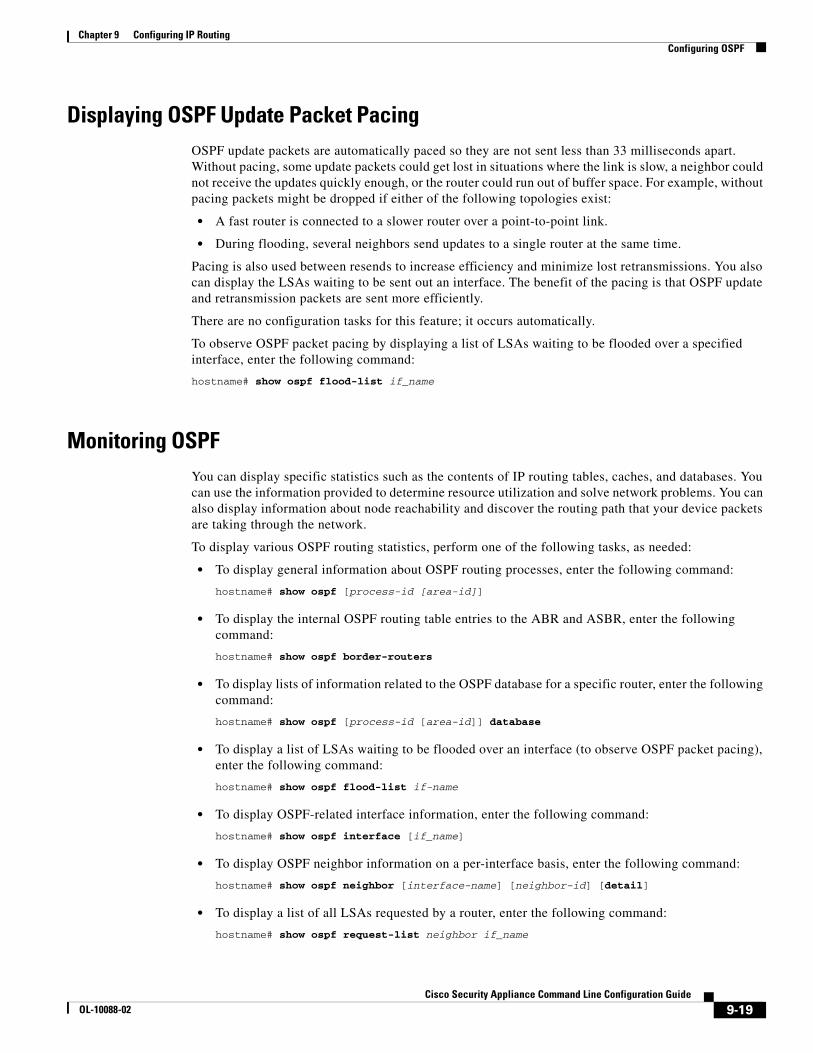
Displaying OSPF Update Packet PacingOSPF update packets are automatically paced so they are not sent less than 33 milliseconds apart. Without pacing, some update packets could get lost in situations where the link is slow, a neighbor could not receive the updates quickly enough, or the router could run out of buffer space. For example, without pacing packets might be dropped if either of the following topologies exist:
• A fast router is connected to a slower router over a point-to-point link.
• During flooding, several neighbors send updates to a single router at the same time.
Pacing is also used between resends to increase efficiency and minimize lost retransmissions. You also can display the LSAs waiting to be sent out an interface. The benefit of the pacing is that OSPF update and retransmission packets are sent more efficiently.
There are no configuration tasks for this feature; it occurs automatically.
To observe OSPF packet pacing by displaying a list of LSAs waiting to be flooded over a specified interface, enter the following command:
hostname# show ospf flood-list if_name
Monitoring OSPFYou can display specific statistics such as the contents of IP routing tables, caches, and databases. You can use the information provided to determine resource utilization and solve network problems. You can also display information about node reachability and discover the routing path that your device packets are taking through the network.
To display various OSPF routing statistics, perform one of the following tasks, as needed:
• To display general information about OSPF routing processes, enter the following command:
hostname# show ospf [process-id [area-id]]
• To display the internal OSPF routing table entries to the ABR and ASBR, enter the following command:
hostname# show ospf border-routers
• To display lists of information related to the OSPF database for a specific router, enter the following command:
hostname# show ospf [process-id [area-id]] database
• To display a list of LSAs waiting to be flooded over an interface (to observe OSPF packet pacing), enter the following command:
hostname# show ospf flood-list if-name
• To display OSPF-related interface information, enter the following command:
hostname# show ospf interface [if_name]
• To display OSPF neighbor information on a per-interface basis, enter the following command:
hostname# show ospf neighbor [interface-name] [neighbor-id] [detail]
• To display a list of all LSAs requested by a router, enter the following command:
hostname# show ospf request-list neighbor if_name
9-19Cisco Security Appliance Command Line Configuration Guide
OL-10088-02

Chapter 9 Configuring IP Routing Configuring RIP
• To display a list of all LSAs waiting to be resent, enter the following command:
hostname# show ospf retransmission-list neighbor if_name
• To display a list of all summary address redistribution information configured under an OSPF process, enter the following command:
hostname# show ospf [process-id] summary-address
• To display OSPF-related virtual links information, enter the following command:
hostname# show ospf [process-id] virtual-links
Restarting the OSPF ProcessTo restart an OSPF process, clear redistribution, or counters, enter the following command:
hostname(config)# clear ospf pid {process | redistribution | counters [neighbor [neighbor-interface] [neighbor-id]]}
Configuring RIPDevices that support RIP send routing-update messages at regular intervals and when the network topology changes. These RIP packets contain information about the networks that the devices can reach, as well as the number of routers or gateways that a packet must travel through to reach the destination address. RIP generates more traffic than OSPF, but is easier to configure.
RIP has advantages over static routes because the initial configuration is simple, and you do not need to update the configuration when the topology changes. The disadvantage to RIP is that there is more network and processing overhead than static routing.
The security appliance supports RIP Version 1 and RIP Version 2.
This section describes how to configure RIP. This section includes the following topics:
• Enabling and Configuring RIP, page 9-20
• Redistributing Routes into the RIP Routing Process, page 9-22
• Configuring RIP Send/Receive Version on an Interface, page 9-22
• Enabling RIP Authentication, page 9-23
• Monitoring RIP, page 9-23
Enabling and Configuring RIPYou can only enable one RIP routing process on the security appliance. After you enable the RIP routing process, you must define the interfaces that will participate in that routing process using the network command. By default, the security appliance sends RIP Version 1 updates and accepts RIP Version 1 and Version 2 updates.
9-20Cisco Security Appliance Command Line Configuration Guide
OL-10088-02
Chapter 9 Configuring IP Routing Configuring RIP
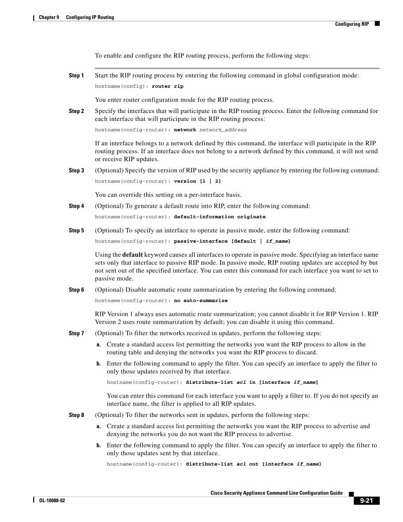
To enable and configure the RIP routing process, perform the following steps:
Step 1 Start the RIP routing process by entering the following command in global configuration mode:
hostname(config): router rip
You enter router configuration mode for the RIP routing process.
Step 2 Specify the interfaces that will participate in the RIP routing process. Enter the following command for each interface that will participate in the RIP routing process:
hostname(config-router): network network_address
If an interface belongs to a network defined by this command, the interface will participate in the RIP routing process. If an interface does not belong to a network defined by this command, it will not send or receive RIP updates.
Step 3 (Optional) Specify the version of RIP used by the security appliance by entering the following command:
hostname(config-router): version [1 | 2]
You can override this setting on a per-interface basis.
Step 4 (Optional) To generate a default route into RIP, enter the following command:
hostname(config-router): default-information originate
Step 5 (Optional) To specify an interface to operate in passive mode, enter the following command:
hostname(config-router): passive-interface [default | if_name]
Using the default keyword causes all interfaces to operate in passive mode. Specifying an interface name sets only that interface to passive RIP mode. In passive mode, RIP routing updates are accepted by but not sent out of the specified interface. You can enter this command for each interface you want to set to passive mode.
Step 6 (Optional) Disable automatic route summarization by entering the following command:
hostname(config-router): no auto-summarize
RIP Version 1 always uses automatic route summarization; you cannot disable it for RIP Version 1. RIP Version 2 uses route summarization by default; you can disable it using this command.
Step 7 (Optional) To filter the networks received in updates, perform the following steps:
a. Create a standard access list permitting the networks you want the RIP process to allow in the routing table and denying the networks you want the RIP process to discard.
b. Enter the following command to apply the filter. You can specify an interface to apply the filter to only those updates received by that interface.
hostname(config-router): distribute-list acl in [interface if_name]
You can enter this command for each interface you want to apply a filter to. If you do not specify an interface name, the filter is applied to all RIP updates.
Step 8 (Optional) To filter the networks sent in updates, perform the following steps:
a. Create a standard access list permitting the networks you want the RIP process to advertise and denying the networks you do not want the RIP process to advertise.
b. Enter the following command to apply the filter. You can specify an interface to apply the filter to only those updates sent by that interface.
hostname(config-router): distribute-list acl out [interface if_name]
9-21Cisco Security Appliance Command Line Configuration Guide
OL-10088-02
Chapter 9 Configuring IP Routing Configuring RIP
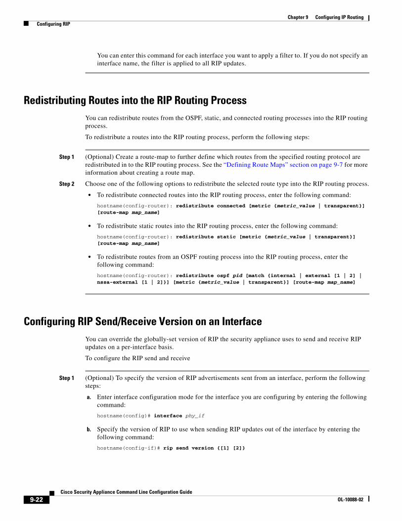
You can enter this command for each interface you want to apply a filter to. If you do not specify an interface name, the filter is applied to all RIP updates.
Redistributing Routes into the RIP Routing ProcessYou can redistribute routes from the OSPF, static, and connected routing processes into the RIP routing process.
To redistribute a routes into the RIP routing process, perform the following steps:
Step 1 (Optional) Create a route-map to further define which routes from the specified routing protocol are redistributed in to the RIP routing process. See the “Defining Route Maps” section on page 9-7 for more information about creating a route map.
Step 2 Choose one of the following options to redistribute the selected route type into the RIP routing process.
• To redistribute connected routes into the RIP routing process, enter the following command:
hostname(config-router): redistribute connected [metric {metric_value | transparent}] [route-map map_name]
• To redistribute static routes into the RIP routing process, enter the following command:
hostname(config-router): redistribute static [metric {metric_value | transparent}] [route-map map_name]
• To redistribute routes from an OSPF routing process into the RIP routing process, enter the following command:
hostname(config-router): redistribute ospf pid [match {internal | external [1 | 2] | nssa-external [1 | 2]}] [metric {metric_value | transparent}] [route-map map_name]
Configuring RIP Send/Receive Version on an InterfaceYou can override the globally-set version of RIP the security appliance uses to send and receive RIP updates on a per-interface basis.
To configure the RIP send and receive
Step 1 (Optional) To specify the version of RIP advertisements sent from an interface, perform the following steps:
a. Enter interface configuration mode for the interface you are configuring by entering the following command:
hostname(config)# interface phy_if
b. Specify the version of RIP to use when sending RIP updates out of the interface by entering the following command:
hostname(config-if)# rip send version {[1] [2]}
9-22Cisco Security Appliance Command Line Configuration Guide
OL-10088-02
Chapter 9 Configuring IP Routing Configuring RIP
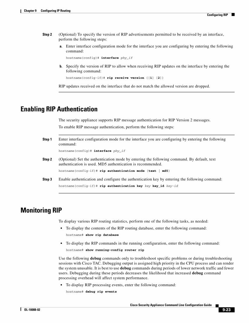
Step 2 (Optional) To specify the version of RIP advertisements permitted to be received by an interface, perform the following steps:
a. Enter interface configuration mode for the interface you are configuring by entering the following command:
hostname(config)# interface phy_if
b. Specify the version of RIP to allow when receiving RIP updates on the interface by entering the following command:
hostname(config-if)# rip receive version {[1] [2]}
RIP updates received on the interface that do not match the allowed version are dropped.
Enabling RIP AuthenticationThe security appliance supports RIP message authentication for RIP Version 2 messages.
To enable RIP message authentication, perform the following steps:
Step 1 Enter interface configuration mode for the interface you are configuring by entering the following command:
hostname(config)# interface phy_if
Step 2 (Optional) Set the authentication mode by entering the following command. By default, text authentication is used. MD5 authentication is recommended.
hostname(config-if)# rip authentication mode {text | md5}
Step 3 Enable authentication and configure the authentication key by entering the following command:
hostname(config-if)# rip authentication key key key_id key-id
Monitoring RIPTo display various RIP routing statistics, perform one of the following tasks, as needed:
• To display the contents of the RIP routing database, enter the following command:
hostname# show rip database
• To display the RIP commands in the running configuration, enter the following command:
hostname# show running-config router rip
Use the following debug commands only to troubleshoot specific problems or during troubleshooting sessions with Cisco TAC. Debugging output is assigned high priority in the CPU process and can render the system unusable. It is best to use debug commands during periods of lower network traffic and fewer users. Debugging during these periods decreases the likelihood that increased debug command processing overhead will affect system performance.
• To display RIP processing events, enter the following command:
hostname# debug rip events
9-23Cisco Security Appliance Command Line Configuration Guide
OL-10088-02
Chapter 9 Configuring IP Routing The Routing Table
• To display RIP database events, enter the following command:
hostname# debug rip database
The Routing TableThis section contains the following topics:
• Displaying the Routing Table, page 9-24
• How the Routing Table is Populated, page 9-24
• How Forwarding Decisions are Made, page 9-26
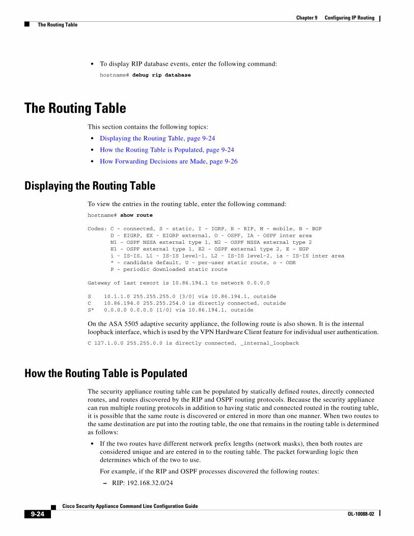
Displaying the Routing TableTo view the entries in the routing table, enter the following command:
hostname# show route
Codes: C - connected, S - static, I - IGRP, R - RIP, M - mobile, B - BGP D - EIGRP, EX - EIGRP external, O - OSPF, IA - OSPF inter area N1 - OSPF NSSA external type 1, N2 - OSPF NSSA external type 2 E1 - OSPF external type 1, E2 - OSPF external type 2, E - EGP i - IS-IS, L1 - IS-IS level-1, L2 - IS-IS level-2, ia - IS-IS inter area * - candidate default, U - per-user static route, o - ODR P - periodic downloaded static route
Gateway of last resort is 10.86.194.1 to network 0.0.0.0
S 10.1.1.0 255.255.255.0 [3/0] via 10.86.194.1, outsideC 10.86.194.0 255.255.254.0 is directly connected, outsideS* 0.0.0.0 0.0.0.0 [1/0] via 10.86.194.1, outside
On the ASA 5505 adaptive security appliance, the following route is also shown. It is the internal loopback interface, which is used by the VPN Hardware Client feature for individual user authentication.
C 127.1.0.0 255.255.0.0 is directly connected, _internal_loopback
How the Routing Table is PopulatedThe security appliance routing table can be populated by statically defined routes, directly connected routes, and routes discovered by the RIP and OSPF routing protocols. Because the security appliance can run multiple routing protocols in addition to having static and connected routed in the routing table, it is possible that the same route is discovered or entered in more than one manner. When two routes to the same destination are put into the routing table, the one that remains in the routing table is determined as follows:
• If the two routes have different network prefix lengths (network masks), then both routes are considered unique and are entered in to the routing table. The packet forwarding logic then determines which of the two to use.
For example, if the RIP and OSPF processes discovered the following routes:
– RIP: 192.168.32.0/24
9-24Cisco Security Appliance Command Line Configuration Guide
OL-10088-02
Chapter 9 Configuring IP Routing The Routing Table
– OSPF: 192.168.32.0/19
Even though OSPF routes have the better administrative distance, both routes are installed in the routing table because each of these routes has a different prefix length (subnet mask). They are considered different destinations and the packet forwarding logic determine which route to use.
• If the security appliance learns about multiple paths to the same destination from a single routing protocol, such as RIP, the route with the better metric (as determined by the routing protocol) is entered into the routing table.
Metrics are values associated with specific routes, ranking them from most preferred to least preferred. The parameters used to determine the metrics differ for different routing protocols. The path with the lowest metric is selected as the optimal path and installed in the routing table. If there are multiple paths to the same destination with equal metrics, load balancing is done on these equal cost paths.
• If the security appliance learns about a destination from more than one routing protocol, the administrative distances of the routes are compared and the routes with lower administrative distance is entered into the routing table.
Administrative distance is a route parameter that security appliance uses to select the best path when there are two or more different routes to the same destination from two different routing protocols. Because the routing protocols have metrics based on algorithms that are different from the other protocols, it is not always possible to determine the “best path” for two routes to the same destination that were generated by different routing protocols.
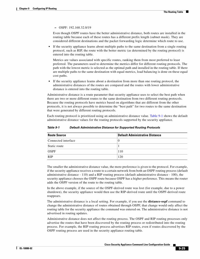
Each routing protocol is prioritized using an administrative distance value. Table 9-1 shows the default administrative distance values for the routing protocols supported by the security appliance.
The smaller the administrative distance value, the more preference is given to the protocol. For example, if the security appliance receives a route to a certain network from both an OSPF routing process (default administrative distance - 110) and a RIP routing process (default administrative distance - 100), the security appliance chooses the OSPF route because OSPF has a higher preference. This means the router adds the OSPF version of the route to the routing table.
In the above example, if the source of the OSPF-derived route was lost (for example, due to a power shutdown), the security appliance would then use the RIP-derived route until the OSPF-derived route reappears.
The administrative distance is a local setting. For example, if you use the distance-ospf command to change the administrative distance of routes obtained through OSPF, that change would only affect the routing table for the security appliance the command was entered on. The administrative distance is not advertised in routing updates.
Administrative distance does not affect the routing process. The OSPF and RIP routing processes only advertise the routes that have been discovered by the routing process or redistributed into the routing process. For example, the RIP routing process advertises RIP routes, even if routes discovered by the OSPF routing process are used in the security appliance routing table.
Table 9-1 Default Administrative Distance for Supported Routing Protocols
Route Source Default Administrative Distance
Connected interface 0
Static route 1
OSPF 110
RIP 120
9-25Cisco Security Appliance Command Line Configuration Guide
OL-10088-02
Chapter 9 Configuring IP Routing Dynamic Routing and Failover
Backup Routes
A backup route is registered when the initial attempt to install the route in the routing table fails because another route was installed instead. If the route that was installed in the routing table fails, the routing table maintenance process calls each routing protocol process that has registered a backup route and requests them to reinstall the route in the routing table. If there are multiple protocols with registered backup routes for the failed route, the preferred route is chosen based on administrative distance.
Because of this process, you can create “floating” static routes that are installed in the routing table when the route discovered by a dynamic routing protocol fails. A floating static route is simply a static route configured with a greater administrative distance than the dynamic routing protocols running on the security appliance. When the corresponding route discover by a dynamic routing process fails, the static route is installed in the routing table.
How Forwarding Decisions are MadeForwarding decisions are made as follows:
• If the destination does not match an entry in the routing table, the packet is forwarded through the interface specified for the default route. If a default route has not been configured, the packet is discarded.
• If the destination matches a single entry in the routing table, the packet is forwarded through the interface associated with that route.
• If the destination matches more than one entry in the routing table, and the entries all have the same network prefix length, the packets for that destination are distributed among the interfaces associated with that route.
• If the destination matches more than one entry in the routing table, and the entries have different network prefix lengths, then the packet is forwarded out of the interface associated with the route that has the longer network prefix length.
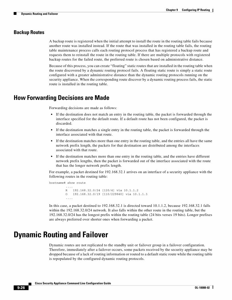
For example, a packet destined for 192.168.32.1 arrives on an interface of a security appliance with the following routes in the routing table:
hostname# show route .... R 192.168.32.0/24 [120/4] via 10.1.1.2 O 192.168.32.0/19 [110/229840] via 10.1.1.3 ....
In this case, a packet destined to 192.168.32.1 is directed toward 10.1.1.2, because 192.168.32.1 falls within the 192.168.32.0/24 network. It also falls within the other route in the routing table, but the 192.168.32.0/24 has the longest prefix within the routing table (24 bits verses 19 bits). Longer prefixes are always preferred over shorter ones when forwarding a packet.
Dynamic Routing and FailoverDynamic routes are not replicated to the standby unit or failover group in a failover configuration. Therefore, immediately after a failover occurs, some packets received by the security appliance may be dropped because of a lack of routing information or routed to a default static route while the routing table is repopulated by the configured dynamic routing protocols.
9-26Cisco Security Appliance Command Line Configuration Guide
OL-10088-02