configuring ipsec vpn - virtual access
TRANSCRIPT

Service Managed GatewayTM
Configuring IPSec VPN
Issue 1.2
Date 12 November 2010

1: Introduction
© 2011 Virtual Access (Irl) Ltd. This material is protected by copyright. No part of this material may be reproduced,
distributed, or altered without the written consent of Virtual Access. All rights reserved. All trademarks, service marks,
registered trademarks and registered service marks are the property of their respective owners. Virtual Access is an ISO 9001 certified company.
Page 2 of 29
1 Introduction ................................................................................................... 3
1.1 What is a VPN? ............................................................................................ 3
1.2 The benefits of an Internet-based VPN ........................................................ 3
1.3 Tunnelling protocols .................................................................................... 4
1.4 Encryption.................................................................................................... 4
1.4.1 DES and 3DES ............................................................................................ 5
1.4.2 Blowfish ..................................................................................................... 5
1.5 Internet Key Exchange (IKE) ....................................................................... 5
1.6 Perfect Forward Secrecy (PFS) .................................................................... 8
1.7 Security Policy Database (SPD) ................................................................... 8
1.8 Digital certificates and signatures ............................................................... 8
1.8.1 Digital certificates ........................................................................................ 8
1.8.2 Digital signatures ........................................................................................ 8
1.9 Preshared key .............................................................................................. 9
1.10 Policies ........................................................................................................ 9
1.11 Tunnel life .................................................................................................... 9
2 Configuring a VPN through your Service Managed Gateway ......................... 11
2.1 Configuring your Gateway connection ....................................................... 11
2.2 Enabling VPN operation ............................................................................. 12
2.3 Configuring a new VPN link ........................................................................ 15
2.4 Configuring a Main Mode connection .......................................................... 15
2.5 Configuring an Aggressive Mode connection .............................................. 23
2.6 Creating a Bypass All policy ....................................................................... 25
2.7 Modifying an existing VPN link ................................................................... 26
2.8 Configuring VPN source address translation .............................................. 27

1: Introduction
©Virtual Access Ltd. Page 3 of 29
1 Introduction
1.1 What is a VPN?
A virtual private network (VPN) is a private data network that uses public communications
resources such as the Internet. To generate a private connection, a VPN uses a tunnelling
protocol to create a secure path, or tunnel, through the public network infrastructure.
Figure 1: VPN Tunnelling
A VPN tunnel has two endpoints, each one consisting of either an individual computer or a
LAN entrance point, such as a gateway or firewall. Usually, VPN tunnels support
� LAN-to-LAN connections such as intranet communication between distributed LAN’s
within a company
� Client-to-LAN connections such as remote access connections for teleworkers
In addition to Tunnelling, a VPN may use an array of authentication and security procedures
to ensure privacy. To guide you through setting up a VPN, Virtual Access provides an easy-
to-use wizard on VPN-enabled Service Managed Gateways.
1.2 The benefits of an internet-based VPN
Traditional private networks require expensive, leased telecommunications lines between
offices. Internet-based VPNs use a cheaply available local Internet connection and avail of
the global Internet structure.

1: Introduction
©Virtual Access Ltd. Page 4 of 29
Using a Virtual Access VPN-enabled Service Managed Gateways makes it simple to install
and maintain VPN connections, and the VPN can easily be scaled to accommodate increasing
connection requirements.
1.3 Tunnelling protocols
Tunnelling protocols protect information by encapsulating data in Internet protocol (IP)
packets that conceal information about source and destination networks. Your VPN-enabled
Service Managed Gateway uses a set of Tunnelling protocols called IP Security (IPsec). This
protocol suite supports two methods of protecting packet information:
� Authentication Header (AH) – this verifies the packet (sender), and provides a means
to confirm that the data has not been altered during transmission:
Figure 2: Authentication Header IP Security
� Encapsulating Security Payload (ESP) – this carries out similar functions to AH, but it
also adds data encryption to ‘hide’ the data, and encapsulates the ciphered packet.
Figure 3: Encapsulating Security Payload IP Security
Your Service Managed Gateway supports both modes.
1.4 Encryption
To protect data, outgoing payload information (message data) from a VPN can be encrypted
before it travels through the public network, and then decrypted at the receiving end. This

1: Introduction
©Virtual Access Ltd. Page 5 of 29
means that even if sensitive data is intercepted as it travels across the public infrastructure,
it is essentially unusable unless the interceptor can decode it.
Your VPN-enabled Service Managed Gateway supports three methods of encryption:
� Data Encryption Standard (DES)
� Triple DES (3DES)
� Blowfish
Whatever algorithm you use, you must ensure that the intended recipient on the VPN can
support the same one.
1.4.1 DES and 3DES
Data Encryption Standard (DES) is a standard, private-key encryption algorithm. It breaks
up outgoing data into blocks, then typically assigns a 56-bit private key to each block
(although it can also support other key lengths). In order to decrypt the data, the recipient
must know the private key used. Although DES has over 70 quadrillion key combinations
and is widely used, it is considered a low-security encryption method. For this reason, the
Internet Key Exchange (IKE) protocol regularly changes the private key automatically in
your Service Managed Gateway.
Triple DES, or 3DES, is a more secure version of DES, where outgoing data is encrypted
three times.
1.4.2 Blowfish
Blowfish, like DES, divides outgoing data into blocks, but it then assigns variable-length
private keys to each block. Again the recipient must know the appropriate key to decipher
the information. If you configure your Service Managed Gateway to use Blowfish, it assigns
128-bit keys, so it is as secure as 3DES, but it is significantly faster.
1.5 Internet Key Exchange (IKE)
To communicate meaningfully across a VPN using DES, 3DES, or Blowfish, the points at each
end of the VPN tunnel must have access to the same encryption keys.
A hybrid protocol called Internet Key Exchange (IKE) establishes and maintains
unidirectional communications in an IPSec environment. Initially, the IKE peers at each end
of the VPN tunnel set up a secure connection for key exchange. This stage is called ‘phase
1’. Using your VPN wizard, you can set phase 1 to ‘main mode’ or to ‘aggressive mode’ on
your Service Managed Gateway.
In main mode, a secure channel is established by sending three packets of data from the
initiator and three from the responder:

1: Introduction
©Virtual Access Ltd. Page 6 of 29
In aggressive mode, a secure channel is set up through two packets from the initiator and
one from the responder. This is faster than main mode, but also less secure:
Figure 4: IKE Aggressive Mode
The next stage of IKE is ‘phase 2’, where the IKE peers negotiate general purpose Security
Associations over the VPN tunnel. This phase uses ‘quick mode’:

1: Introduction
©Virtual Access Ltd. Page 7 of 29
Figure 5: IKE Quick Mode
1: Introduction
©Virtual Access Ltd. Page 8 of 29
1.6 Perfect Forward Secrecy (PFS)
Perfect Forward Secrecy (PFS) is a means of generating new keys that are unrelated to
previously used keys. This means that if an unauthorized party cracks one key, they have no
basis for cracking the next one used. To increase security, your Service Managed Gateway
supports PFS and automatically changes keys regularly.
1.7 Security Policy Database (SPD)
All data passing through your VPN-enabled Gateway is checked against a Security Policy
Database (SPD). Policies held within this database determine the method by which data is
forwarded from the Gateway. Based on the current policy defined, the data is secured and
forwarded, passed on unsecured, or discarded. Your Service Managed Gateway provides an
easy-to-use wizard for defining security policies.
1.8 Digital certificates and signatures
To increase transmission security across a tunnel, a VPN may use methods of authentication
such as digital certificates and signatures.
1.8.1 Digital certificates
Digital certificates issued by a Certification Authority (CA), such as RSA, to individual devices
provide a means by which previously unassociated devices can authenticate themselves to
each other. Certificates identify the device (Service Managed Gateway), supply the device’s
public key, and provide the CA’s identity and public key. By confirming the authenticity of a
certificate received from a third party device, by way of a common, trusted CA, and
comparing the information contained in the certificate with the information provided
separately by the remote device, it is possible to confirm the authenticity of the third party.
Using the embedded web support and a standard Internet browser, you can easily generate
certificate requests and download certificates into your Service Managed Gateway. See the
Certificate option in the Advanced menu of the embedded web.
1.8.2 Digital signatures
Digital signatures authenticate the sender of information, and allow the recipient to check
the integrity of the transmitted data. To create a digital signature, an algorithm uses a
private key to convert a message into a digital code. Your Service Managed Gateway
supports two algorithms for generating digital signatures:
� MD5
� Secure Hash Standard (SHA)
MD5 is an encryption algorithm that creates a digital signature using a one-way hash
function. It converts a message into 128-bit string of digits. The recipient can then decrypt
this code using the private key to check whether the data has been interfered with during
transmission across the public infrastructure.
SHA is another encryption algorithm that generates a digital signature, but it is slightly more
secure than MD5. It creates a 160-bit string that is more difficult to attack, but takes longer

1: Introduction
©Virtual Access Ltd. Page 9 of 29
to generate. The version of SHA that your Service Managed Gateway supports is SHA-1,
which is a higher security revision of the original SHA.
1.9 Preshared key
A preshared key is a secret key used to authenticate each device during IKE negotiation. It
is distinct from the keys used to encrypt data, which are calculated separately by the
devices involved. For successful IKE negotiation, the same preshared key must be entered
on both devices that handle the VPN link.
1.10 Policies
Policies are employed to configure a VPN. Within the Serviced Managed Gateway there are
IKE and SPD policies, the IKE policies specify the criteria used in negotiating Main or
Aggressive mode and SPD policies are used to negotiate Quick Mode.
Before data is presented to the Routing table of the Service Managed Gateway it will be
checked against what is know as an SPD list to check that there is a corresponding policy
matching this data’s characteristics, i.e. it’s source and destination addresses. If there is no
corresponding policy for a particular packet it will be dropped.
When configuring a VPN using the Wizards these policies are configured automatically. For
every VPN configured using the Wizard there are three policies, two of these are SPD
policies, one of which is set to encrypt all data which has a source of the local LAN and a
destination of the Remote side of the far peer. The other SPD Policy is to allow any traffic
which is from the remote side pass onto the local LAN. There is also an IKE policy which
contains the relevant information to negotiate Main or Aggressive mode for that tunnel.
SPD policies have a process attached to them. This process can either be a discard which will
mean that any traffic through the router meeting this policy’s criteria will be dropped. There
is an apply process which means that any traffic which is of this policies type will be
encrypted and sent through the VPN tunnel. Finally there is a bypass policy which states that
any traffic which meets this policies settings will be bypassed any encryption and sent out of
the Router as normal traffic.
When setting up a VPN it is worth noting that there should be a policy set-up which will
accommodate all data passing through the router that is not destined for the far end of the
tunnel.
This policy will allow the data pass from the local side of the Router out to any other
destination beyond the router without the need for encryption. This is known as a bypass all
policy.
1.11 Tunnel life
A tunnel will be established between two peers when there is data trying to travel between
the two LANs. Normally, the tunnel will stay in existence as long as there is data moving
between the two LANs. The tunnel will re-key depending on the SPD (SA) lifetime and re-
negotiate as determined by the IKE lifetime. If there is no data activity at the point of re-
keying, then re-keying will not occur and the tunnel will not be in existence.
This is because it is not needed, as there is no data activity. As soon as there is a data
transfer needed it will re-key and re-establish. If there is a problem with communication

1: Introduction
©Virtual Access Ltd. Page 10 of 29
between the peers, it will be detected using Dead Peer Detection, but only if there is data
activity. If one of the devices determines that the other is 'dead' it will clear the tunnel and
try to re-negotiate.

2: Configuring a VPN through your Service Managed Gateway
©Virtual Access Ltd. Page 11 of 29
2 Configuring a VPN through your SMG
This guide explains how to set up a VPN over an Asymmetric Digital Subscriber Line (ADSL)
service. Even if you are using another service type, this guide will still be instructive because
the installation and configuration of a VPN is standard. You can print out this guide and use
it for reference when you configure a VPN on your Service Managed Gateway.
There are three main steps to setting up a VPN on your Service Managed Gateway:
1. Configuring your Gateway Connection
2. Enabling your VPN operation
3. Configuring your VPN
Throughout the VPN connection procedure, a wizard will prompt you to enter details. It is
advisable to use the wizard to set up your VPN, rather than using the
Expert View. This is because the wizard provides a proven configuration, which
you can then modify using the Expert View if desired.
2.1 Configuring your gateway connection
To enable and configure VPN connections on your Service Managed Gateway, the Gateway
must be correctly installed, and a valid service must be configured on it.
To install your Gateway, see ‘Installing your Service Managed Gateway’. To configure a
service, you use the Fast Start connection wizard – consult Operating your Service
Managed Gateway for details.
This demonstration describes VPN configuration over an ADSL service using ‘Routed PPP
Connection’ as the service type.
2: Configuring a VPN through your Service Managed Gateway
©Virtual Access Ltd. Page 12 of 29
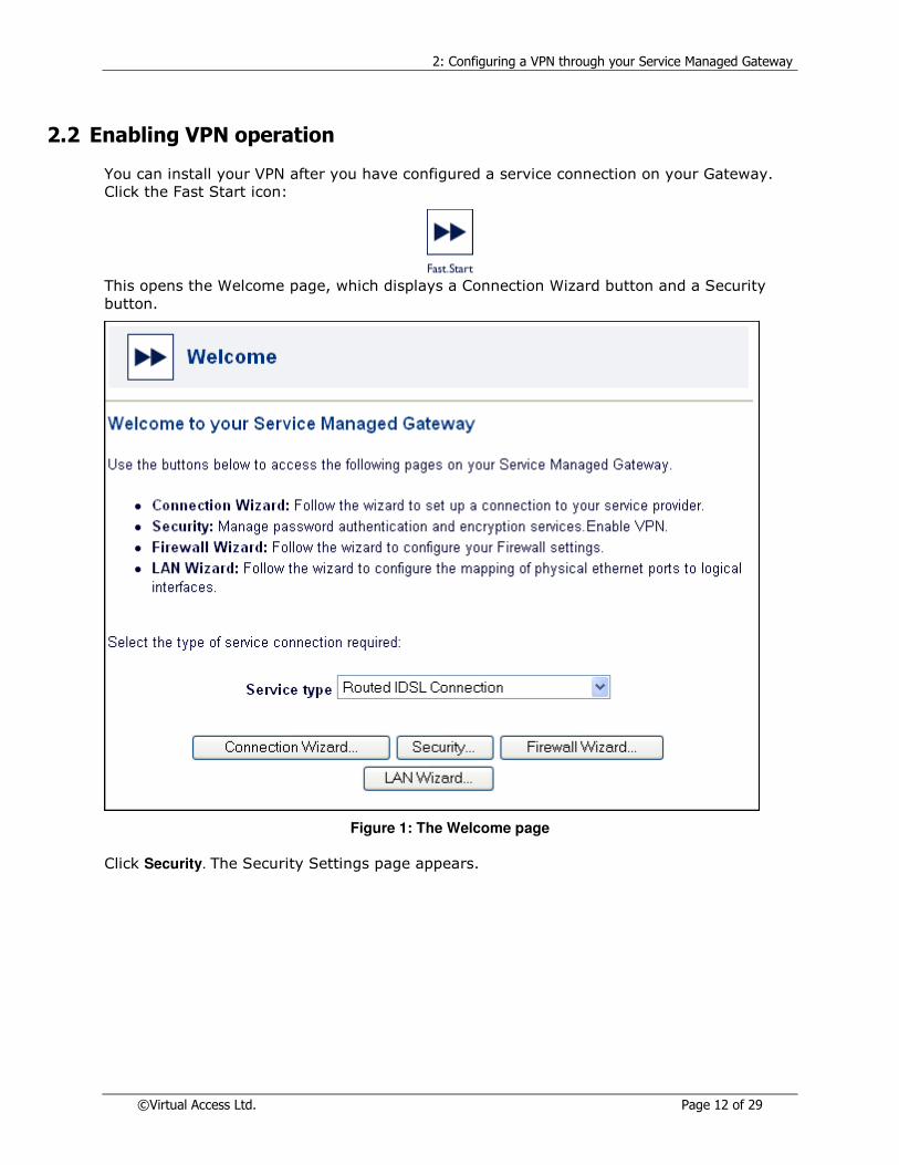
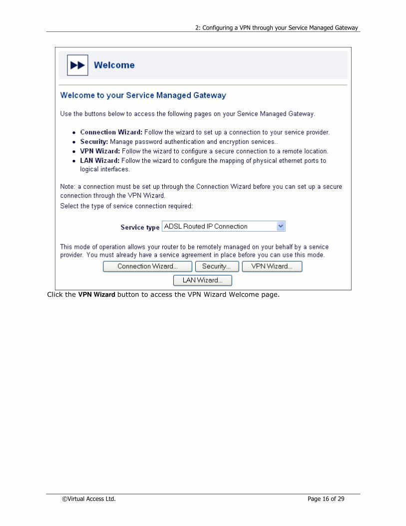
2.2 Enabling VPN operation
You can install your VPN after you have configured a service connection on your Gateway.
Click the Fast Start icon:
This opens the Welcome page, which displays a Connection Wizard button and a Security
button.
Figure 1: The Welcome page
Click Security. The Security Settings page appears.

2: Configuring a VPN through your Service Managed Gateway
©Virtual Access Ltd. Page 13 of 29
Figure 2: The Security Settings window
The table below explains the drop-down lists and fields in the Security Settings page.
VPN Enabled To allow your VPN to be installed, set the ‘VPN enabled’
field to ‘yes’. This will enable the VPN wizard the next
time the Gateway reloads.
VPN Feature Key Note: This field is not present if you purchased a Gateway that is already VPN enabled (as in the figure above). In this case, the feature key is included with the hardware.
If your Service Managed Gateway does not have a pre-
programmed VPN feature key, you may be able to
request one from your Gateway provider. Then you can
enter the key into the ‘VPN feature Key’ field.
Secure Access Only You can configure a secure management connection
with the Gateway by setting this field to ‘yes’. This uses
A Secure Sockets Layer (SSL) protocol to authenticate
the management device to the Gateway. If you do not
require a secure management connection, choose ‘no’
for this field.
Allow Internet Access If you want your Gateway to connect only to the VPN,
set the ‘Allow Internet Access’ to ‘no’. If you want your
Gateway to access general Internet information as well
2: Configuring a VPN through your Service Managed Gateway
©Virtual Access Ltd. Page 14 of 29
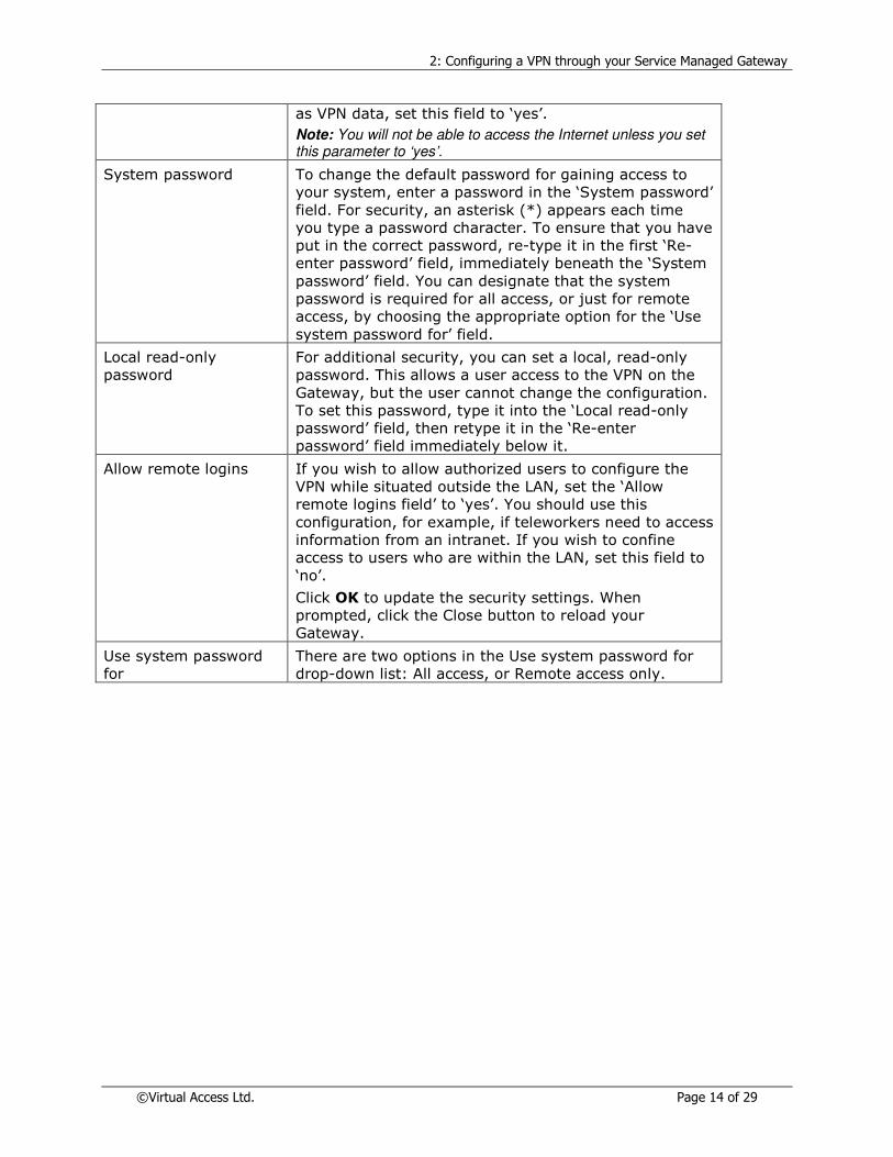
as VPN data, set this field to ‘yes’.
Note: You will not be able to access the Internet unless you set this parameter to ‘yes’.
System password To change the default password for gaining access to
your system, enter a password in the ‘System password’
field. For security, an asterisk (*) appears each time
you type a password character. To ensure that you have
put in the correct password, re-type it in the first ‘Re-
enter password’ field, immediately beneath the ‘System
password’ field. You can designate that the system
password is required for all access, or just for remote
access, by choosing the appropriate option for the ‘Use
system password for’ field.
Local read-only
password
For additional security, you can set a local, read-only
password. This allows a user access to the VPN on the
Gateway, but the user cannot change the configuration.
To set this password, type it into the ‘Local read-only
password’ field, then retype it in the ‘Re-enter
password’ field immediately below it.
Allow remote logins If you wish to allow authorized users to configure the
VPN while situated outside the LAN, set the ‘Allow
remote logins field’ to ‘yes’. You should use this
configuration, for example, if teleworkers need to access
information from an intranet. If you wish to confine
access to users who are within the LAN, set this field to
‘no’.
Click OK to update the security settings. When
prompted, click the Close button to reload your
Gateway.
Use system password
for
There are two options in the Use system password for
drop-down list: All access, or Remote access only.
2: Configuring a VPN through your Service Managed Gateway
©Virtual Access Ltd. Page 15 of 29
2.3 Configuring a new VPN link
As previously discussed, there are two types of VPN negotiations that can be configured. The
difference between the two is the manner in which the first stage in negotiations takes
place. The two options are to have a six-stage negotiation process (Main mode) or a three
stage one (Aggressive mode).
The choice between which process to use is determined by the scenario and set-up required.
If the user is running a Serviced Managed Gateway with a dynamic IP address scheme for
example, then it will be necessary to configure the set-up using aggressive mode.
Both methods of configuration are dealt with in the following section.
2.4 Configuring a Main Mode connection
Once you have VPN-enabled your Gateway, you can configure one or more VPN connections
on it. To access the VPN wizard, first click the Fast Start icon:
The Welcome page appears.
2: Configuring a VPN through your Service Managed Gateway
©Virtual Access Ltd. Page 16 of 29
Click the VPN Wizard button to access the VPN Wizard Welcome page.

2: Configuring a VPN through your Service Managed Gateway
©Virtual Access Ltd. Page 17 of 29
In the drop-down menu, ensure that ‘Add a new standard vpn link’ is visible. If the name of
an existing VPN is shown, choose ‘Add a new standard vpn link’ from the menu. Now click Next to open the VPN Configuration page.
You must configure a separate VPN link for each remote site with which you want to
establish a connection. To do this, you simply set up one link at a time, repeating the
process described in the following sections.
If you are using a Service Managed Gateway at a remote site, you must configure a
corresponding reverse connection for each link that you set up. To do this, you use the
processes described here on the remote device.

2: Configuring a VPN through your Service Managed Gateway
©Virtual Access Ltd. Page 18 of 29
Now enter the IP details that relate to the VPN link you are configuring.
Ensure that the correct name appears in the Link Name field. Then, using the diagram below
as a guide, enter the relevant IP addresses, subnet addresses, and mask details.
1 = Local WAN IP Address
2 = Remote WAN IP Address
2: Configuring a VPN through your Service Managed Gateway
©Virtual Access Ltd. Page 19 of 29
3 = Local LAN Subnet Address/Mask
4 = Remote LAN Subnet Address/Mask
Enter the preshared key in the Preshared Key field. Then re-enter it in the Preshared Key
Confirmed field to confirm that it is correct.
At this point there is enough data provided for a Main Mode connection to connect as long as
the correct information is entered on the corresponding device at the far end of the tunnel.
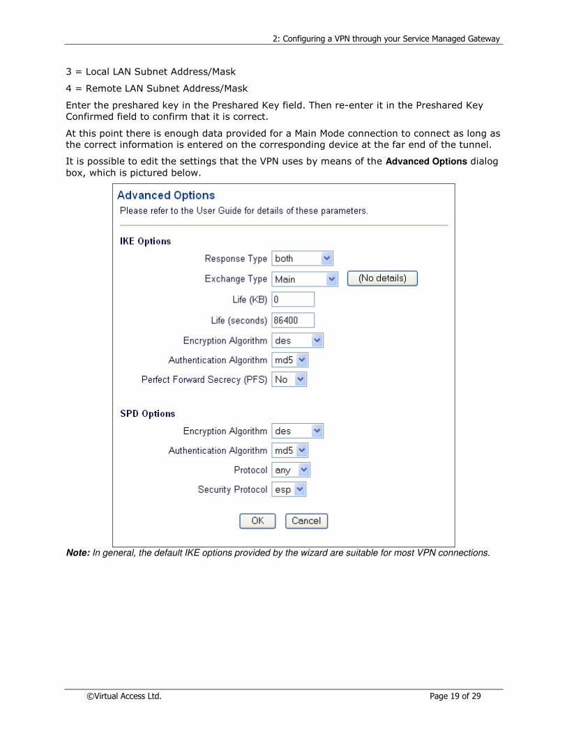
It is possible to edit the settings that the VPN uses by means of the Advanced Options dialog
box, which is pictured below.
Note: In general, the default IKE options provided by the wizard are suitable for most VPN connections.

2: Configuring a VPN through your Service Managed Gateway
©Virtual Access Ltd. Page 20 of 29
The table below explains the drop-down lists and fields in the Advanced Options page.
IKE Options
Response type This field enables you to configure the initial setup of the
VPN connection. To allow only outgoing messages, but not
incoming packets, choose ‘initiator’ from the drop-down
menu. To allow only incoming data and prevent messages
being sent through the VPN connection, set the field to
‘responder’. To permit two-way communication through the
connection, choose ‘both’ from the drop-down menu.
Exchange type You use this field to set the mode of IKE phase 1. You can
choose either ‘main’ or ‘aggressive’. See next section for
details on configuring this type of connection.
Life (KB/seconds) This section determines how often the VPN will renegotiate
the tunnel through which the encrypted data is traveling.
The renegotiation can be triggered by either a given amount
of time passing or by the amount of data that passes
through the tunnel. The default is to 86400 seconds (24
hours) which means that after every day if traffic is
continuously passing through the VPN tunnel it will
renegotiate the encryption key it uses.
Encryption Algorithm You set the IKE encryption algorithm by choosing ‘des’,
‘3des’, or ‘blowfish’ from the drop-down menu. Whichever
algorithm you choose, you should ensure that it is supported
by intended recipients on the VPN.
Authentication
Algorithm
This field lets you set the encryption algorithm used to
generate the digital signature. You can choose either ‘md5’
or ‘sha’. See Authentication for more details.
PFS To increase security by enabling Perfect Forward Secrecy
(PFS), set this parameter to ‘yes’. To disable it, you set it to
‘no’. Under most circumstances, you should not change the
default setting for this field on the Gateway, as it can lead to
compatibility issues.
SPD Options
Encryption Algorithm You set the SPD encryption algorithm by choosing ‘des’,
‘3des’, or ‘blowfish’ from the drop-down menu. You may also
choose not to use an encryption algorithm here. In this case,
you set the field to ‘null’.
Authentication
Algorithm
You set an encryption algorithm by choosing ‘md5’, ‘sha’, or
‘des’ from the drop-down menu as appropriate. See
Authentication for more details.
Protocol You can choose to limit SPD handling to a single protocol by
choosing one from the drop-down menu. However, to
maximize the variety of packets that the SPD can process
successfully, you should set this field to ‘any’.
Security Protocol To implement a security protocol on the SPD, you choose
‘esp’ or ‘ah’ from the drop-down menu.

2: Configuring a VPN through your Service Managed Gateway
©Virtual Access Ltd. Page 21 of 29
When you have configured the IKE and SPD options, click OK to close the Advanced Options window and return to the VPN Connections Configuration page. Now click Next to open the
Finished page.
To implement the new VPN connection, click Save configuration. Your Gateway now reloads
with the updated VPN configuration.

2: Configuring a VPN through your Service Managed Gateway
©Virtual Access Ltd. Page 22 of 29
Click Finish to return to the Start page.

2: Configuring a VPN through your Service Managed Gateway
©Virtual Access Ltd. Page 23 of 29
2.5 Configuring an aggressive mode connection
The most common application of Aggressive mode connections is in use on tunnels where
one side is using a dynamic addressing scheme. In the previous example when configuring a
Main mode connection we saw how we specified a local WAN IP address. Evidently we
cannot enter in a parameter in this field if this address is not known and may be subject to
change. Therefore some other mechanism must be put in place so that the side that has the
dynamic address may to identify itself.
In this scenario a predefined user name or string is specified (normally an e-mail address or
a URL).
Note: Only one side of the VPN tunnel may have a dynamic address - there must always be a static address on the far side of the tunnel. It follows from this that only the side which has the dynamic address may initiate the negotiations as it knows the address of the far side of the tunnel whereas the end with the static address does not.
The following configuration set-up is from the point of view of the Tunnel endpoint which has
a dynamic address attached to it.
In order to configure an Aggressive mode connection it is necessary to make changes to the
configuration via the Expert View Web Interface on the Serviced Managed Gateway. User
discretion is advised when deciding on either sole use of the expert view or using the Wizard
to configure the basic parameters of the link and then using expert view to edit the
necessary properties afterwards.
We will deal with editing a VPN configuration which was created using the Wizard as detailed
previously.
When using the Wizard to configure part of an Aggressive mode connection the user should
leave Local WAN IP Address to 0.0.0.0 as this field is no longer used in the scenario detailed.
Having filled in the relevant information for Remote WAN IP address and the two subnets
which the VPN tunnel will connect the user should proceed to the advanced menu where the
exchange type should be changed to Aggressive as opposed to Main.
At this point the user should proceed through the confirmation steps of closing the Advanced
Window and clicking the Next button on the Connection Wizard page. To avoid unnecessary
reloads the user should at this point before saving the configuration proceed to the Expert
View of the Serviced Managed Gateway and go to System>VPN>IKE.
From here the user should go the IKE policy corresponding to the one configured using the
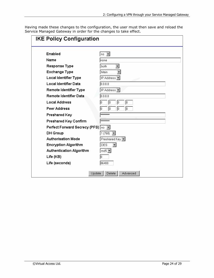
Wizard. From this menu the user will have to make the following changes.
The Response type should be set to Initiator as this Serviced Managed Gateway will be the
only side of the VPN which is capable of starting up negotiations.
The default for Local Identifier Type is IP Address, and the Wizard will default the Remote
Identifier Type to be that of the peer Address. For an aggressive mode connection however
IP addresses can not be used as the Identifier type or data therefore this should be set to
either DNS or e-mail. In the example shown below e-mail is selected. When setting this, this
means that regardless of what the WAN IP address of the Serviced Managed Gateway is, it
will use the e-mail specified to identify itself. As is the case with all parameters on a VPN
set-up the converse settings must be applied on the remote end. That is to say that in this
example the local Identifier data on one side must the remote on the other and vice-versa.
Also the far end should be set to ‘Responder’ as it will only be capable of accepting requests
for negotiations.
2: Configuring a VPN through your Service Managed Gateway
©Virtual Access Ltd. Page 24 of 29
Having made these changes to the configuration, the user must then save and reload the
Service Managed Gateway in order for the changes to take effect.

2: Configuring a VPN through your Service Managed Gateway
©Virtual Access Ltd. Page 25 of 29
2.6 Creating a bypass all policy
As has been previously discussed, when a Serviced Managed Gateway is configured as part
of a VPN tunnel all traffic passing through it is checked for a corresponding policy, if one
does not match this data type it will be dropped.
Therefore there is a need to have a policy in place which accommodates for all traffic not
bound for the VPN tunnel.
Policies have a priority attached to them. If a policy has a high priority then all traffic will be
checked against this policy first. It is therefore advisable that when configuring a VPN the
policy which is set to encrypt specific traffic should have a high priority so all traffic is
checked against this policy first. This leads to the conclusion that the ‘bypass all’ policy
should have a low priority so that only traffic which is not destined to be encrypted get
checked against this policy.
To enter in this policy the user must go to the Expert View Interface on the Serviced
Managed Gateway. From here they should select System>VPN>SPD 1-50.
The user should then choose an unused SPD Policy and select the add function.

2: Configuring a VPN through your Service Managed Gateway
©Virtual Access Ltd. Page 26 of 29
As can be seen from the diagram below a process of ‘Bypass’ is set, the priority is set to 10
(A suitably low number), protocol is set to ‘all’ and all addresses are set to 0’s which means
it will match any data type.
The parameters are set and the bypass policy is configured. Click Update to save the
settings to the SMG.
2.7 Modifying an existing VPN link
You can use the VPN wizard to alter the setup of an existing VPN connection on your Service
Managed Gateway. To open the VPN wizard on your service-enabled Gateway, first click the
Fast Start icon.
On the Welcome page, click the VPN Wizard button to open the VPN Wizard Welcome page.

2: Configuring a VPN through your Service Managed Gateway
©Virtual Access Ltd. Page 27 of 29
From the drop-down menu, choose the name of the link that you wish to modify, then click Next to open the Configuration page.
Now you can alter the parameter settings of the VPN link and save the new configuration as
described in ‘Configuring a new VPN link’.
2.8 Configuring VPN source address translation
When you configure a VPN you should have different subnets at each end of the VPN tunnel,
to prevent address conflicts between the two networks. However, if the VPN is connecting
two LANs which have been set up for some time and cannot be changed, conflicts might still
occur.
VPN source address translation enables an SMG to translate its local LAN to another address
range when transmitting through a VPN. This mechanism works on a direct one-to-one
address translation.
An IP address has two components, the network address and the host address. Masks
determine what subnet an IP address belongs to. For example, consider the IP address

2: Configuring a VPN through your Service Managed Gateway
©Virtual Access Ltd. Page 28 of 29
192.168.100.100. If this is part of a Class C (255.255.255.0) network, the first three
numbers (192.168.100) represent the Class C network address, and the last number (100)
identifies a particular host on this network.
To implement VPN source address translation, you configure one VPN source address on the
local SMG LAN port. The SMG will then use the subnet mask of the VPN source address
interface to translate all addresses on the local LAN.
For example, suppose the SMG has an IP address of 192.168.100.1 configured on eth-0.
This interface has a subnet mask of 255.255.255.0 and a VPN source address of 10.1.1.1.
This means that for every host on the LAN the SMG will translate 192.168.100.XXX to
10.1.1.XXX. The SMG will only translate the network address, but will leave the host
addresses for each device unchanged. Therefore a complete LAN translation can take place.
To configure VPN source address translation, you must set the IP address on the interface
where the local LAN is located. Generally this can be assumed to be eth-0 as this is the
default local IP address, although this is not always the case.
To set the VPN source address in the SMG, click Expert View and navigate to interfaces –
eth-0 – ip – ip. Then click the Advanced button on the LAN IP Interface on eth-0 page.

2: Configuring a VPN through your Service Managed Gateway
©Virtual Access Ltd. Page 29 of 29
After you set up the source address, you can configure the SMG to support a VPN using
either its standard local IP address range or the VPN source address range. You do not need
to configure the IP subnet mask as the SMG will take this from the subnet mask specified on
the interface itself.
When using VPN source address translation, you must configure the SPD settings on the
SMG using the VPN source addresses. This means that the source start and end addresses
should be the VPN source address configured on the interface. The SMG will then translate
all addresses automatically before sending traffic down the VPN.