configuring main system - argseguridad
TRANSCRIPT
CHAPTER
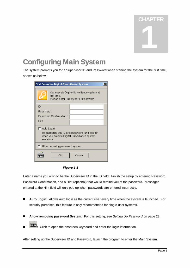
1 Configuring Main System The system prompts you for a Supervisor ID and Password when starting the system for the first time,
shown as below:
Figure 1-1
Enter a name you wish to be the Supervisor ID in the ID field. Finish the setup by entering Password,
Password Confirmation, and a Hint (optional) that would remind you of the password. Messages
entered at the Hint field will only pop up when passwords are entered incorrectly.
Auto Login: Allows auto login as the current user every time when the system is launched. For
security purposes, this feature is only recommended for single-user systems.
Allow removing password System: For this setting, see Setting Up Password on page 28.
: Click to open the onscreen keyboard and enter the login information.
After setting up the Supervisor ID and Password, launch the program to enter the Main System.
Page 1
Chapter 1: Configuring Main System
1 2
34
5
6
7
8
915
1112 101617
1314
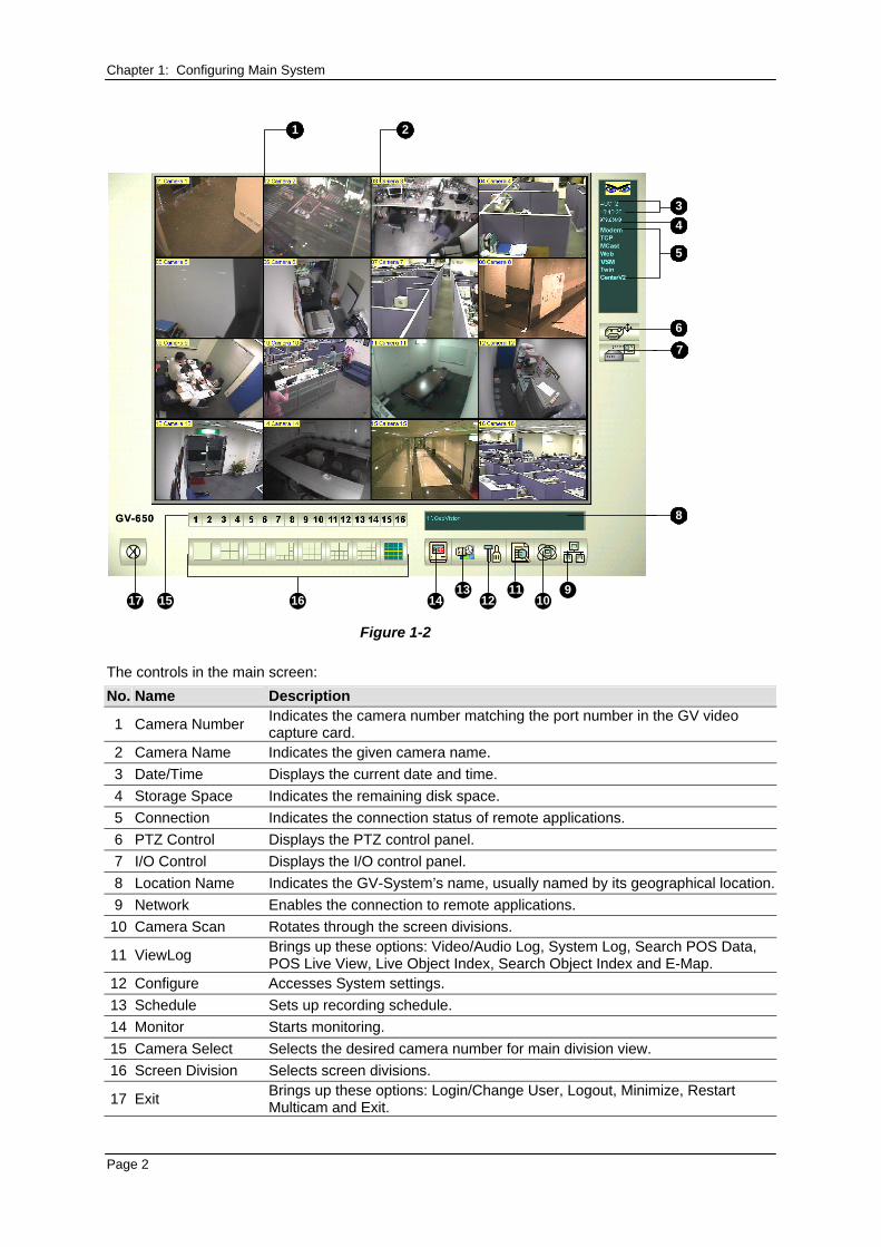
Figure 1-2 The controls in the main screen: No. Name Description
1 Camera Number Indicates the camera number matching the port number in the GV video capture card.
2 Camera Name Indicates the given camera name. 3 Date/Time Displays the current date and time. 4 Storage Space Indicates the remaining disk space. 5 Connection Indicates the connection status of remote applications. 6 PTZ Control Displays the PTZ control panel. 7 I/O Control Displays the I/O control panel. 8 Location Name Indicates the GV-System’s name, usually named by its geographical location. 9 Network Enables the connection to remote applications.
10 Camera Scan Rotates through the screen divisions.
11 ViewLog Brings up these options: Video/Audio Log, System Log, Search POS Data, POS Live View, Live Object Index, Search Object Index and E-Map.
12 Configure Accesses System settings. 13 Schedule Sets up recording schedule. 14 Monitor Starts monitoring. 15 Camera Select Selects the desired camera number for main division view. 16 Screen Division Selects screen divisions.
17 Exit Brings up these options: Login/Change User, Logout, Minimize, Restart Multicam and Exit.
Page 2
Chapter 1: Configuring Main System Press [F7] on the keyboard, or click the Monitor button to start recording. By default, every camera
records with the following settings:
In Motion Detection mode
With the 320 x 240 resolution
With Geo Mpeg4 codec
When working with the system, you will undoubtedly want to change the settings as you go along.
The buttons provide quick access to several popular Main System settings. Click any button to see
the menus to these settings. Let’s start with the Configure button.
System Configuration
Click the Configure button and select System Configure. You may configure cameras and global
recording parameters in this dialog box. Changes made to the General Setting tab would apply to all
available cameras attached to the system, while changes made to each camera tab apply only to the
individual camera. In I/O Device tab you could add and configure I/O devices. HotLine/Network tab is
used to configure the system for connection to network or mobile.
Page 3
Chapter 1: Configuring Main System
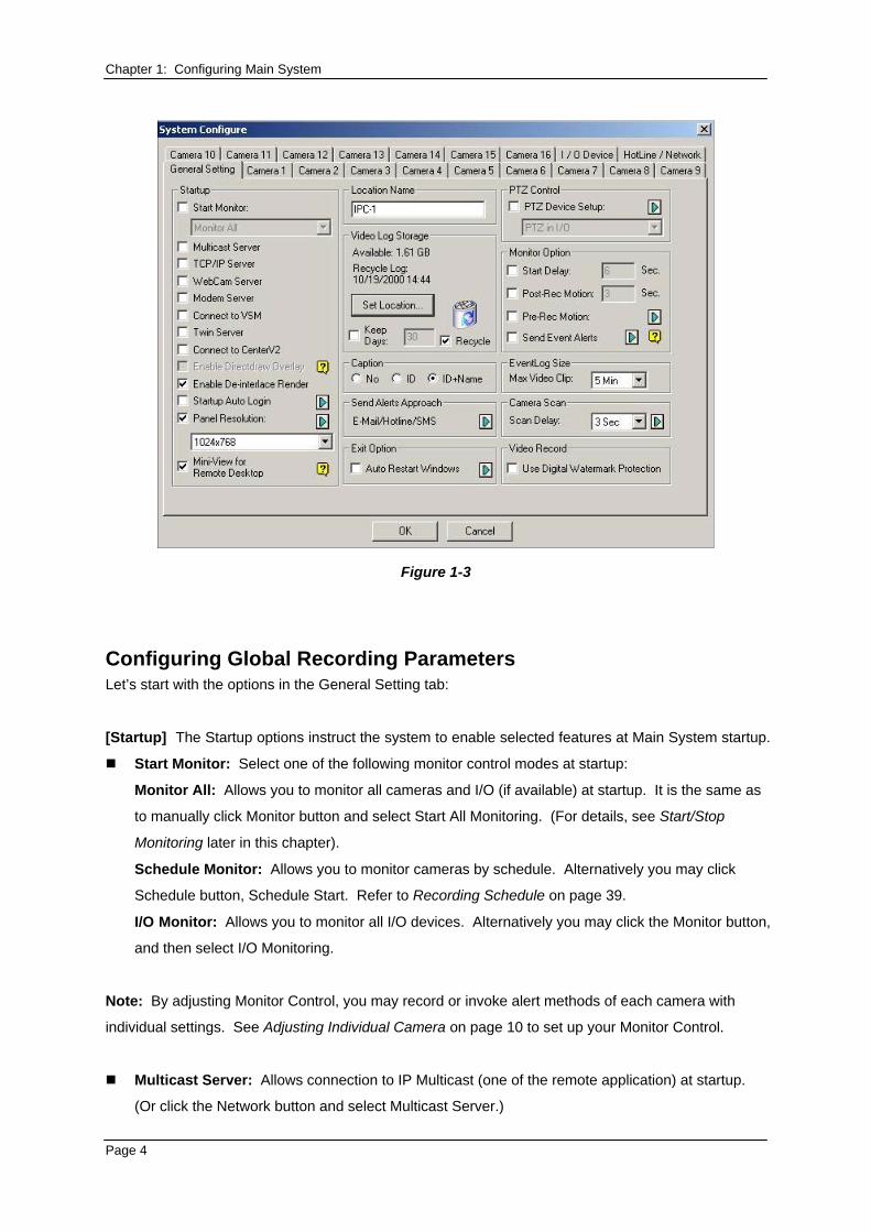
Figure 1-3
Configuring Global Recording Parameters Let’s start with the options in the General Setting tab:
[Startup] The Startup options instruct the system to enable selected features at Main System startup.
Start Monitor: Select one of the following monitor control modes at startup:
Monitor All: Allows you to monitor all cameras and I/O (if available) at startup. It is the same as
to manually click Monitor button and select Start All Monitoring. (For details, see Start/Stop
Monitoring later in this chapter).
Schedule Monitor: Allows you to monitor cameras by schedule. Alternatively you may click
Schedule button, Schedule Start. Refer to Recording Schedule on page 39.
I/O Monitor: Allows you to monitor all I/O devices. Alternatively you may click the Monitor button,
and then select I/O Monitoring.
Note: By adjusting Monitor Control, you may record or invoke alert methods of each camera with
individual settings. See Adjusting Individual Camera on page 10 to set up your Monitor Control.
Multicast Server: Allows connection to IP Multicast (one of the remote application) at startup.
(Or click the Network button and select Multicast Server.)
Page 4
Chapter 1: Configuring Main System TCP Server: Allows connection to Remote View (another remote application) by TCP. (Or click
the Network button and select TCP Server.)
WebCam Server: Allows connection to WebCam Server at startup. (Or click the Network
button and select WebCam Server.)
Modem Server: Allows connection to Remote View by a modem. (Or click the Network button
and select Modem Server.)
Connect to VSM: Allows connection to VSM Server (Or click the Network button and select
Connect to VSM.)
Twin Server: Allows connection to Twin Server at startup. (Or click the Network button and
select Twin Server). Twin Server is discussed in Chapter 11.
Connect to CenterV2: Allows connection to CenterV2. (Or click the Network button and select
Connect to CenterV2.)
Enable Directdraw Overlay: Enables full-screen at startup. (For the related applications, see
Switching to Full-Screen View later in this chapter).
Enable De-interlace Render: Avoids interlace of the odd and even video lines. This feature
affects only single view mode with the resolution of 640 x 480 and 720 x 480. After enabling the
feature, you must restart the GV-System to apply it.
Note:
1. The Enable Directdraw Overlay and De-interlace Render features can greatly enhance image
quality. If your VGA card supports DirectX9, enable both settings.
2. You may see a warning message “Directdraw Create Overlay Failed” when trying to use
WebCam Remote Control to connect to a server. The message indicates the server has the
Enable Directdraw Overlay feature enabled. It only means the remote side will not see the
images with DirectDraw applied. It is safe to press YES to continue the connection.
Tip: To check the version of your DirectX, search for the file name dxdiag. Open the file and find the
related information. DirectX 9.0C is also included in the Surveillance System Software CD.
Startup Auto Login: Select and press the Arrow button to assign an ID used at system auto
startup. After the setup, the system will automatically login using this ID at next startup, without
asking for ID and Password. For related settings, see Launching GV-System from System Tray
on page 19.
Panel Resolution: Select the resolution from the drop-down list that best fits your computer
monitor screen.
Page 5
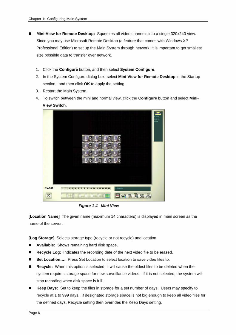
Chapter 1: Configuring Main System Mini-View for Remote Desktop: Squeezes all video channels into a single 320x240 view.
Since you may use Microsoft Remote Desktop (a feature that comes with Windows XP
Professional Edition) to set up the Main System through network, it is important to get smallest
size possible data to transfer over network.
1. Click the Configure button, and then select System Configure.
2. In the System Configure dialog box, select Mini-View for Remote Desktop in the Startup
section, and then click OK to apply the setting.
3. Restart the Main System.
4. To switch between the mini and normal view, click the Configure button and select Mini-
View Switch.
Figure 1-4 Mini View
[Location Name] The given name (maximum 14 characters) is displayed in main screen as the
name of the server.
[Log Storage] Selects storage type (recycle or not recycle) and location.
Available: Shows remaining hard disk space.
Recycle Log: Indicates the recording date of the next video file to be erased.
Set Location…: Press Set Location to select location to save video files to.
Recycle: When this option is selected, it will cause the oldest files to be deleted when the
system requires storage space for new surveillance videos. If it is not selected, the system will
stop recording when disk space is full.
Keep Days: Set to keep the files in storage for a set number of days. Users may specify to
recycle at 1 to 999 days. If designated storage space is not big enough to keep all video files for
the defined days, Recycle setting then overrides the Keep Days setting.
Page 6
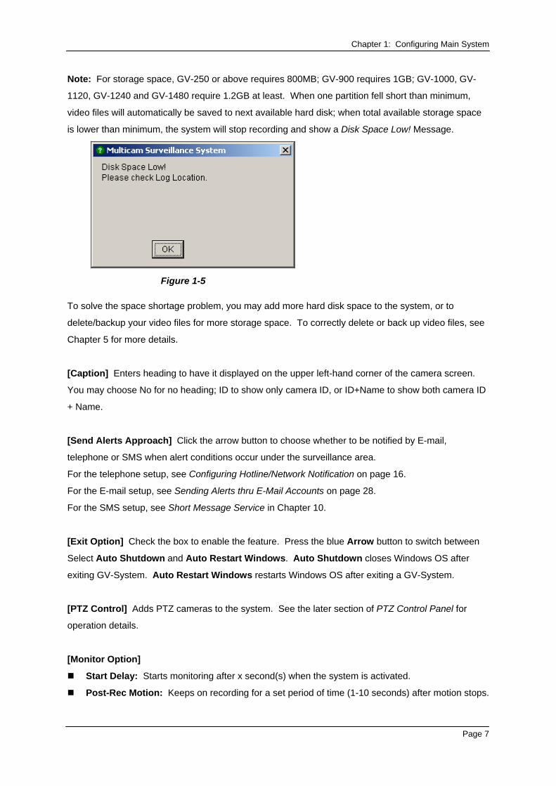
Chapter 1: Configuring Main System Note: For storage space, GV-250 or above requires 800MB; GV-900 requires 1GB; GV-1000, GV-
1120, GV-1240 and GV-1480 require 1.2GB at least. When one partition fell short than minimum,
video files will automatically be saved to next available hard disk; when total available storage space
is lower than minimum, the system will stop recording and show a Disk Space Low! Message.
Figure 1-5
To solve the space shortage problem, you may add more hard disk space to the system, or to
delete/backup your video files for more storage space. To correctly delete or back up video files, see
Chapter 5 for more details.
[Caption] Enters heading to have it displayed on the upper left-hand corner of the camera screen.
You may choose No for no heading; ID to show only camera ID, or ID+Name to show both camera ID
+ Name.
[Send Alerts Approach] Click the arrow button to choose whether to be notified by E-mail,
telephone or SMS when alert conditions occur under the surveillance area.
For the telephone setup, see Configuring Hotline/Network Notification on page 16.
For the E-mail setup, see Sending Alerts thru E-Mail Accounts on page 28.
For the SMS setup, see Short Message Service in Chapter 10.
[Exit Option] Check the box to enable the feature. Press the blue Arrow button to switch between
Select Auto Shutdown and Auto Restart Windows. Auto Shutdown closes Windows OS after
exiting GV-System. Auto Restart Windows restarts Windows OS after exiting a GV-System.
[PTZ Control] Adds PTZ cameras to the system. See the later section of PTZ Control Panel for
operation details.
[Monitor Option]
Start Delay: Starts monitoring after x second(s) when the system is activated.
Post-Rec Motion: Keeps on recording for a set period of time (1-10 seconds) after motion stops.
Page 7
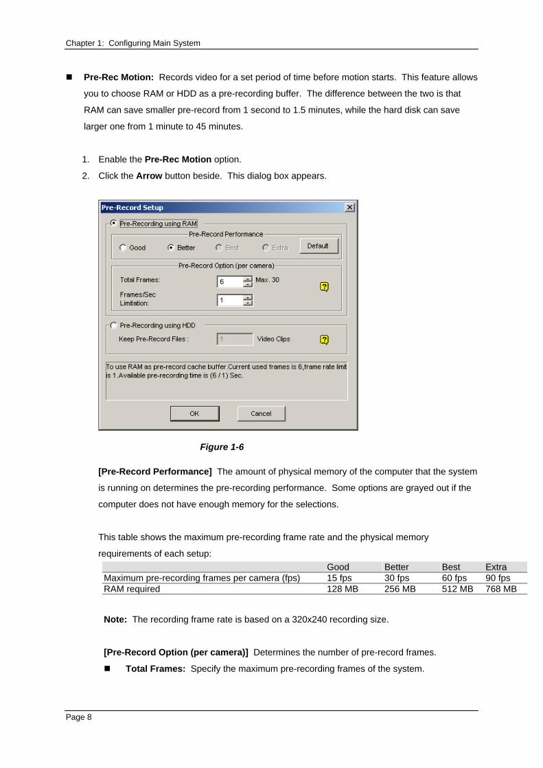
Chapter 1: Configuring Main System Pre-Rec Motion: Records video for a set period of time before motion starts. This feature allows
you to choose RAM or HDD as a pre-recording buffer. The difference between the two is that
RAM can save smaller pre-record from 1 second to 1.5 minutes, while the hard disk can save
larger one from 1 minute to 45 minutes.
1. Enable the Pre-Rec Motion option.
2. Click the Arrow button beside. This dialog box appears.
Figure 1-6
[Pre-Record Performance] The amount of physical memory of the computer that the system
is running on determines the pre-recording performance. Some options are grayed out if the
computer does not have enough memory for the selections.
This table shows the maximum pre-recording frame rate and the physical memory
requirements of each setup: Good Better Best Extra Maximum pre-recording frames per camera (fps) 15 fps 30 fps 60 fps 90 fps RAM required 128 MB 256 MB 512 MB 768 MB
Note: The recording frame rate is based on a 320x240 recording size.
[Pre-Record Option (per camera)] Determines the number of pre-record frames.
Total Frames: Specify the maximum pre-recording frames of the system.
Page 8
Chapter 1: Configuring Main System
Frame/Sec Limitation: Specify the maximum pre-recording frame rate (fps) of a
camera.
Dividing the Total Frames by Frames/Sec Limitation, you will get the pre-recording
duration of each camera. For example:
Pre-recording duration = Total Frames = 30 = 5 seconds
Frame/Sec Limitation
6
[Pre-Recording using HDD] Use the hard disk as a pre-recording buffer. This method
gives you much longer pre-recording time.
Keep Pre-Record Files: Specify the number of video clips for pre-record. The
maximum number of video clips you can specify is 9, and the time range of one video
clip is from 1 minute to 5 minutes. So the pre-recording time can be from 1 minute to 45
minutes. For the video clip, see the [EventLog Size] below.
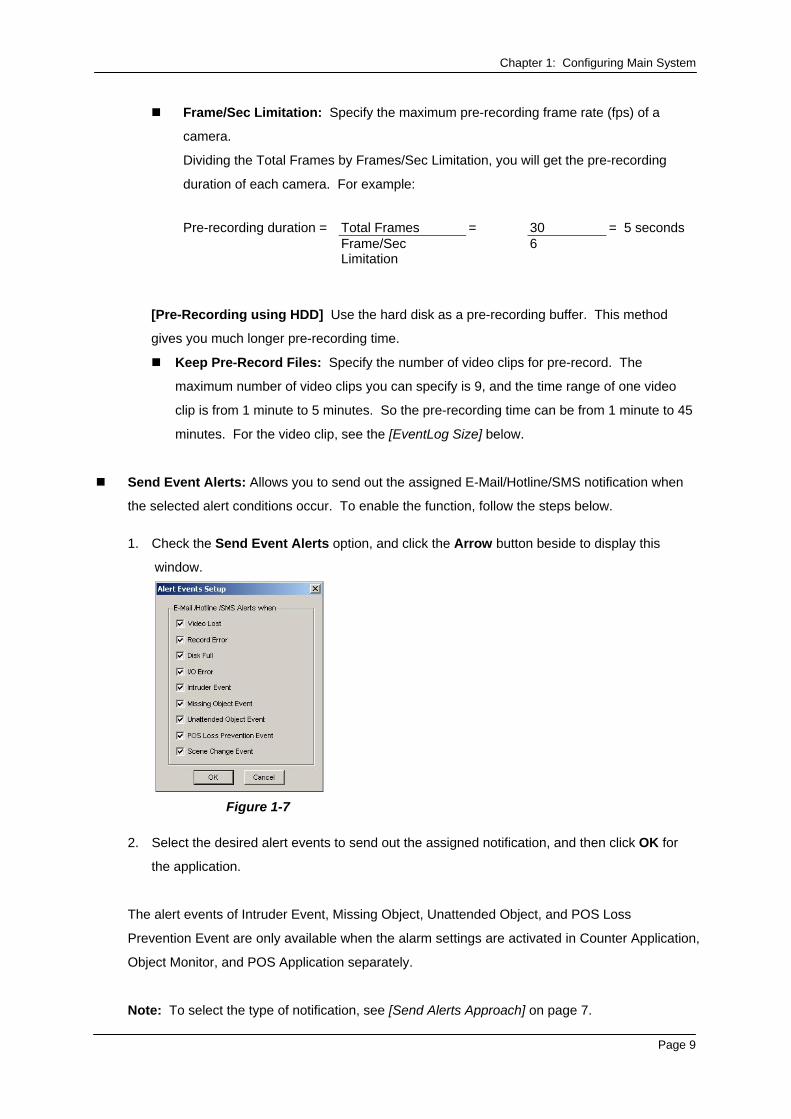
Send Event Alerts: Allows you to send out the assigned E-Mail/Hotline/SMS notification when
the selected alert conditions occur. To enable the function, follow the steps below.
1. Check the Send Event Alerts option, and click the Arrow button beside to display this
window.
Figure 1-7
2. Select the desired alert events to send out the assigned notification, and then click OK for
the application.
The alert events of Intruder Event, Missing Object, Unattended Object, and POS Loss
Prevention Event are only available when the alarm settings are activated in Counter Application,
Object Monitor, and POS Application separately.
Note: To select the type of notification, see [Send Alerts Approach] on page 7.
Page 9
Chapter 1: Configuring Main System [EventLog Size] Determines the amount of time (from 1 to 5 minutes) of each event file. If you
select 5 Min, a 30-minute event will be chopped into six 5-minute event files; if you select 1 Min, a 30-
minute event will be chopped into thirty 1-minute event files. To decide what to set up here, consider
how often you back up your event files, and how intensive the activity is in your surveillance area.
Smaller file size makes backup process faster.
[Camera Scan] Select to rotate through screen divisions. Click the drop-down list and specify the
amount of time that elapses before switching to the next screen division group. Press the Arrow
button to select the mode of screen divisions.
[Video Record] Click to watermark all recorded videos. Watermark is a way to verify the authenticity
of video streams, and to ensure that they have not been tampered with or modified in any way.
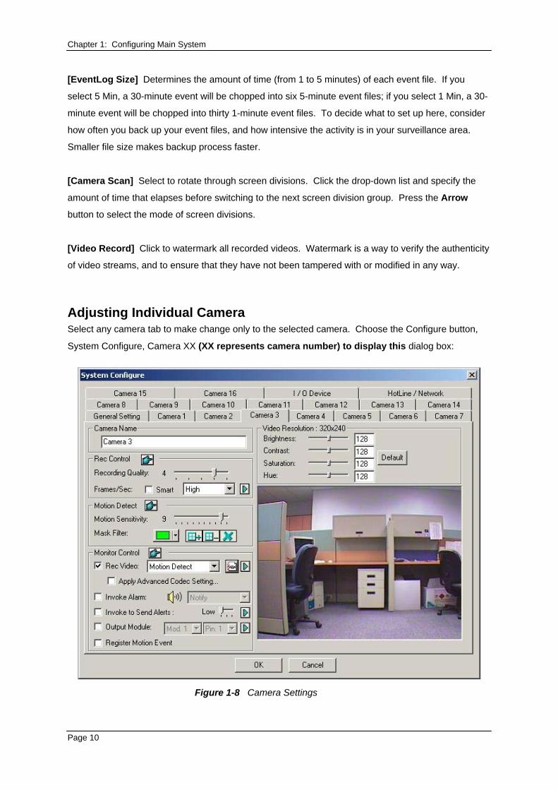
Adjusting Individual Camera Select any camera tab to make change only to the selected camera. Choose the Configure button,
System Configure, Camera XX (XX represents camera number) to display this dialog box:
Figure 1-8 Camera Settings
Page 10
Chapter 1: Configuring Main System Several settings could be configured here:
[Camera Name] The name entered here will appear in the upper-left hand corner of the camera
screen.
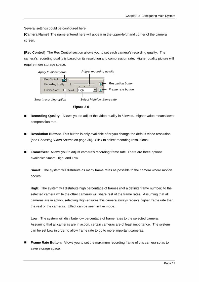
[Rec Control] The Rec Control section allows you to set each camera’s recording quality. The
camera’s recording quality is based on its resolution and compression rate. Higher quality picture will
require more storage space.
Apply to all cameras Adjust recording quality
Smart recording option Select high/low frame rate
Resolution button
Frame rate button
Figure 1-9
Recording Quality: Allows you to adjust the video quality in 5 levels. Higher value means lower
compression rate.
Resolution Button: This button is only available after you change the default video resolution
(see Choosing Video Source on page 30). Click to select recording resolutions.
Frame/Sec: Allows you to adjust camera’s recording frame rate. There are three options
available: Smart, High, and Low.
Smart: The system will distribute as many frame rates as possible to the camera where motion
occurs.
High: The system will distribute high percentage of frames (not a definite frame number) to the
selected camera while the other cameras will share rest of the frame rates. Assuming that all
cameras are in action, selecting High ensures this camera always receive higher frame rate than
the rest of the cameras. Effect can be seen in live mode.
Low: The system will distribute low percentage of frame rates to the selected camera.
Assuming that all cameras are in action, certain cameras are of least importance. The system
can be set Low in order to allow frame rate to go to more important cameras.
Frame Rate Button: Allows you to set the maximum recording frame of this camera so as to
save storage space.
Page 11
Chapter 1: Configuring Main System
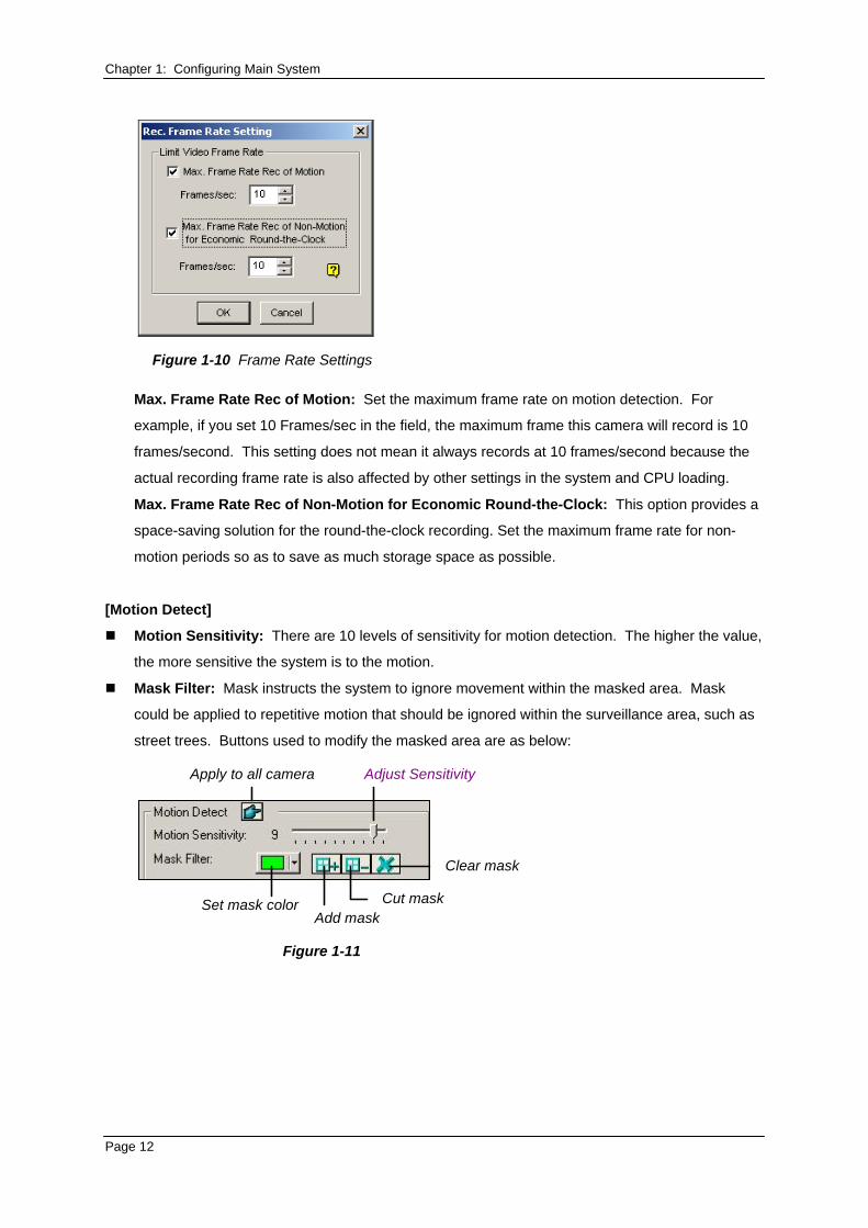
Figure 1-10 Frame Rate Settings
Max. Frame Rate Rec of Motion: Set the maximum frame rate on motion detection. For
example, if you set 10 Frames/sec in the field, the maximum frame this camera will record is 10
frames/second. This setting does not mean it always records at 10 frames/second because the
actual recording frame rate is also affected by other settings in the system and CPU loading.
Max. Frame Rate Rec of Non-Motion for Economic Round-the-Clock: This option provides a
space-saving solution for the round-the-clock recording. Set the maximum frame rate for non-
motion periods so as to save as much storage space as possible.
[Motion Detect]
Motion Sensitivity: There are 10 levels of sensitivity for motion detection. The higher the value,
the more sensitive the system is to the motion.
Mask Filter: Mask instructs the system to ignore movement within the masked area. Mask
could be applied to repetitive motion that should be ignored within the surveillance area, such as
street trees. Buttons used to modify the masked area are as below:
Apply to all camera Adjust Sensitivity
Set mask color
Clear mask
Cut maskAdd mask
Figure 1-11
Page 12
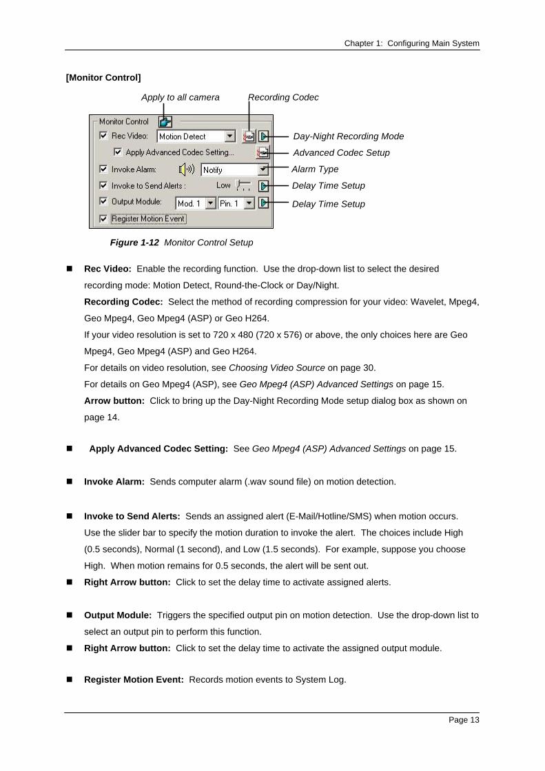
Chapter 1: Configuring Main System [Monitor Control]
Apply to all camera Recording Codec
Day-Night Recording Mode
Advanced Codec Setup
Alarm Type
Delay Time Setup
Delay Time Setup
Figure 1-12 Monitor Control Setup
Rec Video: Enable the recording function. Use the drop-down list to select the desired
recording mode: Motion Detect, Round-the-Clock or Day/Night.
Recording Codec: Select the method of recording compression for your video: Wavelet, Mpeg4,
Geo Mpeg4, Geo Mpeg4 (ASP) or Geo H264.
If your video resolution is set to 720 x 480 (720 x 576) or above, the only choices here are Geo
Mpeg4, Geo Mpeg4 (ASP) and Geo H264.
For details on video resolution, see Choosing Video Source on page 30.
For details on Geo Mpeg4 (ASP), see Geo Mpeg4 (ASP) Advanced Settings on page 15.
Arrow button: Click to bring up the Day-Night Recording Mode setup dialog box as shown on
page 14.
Apply Advanced Codec Setting: See Geo Mpeg4 (ASP) Advanced Settings on page 15.
Invoke Alarm: Sends computer alarm (.wav sound file) on motion detection.
Invoke to Send Alerts: Sends an assigned alert (E-Mail/Hotline/SMS) when motion occurs.
Use the slider bar to specify the motion duration to invoke the alert. The choices include High
(0.5 seconds), Normal (1 second), and Low (1.5 seconds). For example, suppose you choose
High. When motion remains for 0.5 seconds, the alert will be sent out.
Right Arrow button: Click to set the delay time to activate assigned alerts.
Output Module: Triggers the specified output pin on motion detection. Use the drop-down list to
select an output pin to perform this function.
Right Arrow button: Click to set the delay time to activate the assigned output module.
Register Motion Event: Records motion events to System Log.
Page 13
Chapter 1: Configuring Main System Note: The delay time functions in Invoke to Send Alerts and Output Module allow you time to
deactivate prior alert and output settings. To deactivate these settings, you may stop monitoring or
enable the assigned input module set at “Deactivate notification when selected pin ON" in Figure
2-9, in Chapter 2.
[Video Resolution] Allows you to adjust video characteristics such as brightness, contrast,
saturation, and hue.
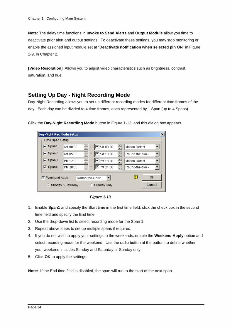
Setting Up Day - Night Recording Mode Day-Night Recording allows you to set up different recording modes for different time frames of the
day. Each day can be divided to 4 time frames, each represented by 1 Span (up to 4 Spans).
Click the Day-Night Recording Mode button in Figure 1-12, and this dialog box appears.
Figure 1-13
1. Enable Span1 and specify the Start time in the first time field; click the check box in the second
time field and specify the End time.
2. Use the drop-down list to select recording mode for the Span 1.
3. Repeat above steps to set up multiple spans if required.
4. If you do not wish to apply your settings to the weekends, enable the Weekend Apply option and
select recording mode for the weekend. Use the radio button at the bottom to define whether
your weekend includes Sunday and Saturday or Sunday only.
5. Click OK to apply the settings.
Note: If the End time field is disabled, the span will run to the start of the next span.
Page 14

Chapter 1: Configuring Main System Geo Mpeg4 (ASP) Advanced Settings The Geo Mpeg4 (ASP) codec supports a number of advanced settings that allow experienced users
to fine tune the encoding process.
In Figure 1-12, check the Apply Advanced Codec Setting option, and then click the button beside. This window appears.
Figure 1-14
[Setting]
Setting: Click the drop-down list to select High speed, Recommend, or High compression
rate for default configurations. Or, select User-defined to define encoding settings yourself.
Subpixel precision: Click the drop-down list to select Full, Half or Quarter pixel.
Full pixel: Fastest compression speed, medium compression rate, and normal image quality.
Half pixel: Fast compression speed, high compression rate, and better image quality.
Quarter pixel: Slow compression speed, highest compression rate, and better image quality.
Quantizer: Raising the value will improve compression speed and dramatically increase
compression rate, but reduce image quality.
Inter-frame threshold: Raising the value will improve compression speed and rate, but
reduce image quality slightly.
Page 15
Chapter 1: Configuring Main System Max. keyframe interval: Raising the value will extend the duration between key frames
and increase compression rate, but reduce image quality slightly. Compression speed remains
the same.
[Evaluation]
Encode size: Click to calculate the encoding size based on your encoding settings (see [Setting]
above) and assigned video clip (select PTZ dome or street from the drop-down list). Click the
Stop tab to stop the evaluation.
Encode speed: Click to calculate the frame rate based on the encoding settings (see [Setting]
above) and assigned video clip (select PTZ dome or street from the drop-down list).
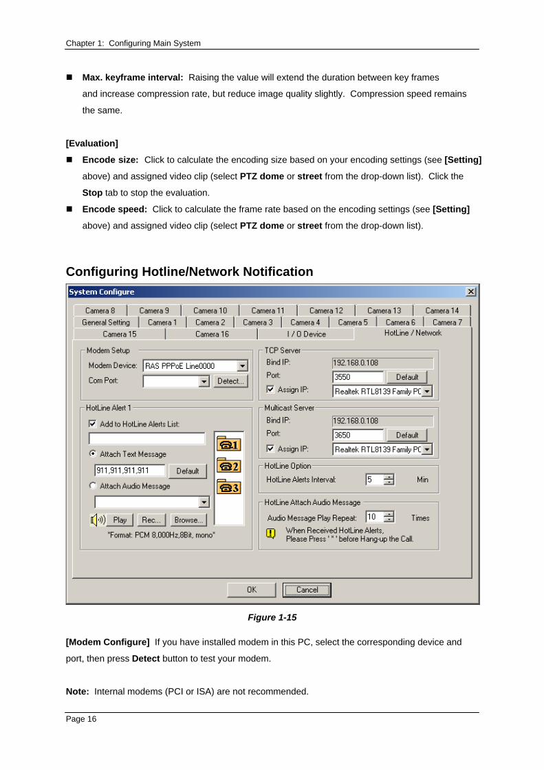
Configuring Hotline/Network Notification
Figure 1-15
[Modem Configure] If you have installed modem in this PC, select the corresponding device and
port, then press Detect button to test your modem.
Note: Internal modems (PCI or ISA) are not recommended.
Page 16
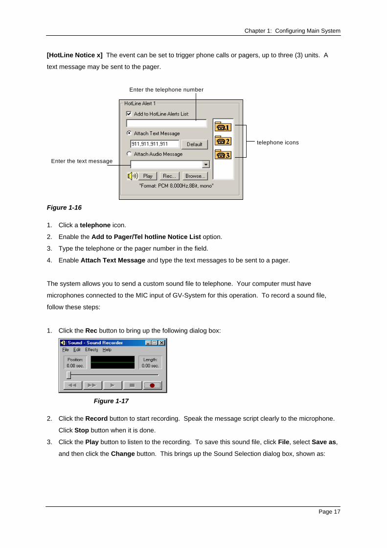
Chapter 1: Configuring Main System [HotLine Notice x] The event can be set to trigger phone calls or pagers, up to three (3) units. A
text message may be sent to the pager.
Enter the telephone number
telephone icons
Enter the text message
Figure 1-16
1. Click a telephone icon.
2. Enable the Add to Pager/Tel hotline Notice List option.
3. Type the telephone or the pager number in the field.
4. Enable Attach Text Message and type the text messages to be sent to a pager.
The system allows you to send a custom sound file to telephone. Your computer must have
microphones connected to the MIC input of GV-System for this operation. To record a sound file,
follow these steps:
1. Click the Rec button to bring up the following dialog box:
Figure 1-17
2. Click the Record button to start recording. Speak the message script clearly to the microphone.
Click Stop button when it is done.
3. Click the Play button to listen to the recording. To save this sound file, click File, select Save as,
and then click the Change button. This brings up the Sound Selection dialog box, shown as:
Page 17

Chapter 1: Configuring Main System
Figure 1-18
4. Select PCM 8,000 Hz, 8-bit Mono, the only format supported for this feature, and then click OK.
To find a sound file, click the Browse button to locate the file. Add the path of the file to the field, and
the file will be sent with the telephone calls.
[TCP Server] Allows you to setup TCP server. Enable Assign IP to enable the drop-down list.
Select the network card from drop-down list and your IP address will be displayed in Bind IP. The
default port number for TCP server is 3550; you may assign different port by entering the port number
in the Port field.
[Multicast Server] Allows you to setup the Multicast server; its operation is similar to the TCP server
setup described above. The default port number for Multicast server is 3650.
Note: GV-System automatically checks the dynamic IP of your PC every one minute. This ensures
connection of remote applications, including Remote View, IP Multicast, WebCam, and Remote
Playback.
[HotLine Option] If motion persists, decides how often, specified in minutes, the system should send
a notification to you before the motion ends.
[HotLine Attach Audio Message] Specifies how many times to repeat the audio message when a
telephone call is made to you.
Selecting Screen Layout This feature gives you the option of screen layout for the 8, 12 and 16 screen divisions.
1. Click the Configure button, and then select System Configure. The System Configure window
appears.
2. In the Startup section, click the Arrow button next to the Panel Resolution item to call up the
following window. The left mode is the default layout; the right is the enhanced layout.
Page 18
Chapter 1: Configuring Main System
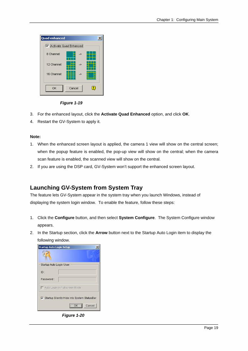
Figure 1-19
3. For the enhanced layout, click the Activate Quad Enhanced option, and click OK.
4. Restart the GV-System to apply it.
Note:
1. When the enhanced screen layout is applied, the camera 1 view will show on the central screen;
when the popup feature is enabled, the pop-up view will show on the central; when the camera
scan feature is enabled, the scanned view will show on the central.
2. If you are using the DSP card, GV-System won’t support the enhanced screen layout.
Launching GV-System from System Tray The feature lets GV-System appear in the system tray when you launch Windows, instead of
displaying the system login window. To enable the feature, follow these steps:
1. Click the Configure button, and then select System Configure. The System Configure window
appears.
2. In the Startup section, click the Arrow button next to the Startup Auto Login item to display the
following window.
Figure 1-20
Page 19
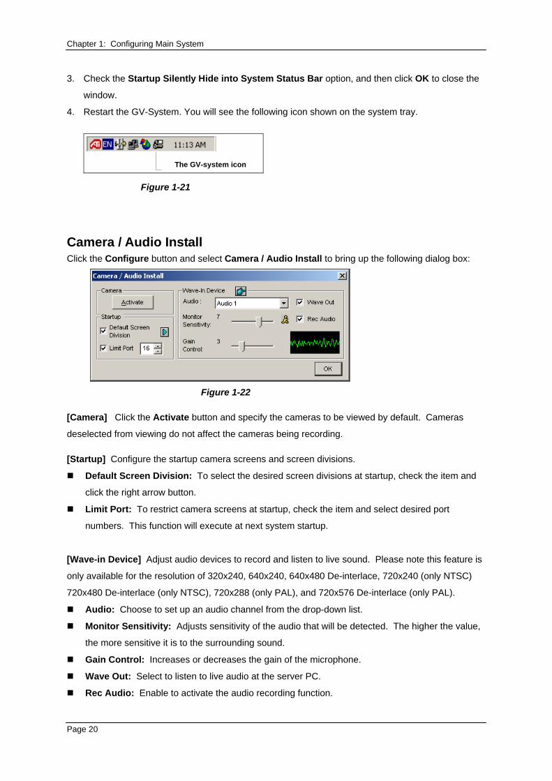
Chapter 1: Configuring Main System 3. Check the Startup Silently Hide into System Status Bar option, and then click OK to close the
window.
4. Restart the GV-System. You will see the following icon shown on the system tray.
The GV-system icon
Figure 1-21
Camera / Audio Install Click the Configure button and select Camera / Audio Install to bring up the following dialog box:
Figure 1-22
[Camera] Click the Activate button and specify the cameras to be viewed by default. Cameras
deselected from viewing do not affect the cameras being recording. [Startup] Configure the startup camera screens and screen divisions.
Default Screen Division: To select the desired screen divisions at startup, check the item and
click the right arrow button.
Limit Port: To restrict camera screens at startup, check the item and select desired port
numbers. This function will execute at next system startup.
[Wave-in Device] Adjust audio devices to record and listen to live sound. Please note this feature is
only available for the resolution of 320x240, 640x240, 640x480 De-interlace, 720x240 (only NTSC)
720x480 De-interlace (only NTSC), 720x288 (only PAL), and 720x576 De-interlace (only PAL).
Audio: Choose to set up an audio channel from the drop-down list.
Monitor Sensitivity: Adjusts sensitivity of the audio that will be detected. The higher the value,
the more sensitive it is to the surrounding sound.
Gain Control: Increases or decreases the gain of the microphone.
Wave Out: Select to listen to live audio at the server PC.
Rec Audio: Enable to activate the audio recording function.
Page 20
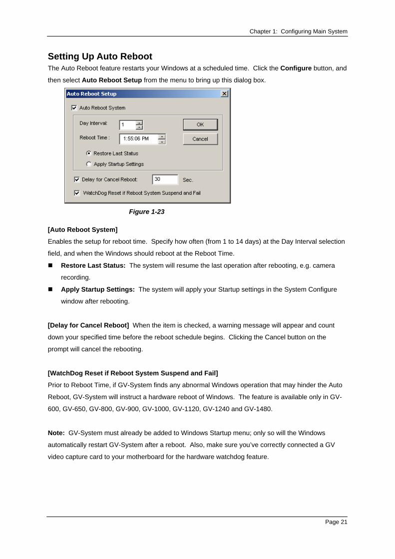
Chapter 1: Configuring Main System Setting Up Auto Reboot The Auto Reboot feature restarts your Windows at a scheduled time. Click the Configure button, and
then select Auto Reboot Setup from the menu to bring up this dialog box.
Figure 1-23
[Auto Reboot System]
Enables the setup for reboot time. Specify how often (from 1 to 14 days) at the Day Interval selection
field, and when the Windows should reboot at the Reboot Time.
Restore Last Status: The system will resume the last operation after rebooting, e.g. camera
recording.
Apply Startup Settings: The system will apply your Startup settings in the System Configure
window after rebooting.
[Delay for Cancel Reboot] When the item is checked, a warning message will appear and count
down your specified time before the reboot schedule begins. Clicking the Cancel button on the
prompt will cancel the rebooting.
[WatchDog Reset if Reboot System Suspend and Fail]
Prior to Reboot Time, if GV-System finds any abnormal Windows operation that may hinder the Auto
Reboot, GV-System will instruct a hardware reboot of Windows. The feature is available only in GV-
600, GV-650, GV-800, GV-900, GV-1000, GV-1120, GV-1240 and GV-1480.
Note: GV-System must already be added to Windows Startup menu; only so will the Windows
automatically restart GV-System after a reboot. Also, make sure you’ve correctly connected a GV
video capture card to your motherboard for the hardware watchdog feature.
Page 21
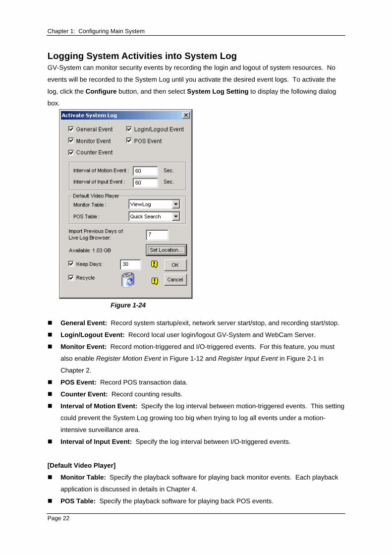
Chapter 1: Configuring Main System Logging System Activities into System Log GV-System can monitor security events by recording the login and logout of system resources. No
events will be recorded to the System Log until you activate the desired event logs. To activate the
log, click the Configure button, and then select System Log Setting to display the following dialog
box.
Figure 1-24
General Event: Record system startup/exit, network server start/stop, and recording start/stop.
Login/Logout Event: Record local user login/logout GV-System and WebCam Server.
Monitor Event: Record motion-triggered and I/O-triggered events. For this feature, you must
also enable Register Motion Event in Figure 1-12 and Register Input Event in Figure 2-1 in
Chapter 2.
POS Event: Record POS transaction data.
Counter Event: Record counting results.
Interval of Motion Event: Specify the log interval between motion-triggered events. This setting
could prevent the System Log growing too big when trying to log all events under a motion-
intensive surveillance area.
Interval of Input Event: Specify the log interval between I/O-triggered events.
[Default Video Player]
Monitor Table: Specify the playback software for playing back monitor events. Each playback
application is discussed in details in Chapter 4.
POS Table: Specify the playback software for playing back POS events.
Page 22
Chapter 1: Configuring Main System [Import Previous Days of Live Log Browser] Specify how many days of data to be loaded to the
System Log.
Set Location: Click the Set Location button to specify a storage path. The available free space
will be displayed in left hand side.
Keep Days: Set the number of days to keep log files.
Recycle: Enable the system to delete old log files to make space for new files when HDD free
space is below 500MB.
To view and learn more about System Log, see page 35.
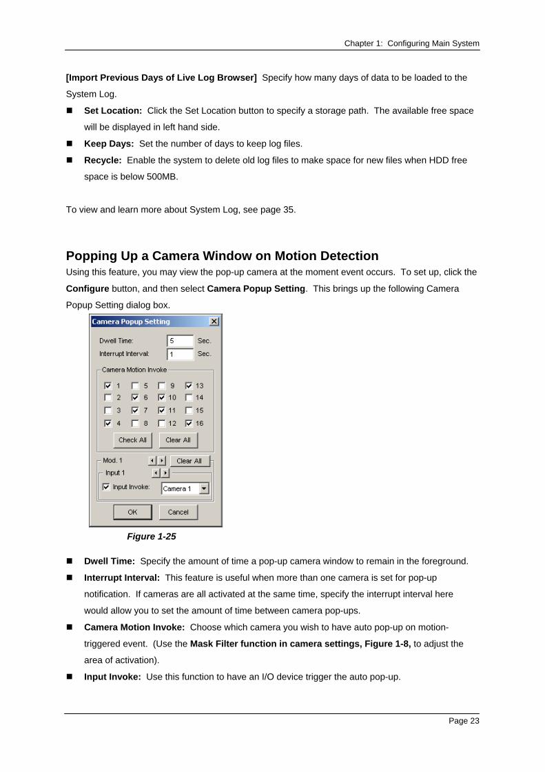
Popping Up a Camera Window on Motion Detection Using this feature, you may view the pop-up camera at the moment event occurs. To set up, click the
Configure button, and then select Camera Popup Setting. This brings up the following Camera
Popup Setting dialog box.
Figure 1-25
Dwell Time: Specify the amount of time a pop-up camera window to remain in the foreground.
Interrupt Interval: This feature is useful when more than one camera is set for pop-up
notification. If cameras are all activated at the same time, specify the interrupt interval here
would allow you to set the amount of time between camera pop-ups.
Camera Motion Invoke: Choose which camera you wish to have auto pop-up on motion-
triggered event. (Use the Mask Filter function in camera settings, Figure 1-8, to adjust the
area of activation).
Input Invoke: Use this function to have an I/O device trigger the auto pop-up.
Page 23
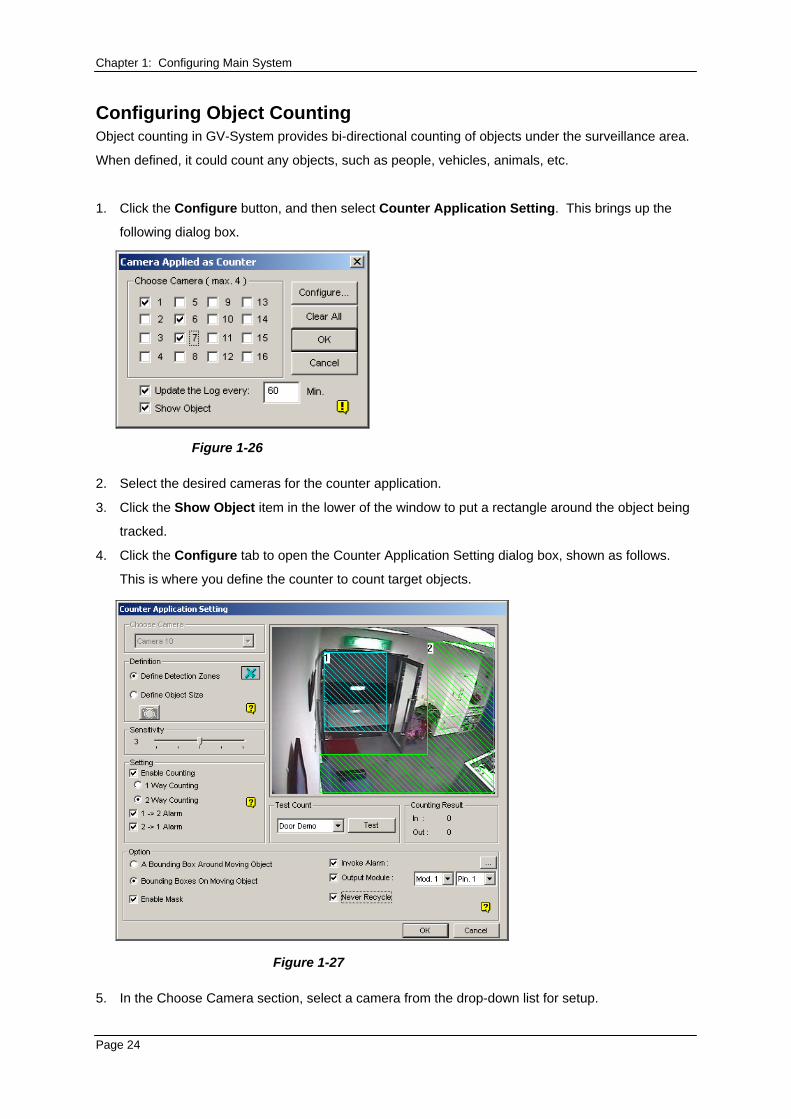
Chapter 1: Configuring Main System Configuring Object Counting Object counting in GV-System provides bi-directional counting of objects under the surveillance area.
When defined, it could count any objects, such as people, vehicles, animals, etc.
1. Click the Configure button, and then select Counter Application Setting. This brings up the
following dialog box.
Figure 1-26
2. Select the desired cameras for the counter application.
3. Click the Show Object item in the lower of the window to put a rectangle around the object being
tracked.
4. Click the Configure tab to open the Counter Application Setting dialog box, shown as follows.
This is where you define the counter to count target objects.
Figure 1-27
5. In the Choose Camera section, select a camera from the drop-down list for setup.
Page 24
Chapter 1: Configuring Main System 6. In the Definition section, there are two options:
Set Detection Zones: Use the mouse to outline detection regions on the video image.
Number 1 is for region 1; number 2 for region 2. Defining multiple regions 1 and 2 is
practicable. Clicking the delete (blue X icon) button will clear all defined regions.
Define Object Sizes: Use the mouse to outline a region matching the normal size of the
targeted object. If the video is playing, first click the Snapshot button to freeze the image
before defining.
7. In the Setting section, the three options represent:
Enable Counting:
1 Way Counting: When an object appears in region 1 and then enters into region 2, it will be
counted as 1 in.
2 Way Counting: When an object appears in region 1 and then enters into region 2, it will
be counted as 1 in, and when an object appears in region 2 and then enters region 1 it will be
counted as 1 out.
1→2 Alarm: When an object enters from region 1 to region 2, the event will be recorded as
“Intruder” in System Log for later retrieval.
2→1 Alarm: When an object enters from the defined region 2 to region 1, the event will be
recorded as “Intruder” in System Log for later retrieval.
8. In the Option section, select how you want to highlight the detected object. If Enable Mask is
enabled, masks will be displayed on the detection regions.
9. If the alarm settings in step 7 are selected, the following options will be enabled:
Invoke Alarm: Activate the computer noise alarm when an object enters a defined region.
Click the button next to the item to assign a wav sound file.
Output Module: Enable an installed output device when an object enters a defined region.
Assign the output module and pin number.
Never Recycle: When the item is checked, the alarm-triggered events won’t be recycled
even when disk space is full.
10. To test your settings of counting, select Live from the drop-down list, and then click the Test
button. Notice how the number changes in the Counting Result section when objects pass
through the detection regions. There are three options in the drop-down list. Live tests your
current settings; Door Demo and Traffic Demo are pre-recorded events, showing how the
application counts objects in two actual DVR examples.
Page 25
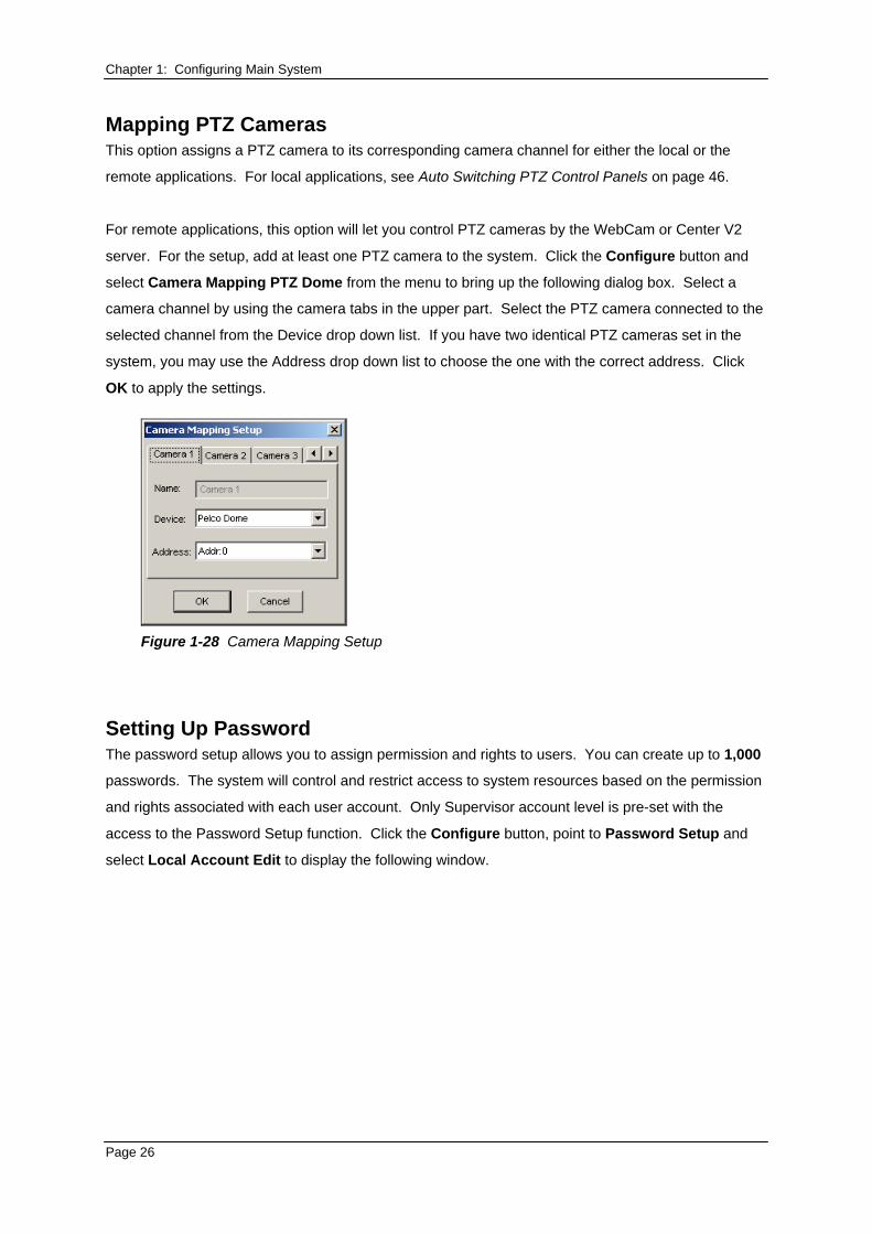
Chapter 1: Configuring Main System Mapping PTZ Cameras This option assigns a PTZ camera to its corresponding camera channel for either the local or the
remote applications. For local applications, see Auto Switching PTZ Control Panels on page 46.
For remote applications, this option will let you control PTZ cameras by the WebCam or Center V2
server. For the setup, add at least one PTZ camera to the system. Click the Configure button and
select Camera Mapping PTZ Dome from the menu to bring up the following dialog box. Select a
camera channel by using the camera tabs in the upper part. Select the PTZ camera connected to the
selected channel from the Device drop down list. If you have two identical PTZ cameras set in the
system, you may use the Address drop down list to choose the one with the correct address. Click
OK to apply the settings.
Figure 1-28 Camera Mapping Setup
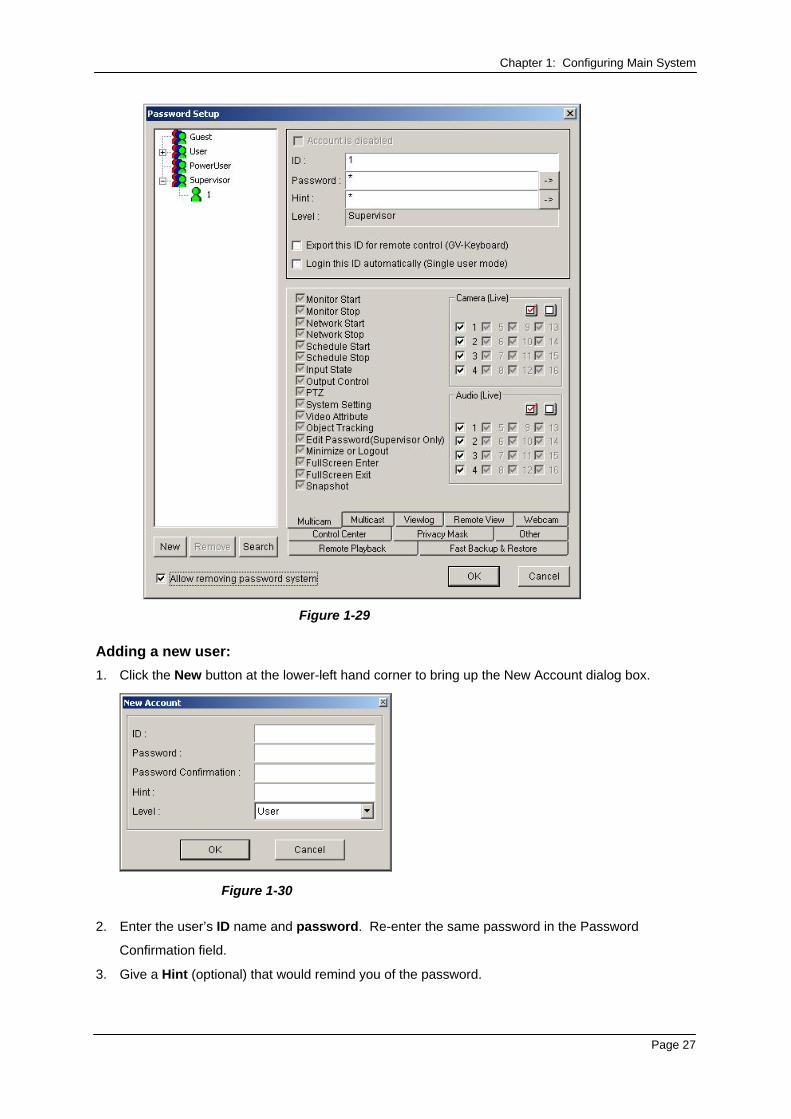
Setting Up Password The password setup allows you to assign permission and rights to users. You can create up to 1,000
passwords. The system will control and restrict access to system resources based on the permission
and rights associated with each user account. Only Supervisor account level is pre-set with the
access to the Password Setup function. Click the Configure button, point to Password Setup and
select Local Account Edit to display the following window.
Page 26
Chapter 1: Configuring Main System
Figure 1-29
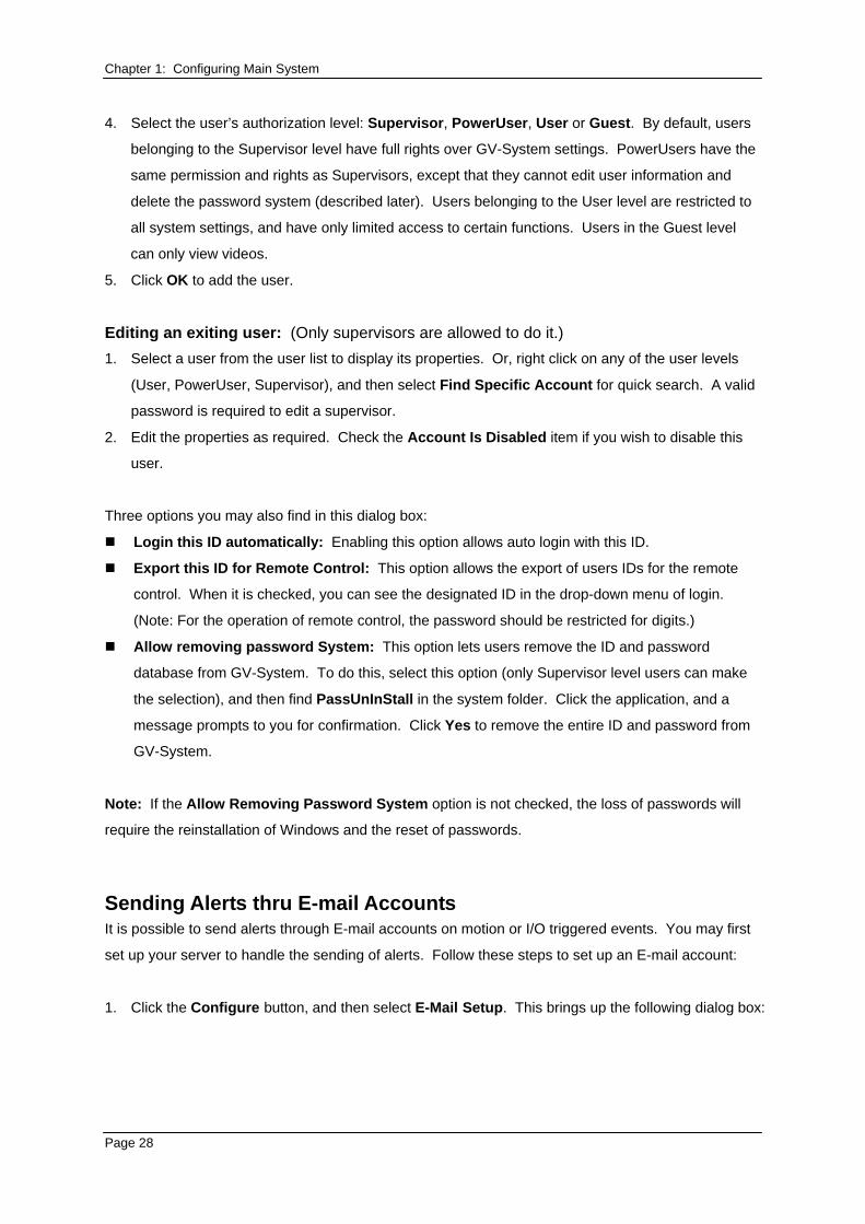
Adding a new user: 1. Click the New button at the lower-left hand corner to bring up the New Account dialog box.
Figure 1-30
2. Enter the user’s ID name and password. Re-enter the same password in the Password
Confirmation field.
3. Give a Hint (optional) that would remind you of the password.
Page 27
Chapter 1: Configuring Main System 4. Select the user’s authorization level: Supervisor, PowerUser, User or Guest. By default, users
belonging to the Supervisor level have full rights over GV-System settings. PowerUsers have the
same permission and rights as Supervisors, except that they cannot edit user information and
delete the password system (described later). Users belonging to the User level are restricted to
all system settings, and have only limited access to certain functions. Users in the Guest level
can only view videos.
5. Click OK to add the user.
Editing an exiting user: (Only supervisors are allowed to do it.) 1. Select a user from the user list to display its properties. Or, right click on any of the user levels
(User, PowerUser, Supervisor), and then select Find Specific Account for quick search. A valid
password is required to edit a supervisor.
2. Edit the properties as required. Check the Account Is Disabled item if you wish to disable this
user.
Three options you may also find in this dialog box:
Login this ID automatically: Enabling this option allows auto login with this ID.
Export this ID for Remote Control: This option allows the export of users IDs for the remote
control. When it is checked, you can see the designated ID in the drop-down menu of login.
(Note: For the operation of remote control, the password should be restricted for digits.)
Allow removing password System: This option lets users remove the ID and password
database from GV-System. To do this, select this option (only Supervisor level users can make
the selection), and then find PassUnInStall in the system folder. Click the application, and a
message prompts to you for confirmation. Click Yes to remove the entire ID and password from
GV-System.
Note: If the Allow Removing Password System option is not checked, the loss of passwords will
require the reinstallation of Windows and the reset of passwords.
Sending Alerts thru E-mail Accounts It is possible to send alerts through E-mail accounts on motion or I/O triggered events. You may first
set up your server to handle the sending of alerts. Follow these steps to set up an E-mail account:
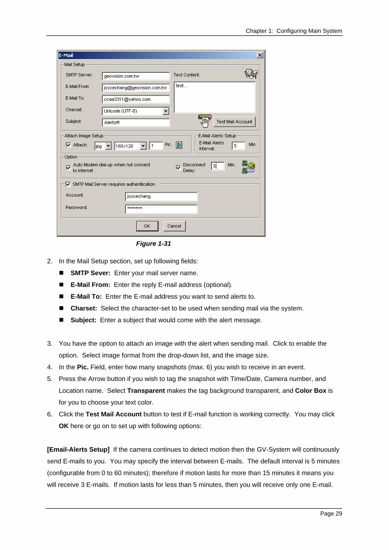
1. Click the Configure button, and then select E-Mail Setup. This brings up the following dialog box:
Page 28
Chapter 1: Configuring Main System
Figure 1-31
2. In the Mail Setup section, set up following fields:
SMTP Sever: Enter your mail server name.
E-Mail From: Enter the reply E-mail address (optional).
E-Mail To: Enter the E-mail address you want to send alerts to.
Charset: Select the character-set to be used when sending mail via the system.
Subject: Enter a subject that would come with the alert message.
3. You have the option to attach an image with the alert when sending mail. Click to enable the
option. Select image format from the drop-down list, and the image size.
4. In the Pic. Field, enter how many snapshots (max. 6) you wish to receive in an event.
5. Press the Arrow button if you wish to tag the snapshot with Time/Date, Camera number, and
Location name. Select Transparent makes the tag background transparent, and Color Box is
for you to choose your text color.
6. Click the Test Mail Account button to test if E-mail function is working correctly. You may click
OK here or go on to set up with following options:
[Email-Alerts Setup] If the camera continues to detect motion then the GV-System will continuously
send E-mails to you. You may specify the interval between E-mails. The default interval is 5 minutes
(configurable from 0 to 60 minutes); therefore if motion lasts for more than 15 minutes it means you
will receive 3 E-mails. If motion lasts for less than 5 minutes, then you will receive only one E-mail.
Page 29
Chapter 1: Configuring Main System [Option] Select Auto Modem dial-up to dial-up automatically when the system is instructed to send
E-mail alerts. The Disconnect Delay disconnects the system from Internet after the set number of
minute(s) (from 0 to 30 minutes).
[SMTP Mail Server requires authentication] If the SMTP mail server needs authentication, select
this item and enter your account name and password.
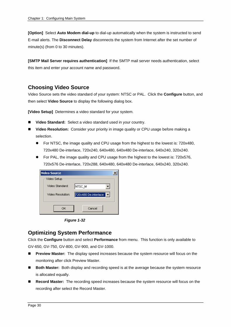
Choosing Video Source Video Source sets the video standard of your system: NTSC or PAL. Click the Configure button, and
then select Video Source to display the following dialog box.
[Video Setup] Determines a video standard for your system.
Video Standard: Select a video standard used in your country.
Video Resolution: Consider your priority in image quality or CPU usage before making a
selection.
For NTSC, the image quality and CPU usage from the highest to the lowest is: 720x480,
720x480 De-interlace, 720x240, 640x480, 640x480 De-interlace, 640x240, 320x240.
For PAL, the image quality and CPU usage from the highest to the lowest is: 720x576,
720x576 De-interlace, 720x288, 640x480, 640x480 De-interlace, 640x240, 320x240.
Figure 1-32
Optimizing System Performance Click the Configure button and select Performance from menu. This function is only available to
GV-650, GV-750, GV-800, GV-900, and GV-1000.
Preview Master: The display speed increases because the system resource will focus on the
monitoring after click Preview Master.
Both Master: Both display and recording speed is at the average because the system resource
is allocated equally.
Record Master: The recording speed increases because the system resource will focus on the
recording after select the Record Master.
Page 30
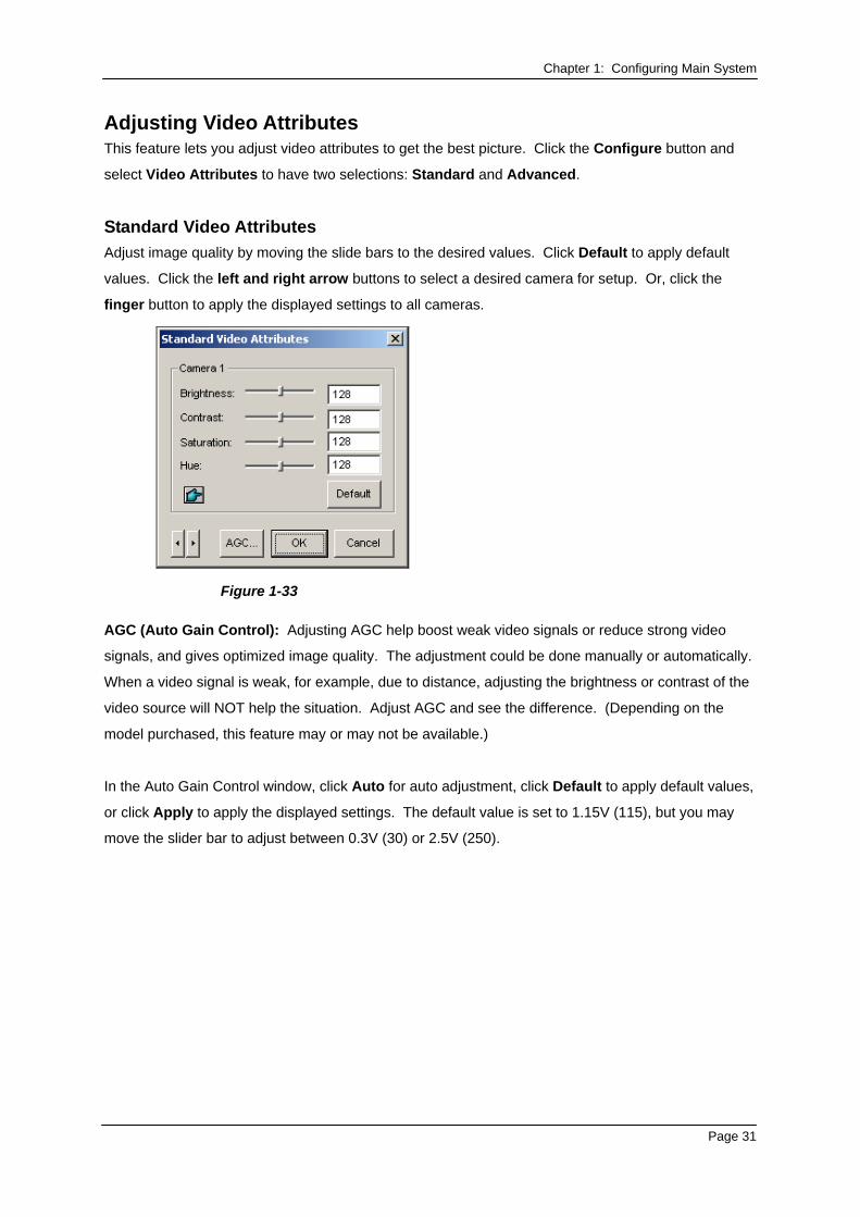
Chapter 1: Configuring Main System Adjusting Video Attributes This feature lets you adjust video attributes to get the best picture. Click the Configure button and
select Video Attributes to have two selections: Standard and Advanced.
Standard Video Attributes Adjust image quality by moving the slide bars to the desired values. Click Default to apply default
values. Click the left and right arrow buttons to select a desired camera for setup. Or, click the
finger button to apply the displayed settings to all cameras.
Figure 1-33
AGC (Auto Gain Control): Adjusting AGC help boost weak video signals or reduce strong video
signals, and gives optimized image quality. The adjustment could be done manually or automatically.
When a video signal is weak, for example, due to distance, adjusting the brightness or contrast of the
video source will NOT help the situation. Adjust AGC and see the difference. (Depending on the
model purchased, this feature may or may not be available.)
In the Auto Gain Control window, click Auto for auto adjustment, click Default to apply default values,
or click Apply to apply the displayed settings. The default value is set to 1.15V (115), but you may
move the slider bar to adjust between 0.3V (30) or 2.5V (250).
Page 31
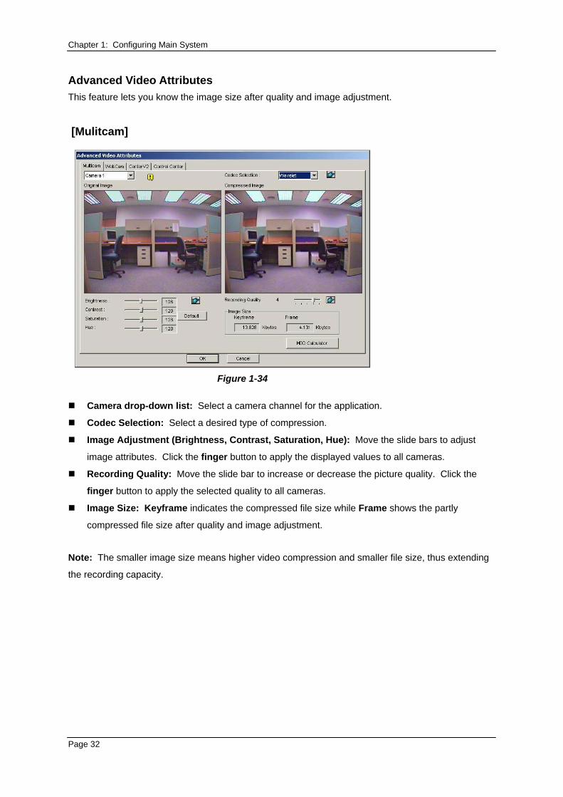
Chapter 1: Configuring Main System Advanced Video Attributes This feature lets you know the image size after quality and image adjustment.
[Mulitcam]
Figure 1-34
Camera drop-down list: Select a camera channel for the application.
Codec Selection: Select a desired type of compression.
Image Adjustment (Brightness, Contrast, Saturation, Hue): Move the slide bars to adjust
image attributes. Click the finger button to apply the displayed values to all cameras.
Recording Quality: Move the slide bar to increase or decrease the picture quality. Click the
finger button to apply the selected quality to all cameras.
Image Size: Keyframe indicates the compressed file size while Frame shows the partly
compressed file size after quality and image adjustment.
Note: The smaller image size means higher video compression and smaller file size, thus extending
the recording capacity.
Page 32
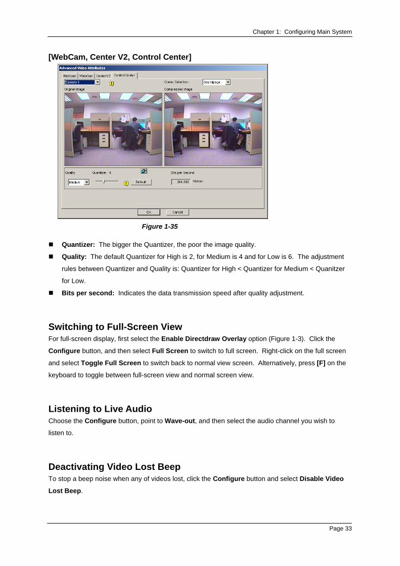
Chapter 1: Configuring Main System [WebCam, Center V2, Control Center]
Figure 1-35
Quantizer: The bigger the Quantizer, the poor the image quality.
Quality: The default Quantizer for High is 2, for Medium is 4 and for Low is 6. The adjustment
rules between Quantizer and Quality is: Quantizer for High < Quantizer for Medium < Quanitzer
for Low.
Bits per second: Indicates the data transmission speed after quality adjustment.
Switching to Full-Screen View For full-screen display, first select the Enable Directdraw Overlay option (Figure 1-3). Click the
Configure button, and then select Full Screen to switch to full screen. Right-click on the full screen
and select Toggle Full Screen to switch back to normal view screen. Alternatively, press [F] on the
keyboard to toggle between full-screen view and normal screen view.
Listening to Live Audio Choose the Configure button, point to Wave-out, and then select the audio channel you wish to
listen to.
Deactivating Video Lost Beep To stop a beep noise when any of videos lost, click the Configure button and select Disable Video
Lost Beep.
Page 33
Chapter 1: Configuring Main System
Start/Stop Monitoring
Select the Monitor button and select to start or stop all or individual camera monitoring. Camera
Name at the upper left corner of the view screen changes from yellow to red color when motion
detected. (Blinking represents the camera is detecting motion). [F7] is the shortcut key of this
operation.
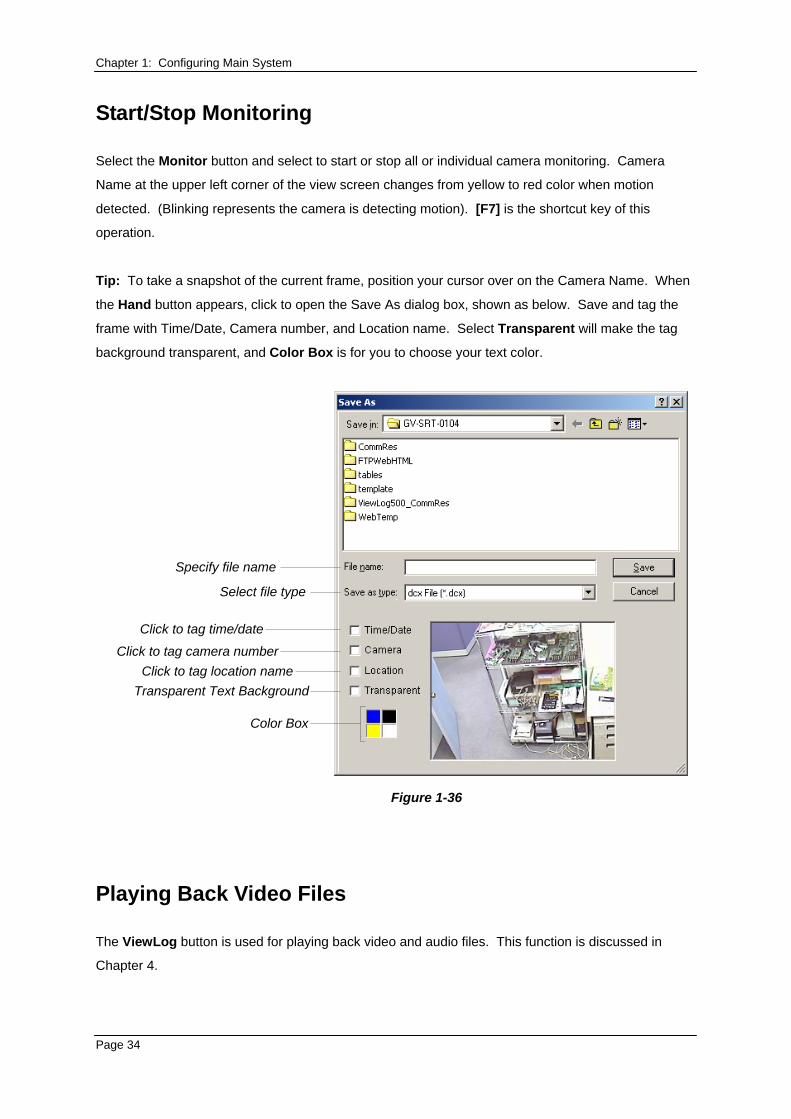
Tip: To take a snapshot of the current frame, position your cursor over on the Camera Name. When
the Hand button appears, click to open the Save As dialog box, shown as below. Save and tag the
frame with Time/Date, Camera number, and Location name. Select Transparent will make the tag
background transparent, and Color Box is for you to choose your text color.
Specify file name
Select file type
Click to tag time/dateClick to tag camera number
Click to tag location nameTransparent Text Background
Color Box
Figure 1-36
Playing Back Video Files
The ViewLog button is used for playing back video and audio files. This function is discussed in
Chapter 4.
Page 34
Chapter 1: Configuring Main System Instant Playback You can instantly open ViewLog to trace the event(s) of a certain time length without interrupting the
morning.
To instantly play back the event(s) of one single channel, click on the Camera Name, and then
select the time length.
To instantly play back the events of all channels, click on the ViewLog button, select Instant
Play, and then select the time length.
Time length choices include 10 seconds, 30 seconds, 1 minute and 5 minutes.
System Log
System Log displays detailed information about the GV-System and remote operation. This
information is being saved in a database Access format for this can be a useful tool to Supervisor. To
view the System Log, Click the ViewLog button, and then select System Log from the menu. This
brings up the Live Log Brower viewer as shown below. The Log Browser viewer displays five type of
event information. Use the control tab to switch between them. Click the […] icon on the upper right
corner to bring up Advanced Log Browser screen.
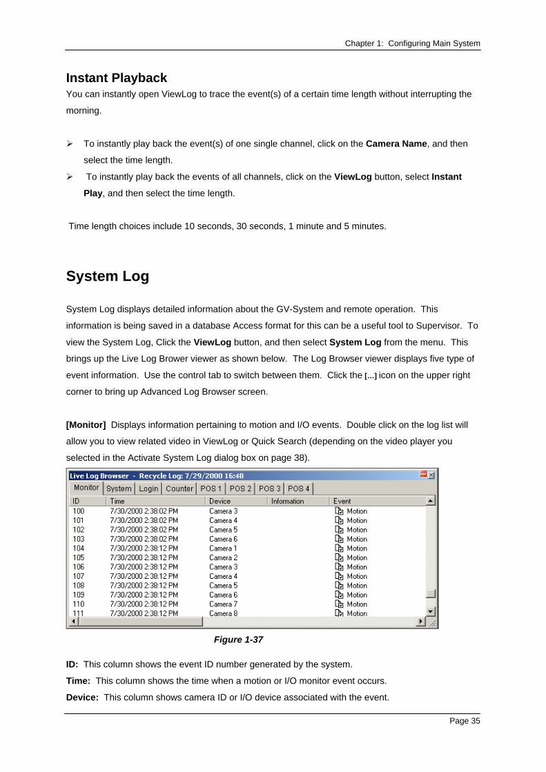
[Monitor] Displays information pertaining to motion and I/O events. Double click on the log list will
allow you to view related video in ViewLog or Quick Search (depending on the video player you
selected in the Activate System Log dialog box on page 38).
Figure 1-37
ID: This column shows the event ID number generated by the system.
Time: This column shows the time when a motion or I/O monitor event occurs.
Device: This column shows camera ID or I/O device associated with the event.
Page 35
Chapter 1: Configuring Main System Information: This column shows the I/O module number
Event: These event messages mean:
Motion: Appear if motion occurs in the associated camera.
Monitor Video Lost: Appear if video lost occurs in the associated camera.
Monitor Video Resume: Appear if video resume in the associated camera.
Signal On: Appear if one of the input device connected to the associated I/O module are
activated.
Signal Off: Appear if one of the input device connected to the associated I/O module are
terminated.
I/O error: Appear if associated I/O module failed.
I/O resume: Appear if associated I/O module resume to action.
Missing Object: Appear if objects miss from a defined camera view.
Unattended Object: Appear if unattended objects show up within a defined camera view.
Intruder: Appear if there are objects entering a defined region.
Disk Full: Appear if storage space is full.
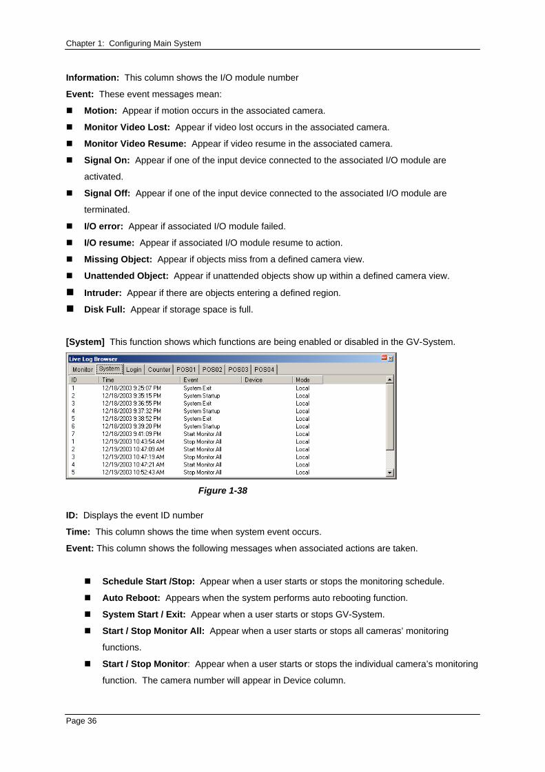
[System] This function shows which functions are being enabled or disabled in the GV-System.
Figure 1-38
ID: Displays the event ID number
Time: This column shows the time when system event occurs.
Event: This column shows the following messages when associated actions are taken.
Schedule Start /Stop: Appear when a user starts or stops the monitoring schedule.
Auto Reboot: Appears when the system performs auto rebooting function.
System Start / Exit: Appear when a user starts or stops GV-System.
Start / Stop Monitor All: Appear when a user starts or stops all cameras’ monitoring
functions.
Start / Stop Monitor: Appear when a user starts or stops the individual camera’s monitoring
function. The camera number will appear in Device column.
Page 36
Chapter 1: Configuring Main System
IO Monitor Start / Stop: Appear when a user starts or stops the individual I/O module’s
monitoring function. The I/O module number will appear in the Device column.
Modem Svr Start / Stop: Appear when a user starts or stops GV-System’s Modem Server.
TCP Svr Start / Stop: Appear when a user starts or stops GV-System’s TCP Server.
Multicast Svr Start / Stop: Appear when a user starts or stops Multicast Server.
WebCam Svr Start / Stop: Appear when a user starts or stops WebCam Server.
Connect to Center Start/ Stop: Appear when GV-System connects or disconnects with the
Security Center.
Twin Svr Start / Stop: Appear when a user starts or stops Twin Server.
Connect to Center V2 Start / Stop: Appear when GV-System logs in or out Center V2.
Connect to VSM Start/Stop/Net Down/ Net Resume: Appear when GV-System logs in or
out VSM; when the connection of both fails or resumes.
Connect to SMS Start/Stop/Net Down/Net Resume: Appear when GV-System logs in or
out the SMS server; when the connection of both fails or resumes.
Device: This column shows the individual camera number.
Mode: This column shows whether actions are being taken in local side or remote side.
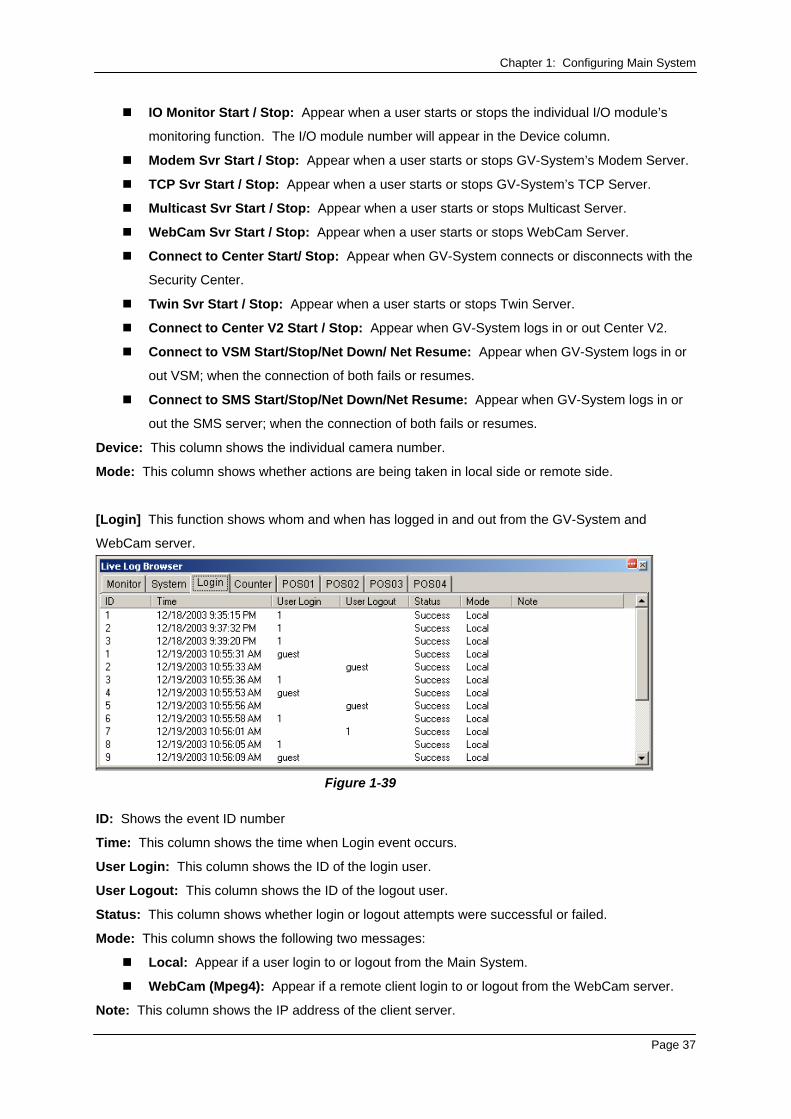
[Login] This function shows whom and when has logged in and out from the GV-System and
WebCam server.
Figure 1-39
ID: Shows the event ID number
Time: This column shows the time when Login event occurs.
User Login: This column shows the ID of the login user.
User Logout: This column shows the ID of the logout user.
Status: This column shows whether login or logout attempts were successful or failed.
Mode: This column shows the following two messages:
Local: Appear if a user login to or logout from the Main System.
WebCam (Mpeg4): Appear if a remote client login to or logout from the WebCam server.
Note: This column shows the IP address of the client server.
Page 37
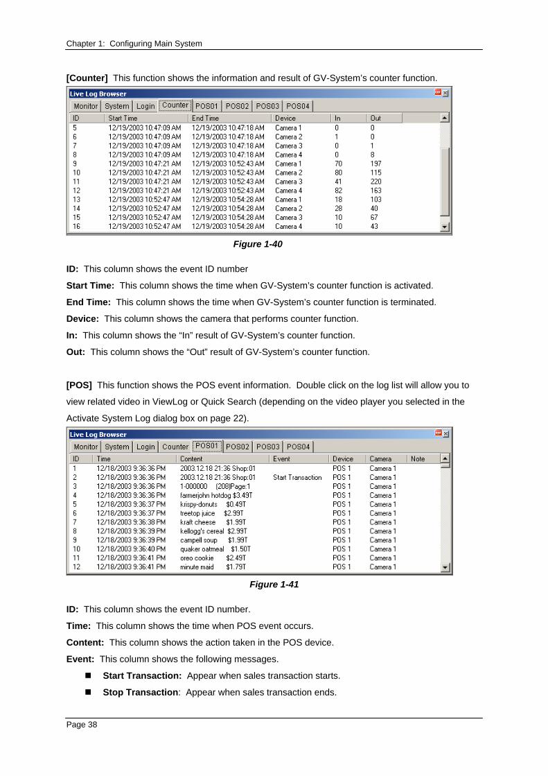
Chapter 1: Configuring Main System [Counter] This function shows the information and result of GV-System’s counter function.
Figure 1-40
ID: This column shows the event ID number
Start Time: This column shows the time when GV-System’s counter function is activated.
End Time: This column shows the time when GV-System’s counter function is terminated.
Device: This column shows the camera that performs counter function.
In: This column shows the “In” result of GV-System’s counter function.
Out: This column shows the “Out” result of GV-System’s counter function.
[POS] This function shows the POS event information. Double click on the log list will allow you to
view related video in ViewLog or Quick Search (depending on the video player you selected in the
Activate System Log dialog box on page 22).
Figure 1-41
ID: This column shows the event ID number.
Time: This column shows the time when POS event occurs.
Content: This column shows the action taken in the POS device.
Event: This column shows the following messages.
Start Transaction: Appear when sales transaction starts.
Stop Transaction: Appear when sales transaction ends.
Page 38
Chapter 1: Configuring Main System
Void Transaction: Appear if an item is being void from the sales transaction.
Cash Drawer Open: Appear if the cash drawer is opened.
Filter 1-15: Appear if the sales transaction matches the defined condition 1 to 15.
Note: This column is currently not being used.
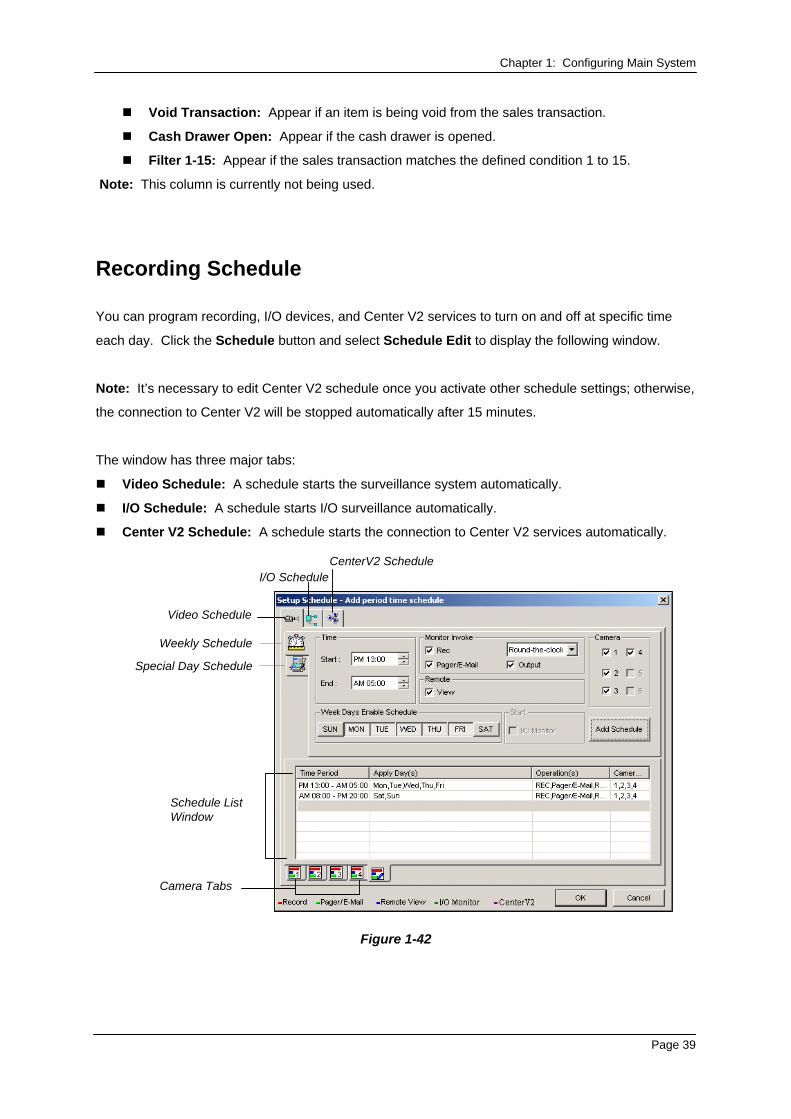
Recording Schedule
You can program recording, I/O devices, and Center V2 services to turn on and off at specific time
each day. Click the Schedule button and select Schedule Edit to display the following window.
Note: It’s necessary to edit Center V2 schedule once you activate other schedule settings; otherwise,
the connection to Center V2 will be stopped automatically after 15 minutes.
The window has three major tabs:
Video Schedule: A schedule starts the surveillance system automatically.
I/O Schedule: A schedule starts I/O surveillance automatically.
Center V2 Schedule: A schedule starts the connection to Center V2 services automatically.
Weekly Schedule
Special Day Schedule
I/O Schedule
Camera Tabs
Schedule List Window
CenterV2 Schedule
Video Schedule
Figure 1-42
Page 39
Chapter 1: Configuring Main System
Video Schedule 1. Set your surveillance preferences:
[Time] Enter the starting and ending time of the schedule.
[Monitor Invoke] Sets alert methods on motion detection.
Rec: Records while monitoring. From the drop-down list, select to record video by Motion
Detect or Round-the-Clock.
Pager/E-Mail: Sends pager or e-mail alerts on motion detection.
Output: Triggers the corresponding I/O devices on motion detection. To set up I/O devices,
see Adjusting Individual Camera on page 10.
[Remote] Sends the triggered images to the remote applications (WebCam, MultiView or
RemoteView).
[Week Days Enable Schedule] Select days for the schedule.
[Start] Only enabled in I/O Schedule.
[Camera] Applies the settings to selected cameras.
2. Click the Add Schedule tab to apply above settings. The set schedule will display on the
Schedule List Window.
3. Repeat above steps to set up more schedules.
Clicking separate Camera tabs, you will see the set schedule is displayed in different color bars:
Red: Recording enabled
Green: Pager/E-mail notification enabled
Blue: System will send videos to Remote View
Jade: I/O monitor enabled
Purple: Center V2 schedule enabled.
To modify a schedule, highlight the desired schedule in the Schedule List window, and then press the
Modify Schedule button to make changes.
To delete a schedule, highlight the desired schedule in the Schedule List window, and the press the
Delete key on the keyboard.
Page 40
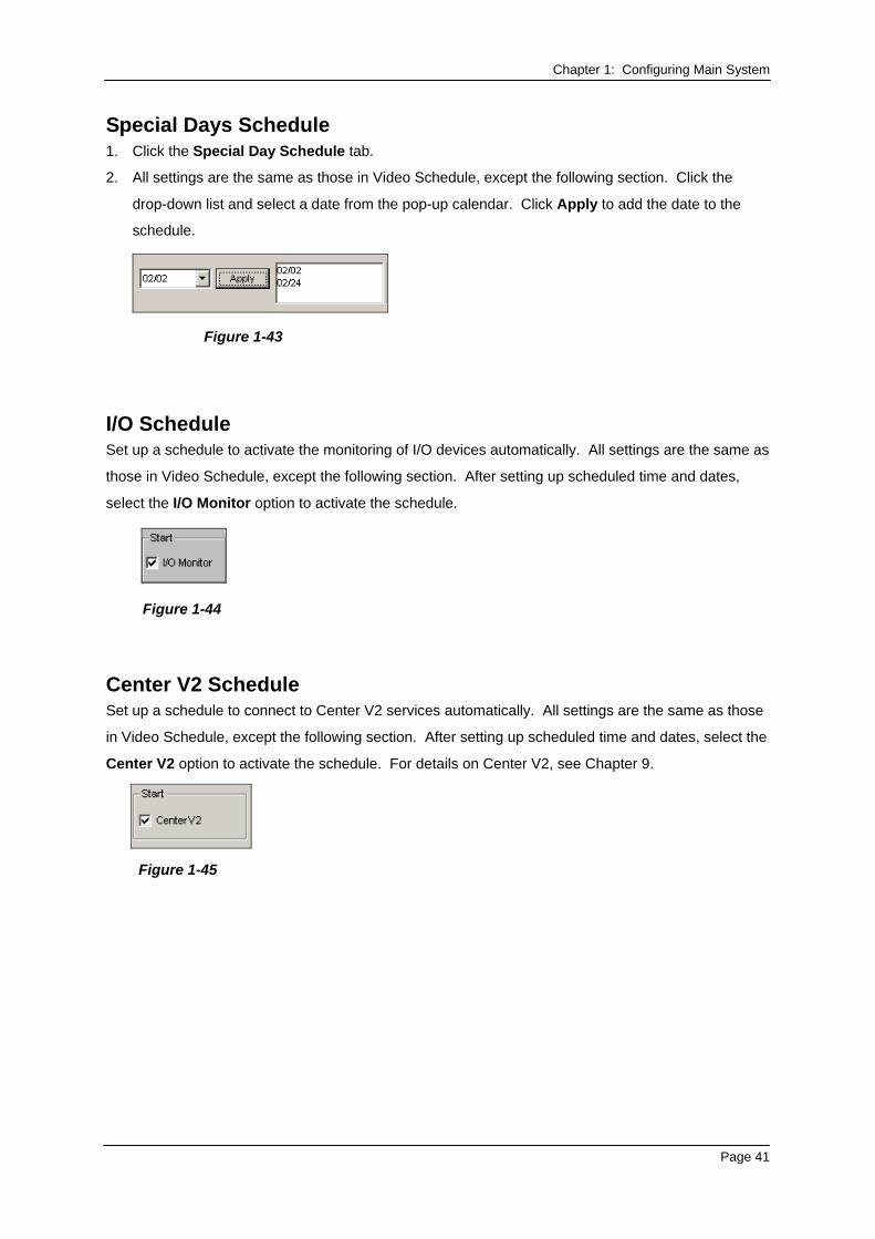
Chapter 1: Configuring Main System Special Days Schedule 1. Click the Special Day Schedule tab.
2. All settings are the same as those in Video Schedule, except the following section. Click the
drop-down list and select a date from the pop-up calendar. Click Apply to add the date to the
schedule.
Figure 1-43
I/O Schedule Set up a schedule to activate the monitoring of I/O devices automatically. All settings are the same as
those in Video Schedule, except the following section. After setting up scheduled time and dates,
select the I/O Monitor option to activate the schedule.
Figure 1-44
Center V2 Schedule Set up a schedule to connect to Center V2 services automatically. All settings are the same as those
in Video Schedule, except the following section. After setting up scheduled time and dates, select the
Center V2 option to activate the schedule. For details on Center V2, see Chapter 9.
Figure 1-45
Page 41
Chapter 1: Configuring Main System
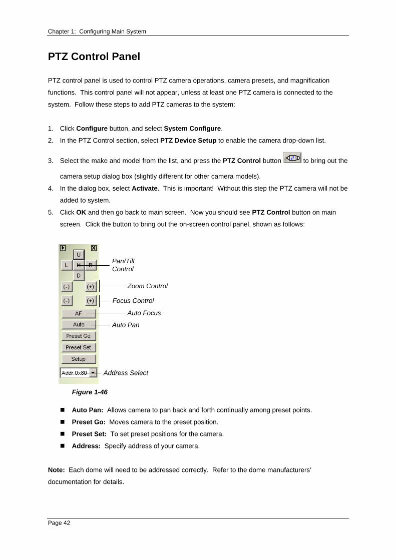
PTZ Control Panel
PTZ control panel is used to control PTZ camera operations, camera presets, and magnification
functions. This control panel will not appear, unless at least one PTZ camera is connected to the
system. Follow these steps to add PTZ cameras to the system:
1. Click Configure button, and select System Configure.
2. In the PTZ Control section, select PTZ Device Setup to enable the camera drop-down list.
3. Select the make and model from the list, and press the PTZ Control button to bring out the
camera setup dialog box (slightly different for other camera models).
4. In the dialog box, select Activate. This is important! Without this step the PTZ camera will not be
added to system.
5. Click OK and then go back to main screen. Now you should see PTZ Control button on main
screen. Click the button to bring out the on-screen control panel, shown as follows:
Pan/TiltControl
Zoom Control
Focus Control
Auto Focus
Auto Pan
Address Select
Figure 1-46
Auto Pan: Allows camera to pan back and forth continually among preset points.
Preset Go: Moves camera to the preset position.
Preset Set: To set preset positions for the camera.
Address: Specify address of your camera.
Note: Each dome will need to be addressed correctly. Refer to the dome manufacturers’
documentation for details.
Page 42
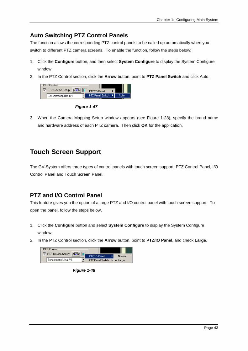
Chapter 1: Configuring Main System Auto Switching PTZ Control Panels The function allows the corresponding PTZ control panels to be called up automatically when you
switch to different PTZ camera screens. To enable the function, follow the steps below: 1. Click the Configure button, and then select System Configure to display the System Configure
window.
2. In the PTZ Control section, click the Arrow button, point to PTZ Panel Switch and click Auto.
Figure 1-47
3. When the Camera Mapping Setup window appears (see Figure 1-28), specify the brand name
and hardware address of each PTZ camera. Then click OK for the application.
Touch Screen Support
The GV-System offers three types of control panels with touch screen support: PTZ Control Panel, I/O
Control Panel and Touch Screen Panel.
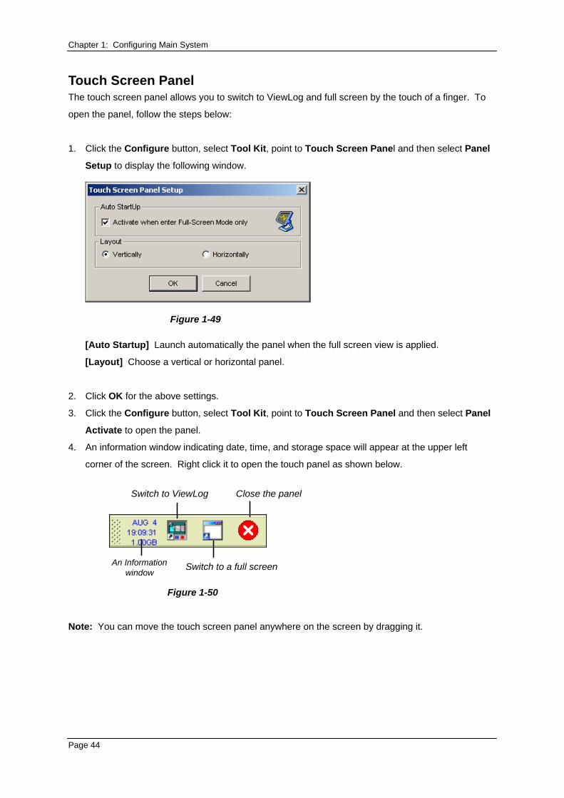
PTZ and I/O Control Panel This feature gives you the option of a large PTZ and I/O control panel with touch screen support. To
open the panel, follow the steps below.
1. Click the Configure button and select System Configure to display the System Configure
window.
2. In the PTZ Control section, click the Arrow button, point to PTZ/IO Panel, and check Large.
Figure 1-48
Page 43
Chapter 1: Configuring Main System Touch Screen Panel The touch screen panel allows you to switch to ViewLog and full screen by the touch of a finger. To
open the panel, follow the steps below:
1. Click the Configure button, select Tool Kit, point to Touch Screen Panel and then select Panel
Setup to display the following window.
Figure 1-49
[Auto Startup] Launch automatically the panel when the full screen view is applied.
[Layout] Choose a vertical or horizontal panel.
2. Click OK for the above settings.
3. Click the Configure button, select Tool Kit, point to Touch Screen Panel and then select Panel
Activate to open the panel.
4. An information window indicating date, time, and storage space will appear at the upper left
corner of the screen. Right click it to open the touch panel as shown below.
An Informationwindow
Switch to ViewLog
Switch to a full screen
Close the panel
Figure 1-50
Note: You can move the touch screen panel anywhere on the screen by dragging it.
Page 44
Chapter 1: Configuring Main System
Retrieving Images Using Object Index
The feature allows you to view the very first frame of a continuous movement in a video stream. With
Live Object Index, you may view the most recent 50 frames captured. With Object Index Search, you
may easily locate a desired event and instantly play it back by double-clicking on the image frame.
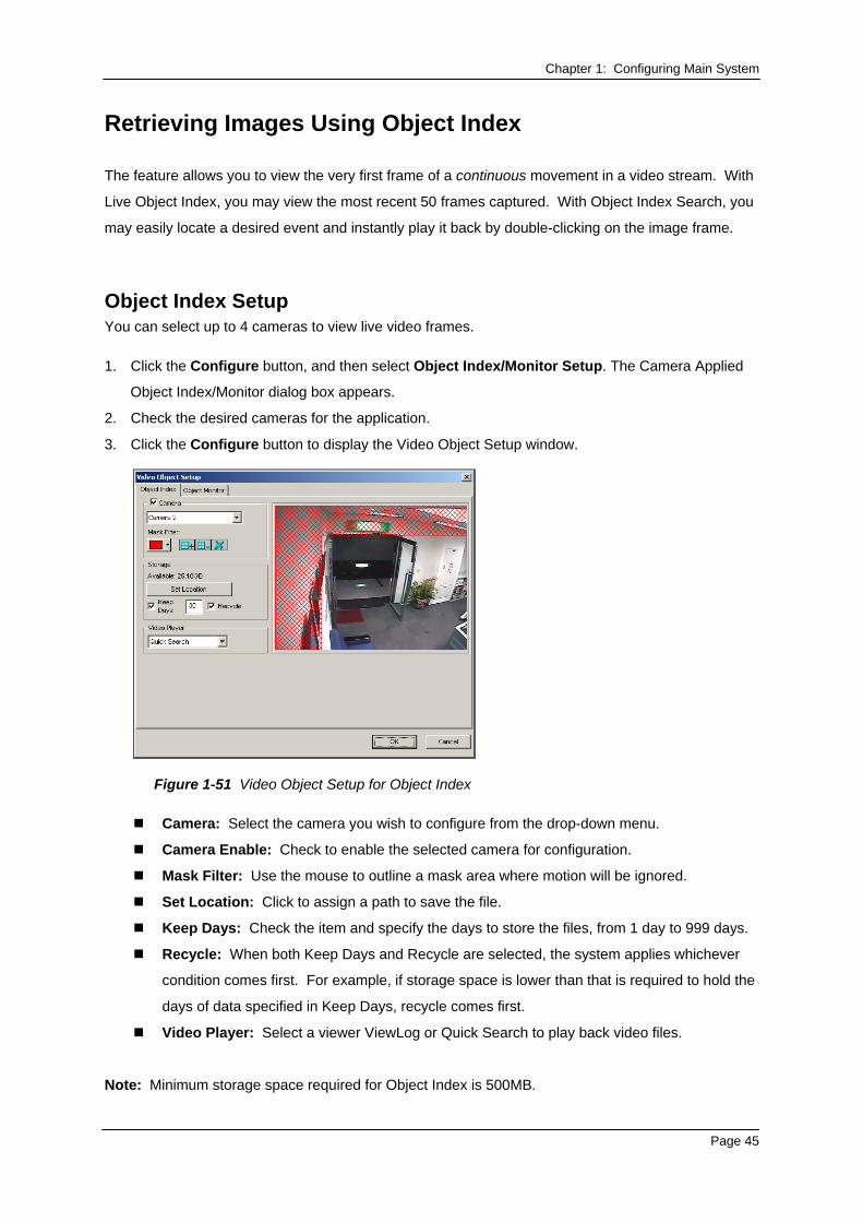
Object Index Setup You can select up to 4 cameras to view live video frames. 1. Click the Configure button, and then select Object Index/Monitor Setup. The Camera Applied
Object Index/Monitor dialog box appears.
2. Check the desired cameras for the application.
3. Click the Configure button to display the Video Object Setup window.
Figure 1-51 Video Object Setup for Object Index
Camera: Select the camera you wish to configure from the drop-down menu.
Camera Enable: Check to enable the selected camera for configuration.
Mask Filter: Use the mouse to outline a mask area where motion will be ignored.
Set Location: Click to assign a path to save the file.
Keep Days: Check the item and specify the days to store the files, from 1 day to 999 days.
Recycle: When both Keep Days and Recycle are selected, the system applies whichever
condition comes first. For example, if storage space is lower than that is required to hold the
days of data specified in Keep Days, recycle comes first.
Video Player: Select a viewer ViewLog or Quick Search to play back video files.
Note: Minimum storage space required for Object Index is 500MB.
Page 45
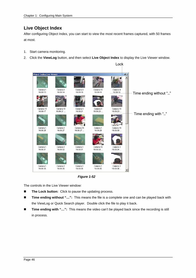
Chapter 1: Configuring Main System Live Object Index After configuring Object Index, you can start to view the most recent frames captured, with 50 frames
at most.
1. Start camera monitoring.
2. Click the ViewLog button, and then select Live Object Index to display the Live Viewer window.
Lock
Time ending without “…”
Time ending with “…”
Figure 1-52
The controls in the Live Viewer window:
The Lock button: Click to pause the updating process.
Time ending without “…”: This means the file is a complete one and can be played back with
the ViewLog or Quick Search player. Double click the file to play it back.
Time ending with “…”: This means the video can’t be played back since the recording is still
in process.
Page 46
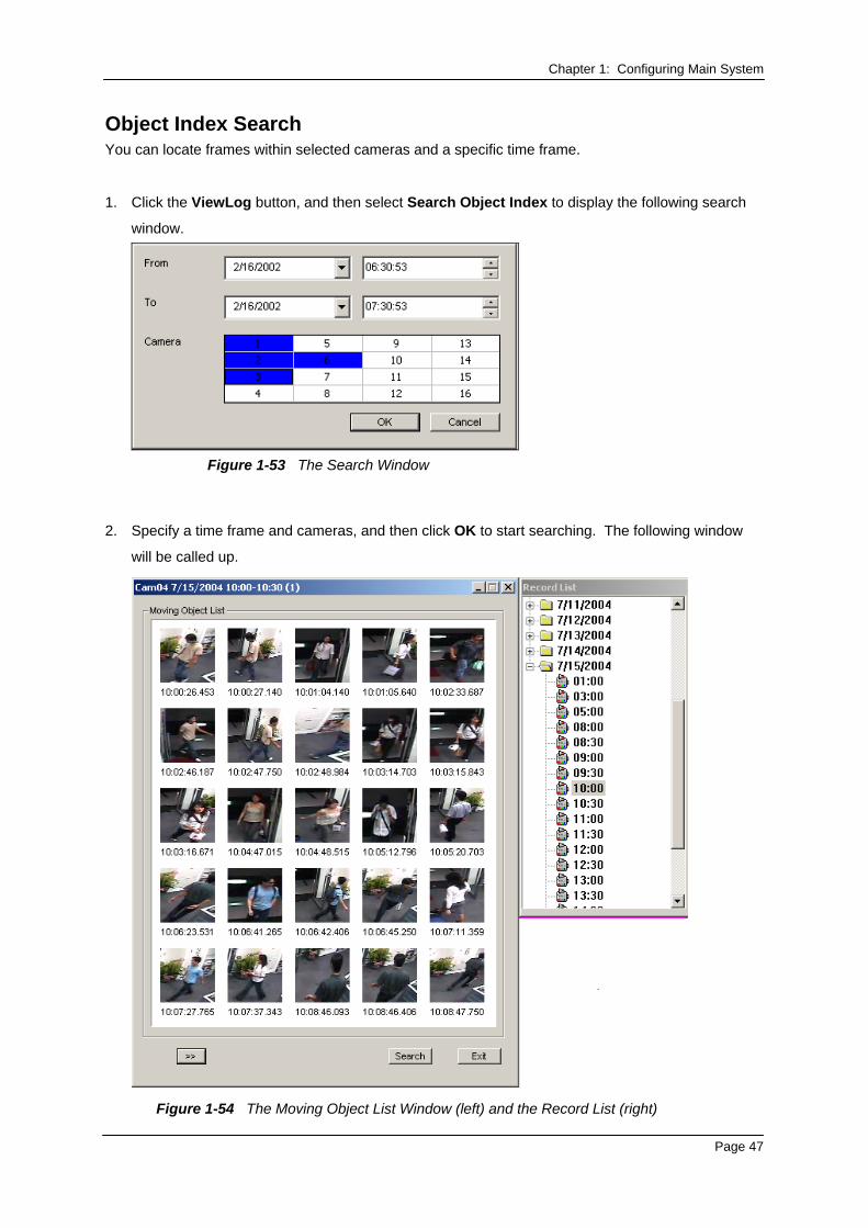
Chapter 1: Configuring Main System Object Index Search You can locate frames within selected cameras and a specific time frame.
1. Click the ViewLog button, and then select Search Object Index to display the following search
window.
Figure 1-53 The Search Window
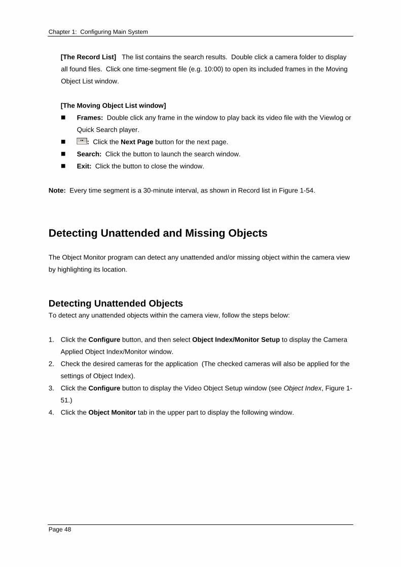
2. Specify a time frame and cameras, and then click OK to start searching. The following window
will be called up.
Figure 1-54 The Moving Object List Window (left) and the Record List (right)
Page 47
Chapter 1: Configuring Main System
[The Record List] The list contains the search results. Double click a camera folder to display
all found files. Click one time-segment file (e.g. 10:00) to open its included frames in the Moving
Object List window.
[The Moving Object List window]
Frames: Double click any frame in the window to play back its video file with the Viewlog or
Quick Search player.
: Click the Next Page button for the next page.
Search: Click the button to launch the search window.
Exit: Click the button to close the window.
Note: Every time segment is a 30-minute interval, as shown in Record list in Figure 1-54.
Detecting Unattended and Missing Objects
The Object Monitor program can detect any unattended and/or missing object within the camera view
by highlighting its location.
Detecting Unattended Objects To detect any unattended objects within the camera view, follow the steps below:
1. Click the Configure button, and then select Object Index/Monitor Setup to display the Camera
Applied Object Index/Monitor window.
2. Check the desired cameras for the application (The checked cameras will also be applied for the
settings of Object Index).
3. Click the Configure button to display the Video Object Setup window (see Object Index, Figure 1-
51.)
4. Click the Object Monitor tab in the upper part to display the following window.
Page 48
Chapter 1: Configuring Main System
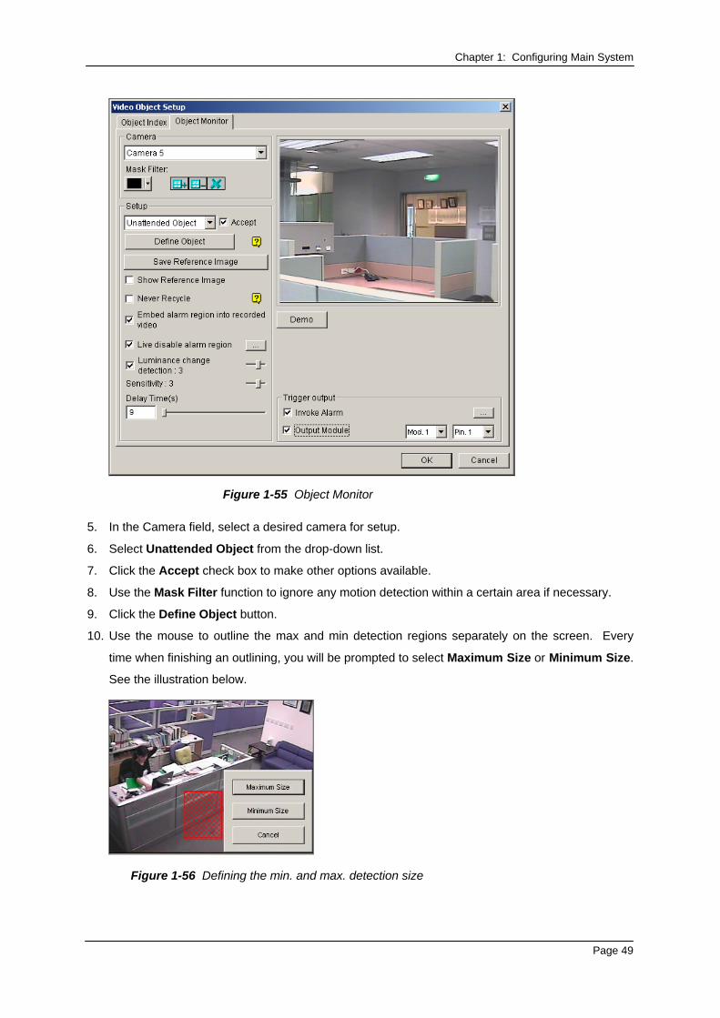
Figure 1-55 Object Monitor
5. In the Camera field, select a desired camera for setup.
6. Select Unattended Object from the drop-down list.
7. Click the Accept check box to make other options available.
8. Use the Mask Filter function to ignore any motion detection within a certain area if necessary.
9. Click the Define Object button.
10. Use the mouse to outline the max and min detection regions separately on the screen. Every
time when finishing an outlining, you will be prompted to select Maximum Size or Minimum Size.
See the illustration below.
Figure 1-56 Defining the min. and max. detection size
Page 49
Chapter 1: Configuring Main System 11. Click the items of Show Max and Show Min in the lower of the window one by one to check your
defined sizes.
12. Click the Done button to finish the defining.
13. Click the Save Reference Image button to save the image as a reference view.
14. To set up other options, see Other controls in the Video Object Setup window on page 67.
15. Click the OK button to apply the settings and close the window.
16. Start camera monitoring for the application.
When an unattended object appears and remains stationary for 9 seconds, its location will be
highlighted, the selected alarm and output will be activated, and the event will be recorded in System
Log for later retrieval.
Detecting Missing Objects To detect any object missing from the camera view, follow the steps below:
1. Follow the step 1 to 4 in the above Detecting Unattended Objects section to display the Video
Object Setup window. Refer to Figure 2-9.
2. In the Camera field, select a desired camera for configuration.
3. Select Missing Object from the drop-down list.
4. Click the Accept check box to make other options available.
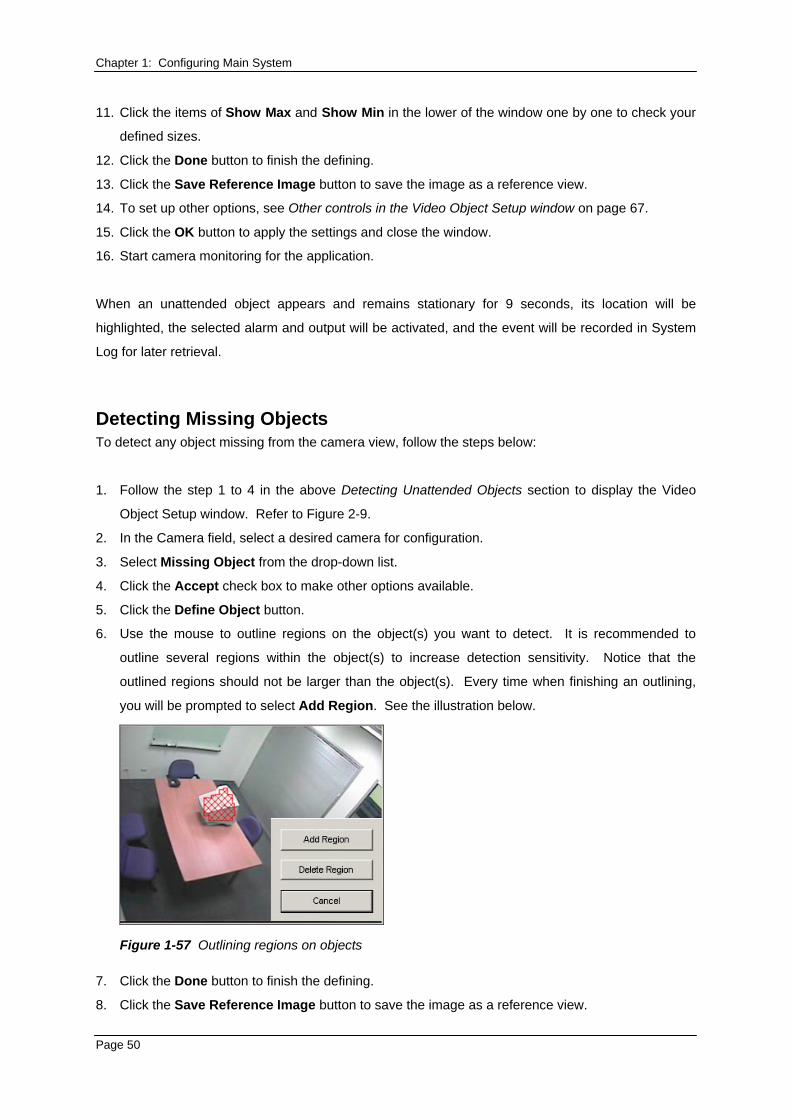
5. Click the Define Object button.
6. Use the mouse to outline regions on the object(s) you want to detect. It is recommended to
outline several regions within the object(s) to increase detection sensitivity. Notice that the
outlined regions should not be larger than the object(s). Every time when finishing an outlining,
you will be prompted to select Add Region. See the illustration below.
Figure 1-57 Outlining regions on objects
7. Click the Done button to finish the defining.
8. Click the Save Reference Image button to save the image as a reference view.
Page 50
Chapter 1: Configuring Main System 9. To set up other options, see Other controls in the Video Object Setup window below.
10. Click the OK button to apply the settings and close the window.
11. Start camera monitoring for the application.
When any object, which you have outlined the regions for, disappears from the camera view for 3
seconds, its location will be highlighted, the selected alarm and output will be activated, and the event
will be recorded in System Log for later retrieval.
Other controls in the Video Object Setup window:
Show Reference Image: Click to view the saved reference image.
Never Recycle: When the item is checked, the events of unattended and missing objects won’t
be recycled by the system.
Embed Alarm Region into Recorded Video: This option will contain the flashing alert boxes in
the recorded files so you can easily find out suspicious events during playback. Note that if you
are used to searching suspicious events with Object Search, do not enable this option. These
flashing boxes can cause false alarms.
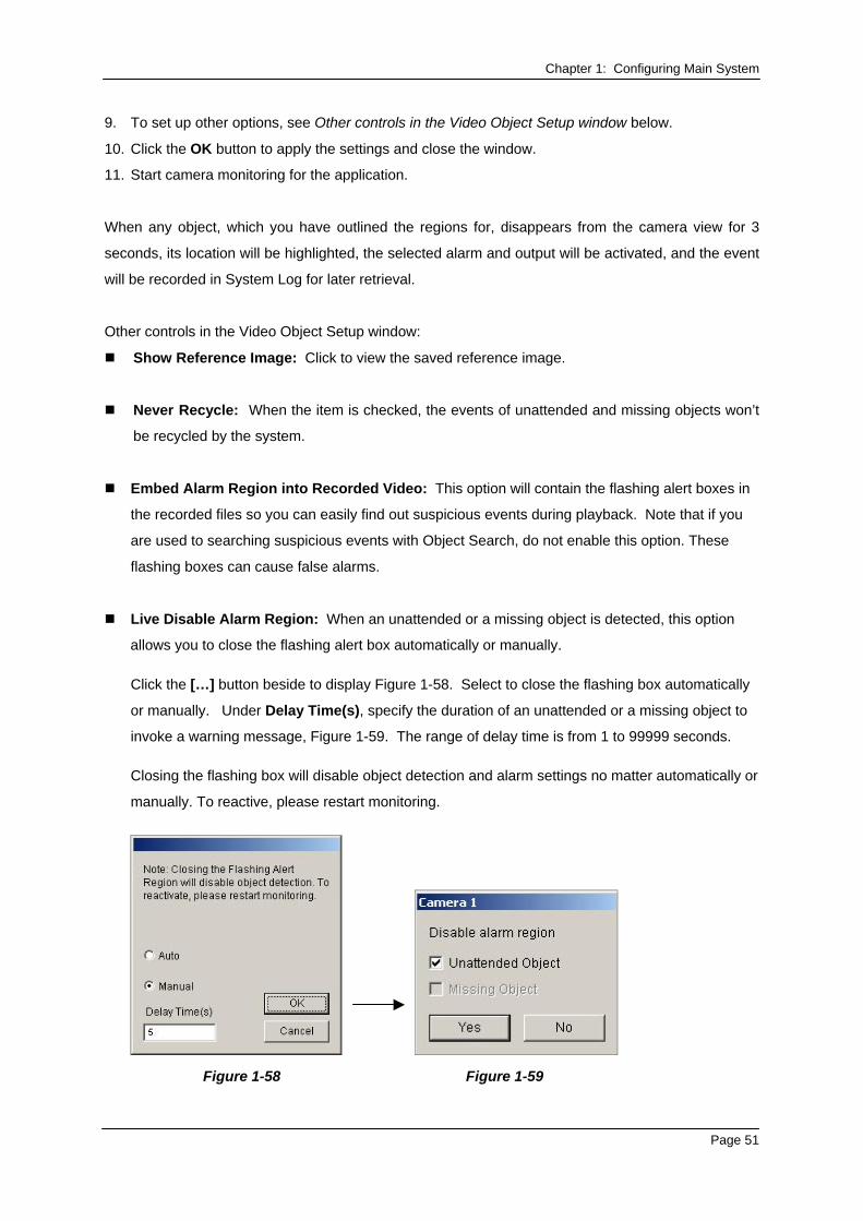
Live Disable Alarm Region: When an unattended or a missing object is detected, this option
allows you to close the flashing alert box automatically or manually.
Click the […] button beside to display Figure 1-58. Select to close the flashing box automatically
or manually. Under Delay Time(s), specify the duration of an unattended or a missing object to
invoke a warning message, Figure 1-59. The range of delay time is from 1 to 99999 seconds. Closing the flashing box will disable object detection and alarm settings no matter automatically or
manually. To reactive, please restart monitoring.
Figure 1-58 Figure 1-59
Page 51

Chapter 1: Configuring Main System Luminance Change Detection: This option may suspend object detection when the lighting
condition is poor so as to avoid false detection. Use the slide bar to adjust the level of detection
from 1 to 5. The higher the level is, the more sensitive the system is to luminance change. When
luminance change reaches the level you set, the system will stop object detection.
Sensitivity: Use the slide bar to increase or decrease detection sensitivity if necessary.
Delay Time: This option allows you to specify the duration of an object missing or unattended to
invoke the detection.
Unattended Object: The duration is from 3 to 1800 seconds, with 3 seconds as default.
For example, suppose you choose 12 seconds. When an unattended object appears in the
camera view for 12 seconds, its location will be highlighted.
Missing Object: The duration is from 3 to 1800 seconds, with 3 seconds as default. For
example, suppose you choose 9 seconds. When a defined object disappears from the camera
view for 9 seconds, its location will be highlighted.
Invoke Alarm: Enables the computer alarm when any unattended and/or missing objects are
detected. Click the […] button next to the item to assign a .wav sound file.
Output Module: Activates the output device when any unattended and/or missing object is
detected. Click the […] button next to the item to assign an installed output module and a pin
number.
Demo: Click to see the demonstration from actual DVR applications.
Page 52
Chapter 1: Configuring Main System
Object Tracking and Zooming
Object Tracking provides you the real-time tracking and automatic magnification of a single moving
object by the combination of one PTZ camera and one stationary camera. If only one PTZ camera is
available, it can be applied for Object Zooming, letting you configure four critical views for real-time
zooming. The Object Tracking and Object Zooming functions can be combined together by
completing both settings.
Object Tracking For the tracking function, you need one PTZ camera applied for tracking and one stationary camera
set for a fixed view. Currently, GV- System only supports Sensormatic, PelcoSpetra and Messoa PTZ.
Install the PTZ camera and the stationary camera in the best possible closing position, so the focus of
both could be similar.
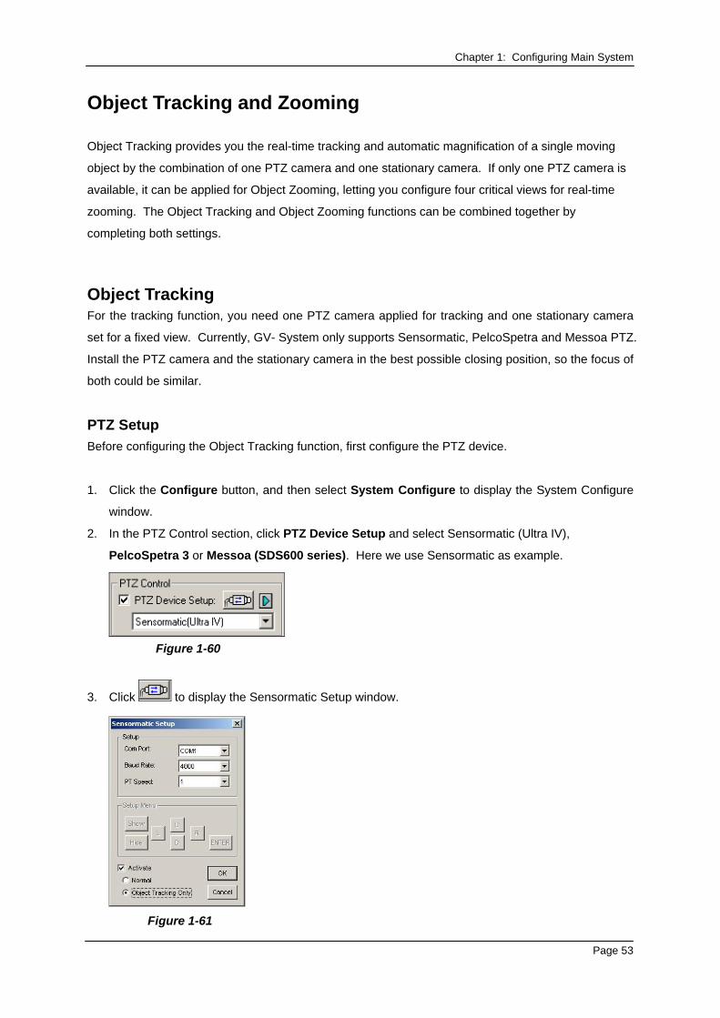
PTZ Setup Before configuring the Object Tracking function, first configure the PTZ device.
1. Click the Configure button, and then select System Configure to display the System Configure
window.
2. In the PTZ Control section, click PTZ Device Setup and select Sensormatic (Ultra IV),
PelcoSpetra 3 or Messoa (SDS600 series). Here we use Sensormatic as example.
Figure 1-60
3. Click to display the Sensormatic Setup window.
Figure 1-61
Page 53
Chapter 1: Configuring Main System 4. Enter Com Port, Baud Rate and PT Speed of the PTZ camera.
5. Check the Activate item and select Object Tracking Only.
6. Click OK to apply the settings.
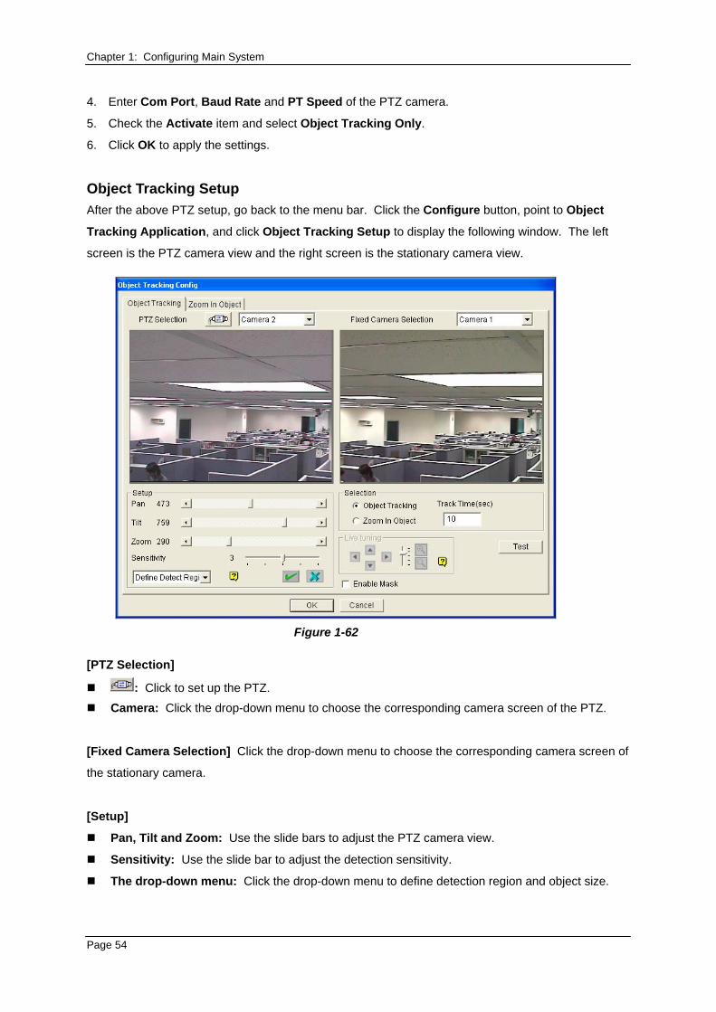
Object Tracking Setup After the above PTZ setup, go back to the menu bar. Click the Configure button, point to Object
Tracking Application, and click Object Tracking Setup to display the following window. The left
screen is the PTZ camera view and the right screen is the stationary camera view.
Figure 1-62
[PTZ Selection]
: Click to set up the PTZ.
Camera: Click the drop-down menu to choose the corresponding camera screen of the PTZ.
[Fixed Camera Selection] Click the drop-down menu to choose the corresponding camera screen of
the stationary camera.
[Setup]
Pan, Tilt and Zoom: Use the slide bars to adjust the PTZ camera view.
Sensitivity: Use the slide bar to adjust the detection sensitivity.
The drop-down menu: Click the drop-down menu to define detection region and object size.
Page 54
Chapter 1: Configuring Main System [Selection]
Object Tracking: Click to specify the tracking time.
Zoom in Object: Click to specify the idle time.
[Live Tuning] Adjust directions and the desired level of zooming.
[Enable Mask] Click to display the mask on the defined detection region.
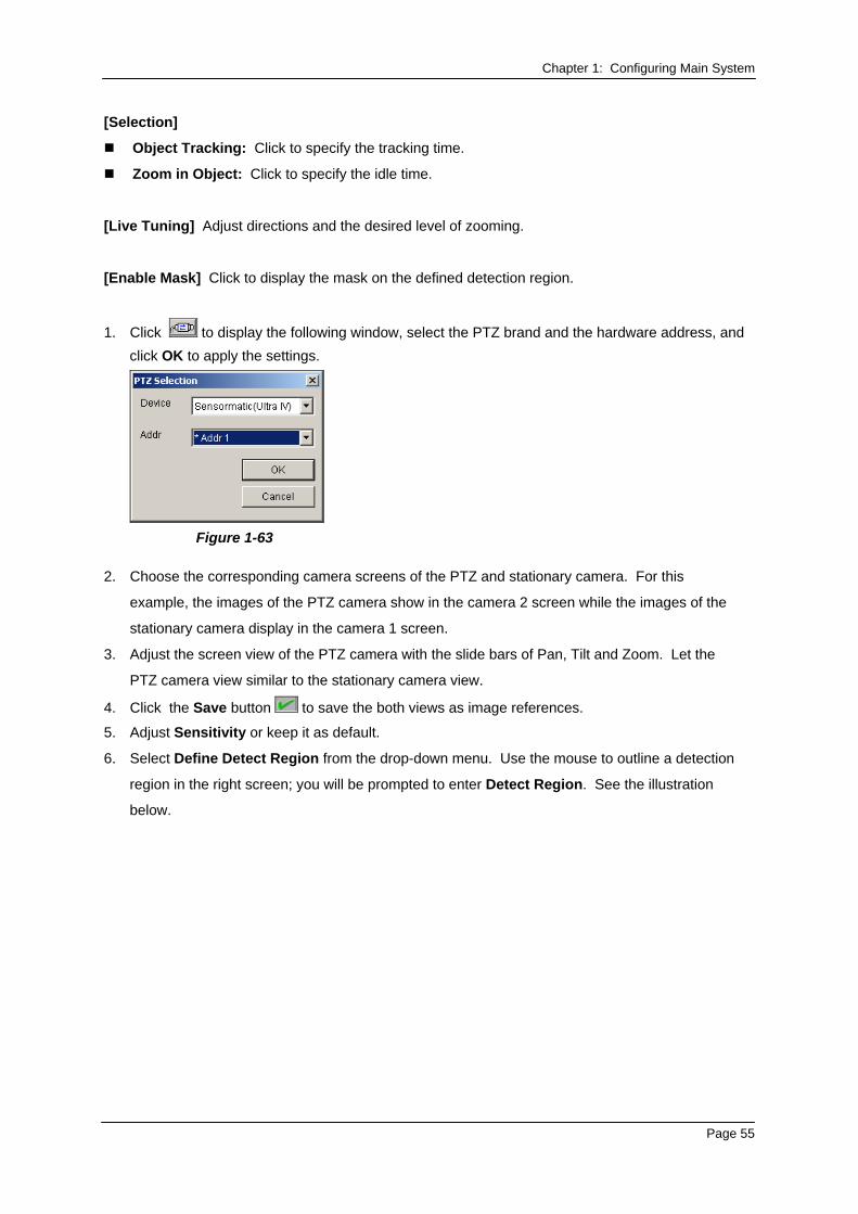
1. Click to display the following window, select the PTZ brand and the hardware address, and click OK to apply the settings.
Figure 1-63
2. Choose the corresponding camera screens of the PTZ and stationary camera. For this
example, the images of the PTZ camera show in the camera 2 screen while the images of the
stationary camera display in the camera 1 screen.
3. Adjust the screen view of the PTZ camera with the slide bars of Pan, Tilt and Zoom. Let the
PTZ camera view similar to the stationary camera view.
4. Click the Save button to save the both views as image references.
5. Adjust Sensitivity or keep it as default.
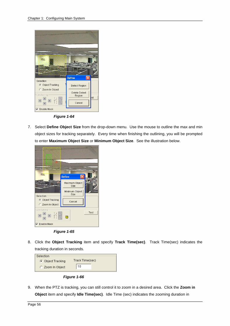
6. Select Define Detect Region from the drop-down menu. Use the mouse to outline a detection
region in the right screen; you will be prompted to enter Detect Region. See the illustration
below.
Page 55
Chapter 1: Configuring Main System
Figure 1-64
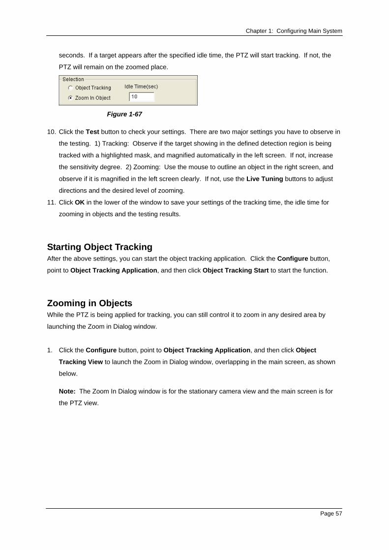
7. Select Define Object Size from the drop-down menu. Use the mouse to outline the max and min
object sizes for tracking separately. Every time when finishing the outlining, you will be prompted
to enter Maximum Object Size or Minimum Object Size. See the illustration below.
Figure 1-65
8. Click the Object Tracking item and specify Track Time(sec). Track Time(sec) indicates the
tracking duration in seconds.
Figure 1-66
9. When the PTZ is tracking, you can still control it to zoom in a desired area. Click the Zoom in
Object item and specify Idle Time(sec). Idle Time (sec) indicates the zooming duration in
Page 56
Chapter 1: Configuring Main System
seconds. If a target appears after the specified idle time, the PTZ will start tracking. If not, the
PTZ will remain on the zoomed place.
Figure 1-67
10. Click the Test button to check your settings. There are two major settings you have to observe in
the testing. 1) Tracking: Observe if the target showing in the defined detection region is being
tracked with a highlighted mask, and magnified automatically in the left screen. If not, increase
the sensitivity degree. 2) Zooming: Use the mouse to outline an object in the right screen, and
observe if it is magnified in the left screen clearly. If not, use the Live Tuning buttons to adjust
directions and the desired level of zooming.
11. Click OK in the lower of the window to save your settings of the tracking time, the idle time for
zooming in objects and the testing results.
Starting Object Tracking After the above settings, you can start the object tracking application. Click the Configure button,
point to Object Tracking Application, and then click Object Tracking Start to start the function.
Zooming in Objects While the PTZ is being applied for tracking, you can still control it to zoom in any desired area by
launching the Zoom in Dialog window.
1. Click the Configure button, point to Object Tracking Application, and then click Object
Tracking View to launch the Zoom in Dialog window, overlapping in the main screen, as shown
below.
Note: The Zoom In Dialog window is for the stationary camera view and the main screen is for
the PTZ view.
Page 57
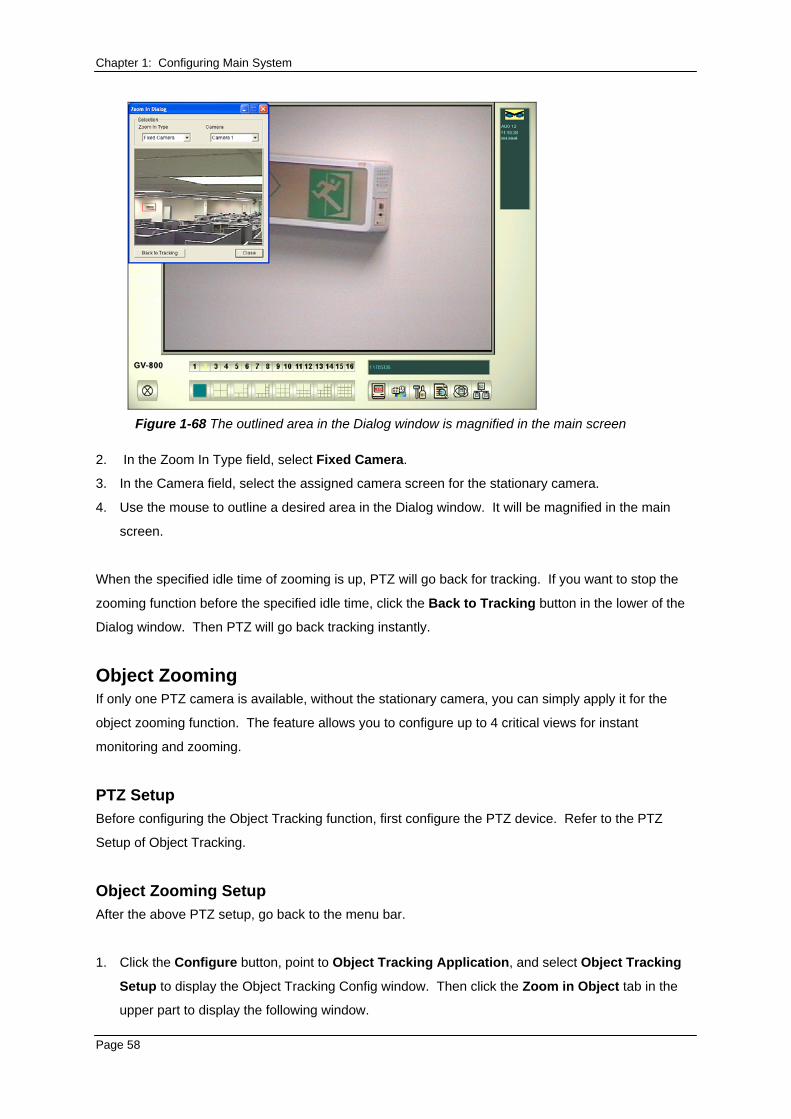
Chapter 1: Configuring Main System
Figure 1-68 The outlined area in the Dialog window is magnified in the main screen
2. In the Zoom In Type field, select Fixed Camera.
3. In the Camera field, select the assigned camera screen for the stationary camera.
4. Use the mouse to outline a desired area in the Dialog window. It will be magnified in the main
screen.
When the specified idle time of zooming is up, PTZ will go back for tracking. If you want to stop the
zooming function before the specified idle time, click the Back to Tracking button in the lower of the
Dialog window. Then PTZ will go back tracking instantly.
Object Zooming If only one PTZ camera is available, without the stationary camera, you can simply apply it for the
object zooming function. The feature allows you to configure up to 4 critical views for instant
monitoring and zooming.
PTZ Setup Before configuring the Object Tracking function, first configure the PTZ device. Refer to the PTZ
Setup of Object Tracking.
Object Zooming Setup After the above PTZ setup, go back to the menu bar.
1. Click the Configure button, point to Object Tracking Application, and select Object Tracking
Setup to display the Object Tracking Config window. Then click the Zoom in Object tab in the
upper part to display the following window.
Page 58
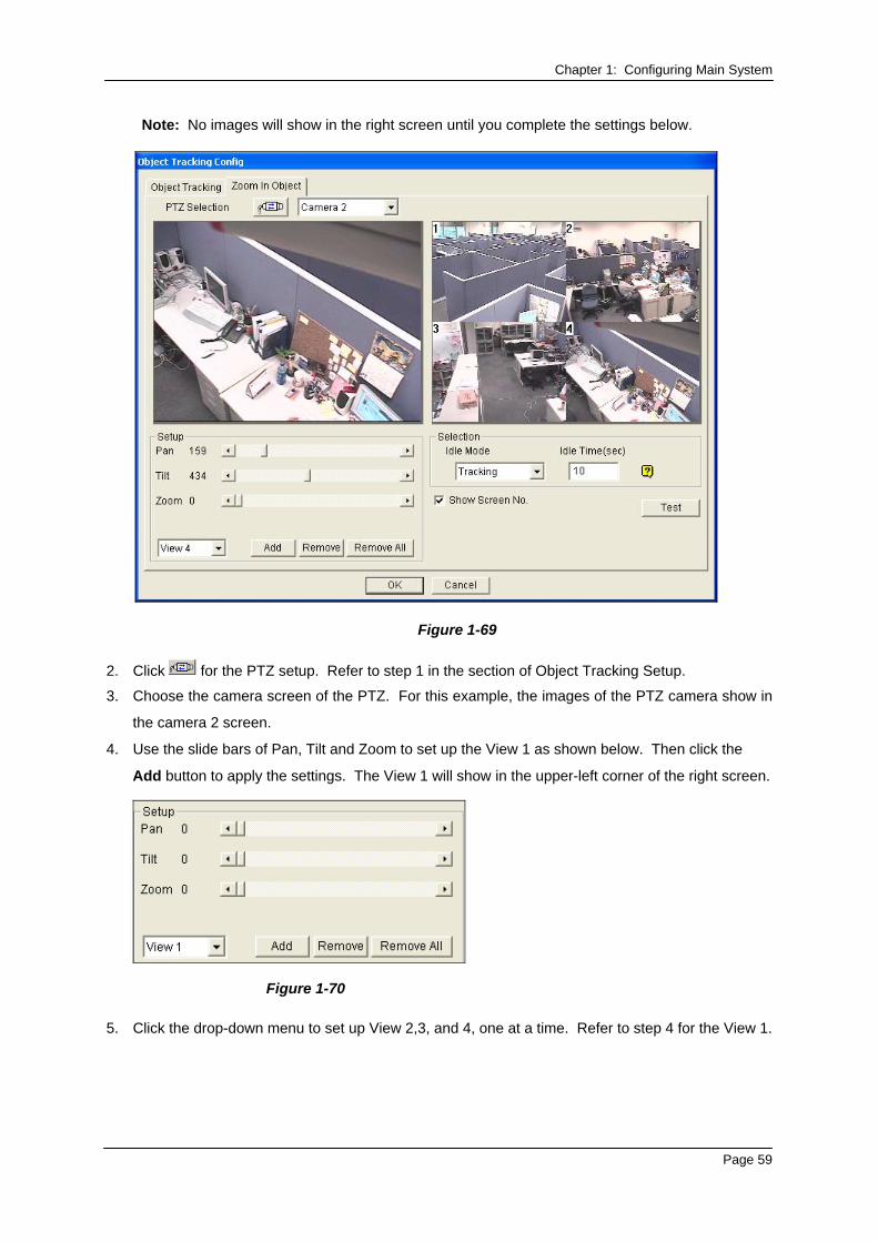
Chapter 1: Configuring Main System
Note: No images will show in the right screen until you complete the settings below.
Figure 1-69
2. Click for the PTZ setup. Refer to step 1 in the section of Object Tracking Setup.
3. Choose the camera screen of the PTZ. For this example, the images of the PTZ camera show in
the camera 2 screen.
4. Use the slide bars of Pan, Tilt and Zoom to set up the View 1 as shown below. Then click the
Add button to apply the settings. The View 1 will show in the upper-left corner of the right screen.
Figure 1-70
5. Click the drop-down menu to set up View 2,3, and 4, one at a time. Refer to step 4 for the View 1.
Page 59
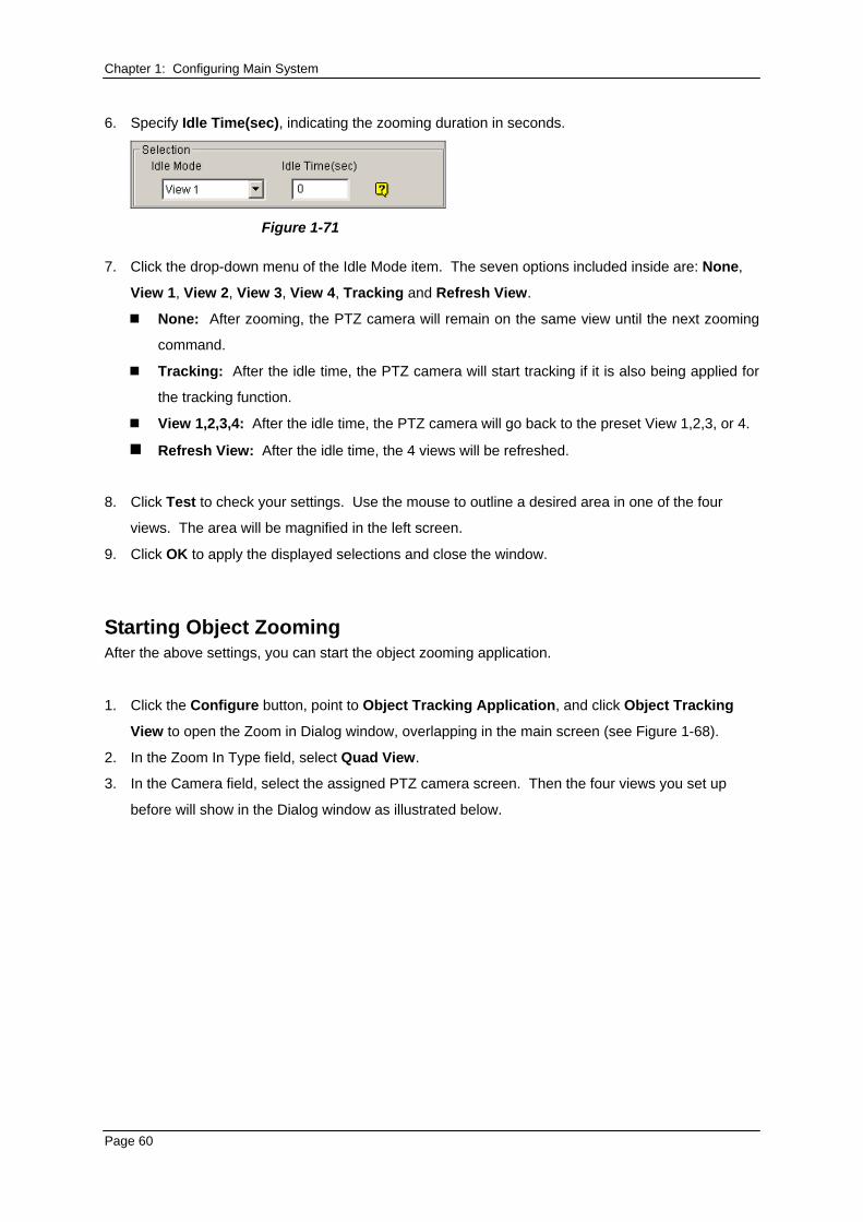
Chapter 1: Configuring Main System 6. Specify Idle Time(sec), indicating the zooming duration in seconds.
Figure 1-71
7. Click the drop-down menu of the Idle Mode item. The seven options included inside are: None,
View 1, View 2, View 3, View 4, Tracking and Refresh View. None: After zooming, the PTZ camera will remain on the same view until the next zooming
command.
Tracking: After the idle time, the PTZ camera will start tracking if it is also being applied for
the tracking function.
View 1,2,3,4: After the idle time, the PTZ camera will go back to the preset View 1,2,3, or 4.
Refresh View: After the idle time, the 4 views will be refreshed. 8. Click Test to check your settings. Use the mouse to outline a desired area in one of the four
views. The area will be magnified in the left screen.
9. Click OK to apply the displayed selections and close the window.
Starting Object Zooming After the above settings, you can start the object zooming application.
1. Click the Configure button, point to Object Tracking Application, and click Object Tracking
View to open the Zoom in Dialog window, overlapping in the main screen (see Figure 1-68).
2. In the Zoom In Type field, select Quad View.
3. In the Camera field, select the assigned PTZ camera screen. Then the four views you set up
before will show in the Dialog window as illustrated below.
Page 60
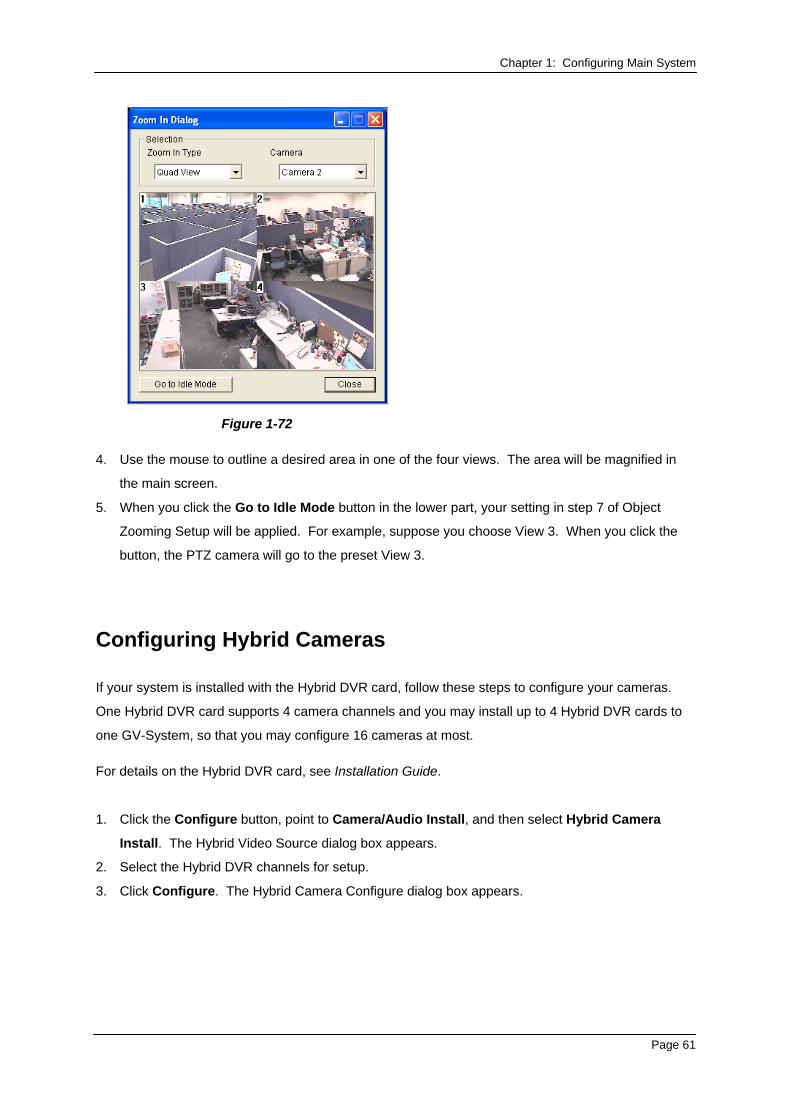
Chapter 1: Configuring Main System
Figure 1-72
4. Use the mouse to outline a desired area in one of the four views. The area will be magnified in
the main screen.
5. When you click the Go to Idle Mode button in the lower part, your setting in step 7 of Object
Zooming Setup will be applied. For example, suppose you choose View 3. When you click the
button, the PTZ camera will go to the preset View 3.
Configuring Hybrid Cameras
If your system is installed with the Hybrid DVR card, follow these steps to configure your cameras.
One Hybrid DVR card supports 4 camera channels and you may install up to 4 Hybrid DVR cards to
one GV-System, so that you may configure 16 cameras at most. For details on the Hybrid DVR card, see Installation Guide.
1. Click the Configure button, point to Camera/Audio Install, and then select Hybrid Camera
Install. The Hybrid Video Source dialog box appears.
2. Select the Hybrid DVR channels for setup.
3. Click Configure. The Hybrid Camera Configure dialog box appears.
Page 61
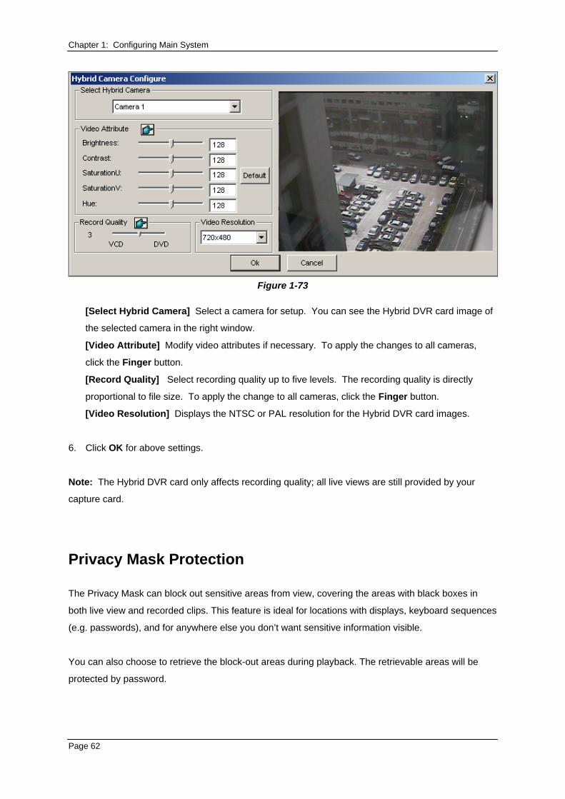
Chapter 1: Configuring Main System
Figure 1-73
[Select Hybrid Camera] Select a camera for setup. You can see the Hybrid DVR card image of
the selected camera in the right window.
[Video Attribute] Modify video attributes if necessary. To apply the changes to all cameras,
click the Finger button.
[Record Quality] Select recording quality up to five levels. The recording quality is directly
proportional to file size. To apply the change to all cameras, click the Finger button.
[Video Resolution] Displays the NTSC or PAL resolution for the Hybrid DVR card images.
6. Click OK for above settings.
Note: The Hybrid DVR card only affects recording quality; all live views are still provided by your
capture card.
Privacy Mask Protection
The Privacy Mask can block out sensitive areas from view, covering the areas with black boxes in
both live view and recorded clips. This feature is ideal for locations with displays, keyboard sequences
(e.g. passwords), and for anywhere else you don’t want sensitive information visible.
You can also choose to retrieve the block-out areas during playback. The retrievable areas will be
protected by password.
Page 62
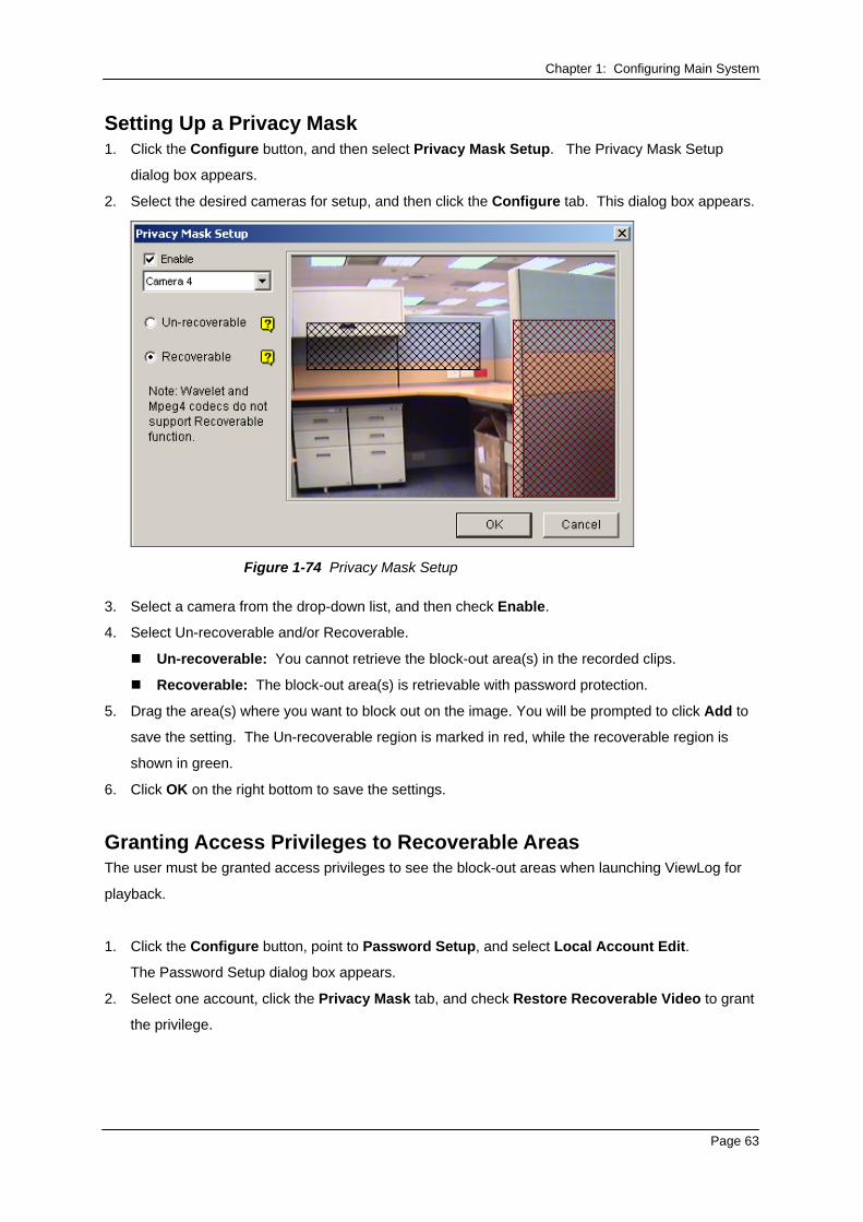
Chapter 1: Configuring Main System Setting Up a Privacy Mask 1. Click the Configure button, and then select Privacy Mask Setup. The Privacy Mask Setup
dialog box appears.
2. Select the desired cameras for setup, and then click the Configure tab. This dialog box appears.
Figure 1-74 Privacy Mask Setup
3. Select a camera from the drop-down list, and then check Enable.
4. Select Un-recoverable and/or Recoverable.
Un-recoverable: You cannot retrieve the block-out area(s) in the recorded clips.
Recoverable: The block-out area(s) is retrievable with password protection.
5. Drag the area(s) where you want to block out on the image. You will be prompted to click Add to
save the setting. The Un-recoverable region is marked in red, while the recoverable region is
shown in green.
6. Click OK on the right bottom to save the settings.
Granting Access Privileges to Recoverable Areas The user must be granted access privileges to see the block-out areas when launching ViewLog for
playback.
1. Click the Configure button, point to Password Setup, and select Local Account Edit.
The Password Setup dialog box appears.
2. Select one account, click the Privacy Mask tab, and check Restore Recoverable Video to grant
the privilege.
Page 63
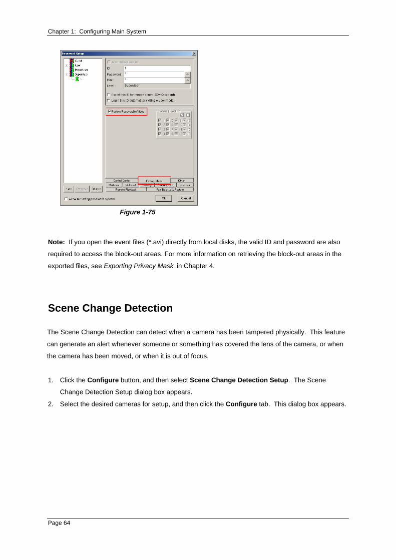
Chapter 1: Configuring Main System
Figure 1-75
Note: If you open the event files (*.avi) directly from local disks, the valid ID and password are also
required to access the block-out areas. For more information on retrieving the block-out areas in the
exported files, see Exporting Privacy Mask in Chapter 4.
Scene Change Detection
The Scene Change Detection can detect when a camera has been tampered physically. This feature
can generate an alert whenever someone or something has covered the lens of the camera, or when
the camera has been moved, or when it is out of focus.
1. Click the Configure button, and then select Scene Change Detection Setup. The Scene
Change Detection Setup dialog box appears.
2. Select the desired cameras for setup, and then click the Configure tab. This dialog box appears.
Page 64
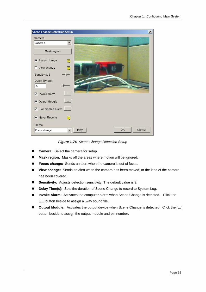
Chapter 1: Configuring Main System
Figure 1-76 Scene Change Detection Setup
Camera: Select the camera for setup.
Mask region: Masks off the areas where motion will be ignored.
Focus change: Sends an alert when the camera is out of focus.
View change: Sends an alert when the camera has been moved, or the lens of the camera
has been covered.
Sensitivity: Adjusts detection sensitivity. The default value is 3.
Delay Time(s): Sets the duration of Scene Change to record to System Log.
Invoke Alarm: Activates the computer alarm when Scene Change is detected. Click the
[…] button beside to assign a .wav sound file.
Output Module: Activates the output device when Scene Change is detected. Click the […]
button beside to assign the output module and pin number.
Page 65
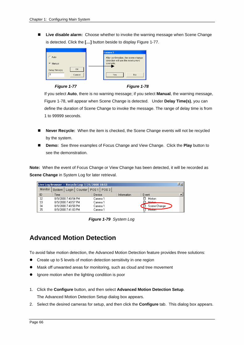
Chapter 1: Configuring Main System
Live disable alarm: Choose whether to invoke the warning message when Scene Change
is detected. Click the […] button beside to display Figure 1-77.
Figure 1-77 Figure 1-78
If you select Auto, there is no warning message; if you select Manual, the warning message,
Figure 1-78, will appear when Scene Change is detected. Under Delay Time(s), you can
define the duration of Scene Change to invoke the message. The range of delay time is from
1 to 99999 seconds.
Never Recycle: When the item is checked, the Scene Change events will not be recycled
by the system.
Demo: See three examples of Focus Change and View Change. Click the Play button to
see the demonstration.
Note: When the event of Focus Change or View Change has been detected, it will be recorded as
Scene Change in System Log for later retrieval.
Figure 1-79 System Log
Advanced Motion Detection
To avoid false motion detection, the Advanced Motion Detection feature provides three solutions:
Create up to 5 levels of motion detection sensitivity in one region
Mask off unwanted areas for monitoring, such as cloud and tree movement
Ignore motion when the lighting condition is poor
1. Click the Configure button, and then select Advanced Motion Detection Setup.
The Advanced Motion Detection Setup dialog box appears.
2. Select the desired cameras for setup, and then click the Configure tab. This dialog box appears.
Page 66
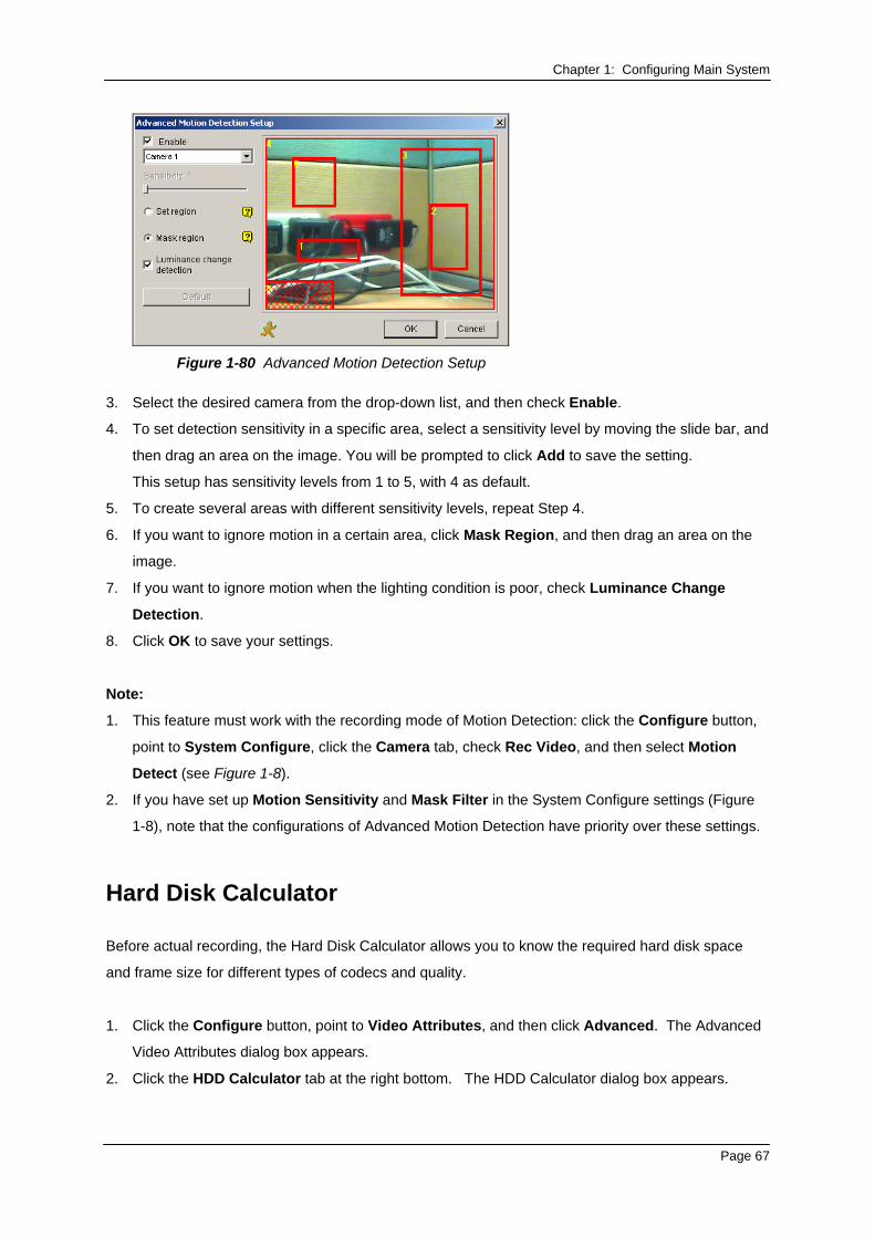
Chapter 1: Configuring Main System
Figure 1-80 Advanced Motion Detection Setup
3. Select the desired camera from the drop-down list, and then check Enable.
4. To set detection sensitivity in a specific area, select a sensitivity level by moving the slide bar, and
then drag an area on the image. You will be prompted to click Add to save the setting.
This setup has sensitivity levels from 1 to 5, with 4 as default.
5. To create several areas with different sensitivity levels, repeat Step 4.
6. If you want to ignore motion in a certain area, click Mask Region, and then drag an area on the
image.
7. If you want to ignore motion when the lighting condition is poor, check Luminance Change
Detection.
8. Click OK to save your settings.
Note:
1. This feature must work with the recording mode of Motion Detection: click the Configure button,
point to System Configure, click the Camera tab, check Rec Video, and then select Motion
Detect (see Figure 1-8).
2. If you have set up Motion Sensitivity and Mask Filter in the System Configure settings (Figure
1-8), note that the configurations of Advanced Motion Detection have priority over these settings.
Hard Disk Calculator
Before actual recording, the Hard Disk Calculator allows you to know the required hard disk space
and frame size for different types of codecs and quality.
1. Click the Configure button, point to Video Attributes, and then click Advanced. The Advanced
Video Attributes dialog box appears.
2. Click the HDD Calculator tab at the right bottom. The HDD Calculator dialog box appears.
Page 67

Chapter 1: Configuring Main System
Figure 1-81
Select Camera: Select cameras to be used for recording.
Select Video Compression Codec: Check the desired codec(s) to be used for recording.
You can choose more than one codec to compare their performance.
Select Recording Quality: Check the desired quality value(s) for recording. You can
choose more than one quality value for comparison.
Set Test Time: The system will process a real-time test recording based on the time you set.
For example, if you enter 24 hours here, it will take more than one day to do the test
recording. So avoid entering the longer test time to save you time.
Set Expected Recording Time: Enter the time you wish for recording.
3. Click the Calculate tab to see the result.
Note: A calculation difference by ± 5 % from actual disk usage is expected.
DSP Spot Monitor Controller
The Controller integrates the GV-DSP Card with spot monitor (TV monitor) applications. It allows
screen divisions on the spot monitor differently from the main screen.
With the Controller, you can also define the channel sequence of the display screen and adjust video
images on the spot monitor.
Note: The GV-DSP-100 Card doesn’t support this feature.
Page 68
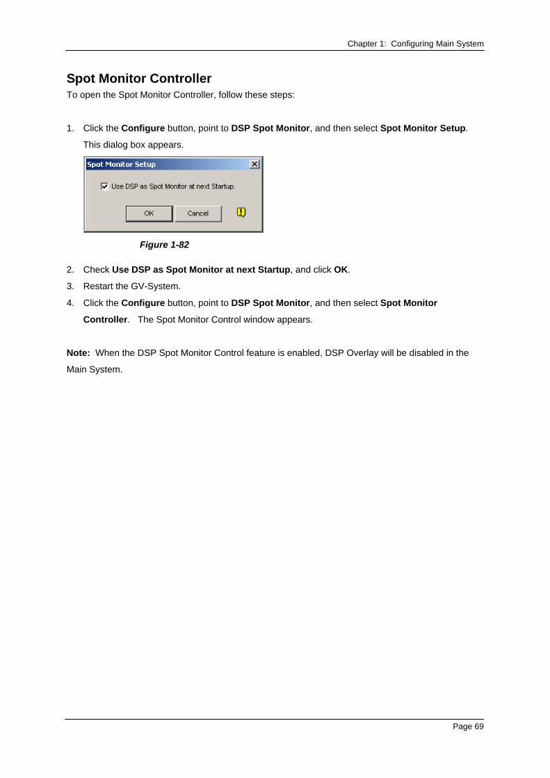
Chapter 1: Configuring Main System Spot Monitor Controller To open the Spot Monitor Controller, follow these steps:
1. Click the Configure button, point to DSP Spot Monitor, and then select Spot Monitor Setup.
This dialog box appears.
Figure 1-82
2. Check Use DSP as Spot Monitor at next Startup, and click OK.
3. Restart the GV-System.
4. Click the Configure button, point to DSP Spot Monitor, and then select Spot Monitor
Controller. The Spot Monitor Control window appears.
Note: When the DSP Spot Monitor Control feature is enabled, DSP Overlay will be disabled in the
Main System.
Page 69
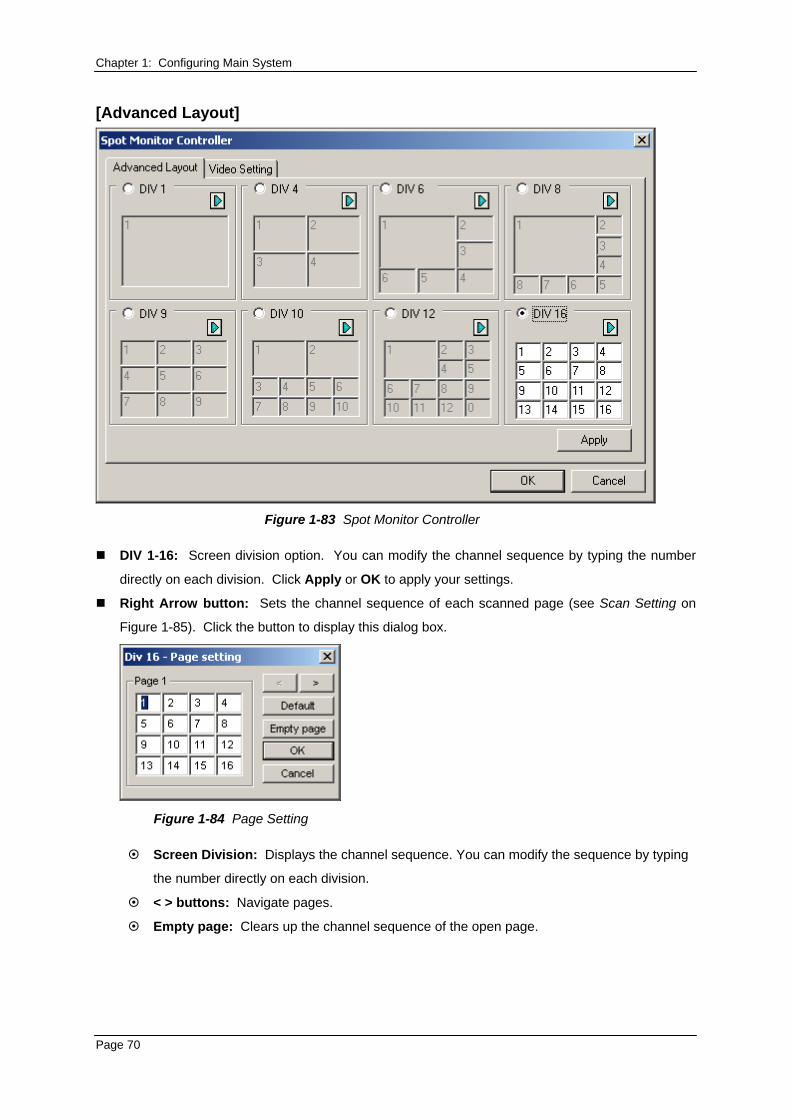
Chapter 1: Configuring Main System [Advanced Layout]
Figure 1-83 Spot Monitor Controller
DIV 1-16: Screen division option. You can modify the channel sequence by typing the number
directly on each division. Click Apply or OK to apply your settings.
Right Arrow button: Sets the channel sequence of each scanned page (see Scan Setting on
Figure 1-85). Click the button to display this dialog box.
Figure 1-84 Page Setting
Screen Division: Displays the channel sequence. You can modify the sequence by typing
the number directly on each division.
< > buttons: Navigate pages.
Empty page: Clears up the channel sequence of the open page.
Page 70
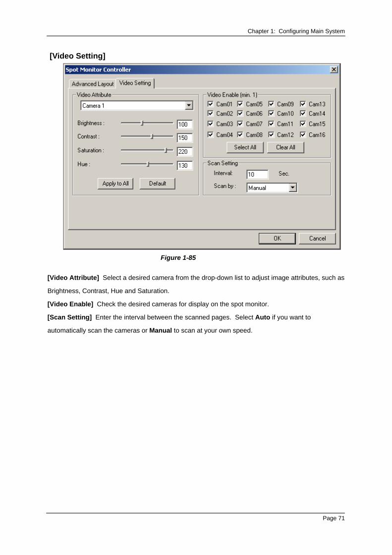
Chapter 1: Configuring Main System [Video Setting]
Figure 1-85
[Video Attribute] Select a desired camera from the drop-down list to adjust image attributes, such as
Brightness, Contrast, Hue and Saturation.
[Video Enable] Check the desired cameras for display on the spot monitor.
[Scan Setting] Enter the interval between the scanned pages. Select Auto if you want to
automatically scan the cameras or Manual to scan at your own speed.
Page 71
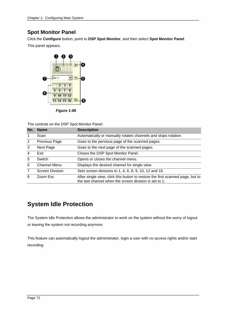
Chapter 1: Configuring Main System Spot Monitor Panel Click the Configure button, point to DSP Spot Monitor, and then select Spot Monitor Panel.
This panel appears.
1 3
4
57
6
2
8
Figure 1-86
The controls on the DSP Spot Monitor Panel: No. Name Description 1 Scan Automatically or manually rotates channels and stops rotation. 2 Previous Page Goes to the pervious page of the scanned pages. 3 Next Page Goes to the next page of the scanned pages. 4 Exit Closes the DSP Spot Monitor Panel. 5 Switch Opens or closes the channel menu. 6 Channel Menu Displays the desired channel for single view. 7 Screen Division Sets screen divisions to 1, 4, 6, 8, 9, 10, 12 and 16. 8 Zoom Esc After single view, click this button to restore the first scanned page, but to
the last channel when the screen division is set to 1.
System Idle Protection
The System Idle Protection allows the administrator to work on the system without the worry of logout
or leaving the system not recording anymore.
This feature can automatically logout the administrator, login a user with no access rights and/or start
recording.
Page 72
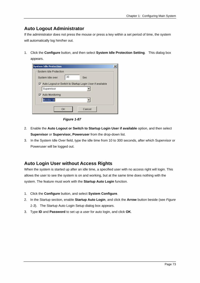
Chapter 1: Configuring Main System Auto Logout Administrator If the administrator does not press the mouse or press a key within a set period of time, the system
will automatically log him/her out.
1. Click the Configure button, and then select System Idle Protection Setting. This dialog box
appears.
Figure 1-87
2. Enable the Auto Logout or Switch to Startup Login User if available option, and then select
Supervisor or Supervisor, Poweruser from the drop-down list.
3. In the System Idle Over field, type the idle time from 10 to 300 seconds, after which Supervisor or
Poweruser will be logged out.
Auto Login User without Access Rights When the system is started up after an idle time, a specified user with no access right will login. This
allows the user to see the system is on and working, but at the same time does nothing with the
system. The feature must work with the Startup Auto Login function. 1. Click the Configure button, and select System Configure.
2. In the Startup section, enable Startup Auto Login, and click the Arrow button beside (see Figure
1-3). The Startup Auto Login Setup dialog box appears.
3. Type ID and Password to set up a user for auto login, and click OK.
Page 73
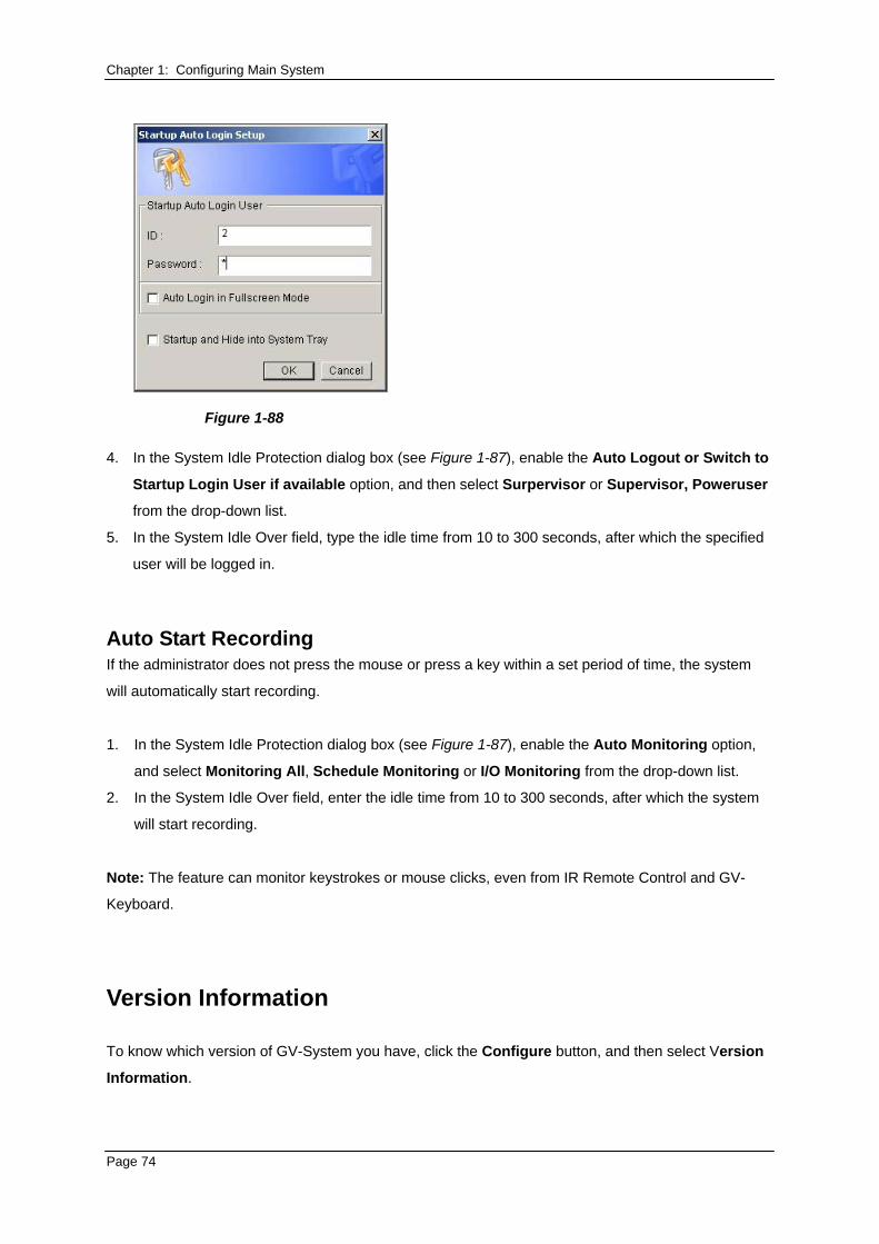
Chapter 1: Configuring Main System
Figure 1-88
4. In the System Idle Protection dialog box (see Figure 1-87), enable the Auto Logout or Switch to
Startup Login User if available option, and then select Surpervisor or Supervisor, Poweruser
from the drop-down list.
5. In the System Idle Over field, type the idle time from 10 to 300 seconds, after which the specified
user will be logged in.
Auto Start Recording If the administrator does not press the mouse or press a key within a set period of time, the system
will automatically start recording.
1. In the System Idle Protection dialog box (see Figure 1-87), enable the Auto Monitoring option,
and select Monitoring All, Schedule Monitoring or I/O Monitoring from the drop-down list.
2. In the System Idle Over field, enter the idle time from 10 to 300 seconds, after which the system
will start recording.
Note: The feature can monitor keystrokes or mouse clicks, even from IR Remote Control and GV-
Keyboard.
Version Information
To know which version of GV-System you have, click the Configure button, and then select Version
Information.
Page 74
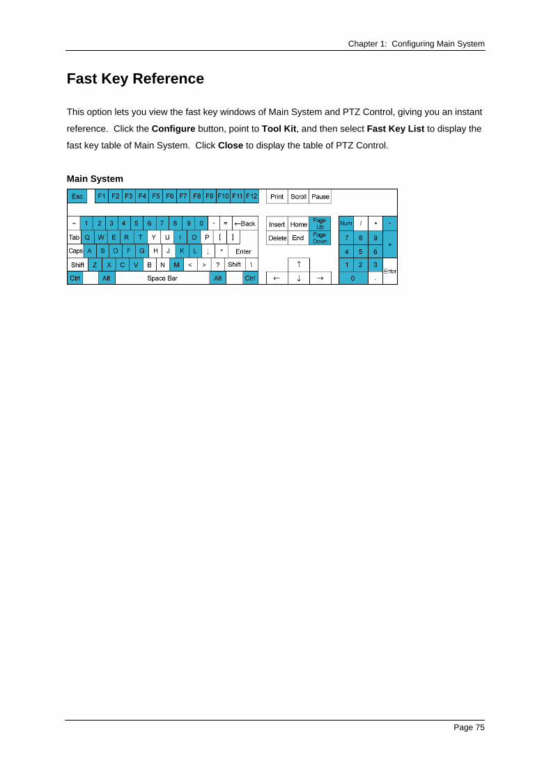
Chapter 1: Configuring Main System
Fast Key Reference
This option lets you view the fast key windows of Main System and PTZ Control, giving you an instant
reference. Click the Configure button, point to Tool Kit, and then select Fast Key List to display the
fast key table of Main System. Click Close to display the table of PTZ Control.
Main System
Page 75
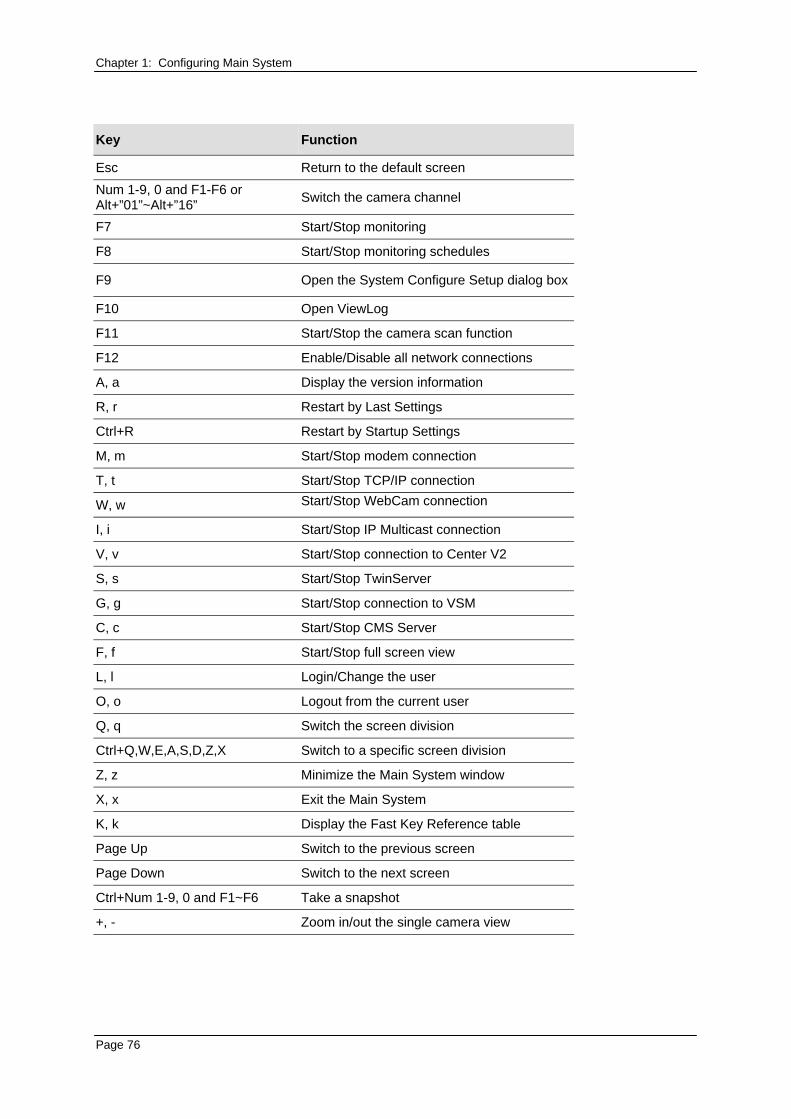
Chapter 1: Configuring Main System
Key Function
Esc Return to the default screen Num 1-9, 0 and F1-F6 or Alt+”01”~Alt+”16” Switch the camera channel
F7 Start/Stop monitoring
F8 Start/Stop monitoring schedules
F9 Open the System Configure Setup dialog box
F10 Open ViewLog
F11 Start/Stop the camera scan function
F12 Enable/Disable all network connections
A, a Display the version information
R, r Restart by Last Settings
Ctrl+R Restart by Startup Settings
M, m Start/Stop modem connection
T, t Start/Stop TCP/IP connection
W, w Start/Stop WebCam connection
I, i Start/Stop IP Multicast connection
V, v Start/Stop connection to Center V2
S, s Start/Stop TwinServer
G, g Start/Stop connection to VSM
C, c Start/Stop CMS Server
F, f Start/Stop full screen view
L, l Login/Change the user
O, o Logout from the current user
Q, q Switch the screen division
Ctrl+Q,W,E,A,S,D,Z,X Switch to a specific screen division
Z, z Minimize the Main System window
X, x Exit the Main System
K, k Display the Fast Key Reference table
Page Up Switch to the previous screen
Page Down Switch to the next screen
Ctrl+Num 1-9, 0 and F1~F6 Take a snapshot
+, - Zoom in/out the single camera view
Page 76
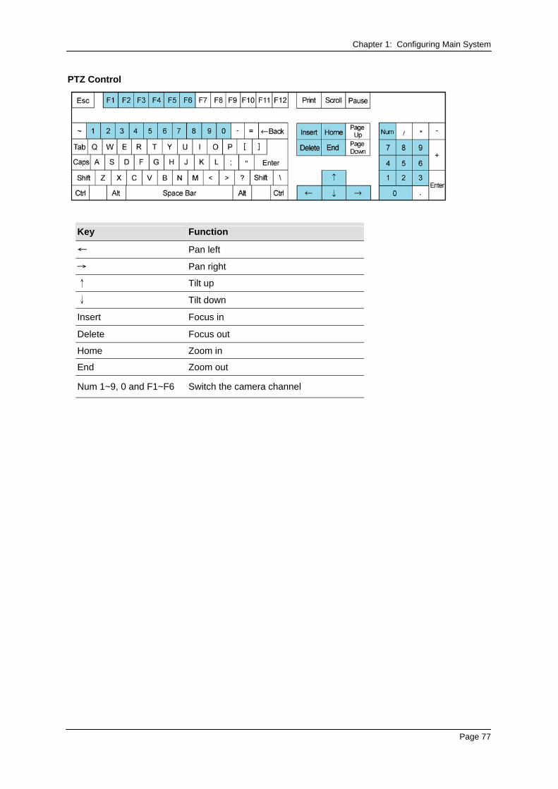
Chapter 1: Configuring Main System PTZ Control
Key Function
← Pan left
→ Pan right
↑ Tilt up
↓ Tilt down
Insert Focus in
Delete Focus out
Home Zoom in
End Zoom out
Num 1~9, 0 and F1~F6 Switch the camera channel
Page 77
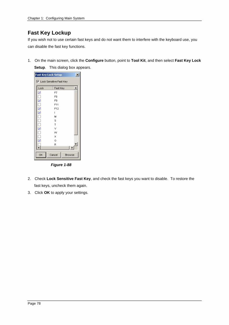
Chapter 1: Configuring Main System Fast Key Lockup If you wish not to use certain fast keys and do not want them to interfere with the keyboard use, you
can disable the fast key functions.
1. On the main screen, click the Configure button, point to Tool Kit, and then select Fast Key Lock
Setup. This dialog box appears.
Figure 1-88
2. Check Lock Sensitive Fast Key, and check the fast keys you want to disable. To restore the
fast keys, uncheck them again.
3. Click OK to apply your settings.
Page 78
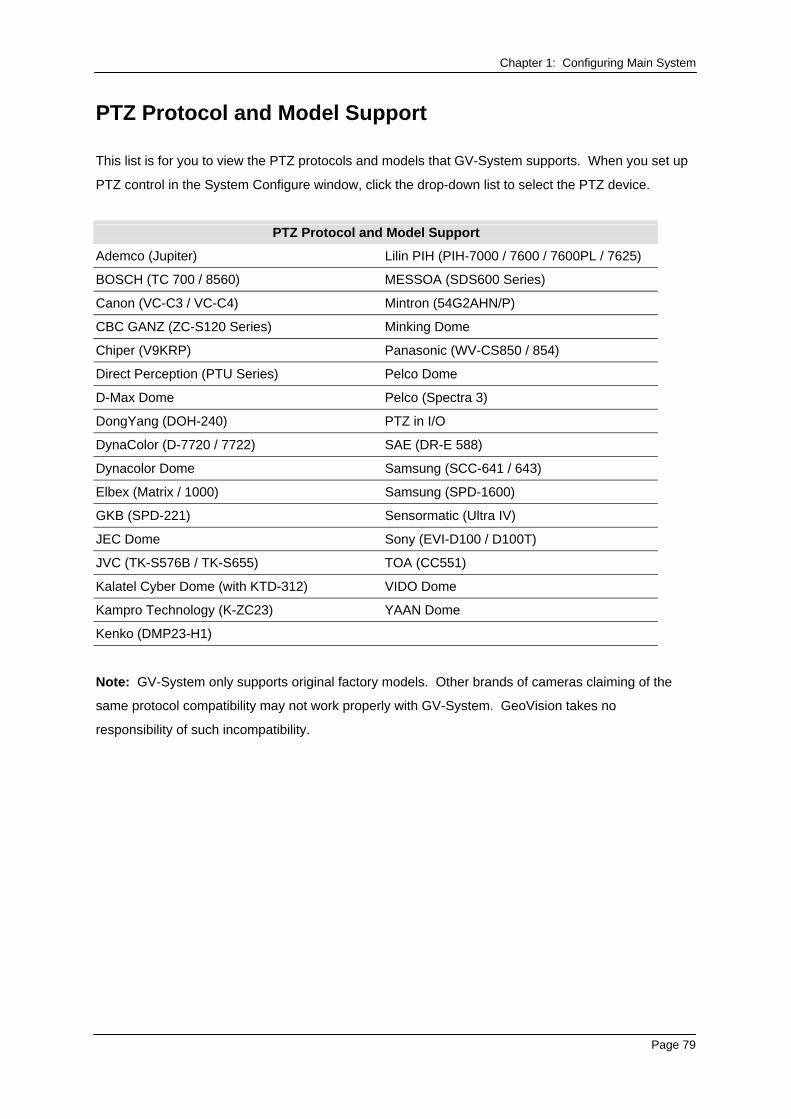
Chapter 1: Configuring Main System
PTZ Protocol and Model Support
This list is for you to view the PTZ protocols and models that GV-System supports. When you set up
PTZ control in the System Configure window, click the drop-down list to select the PTZ device.
PTZ Protocol and Model Support
Ademco (Jupiter) Lilin PIH (PIH-7000 / 7600 / 7600PL / 7625)
BOSCH (TC 700 / 8560) MESSOA (SDS600 Series)
Canon (VC-C3 / VC-C4) Mintron (54G2AHN/P)
CBC GANZ (ZC-S120 Series) Minking Dome
Chiper (V9KRP) Panasonic (WV-CS850 / 854)
Direct Perception (PTU Series) Pelco Dome
D-Max Dome Pelco (Spectra 3)
DongYang (DOH-240) PTZ in I/O
DynaColor (D-7720 / 7722) SAE (DR-E 588)
Dynacolor Dome Samsung (SCC-641 / 643)
Elbex (Matrix / 1000) Samsung (SPD-1600)
GKB (SPD-221) Sensormatic (Ultra IV)
JEC Dome Sony (EVI-D100 / D100T)
JVC (TK-S576B / TK-S655) TOA (CC551)
Kalatel Cyber Dome (with KTD-312) VIDO Dome
Kampro Technology (K-ZC23) YAAN Dome
Kenko (DMP23-H1)
Note: GV-System only supports original factory models. Other brands of cameras claiming of the
same protocol compatibility may not work properly with GV-System. GeoVision takes no
responsibility of such incompatibility.
Page 79