configuring sdh - cisco.com · sdh hierarchy sdh frame structure...
TRANSCRIPT
Configuring SDH
SDH is a standard that defines optical signals as well as a synchronous frame structure for multiplexed digitaltraffic. It is is used in Europe by the International Telecommunication Union TelecommunicationStandardization Sector (ITU-T). The SDH equipment is used everywhere except North America. The IMsupports the entire SDH hierarchy (except VC-2/C-2).
• Overview of SDH, page 1
• Services Provided by SDH Configuration, page 4
• SDH Multiplexing, page 7
• Restrictions for SDH, page 18
• Configuring Mediatype Controller, page 19
• Configuring Rate on SDH Ports, page 19
• SDH Line and Section Configuration Parameters, page 19
• Configuring BERT in SDH for SAToP, page 27
• SDH T1/E1 Configuration Parameters, page 30
• SDH T3/E3 Configuration Parameters, page 31
• SDH VC Configuration Parameters for SAToP, page 32
• Configuring ACR, page 33
• Configuring DCR, page 34
Overview of SDHSDH was defined by European Telecommunications Standards Institute (ETSI) and is now being controlledby the ITU-T standards body. SDH standard is prevalently used everywhere outside North America and Japan.
The following are true for SDH:
• Network Node Interface (NNI) defined by CCITT/ITU-TS for worldwide use and partly aompatiblewith SONET
1 port OC48/ 4 port OC12/OC3 + 12 port T1/E1 + 4 port T3/E3 CEM Interface Module Configuration Guide, Cisco IOSXE Fuji 16.7.x (ASR 920 Series Routers)
1
• One of the two options for the User-Network Interface (UNI) (the customer connection) and formallythe U reference point interface for support of BISDN
Basic SDH SignalThe basic format of an SDH signal allows it to carry many different services in its VC because SDH signalis bandwidth-flexible. This capability allows the transmission of high-speed packet-switched services, ATM,contribution video, and distribution video. However, SDH still permits transport and networking at the 2Mbit/s, 34 Mbit/s, and 140 Mbit/s levels, accommodating the existing digital hierarchy signals. In addition,SDH supports the transport of signals based on the 1.5 Mbit/s hierarchy.
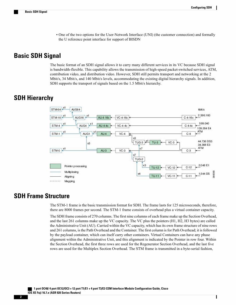
SDH Hierarchy
SDH Frame StructureThe STM-1 frame is the basic transmission format for SDH. The frame lasts for 125 microseconds, therefore,there are 8000 frames per second. The STM-1 frame consists of overhead plus a virtual container capacity.
The SDH frame consists of 270 columns. The first nine columns of each framemake up the Section Overhead,and the last 261 columns make up the VC capacity. The VC plus the pointers (H1, H2, H3 bytes) are calledthe Administrative Unit (AU). Carried within the VC capacity, which has its own frame structure of nine rowsand 261 columns, is the Path Overhead and the Container. The first column is for Path Overhead; it is followedby the payload container, which can itself carry other containers. Virtual Containers can have any phasealignment within the Administrative Unit, and this alignment is indicated by the Pointer in row four. Withinthe Section Overhead, the first three rows are used for the Regenerator Section Overhead, and the last fiverows are used for the Multiplex Section Overhead. The STM frame is transmitted in a byte-serial fashion,
1 port OC48/ 4 port OC12/OC3 + 12 port T1/E1 + 4 port T3/E3 CEM Interface Module Configuration Guide, CiscoIOS XE Fuji 16.7.x (ASR 920 Series Routers)
2
Configuring SDHBasic SDH Signal
row-by-row, and is scrambled immediately prior to transmission to ensure adequate clock timing content fordownstream regenerators.
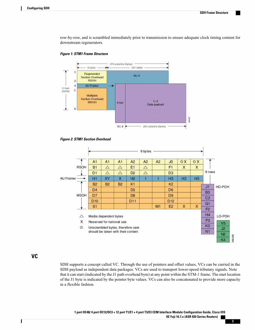
Figure 1: STM1 Frame Structure
Figure 2: STM1 Section Overhead
VCSDH supports a concept called VC. Through the use of pointers and offset values, VCs can be carried in theSDH payload as independent data packages. VCs are used to transport lower-speed tributary signals. Notethat it can start (indicated by the J1 path overhead byte) at any point within the STM-1 frame. The start locationof the J1 byte is indicated by the pointer byte values. VCs can also be concatenated to provide more capacityin a flexible fashion.
1 port OC48/ 4 port OC12/OC3 + 12 port T1/E1 + 4 port T3/E3 CEM Interface Module Configuration Guide, Cisco IOSXE Fuji 16.7.x (ASR 920 Series Routers)
3
Configuring SDHSDH Frame Structure
CEM OverviewCircuit Emulation (CEM) is a way to carry TDM circuits over packet switched network. CEM embeds theTDM circuits into packets, encapsulates them into an appropriate header, and then sends that through PacketSwitched Network. The receiver side of CEM restores the TDM circuits from packets.
Modes of CEM
• Structure Agnostic TDM over Packet (SAToP) (RFC 4553) – SAToP mode is used to encapsulateT1/E1 or T3/E3 unstructured (unchannelized) services over packet switched networks. In SAToP mode,the bytes are sent out as they arrive on the TDM line. Bytes do not have to be aligned with any framing.
In this mode, the interface is considered as a continuous framed bit stream. The packetization of thestream is done according to IETF RFC 4553. All signaling is carried transparently as a part of a bitstream.
• Circuit Emulation Service over Packet (CEP) (RFC 4842) - CEP mode is used to encapsulate SDHpayload envelopes (SPEs) like VC11, VC12, VC4, or VC4-Nc over PSN. In this mode, the bytes fromthe corresponding SPE are sent out as they arrive on the TDM line. The interface is considered as acontinuous framed bit stream. The packetization of the stream is done according to IETF RFC 4842.
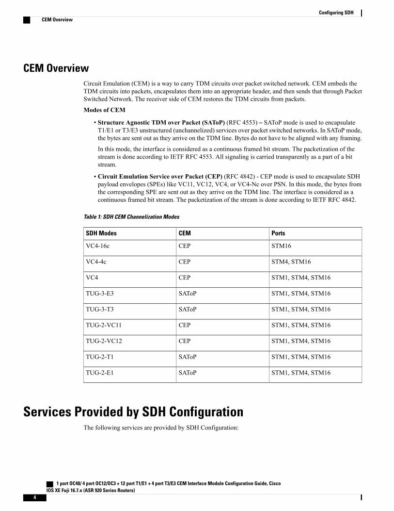
Table 1: SDH CEM Channelization Modes
PortsCEMSDH Modes
STM16CEPVC4-16c
STM4, STM16CEPVC4-4c
STM1, STM4, STM16CEPVC4
STM1, STM4, STM16SAToPTUG-3-E3
STM1, STM4, STM16SAToPTUG-3-T3
STM1, STM4, STM16CEPTUG-2-VC11
STM1, STM4, STM16CEPTUG-2-VC12
STM1, STM4, STM16SAToPTUG-2-T1
STM1, STM4, STM16SAToPTUG-2-E1
Services Provided by SDH ConfigurationThe following services are provided by SDH Configuration:
1 port OC48/ 4 port OC12/OC3 + 12 port T1/E1 + 4 port T3/E3 CEM Interface Module Configuration Guide, CiscoIOS XE Fuji 16.7.x (ASR 920 Series Routers)
4
Configuring SDHCEM Overview
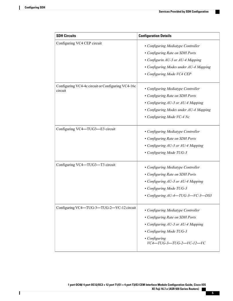
Configuration DetailsSDH Circuits
• Configuring Mediatype Controller
• Configuring Rate on SDH Ports
• Configurin AU-3 or AU-4 Mapping
• Configuring Modes under AU-4 Mapping
• Configuring Mode VC4 CEP
Configuring VC4 CEP circuit
• Configuring Mediatype Controller
• Configuring Rate on SDH Ports
• Configuring AU-3 or AU-4 Mapping
• Configuring Modes under AU-4 Mapping
• Configuring Mode VC-4 Nc
ConfiguringVC4-4c circuit or ConfiguringVC4-16ccircuit
• Configuring Mediatype Controller
• Configuring Rate on SDH Ports
• Configuring AU-3 or AU-4 Mapping
• Configuring Mode TUG-3
Configuring VC4—TUG3—E3 circuit
• Configuring Mediatype Controller
• Configuring Rate on SDH Ports
• Configuring AU-3 or AU-4 Mapping
• Configuring Mode TUG-3
• Configuring AU-4—TUG-3—VC-3—DS3
Configuring VC4—TUG3—T3 circuit
• Configuring Mediatype Controller
• Configuring Rate on SDH Ports
• Configuring AU-3 or AU-4 Mapping
• Configuring Mode TUG-3
• ConfiguringVC4—TUG-3—TUG-2—VC-12—VC
ConfiguringVC4—TUG-3—TUG-2—VC-12 circuit
1 port OC48/ 4 port OC12/OC3 + 12 port T1/E1 + 4 port T3/E3 CEM Interface Module Configuration Guide, Cisco IOSXE Fuji 16.7.x (ASR 920 Series Routers)
5
Configuring SDHServices Provided by SDH Configuration
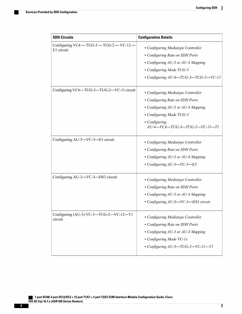
Configuration DetailsSDH Circuits
• Configuring Mediatype Controller
• Configuring Rate on SDH Ports
• Configuring AU-3 or AU-4 Mapping
• Configuring Mode TUG-3
• Configuring AU-4—TUG-3—TUG-2—VC-12
Configuring VC4— TUG-3— TUG-2—VC-12—E1 circuit
• Configuring Mediatype Controller
• Configuring Rate on SDH Ports
• Configuring AU-3 or AU-4 Mapping
• Configuring Mode TUG-3
• ConfiguringAU-4—VC4—TUG-3—TUG-2—VC-11—T1
ConfiguringVC4—TUG-3—TUG-2—VC-11 circuit
• Configuring Mediatype Controller
• Configuring Rate on SDH Ports
• Configuring AU-3 or AU-4 Mapping
• Configuring AU-3—VC-3—E3
Configuring AU-3—VC-3—E3 circuit
• Configuring Mediatype Controller
• Configuring Rate on SDH Ports
• Configuring AU-3 or AU-4 Mapping
• Configuring AU-3—VC-3—DS3 circuit
Configuring AU-3—VC-3—DS3 circuit
• Configuring Mediatype Controller
• Configuring Rate on SDH Ports
• Configuring AU-3 or AU-4 Mapping
• Configuring Mode VC-1x
• Configuring AU-3—TUG-2—VC-11—T1
Configuring (AU-3) VC-3—TUG-2—VC-12—T1circuit
1 port OC48/ 4 port OC12/OC3 + 12 port T1/E1 + 4 port T3/E3 CEM Interface Module Configuration Guide, CiscoIOS XE Fuji 16.7.x (ASR 920 Series Routers)
6
Configuring SDHServices Provided by SDH Configuration
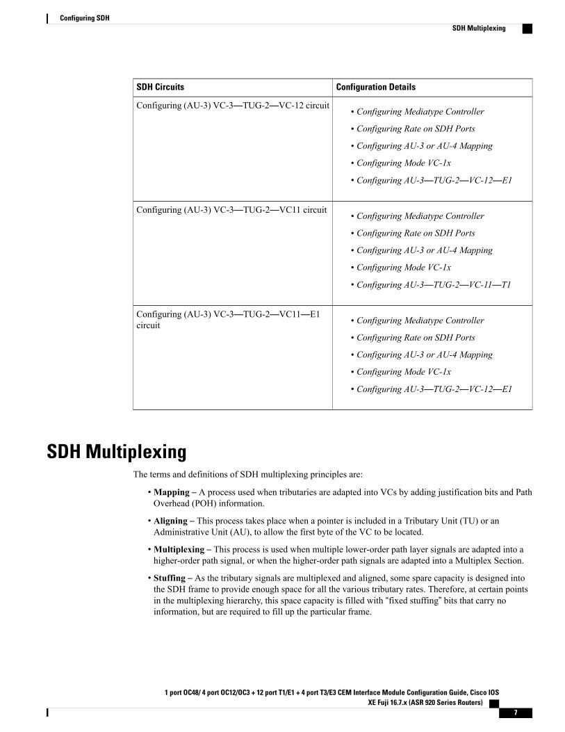
Configuration DetailsSDH Circuits
• Configuring Mediatype Controller
• Configuring Rate on SDH Ports
• Configuring AU-3 or AU-4 Mapping
• Configuring Mode VC-1x
• Configuring AU-3—TUG-2—VC-12—E1
Configuring (AU-3) VC-3—TUG-2—VC-12 circuit
• Configuring Mediatype Controller
• Configuring Rate on SDH Ports
• Configuring AU-3 or AU-4 Mapping
• Configuring Mode VC-1x
• Configuring AU-3—TUG-2—VC-11—T1
Configuring (AU-3) VC-3—TUG-2—VC11 circuit
• Configuring Mediatype Controller
• Configuring Rate on SDH Ports
• Configuring AU-3 or AU-4 Mapping
• Configuring Mode VC-1x
• Configuring AU-3—TUG-2—VC-12—E1
Configuring (AU-3) VC-3—TUG-2—VC11—E1circuit
SDH MultiplexingThe terms and definitions of SDH multiplexing principles are:
•Mapping – A process used when tributaries are adapted into VCs by adding justification bits and PathOverhead (POH) information.
• Aligning – This process takes place when a pointer is included in a Tributary Unit (TU) or anAdministrative Unit (AU), to allow the first byte of the VC to be located.
•Multiplexing – This process is used when multiple lower-order path layer signals are adapted into ahigher-order path signal, or when the higher-order path signals are adapted into a Multiplex Section.
• Stuffing – As the tributary signals are multiplexed and aligned, some spare capacity is designed intothe SDH frame to provide enough space for all the various tributary rates. Therefore, at certain pointsin the multiplexing hierarchy, this space capacity is filled with “fixed stuffing” bits that carry noinformation, but are required to fill up the particular frame.
1 port OC48/ 4 port OC12/OC3 + 12 port T1/E1 + 4 port T3/E3 CEM Interface Module Configuration Guide, Cisco IOSXE Fuji 16.7.x (ASR 920 Series Routers)
7
Configuring SDHSDH Multiplexing
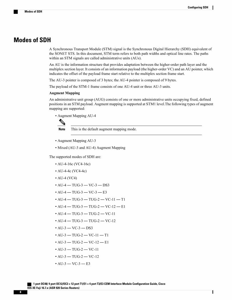
Modes of SDHA Synchronous Transport Module (STM) signal is the Synchronous Digital Hierarchy (SDH) equivalent ofthe SONET STS. In this document, STM term refers to both path widths and optical line rates. The pathswithin an STM signals are called administrative units (AUs).
An AU is the information structure that provides adaptation between the higher-order path layer and themultiplex section layer. It consists of an information payload (the higher-order VC) and an AU pointer, whichindicates the offset of the payload frame start relative to the multiplex section frame start.
The AU-3 pointer is composed of 3 bytes; the AU-4 pointer is composed of 9 bytes.
The payload of the STM-1 frame consists of one AU-4 unit or three AU-3 units.
Augment Mapping
An administrative unit group (AUG) consists of one or more administrative units occupying fixed, definedpositions in an STM payload. Augment mapping is supported at STM1 level.The following types of augmentmapping are supported:
• Augment Mapping AU-4
This is the default augment mapping mode.Note
• Augment Mapping AU-3
• Mixed (AU-3 and AU-4) Augment Mapping
The supported modes of SDH are:
• AU-4-16c (VC4-16c)
• AU-4-4c (VC4-4c)
• AU-4 (VC4)
• AU-4— TUG-3— VC-3— DS3
• AU-4— TUG-3— VC-3— E3
• AU-4— TUG-3— TUG-2— VC-11— T1
• AU-4— TUG-3— TUG-2— VC-12— E1
• AU-4— TUG-3— TUG-2— VC-11
• AU-4— TUG-3— TUG-2— VC-12
• AU-3— VC-3— DS3
• AU-3— TUG-2— VC-11— T1
• AU-3— TUG-2— VC-12— E1
• AU-3— TUG-2— VC-11
• AU-3— TUG-2— VC-12
• AU-3— VC-3— E3
1 port OC48/ 4 port OC12/OC3 + 12 port T1/E1 + 4 port T3/E3 CEM Interface Module Configuration Guide, CiscoIOS XE Fuji 16.7.x (ASR 920 Series Routers)
8
Configuring SDHModes of SDH
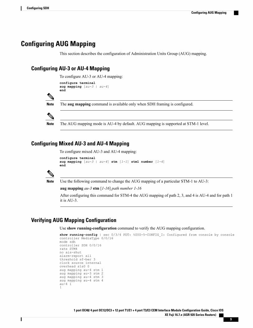
Configuring AUG MappingThis section describes the configuration of Administration Units Group (AUG) mapping.
Configuring AU-3 or AU-4 MappingTo configure AU-3 or AU-4 mapping:configure terminalaug mapping [au-3 | au-4]end
The aug mapping command is available only when SDH framing is configured.Note
The AUG mapping mode is AU-4 by default. AUG mapping is supported at STM-1 level.Note
Configuring Mixed AU-3 and AU-4 MappingTo configure mixed AU-3 and AU-4 mapping:configure terminalaug mapping [au-3 | au-4] stm [1-1] stm1 number [1-4]end
Use the following command to change the AUG mapping of a particular STM-1 to AU-3:
aug mapping au-3 stm [1-16] path number 1-16
After configuring this command for STM-4 the AUG mapping of path 2, 3, and 4 is AU-4 and for path 1it is AU-3.
Note
Verifying AUG Mapping ConfigurationUse show running-configuration command to verify the AUG mapping configuration.show running-config | sec 0/3/4 PDT: %SYS-5-CONFIG_I: Configured from console by consolecontroller MediaType 0/0/16mode sdhcontroller SDH 0/0/16rate STM4no ais-shutalarm-report allthreshold sf-ber 3clock source internaloverhead s1s0 0aug mapping au-4 stm 1aug mapping au-3 stm 2aug mapping au-4 stm 3aug mapping au-4 stm 4au-4 1!
1 port OC48/ 4 port OC12/OC3 + 12 port T1/E1 + 4 port T3/E3 CEM Interface Module Configuration Guide, Cisco IOSXE Fuji 16.7.x (ASR 920 Series Routers)
9
Configuring SDHConfiguring AUG Mapping
au-3 4!au-3 5!au-3 6!au-4 3!au-4 4!
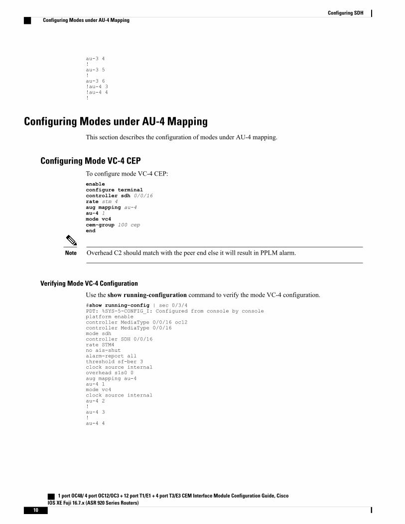
Configuring Modes under AU-4 MappingThis section describes the configuration of modes under AU-4 mapping.
Configuring Mode VC-4 CEPTo configure mode VC-4 CEP:enableconfigure terminalcontroller sdh 0/0/16rate stm 4aug mapping au-4au-4 1mode vc4cem-group 100 cepend
Overhead C2 should match with the peer end else it will result in PPLM alarm.Note
Verifying Mode VC-4 Configuration
Use the show running-configuration command to verify the mode VC-4 configuration.#show running-config | sec 0/3/4PDT: %SYS-5-CONFIG_I: Configured from console by consoleplatform enablecontroller MediaType 0/0/16 oc12controller MediaType 0/0/16mode sdhcontroller SDH 0/0/16rate STM4no ais-shutalarm-report allthreshold sf-ber 3clock source internaloverhead s1s0 0aug mapping au-4au-4 1mode vc4clock source internalau-4 2!au-4 3!au-4 4
1 port OC48/ 4 port OC12/OC3 + 12 port T1/E1 + 4 port T3/E3 CEM Interface Module Configuration Guide, CiscoIOS XE Fuji 16.7.x (ASR 920 Series Routers)
10
Configuring SDHConfiguring Modes under AU-4 Mapping
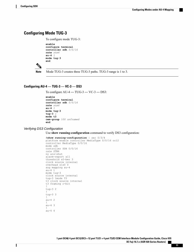
Configuring Mode TUG-3To configure mode TUG-3:enableconfigure terminalcontroller sdh 0/0/16rate stm4au-4 1mode tug-3end
Mode TUG-3 creates three TUG-3 paths. TUG-3 range is 1 to 3.Note
Configuring AU-4 — TUG-3 — VC-3 — DS3
To configure AU-4— TUG-3— VC-3— DS3:enableconfigure terminalcontroller sdh 0/0/16rate stm4au-4 1mode tug-3tug-3 1mode t3cem-group 100 unframedend
Verifying DS3 ConfigurationUse show running-configuration command to verify DS3 configuration:#show running-configuration | sec 0/3/4platform enable controller MediaType 0/0/16 oc12controller MediaType 0/0/16mode sdhcontroller SDH 0/0/16rate STM4no ais-shutalarm-report allthreshold sf-ber 3clock source internaloverhead s1s0 0aug mapping au-4au-4 1mode tug-3clock source internaltug-3 1mode T3t3 clock source internalt3 framing c-bit!tug-3 2!tug-3 3!au-4 2!au-4 3!au-4 4
1 port OC48/ 4 port OC12/OC3 + 12 port T1/E1 + 4 port T3/E3 CEM Interface Module Configuration Guide, Cisco IOSXE Fuji 16.7.x (ASR 920 Series Routers)
11
Configuring SDHConfiguring Modes under AU-4 Mapping
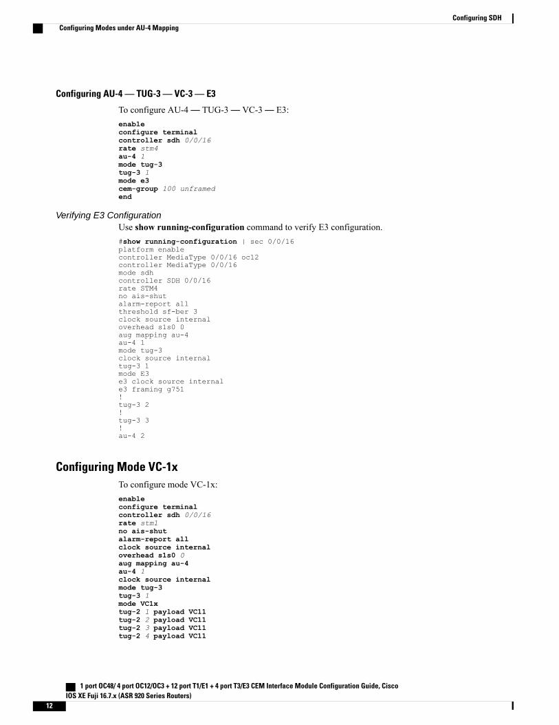
Configuring AU-4 — TUG-3 — VC-3 — E3
To configure AU-4— TUG-3— VC-3— E3:enableconfigure terminalcontroller sdh 0/0/16rate stm4au-4 1mode tug-3tug-3 1mode e3cem-group 100 unframedend
Verifying E3 ConfigurationUse show running-configuration command to verify E3 configuration.#show running-configuration | sec 0/0/16platform enablecontroller MediaType 0/0/16 oc12controller MediaType 0/0/16mode sdhcontroller SDH 0/0/16rate STM4no ais-shutalarm-report allthreshold sf-ber 3clock source internaloverhead s1s0 0aug mapping au-4au-4 1mode tug-3clock source internaltug-3 1mode E3e3 clock source internale3 framing g751!tug-3 2!tug-3 3!au-4 2
Configuring Mode VC-1xTo configure mode VC-1x:enableconfigure terminalcontroller sdh 0/0/16rate stm1no ais-shutalarm-report allclock source internaloverhead s1s0 0aug mapping au-4au-4 1clock source internalmode tug-3tug-3 1mode VC1xtug-2 1 payload VC11tug-2 2 payload VC11tug-2 3 payload VC11tug-2 4 payload VC11
1 port OC48/ 4 port OC12/OC3 + 12 port T1/E1 + 4 port T3/E3 CEM Interface Module Configuration Guide, CiscoIOS XE Fuji 16.7.x (ASR 920 Series Routers)
12
Configuring SDHConfiguring Modes under AU-4 Mapping
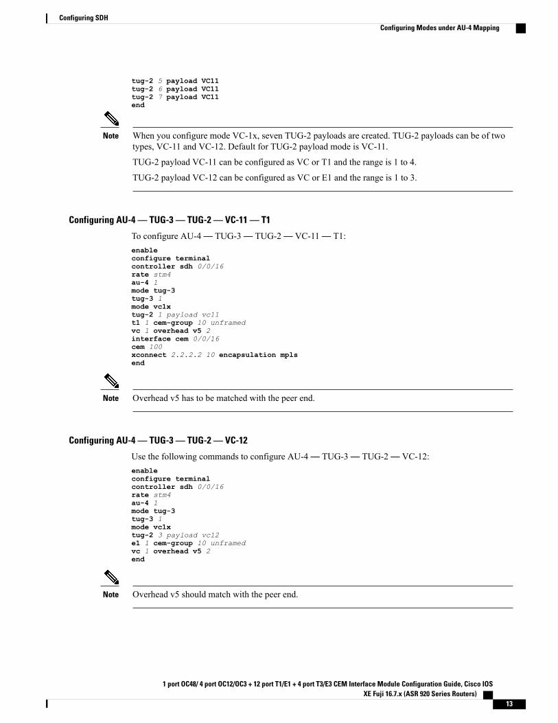
tug-2 5 payload VC11tug-2 6 payload VC11tug-2 7 payload VC11end
When you configure mode VC-1x, seven TUG-2 payloads are created. TUG-2 payloads can be of twotypes, VC-11 and VC-12. Default for TUG-2 payload mode is VC-11.
TUG-2 payload VC-11 can be configured as VC or T1 and the range is 1 to 4.
TUG-2 payload VC-12 can be configured as VC or E1 and the range is 1 to 3.
Note
Configuring AU-4 — TUG-3 — TUG-2 — VC-11 — T1
To configure AU-4— TUG-3— TUG-2— VC-11— T1:enableconfigure terminalcontroller sdh 0/0/16rate stm4au-4 1mode tug-3tug-3 1mode vc1xtug-2 1 payload vc11t1 1 cem-group 10 unframedvc 1 overhead v5 2interface cem 0/0/16cem 100xconnect 2.2.2.2 10 encapsulation mplsend
Overhead v5 has to be matched with the peer end.Note
Configuring AU-4 — TUG-3 — TUG-2 — VC-12
Use the following commands to configure AU-4— TUG-3— TUG-2— VC-12:enableconfigure terminalcontroller sdh 0/0/16rate stm4au-4 1mode tug-3tug-3 1mode vc1xtug-2 3 payload vc12e1 1 cem-group 10 unframedvc 1 overhead v5 2end
Overhead v5 should match with the peer end.Note
1 port OC48/ 4 port OC12/OC3 + 12 port T1/E1 + 4 port T3/E3 CEM Interface Module Configuration Guide, Cisco IOSXE Fuji 16.7.x (ASR 920 Series Routers)
13
Configuring SDHConfiguring Modes under AU-4 Mapping
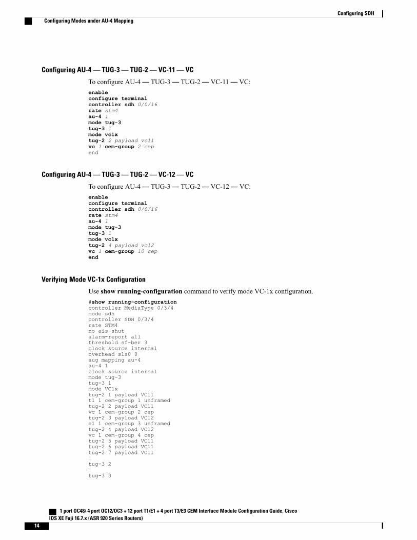
Configuring AU-4 — TUG-3 — TUG-2 — VC-11 — VC
To configure AU-4— TUG-3— TUG-2— VC-11— VC:enableconfigure terminalcontroller sdh 0/0/16rate stm4au-4 1mode tug-3tug-3 1mode vc1xtug-2 2 payload vc11vc 1 cem-group 2 cepend
Configuring AU-4 — TUG-3 — TUG-2 — VC-12 — VC
To configure AU-4— TUG-3— TUG-2— VC-12— VC:enableconfigure terminalcontroller sdh 0/0/16rate stm4au-4 1mode tug-3tug-3 1mode vc1xtug-2 4 payload vc12vc 1 cem-group 10 cepend
Verifying Mode VC-1x Configuration
Use show running-configuration command to verify mode VC-1x configuration.#show running-configurationcontroller MediaType 0/3/4mode sdhcontroller SDH 0/3/4rate STM4no ais-shutalarm-report allthreshold sf-ber 3clock source internaloverhead s1s0 0aug mapping au-4au-4 1clock source internalmode tug-3tug-3 1mode VC1xtug-2 1 payload VC11t1 1 cem-group 1 unframedtug-2 2 payload VC11vc 1 cem-group 2 ceptug-2 3 payload VC12e1 1 cem-group 3 unframedtug-2 4 payload VC12vc 1 cem-group 4 ceptug-2 5 payload VC11tug-2 6 payload VC11tug-2 7 payload VC11!tug-3 2!tug-3 3
1 port OC48/ 4 port OC12/OC3 + 12 port T1/E1 + 4 port T3/E3 CEM Interface Module Configuration Guide, CiscoIOS XE Fuji 16.7.x (ASR 920 Series Routers)
14
Configuring SDHConfiguring Modes under AU-4 Mapping
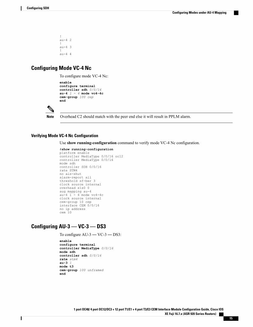
!au-4 2!au-4 3!au-4 4
Configuring Mode VC-4 NcTo configure mode VC-4 Nc:enableconfigure terminalcontroller sdh 0/0/16au-4 1 - 4 mode vc4-4ccem-group 100 cepend
Overhead C2 should match with the peer end else it will result in PPLM alarm.Note
Verifying Mode VC-4 Nc Configuration
Use show running-configuration command to verify mode VC-4 Nc configuration.#show running-configurationplatform enablecontroller MediaType 0/0/16 oc12controller MediaType 0/0/16mode sdhcontroller SDH 0/0/16rate STM4no ais-shutalarm-report allthreshold sf-ber 3clock source internaloverhead s1s0 0aug mapping au-4au-4 1 - 4 mode vc4-4cclock source internalcem-group 10 cepinterface CEM 0/0/16no ip addresscem 10
Configuring AU-3 — VC-3 — DS3To configure AU-3— VC-3— DS3:enableconfigure terminalcontroller MediaType 0/0/16mode sdhcontroller sdh 0/0/16rate stm4au-3 1mode t3cem-group 100 unframedend
1 port OC48/ 4 port OC12/OC3 + 12 port T1/E1 + 4 port T3/E3 CEM Interface Module Configuration Guide, Cisco IOSXE Fuji 16.7.x (ASR 920 Series Routers)
15
Configuring SDHConfiguring Modes under AU-4 Mapping
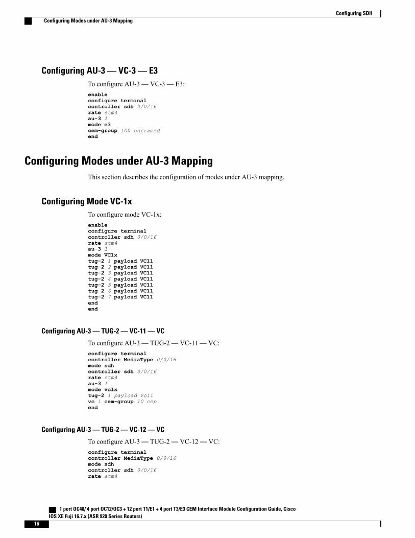
Configuring AU-3 — VC-3 — E3To configure AU-3— VC-3— E3:enableconfigure terminalcontroller sdh 0/0/16rate stm4au-3 1mode e3cem-group 100 unframedend
Configuring Modes under AU-3 MappingThis section describes the configuration of modes under AU-3 mapping.
Configuring Mode VC-1xTo configure mode VC-1x:enableconfigure terminalcontroller sdh 0/0/16rate stm4au-3 1mode VC1xtug-2 1 payload VC11tug-2 2 payload VC11tug-2 3 payload VC11tug-2 4 payload VC11tug-2 5 payload VC11tug-2 6 payload VC11tug-2 7 payload VC11endend
Configuring AU-3 — TUG-2 — VC-11 — VC
To configure AU-3— TUG-2— VC-11— VC:configure terminalcontroller MediaType 0/0/16mode sdhcontroller sdh 0/0/16rate stm4au-3 1mode vc1xtug-2 1 payload vc11vc 1 cem-group 10 cepend
Configuring AU-3 — TUG-2 — VC-12 — VC
To configure AU-3— TUG-2— VC-12— VC:configure terminalcontroller MediaType 0/0/16mode sdhcontroller sdh 0/0/16rate stm4
1 port OC48/ 4 port OC12/OC3 + 12 port T1/E1 + 4 port T3/E3 CEM Interface Module Configuration Guide, CiscoIOS XE Fuji 16.7.x (ASR 920 Series Routers)
16
Configuring SDHConfiguring Modes under AU-3 Mapping
au-3 1mode vc1xtug-2 1 payload vc12vc 1 cem-group 10 cepend
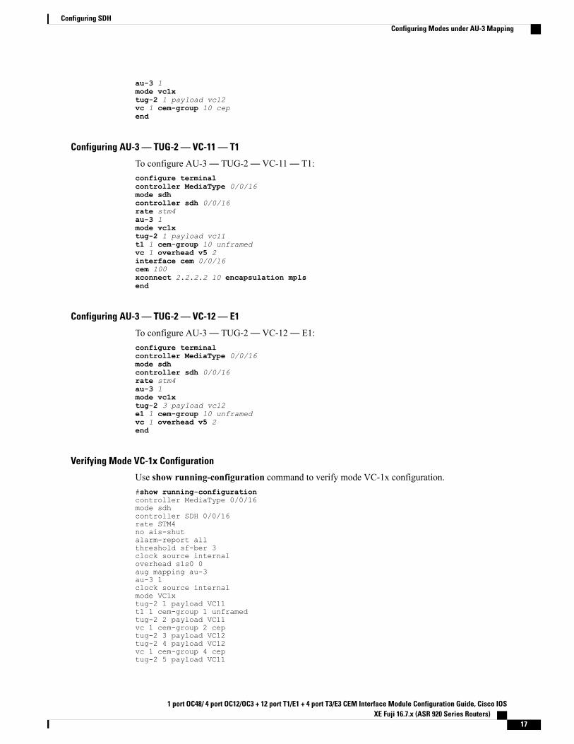
Configuring AU-3 — TUG-2 — VC-11 — T1
To configure AU-3— TUG-2— VC-11— T1:configure terminalcontroller MediaType 0/0/16mode sdhcontroller sdh 0/0/16rate stm4au-3 1mode vc1xtug-2 1 payload vc11t1 1 cem-group 10 unframedvc 1 overhead v5 2interface cem 0/0/16cem 100xconnect 2.2.2.2 10 encapsulation mplsend
Configuring AU-3 — TUG-2 — VC-12 — E1
To configure AU-3— TUG-2— VC-12— E1:configure terminalcontroller MediaType 0/0/16mode sdhcontroller sdh 0/0/16rate stm4au-3 1mode vc1xtug-2 3 payload vc12e1 1 cem-group 10 unframedvc 1 overhead v5 2end
Verifying Mode VC-1x Configuration
Use show running-configuration command to verify mode VC-1x configuration.#show running-configurationcontroller MediaType 0/0/16mode sdhcontroller SDH 0/0/16rate STM4no ais-shutalarm-report allthreshold sf-ber 3clock source internaloverhead s1s0 0aug mapping au-3au-3 1clock source internalmode VC1xtug-2 1 payload VC11t1 1 cem-group 1 unframedtug-2 2 payload VC11vc 1 cem-group 2 ceptug-2 3 payload VC12tug-2 4 payload VC12vc 1 cem-group 4 ceptug-2 5 payload VC11
1 port OC48/ 4 port OC12/OC3 + 12 port T1/E1 + 4 port T3/E3 CEM Interface Module Configuration Guide, Cisco IOSXE Fuji 16.7.x (ASR 920 Series Routers)
17
Configuring SDHConfiguring Modes under AU-3 Mapping
tug-2 6 payload VC11tug-2 7 payload VC11
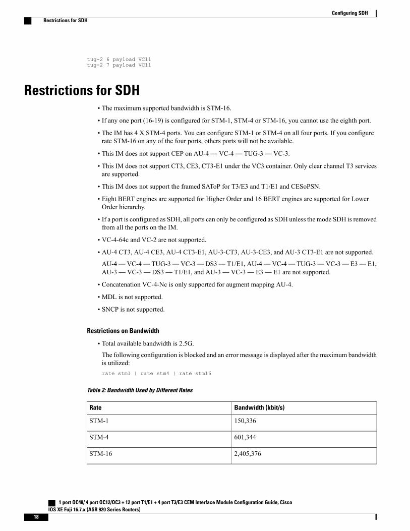
Restrictions for SDH• The maximum supported bandwidth is STM-16.
• If any one port (16-19) is configured for STM-1, STM-4 or STM-16, you cannot use the eighth port.
• The IM has 4 X STM-4 ports. You can configure STM-1 or STM-4 on all four ports. If you configurerate STM-16 on any of the four ports, others ports will not be available.
• This IM does not support CEP on AU-4— VC-4— TUG-3— VC-3.
• This IM does not support CT3, CE3, CT3-E1 under the VC3 container. Only clear channel T3 servicesare supported.
• This IM does not support the framed SAToP for T3/E3 and T1/E1 and CESoPSN.
• Eight BERT engines are supported for Higher Order and 16 BERT engines are supported for LowerOrder hierarchy.
• If a port is configured as SDH, all ports can only be configured as SDH unless the mode SDH is removedfrom all the ports on the IM.
• VC-4-64c and VC-2 are not supported.
• AU-4 CT3, AU-4 CE3, AU-4 CT3-E1, AU-3-CT3, AU-3-CE3, and AU-3 CT3-E1 are not supported.AU-4— VC-4— TUG-3— VC-3— DS3— T1/E1, AU-4— VC-4— TUG-3— VC-3— E3— E1,AU-3— VC-3— DS3— T1/E1, and AU-3— VC-3— E3— E1 are not supported.
• Concatenation VC-4-Nc is only supported for augment mapping AU-4.
• MDL is not supported.
• SNCP is not supported.
Restrictions on Bandwidth
• Total available bandwidth is 2.5G.The following configuration is blocked and an error message is displayed after the maximum bandwidthis utilized:rate stm1 | rate stm4 | rate stm16
Table 2: Bandwidth Used by Different Rates
Bandwidth (kbit/s)Rate
150,336STM-1
601,344STM-4
2,405,376STM-16
1 port OC48/ 4 port OC12/OC3 + 12 port T1/E1 + 4 port T3/E3 CEM Interface Module Configuration Guide, CiscoIOS XE Fuji 16.7.x (ASR 920 Series Routers)
18
Configuring SDHRestrictions for SDH
Restrictions for Scale PW Circuits
• Only 1000 CEM PW Circuits per OCN Interface modules are supported.
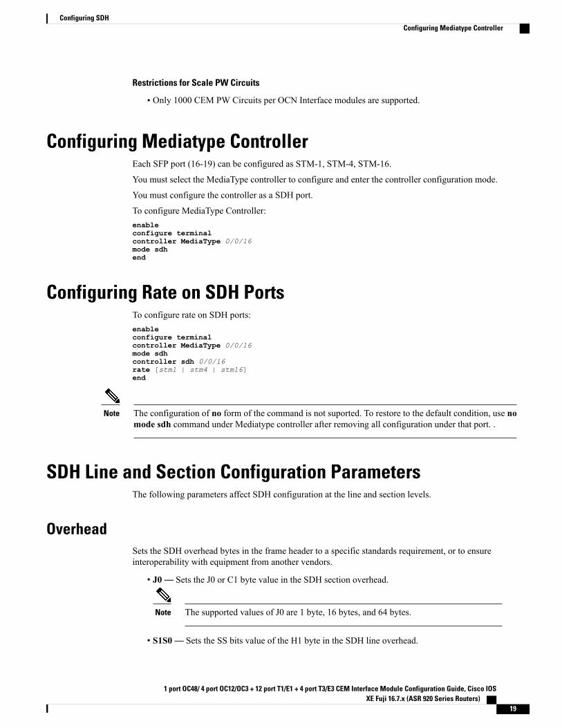
Configuring Mediatype ControllerEach SFP port (16-19) can be configured as STM-1, STM-4, STM-16.
You must select the MediaType controller to configure and enter the controller configuration mode.
You must configure the controller as a SDH port.
To configure MediaType Controller:enableconfigure terminalcontroller MediaType 0/0/16mode sdhend
Configuring Rate on SDH PortsTo configure rate on SDH ports:enableconfigure terminalcontroller MediaType 0/0/16mode sdhcontroller sdh 0/0/16rate [stm1 | stm4 | stm16]end
The configuration of no form of the command is not suported. To restore to the default condition, use nomode sdh command under Mediatype controller after removing all configuration under that port. .
Note
SDH Line and Section Configuration ParametersThe following parameters affect SDH configuration at the line and section levels.
OverheadSets the SDH overhead bytes in the frame header to a specific standards requirement, or to ensureinteroperability with equipment from another vendors.
• J0— Sets the J0 or C1 byte value in the SDH section overhead.
The supported values of J0 are 1 byte, 16 bytes, and 64 bytes.Note
• S1S0— Sets the SS bits value of the H1 byte in the SDH line overhead.
1 port OC48/ 4 port OC12/OC3 + 12 port T1/E1 + 4 port T3/E3 CEM Interface Module Configuration Guide, Cisco IOSXE Fuji 16.7.x (ASR 920 Series Routers)
19
Configuring SDHConfiguring Mediatype Controller
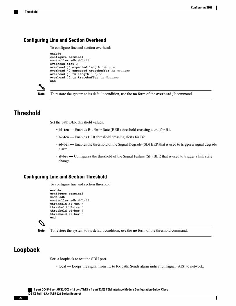
Configuring Line and Section OverheadTo configure line and section overhead:enableconfigure terminalcontroller sdh 0/0/16overhead s1s0 2overhead j0 expected length 16-byteoverhead j0 expected tracebuffer rx Messageoverhead j0 tx length 1-byteoverhead j0 tx tracebuffer tx Messageend
To restore the system to its default condition, use the no form of the overhead j0 command.Note
ThresholdSet the path BER threshold values.
• b1-tca— Enables Bit Error Rate (BER) threshold crossing alerts for B1.
• b2-tca— Enables BER threshold crossing alerts for B2.
• sd-ber— Enables the threshold of the Signal Degrade (SD) BER that is used to trigger a signal degradealarm.
• sf-ber— Configures the threshold of the Signal Failure (SF) BER that is used to trigger a link statechange.
Configuring Line and Section ThresholdTo configure line and section threshold:enableconfigure terminalmode sdhcontroller sdh 0/0/16threshold b1-tca 5threshold b2-tca 5threshold sd-ber 5threshold sf-ber 5end
To restore the system to its default condition, use the no form of the threshold command.Note
LoopbackSets a loopback to test the SDH port.
• local— Loops the signal from Tx to Rx path. Sends alarm indication signal (AIS) to network.
1 port OC48/ 4 port OC12/OC3 + 12 port T1/E1 + 4 port T3/E3 CEM Interface Module Configuration Guide, CiscoIOS XE Fuji 16.7.x (ASR 920 Series Routers)
20
Configuring SDHThreshold
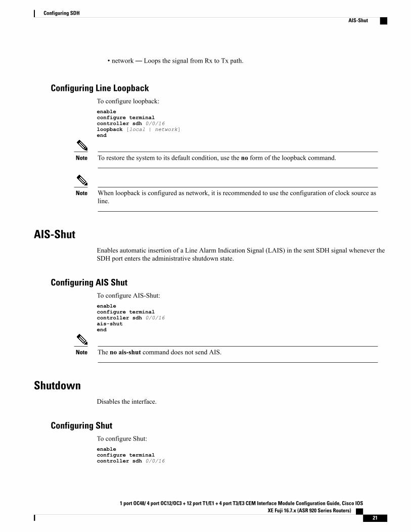
• network— Loops the signal from Rx to Tx path.
Configuring Line LoopbackTo configure loopback:enableconfigure terminalcontroller sdh 0/0/16loopback [local | network]end
To restore the system to its default condition, use the no form of the loopback command.Note
When loopback is configured as network, it is recommended to use the configuration of clock source asline.
Note
AIS-ShutEnables automatic insertion of a Line Alarm Indication Signal (LAIS) in the sent SDH signal whenever theSDH port enters the administrative shutdown state.
Configuring AIS ShutTo configure AIS-Shut:enableconfigure terminalcontroller sdh 0/0/16ais-shutend
The no ais-shut command does not send AIS.Note
ShutdownDisables the interface.
Configuring ShutTo configure Shut:enableconfigure terminalcontroller sdh 0/0/16
1 port OC48/ 4 port OC12/OC3 + 12 port T1/E1 + 4 port T3/E3 CEM Interface Module Configuration Guide, Cisco IOSXE Fuji 16.7.x (ASR 920 Series Routers)
21
Configuring SDHAIS-Shut
shutdownend
Use the no shutdown command to disable the interface.Note
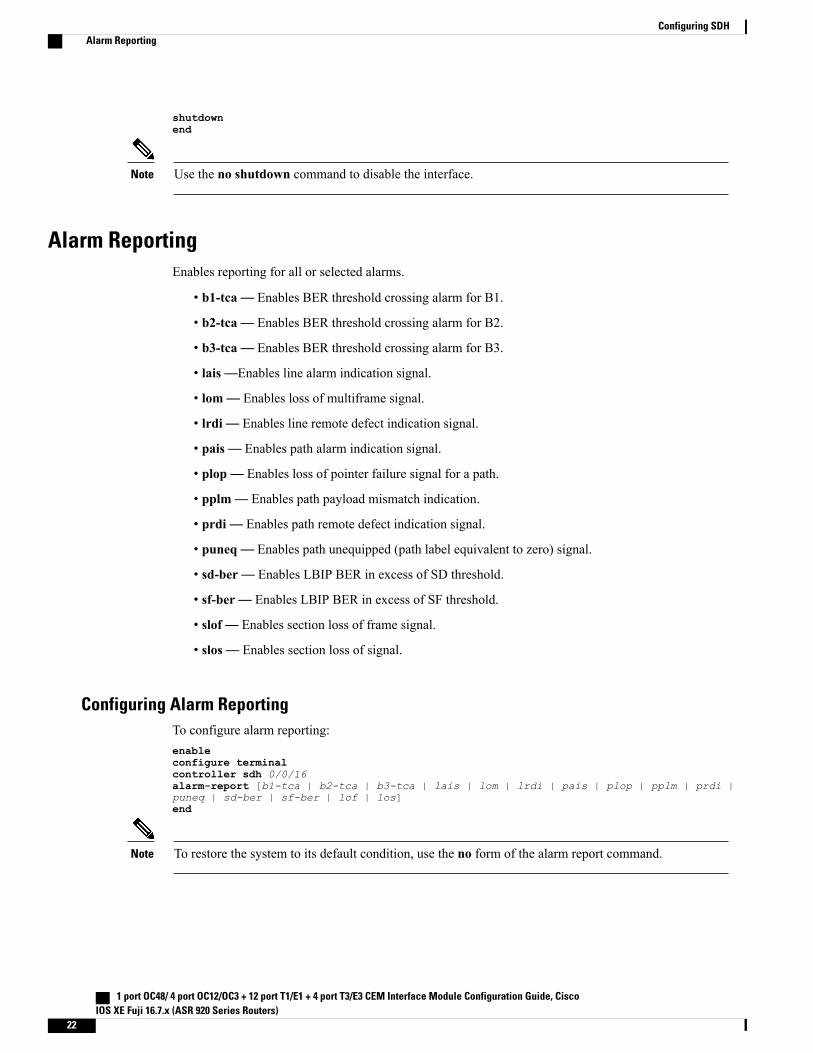
Alarm ReportingEnables reporting for all or selected alarms.
• b1-tca— Enables BER threshold crossing alarm for B1.
• b2-tca— Enables BER threshold crossing alarm for B2.
• b3-tca— Enables BER threshold crossing alarm for B3.
• lais—Enables line alarm indication signal.
• lom— Enables loss of multiframe signal.
• lrdi— Enables line remote defect indication signal.
• pais— Enables path alarm indication signal.
• plop— Enables loss of pointer failure signal for a path.
• pplm— Enables path payload mismatch indication.
• prdi— Enables path remote defect indication signal.
• puneq— Enables path unequipped (path label equivalent to zero) signal.
• sd-ber— Enables LBIP BER in excess of SD threshold.
• sf-ber— Enables LBIP BER in excess of SF threshold.
• slof— Enables section loss of frame signal.
• slos— Enables section loss of signal.
Configuring Alarm ReportingTo configure alarm reporting:enableconfigure terminalcontroller sdh 0/0/16alarm-report [b1-tca | b2-tca | b3-tca | lais | lom | lrdi | pais | plop | pplm | prdi |puneq | sd-ber | sf-ber | lof | los]end
To restore the system to its default condition, use the no form of the alarm report command.Note
1 port OC48/ 4 port OC12/OC3 + 12 port T1/E1 + 4 port T3/E3 CEM Interface Module Configuration Guide, CiscoIOS XE Fuji 16.7.x (ASR 920 Series Routers)
22
Configuring SDHAlarm Reporting
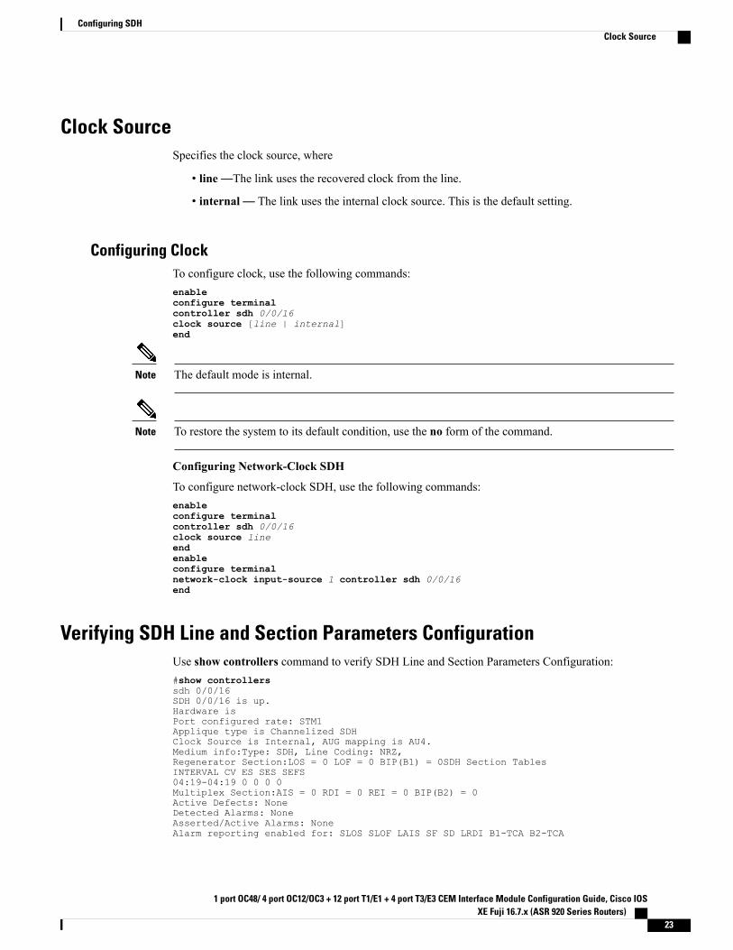
Clock SourceSpecifies the clock source, where
• line—The link uses the recovered clock from the line.
• internal— The link uses the internal clock source. This is the default setting.
Configuring ClockTo configure clock, use the following commands:enableconfigure terminalcontroller sdh 0/0/16clock source [line | internal]end
The default mode is internal.Note
To restore the system to its default condition, use the no form of the command.Note
Configuring Network-Clock SDH
To configure network-clock SDH, use the following commands:enableconfigure terminalcontroller sdh 0/0/16clock source lineendenableconfigure terminalnetwork-clock input-source 1 controller sdh 0/0/16end
Verifying SDH Line and Section Parameters ConfigurationUse show controllers command to verify SDH Line and Section Parameters Configuration:#show controllerssdh 0/0/16SDH 0/0/16 is up.Hardware isPort configured rate: STM1Applique type is Channelized SDHClock Source is Internal, AUG mapping is AU4.Medium info:Type: SDH, Line Coding: NRZ,Regenerator Section:LOS = 0 LOF = 0 BIP(B1) = 0SDH Section TablesINTERVAL CV ES SES SEFS04:19-04:19 0 0 0 0Multiplex Section:AIS = 0 RDI = 0 REI = 0 BIP(B2) = 0Active Defects: NoneDetected Alarms: NoneAsserted/Active Alarms: NoneAlarm reporting enabled for: SLOS SLOF LAIS SF SD LRDI B1-TCA B2-TCA
1 port OC48/ 4 port OC12/OC3 + 12 port T1/E1 + 4 port T3/E3 CEM Interface Module Configuration Guide, Cisco IOSXE Fuji 16.7.x (ASR 920 Series Routers)
23
Configuring SDHClock Source
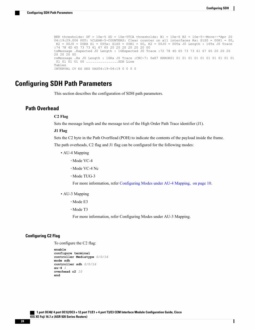
BER thresholds: SF = 10e-5 SD = 10e-5TCA thresholds: B1 = 10e-6 B2 = 10e-5--More--*Apr 2004:19:29.006 PDT: %CLEAR-5-COUNTERS: Clear counter on all interfaces Rx: S1S0 = 00K1 = 00,K2 = 00J0 = 00RX S1 = 00Tx: S1S0 = 00K1 = 00, K2 = 00J0 = 00Tx J0 Length : 16Tx J0 Trace:74 78 4D 65 73 73 61 67 65 20 20 20 20 20 20 00txMessage .Expected J0 Length : 16Expected J0 Trace :72 78 4D 65 73 73 61 67 65 20 20 2020 20 20 00rxMessage .Rx J0 Length : 16Rx J0 Trace :CRC-7: 0xE7 ERROR01 01 01 01 01 01 01 01 01 01 0101 01 01 01 00 ................SDH LineTablesINTERVAL CV ES SES UAS04:19-04:19 0 0 0 0
Configuring SDH Path ParametersThis section describes the configuration of SDH path parameters.
Path OverheadC2 Flag
Sets the message length and the message text of the High Order Path Trace identifier (J1).
J1 Flag
Sets the C2 byte in the Path OverHead (POH) to indicate the contents of the payload inside the frame.
The path overheads, C2 flag and J1 flag can be configured for the following modes:
• AU-4 Mapping
◦Mode VC-4
◦Mode VC-4 Nc
◦Mode TUG-3
For more information, refer Configuring Modes under AU-4 Mapping, on page 10.
• AU-3 Mapping
◦Mode E3
◦Mode T3
For more information, refer Configuring Modes under AU-3 Mapping.
Configuring C2 Flag
To configure the C2 flag:enableconfigure terminalcontroller Mediatype 0/0/16mode sdhcontroller sdh 0/0/16au-4 1overhead c2 10end
1 port OC48/ 4 port OC12/OC3 + 12 port T1/E1 + 4 port T3/E3 CEM Interface Module Configuration Guide, CiscoIOS XE Fuji 16.7.x (ASR 920 Series Routers)
24
Configuring SDHConfiguring SDH Path Parameters
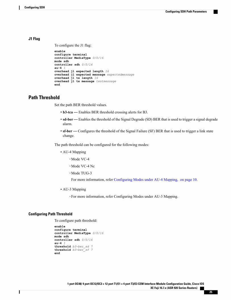
J1 Flag
To configure the J1 flag:enableconfigure terminalcontroller MediaType 0/0/16mode sdhcontroller sdh 0/0/16au-4 1overhead j1 expected length 16overhead j1 expected message expectedmessageoverhead j1 tx length 16overhead j1 tx message testmessageend
Path ThresholdSet the path BER threshold values.
• b3-tca— Enables BER threshold crossing alerts for B3.
• sd-ber— Enables the threshold of the Signal Degrade (SD) BER that is used to trigger a signal degradealarm.
• sf-ber— Configures the threshold of the Signal Failure (SF) BER that is used to trigger a link statechange.
The path threshold can be configured for the following modes:
• AU-4 Mapping
◦Mode VC-4
◦Mode VC-4 Nc
◦Mode TUG-3
For more information, refer Configuring Modes under AU-4 Mapping, on page 10.
• AU-3 Mapping
◦For more information, refer Configuring Modes under AU-3 Mapping.
Configuring Path Threshold
To configure path threshold:enableconfigure terminalcontroller MediaType 0/0/16mode sdhcontroller sdh 0/0/16au-4 1threshold b3-ber_sd 7threshold b3-ber_sf 7end
1 port OC48/ 4 port OC12/OC3 + 12 port T1/E1 + 4 port T3/E3 CEM Interface Module Configuration Guide, Cisco IOSXE Fuji 16.7.x (ASR 920 Series Routers)
25
Configuring SDHConfiguring SDH Path Parameters
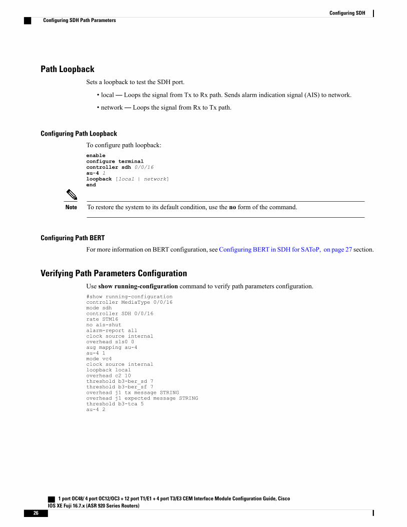
Path LoopbackSets a loopback to test the SDH port.
• local— Loops the signal from Tx to Rx path. Sends alarm indication signal (AIS) to network.
• network— Loops the signal from Rx to Tx path.
Configuring Path Loopback
To configure path loopback:enableconfigure terminalcontroller sdh 0/0/16au-4 1loopback [local | network]end
To restore the system to its default condition, use the no form of the command.Note
Configuring Path BERT
For more information on BERT configuration, see Configuring BERT in SDH for SAToP, on page 27 section.
Verifying Path Parameters ConfigurationUse show running-configuration command to verify path parameters configuration.#show running-configurationcontroller MediaType 0/0/16mode sdhcontroller SDH 0/0/16rate STM16no ais-shutalarm-report allclock source internaloverhead s1s0 0aug mapping au-4au-4 1mode vc4clock source internalloopback localoverhead c2 10threshold b3-ber_sd 7threshold b3-ber_sf 7overhead j1 tx message STRINGoverhead j1 expected message STRINGthreshold b3-tca 5au-4 2
1 port OC48/ 4 port OC12/OC3 + 12 port T1/E1 + 4 port T3/E3 CEM Interface Module Configuration Guide, CiscoIOS XE Fuji 16.7.x (ASR 920 Series Routers)
26
Configuring SDHConfiguring SDH Path Parameters
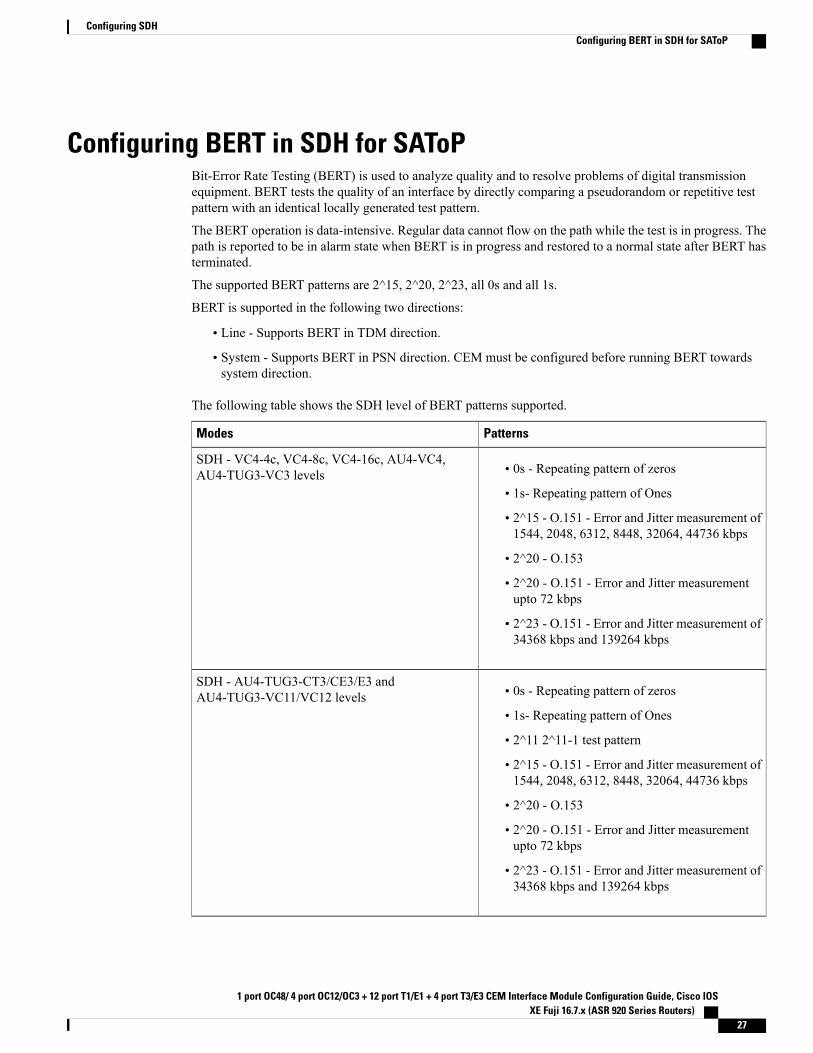
Configuring BERT in SDH for SAToPBit-Error Rate Testing (BERT) is used to analyze quality and to resolve problems of digital transmissionequipment. BERT tests the quality of an interface by directly comparing a pseudorandom or repetitive testpattern with an identical locally generated test pattern.
The BERT operation is data-intensive. Regular data cannot flow on the path while the test is in progress. Thepath is reported to be in alarm state when BERT is in progress and restored to a normal state after BERT hasterminated.
The supported BERT patterns are 2^15, 2^20, 2^23, all 0s and all 1s.
BERT is supported in the following two directions:
• Line - Supports BERT in TDM direction.
• System - Supports BERT in PSN direction. CEM must be configured before running BERT towardssystem direction.
The following table shows the SDH level of BERT patterns supported.
PatternsModes
• 0s - Repeating pattern of zeros
• 1s- Repeating pattern of Ones
• 2^15 - O.151 - Error and Jitter measurement of1544, 2048, 6312, 8448, 32064, 44736 kbps
• 2^20 - O.153
• 2^20 - O.151 - Error and Jitter measurementupto 72 kbps
• 2^23 - O.151 - Error and Jitter measurement of34368 kbps and 139264 kbps
SDH - VC4-4c, VC4-8c, VC4-16c, AU4-VC4,AU4-TUG3-VC3 levels
• 0s - Repeating pattern of zeros
• 1s- Repeating pattern of Ones
• 2^11 2^11-1 test pattern
• 2^15 - O.151 - Error and Jitter measurement of1544, 2048, 6312, 8448, 32064, 44736 kbps
• 2^20 - O.153
• 2^20 - O.151 - Error and Jitter measurementupto 72 kbps
• 2^23 - O.151 - Error and Jitter measurement of34368 kbps and 139264 kbps
SDH - AU4-TUG3-CT3/CE3/E3 andAU4-TUG3-VC11/VC12 levels
1 port OC48/ 4 port OC12/OC3 + 12 port T1/E1 + 4 port T3/E3 CEM Interface Module Configuration Guide, Cisco IOSXE Fuji 16.7.x (ASR 920 Series Routers)
27
Configuring SDHConfiguring BERT in SDH for SAToP
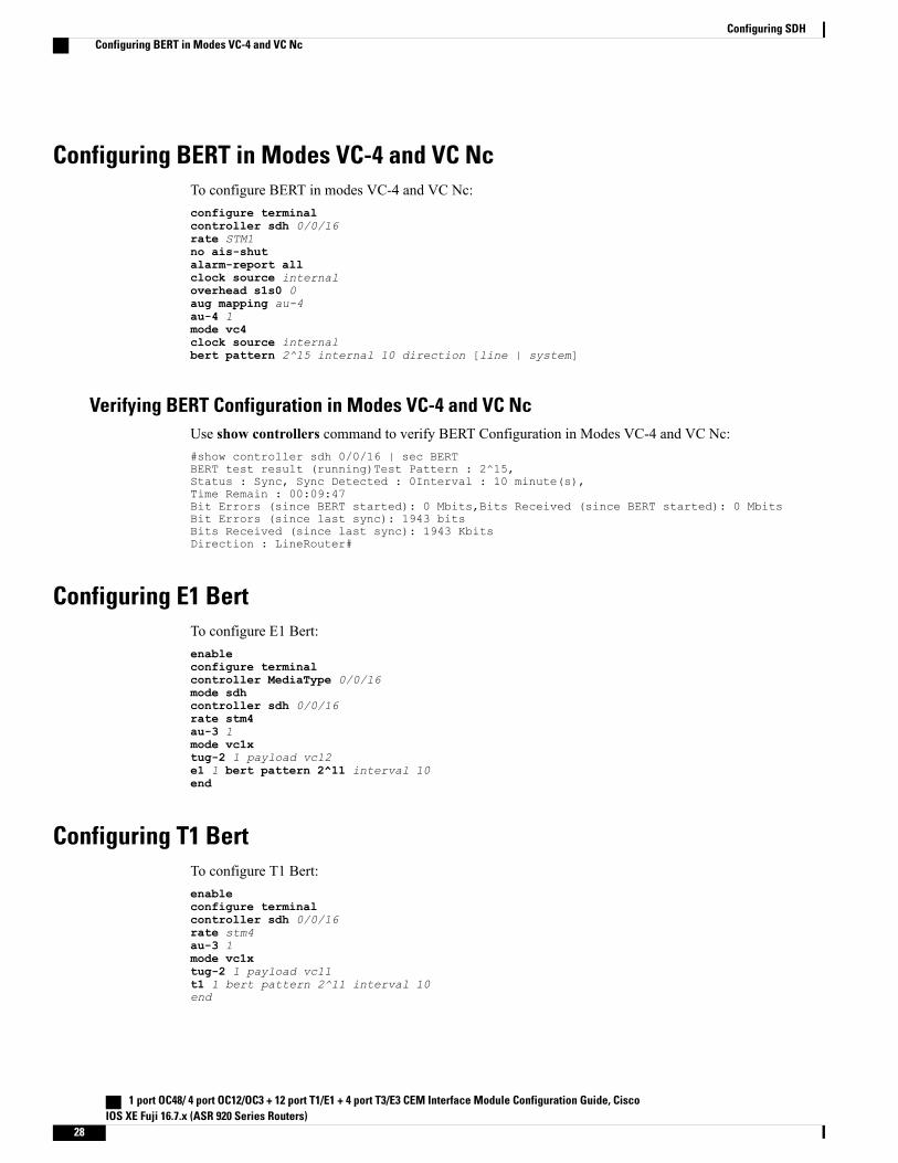
Configuring BERT in Modes VC-4 and VC NcTo configure BERT in modes VC-4 and VC Nc:configure terminalcontroller sdh 0/0/16rate STM1no ais-shutalarm-report allclock source internaloverhead s1s0 0aug mapping au-4au-4 1mode vc4clock source internalbert pattern 2^15 internal 10 direction [line | system]
Verifying BERT Configuration in Modes VC-4 and VC NcUse show controllers command to verify BERT Configuration in Modes VC-4 and VC Nc:#show controller sdh 0/0/16 | sec BERTBERT test result (running)Test Pattern : 2^15,Status : Sync, Sync Detected : 0Interval : 10 minute(s),Time Remain : 00:09:47Bit Errors (since BERT started): 0 Mbits,Bits Received (since BERT started): 0 MbitsBit Errors (since last sync): 1943 bitsBits Received (since last sync): 1943 KbitsDirection : LineRouter#
Configuring E1 BertTo configure E1 Bert:enableconfigure terminalcontroller MediaType 0/0/16mode sdhcontroller sdh 0/0/16rate stm4au-3 1mode vc1xtug-2 1 payload vc12e1 1 bert pattern 2^11 interval 10end
Configuring T1 BertTo configure T1 Bert:enableconfigure terminalcontroller sdh 0/0/16rate stm4au-3 1mode vc1xtug-2 1 payload vc11t1 1 bert pattern 2^11 interval 10end
1 port OC48/ 4 port OC12/OC3 + 12 port T1/E1 + 4 port T3/E3 CEM Interface Module Configuration Guide, CiscoIOS XE Fuji 16.7.x (ASR 920 Series Routers)
28
Configuring SDHConfiguring BERT in Modes VC-4 and VC Nc
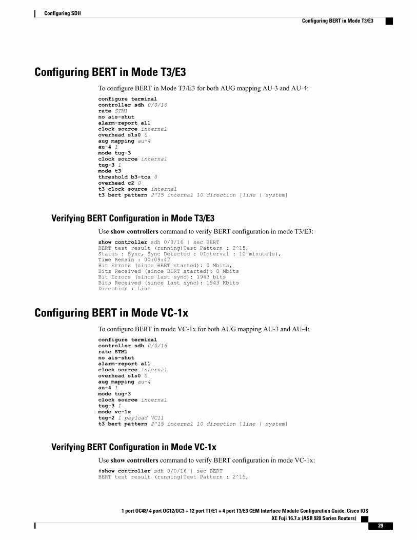
Configuring BERT in Mode T3/E3To configure BERT in Mode T3/E3 for both AUG mapping AU-3 and AU-4:configure terminalcontroller sdh 0/0/16rate STM1no ais-shutalarm-report allclock source internaloverhead s1s0 0aug mapping au-4au-4 1mode tug-3clock source internaltug-3 1mode t3threshold b3-tca 0overhead c2 0t3 clock source internalt3 bert pattern 2^15 internal 10 direction [line | system]
Verifying BERT Configuration in Mode T3/E3Use show controllers command to verify BERT configuration in mode T3/E3:show controller sdh 0/0/16 | sec BERTBERT test result (running)Test Pattern : 2^15,Status : Sync, Sync Detected : 0Interval : 10 minute(s),Time Remain : 00:09:47Bit Errors (since BERT started): 0 Mbits,Bits Received (since BERT started): 0 MbitsBit Errors (since last sync): 1943 bitsBits Received (since last sync): 1943 KbitsDirection : Line
Configuring BERT in Mode VC-1xTo configure BERT in mode VC-1x for both AUG mapping AU-3 and AU-4:configure terminalcontroller sdh 0/0/16rate STM1no ais-shutalarm-report allclock source internaloverhead s1s0 0aug mapping au-4au-4 1mode tug-3clock source internaltug-3 1mode vc-1xtug-2 1 payload VC11t3 bert pattern 2^15 internal 10 direction [line | system]
Verifying BERT Configuration in Mode VC-1xUse show controllers command to verify BERT configuration in mode VC-1x:#show controller sdh 0/0/16 | sec BERTBERT test result (running)Test Pattern : 2^15,
1 port OC48/ 4 port OC12/OC3 + 12 port T1/E1 + 4 port T3/E3 CEM Interface Module Configuration Guide, Cisco IOSXE Fuji 16.7.x (ASR 920 Series Routers)
29
Configuring SDHConfiguring BERT in Mode T3/E3
Status : Sync, Sync Detected : 0Interval : 10 minute(s),Time Remain : 00:09:47Bit Errors (since BERT started): 0 Mbits,Bits Received (since BERTstarted): 0 MbitsBit Errors (since last sync): 1943 bitsBits Received (since last sync): 1943 KbitsDirection : Line
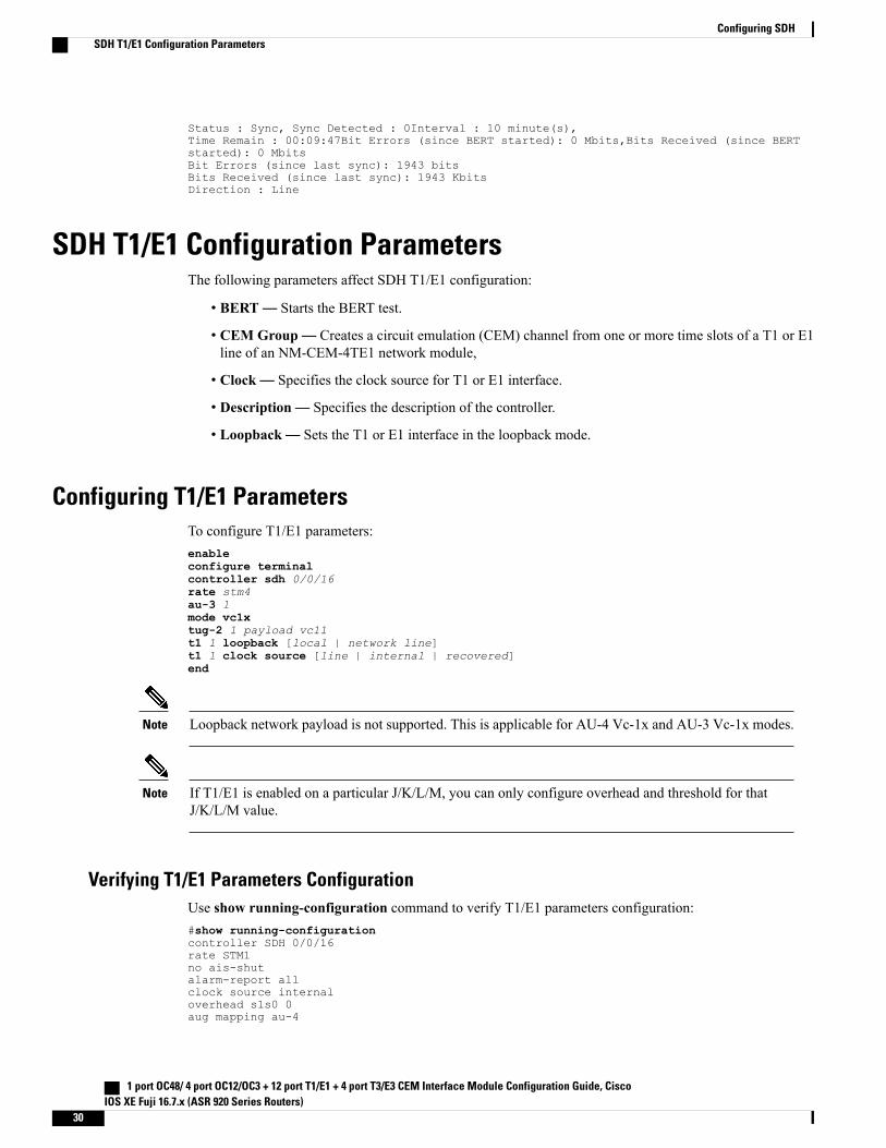
SDH T1/E1 Configuration ParametersThe following parameters affect SDH T1/E1 configuration:
• BERT— Starts the BERT test.
• CEM Group— Creates a circuit emulation (CEM) channel from one or more time slots of a T1 or E1line of an NM-CEM-4TE1 network module,
• Clock— Specifies the clock source for T1 or E1 interface.
• Description— Specifies the description of the controller.
• Loopback— Sets the T1 or E1 interface in the loopback mode.
Configuring T1/E1 ParametersTo configure T1/E1 parameters:enableconfigure terminalcontroller sdh 0/0/16rate stm4au-3 1mode vc1xtug-2 1 payload vc11t1 1 loopback [local | network line]t1 1 clock source [line | internal | recovered]end
Loopback network payload is not supported. This is applicable for AU-4 Vc-1x and AU-3 Vc-1x modes.Note
If T1/E1 is enabled on a particular J/K/L/M, you can only configure overhead and threshold for thatJ/K/L/M value.
Note
Verifying T1/E1 Parameters ConfigurationUse show running-configuration command to verify T1/E1 parameters configuration:#show running-configurationcontroller SDH 0/0/16rate STM1no ais-shutalarm-report allclock source internaloverhead s1s0 0aug mapping au-4
1 port OC48/ 4 port OC12/OC3 + 12 port T1/E1 + 4 port T3/E3 CEM Interface Module Configuration Guide, CiscoIOS XE Fuji 16.7.x (ASR 920 Series Routers)
30
Configuring SDHSDH T1/E1 Configuration Parameters
au-4 1clock source internalmode tug-3tug-3 2mode VC1xtug-2 1 payload VC11t1 1 loopback network linet1 1 clock source line
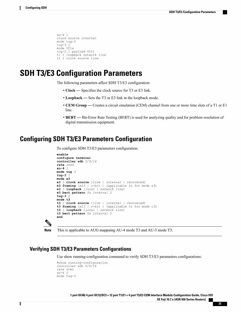
SDH T3/E3 Configuration ParametersThe following parameters affect SDH T3/E3 configuration:
• Clock— Specifies the clock source for T3 or E3 link.
• Loopback— Sets the T3 or E3 link in the loopback mode.
• CEM Group— Creates a circuit emulation (CEM) channel from one or more time slots of a T1 or E1line.
• BERT— Bit-Error Rate Testing (BERT) is used for analyzing quality and for problem resolution ofdigital transmission equipment.
Configuring SDH T3/E3 Parameters ConfigurationTo configure SDH T3/E3 parameters configuration:enableconfigure terminalcontroller sdh 0/0/16rate stm4au-4 1mode tug 3tug-3 1mode e3e3 1 clock source [line | internal | recovered]e3 framing [m13 | c-bit ] (applicable to for mode e3)e3 1 loopback [local | network line]e3 bert pattern 0s interval 2tug-3 2mode t3t3 1 clock source [line | internal | recovered]t3 framing [m13 | c-bit ] (applicable to for mode t3)t3 1 loopback [local | network line]t3 bert pattern 0s interval 2end
This is applicable to AUG mappaing AU-4 mode T3 and AU-3 mode T3.Note
Verifying SDH T3/E3 Parameters ConfigurationsUse show running-configuration command to verify SDH T3/E3 parameters configurations:#show running-configurationcontroller sdh 0/0/16rate stm1au-4 2mode tug-3
1 port OC48/ 4 port OC12/OC3 + 12 port T1/E1 + 4 port T3/E3 CEM Interface Module Configuration Guide, Cisco IOSXE Fuji 16.7.x (ASR 920 Series Routers)
31
Configuring SDHSDH T3/E3 Configuration Parameters
clock source internaltug-3 1mode E3threshold b3-tca 0overhead c2 0e3 clock source internale3 framing g751!tug-3 2mode T3threshold b3-tca 0overhead c2 0t3 clock source internalt3 framing c-bit!
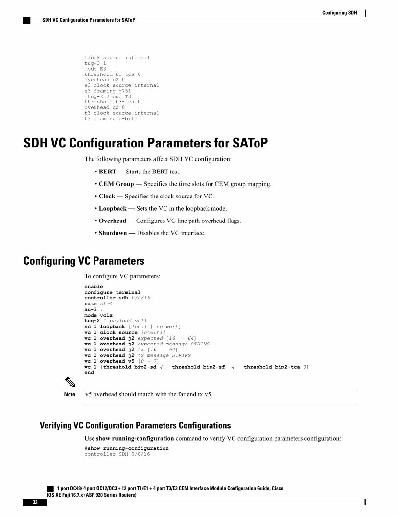
SDH VC Configuration Parameters for SAToPThe following parameters affect SDH VC configuration:
• BERT— Starts the BERT test.
• CEM Group— Specifies the time slots for CEM group mapping.
• Clock— Specifies the clock source for VC.
• Loopback— Sets the VC in the loopback mode.
• Overhead— Configures VC line path overhead flags.
• Shutdown— Disables the VC interface.
Configuring VC ParametersTo configure VC parameters:enableconfigure terminalcontroller sdh 0/0/16rate stm4au-3 1mode vc1xtug-2 1 payload vc11vc 1 loopback [local | network]vc 1 clock source internalvc 1 overhead j2 expected [16 | 64]vc 1 overhead j2 expected message STRINGvc 1 overhead j2 tx [16 | 64]vc 1 overhead j2 tx message STRINGvc 1 overhead v5 [0 - 7]vc 1 [threshold bip2-sd 4 | threshold bip2-sf 4 | threshold bip2-tca 9]end
v5 overhead should match with the far end tx v5.Note
Verifying VC Configuration Parameters ConfigurationsUse show running-configuration command to verify VC configuration parameters configuration:#show running-configurationcontroller SDH 0/0/16
1 port OC48/ 4 port OC12/OC3 + 12 port T1/E1 + 4 port T3/E3 CEM Interface Module Configuration Guide, CiscoIOS XE Fuji 16.7.x (ASR 920 Series Routers)
32
Configuring SDHSDH VC Configuration Parameters for SAToP
rate STM1no ais-shutalarm-report allclock source internaloverhead s1s0 0aug mapping au-4au-4 1clock source internalmode tug-3tug-3 1mode VC1xtug-2 1 payload VC11vc 1 overhead j2 tx message STRINGvc 1 overhead j2 expected message STRINGvc 1 threshold bip2-sd 4vc 1 threshold bip2-sf 4vc 1 threshold bip2-tca 9
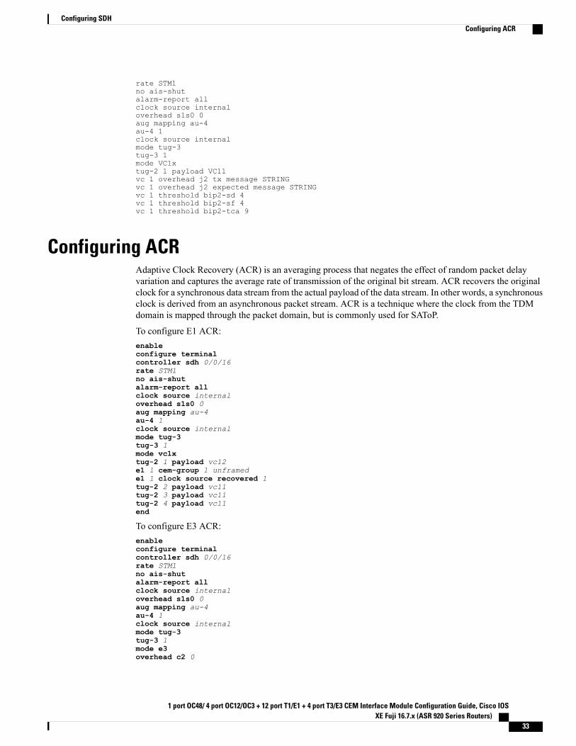
Configuring ACRAdaptive Clock Recovery (ACR) is an averaging process that negates the effect of random packet delayvariation and captures the average rate of transmission of the original bit stream. ACR recovers the originalclock for a synchronous data stream from the actual payload of the data stream. In other words, a synchronousclock is derived from an asynchronous packet stream. ACR is a technique where the clock from the TDMdomain is mapped through the packet domain, but is commonly used for SAToP.
To configure E1 ACR:enableconfigure terminalcontroller sdh 0/0/16rate STM1no ais-shutalarm-report allclock source internaloverhead s1s0 0aug mapping au-4au-4 1clock source internalmode tug-3tug-3 1mode vc1xtug-2 1 payload vc12e1 1 cem-group 1 unframede1 1 clock source recovered 1tug-2 2 payload vc11tug-2 3 payload vc11tug-2 4 payload vc11end
To configure E3 ACR:enableconfigure terminalcontroller sdh 0/0/16rate STM1no ais-shutalarm-report allclock source internaloverhead s1s0 0aug mapping au-4au-4 1clock source internalmode tug-3tug-3 1mode e3overhead c2 0
1 port OC48/ 4 port OC12/OC3 + 12 port T1/E1 + 4 port T3/E3 CEM Interface Module Configuration Guide, Cisco IOSXE Fuji 16.7.x (ASR 920 Series Routers)
33
Configuring SDHConfiguring ACR
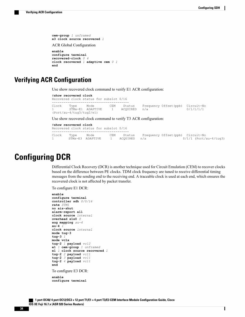
cem-group 1 unframede3 clock source recovered 1
ACR Global Configurationenableconfigure terminalrecovered-clock 0 4clock recovered 1 adaptive cem 0 1end
Verifying ACR ConfigurationUse show recovered clock command to verify E1 ACR configuration:#show recovered clockRecovered clock status for subslot 0/16----------------------------------------Clock Type Mode CEM Status Frequency Offset(ppb) Circuit-No1 STMx-E1 ADAPTIVE 1 ACQUIRED n/a 0/1/1/1/1(Port/au-4/tug3/tug2/e1)
Use show recovered clock command to verify T3 ACR configuration:#show recovered clockRecovered clock status for subslot 0/16----------------------------------------Clock Type Mode CEM Status Frequency Offset(ppb) Circuit-No1 STMx-E3 ADAPTIVE 1 ACQUIRED n/a 0/1/1 (Port/au-4/tug3)
Configuring DCRDifferential Clock Recovery (DCR) is another technique used for Circuit Emulation (CEM) to recover clocksbased on the difference between PE clocks. TDM clock frequency are tuned to receive differential timingmessages from the sending end to the receiving end. A traceable clock is used at each end, which ensures therecovered clock is not affected by packet transfer.
To configure E1 DCR:enableconfigure terminalcontroller sdh 0/0/16rate STM1no ais-shutalarm-report allclock source internaloverhead s1s0 0aug mapping au-4au-4 1clock source internalmode tug-3tug-3 1mode vc1xtug-2 1 payload vc12e1 1 cem-group 1 unframede1 1 clock source recovered 1tug-2 2 payload vc11tug-2 3 payload vc11tug-2 4 payload vc11end
To configure E3 DCR:enableconfigure terminal
1 port OC48/ 4 port OC12/OC3 + 12 port T1/E1 + 4 port T3/E3 CEM Interface Module Configuration Guide, CiscoIOS XE Fuji 16.7.x (ASR 920 Series Routers)
34
Configuring SDHVerifying ACR Configuration
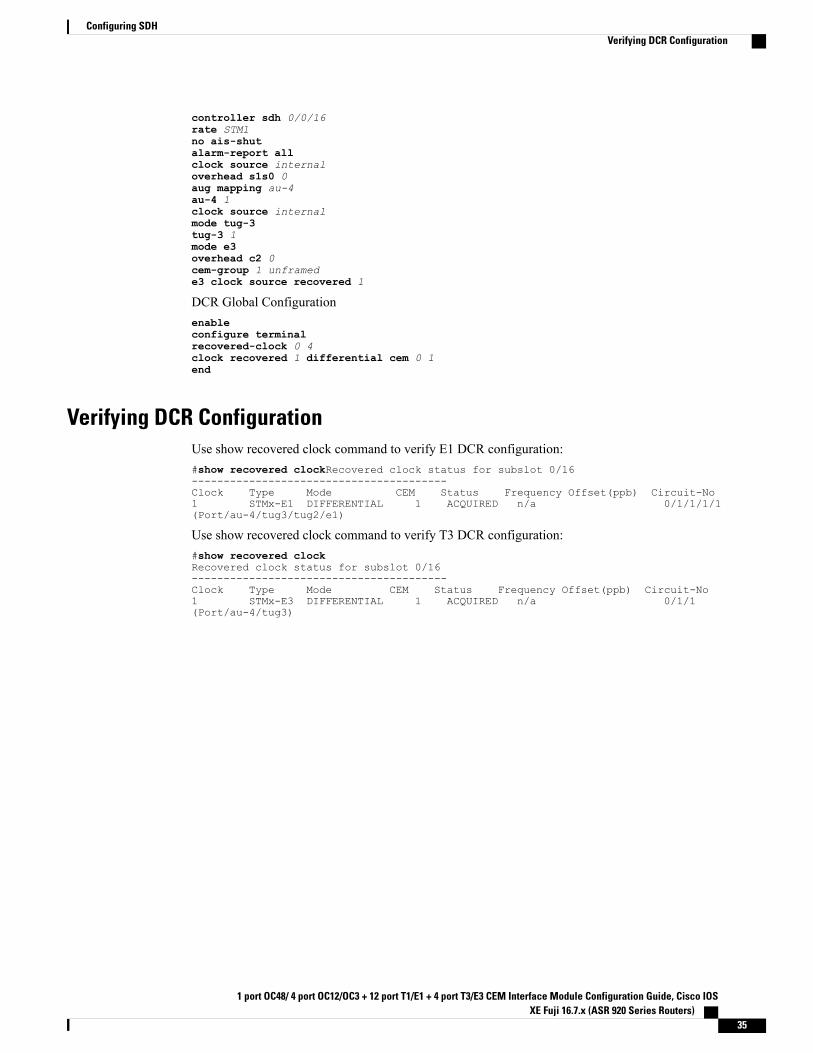
controller sdh 0/0/16rate STM1no ais-shutalarm-report allclock source internaloverhead s1s0 0aug mapping au-4au-4 1clock source internalmode tug-3tug-3 1mode e3overhead c2 0cem-group 1 unframede3 clock source recovered 1
DCR Global Configurationenableconfigure terminalrecovered-clock 0 4clock recovered 1 differential cem 0 1end
Verifying DCR ConfigurationUse show recovered clock command to verify E1 DCR configuration:#show recovered clockRecovered clock status for subslot 0/16----------------------------------------Clock Type Mode CEM Status Frequency Offset(ppb) Circuit-No1 STMx-E1 DIFFERENTIAL 1 ACQUIRED n/a 0/1/1/1/1(Port/au-4/tug3/tug2/e1)
Use show recovered clock command to verify T3 DCR configuration:#show recovered clockRecovered clock status for subslot 0/16----------------------------------------Clock Type Mode CEM Status Frequency Offset(ppb) Circuit-No1 STMx-E3 DIFFERENTIAL 1 ACQUIRED n/a 0/1/1(Port/au-4/tug3)
1 port OC48/ 4 port OC12/OC3 + 12 port T1/E1 + 4 port T3/E3 CEM Interface Module Configuration Guide, Cisco IOSXE Fuji 16.7.x (ASR 920 Series Routers)
35
Configuring SDHVerifying DCR Configuration
1 port OC48/ 4 port OC12/OC3 + 12 port T1/E1 + 4 port T3/E3 CEM Interface Module Configuration Guide, CiscoIOS XE Fuji 16.7.x (ASR 920 Series Routers)
36
Configuring SDHVerifying DCR Configuration