confocal imaging of myeloid cells in the corneal … · confocal imaging of myeloid cells in the...
TRANSCRIPT
http://www.bio-protocol.org/e1517 Vol 5, Iss 13, Jul 05, 2015
Copyright © 2015 The Authors; exclusive licensee Bio-protocol LLC. 1
Confocal Imaging of Myeloid Cells in the Corneal Stroma of Live Mice
Matilda F. Chan1, 2* and Zena Werb3
1Francis I. Proctor Foundation, University of California, San Francisco, California; 2Department
of Ophthalmology, University of California, San Francisco, California; 3Department of Anatomy,
University of California, San Francisco, USA
*For correspondence: [email protected]
[Abstract] The accessibility and transparency of the cornea makes it a good tissue model for
monitoring immunological responses using in vivo real time imaging analysis (Lee et al., 2010;
Tan et al., 2013). These corneal qualities have also allowed for high-resolution in vivo imaging
of non-ocular tissue transplanted into the anterior chamber of the mouse eye (Speier et al.,
2008a; Speier et al., 2008b). This protocol was adapted from Speier (2008) to successfully
assess real-time in vivo myeloid cell dynamics in wounded corneas of c-fms-EGFP mice
(Chan et al., 2013). Macrophage colony-stimulating factor (CSF-1) regulates the differentiation
and proliferation of cells of the mononuclear phagocyte system. The activity of CSF-1 is
mediated by the CSF-1 receptor that is encoded by c-fms (Csf1r) protooncogene. The c-fms
gene is expressed in macrophage, trophoblast cell lineages, and to some extent granulocytes.
In the c-fms-EGFP mice EGFP, enhanced green fluorescent protein, is driven under the Csf1r,
colony stimulating factor 1 receptor, promoter and highlights myeloid cells (Sasmono et al.,
2003). This protocol can be further adapted to image other transgenic mice expressing
fluorescent proteins.
Materials and Reagents
1. c-fms-EGFP mouse whose cornea was wounded by chemical injury 1 day prior (Chan
and Werb, 2015)
2. Avertin (Sigma-Aldrich, catalog number: T4, 840-2)
3. 15.5 ml tert-amyl alcohol (2-methyl-2-butanol) (Thermo Fisher Scientific, catalog
number: A730-1)
4. Saline 0.9%
5. GenTeal gel (0.3%, eye gel) (Novartis, NDC: 0078-0429-47)
6. Avertin stock solution (see Recipes)
7. Avertin working solution (1.2%) (see Recipes)
Equipment
1. 25 Gauge needle
2. 5 ml and 50 ml syringes
http://www.bio-protocol.org/e1517 Vol 5, Iss 13, Jul 05, 2015
Copyright © 2015 The Authors; exclusive licensee Bio-protocol LLC. 2
3. 1.5 ml microcentrifuge tubes
4. 0.22 micron filter
5. Head-holding adapter (Narishige, catalog number: SG-4N)
6. Dumont no. 5 forceps (Fine Science Tools, catalog number: 11251-10)
7. UST-2 Solid Universal Joint (Narishige, catalog number: UST-2)
8. Polyethylene tubing (0.28 mm i.d., 0.61 mm o.d.) (Warner Instruments, catalog
number: 64- 0750)
9. Heating pad
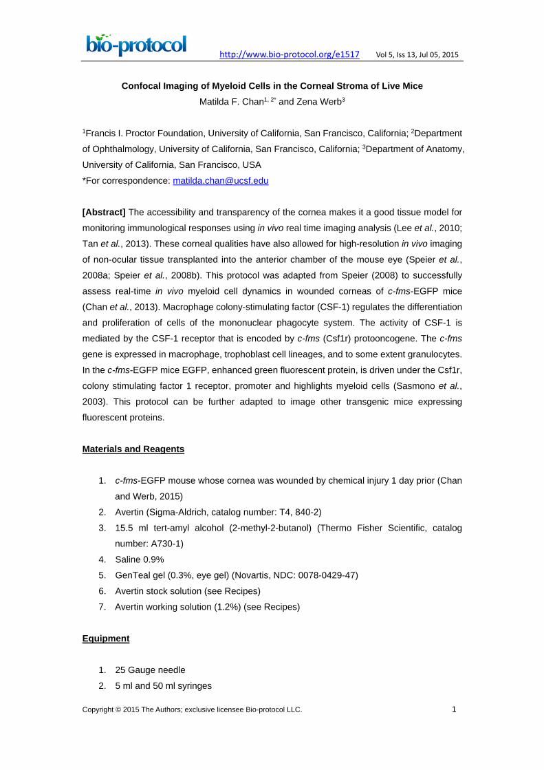
10. Nikon Spectral Confocal (C1Si) equipped with a GFP filter, an argon laser, a 40x
objective (NIR/ 0.8 NA W lens) and camera (Nikon D-eclipse C1Si) (Figure 1)
Figure 1. Confocal setup. The imaging setup includes a confocal microscope,
camera, argon laser, and computer.
Software
1. Nikon Confocal Software (Nikon, Ez-C1 Gold version 3.8)
2. Imaris Software (Bitplane, version 7.3.1 for Windows X64)
Procedure Ethical statement: All procedures discussed here are in accordance with and were approved
by the University of California, San Francisco Institutional Animal Care and Use Committee.
1. Setup the Confocal Microscope.
a. Turn on the argon laser.
b. Open imaging software Ez-C1 Gold Ver. 3.8.
2. Setup the head-holding adapter (Figure 2).

http://www.bio-protocol.org/e1517 Vol 5, Iss 13, Jul 05, 2015
Copyright © 2015 The Authors; exclusive licensee Bio-protocol LLC. 3
Figure 2. Head-holding adapter setup. The mouse head is stabilized by fixing the
nose and ears in place using the nose piece and ear bars.
3. Setup the eye stabilizer (Figure 3).
a. Attach the no. 5 Dumont forceps to the UST-2 Solid Universal Joint.
b. Cut an 18 mm piece of polyethylene tubing. The polyethylene tubing serves to
isolate and stabilize the whole eye. Cover the tips of the forceps with the tubing,
creating a loop between the tips.
Figure 3. Eye stabilizer setup. The mouse eye is stabilized by looping and tightening
the tubing around the eye.
4. Place the heating pad under the objective. The heating pad is used to maintain body
temperature at 37 °C during the procedure.
5. Anesthetize the mouse by injecting 1.2% Avertin solution using a dosage of 0.2 ml/10
grams body weight intraperitoneally with a 25 Gauge needle. It is critical to minimize
breathing movements as much as possible so anesthetize the mouse until the
breathing is very shallow and not rapid.
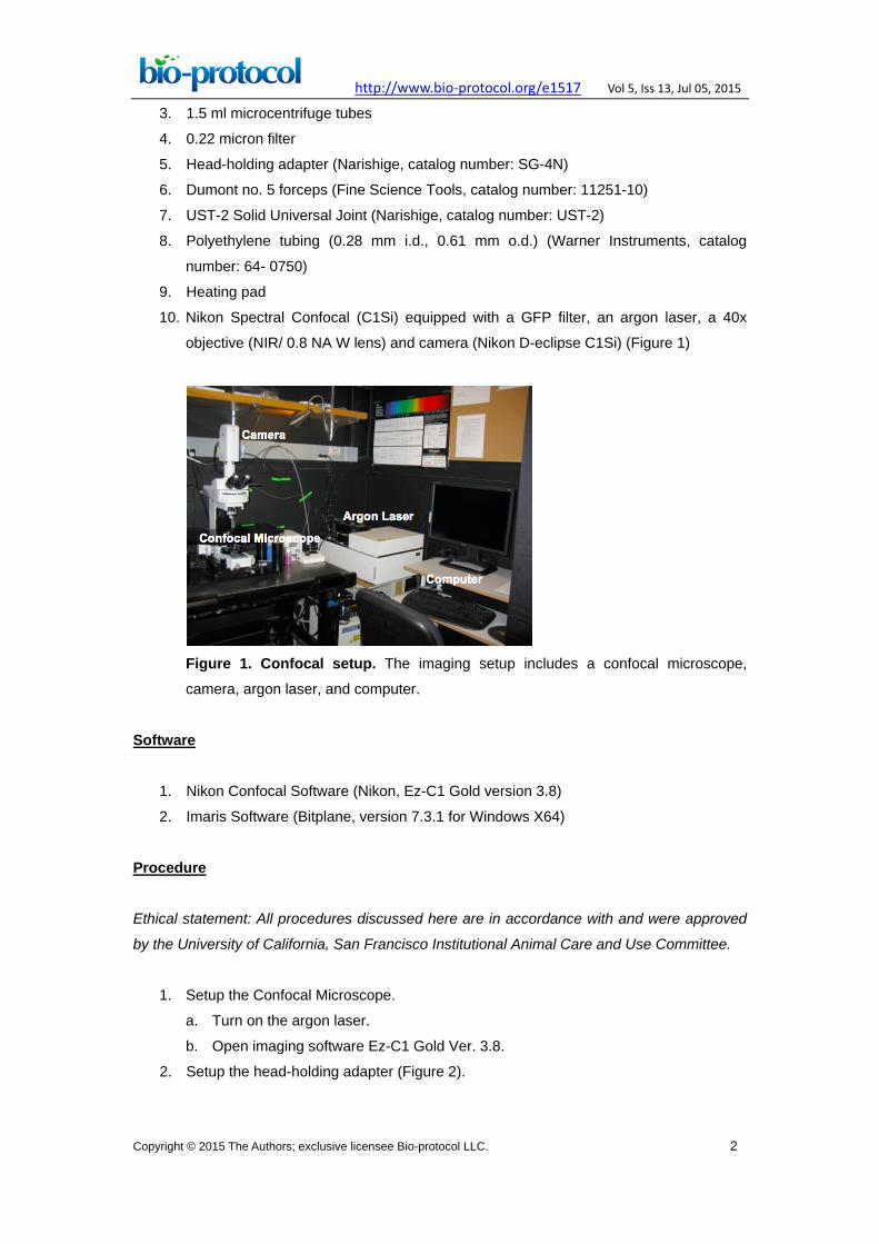
6. After the mouse is fully anesthetized, place the mouse’s head in the head-holding
adapter (Figure 4).
http://www.bio-protocol.org/e1517 Vol 5, Iss 13, Jul 05, 2015
Copyright © 2015 The Authors; exclusive licensee Bio-protocol LLC. 4
Figure 4. Placement of mouse in head-holding adapter. The mouse head is fixed in
place using the nose piece and ear bars.
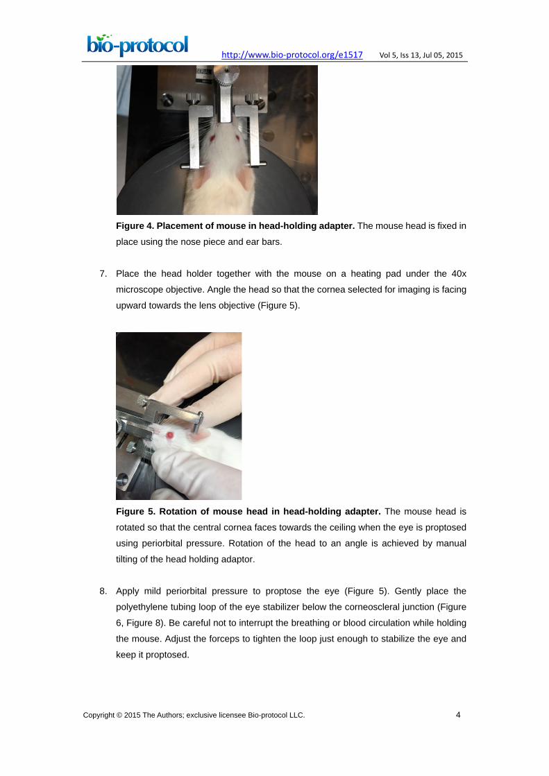
7. Place the head holder together with the mouse on a heating pad under the 40x
microscope objective. Angle the head so that the cornea selected for imaging is facing
upward towards the lens objective (Figure 5).
Figure 5. Rotation of mouse head in head-holding adapter. The mouse head is
rotated so that the central cornea faces towards the ceiling when the eye is proptosed
using periorbital pressure. Rotation of the head to an angle is achieved by manual
tilting of the head holding adaptor.
8. Apply mild periorbital pressure to proptose the eye (Figure 5). Gently place the
polyethylene tubing loop of the eye stabilizer below the corneoscleral junction (Figure
6, Figure 8). Be careful not to interrupt the breathing or blood circulation while holding
the mouse. Adjust the forceps to tighten the loop just enough to stabilize the eye and
keep it proptosed.
http://www.bio-protocol.org/e1517 Vol 5, Iss 13, Jul 05, 2015
Copyright © 2015 The Authors; exclusive licensee Bio-protocol LLC. 5
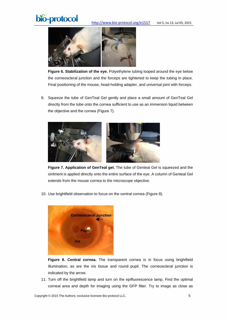
Figure 6. Stabilization of the eye. Polyethylene tubing looped around the eye below
the corneoscleral junction and the forceps are tightened to keep the tubing in place.
Final positioning of the mouse, head-holding adapter, and universal joint with forceps.
9. Squeeze the tube of GenTeal Gel gently and place a small amount of GenTeal Gel
directly from the tube onto the cornea sufficient to use as an immersion liquid between
the objective and the cornea (Figure 7).
Figure 7. Application of GenTeal gel. The tube of Genteal Gel is squeezed and the
ointment is applied directly onto the entire surface of the eye. A column of Genteal Gel
extends from the mouse cornea to the microscope objective.
10. Use brightfield observation to focus on the central cornea (Figure 8).
Figure 8. Central cornea. The transparent cornea is in focus using brightfield
illumination, as are the iris tissue and round pupil. The corneoscleral junction is
indicated by the arrow.
11. Turn off the brightfield lamp and turn on the epifluorescence lamp. Find the optimal
corneal area and depth for imaging using the GFP filter. Try to image as close as
http://www.bio-protocol.org/e1517 Vol 5, Iss 13, Jul 05, 2015
Copyright © 2015 The Authors; exclusive licensee Bio-protocol LLC. 6
possible to the central cornea because it is flatter than the paracentral cornea and
allows for more cells to be in focus within the same plane.
12. Switch the microscope setting from epifluorescence to confocal. Select a filter cube
with 488 excitation. Open imaging software Ez-C1 Gold Ver. 3.8. and use the following
acquisition settings. The below settings optimize the resolution of the myeloid cells
while limiting the amount of photobleaching.
a. Pinhole: large (may use a smaller pinhole if there is enough signal)
b. Beam Splitter: 408/488/581or 488/561/638
c. Excitation intensity: for 488 = up to 10%
d. Lines per dimension: 512 x 512
e. Gain: 180-190 (may adjust as needed)
f. Pixel dwell: between 6 and 8
g. Timelapse-as fast as possible
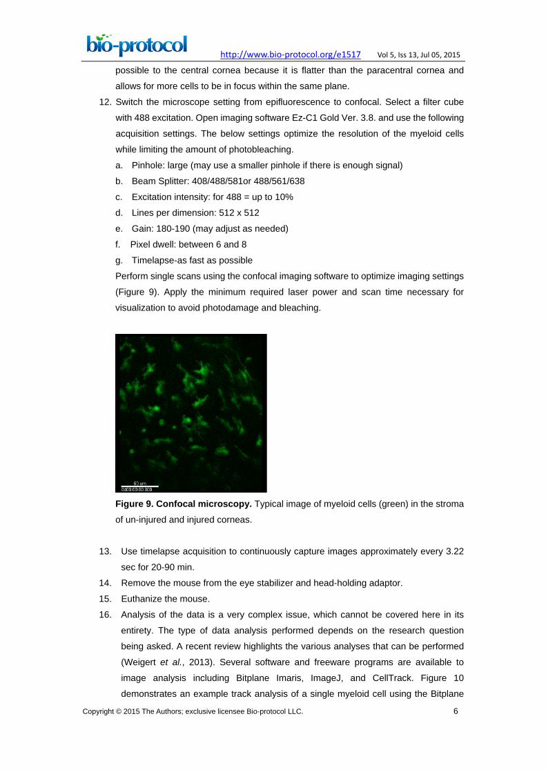
Perform single scans using the confocal imaging software to optimize imaging settings
(Figure 9). Apply the minimum required laser power and scan time necessary for
visualization to avoid photodamage and bleaching.
Figure 9. Confocal microscopy. Typical image of myeloid cells (green) in the stroma
of un-injured and injured corneas.
13. Use timelapse acquisition to continuously capture images approximately every 3.22
sec for 20-90 min.
14. Remove the mouse from the eye stabilizer and head-holding adaptor.
15. Euthanize the mouse.
16. Analysis of the data is a very complex issue, which cannot be covered here in its
entirety. The type of data analysis performed depends on the research question
being asked. A recent review highlights the various analyses that can be performed
(Weigert et al., 2013). Several software and freeware programs are available to
image analysis including Bitplane Imaris, ImageJ, and CellTrack. Figure 10
demonstrates an example track analysis of a single myeloid cell using the Bitplane

http://www.bio-protocol.org/e1517 Vol 5, Iss 13, Jul 05, 2015
Copyright © 2015 The Authors; exclusive licensee Bio-protocol LLC. 7
Imaris software program. Detailed Imaris software instructions are available through
the company website (http://www.bitplane.com/imaris). Axial fluctuations manifested
by slow changes to specimen focus may occur over the course of time-lapse imaging.
The Imaris software program can help correct for these fluctuations in focus through
its drift correction function.
Figure 10. Image analysis. Sample motility analysis of a single myeloid cell over 90
minutes using the Bitplane Imaris software program. Recipes
1. Avertin stock solution
Mix 25 g Avertin (2, 2, 2-Tribromoethanol) with 15.5 ml tert-amyl alcohol
(2-methyl-2-butanol) at room temperature for 12 h in a dark bottle
Make 0.5 ml stocks
Stored at -20 °C in the dark
2. Avertin working solution (1.2%)
Pre-warm 0.9% saline at 20 °C
Mix 0.5 ml Avertin stock with 39.5 ml pre-warmed 0.9% saline
Mix in an airtight dark or foil covered container
Filter the solution though a 0.22 micron filter into a dark or foil covered container
Stored at 4 °C
The working solution expires in 1 week
Acknowledgements

http://www.bio-protocol.org/e1517 Vol 5, Iss 13, Jul 05, 2015
Copyright © 2015 The Authors; exclusive licensee Bio-protocol LLC. 8
This protocol was adapted from Speier et al. (2008). This work was supported by grants
from the National Institutes of Health (K08 EY018858 and R01 EY002162 to M.F.C. and
R01 CA057621and P01 AI053194 to Z.W.).
References
1. Chan, M. F. and Werb, Z. (2015). Animal models of corneal injury. Bio-protocol 5(13):
e1516.
2. Chan, M. F., Li, J., Bertrand, A., Casbon, A. J., Lin, J. H., Maltseva, I. and Werb, Z.
(2013). Protective effects of matrix metalloproteinase-12 following corneal injury. J
Cell Sci 126(Pt 17): 3948-3960.
3. Lee, E. J., Rosenbaum, J. T. and Planck, S. R. (2010). Epifluorescence intravital
microscopy of murine corneal dendritic cells. Invest Ophthalmol Vis Sci 51(4):
2101-2108.
4. Sasmono, R. T., Oceandy, D., Pollard, J. W., Tong, W., Pavli, P., Wainwright, B. J.,
Ostrowski, M. C., Himes, S. R. and Hume, D. A. (2003). A macrophage
colony-stimulating factor receptor–green fluorescent protein transgene is expressed
throughout the mononuclear phagocyte system of the mouse. Blood 101(3):
1155-1163.
5. Speier, S., Nyqvist, D., Cabrera, O., Yu, J., Molano, R. D., Pileggi, A., Moede, T.,
Kohler, M., Wilbertz, J., Leibiger, B., Ricordi, C., Leibiger, I. B., Caicedo, A. and
Berggren, P. O. (2008a). Noninvasive in vivo imaging of pancreatic islet cell biology.
Nat Med 14(5): 574-578.
6. Speier, S., Nyqvist, D., Kohler, M., Caicedo, A., Leibiger, I. B. and Berggren, P. O.
(2008b). Noninvasive high-resolution in vivo imaging of cell biology in the anterior
chamber of the mouse eye. Nat Protoc 3(8): 1278-1286.
7. Tan, Y., Abdulreda, M. H., Cruz-Guilloty, F., Cutrufello, N., Shishido, A., Martinez, R.
E., Duffort, S., Xia, X., Echegaray-Mendez, J., Levy, R. B., Berggren, P. O. and Perez,
V. L. (2013). Role of T cell recruitment and chemokine-regulated intra-graft T cell
motility patterns in corneal allograft rejection. Am J Transplant 13(6): 1461-1473.
8. Weigert, R., Porat-Shliom, N. and Amornphimoltham, P. (2013). Imaging cell biology
in live animals: ready for prime time. J Cell Biol 201(7): 969-979.