confocal microscopy - principles and applications
TRANSCRIPT
Confocal Microscopy 1
Confocal Microscopy - principles and applications
Dave Johnston / Anton Page
Biomedical Imaging Unit

Confocal Microscopy 2
focus - standard microscopy
In standard microscopy, unless the specimenis very thin then areas of the specimen aboveand below the focal plane still contribute tothe image as "out of focus blur"

Confocal Microscopy 3
focus - confocal microscopy
In confocal microscopy, a pinhole betweenspecimen and detector is used to selectinformation from a single focal plane,producing a sharply focussed optical slicethrough the specimen.
Taking a series of optical slices fromdifferent focus levels in the specimengenerates a 3D data set.

Confocal Microscopy 4
laser scanning confocal microscopy
a pair of oscillating mirrors raster scan a pointof laser light across the specimen via theobjective (epi-illumination) .
Fluorescence emitted by the specimen passesback through the mirror systems to a beamsplitter which rejects any reflected excitationwavelengths and then through the pinhole togenerate the optical slice.
The detector (a photomultiplier tube) simplyrecords the brightness of fluorescence at eachraster point and maps this into a 2D(XY)image.

Confocal Microscopy 5
Leica wavelength selective elements
Laser
Excitation selectionmodule
Spectral detection unit
Beam splitter
Specimen
just as in conventional fluorescence microscopy,confocal microscopes need systems to: (1) selectthe excitation wavelength (2) discriminate betweenexcitation and emission (3) restrict thewavelengths detected
1
2
3
Confocal Microscopy 6
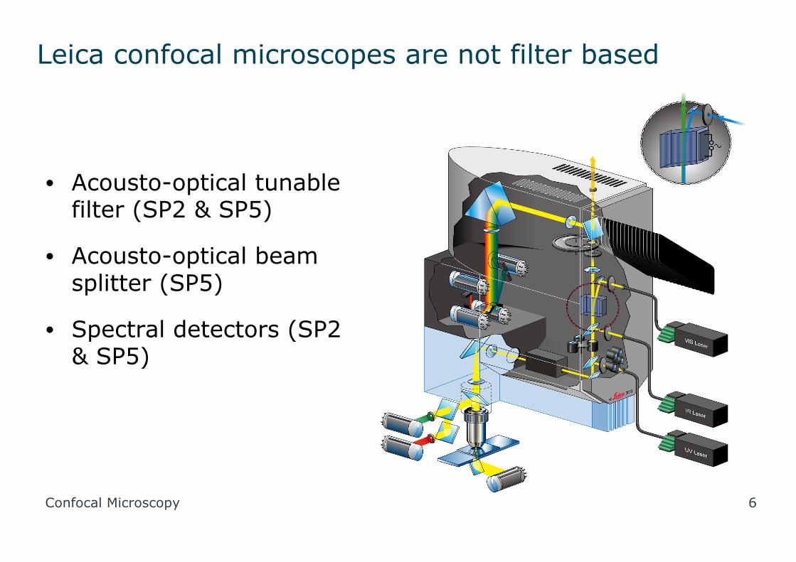
Leica confocal microscopes are not filter based
• Acousto-optical tunablefilter (SP2 & SP5)
• Acousto-optical beamsplitter (SP5)
• Spectral detectors (SP2& SP5)
Confocal Microscopy 7
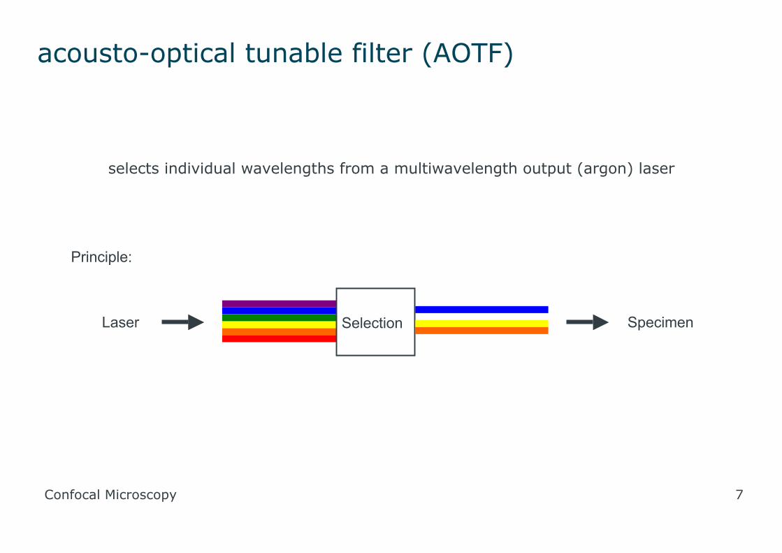
acousto-optical tunable filter (AOTF)
SelectionLaser Specimen
Principle:
selects individual wavelengths from a multiwavelength output (argon) laser

Confocal Microscopy 8
AOBS acts like a dichroic beam splittter toseparate shorter wavelength / higher energyreflected excitation from longer wavelength
fluorescent emission
acousto optical beam splitter (AOBS)

Confocal Microscopy 9
AOBS efficiency
AOBS shows a very clean, sharp cut off between signal transmission andrejection compared to standard optical beamsplitters

Confocal Microscopy 10
AOBS benefits
• Fast switching between channels
• Less bleed through with multiple labelling
• Higher signal transmission
• Less bleaching by optimising excitation intensity
• Easier region-of-interest scanning

Confocal Microscopy 11
spectral detection
• can detect any emission wavelength in the visible andnear infra-red
• no need to buy new filters when new dyes areintroduced

Confocal Microscopy 12
Leica spectral detector
fluorescence is focused into a parallel"rainbow" light path
a slit edged with mirrors can be moved acrossthe light path and opened or closed to specifywhich wavelengths reach the detector behindthe slit
other wavelengths are deflected by the mirrorstowards other detector /mirror / slit units
detectors simply measure brightness within thespecified spectral range on a 256 level greyscale
false colour look up tables are used to map theintensity of each channel into arbitrary colours
our Leica SP5 has 4 spectral detectors

Confocal Microscopy 13
simultaneous acquisition
RH tail of FITC fluorescence falls within spectral region being monitored for TRITCfluorescence, ditto (to a lesser extent) for RH tail of TRITC fluorescence in CY5
detection region

Confocal Microscopy 14
sequential acquisition
no TRITC region detection when FITC is being excited

Confocal Microscopy 15
sequential acquisition
no FITC fluorescence when TRITC is being excited

Confocal Microscopy 16
sequential acquisition
no TRITC fluorescence when CY5 is being excited
Confocal Microscopy 17
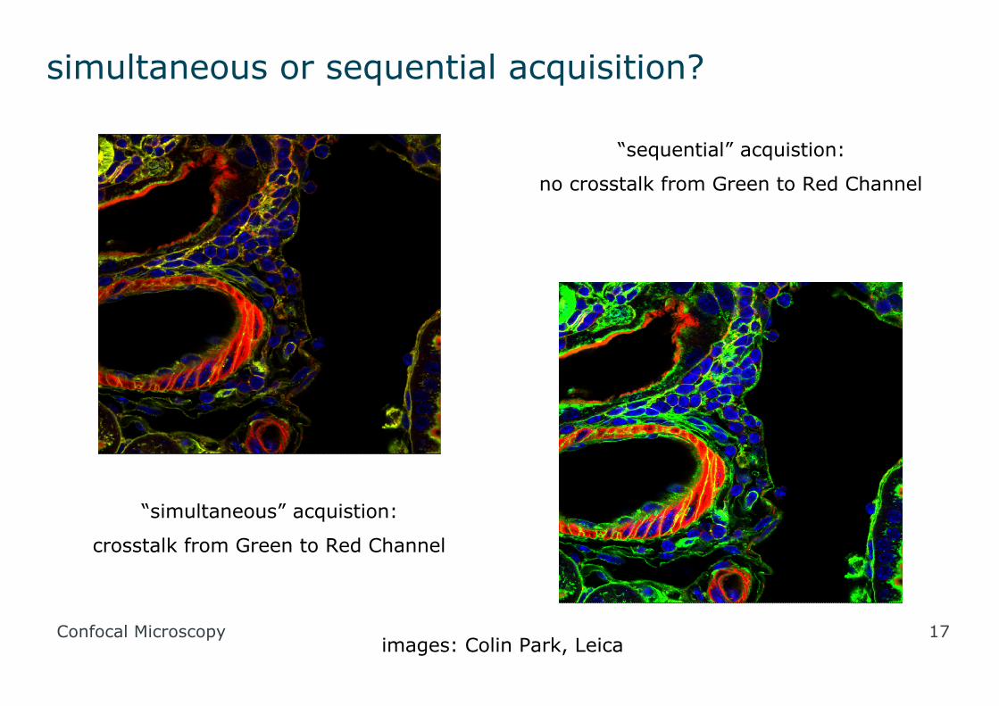
simultaneous or sequential acquisition?
“simultaneous” acquistion:
crosstalk from Green to Red Channel
“sequential” acquistion:
no crosstalk from Green to Red Channel
images: Colin Park, Leica

Confocal Microscopy 18
Leica SP5 LSCM
• inverted Leica DMI600 stand• 9 laser lines (405 to 633 nm)• 4 spectral detectors and transmittedlight detector to >8000 pixel linearresolution• objective range x5 to x100 with opticalzoom• DIC and phase contrast imaging• environmental chamber and 5% CO2 inair supply• resonant scanner• electronic stage with relocation and tilescan function• standard fluorescence microscopy withFITC / TRITC / DAPI compatible filtercubes• 4 MP colour digital camera
Confocal Microscopy 19
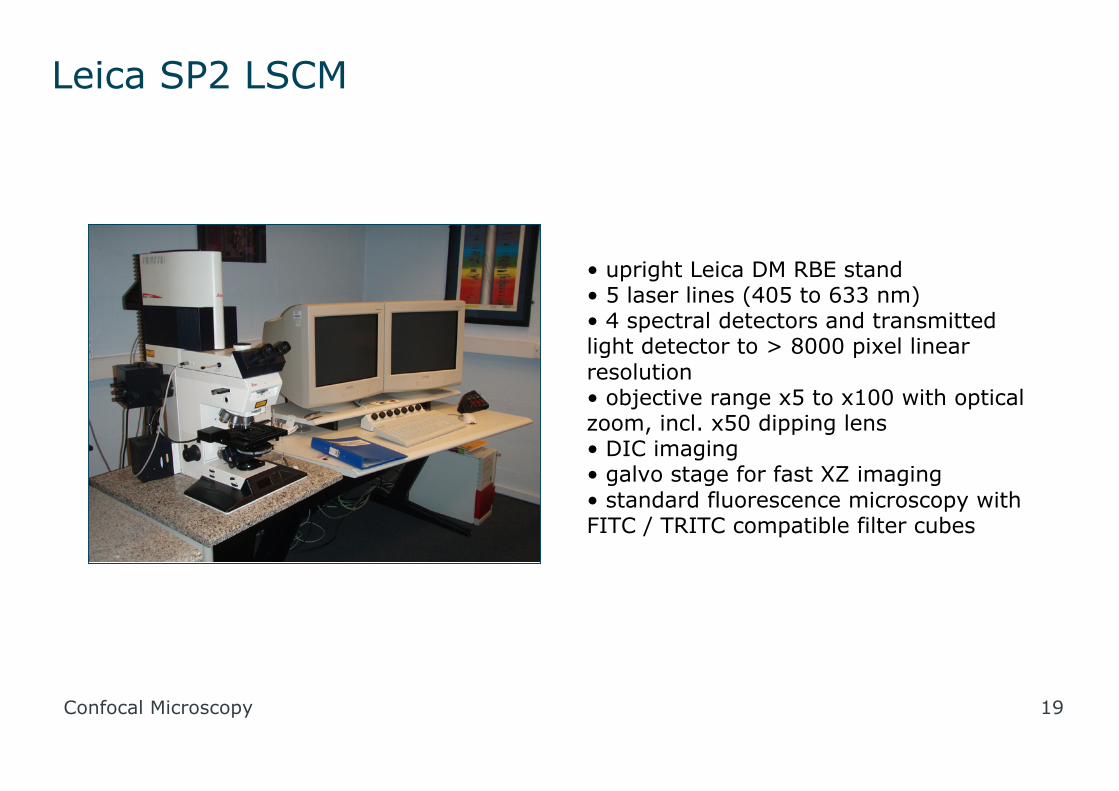
Leica SP2 LSCM
• upright Leica DM RBE stand• 5 laser lines (405 to 633 nm)• 4 spectral detectors and transmittedlight detector to > 8000 pixel linearresolution• objective range x5 to x100 with opticalzoom, incl. x50 dipping lens• DIC imaging• galvo stage for fast XZ imaging• standard fluorescence microscopy withFITC / TRITC compatible filter cubes

Confocal Microscopy 20
confocal image types

Confocal Microscopy 21
(1) animated Z stack
playing back the Z series as a movie can show the relativepositions of fluorescent signals but does not reveal the "wholepicture"
image shows collagen staining on skin basement membrane

Confocal Microscopy 22
(2) maximum Projection
creating a 2D image, pixel by pixelusing the brightest value for thatpixel in the Z series for each colourchannel
recreates the "whole picture" as asharply focused image
it is useful where structuralelements span multiple Z planes asit allows them to be visualised as awhole - eg. neurons in a brain slice

Confocal Microscopy 23
(2) maximum projection
a disadvantage of maximumprojection is the loss of spatialinformation in the Z plane
in this image of bronchialepithelial cells, the maximumprojection reveals that cilia(green) occur on a subset of cellsand that a smaller and differentsubset are mucin (blue) producinggoblet cells
however, there is no way to tellthat the cilia are at the luminalsurface, the blue in the middle ofthe cell and the nuclei (red) arebasal

Confocal Microscopy 24
(3) rotated projection
since the Z series is a 3D dataset, it is possible to calculate what it would looklike if viewed from any other arbitrary angle
it is therefore possible to create image series that show the sample rotatingaround any axis

Confocal Microscopy 25
(4) Z section
since the Z series is a 3D dataset, it is possible to calculate what it would look like if slicedacross at any position
image shows the topology of skin basement membrane revealed by collagen staining: on theleft, a maximum projection (no topology evident): on the right, Z sections through thepositions indicated by the faint white lines reveal a convoluted surface

Confocal Microscopy 26
(5) 3D viewing
rotating a single channel Z series to theleft and right by about 8-10 degrees,and mapping one image to green, theother to red produces an image thatcan be viewed in 3D
image shows willowherb pollen

Confocal Microscopy 27
application types

Confocal Microscopy 28
resonant scanning
Standard scan mode:
512 x 512 pixel scan = 2-3 fps
Resonant scan mode:• true confocal scanning• up to 1024 x 1024 pixels• up to 5 channels• 512 x 512 pixel scan = 25 fps• 512 x 32 pixel scan = 250 fps• 512 x 1 pixel scan = 16,000 fps• useful for calcium imaging, musclecontraction and other rapid processimaging
image: Leica Microsystems

Confocal Microscopy 29
FRET- fluorescence resonance energy transfer
a method to study inter-molecularinteractions at the 1-10nm scale bytransfer of energy between flurochromes
if donor and acceptor flurochromes arephysically close enough, the energyemitted by the donor is not released asdonor fluorescence but excites acceptorfluorescence
images: Leica Microsystems and AAAS

Confocal Microscopy 30
FRAP fluorescence recovery after photobleaching
a method to study the rate ofdiffusion of fluorescentmolecules in fluid media(cytoplasm, membranes etc.)
fluorescence in a specifiedregion of interest is bleachedby intense excitation and therate at which freshfluorescence diffuses back intothe bleached region isdetermined
images: Leica Microsystems, BBSRC Imaging Facility, Daresbury

Confocal Microscopy 31
reflectance mode
images: TaiCaan Technologies