congestion recognition in mobile networks
TRANSCRIPT

Rami Alisawi
Congestion Recognition in Mobile Networks
Helsinki Metropolia University of Applied Sciences
Master’s Degree
Information Technology
Master’s Thesis
15 May 2015

Abstract
Author(s) Title Number of Pages Date
Rami Alisawi Congestion Recognition in Mobile Networks 53 pages 15 May 2015
Degree Master’s degree
Degree Programme Information Technology
Instructor Ville Jääskeläinen, Principal Lecturer
Smartphones have proven to be popular among people around the world, due to a long list of features and capabilities. Such great benefit will multiply once internet connectivity is available. Mobile phones operating systems are evolving quickly to meet end user ex-pectations, furthermore, operating systems typically include a market or store where mil-lions of mobile applications are available and can be easily installed. The growth of the number of applications, smartphone users and the number of applications installed by a single user is increasing the load on the mobile network, given that most of the applica-tions require internet connectivity to function. The increased load can evolve into conges-tion that can be felt by users, for example, it will take longer time to load a web page. The goal of this study was to come up with an algorithm that is able to detect congestion in mobile network as it happens. The implementation of the algorithm runs autonomously in a smartphone, where it analyses the traffic, takes samples, and collects data about network towers location. In order to validate and test the algorithm, Android implementa-tion of the algorithm was developed in addition to a supporting web server. The web server was used to provide storage and real-time view on algorithm calculations. The Android implementation got executed over all three Finnish mobile network operators, and a mobile network simulator box. The algorithm has proven to be novel and has led to a granted patent in the US. Further-more, the study concluded that real-time congestion detection can be extremely benefi-cial for mobile operators where they can get insights from the user prospective, in addi-tion to the countless cases where application developers can alter their application con-nectivity logic according to congestion situations. Additional research could be conducted using the algorithm and the implementation de-scribed in this study. For example, to build an application to compare radio access per-formance between operators in different areas, so end users can pick the operator with the best quality of service in their areas.
Keywords LTE, Congestion, Networks, Mobile, HSPA, UMTS, Android, RRC, RAN
Contents
Abstract
Table of Contents
Abbreviations
1 Introduction 1
2 Background 3
2.1 Mobile Device as Voice and Data Transceiver 3 2.2 Circuit-switching (CS) and Packet-switching (PS) 3 2.3 IP Based Networks End-to-end 4 2.4 Packet Encapsulation 5 2.5 Modern Mobile Operating Systems 5 2.6 Mobile Applications Explosion 6 2.7 Data Plane and Control Plane 6 2.8 Radio Resource Control 8
2.8.1 Inactivity Timer and Battery Life 8 2.8.2 RRC States in UMTS 9 2.8.3 RRC States in LTE 11
2.9 Signal Power and Noise Ratio 11 2.10 Signalling Messages 12
2.10.1 Connection Establishment 12 2.10.2 System Information Blocks 14
2.11 Mobile Data Connectivity in Practice 15 2.12 Typical Mobile Traffic Types 16 2.13 Effect of Keep-alive Mechanism on Networks 17 2.14 Mobile Traffic Congestion 18
3 Targets and implementations 20
3.1 Congestion Recognition Algorithm Targeted Features 20 3.2 Sample Definition 22 3.3 Congestion Recognition Algorithm Inputs 23 3.4 Congestion Recognition Algorithm Components 24
3.4.1 Configuration Engine 25 3.4.2 Setup Time Calculator 26 3.4.3 Congestion Detection Engine 26 3.4.4 Congestion Data Logger 31 3.4.5 Congestion Reporting Agent 31

3.4.6 Report Analysing Agent 31 3.5 Collecting Samples 32 3.6 Android Implementation 33
3.6.1 RRC State Broadcasting Service 38 3.6.2 Congestion Recognition Mobile Application 40
3.7 Real-time Monitoring Web Application 42
4 Results and Analysis 46
4.1 Anritsu Mobile Network Simulator 46 4.2 Finnish Operators (Elisa, Sonera, DNA) 48
5 Conclusion and Recommendations 50
5.1 CRA for Mobile Network Operators 51 5.2 CRA for Mobile Application Developers 52 5.3 CRA for Mobile Operating Systems 52
References

Definition of terms and abbreviations
VoIP Voice over Internet Protocol
GSM Global System for Mobile Communications, also known as 2G
UMTS Universal Mobile Telecommunications System, also known as 3G
LTE Long Term Evolution, also known as 4G
EPS Evolved Packet System
UTRAN Universal Terrestrial Radio Access Network
E-UTRAN Evolved Universal Terrestrial Radio Access Network
HSPA High Speed Packet Access
SIB System Information Blocks
WCDMA Wideband Code Division Multiple Access
IP Internet Protocol
UDP User Datagram Protocol
TCP Transmission Control Protocol
HTTP Hypertext Transfer Protocol
DRX Discontinuous Reception
RRC Radio Resource Control
RACH Random Access Channel
FACH Forward Access Channel
PCH Paging Channel
DCH Dedicated Channel
UE User Equipment, in the scope of this study, it refers to a mobile phone.
CN Core Network
SOC System On Chip
CRA Congestion Recognition Algorithm
CAC Connection Admission Control
NAT Network address translation
PCC Potential Congestion Case
CCC Confirmed Congestion Case
PCD Positive Congestion Decision
Sample Radio packet access ‘setup time’
RSCP Received Signal Code Power
SNR Signal-to-Noise Ratio
IMEI International Mobile Equipment Identity

1
1 Introduction
A mobile network infrastructure works under the assumption that the devices enjoying
packet access offered by an operator would not be in connected mode all at once. That
assumption is what allows the network to serve a larger number of mobile devices. In
the hands of a typical user, a mobile device will alternate between connected mode
and idle mode as he/she surfs the internet and downloads content. What is expected
from the device after the usage session is over is to be in idle mode which will allow the
operator network to release some resources which have been used by that user and
allocate it to another user.
The problem arises when the device is still alternating between connected and idle
mode even without any user interaction. That is a result of the applications being in-
stalled on the mobile device trying to access the internet to communicate with their
content provider to check for updates or to keep the TCP connection alive in order to
push updates or VoIP calls immediately to the user.
Now this represents a challenge to the operator as more and more smart phones are
joining the network and each one of them is loaded with access demanding applica-
tions. This naturally leads to less capacity and a huge signalling load over the network,
which requires expensive hardware updates and investments in new technologies.
That can be easily seen by operators running after 4G LTE-advance network as it pro-
vides bigger packet access capacity. However, that will only buy them some time, as
the number of easy and free to install applications is increasing exponentially.
There are many ways to optimize mobile traffic and prevent overloading the network.
However, there are times that the network is under heavy load. The ultimate goal of
this study is to create an algorithm capable of recognizing congested overloaded net-
works. In order to achieve such a goal, a piece of software running on Android mobile
operating system was developed, in addition to a web application which monitors and
stores algorithm output in real-time.

2
Congestion can happen on the radio part or in the core part of the network. This study
focuses on detecting the congestion in the radio part of the network and can even de-
tect it on cell level. This early detection can take place before reaching the critical con-
gestion level where packet call establishments get rejected.
The congestion detection algorithm lives in the mobile device and takes ‘samples’ and
other measurements as inputs. There are also parameters that can be changed to
tweak its detection sensitivity.
The study starts by explaining mobile network basics then moving gradually towards
describing the background of the problem. In addition to presenting some technical
aspects that are essential for understanding what could cause congestion in mobile
networks.
In the third section the targeted features of the congestion recognition algorithm are
set. In addition, there can be found a detailed description of the algorithm mechanics
and components, which are also available in the patent application. Thereafter, the
implementation journey challenges and solutions are presented with enough details
that enable the reader to replicate the experiment.
The fourth section contains the results of this study. The implementation is put under a
controlled congestion environment using a network simulator machine, where it was
able to autonomously detect congestion. The implementation also reviled some differ-
ences in packet call establishment time between three Finnish operators.
In the last section of this study, it is recommended to include such a congestion detec-
tion mechanism as part of modern mobile operating systems. The benefits will be
shared between mobile operators, application developers and eventually the end us-
ers.
3
2 Background
This section presents current knowledge around the topic and how nowadays practices
are leading to the problem addressed in this research. The following subsections also
provide the necessary understanding on today’s technologies in the fields of network-
ing and mobile data packet access.
2.1 Mobile Device as Voice and Data Transceiver
Initially, the idea behind inventing a mobile device was to provide the user with the abil-
ity to make phone calls wirelessly and to accept phone calls from other network sub-
scribers. Operators carried on the task of establishing the connection and maintaining
the network health and resources. Operators charged their subscribers for these ser-
vices. The more services offered to subscribers, the more profit they would gain. On
the other hand, mobile device manufactures are trying to sell more devices shipped
with smart and advanced operating systems that rely heavily on data exchange with
the internet.
2.2 Circuit-switching (CS) and Packet-switching (PS)
Circuit-switching creates a dedicated channel between at least two subscribers in order
to guarantee the required bandwidth to complete a voice call or exchange a shot-
message. However, it quickly became clear that circuit-switching is not the optimal way
to transmit and handle internet packets. As a result, packet-switching became the clear
path to go forward.
Multiple technologies have emerged to satisfy the need for packet access, most nota-
bly GPRS found in the so-called 2G and UMTS/HSPA found in 3G. Figure 1 illustrates
the technologies and packet domains.

4
Figure 1. Circuit and packet domains [1].
It is noticeable that in 4G or EPS (Evolved Packet Service) even voice service will be
moved from circuit switching to packet switching, which will increase the load for packet
access. The more load the more importance given to congestion detection methods.
2.3 IP Based Networks End-to-end
During the LTE development of new specifications, the goal was to move from UTRAN
to E-UTRAN. It was logical to choose IP packets as mean of transferring information
between mobile devices and RAN, as the Core Network is already IP based. The Core
Network (CN) would simply act as an Internet gateway for connected mobile devices.
The different mobile network architectures, on a general level, are shown in Figure 2.
Figure 2. Radio Access Network from GSM to LTE [2].

5
In 3G’s UTRAN some of the services related to packet access were still relying on cir-
cuit switching, however, in 4G’s E-UTRAN it is all IP based even for signalling and con-
trol messages.
2.4 Packet Encapsulation
The main characteristics of a typical IP packet are its source address, destination host
and payload. The payload is usually occupied by a transport protocol where its header
would contain more details such as source and destination ports. Transport protocol
payload can be application specific data or some other protocol, for example, HTTP.
This flexible and multi-layered structure of IP is the reason why telecommunication in-
dustry is heavily based on it.
Figure 3. Packet encapsulation example for UDP [3].
In most cases application developers are dealing with the ‘Data’ in ‘Application’ layer as
seen in Figure 3. The ‘Transport’, ‘Internet’ and ‘Link’ layers are being taken care of by
the operating system. This packet’s ‘Data’ shown in Figure 3 could be carrying a seg-
ment of bytes as part of a VoIP call.
2.5 Modern Mobile Operating Systems
There has been a noticeable development in mobile operating system features. Con-
currency and background multithreading are available in any modern OS, in addition to
powerful computing abilities that can under-clock its frequency to reduce power con-
sumption. These set of feature have enabled mobile applications to be in always-on

6
mode, and easily communicating to their content providers in the background using
packet access. While such features are pretty useful and attractive to the end user,
modern operating systems have caused extra load over the radio network. The reason
is, obviously, mobile application developers who are always aiming at customer satis-
faction and they will happily utilize all the communication resources available to reach
their goal.
Operating systems have also provided developers with facility to wake up the device
periodically from deep sleep, which will turn CPU on, in order to complete some tasks.
Usually such tasks include sending a packet to keep the connection alive to its content
server through Internet infrastructure. Otherwise, the connection’s socket information
will get a lower priority in networking routers memory and finally it is dropped.
2.6 Mobile Applications Explosion
All major mobile operating systems have introduced easy ways for users to download
applications, which resulted into billions of mobile application downloads ‘More than 60
billion total apps have been downloaded…That puts Apple about on par with the An-
droid’ [4]. There is nothing stopping the user from downloading more and more applica-
tions, especially, when mobile hardware specifications are getting better and there are
huge numbers of free of charge applications to try out. ‘Nielsen estimates that in 2012
the average number of apps in a mobile device was 41, compared to 32 in 2011.’
[5]P.8.
It is quite appealing to discover new applications; however, in many cases a user would
not really bother to remove the applications, which are no longer in use. This has impli-
cations, which will be explained further in this study.
2.7 Data Plane and Control Plane
Date plane is the channel where all user specific data goes. In order to have sustaina-
ble data flow between a mobile device and Internet servers, there is another data being
exchanged to achieve that, which is going over control plane as shown in Figure 4.
Let’s say a user is downloading a video from some server on the internet, it will be go-
ing over the data plane and the user might be charged for those bytes being trans-

7
ferred, however, there is another kind of data going over the control plane to insure that
data plane is functioning properly.
Figure 4. Control plane is essential part for data flow [5]
In matter of fact, it is not possible for data to be carried over the data plane unless sig-
nalling messages have already been exchanged over the control plane. Data being
transferred over both channels – control and data - composes mobile traffic ’The data
plane accounts for most traffic, typically over 95% of it’ [5], however, different patterns
can be seen depending whether the device is being actively used or not as shown in
Figure 5.
Figure 5. Majority of the traffic is for signalling when device is not under active use [5] P.5.
It is worth noting that for small short burst of user data, it is possible in 3G networks
that the user data gets carried over RACH/FACH-channels, even though such chan-
nels were designed to carry signalling messages.

8
2.8 Radio Resource Control
Radio modem in a mobile device cannot be on all the time, because it would drain mo-
bile phone battery and operator resources, therefore, radio modem can be on idle
mode most of the time. In idle mode, the mobile device is still considered to be reacha-
ble and recognized by the network. A switch to fully operational mode happens once
voice call or packet access is needed. In any case, there are some signalling messag-
es being monitored all the time, for example, signal strength updates of surrounding
cells.
There can be only one state for a connection in a given single mobile device. Alternat-
ing between states always requires special signalling messages and processing by
network components to reserve and release resources. Such procedure is one essen-
tial element for this study in the efforts of detecting congestion.
2.8.1 Inactivity Timer and Battery Life
Inactivity timer is a time value which starts ticking once there is no uplink or downlink
user data going on, for example, in case browsing a web page, typically there will be
multiple HTTP requests and responses which will definitely make radio modem in a
fully operational RRC state. Once the web page is displayed and no user traffic is on-
going, inactivity timer will start ticking. Afterwards there are two possibilities; it is either
the user will click on some web link generating some more traffic which will reset the
timer or the user will not click on any link letting the timer to expire. Once the timer ex-
pires, resources will be released and radio modem can demote to a lower state to safe
energy and battery life. Timer value is set by network operator, where a bigger value
will result in less signalling load, since one radio session will most likely serve bigger
amount of user data, on the other hand, smaller timer value, will generate more signal-
ling messages due to multiple radio connection establishment for the same amount and
pattern of user data.
It is easy now to realize the trade-off between increasing the inactivity timer and net-
work signalling load. Mobile manufactures prefer the smallest timer value possible, to
increase their device’s battery life, while operators prefer a bigger value since connect-
ed time is not as big of a concern as signalling load. There is also a third element,
which is user experience, since loading a web page while the radio already has packet

9
session established is faster than waiting for the radio to establish packet session, then
data transfer would start.
Figure 6. RRC states power consumption in UMTS [13].
The UDP packet seen in Figure 6 above had to face a delay in time for few seconds till
the radio state promoted from IDLE to DCH, only then the UDP packet made it out of
the mobile device, this delay is one essential parameter for congestion detection algo-
rithm.
2.8.2 RRC States in UMTS
Once a mobile device is switched on, it will go through initial attach and when it is suc-
cessfully camping on some nearby cell, RRC state will be on IDLE mode. Once there is
incoming or outgoing packets there will be RRC Connection Establishment procedure,
where it will promote the RRC state from IDLE to CELL_FACH or CELL_DCH depend-
ing on the traffic volume and network settings. The different RRC states in UMTS are
shown in Figure 7.

10
Figure 7. RRC states with green arrows showing possible promotions and demotions [7].
Once there are no more incoming or outgoing packets for some time –usually matter of
seconds- there will be a state demotion from CELL_DCH or CELL_FACH to URA_PCH
or CELL_PCH which are low power consumption states and no user data can be trans-
ferred, however, it is still faster to promote the state back to CELL_DCH or
CELL_FACH than promoting from IDLE. If there is still no data activity for extended
period of time –usually around half an hour- there will be demotion to IDLE.
The main difference between FACH and DCH is that the later one has a dedicated
physical channel and transmit measurement reports, which help to get data transfer
very reliably, therefore, HSPA variants are implemented to operate over DCH.
The above was a sort of mitigation for UMTS inactivity timers and their effect of battery
life in 3GPP release8, where Fast Dormancy (FD) was introduced. FD will allow radio
modem to ask for connection release SCRI message that will let the device demote to
PCH instead of IDLE.

11
2.8.3 RRC States in LTE
There is noticeable complexity reduction in many aspects in LTE. RRC states are sim-
plified to be two states, making promoting to connected state faster instead of the –
mostly- gradual promotion in UMTS (see Figure 8).
Figure 8. RRC states in LTE are only two RRC_Conncted and RRC_IDLE [9].
In order to simulate FD and the missing PCH state, there was increase focus on using
DRX techniques namely Short DRX and Long DRX cycles to make power consumption
during inactivity time more efficient. Looking at different operator settings, there is still
no wide adaptation for DRX in LTE, which resulted in shorted battery life. Some might
argue that eliminating RRC state CELL_FACH and the possibility for RACH/FACH to
carry user data was not the best thing to do in LTE. Since in LTE there is no state
where transferring relatively insignificance small burst of data is feasible without getting
dedicated resources and higher level or energy consumption.
2.9 Signal Power and Noise Ratio
A mobile device includes a chip that always measures the incoming signal strength and
background noise. It is the main measure for a mobile device to do a handover in fa-
vour of other cells with a stronger signal power. A weak signal power or high noise lev-
els does not necessarily correlate with congestion. Under poor signal conditions a
packet access call will either make it or not, while under congestion the packet call will
make it under good signal conditions, however, the call will face delays.

12
2.10 Signalling Messages
Messages and updates are being exchanged over the control plane as long as mobile
device is switched on; they handle all aspects for mobile connectivity. For simplicity
sake, throughout this study, RRC states (IDLE, PCH, FACH) in 3G and (RRC_IDLE) in
4G are called ‘LOW’ RRC state, while, (DCH) and (RRC_CONNECTED) are called
‘HIGH’ state.
2.10.1 Connection Establishment
Connection establishment occurs, for example in UMTS, when RRC is on low state and
there is incoming or outgoing traffic to mobile device (User Equipment), however, pro-
cedure is slightly different, depending on traffic direction.
A. Mobile device initiated connection
A typical case would be a client application, which is trying to reach its content pro-
vider, could be based on user interaction or not. Operating system’s network stack
will compose the required packets according to application’s transport protocol.
Packets will reach radio network interface where they will start to fill radio modem
buffer. If there are only few packets or if they are small size, then they might get
transferred using RACH uplink of CELL_FACH and that would not trigger full promo-
tion to CELL_DCH. However, in most cases, packets have big payload which will fill
the buffer instantly, in such case, radio modem will immediately start sending signal-
ling messages as shown in the Figure 8.

13
Figure 8. Signalling messages exchanged in 3G [6] p.168.
Packets will be transmitted once transition to DCH is completed. It is noticeable that
RACH is always used for uplink (outgoing) messages and FACH is used for down-
link (incoming) messages, both RACH and FACH are under CELL_FACH state.
B. Network initiated connection
A typical case would be a content provider pushing data to its client mobile applica-
tion. Instant messaging mobile applications are the most common ones, for exam-
ple, if someone sends a picture to his friend, the picture will be first uploaded to
server side, which in turn will pass it to its intended destination. The picture packets
will travel through internet routers, middle boxes and operator’s core network till it
reaches RNC where such large packet will fill up network side RNC’s buffer. In such
case of RNC full buffer, RNC will decide to promote DCH connection as illustrated
Figure 9.
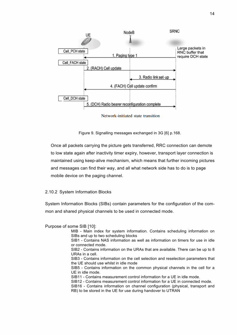
14
Figure 9. Signalling messages exchanged in 3G [6] p.168.
Once all packets carrying the picture gets transferred, RRC connection can demote
to low state again after inactivity timer expiry, however, transport layer connection is
maintained using keep-alive mechanism, which means that further incoming pictures
and messages can find their way, and all what network side has to do is to page
mobile device on the paging channel.
2.10.2 System Information Blocks
System Information Blocks (SIBs) contain parameters for the configuration of the com-
mon and shared physical channels to be used in connected mode.
Purpose of some SIB [10]: MIB - Main index for system information. Contains scheduling information on SIBs and up to two scheduling blocks SIB1 - Contains NAS information as well as information on timers for use in idle or connected mode. SIB2 - Contains information on the URAs that are available. There can be up to 8 URAs in a cell. SIB3 - Contains information on the cell selection and reselection parameters that the UE should use whilst in idle mode SIB5 - Contains information on the common physical channels in the cell for a UE in idle mode. SIB11 - Contains measurement control information for a UE in idle mode. SIB12 - Contains measurement control information for a UE in connected mode. SIB16 - Contains information on channel configuration (physical, transport and RB) to be stored in the UE for use during handover to UTRAN

15
SIB18 - Contains PLMN identities for neighbouring cells to be considered for use by a UE that is in either idle or connected mode
SIB3 includes reselection parameters that effect mobile device cell selection. Conges-
tion can be on cell level and alternating between a congested cell and a normally func-
tional cell will definitely affect any tool that is trying to detected congestion.
2.11 Mobile Data Connectivity in Practice
Modern mobile operating systems offer some means to check mobile data connectivity
status, for example, in Android OS there is a ConnectivityManager and here is the best
API offered to check connectivity:
NetworkInfo activeNetwork = connectivitmanager
.getNetworkInfo(ConnectivityManager.TYPE_MOBILE);
boolean isConnected = activeNetwork.isConnected();
NetworkInfo reference [11]
Quoting from (isConnected) method description that it “Indicates whether network con-
nectivity exists and it is possible to establish connections and pass data”, however, this
does not mean that the data will reach its destination server, as there could be conges-
tion in UTRAN or in CN. On the other hand, iOS provides a slightly better approach
with its Reachability API, where they test sending IP packets to a well-known and de-
fined host - www.apple.com by default.
However, neither of the most used mobile operating systems Android and iOS, offers
an easy to fetch information about network health, even thought they have access to
the traffic for all the applications. That leaves the app developer to implement own test-
ing with some server, for the pure purpose of knowing how good the network connec-
tivity is. Such method will always be related to application own traffic. On the other
hand, the operating system can see the combined traffic of all the applications, which
means more knowledge can be obtained from such data. This study recommends that
mobile operating systems should share the knowledge about connectivity conditions
with all the mobile applications that are interested to know it.

16
2.12 Typical Mobile Traffic Types
Nowadays, mobile traffic of many mobile applications can go under one of the following
categories according to their connectivity demands:
• Always connected: such applications live and breath on connectivity, their first
task is to stay connected to their server, for example, Google services which is
installed in almost every Android OS likes to keep a connection to Google’s
servers all the time and to keep that connection alive, there it sends a TCP
packet every twenty minutes. Chatting applications also go under this category,
for example, Viber application for instant messaging and voice calls, must
maintain a connection so the incoming messages arrive without delay, of
course, to achieve that a keep alive packet is sent every ten minutes.
• Semi connected: for those applications, staying connected is not vital for their
functionality, weather applications can connected every now and then to get
latest weather reports. Some other applications, needs to sync the latest offers
and upload some data only when WIFI is active. There is no need for keep
alive since the connection can be gracefully closed once the data exchange is
done.
• Connected on demand: internet browser makes good example in this category
where it is connecting only when there is a demand and request by the user.
Which means that there is no need for a long lasting connection.
One important consideration is that mobile traffic is moving away from HTTP. Tradi-
tionally, HTTP has been known to be the internet language. HTTP is just strings
streamed over TCP and those strings have special meaning for a browser. The brows-
er can translate those strings into shapes and well-formatted text. However, in the re-
cent years mobile traffic is shifting noticeably away from HTTP, while chatting applica-
tions are taking over with their custom protocols over TCP or UDP. Even lesser time is
spent on web browsing over the small mobile screen, and more time is spent in instant
messaging applications.

17
2.13 Effect of Keep-alive Mechanism on Networks
The typical HTTP traffic can be considered network friendly, since in its basic form the
connection is closed as soon as HTTP documents and resources are downloaded.
However, there are many approaches where they use HTTP for a long lasting tasks
and employs some keep alive mechanism, in addition to the always-connected applica-
tions which have their own keep alive mechanism going on. The reason behind the
keep-alive mechanism is that the connection would be broken without them. The rea-
son is that router and switches have limited hardware resources and cannot keep rout-
ing tables and information about all the connections going through them, so they start
to drop the old connections in favour of new ones, unless a packet goes though the old
connection, which make the connection gain priority again, as it is considered to be still
active and needed. That is why mobile applications wishing to keep their connection
alive will have to keep sending keep-alive packets typically with very small payload just
to prevent the connection information from being dropped in some router or switch.
It is easy to imagine the effect of millions of keep-alive packets going at specific times
on the operator network. The pressure is greater on the Radio Access (RAN) than on
Core Network (CN), since there are much more signalling and computer resources
consumed to promote the radio connection in case it was idle than to forward the pack-
et through CN routers and switches. It is worth to mention that the pressure on the
RAN would be much smaller if the radio was already promoted and in active state, that
is why Android in version Lollipop introduced new API to let applications know about
the good moment to transmit packets, since the radio is already active.
ConnectivityManager. isDefaultNetworkActive ()
Return whether the data network is currently active. An active network means that it is currently in a high power state for performing data transmission. On some types of networks, it may be expensive to move and stay in such a state, so it is more power efficient to batch network traffic together when the radio is al-ready in this state. This method tells you whether right now is currently a good time to initiate network traffic, as the network is already active.[12]
This will ease the problem but it will not make a noticeable difference until it is widely
adopted.

18
Figure 10. ‘Queue background data’ option in Sony Android
Sony mobile has customized their Android ROMs to include a traffic shaping feature
that forces background data and keep-alive packets to be delayed and bundled togeth-
er (see Figure 10). This method might sounds like a good idea, however, it is prone to
break applications functionality since most applications have predefined timeouts. In
case Sony power management agent delayed a packet more than the predefined val-
ue, the app would think that it lost connectivity, which force a more harmful, and ag-
gressive retry mechanism.
The only way for the operator to cope with the problem is to install and upgrade hard-
ware to handle the load. Deploying microcells (less than two kilometres) and picocells
(less than 200 meters) is targeted to ease and distribute the load.
2.14 Mobile Traffic Congestion
Mobile traffic goes through radio wireless element and network element. Network con-
gestion is well known issue and there are many methods to identify it. Mobile traffic is
facing such network congestions as well, however, there is another type of congestion
that is unique only to mobile traffic. Radio access congestion strikes early on before
any network or routers, it even accrues before any packets leave the device.

19
Most of commonly used protocols incorporate some kind of algorithm to detect and
deal with network congestion. Ethernet, for example, employs exponential back-off
which prevent frames collision by retransmitting the frame from each host at random
timings in range of milliseconds. The famous TCP has a set of techniques under its
congestion-avoidance algorithm, namely the ‘slow-start’ and ‘congestion window’. They
work together to limit the number of packets that has been sent and did not get
acknowledged.
On the other hand, there is not as much of advanced algorithms and methods to detect
radio access congestion. What is currently in operating is Connection Admission Con-
trol (CAC) algorithm, which insures a predefined level of Quality of Service (QoS) for a
number of connections and if the number of connections exceeds the bandwidth avail-
able, the new connections will get rejected. A connection for CAC could be voice call
via circuit switching or a video downloaded via packet switching, this means that at the
nodeB and RNC level, they can be under huge load and CAC never kicks in or interfere
to do anything. In such cases the nodeB or/and RNC can send RRC message ‘connec-
tion reject’ when they are running low on CPU and other resource, which is typically a
result of heavy signalling load.
This study focuses on detecting the congestion in nodeB/RNC before reaching the crit-
ical level where they start to reject packet call establishments, while congestion in CN
is out of the scope.

20
3 Targets and implementations
One could do a lot to optimize how IP packets are transmitted over radio signals; how-
ever, this study focuses on finding a way to detected congestion in packet access with-
in UTRAN or E-UTRAN. The congestion detection algorithm lives in mobile device and
takes ‘samples’ and other measurements as inputs. There are also parameters that
can be changed to tweak its detection sensitivity.
In order to verify and collect data for analysis, an Android implementation of the algo-
rithm was developed, in addition to server side software to store and to present algo-
rithm internal calculations in real-time.
3.1 Congestion Recognition Algorithm Targeted Features
In order to leverage congestion recognition algorithm (CRA) value, the following prop-
erties were set as goals:
• Independent: once an implementation for this algorithm is operating on some
mobile devices, it is not allowed for any running instance to assist by sharing in-
formation with another instance. While it seems greatly beneficial if inter-
communication were allowed, it would be ironic for a solution that is trying to
ease and help congested network to make some connections to gather infor-
mation. It is not even guaranteed that a connection would be successful under a
congested network. It would be a critical failure point if the algorithm is relying
on some input from a remote resource, hence, all data and inputs must be col-
lected locally. This implies that each instance of the algorithm is operating inde-
pendently and taking its own decisions, totally isolated from other instances,
servers and network health providers.
• Real time: most of the algorithm’s operations must be going on in real-time, for
example, sample collections, RRC state tracking and making a final decision to
block a portion of background traffic. However, log uploading and similar non-
urgent functions should be deferred to more favourable conditions, such as, de-
vice is in charging mode.

21
• Based on user equipment: it would be a showstopper if there were a need for
network side UTRAN to have some special support for this solution to work. It is
well known that pushing some feature or request ahead needs a big player in
the communication industry and it takes years till it is part of a next release
specification. That is the reason why, the solution in this study can be fully run
on mobile device only.
• Runs on all chipsets: radio modem chipsets have a variety of debugging infor-
mation that can increase algorithm accuracy. However, the algorithm should be
able to function without any chipset dependency. Such additional input can be
decided on during implementation according to the use case, device, operating
system and chipset. Qualcomm makes the most commonly used chipset out
there. While it is mostly closed source, they provide Qualcomm eXtensible Di-
agnostic Monitor (QXDM) where an extensive volume of data is available, for
example, all RRC messages can be collected as seen in Figure 11.
Figure 11. Example of logs generated by QXDM
The red highlighting in the above figure, shows the exact signalling message
being exchanged to establish and teardown a connection.

22
• Adjustable Sensitivity Parameters: there could be use cases where it is pre-
ferred to tweak how sensitive the algorithm is in detecting congestion. For ex-
ample, if the use case is to measure user experience then tweaking sensitivity
settings to be more aggressive will generate reports around any turbulence in
packet access.
The mentioned goals mean fewer restrictions on where the algorithm can run. It is
feeding on readily available information and bringing great added value in return.
3.2 Sample Definition
A mobile device sends and receives packet traffic frequently; such packets relation with
radio modem state can expose the following possibilities:
Radio state / traffic direction Low state High state
Incoming A B
Outgoing C D
Possibilities ‘B’ and ‘D’ are not useful for CRA, since it is focused on detecting conges-
tion in RAN or cell. There are some other tools for detecting problems in CN where the
focus is on the traffic while the radio is already on high state.
Possibilities ‘A’ and ‘C’ are candidates for sampling; however, it is only possibility ‘C’
where CRA can take a sample measurement, because it can get the packet timestamp
once it is processed by OS/Kernel, while in case ‘A’ the timestamp of when the packet
has reached RNC, is impossible for CRA to know, since it operates in the mobile de-
vice.
The order of events that allow the transition from idle mode to connected mode is
shown in Figure 12.

23
Figure 12. Possibility ‘C’ value is T1. [15]
Simply put, a sample is the time duration (T1 as in Figure 12), which is the difference
between the time stamp of a request for packet access and the time stamp of when the
packet access is actually granted.
3.3 Congestion Recognition Algorithm Inputs
In order to get CRA working, the following inputs and requirements must be met:
• Intercepting the traffic or generating it: the time stamp when the traffic was gen-
erated is needed for the sample calculations. The ideal way is to intercept the
traffic that is normally transmitted while the user is browsing the internet and en-
joying packet access. Intercepting the traffic can be done using (iptables) where
some (NAT) rules can tunnel the traffic to local software where it acts like a
proxy. Another alternative to achieve the same thing is to implement fake VPN
client. However, if intercepting the traffic is not possible due to lack of permis-
sions or for other technical limitation of the hosting platform, then a simple func-
tion can be integrated to generate some traffic and in that case getting the time-
stamp of the own generated traffic is pretty easy.
• Cell-id and location area code: all samples measured are associated with their
respective CID and LAC. This is needed so the algorithm will know it if facing a
RAN level congestion or only single level congestion, it is also good to know if
some samples are higher or lower in value only under that cell. All those values
will be included in the aftermath reports. Another benefit is that the congestion

24
detection algorithm can notice if the cell id is changing fast which means that
the mobile device is on the move and a lot of handover is happening. This helps
the logic to avoid some creating a Potential Congestion Case (PCC) and wait till
it can collect a fixed number of samples when the mobile device is not on the
move, that fixed number is part of the parameters which can be tweaked. The
raw information about LAC and CIDs of current and neighbouring cells is usual-
ly easily accessed without a trouble, it might need to ask for a permission, but it
is easily obtained in the most common mobile operating systems.
• Signal strength: it is easy value to obtain for the currently camped on cell. Un-
der bad signal strength the algorithm will be more doubtful about its decision,
since a bad reception might be the reason for the abnormal and extreme val-
ues.
One of the beneficial features that CRA offers is to have few requirements and inputs.
It is well known that more requirements and inputs may restrict the algorithm imple-
menter from deploying it to a wider set of devices or operating systems.
3.4 Congestion Recognition Algorithm Components
There are multiple sub components and logical units working together to detect con-
gestion. Figure 13 shows an overview:
Figure 13. CRA components overview [15].

25
More detailed information covering each component function is provided in the follow-
ing sections.
3.4.1 Configuration Engine
Here are all the parameters and configuration values that affects CRA functionality and
decision-making:
• Setup time standard deviation allowance (st_std): will allow us to set how ag-
gressive the logic should be in making a Potential Congestion Case (PCC), ze-
ro means most aggressive.
• Number of confirmed congestion cases (num_ccc): will allow us to set how ag-
gressive the logic should be in triggering the Positive Congestion Decision
(PCD), according to the number of Confirmed Congestion Case (CCC).
• Size of Setup Time records (st_stack): is like the logic memory, and how quickly
the logic can adapt to another area setup time, smaller number means shorter
memory.
• SNR normal values range (snr_rng) for RSCP value: This range is needed
while deciding on each PCC. Example of values for UMTS:
RSCP (Signal power) SNR (Signal-to-noise ratio) -50...-70 0...-5 -70...-85 -3...-7 -85...-95 -5...-10 -95...-105 -7...-14 -105...-115 -9...-16 -115...less -11...-18
• Number of cells to trigger (pcd_trg): how many cells must exceed the num_ccc
(Number of confirmed congestion cases) in order to trigger PCD (Positive Con-
gestion Decision). If the number is bigger than one, it means CRA will target
congestions beyond one cell scope; for example, congestion can be at RNC
level, because confirmed congestion cases are coming from more than one cell.
However, if the number is set to one, then CCC coming from only one cell is
enough to trigger PCD.

26
There are some elements that cannot be parameterized, such as differences between
network operator infrastructure hardware. For example, the performance between
Nokia and Huawei equipment is not exactly the same. This challenge is solved by ad-
aptation feature of the algorithm.
3.4.2 Setup Time Calculator
The setup time calculator measures setup time for establishing a connection with a
base station in the radio access network. The setup time is determined or measured as
the time elapsed between the detection of a data request that requires a radio connec-
tion (or a radio turn on request) and transition of the radio state to a connected state
from idle state in some implementations (i.e., RRC high timestamp - request time
stamp during RRC low or idle) as seen in Figure 12. The radio state information can
be determined or obtained from the radio state detector 277 as seen in Figure 13, for
example, according to exact implementations, the setup time can be measured based
on a radio access bearer setup time, measured as a time difference between transition
to high RRC state timestamp and a request timestamp.
During a radio bearer reconfiguration procedure, a radio bearer reconfiguration mes-
sage is sent by the network to a mobile device, and the mobile device acknowledges
the receipt of the message by sending a radio bearer reconfiguration complete mes-
sage to the network.
3.4.3 Congestion Detection Engine
In the engine resides the core logic, the following points explains how to it can activate
its self and how different components analyse the emerging data:
• The initial setup time stack manager 282 of the congestion detection engine
280 as seen in figure 13, can aggregate a predetermined number of setup time
samples (e.g., 20 samples or another number of samples based on st_stack),
until the stack is full. When the stack is full, the initial setup time stack manager
282 can activate the logic for detecting potential congestion, the flowchart for
activation can be seen in Figure 14.

27
Figure 14. Flowchart showing CRA activation [15]
• The baseline setup time calculator 283 as seen in Figure 13 can be triggered by
initial setup time stack manager 282 to calculate a baseline or reference setup
time from the sample of setup times collected by the initial setup time stack
manager 282. The baseline is calculated as the sum of the average or mean of
the setup times in the initial stack, the standard deviation of the setup times in
the initial stack and the setup time standard deviation allowance (st_std). The
baseline can be determined using a variation of the method above, or any other
statistical method in other implementations. The baseline setup time calculator
283 can be triggered to update its calculation of baseline every time a new set-
up time value is measured by the setup time calculator module 276.
• The potential congestion case (PCC) detector 284 as seen in Figure 13, can be
triggered by the activation of the congestion detection logic when the initial set-
up time stack is full. The potential congestion case detector 284 detects a po-
tential case of congestion by detecting an increase in setup time values com-
pared to the baseline. The setup time values that are longer than the baseline
are stored in a temporary stack of the same size as the initial stack by the tem-
28
porary setup time stack manager 285. The setup time values below the base-
line replace the oldest values in the initial stack (via the initial setup time stack
manager 282). In one implementation, the potential congestion case detector
284 can acquire cell-ID or other base station identifier information and/or loca-
tion area code for each potential congestion case detected. In one implementa-
tion, the cell-ID and/or location area code may be obtained using Attention (AT)
commands used for controlling a device modem. For example, AT+CREG
command returns cell-ID and location area code.
• The confirmed congestion case detector 285 can analyse the potential conges-
tion cases and determine whether the potential congestion cases should be
promoted to confirmed congestion cases. In order to detect confirmed conges-
tion cases from potential congestion cases, the modem of the mobile device
may be queried for reception quality data via the reception quality analyser 286,
for example. In one implementation, using AT+CSQ command, received signal
strength indicator (RSSI) value, which can be mapped to signal condition (e.g.,
marginal, OK, good, excellent or the like), can be determined. Other reception
quality data that can be queried include, for example, received signal code
power (RSCP) and ratio of received energy per chip (Ec/Io). Depending on the
implementation, the modem may be queried for any RRC rejection messages
from the base station by the data connection rejection query module 287, for
example.
• The final or positive congestion case detector 288 can evaluate the confirmed
congestion cases using the attached location area codes, cell IDs and other pa-
rameters (e.g., num_ccc and pcd_trg) to determine and/or verify whether the
network is congested. In one implementation, the congestion pattern detector
289 can examine the cell-IDs and location area codes attached to the confirmed
congestion cases to determine whether the confirmed congestion cases are
concentrated on a few specific cell-IDs or are distributed over many cell-IDs
and/or over multiple location area codes. This pattern of cell-IDs and/or location
area codes associated with confirmed congestion cases can provide an indica-
tion to the final congestion detector 288 that the mobile device is in motion, and
the confirmed congestion cases cannot be reliably used to determine the pres-
ence of network congestion. For example, if the analysis of the congestion pat-
tern indicates that a large number of confirmed congestion cases are concen-
trated on a one or two cells, the final congestion case detector 288 can make a

29
positive or final congestion decision. By way of another example, if the pattern
of the confirmed congestion cases indicates cases associated with multiple
cells belonging to different location area codes, the final congestion case detec-
tor can determine that the mobile device is in motion, and a final decision can-
not be taken.
The congestion detection engine logic - after being activated - can be summarized in
the following flowchart seen in Figure 15:

30
Figure 15. CRA logic flowchart [15]
After a final positive congestion decision has been triggered, a smart blocking policy
can be applied. However, that is only one suggestion. Further or alternative actions can
be taken depending on business needs, more on that is presented in the recommenda-
tion section of this study.

31
3.4.4 Congestion Data Logger
Congestion data logger logs all data related to congestion detection. For example, the
congestion data logger 290 can log data request timestamps, radio turn on timestamps,
setup times in association with corresponding cell-IDs and location area codes, recep-
tion quality measurements (e.g., RSCP, Ec/Io, RSSI, and the like), final congestion
detection data (e.g., final congestion detection date, time, cell-IDs, location area code,
network operator (e.g., Sonera, Elisa, Verizon, AT&T, etc.), and the like), configuration
parameters and/or settings, device information.
3.4.5 Congestion Reporting Agent
The reporting agent uploads logged congestion data to the server-side proxy, the host
server, and/or the log storage and processing service. The agent 292 may be config-
ured to generate and send congestion reports to the LSPS or other remote entities pe-
riodically, or whenever a connection is available. In one implementation, the congestion
reporting agent 292 can crate congestion reports using one or more templates.
Log uploading is trigged when a predefined number of logs or time limit has been
reached, however, the logs patch has to wait for two conditions, first one is that the
device has to be on charger in order not to effect battery life; the second condition is
WiFi connection or free-riding on already established packet access radio connection,
with the aim to avoid being responsible for imitation the radio connection.
3.4.6 Report Analysing Agent
All the report are handled in server side application, where they get plotted on a map
(see Figure 16) showing how many CRA instances have reported congestion, the re-
ports have information about Location Area Code ‘LAC’ and a list of connected cell-ids.
CRA reports analyses has a critical role, where it serve as the last filter in the logic to
eliminate false positives
32
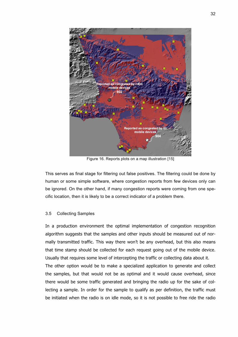
Figure 16. Reports plots on a map illustration [15]
This serves as final stage for filtering out false positives. The filtering could be done by
human or some simple software, where congestion reports from few devices only can
be ignored. On the other hand, if many congestion reports were coming from one spe-
cific location, then it is likely to be a correct indicator of a problem there.
3.5 Collecting Samples
In a production environment the optimal implementation of congestion recognition
algorithm suggests that the samples and other inputs should be measured out of nor-
mally transmitted traffic. This way there won’t be any overhead, but this also means
that time stamp should be collected for each request going out of the mobile device.
Usually that requires some level of intercepting the traffic or collecting data about it.
The other option would be to make a specialized application to generate and collect
the samples, but that would not be as optimal and it would cause overhead, since
there would be some traffic generated and bringing the radio up for the sake of col-
lecting a sample. In order for the sample to qualify as per definition, the traffic must
be initiated when the radio is on idle mode, so it is not possible to free ride the radio

33
session that is already up. The sole advantage of this approach is that it can work out
of the box and start working as soon as it is installed, therefore, no need for intercept-
ing any traffic or any special permission. The frequency for taking a sample can be
every twenty-minute at least to provide enough data for congestion recognition algo-
rithm to learn and study what is normal and look for anomalies.
3.6 Android Implementation
In order to place congestion recognition algorithm into practice, an implementation has
been developed on top of Android platform. The first challenge was in capturing the
radio RRC state accurately, such data is not available within Android API. After doing
some research around the problem, it seems that other researchers [11] are relying on
packet dumps and power monitors plugged to a mobile phone. Combining both data
sources to develop a module that is based on a timer to estimate dormancy timer val-
ue. Using the timer value it was possible to estimate when the RRC demotion would
happen. Any new packet after the demotion is assumed to cause RRC promotion. Af-
terwards, the results were verified with help of power consumption monitor, since most
of the RRC states have distinctive power consumption stamp as shown in Figure 6.
For the sake of this study, it was clear that any method of post processing will not be
beneficial, since one of the main goals is to achieve real-time congestion detection and
decision-making. Therefore, after spending considerable time searching over the web
for a way where an android phone can access RRC state. The result was that many
people were looking for the same thing, and there was no solution. However, it is pos-
sible because there is Samsung service app, which is able to read the RRC state in
real time, as can been seen in Figure 17.
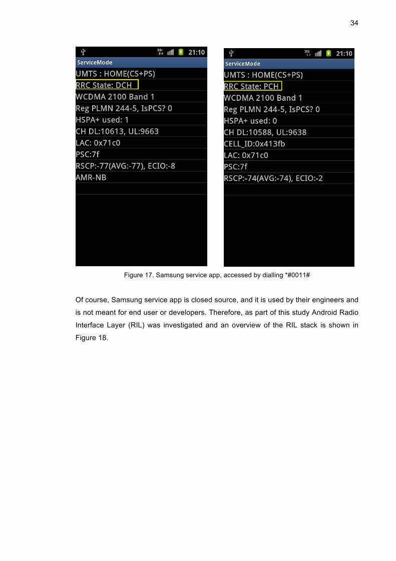
34
Figure 17. Samsung service app, accessed by dialling *#0011#
Of course, Samsung service app is closed source, and it is used by their engineers and
is not meant for end user or developers. Therefore, as part of this study Android Radio
Interface Layer (RIL) was investigated and an overview of the RIL stack is shown in
Figure 18.

35
Figure 18. RIL stack [14]
Looking at RIL architect (Figure 18), there was a need to choose an intervention point,
or in other words, at what level of the stack should the modification take place. The
baseband definitely offers what is needed and more, but it lives in its own shell, own
CPU and own memory. Hacking into the baseband chipset is difficult mission. Next
comes Linux kernel, which is more realistic option, but still complicated. Going up in the
stack, there are libraries, which are just made of blob of bytes and its always vendor or
manufacturer specific. Application framework on the other hand is relatively easy to
modify, so that was the path chosen. It is worth to mention that having root access in
the mobile device is not enough to tamper with RIL messages, the need was to tamper
with telephony process it self. In order to do that, the Android application being devel-
oped needs to be signed with system keys. Typically all system applications that
comes preloaded with the phone are signed with system keys, such keys are well pro-
tected by their owners. The only option left is to build own custom android OS image as

36
part of this study. Only that way, it is possible to acquire own system keys. Once the
application is a signed system app, it can live together in telephony process, where it is
allowed to communicate RIL messages. Speaking of which, RIL messages are split
into two categories:
• Solicited Commands:
They start with an activity or request generated by the user or the OS. A user can
initiate a call or send SMS, which will result in generating a RIL request. The OS in
the other hand generates RIL requests frequently, for example, to check for signal
strength. Figure 19 is good example of solicited call flow.
Figure 19.Diagram illustrates a solicited call in Android [14]
It is noticeable that the thread executing the Dial() function in (Figure 19) diagram
will return immediately, where the native RIL implementation and the baseband
firmware is taking over. The baseband firmware is working in SoC where it enjoys
its own CPU and memory.Here is a list of most interesting RIL solicited requests:
RIL_REQUEST_GET_SIM_STATUS RIL_REQUEST_ENTER_SIM_PIN
RIL_REQUEST_ENTER_SIM_PUK RIL_REQUEST_CHANGE_SIM_PIN
RIL_REQUEST_DIAL RIL_REQUEST_GET_IMSI

37
RIL_REQUEST_HANGUP RIL_REQUEST_CONFERENCE
RIL_REQUEST_BASEBAND_VERSION RIL_REQUEST_SIGNAL_STRENGTH
RIL_REQUEST_OPERATOR RIL_REQUEST_RADIO_POWER
RIL_REQUEST_DTMF RIL_REQUEST_SEND_SMS
RIL_REQUEST_SET_MUTE RIL_REQUEST_WRITE_SMS_TO_SIM
RIL_REQUEST_OEM_HOOK_RAW RIL_REQUEST_OEM_HOOK_STRINGS
RIL_REQUEST_SEND_USSD RIL_REQUEST_GET_IMEI
RIL_REQUEST_SET_BAND_MODE RIL_REQUEST_VOICE_RADIO_TECH
RIL_REQUEST_DEVICE_IDENTITY RIL_REQUEST_QUERY_TTY_MODE
• Unsolicited Commands:
They start with activity initiated by the network or the baseband. The network can
signal some RRC messages to the mobile device in case of an incoming call, which
will be received firstly by the baseband where it will translate the RRC messages to
RIL unsolicited commands, then they will be pushed forward up in the stack till it
reaches the phone UI. Figure 20 holds an example of unsolicited call flow.
Figure 20. Diagram illustrates an unsolicited call in Android [14]
As seen in Figure 20 the incoming call triggered a series of events that is assum-
ing that the user has accepted the call and the connection got established, other-
wise, there would be different scenario if the call was rejected. In any case,
RIL_UNSOL_CALL_RING will be used to promote the user the option to accept or
reject the call.

38
Here is a list of most interesting RIL solicited requests:
RIL_UNSOL_RESPONSE_NEW_SMS RIL_UNSOL_ON_USSD
RIL_UNSOL_SIGNAL_STRENGTH RIL_UNSOL_RINGBACK_TONE
RIL_UNSOL_OEM_HOOK_RAW RIL_UNSOL_CELL_INFO_LIST
RIL_UNSOL_RIL_CONNECTED RIL_UNSOL_STK_SESSION_END
RIL_UNSOL_SIM_REFRESH RIL_UNSOL_CALL_RING
RIL_UNSOL_SIM_SMS_STORAGE_FULL RIL_UNSOL_ON_USSD_REQUEST
RIL_UNSOL_CDMA_INFO_REC RIL_UNSOL_CDMA_CALL_WAITING
RIL_UNSOL_STK_EVENT_NOTIFY RIL_UNSOL_STK_CALL_SETUP
Out of many RIL commands, it was discovered that Samsung service mode is using
(RIL_UNSOL_OEM_HOOK_RAW) and (RIL_REQUEST_OEM_HOOK_RAW). The
commands used were pin pointed by running the service mode app on RF monitor ac-
tivity and then watch output of Logcat for radio, which can be accessed by the following
command:
adb logcat -‐b radio
It is worth to note that radio log is not part of the main default logcat and cannot be ac-
cessed by simply applying filtering, since radio logging has its own buffers.
3.6.1 RRC State Broadcasting Service
The goal was to develop an Android service that can broadcast the RRC state in real-
time where any app installed on the device can listen and make use of the information.
This service must work as system app and live in the telephony process, that is why
the code was placed for the service app next to other system applications sources, so
the service application will get compiled and signed by the system.
The service code must replicate the way of communicating that Samsung service app
is doing, so decompiling (SamsungServiceMode.apk) was necessary. It was not big
surprise to find that they have heavy obfuscation, however, some useful code and val-
ues were recovered. Of course, those binary values were not human readable, but the
aim was to replicate the communication regardless of what that actually is. It was found
that some custom rom developers have been trying to put open source version of

39
Samsung service mode. The only useful file that was found in their source code reposi-
tory, contained the following methods:
public static byte[] getEndServiceModeData(int modeType) { try { ByteArrayOutputStream baos = new ByteArrayOutputStream(); DataOutputStream dos = new DataOutputStream(baos); dos.writeByte(OEM_SERVM_FUNCTAG); dos.writeByte(OEM_SM_END_MODE_MESSAGE); dos.writeShort(5); dos.writeByte(modeType); return baos.toByteArray(); } catch (IOException e) { Log.e(TAG, "", e); } return null; } public static byte[] getPressKeyData(int keycode, int query) { try { ByteArrayOutputStream baos = new ByteArrayOutputStream(); DataOutputStream dos = new DataOutputStream(baos); dos.writeByte(OEM_SERVM_FUNCTAG); dos.writeByte(OEM_SM_PROCESS_KEY_MESSAGE); dos.writeShort(6); dos.writeByte(keycode); dos.writeByte(query); return baos.toByteArray(); } catch (IOException e) { Log.e(TAG, "", e); } return null; }
Code snippet to compose byte array. [16]
The next step was to write the code, which reads RRC value and broadcast it. High-
lights of the code is provided, so anyone with minimum experience could develop such
functionality.
At first, when developing an app that talks to the baseband, that code should be run in
the same process as (phone), needless to mention, using Java reflection can’t be use-
ful in this case, since the (com.android.internal.telephony.Phone) object is in its own
process. These XML flags in will force the service to run in the (phone) process:
<manifest android:sharedUserId="android.uid.phone" > <application> <service android:name=".RRCService" android:exported="true"

40
android:process="com.android.phone" /> </application>
</manifest>
Thereafter, issuing RIL requests using the (phone) object is possible:
Phone mPhone = PhoneFactory.getDefaultPhone(); private void sendRequest(byte[] data, int id) { Message msg = mHandler.obtainMessage(id); mPhone.invokeOemRilRequestRaw(data, msg); }
Where data comes from (OemCommands.java) mentioned above. Once the answer
arrives – in range of milliseconds – the strings are parsed to extract the RRC state,
then only if the state changes from once state to another, for example, from FACH to
DCH, then an Android intent is broadcasted announcing the new RRC state.
3.6.2 Congestion Recognition Mobile Application
Since the problem of getting RRC state in real-time is solved as explained in the last
paragraph, it is now possible to turn the algorithm into code. The only practical addition
that was made is to generate HTTP requests as soon as the radio goes idle. This
helped to accelerate sample collection; in addition, the content of each request is hold-
ing information about the previous sample. Web application was also developed to pro-
vide real-time monitoring by processing the content of the HTTP requests, more about
that in Real-time monitoring web application subsection.
The application implementation has an Android Service that sends HTTP requests as
soon as the radio goes down. Of course that is an operator network nightmare since it
is the most signalling resources consuming way and it can be considered a form of
denial-of-service (DoS) if it was installed in a big number of mobile phones. However,
this application is not published and the experiments using one mobile device will not
have any noticeable effect.
The second component in the app is UI or activity where collecting samples can be
seen in action (Figure 21).

41
Figure 21. Android application interface
The first row has the four RRC states and it will highlight the corresponding RRC state
according to broadcasts received by the previously developed ‘ RRC state broadcast
service’. The second row shows the status of uplink, downlink, UMTS and HSPA,
where such information is derived from Android’s API Telephony Manager.
There is clear correlation between the state reported by Android OS and the actual
RRC state, it was found that when the OS report UMTS state and there is no downlink
or uplink traffic that means RRC state is RRC_IDLE or PCH, while a UMTS state with
some traffic means that RRC state must be FACH. The following table has the com-
plete state mapping:
UMTS HSxPA
On-going traffic FACH RRC_DCH
No traffic RRC_IDLE/ PCH/ URA_PCH RRC_IDLE
The mapping can help any Android application to make a very accurate guess about
RRC state on any Android ROM, without the need for root access or building own sys-
tem image. This might help a lot of Android developers that are looking for a way to get

42
RRC state. The only drawback is that the mapping cannot tell if it is RRC_IDLE or
PCH.
The congestion label in the middle will turn on once a final congestion case has been
detected; following the CRA logic and decision flow as shown earlier.
Another modification was needed in order to insure that sample collection and meas-
urements are as accurate as they can be. That modification took place in filtering table
to drop any packet that does not belong to the Android app. The following iptables
commands achieved the goal:
iptables -‐A OUTPUT -‐m owner -‐-‐uid-‐owner
"+android.os.Process.myUid()+" -‐j ACCEPT // accepts all traffic
originating from own application
iptables -‐A OUTPUT -‐j DROP -‐-‐dport 1:65500 //blocks all other traf-‐
fic
3.7 Real-time Monitoring Web Application
As part of this study, there was a need to develop a web application meant to show the
congestion recognition algorithm internals in real time, as the Android congestion
recognition mobile application is taking samples and posting them to the web applica-
tion every few seconds. The web application can handle input from many mobile devic-
es. The interface gives a list view of all operators and IMEI of mobile devices under that
operator. It is then as easy as dragging that IMEI under specific operator and dropping
it in the designated area, where a graph will appear showing latest samples values as
they arrive from mobile application. The following graph (Figure 22) is a snapshot of the
web interface.

43
Figure 22. real-time monitoring of running Android CRA instance on Elisa
The graph and the list of devices updates in real-time without need to refresh the page,
once a new CRA instance is installed and started communicating with the server, the
list on the left will list the new device IMEI under the respective operator. After dragging
and dropping one of the devices in the upper designated box, the graph will star draw-
ing the latest twenty samples. According to the algorithm logic, the detection gets acti-
vated only after studying the base line, in order for the logic to know what is normal
connection establishment time and what is abnormal. The normal range is simply the
standard deviation boarders and any value that belong out of the range, it will be
moved to the potential congestion cases stack, where the logic will try to make sense
out of the situation if such abnormal values kept coming. Those spikes will be forgotten
as the potential cases stack gets dropped if the baseline stack got full of normal and
within the baseline range.
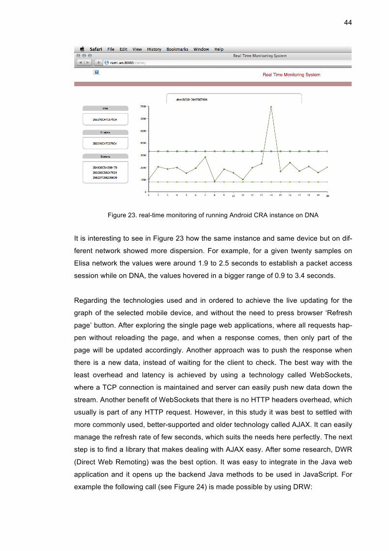
Another snapshot of the web interface (Figure 23) showing data points being collected
while device is connected to DNA network.
44
Figure 23. real-time monitoring of running Android CRA instance on DNA
It is interesting to see in Figure 23 how the same instance and same device but on dif-
ferent network showed more dispersion. For example, for a given twenty samples on
Elisa network the values were around 1.9 to 2.5 seconds to establish a packet access
session while on DNA, the values hovered in a bigger range of 0.9 to 3.4 seconds.
Regarding the technologies used and in ordered to achieve the live updating for the
graph of the selected mobile device, and without the need to press browser ‘Refresh
page’ button. After exploring the single page web applications, where all requests hap-
pen without reloading the page, and when a response comes, then only part of the
page will be updated accordingly. Another approach was to push the response when
there is a new data, instead of waiting for the client to check. The best way with the
least overhead and latency is achieved by using a technology called WebSockets,
where a TCP connection is maintained and server can easily push new data down the
stream. Another benefit of WebSockets that there is no HTTP headers overhead, which
usually is part of any HTTP request. However, in this study it was best to settled with
more commonly used, better-supported and older technology called AJAX. It can easily
manage the refresh rate of few seconds, which suits the needs here perfectly. The next
step is to find a library that makes dealing with AJAX easy. After some research, DWR
(Direct Web Remoting) was the best option. It was easy to integrate in the Java web
application and it opens up the backend Java methods to be used in JavaScript. For
example the following call (see Figure 24) is made possible by using DRW:
45
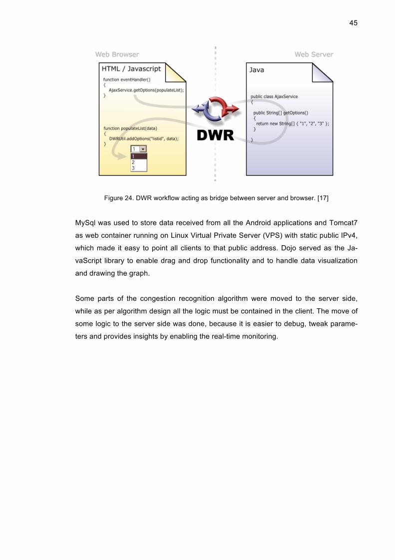
Figure 24. DWR workflow acting as bridge between server and browser. [17]
MySql was used to store data received from all the Android applications and Tomcat7
as web container running on Linux Virtual Private Server (VPS) with static public IPv4,
which made it easy to point all clients to that public address. Dojo served as the Ja-
vaScript library to enable drag and drop functionality and to handle data visualization
and drawing the graph.
Some parts of the congestion recognition algorithm were moved to the server side,
while as per algorithm design all the logic must be contained in the client. The move of
some logic to the server side was done, because it is easier to debug, tweak parame-
ters and provides insights by enabling the real-time monitoring.

46
4 Results and Analysis
Android implementation was used together with the real-time monitoring to test conges-
tion detection, in addition to collecting and analysing samples. In order to validate that
the congestion detection algorithm is able to serve its purpose. The idea is to place it
under controlled congestion where it is possible to turn on/off the congestion and see
how the implementation reacts to it. However, it is hard for any individual to get a live
network to the congestion level in a controlled manner, so the resort was in using net-
work simulators.
4.1 Anritsu Mobile Network Simulator
The machine seen in Figure 25 only needed power and internet access and it was
ready to operate. A SIM card was provided, then it was placed it in the Android mobile
phone that is running the implementation for congestion detection. The machine can
simulate RAN and CN, so the whole stack was there. The mobile phone was able to
obtain packet access and the application was able to connect to own server. Every-
thing was working in order, as the samples were collected and seen in the web inter-
face.
Figure 25. Signalling Tester (Base Station Simulator) MD8475A [18]
While it was relatively easy to get things working, the challenge was to simulate con-
gestion. The first step was to find the process that takes the role of RNC and after that

47
another process was ran with heavy load on the same CPU. An environment similar to
real congestion was created while the heavy load fake process was competing on CPU
resources. It is worth mentioning that starving the RNC process will simulate RNC level
congestion, while congestion can be also on cell level, which is more difficult to repro-
duce. The congestion detection Android application is supposed to be able to detect
RNC and cell level congestion.
At first, the application started to collect samples and study the network. The detection
logic got activated after collecting twenty samples, it was enough to build a baseline of
what is normal setup time for that hardware. After that, The starvation of RNC process
was started by launching the heavy load fake process, and the good news is that in
less than thirty seconds the Android application interface lighted up in red under con-
gestion label, indicating that it was able to detect the congestion, on its own as seen in
Figure 26.
Figure 26. Android CRA implementation was able to detected congestion
Turning off the heavy load process and letting RNC process to function without CPU
starvation, has reflected in the Android application. It changed the state and turned off
congestion notification in less than twenty seconds. The experiment was repeated
many times with consistent results; the Android application was able to detect the con-
gestion period and the non-congestion period.

48
4.2 Finnish Operators (Elisa, Sonera, DNA)
Since the Android phone was running the congestion detection implementation, it was
easy to run it against local mobile operators in Finland by simply placing a SIM card.
The aim was not about detecting congestion but rather to collect samples and study
QoE for their packet access.
In order to achieve similar environment for taking measurement, the same device was
used, same time slot and same location. The location was a residential area in Espoo
city, while the time slot was pick to be at afternoon on Saturdays, since it is expected
that people will be at home and their mobile phones will be camping on same cells as
the Android phone that is doing the measurements. Around 180 samples were collect-
ed within an hour and were stored in the database. The values of the samples (packet
access establishment time) are plotted in the following chart (Figure 27).
Figure 27. Samples of three Finnish operators
DNA seems to have the best results, as most of the values are around two seconds.
On the other hand Elisa and Sonera seem to have more deviation from the mean. Dif-
ferent hardware setup that is used by different operators could explain a part of the
results, in addition to the number of mobile devices being served. Congestion detection
algorithm already overcomes those differences by allowing a learning period before it
gets self activated. The learning period is simply taking samples and building an under-
standing of what is to be considered as normal values for this operator. Of course, the

49
algorithm will update its learning gradually with time. In other words, one instance of
congestion detection got used to the values of four seconds under Sonera network,
then another might find the values alarming and worth firing a PCC (Potential Conges-
tion Case) because it was used to two seconds values on DNA network.
Repeating the tests and measurements under same conditions for the three operators
showed similar distribution curves, adding more reliability to results. However, there are
many factors which can effect the results, and the results were taken under specific
location, which means that the results does not reflect an overall image of an operator
performance in serving packet access.

50
5 Conclusion and Recommendations
The number of mobile applications installed on smart phones is increasing rapidly, and
the vast majority of them require internet connectivity. The infrastructure of mobile
operators is built under the assumption that resources can be shared among subscrib-
ers, since it is less likely for every single subscriber’s device to have the radio up at the
same time. However, nowadays many mobile applications are indeed bringing the ra-
dio up more than expected and without direct request from the user. Typically, the
reason is to check for new content or to send keep-alive messages to keep their con-
nection with their content provider open. The benefit of keeping the connection open is
that the server is able to push new content as soon as it arrives. The biggest offenders
and users of this method are instant messaging applications.
All the players in the telecommunication domain have responded in different ways to
the challenge. For example, network infrastructure manufacturers are calling for more
hardware and more use of smaller cells to meet the demand, while smart phones op-
erating systems trying to help and guide application developers towards more radio
friendly network access.
This study joins those efforts by showing that it is possible to educate mobile devices
about the condition of mobile packet access, which is greatly beneficial for end users,
application developers and mobile operators alike. The algorithm is meant to be run-
ning independently on the mobile device and focuses mainly on measuring radio ses-
sion setup time, which is the time it takes the radio to move from idle state to high
state to transmit some data packets. Of course, not every abnormal value is a red
alarm that is why most of the algorithm logic is about trying to eliminate false posi-
tives. Furthermore, there is a last stage filtering on the server side where all the re-
ports from each instance are collected there. Those reports have information about
quality of service, congestion situation and also explain why the logic concluded that
there is congestion. The collective knowledge of the individually isolated and inde-
pendent logic instance is very valuable when they are plotted on a map, so even if one
of the logic instances in one of the mobile devices mistakenly trigged a final congestion
decision that would be ignored, but if many instances agrees and reported congestion,
then that can be taken seriously.
An Android implementation and a web application worked together to collect the re-
ports and show the logic internals in real-time. They also were used to verify that the

51
algorithm is able to detect congestion, in addition to a network simulator machine.
Using the network simulator it was possible to have a controlled congestion environ-
ment by increasing CPU load on RNC process. The Android application was able to de-
tect whenever there was increased load on the RNC. The implementation was also
used against three operators in Finland. The results showed that CRA was able to
adapt to different hardware and values.
The congestion recognition algorithm is generic and can be integrated at many levels
of the radio stack of a mobile device. The candidates are baseband firmware, vendor
native space or the operating system. The proposal here is to go even further and ad-
vertise the algorithm output for application developers as part of the development API
offered by the operating system. Currently, the APIs that is offered by iOS and An-
droid, which relates to mobile network, are very poor and limited. Application develop-
ers are trying all kind of tricks such as pinging some server to know if there is actually
good connectivity. Broadcasting the algorithm output to mobile applications would
make application developers’ life easier and enable them to have better interaction
with their users, e.g. as displaying the right message according to connectivity status.
There are a lot of use cases where independent real-time congestion detection can
prove useful for the application vendors, network operator and end user. What follows
are some ideas and examples to place the useful output of this study in the big picture
that is the telecommunication field.
5.1 CRA for Mobile Network Operators
Many network measurement tools are available to network operators and they are
monitoring it around the clock. However, they all present only one side of the story.
CRA reports can provide the other side of the story, showing the packet call quality and
establishment latency per cell-id, and that is on top of the congestion analysis and
alerts.
Typically, a subscriber can be experiencing bad connectivity under specific areas and
the operator has no idea what is happening until the subscriber calls customer service
and reports the issue. Customer service can only check from a list of areas under
maintenance and can easily deny the subscriber’s claims since that location is not re-
ported to be having problems according to the operator’s measurements. If complains

52
keeps coming and more subscribers are frustrated, the operator will send a diagnoses
team in a special vehicle loaded with expensive equipment to measure the quality of
experience. Now that can be partly avoided if the operator was getting a report contain-
ing the common knowledge of many CRA instances working independently and report-
ing their observation and decisions. This would serve as a great source of actual QoE
that subscribers are experiencing.
5.2 CRA for Mobile Application Developers
Most of mobile application developers would like to know about current connectivity
situation where they would apply different strategies. For example, a mobile TV appli-
cation would drop down the stream quality even before it starts. Another example is for
an application that offers small Internet packages to be bought by the subscriber, the
application would be able to change some pricing on the fly. For example, offering a
cheaper price if the user accepts that the internet will get activated after the congestion
is gone.
Another example is for traffic optimization applications, where the congestion indicator
provides obviously very useful input, as they can change the optimization level to be
tighter or even block traffic completely when congestion is detected.
5.3 CRA for Mobile Operating Systems
Operating system has the best access to monitor and study the traffic. However, it is
currently not taking full advantage of this privilege. Mobile OS can have congestion
recognition algorithm to provide applications and the user a view over the quality of
service and when there is congestion. This will help applications and users greatly,
whereas applications can follow different techniques according to the latency being
experienced by the user until a radio session is established. The same goes for the
user where the operating system can show a notification to the user in case of in-
creased latency and waiting time for establishing radio session.
Recently, mobile operating systems have put a lot focus on battery life measurements
and calculations where it can show which application is consuming battery inefficiently.
This study propose spending similar efforts to implement the algorithm explained in this
study to show to users their QoE under different geographical locations with their re-

53
spective operators. This allows users to compare between operators and pick the one
which offers the best QoE in their preferred locations or overall. This can go a step fur-
ther, if there was a collective data bases to show the result of all congestion recognition
reports per operator per location, this will be an eye opener for the end users and mo-
bile developers, where they can see real data from mobile devices like theirs and they
don not have to trust operator advertisements. There is something similar for connec-
tion speed network latency, but the radio part of the equation is totally ignored.

References
1 Frédéric Firmin. The Evolved Packet Core. Online source. <http://www.3gpp.org/technologies/keywords-acronyms/100-the-evolved-packet-core>. Cited 1.3.2014.
2 Magdalena Nohrborg. LTE Overview. Online source. <http://www.3gpp.org/technologies/keywords-acronyms/98-lte >. Cited 10.4.2014.
3 Wikimedia.org. File: UDP_encapsulation.svg. Online source. Cited 10.4.2014.
4 Theverge.com. Apple announces 1 million apps in the App Store. Online source. <http://www.theverge.com/2013/10/22/4866302/apple-announces-1-million-apps-in-the-app-store>. Cited 20.4.2014.
5 Senzafili Consulting. The taming of the app. Measuring the financial impact of mobile signalling optimization. White paper. <http://www.senzafiliconsulting.com/Resources/WhitePapers.aspx>. Cited 22.4.2014.
6 Harri Holma ed. Antti Toskala ed. WCDMA for UMTS. Third edition. England: John Wiley & Sons Ltd; 2004.
7 Sharetechnote.com. Handbook_UMTS. Online source. <http://www.sharetechnote.com/html/Handbook_UMTS_Index.html>. Cited 29.4.2014.
8 3GPP, “Radio Resource Control (RRC) protocol specification” 3GPP specification of release 6 – TS 25.331, v6.2.0, Dec. 2008.
9 Artizanetworks.com. RRC Connection Establishment/Release Procedure. Online source. <http://www.artizanetworks.com/lte_tut_cpl_pro.html>. Cited 2.5.2014.
10 Wikia.com. System information blocks. Online source. <http://utran.wikia.com/wiki/System_Information_Blocks>. Cited 3.6.2014.
11 Android.com. NetworkInfo reference. Online source. <http://developer.android.com/reference/android/net/NetworkInfo.html>. Cited 6.7.2014.
12 Android.com. ConnectivityManager reference. Online source. <http://developer.android.com/reference/android/net/ConnectivityManager.html#isDefaultNetworkActive()>. Cited 3.8.2014.
13 At&t. Characterizing Radio Resource Allocation for 3G Networks. Research pa-per. <http://conferences.sigcomm.org/imc/2010/papers/p137.pdf>. Cited 8.10.2014.

14 Netmite.com. RIL stack. Online source. <http://www.netmite.com/android/mydroid/development/pdk/docs/telephony.html> Cited 8.9.2014.
15 Rami Alisawi. Mobile device equipped with mobile network congestion recogni-tion to make intelligent decisions regarding connecting to an operator network. Patent US8750123. <https://www.google.com/patents/US8750123> Cited 7.6.2014.
16 Github.com. OemCommands. Online source. <https://github.com/illarionov/SamsungRilMulticlient/blob/master/app/src/main/java/com/cyanogenmod/samsungservicemode/OemCommands.java>. Cited 5.8.2014.
17 Directwebremoting.org. DWR introduction. Online source. <http://directwebremoting.org/dwr/introduction/index.html >. Cited 5.7.2014.
18 Anritsu.com. MD8475A Signalling Tester. Online source. <http://www.anritsu.com/en-US/Products-Solutions/Products/MD8475A.aspx>. Cited 19.8.2014

