coning in dual completed systems - university of stavangers-skj/coning/740.paterson.pdf · coning...
TRANSCRIPT
Ž .Journal of Petroleum Science and Engineering 23 1999 27–39
Coning in dual completed systems
James Gunning a,), Lincoln Paterson a,1, Boris Poliak b,2
a CSIRO DiÕision of Petroleum Resources, Syndal, Victoria, Australiab Department of Mathematics, UniÕersity of Melbourne, ParkÕille, Victoria, Australia
Received 19 August 1997; accepted 21 January 1999
Abstract
The effectiveness of dual completions at mitigating water coning in thin oil-column reserves is examined in several ways.An analytical model valid for gravity-dominated dynamics is given, and yields useful approximate design formulae. Somerepresentative exact numerical calculations are also presented, showing zones of ‘safe’ operation where pure oil is producedfrom the upper completion, and clean water from the lower. In symmetric designs, water-free production of oil is possible at
Ž .rates many times those available in single-completion systems a factor of 5 or so is possible . Less dramatic improvementsoccur in asymmetric arrangements; perhaps only a factor of 2 is achievable in such designs. The effect of flat-beddedheterogeneity on critical coning rates is investigated numerically, and reveals that coning is critically controlled by thenear-well layers. In particular, highly permeable layers at the completion or in between the completion and the oil–waterinterface assist greatly in reducing coning. q 1999 Elsevier Science B.V. All rights reserved.
Keywords: Coning; Dual completion; Heterogeneity; Thin oil column
1. Introduction
The use of alternative completion techniques tosuppress or mitigate coning in thin oil reserves hasbeen a topic of considerable interest in recent years.Thin oil columns are quite common in Australia,North America, the North Sea, Malaysia, and WestAfrica, and an increasing fraction of remaining re-serves in developed fields will fall into this categorylate in their production period. Oil companies willincreasingly be seeking ways to extract such reserves
) Corresponding author. Fax: q61-3-9259-6900; E-mail:[email protected]
1 E-mail: [email protected] E-mail: [email protected]
more economically than is currently feasible. For thisreason, there is currently extensive investment inalternative drilling and completion techniques, suchas horizontal wells, multilaterals, and multiple com-pletions. The virtual certainty of coning presents aserious economic obstacle to development ofmarginal thin reserves, since much larger equipmentis needed not only to pump the high water–oil ratio
Ž .mixtures, but significant up-front and ongoing costsare incurred for water–oil separation plant at thesurface, and the tight well spacing usually requiredto yield adequate ultimate recovery. In addition, theoverall production is often seriously reduced by thehigh water cut, and overall recovery is reduced.
The most popular technique for developing thinoil reserves at present appears to be horizontal wells,
0920-4105r99r$ - see front matter q 1999 Elsevier Science B.V. All rights reserved.Ž .PII: S0920-4105 99 00006-6
( )J. Gunning et al.rJournal of Petroleum Science and Engineering 23 1999 27–3928
but more detailed examination of the economics ofthese wells sometimes reveals less convincing rea-
Žsons for their use Chugbo et al., 1989; Irrgang,.1994 . Among several difficulties encountered in
Ž .their use have been: 1 vulnerability to poor cement-Ž . Ž .ing, 2 limited recompletion potential, 3 sensitivity
Ž .to natural fractures, 4 design constraints imposedŽ .by drilling technology, and 5 uncertainty as to
whether coning can be restrained when producing atcommercial rates. Part of the difficulty is that themechanisms that cause coning are not directly sub-verted by the use of such wells: they simply takeadvantage of the long perforated interval and reducethe ratio of pressure drawdown to gravitational set-tling forces.
By contrast, multiple completions have been pro-posed to directly address the coning problem, and theprincipal idea is to use the dynamic forces created bythe multiple drawdowns to stabilise the interfacessuch that they do not migrate towards a perforatedzone. Dual completions have been successfully im-
Žplemented in some American fields Wojtanowicz et.al., 1991; Swisher and Wojtanowicz, 1995 and have
proved that water-free oil production is possible atproduction rates very much larger than those possi-ble with only single completions. Clean productionof both water and oil have been demonstrated at highproduction rates, thus eliminating the need for sepa-ration plant. Nontrivial upfront costs are certainlyincurred by the use of these completions, but suc-cessful operation will enable much higher and longerterm production rates than are feasible with singlecompletions.
Nonetheless, there remain several aspects of mul-tiple completion design which have not been ade-quately addressed in previous work. One is the needto furnish a basic theory and some simple empiricalrules upon which to base designs. Theoretical treat-
Žments in the literature to date Wojtanowicz et al.,.1994 appear somewhat ad hoc, so there exists a
need for rigorous solution of a basic model. Anotherproblem is the need to assess the vulnerability ofsuch schemes to weaknesses in field delineation,particularly the issue of reservoir heterogeneity,which usually controls interfacial movement. Exist-ing schemes tend to be pushed to the limits of theirstability, and heterogeneity is certain to amplify un-certainties about the location of unstable regimes.
We investigate in this paper a number of aspectsof a simple multiple-completion design related tothese points. At the most fundamental level, rigorouscalculations for the basic fluid dynamics do notappear to be available in the literature, despite theattention simple coning has received over the years.Some of this work is reviewed in Section 2. Theessential model we use is developed in Section 3,and in Section 4 we present two solutions for theproposed model, one approximate and analytic, theother numerical and exact. The effect of imperme-able barriers above and below the reservoir is exam-ined in Section 5. Finally, the important issue ofheterogeneity and its influence on coning is dis-cussed in Section 6. Here we attempt to quantify theuncertainties in critical coning rates introduced byheterogeneities.
2. Applicability of existing coning calculations
The problem of coning of all types of singlecompletions has received much attention in previouswork, but most treatments are fairly approximate. Abrief survey of the most relevant work follows.
ŽMuskat’s original solution Muskat, 1949; Muskat.and Wyckoff, 1935 neglected the effect of the rising
cone on the potential, and consequently producescritical values around 30% too high. The same ap-proximation is made in the studies of Chaney et al.Ž .1956 and the potentiometric models of Chierici and
Ž . ŽCiucci 1964 . Meyer and Garder’s solutions Meyer.and Garder, 1954; Mian, 1992 are based on the
assumption that a stagnant water cone is in contactwith the bottom of the oil perforations, an assump-tion which is altogether unlikely and probably mis-leading. As has been shown by Blake and KuceraŽ .1988 , the water cone is unstable long before itreaches the well, so such an assumption is unwar-ranted.
Like Muskat’s solution, the analytic approxima-Ž .tion of Høyland et al. 1989 also neglects the effect
of the cone on the potential function and conse-quently overestimates the critical coning rate. Theyalso show that the critical rate is not sensitive to theexact nature of the well-bore boundary conditions,but only to the overall flux Q. By a moderatelyexhaustive numerical study, they produce an empiri-
( )J. Gunning et al.rJournal of Petroleum Science and Engineering 23 1999 27–39 29
cal formula for the critical rate for the isotropicreservoir. Their numerical results do correlate rea-sonably well with the clever analytic approximations
Ž .of Wheatley 1985 , whose solutions try to incorpo-rate the effect of the cone on the potential. Unfortu-nately, the methods of Wheatley cannot be used inmultiple completions, since the image potentials can-not be constructed.
Some extensive simulation-based correlations areŽ .presented by Yang and Wattenbargar 1991 for
closed boundary reservoirs. Their methods can beused in the case of multiple completions, but noanalytical insights are offered.
A range of formulae for vertical and horizontalŽwells are given by Pietraru et al. Pietraru, 1996,.1997; Pietraru and Cosentino, 1993 . These depend
on the notion of a ‘coning radius’, and the authorsgive certain approximations for this quantity whichappear to work well in practice.
Ž .The calculations of Blake and Kucera 1988 aremost consistent in their formulation and solution.They develop an obvious regular perturbation expan-sion for the cone shape, valid for ‘small’ pumpingrates, and shows how the Muskat solution arises as aself-consistent form of the leading order perturbationresult. They also provide exact numerical solutionsof the problem using boundary integral methods.
Some analytical simplifications for the standardimpermeable-top coning problem seem to have been
Žoverlooked by these workers Wheatley, 1985;.Høyland et al., 1989 : these are discussed in Section
5.1.
3. A simple model for the dual completion prob-lem
We confine ourselves in this paper to an elemen-tary equilibrium model, whose equations approxi-mate the long time behaviour of a so-called infinitereservoir. This model furnishes critical rates whichwill then be conservative estimates of the short-timecritical rates as the cone develops. Dual completionswould be designed for situations where the character-
Ž .istic cone-formation times weeks or months aremuch shorter than the anticipated production lifespanŽ .years .
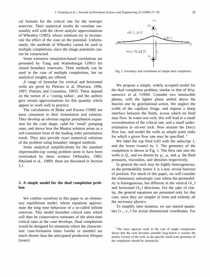
Fig. 1. Geometry and coordinates of simple dual completion.
We propose a simple, widely accepted model forthe dual completion problem, similar to that of Woj-
Ž .tanowicz et al. 1994 . Consider two immisciblephases, with the lighter phase settled above theheavier one by gravitational action. We neglect thewidth of the capillary fringe, and impose a sharpinterface between the fluids, across which no fluidmay flow. In water-wet rock, this will lead to a smalloverestimation of the critical rate, and a small under-estimation in oil-wet rock. Now assume the Darcyflow law, and model the wells as simple point sinksfor which a given flow rate may be specified. 3
Ž .We label the top fluid oil with the subscript 1,Ž .and the lower water by 2. The geometry of the
completion is shown in Fig. 1. The flow rate into thewells is Q , and we denote by p , m and r the fluidi i i i
pressures, viscosities, and densities respectively.In general the rock may be highly heterogeneous,
so the permeability tensor k is a non–trivial functionof position. For much of this paper, we will considerthe elementary anisotropic case where the permeabil-
Ž .ity is homogeneous, but different in the vertical k vŽ .and horizontal k directions. For the sake of clar-h
ity, the general equations are presented only for thiscase, since they are simpler in form and embody allthe necessary physics.
To simplify later notation, we use starred quanti-Ž .ties r , z for actual dimensional coordinates. For
) )
3 The most rigorous work in the case of single completionsshows that the cone becomes unstable long before it reaches thenearby vicinity of the well, so the specific small scale geometry ofthe completion should be immaterial.
( )J. Gunning et al.rJournal of Petroleum Science and Engineering 23 1999 27–3930
the simple anisotropic case, we define the dimension-less coordinates
r k) v
rs 1Ž .(h k1 h
zsz rh , 2Ž .) 1
Ž .with h h the distance between the original oil–1 2Ž .water interface and the centre of the oil water
completion. Define also the dimensionless heads
k h p qr gzŽ .h 1 i i )
f s is1,2, 3Ž .i Q mi i
in terms of which the Darcy flow equations for thefluids in each region are
= 2f sd zy1 d r r2p r 4Ž . Ž . Ž .1
= 2f sd zqh d r r2p r , 5Ž . Ž . Ž .2
Ž .with hsh rh , and d x the Dirac delta function.2 1
Now at the interface of the two fluids, which weŽ .denote by z sh H r , the pressures of the two
) 1
fluids must match, and if we write this down interms of dimensionless heads, we get
H r sq f r , H r yq f r , H r . 6Ž . Ž . Ž . Ž .Ž . Ž .2 2 1 1
Here
Q m1 1q s , 7Ž .1 2k r yr ghŽ .h 2 1 1
Q m2 2q s 8Ž .2 2k r yr ghŽ .h 2 1 1
are dimensionless flow-rates which represent roughlythe ratio of the pressure drawdowns caused by thepumping to the gravitational head tending to restorethe cone to its original position.
Two further boundary conditions are required,which come from imposing no flow across the inter-face, and secondly making the pressures and thecone behave a long way from the wells. The firstcondition amounts to
Ef EH Efi iy s0, 9Ž .ž /Er Er Ez Ž .zsH r
Ž .and the latter simply says that f r, z ™0 andiŽ .H r ™0 far from the wells.
Notice that the model thus far encompasses thesingle-completion case as well, since we need onlyset Q sq s0 and the equations above will reduce2 2
Žto those for a single well above the interface theŽ .flow Eq. 5 decouples totally from the system and
.can be discarded . The problem is then identical toŽ .that of Blake and Kucera 1988 , and their exact
solutions will be useful for comparison. A key resultof their work is that the dimensionless critical rate isq f2.1, from which we easily compute the critical1
Ž .Q from Eq. 7 . It is usual to divide this rate by B ,1 0
the formation volume factor, to get the surface criti-cal rate.
4. Solution methods for the coning problem
4.1. Analytic solution for small flow rates
In Appendix A we use a perturbation scheme toderive an analytic solution of the coning problem
Ž . Ž .summarised by Eqs. 4 – 9 , valid for dimensionless< <flow rates q -1. The leading order solution isi
1 q q1 2Hs y , 10Ž .ž /2 2 2' '2p r q1 r qh
which shows how the q flow pulls the interface up,1
and the q flow draws it down. This formula can be2
used to predict the approximate interface position ifŽ . 2the flow rates satisfy Q -k r yr gh rm . Iti h 2 1 1 i
Žcannot be used to derive a critical rate this is outside.the regime of validity of the perturbation method ,
but rather should be seen as an approximate guide tothe interface shape and an indicator of the role of thedual-completion height ratio h.
Note also that the ‘size’ of the downward-conepart of this formula is dictated by the length ratiohsh rh , so for example if we were tempted to2 1
Ž .make h -h h-1 in order to enhance the2 1
pulling-down effect directly underneath the wellŽmotivated, say, by the desire to pump less water,
.which reduces q , then the cone away from the near2
well-bore region will be determined by the largerlength h . This leads to a ‘Mexican-hat’ cone, which1
could become unstable as the pumping rates areŽincreased. Wojtanowicz and coworkers Wojtano-
( )J. Gunning et al.rJournal of Petroleum Science and Engineering 23 1999 27–39 31
.wicz et al., 1991, 1994 have also noted this possibil-ity in their work.
4.2. Numerical solution using finite-difference meth-ods
To overcome the limitations of the perturbationŽmethod used in the analytical solution i.e., small
.flow rates q -1 , a full numerical solution of thei
problem was developed using a customised finite-difference code. The solutions obtained by this meansare exact, up to the usual discretisation error.
The choice of the finite difference grid was deter-mined by the requirement that the code should copewith arbitrary reservoir heterogeneity, since hetero-geneity is known to have a significant influence onconing. For this reason, we used equispaced cylindri-cal-coordinate grids for the flow calculations, in spiteof their non-optimal efficiency for spherical or cylin-drical flows.
The algorithm used to compute the interface posi-Ž .tion consisted of the following steps: 1 Guess an
initial interface, consisting of a set of grid nodes justŽ .above the ‘true’ interface. 2 Set the permeability on
the links just below the interface nodes to zero,Ž .which imposes no-flow across the interface. 3 Solve
Ž .the flow problem 4,5 on the grid, i.e., compute theŽ .flow for this fixed interface, and then 4 from the
computed pressures calculate a better position for theinterface so as to match the pressures across the
Žinterface more accurately i.e., a kind of root-finding. Ž .exercise at each discretised radius r , and 5 iteratek
these steps until the interface is stable in some senseŽe.g., limiting cycles may be acceptable—this is
.likely in discretised, sharp-interface problems .A simple relaxation method was used to solve the
flow problem, which has certain advantages in itera-tive schemes, since good initial guesses of the poten-tial field are usually available. The algorithm is adirect equivalent to the integral-equation iterative
Ž .method used by Blake and Kucera 1988 and isquite stable providing the initial guess is sensible.
It is easy to see that the far field pressures mustŽ .approach those of a point sink Q Q a distance h1 2 1
Ž . Ž .h above below the plane zs0, so if the size of2
the numerical grid is appreciably larger than theŽ .largest of h , h say 10 times bigger , the solution1 2
can be prescribed on the outer boundary without
affecting the outcome. Similarly, the flow in thevery-near well-bore region is perfectly spherical, sothe pressures can be prescribed on the grid-blocksadjacent of the well with impunity. Since we onlysolve for r)0, no-flow across the boundary rs0 isprescribed for reasons of symmetry. The generalcylindrical form of the finite difference operatorswas used. With the order of several hundred grid-blocks along each direction, and 20–30 separatingthe wells from the interface, the accuracy of thenumerical solutions was estimated to be around 5%or better. For example, we checked the code bysetting Q s0 and hunting for the critical coning2
rate q . This came out to be q f2.1, with grid-de-1 1
pendent fluctuations of only a few percent, in agree-ment with the calculations of Blake and KuceraŽ .1988 .
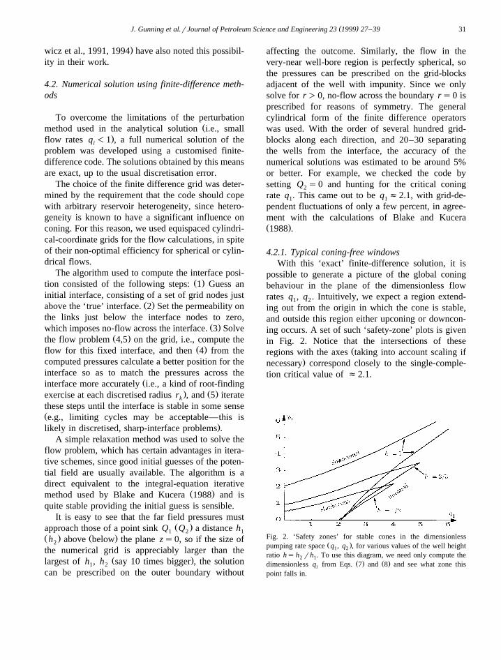
4.2.1. Typical coning-free windowsWith this ‘exact’ finite-difference solution, it is
possible to generate a picture of the global coningbehaviour in the plane of the dimensionless flowrates q , q . Intuitively, we expect a region extend-1 2
ing out from the origin in which the cone is stable,and outside this region either upconing or downcon-ing occurs. A set of such ‘safety-zone’ plots is givenin Fig. 2. Notice that the intersections of these
Žregions with the axes taking into account scaling if.necessary correspond closely to the single-comple-
tion critical value of f2.1.
Fig. 2. ‘Safety zones’ for stable cones in the dimensionlessŽ .pumping rate space q , q , for various values of the well height1 2
ratio hs h rh . To use this diagram, we need only compute the2 1Ž . Ž .dimensionless q from Eqs. 7 and 8 and see what zone thisi
point falls in.

( )J. Gunning et al.rJournal of Petroleum Science and Engineering 23 1999 27–3932
Now in practice, it is usually desirable to pump aslittle water as possible, for a mixture of economic orenvironmental reasons. This amounts to trying toreduce q , while still maintaining the enhanced wa-2
ter-free production that the dual completion gives.One way of doing this is to complete the water wellnearer to the interface position, thus reducing h, andbringing down the safety region indicated in Fig. 2.Reductions of water production by of the order of 20or so are possible by these means, but at the risk ofoperating near the critical boundaries.
5. The effect of impermeable upper and lowerbarriers
In the preceding sections, we implicitly ignoredthe effect of any upper boundaries on the oil region,such as an adjoining gas cap. If there is a gap capclose to the oil well, then gas coning will almostcertainly occur: gas coning is usually a more difficultphenomenon to model realistically than water con-ing, since the large viscosity difference means thatthe gas cone may be a complex fingered structurecontrolled by heterogeneity, not a simple movinginterface. Thus we shall assume that the oil well iseither very far from a gas–oil contact, or that the oilis bounded above by an impermeable barrier. In thecase of dual completions, the proximity of a imper-meable barrier underneath the water zone has astrong influence on the behaviour of a dual comple-tion, as we shall see in Section 5.2.
The main difficulty with introducing barriers isthe number of extra free parameters they introduce.Section 5.1 presents an analytic solution for thesingle-completion case, based on an elegant symme-
Ž .try argument given in Appendix B which reducesthe number of apparent free parameters. Section 5.2presents some representative numerical calculationsfor the dual completion problem.
5.1. Accurate approximate formulae for the single-completion case
The presence of an impermeable barrier above theoil zone is routinely handled by the inclusion ofappropriate boundary conditions. The classic prob-lem of single-completion bottom-water coning is
usually formulated in a similar way to the ‘free-space’problem, but an impermeable horizontal barrier isintroduced at z sh , and the well is modeled as a
) 1
line-like source extending some fraction f of theway into the formation region above the virgin waterlevel. The large r potential in such a constrainedsituation is then logarithmic, and will diverge at
Žinfinity unless some finite cutoff is introduced whatthis means is that a sufficiently large bounded reser-
.voir will always cone after a sufficiently long time .The ad hoc remedy is to impose a boundary condi-tion fs0 at some radius rU which is the reservoire
size.The solution for this problem is developed in
Appendix B, and yields a dimensionless critical rate
1.4Qm B 1.57 1y fŽ . Ž .1 oqs s , 11Ž .2 2k D r gh 1q0.177 log rŽ .h 1 e
where the formation volume factor B is incorpo-0
rated if we want a surface rate Q. Notice that we willalways have r )1 and 0- f-1, so the dimension-e
less critical coning rate is always less than 1.57,which in turn is less than the ‘free-space’ value of2.1. This is reasonable, since coning is expected tobe more severe in a bounded situation than an un-bounded one. This expression was checked using thedirect finite-difference code, and was found to beaccurate within a few percent for all reasonablevalues of r .e
5.2. Numerical solutions for the dual completioncase
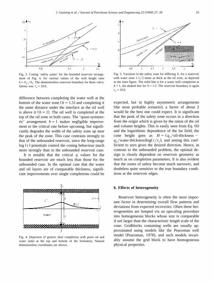
The numerical solution described in Section 4.2 isroutinely adapted for the dual completion case withupper and lower seals, and it is straightforward togenerate exact stability diagrams for whatever con-figuration is required. A typical example for a homo-geneous reservoir is shown in Fig. 3, where we havearbitrarily set the scaled reservoir radius r s10.6,e
and the two wells are completed at the very top andbottom of the oil and water zones respectively, asshown in Fig. 4.
Another interesting case is shown in Fig. 5, wherethe reservoir has a water layer 1-1r2 times as thickas the oil layer, and the two curves shown reveal the
( )J. Gunning et al.rJournal of Petroleum Science and Engineering 23 1999 27–39 33
Fig. 3. Coning ‘safety zones’ for the bounded reservoir arrange-ment of Fig. 4, for various values of the well height ratiohs h rh . The dimensionless reservoir boundary for these calcu-2 1
lations was r s10.6.e
difference between completing the water well at theŽ .bottom of the water zone hs1.5 and completing it
the same distance under the interface as the oil wellŽ .is above it hs1 . The oil well is completed at the
top of the oil zone in both cases. The ‘quasi-symmet-ric’ arrangement hs1 makes negligible improve-ment to the critical rate before upconing, but signifi-cantly degrades the width of the safety zone up nearthe peak of the zone. This case contrasts strongly tothat of the unbounded reservoir, since the long-range
Ž .log r potentials control the coning behaviour muchmore strongly than in the unbounded reservoir case.
It is notable that the critical q values for thebounded reservoir are much less than those for theunbounded case. In the optimal case that the waterand oil layers are of comparable thickness, signifi-cant improvements over single completions could be
Fig. 4. Depiction of generic dual completion with point oil andwater sinks at the top and bottom of the formation. Naturaldimensionless coordinates are shown.
Fig. 5. Variation in the safety zone for differing h, for a reservoirwith water zone 1-1r2 times as thick as the oil zone, as depictedin the inset figure. The solid line is for a water well completion aths1, the dashed line for hs1.5. The reservoir boundary is againr s10.6.e
expected, but in highly asymmetric arrangementsŽ .the most probable scenario , a factor of about 2would be the best one could expect. It is significantthat the peak of the safety zone occurs in a directionfrom the origin which is given by the ratios of the oil
Ž .and column heights. This is easily seen from Eq. 6and the logarithmic dependence of the far field; the
Žcone height goes as H ; q roil-thickness y1. Ž .q rwater-thickness log rrr , and setting this coef-2 e
ficient to zero gives the desired direction. Hence, incontrast to the unbounded problem, the optimal de-sign is clearly dependent on reservoir geometry asmuch as on completion parameters. It is also evidentthat the zones of safety become much narrower, anddoubtless quite sensitive to the true boundary condi-tions at the reservoir edges.
6. Effects of heterogeneity
Reservoir heterogeneity is often the most impor-tant factor in determining overall flow patterns anddeviations from expected recoveries. Often these het-erogeneities are lumped via an upscaling procedureinto homogeneous blocks whose size is comparableif not larger than the characteristic length scale of thecone. Gridblocks containing wells are usually ap-proximated using models like the Peaceman well
Ž .model Peaceman, 1978 , and such models invari-ably assume the grid block to have homogeneousphysical properties.

( )J. Gunning et al.rJournal of Petroleum Science and Engineering 23 1999 27–3934
Two limiting cases of heterogeneity are easy toexplain. In the case of very long scale fluctuations,the coning behaviour is dominated by the local val-ues of the permeability, and insertion of such values
Ž .in the scaling relations 7,8 would give a reliableguide to the critical pumping rates. Such fluctuationswould have to be on the scale of many tens ofmeters. The other limiting case occurs when theformation has much short range disorder, but looksfairly homogenous on the length scale of the comple-tion design. In this case the appropriate values of thepermeabilities would be those found in short-range
Ždisorder studies see e.g., Dagan, 1979; King, 1987,.1989 , which are usually close to the geometric
mean. Neither of these case are likely to occur inpractice, and the reservoir heterogeneity will in allprobability span all length scales available to physi-cal measurement.
One case of heterogeneity which is reasonablyŽamenable to current computational power recalling
that we need at last 200 grid blocks in any given.direction to avoid recourse to some sort of upscaling ,
is the case when the completion is made in a hori-zontally-layered region, such that the local flow hascylindrical symmetry. The problem is then two-dimensional and much faster to solve.
We have performed Monte-Carlo simulations ofthe coning behaviour of the unbounded reservoir inthis scenario, where the layer permeabilities are allo-cated according to some a priori covariance function,as is common in heterogeneity studies. The geostatis-tical model for the rock properties is assumed to bestationary, and we assume a log–normal distributionfor the layer permeabilities ys log k with exponen-tially decaying covariance: 4
2 y < z yz < rlj iy z yy y z yy ss e 12Ž . Ž . Ž .² :Ž .Ž .j i
Here l is a decay length scale, and s measuresthe strength of the heterogeneity. The mean of thelogarithm of the permeability is y. The up-front LUdecomposition of the covariance matrix was themethod used to generate the realisations of the per-
Žmeability field Alabert, 1987; Duetsch and Journel,
4 It turns out that the specific form of the covariance is not ofgreat importance, for reasons which we omit for the sake ofbrevity.
.1992 , and each realisation was normalised to give aconstant geometric mean.
Two approximations have to be made in order toset the boundary conditions. At ‘infinity’, i.e., the
Ž .edge of the r, z region a long way from the wells,the potentials are set to the asymptotic values one
Ž .can derive for a point source above or below a flatŽimpermeable plane in a homogeneous field see Eqs.
Ž . Ž ..15 and 16 . This is a fairly harmless approxima-tion, as the flow will quickly adopt the desiredheterogeneous pattern within a few l of the gridboundary, which can still be far from the wells. Thesecond approximation is that the head values on thegrid points immediately adjacent to the well,Ž . Ž .i , j "1 and i q1, j are set to valueswell well well well
corresponding to spherical flow in a region of per-meability equal to the geometric mean of the threelayers in question. Again, the assumption is that the
Žflow will quickly adopt a nonspherical pattern de-.pending on the heterogeneity within a few l, and
still a long way from the cone crest.For the simulations, we chose to investigate the
single-completion case only, as the qualitative natureof the results will be very similar to those formultiple completions. A 200=200 grid was used,with 25 nodes separating the single well from the flatinterface reference level. Simulations were run for‘short’ and ‘long’ permeability correlation lengths,
Fig. 6. Typical realisations of the layer permeabilities used in thenumerical calculations. The plots are of log K vs. grid index, and
Ž . 2 y < iy j < r5the realisations have correlation function C i, j ss e .Here s s0.6 is the standard deviation of the normal distributionof log K. Successive realisations are displaced by a factor of 3 forvisual convenience.

( )J. Gunning et al.rJournal of Petroleum Science and Engineering 23 1999 27–39 35
Ž . 2 y < iy j < rlFig. 7. Bin counts for the critical q values for the exponential covariance C i, j ss e , with ls5, for standard deviationsss0.3, 0.6, 0.9, 1.2, from left to right. Inset diagrams show more resolution for the narrower distributions. Clearly the uncertainty in thecritical q increases with increasing heterogeneity, and the distribution becomes quite right-skewed. Sample means and standard deviationsfor the critical q’s are given in Table 1.
Žls5 and ls50 respectively, as measured on grid.coordinates . A series of typical realisations with
short correlation length is shown in Fig. 6.For several values of the standard deviation s ,
the critical q value of 150 realisations was computednumerically and the resulting distributions were con-structed. Bin counts of the statistics are shown inFig. 7.
Two trends are evident from this Monte-Carlosimulation. Firstly, the increasing right skewness ofthe distribution means that the average critical con-
ing parameter increase slightly with increasing for-mation heterogeneity. The probability of underesti-mating the critical rate is much higher than theprobability of overestimating it. This is good if theformation is flat bedded as in this case. The secondtrend is that the uncertainty in the critical q increaseslinearly with the uncertainty in the permeability de-
Žscription, but with slope of less than unity see the.last column in Table 1 . This also is favourable; the
uncertainties in the coning behaviour are somewhatless than those in the formation permeability. How-
Table 1Statistics from the Monte Carlo computation of the distribution of the critical coning parameter q
2m ² : ² :(Correlation parameters e ; ms log q s s log qym s rsŽ .q q
Ž . Ž .ls5, ss0.3 2.07 2.02,2.11 0.13 0.12,0.15 0.45Ž . Ž .ls5, ss0.6 2.17 2.08,2.26 0.27 0.24,0.30 0.45Ž . Ž .ls5, ss0.9 2.36 2.22,2.52 0.40 0.36,0.45 0.45Ž . Ž .ls5, ss1.2 2.67 2.45,2.90 0.54 0.48,0.61 0.45Ž . Ž .ls50, ss0.3 2.10 2.04,2.16 0.18 0.16,0.20 0.60Ž . Ž .ls50, ss0.6 2.16 2.04,2.30 0.36 0.33,0.41 0.60Ž . Ž .ls50, ss0.9 2.25 2.06,2.46 0.55 0.49,0.62 0.61Ž . Ž .ls50, ss1.2 2.35 2.09,2.65 0.74 0.66,0.83 0.61
One hundred fifty samples were used and 95% confidence intervals are shown for the statistics in brackets. Standard x 2 tests were used onthe log q data, which assumes this approximates a normal distribution.

( )J. Gunning et al.rJournal of Petroleum Science and Engineering 23 1999 27–3936
Ž .Fig. 8. Dotted curves: correlation coefficient between the ‘three-layer-averaged-permeability’ at height z explained in the text and theŽ .critical q for the permeability realisation, for the short-range correlation case ls5 . The left graph is for ss0.6, and the right for
ss1.2. Clearly, the inference is that higher critical q’s are obtained when the permeability in the near well-bore region is high, even in theŽ .region below the well. A typical realisation with unusually large ‘coning resistance’ q s4.28 is shown dashed on the left graph. SimilarcritŽ .correlation coefficient graphs are obtained for the longer range correlation simulations ls50 , except the peak is more diffuse and extends
further up into the formation, as one would expect. The asymmetry is also less pronounced.
ever, the standard deviations in the critical coningrates are still large, e.g., the range of q values forthe last simulation in Table 1 spanned two decades.Observe also that the uncertainties increase withincreasing correlation length of the realisations,which will be important in formations that have longcorrelation lengths and little hard data.
From the simulation studies it is also possible todetermine the most important regions of the perme-ability realisation with respect to coning. Fig. 8shows plots of the correlation coefficient betweenthe ‘three-layer-averaged-permeability’ at a height zon the grid, and the critical q for that particular
Ž .realisation, for short-range correlations ls5 .The ‘three-layer-averaged-permeability’ is simply
the mean permeability of the three layers centered atheight z on the grid. This averaging process acts as amoving average filter and makes the plots less noisythan those obtained without layer averaging. Valuesof the correlation coefficient below 0.2 are unlikelyto have much statistical significance, so the oscilla-tions in the correlation coefficient above the well arenot significant.
The peaks of the two graphs occur at the welllayers, as it does in all simulations we studied, whichemphasises the need to complete wells in a highpermeability zone. The natural extension of this is to
Žtry to make horizontal fractures usually very diffi-.cult , or put in horizontal wellsrmultilaterals. Inter-
estingly, the asymmetry of the graph about the wellheight also indicates that it is better to completewells at the top of a high permeability region, ratherthan the bottom. The high permeability region acts tospread out the pressure concentration as far as possi-ble, thus reducing the cusping instability associatedwith coning.
7. Conclusions
The perturbation treatment indicates that symmet-rical arrangements are most favourable when thereservoir boundaries are far away, and that very largeimprovements in pumping rates are possible. In re-serves that have strongly confining boundaries, how-ever, the optimal designs are not necessarily sym-
( )J. Gunning et al.rJournal of Petroleum Science and Engineering 23 1999 27–39 37
metric, and the behaviour of the far-field potentials ismore important in optimising design. Less dramaticimprovements are possible in such asymmetric de-signs, but the improvements in critical rates are stillvery significant.
The heterogeneity studies confirm the establishedobservation that completion in highly permeable lay-ers tends to mitigate coning, and shows that particu-larly favourable completions in highly heterogeneousreservoirs may have critical coning rates many timesgreater than that for the equivalent ‘homogenised’reservoir. In flat-bedded cases, highly permeable lay-ers between the oil well and the interface assistgreatly in mitigating coning, which may not be sowell known.
The conclusions here are valid for quite generalwell models, and the numerical methods of thispaper can be routinely extended to other well modelsand different boundary conditions on the reservoir
8. Nomenclature
Symbol Remarks ReferenceB formation0
volumefactor
m , m viscosities1 2Ž .f dimensionless Eq. 3
headr , r densities1 2
h , h well to interface Fig. 11 2
distancesH h rh2 1
k , k verticalrhorizontalv h
permeabilityp , p pressures1 2
Q , Q actual well-bore1 2
fluxesŽ . Ž .q , q dimensionless Eqs. 7 and 81 2
well-bore fluxesŽ . Ž .r, z dimensionless Eqs. 1 and 2
cylindricalcoordinates
Ž .l, s , y properties Section 6, Eq. 12heterogeneouspermeabilitymodel
Acknowledgements
This research was supported in part by the Mel-bourne University Collaborative Research Pro-gramme
Appendix A. Analytic solution for small flow rates
If the flow rates Q are sufficiently small, then theiŽ . Ždimensionless numbers q in Eq. 6 are small q -i i
.1 , and the solution can then be written as a perturba-tion series in the q . So if we writei
H r sq H Ž1,0. r qq H Ž0,1. r qq2H Ž2,0. rŽ . Ž . Ž . Ž .1 2 1
qq2 H Ž0,2. r qq q H Ž1,1. r q PPPŽ . Ž .2 1 2
13Ž .
f r , z sq f Ž1,0. r , z qq f Ž0,1. r , zŽ . Ž . Ž .i 1 i 2 i
qq2f Ž2,0. r , z qq2f Ž0,2. r , zŽ . Ž .1 i 2 i
qq q f Ž1,1. r , z q . . . 14Ž . Ž .1 2 i
and expand all the differential equations and bound-ary conditions as a double series in q , q , then the1 2
usual hierarchy of equations emerges which may besolved sequentially as far as desired.
The leading order problem turns out to be theŽ . Ž .Poisson Eqs. 4 and 5 for each f, with no flow
across the plane zs0. These may be solved triviallyby the method of images, and give the solutions
1 1 1f sy q1 2 22 2ž /4p ( (zy1 qr zq1 qrŽ . Ž .
15Ž .
1 1 1f sy q .2 2 22 2ž /4p ( (zyh qr zqh qrŽ . Ž .
16Ž .Ž .The interfacial boundary condition 6 at leading
order then gives the interface position as
1 q q1 2Hs y . 17Ž .ž /2 2 2' '2p r q1 r qh
This shows how q ;Q pulls the interface up,1 1
and how q ;Q pulls the interface down. It reduces2 2
to Blake’s result if q s0.2

( )J. Gunning et al.rJournal of Petroleum Science and Engineering 23 1999 27–3938
The higher order terms are tedious to obtain andrequire some effort to compute. We omit them herefor the sake of brevity. The effects of the cone on thepotential only start to appear in these higher orderterms. Hence the perturbation treatment is a convinc-ing way to demonstrate that the Muskat assumptionto neglect the effect of the cone on the potential isvalid only to leading order.
Appendix B. Single-completion case with upperboundary—theory
If we use the same dimensional coordinates as inSection 3, omitting the water-zone completion, theproblem described in Section 5.1 now has two extra
Ž .free parameters, viz. f and r ' r rh k rk . So(e ) e 1 v h
the critical q ought to be a function only of f and r ,e
and thus the real critical coning rate Q ought to scaleas
k D r gh2h 1
Q; G f ,r , 18Ž . Ž .em1
where G is some as yet undetermined function. It isodd that some authors propose scalings different to
Ž .these Høyland et al., 1989; Schols, 1972 , since theyare a unique possibility.
Most authors propose the f dependence to be ofthe form 1y f 2, which is not quite correct, 5 andseek a log r type form for the r dependence. It ise e
possible to derive an exact form of the r depen-e
dence using symmetry arguments which are too longto give in full here. We sketch the line of argumentfor the case fs0.
Consider the problem as sketched in Fig. 9, wherewe imagine that we have found the critical q forc
some r with a point well at the top of the formation.e
For example, using the finite-difference code, weŽhave calculated q f0.80 for r s10.6 which isc e
.very close to Wheatley’s value . Since the equipoten-tial lines at large r are vertical and the far-field
5 Ž .A 1y f dependence does not really make any sense, for2
then EQrE f s0 at f s0, and there is every reason to believe thecritical rate goes down immediately f is increased. Obviously, the
Ž .1.4f factor must vanish at f s1, so the 1y f factor of Yang andŽ .Wattenbargar 1991 looks more sensible.
Fig. 9. Diagram showing coning configuration in dimensionlesscoordinates when there is an impermeable barrier above the oil.
potential is logarithmic, the solution to the problemŽ .we have found with boundary condition f r s0 ise
the same as the problem with boundary conditionŽ X . Ž . Ž X .f r s 1r2p log r rr . It then transpires thate e e
we can stretch the coordinates and offset the poten-tial in such a way as to map the problem exactlyback to its original form, but with a different scalefactor for Q as it appears in the interface pressure–continuity boundary condition. This scale factor tellsus exactly what the new critical rate will be in termsof the old rate q , if the boundary is moved in fromc
r to rX . After a few lines of algebra and using thee e
single value obtained at r s10.6, we get the scalinge
relation
1.57q s , 19Ž .c 21q0.177 log rŽ .e
This unusual log r dependence accounts for thee
fact that various authors have found highly variablefunctional forms for the log r dependence usinge
regression techniques. Numerical simulations showthat this is accurate to within a few percent forr )2, and for r values less than this, the influencee e
of the boundary condition is so great as to justifymore detailed modelling. The overall critical rate, forfs0 is then
k D r gh2 1.57h 1Qs , 20Ž .2m 1q0.177 log rŽ .1 e
An extra factor like Yang and Wattenbargar’sŽ .1.41y f is all that is needed to then give a fullexpression for the standard problem, 6 and the for-
6 The exponent 1.4 is empirically derived: see Yang and Wat-Ž .tenbargar 1991 .

( )J. Gunning et al.rJournal of Petroleum Science and Engineering 23 1999 27–39 39
mation volume factor B can be introduced on the0
denominator if desired to account for release ofdissolved gas. This is the basis of the presented
Ž .formula 11 .
References
Alabert, F., 1987. The practice of fast conditional simulationsthrough the LU decomposition of the covariance matrix. Math.Geol. 19, 369–386.
Blake, J.R., Kucera, A., 1988. Coning in oil reservoirs. Math.Scientist 13, 36–47.
Chaney, P.E. et al., 1956. How to perforate your well to preventwater and gas coning. Oil and Gas Journal 55, 108–114.
Chierici, G.L., Ciucci, M.G., 1964. A systematic study of gas andwater coning by potentiometric models. J. Pet. Technol., 923–929.
Chugbo, A.I., Roux, G.D., Bosio, J.C., 1989. Thin oil columns,most people think horizontal wells, Obagi field case suggests
Žthe contrary. In: 64th annual SPE Technical Conference San.Antonio —Formation Evaluation and Reservoir Geology, pp.
297–306.Dagan, G., 1979. Models of groundwater flow in statistical homo-
geneous porous formations. Water Resources Res. 15, 47.Duetsch, C.V. Journel, A.G., 1992. GSLIB Geostatistical Soft-
ware Library and User’s Guide. Oxford Univ. Press.Høyland, L.A., Papatzacos, P., Skjaeveland, S.M., 1989. Critical
rate for water coning: correlation and analytical solution. SPEReservoir Engineering, 495–502.
Irrgang, H.R., 1994. Evaluation and management of thin oilcolumn reservoirs in Australia. APEA J., 64.
King, P., 1989. The use of renormalization for calculating effec-tive permeability. Transport in Porous Media 4, 37.
King, P.R., 1987. The use of field theoretic methods for the studyof flow in a heterogeneous porous medium. J. Phys. A. 20Ž .19 , 3935.
Meyer, H.I., Garder, A.O., 1954. Mechanics of two immisciblefluids in porous media. J. Appl. Phys. 25, 1400.
Mian, M.A., 1992. Petroleum Engineering Handbook for thePractising Engineer. PennWell Publishing.
Muskat, M., 1949. Physical Principles of Oil Production. Mc-Graw-Hill, New York.
Muskat, M., Wyckoff, R.D., 1935. An approximate theory ofwater coning in oil production. Trans. AIME 114, 144–159.
Peaceman, D.W., 1978. Interpretation of well-block pressure innumerical reservoir simulation. SPEJ, 183–194.
Pietraru, V., 1996. Methode analytique generalisee pour le calcul´ ´ ´ ´Ž .du coning. Revue de l’Institut Francais du Petrole 51 4 .´
Pietraru, V., 1997. New waterrgas-coning solution forŽ .verticalrhorizontal wells. World Oil 218 1 , 55–62.
Pietraru, V., Cosentino, L., 1993. A new analytical approach towater and gas coning for vertical and horizontal wells. Revue
Ž .de l’Institut Francais du Petrole 48 5 .´Schols, R.S., 1972. An empirical formula for the critical oil
Ž .production rate. Erdoel Gas, Z. 88 1 , 1–6.Swisher, M.D., Wojtanowicz, A.K., 1995. New dual completion
method eliminates bottom water coning. Paper number SPE30697, presented at the 1991 SPE Annual Technical Confer-ence and Exhibition, Dallas, Oct. 22–25, 1995, p. 549.
Wheatley, M.J., 1985. An approximate theory of oilrwater con-ing. In: SPE Annual Technical Conference and Exhibition.Paper no. SPE 14210.
Wojtanowicz, A.K., Xu, H., Bassiouni, Z., 1991. Oilwell coningcontrol using dual completion with tailpipe water sink. Papernumber SPE 21654, prepared for the Production OperationsSymposium in Oklahoma City, Oklahoma, April 7–9, 1991,pp. 237–246.
Wojtanowicz, A.K., Xu, H., Bassiouni, Z., 1994. Segregatedproduction method for oil wells with active water coning. J.Pet. Sci. Eng. 11, 21–35.
Yang, W., Wattenbargar, R.A., 1991. Water coning calculationsfor vertical and horizontal wells. Paper SPE 22931 presentedat the 1991 SPE Annual Technical Conference and Exhibition,Dallas, Oct. 6–9.