conjugate forced convection flow past a circular cylinder...
TRANSCRIPT
Conjugate forced convection flowpast a circular cylinder withinternal heat generation
in a porous mediumNur F. Abd Kadir and D.A.S. Rees
Department of Mechanical Engineering, University of Bath, Bath, UK, and
Ioan PopFaculty of Mathematics, University of Cluj, Cluj, Romania
Abstract
Purpose – The aim is to determine the effect of different conductivity ratios on forced convectionpast a circular cylinder embedded in a porous medium, where the solid cylinder forms a uniform heatsource.
Design/methodology/approach – The authors employ an unsteady finite difference method toobtain the resulting steady-state solutions. Interface conditions are applied using the fictitious pointmethod.
Findings – It is found that, the thermal field within the cylinder and in the external porous regiondepend strongly on the ratio of the respective conductivities. In the extreme cases the cylinder actseither as one with a uniform temperature (high-cylinder conductivity) or with a uniform heat flux(low-cylinder conductivity).
Research limitations/implications – Conductivity ratios in the range 0:1 # g # 100 and Pecletnumbers in the range, 1 # Pe # 1; 000 were taken.
Originality/value – Forced convection studies usually focus on cases where the solid phase has aprescribed temperature or heat flux. The present paper employs a uniform heat generation within thecylinder to determine how the therrmal field depends on the Peclet number and the conductivity ratio.
Keywords Heat transfer, Convection, Porous materials, Flow
Paper type Research paper
NomenclatureCp ¼ specific heatf ¼ buffer region functionk ¼ conductivityK ¼ permeabilityp ¼ pressurePe ¼ Peclet numberq00 0 ¼ strength of heat sourcer ¼ radial coordinateR ¼ radius of cylinder
T ¼ dimensional temperatureu ¼ radial velocityU ¼ free stream velocityv ¼ angular velocity
Greek charactersg ¼ conductivity ratioc ¼ streamfunctionr ¼ density
The current issue and full text archive of this journal is available at
www.emeraldinsight.com/0961-5539.htm
One of the authors (IP) wishes to thank the Royal Society for partial financial support. Theauthors would like to thank one of the referees for making them aware of the paper by Kimuraand Yoneya.
HFF18,6
730
Received 13 July 2004Revised 4 October 2007Accepted 4 October 2007
International Journal of NumericalMethods for Heat & Fluid FlowVol. 18 No. 6, 2008pp. 730-744q Emerald Group Publishing Limited0961-5539DOI 10.1108/09615530810885542
m ¼ dynamic viscosityf ¼ angular coordinateu ¼ non-dimensional temperature
Subscripts, superscripts2 ¼ dimensional quantity
c ¼ cylinderi ¼ grid point index in r-directionj ¼ grid point index in f-directionn ¼ timesteppm ¼ porous medium
IntroductionThe importance of heat transfer phenomena associated with free or forced convectionflow in porous media is well known. Interest in this area has been motivated by suchdiverse engineering problems as geothermal energy extraction, storage of nuclearwaste material, ground water flows, pollutant dispersion in aquifers, design of nuclearreactors, solar power collectors, compact heat exchangers, food industries, to name justa few applications. The archival publications of transport phenomena in porous mediahave been reviewed and presented in the recent books by Ingham and Pop (1998, 2002,2005), Nield and Bejan (2005), Vafai (2000, 2005), Pop and Ingham (2001), Bejan andKraus (2003), Ingham et al. (2004) and Bejan et al. (2004).
To date few studies exist of forced convection past a heated cylinder embedded in aporous medium. In a seminal paper Pop and Yan (1998) showed that, it is possible toreduce the high-Peclet number (Pe) forced convection problem to self-similar boundarylayer form, for which analytical solutions are available. An earlier paper by Nasr et al.(1994) looked in detail at how the conductivities and grain sizes of the surroundingporous medium affected heat transfer from a hot cylinder. Kimura (1989) hasconsidered the transient case where the temperature of the cylinder is raised suddenlyfrom the ambient value, and the same author studied an elliptic cylinder using bothintegral and numerical techniques (Kimura, 1988). More recently, Rees et al. (2003) andWong et al. (2004) have considered the effect of utilising the two-temperature model ofconduction in a porous medium, where separate but coupled temperature fieldsassociated with the solid and fluid phases are considered; these papers consider boththe boundary layer limit ðPe!1Þ and moderate values of Pe. At present, there existsonly one paper considering forced convection past a cylinder with a uniform heat fluxfrom its surface. Kimura and Yoneya (1992) conducted an experimental study of thisconfiguration and presented the result of an approximate analytical study of theboundary layer which arises at high-Peclet number boundary. Therefore, at the presenttime, there are are no published studies containing detailed moderate Peclet numbercomputations or a rigorous high-Peclet number boundary layer analysis.
Forced convection flows usually involve heated boundaries with either a prescribedsurface temperature or surface heat flux. A somewhat different situation is consideredhere where uniform internal heat generation within a solid cylinder is the source ofheating for the system and where a uniform external flow exists in the porous mediumoutside of the cylinder. Therefore, this is a type of conjugate heat transfer problem whereneither the local surface temperature nor the heat flux at the surface of the cylinder isknown in advance. These need to be obtained as part of the numerical solutionprocedure by imposing continuity of both temperature and heat flux at the surface of thecylinder, as was done by Kimura and Pop (1992) in a free convection problem. Someaspects of the thermal coupling between a solid medium and a neighbouring saturatedporous medium and a list of references on the topic may be found in the review articlesby Kimura et al. (1997) and Pop and Nakayama (1999), and also in the recent papers by
Internal heatgeneration in aporous medium
731

Vaszi et al. (2003, 2004). Our aim is, therefore, to determine the behaviour of thethermal field surrounding and within a uniformly heat-generating cylinder which isembedded within a fluid-saturated porous medium with a uniform free stream.
Governing equationsThe governing equations for forced convection flow past a circular cylinder of radius Rwhich is embedded in a porous medium are based on the conservation of mass,momentum and thermal energy. We will assume that flow in the porous medium isgoverned by Darcy’s law, and therefore modifications such as form drag(the Forchheimer terms), boundary effects (the Brinkman terms) and anisotropy areeither negligible or absent.
With this in mind the equation of continuity and the momentum (Darcy) equationsmay be written in the forms:
›ru
›�rþ
› �y
›f¼ 0; ð1Þ
�u ¼ 2K
m
›�p
›�r; �y ¼ 2
K
m
1
r
›�p
›f; ð2a; bÞ
where �r and f are the radial and angular coordinates and �u and �y are thecorresponding fluid seepage velocities. The constants, K and m, are the permeability ofthe saturated medium and the dynamic viscosity, respectively. The thermal energyequation for the porous medium may be written in the form:
kpm›2Tpm
›�r 2þ
1
�r
›Tpm
›�rþ
1
�r 2
›2Tpm
›f 2
� �¼ ðrCpÞ �u
›Tpm
›�rþ
�y
�r
›Tpm
›f
� �; ð3Þ
where kpm is the thermal conductivity of the porous medium and Tpm its temperature.The values r and Cp refer to the density and the specific heat. Likewise, the thermalenergy equation for the solid cylinder is:
kc›2Tc
›�r 2þ
1
�r
›Tc
›�rþ
1
�r 2
›2Tc
›f 2
� �þ q000 ¼ 0: ð4Þ
Here, kc is the conductivity of the solid cylinder, q000 is the constant rate of heatproduction within the cylinder and Tc is its temperature.
The cylinder occupies the region �r # R and this provides a natural lengthscale.There is a uniform free stream far from the surface of magnitude U which is in thedirection of increasing �r on f ¼ 0. Therefore, we choose to non-dimensionalise usingthe following transformations:
�r ¼ Rr; ð�u; �y Þ ¼ U ðu; y Þ; �p ¼URm
Kp and T ¼ T1 þ
q000R 2
kcu; ð5Þ
where T1 is the constant temperature of the free stream. As the flow istwo-dimensional it is convenient to introduce the streamfunction, c, according to:
u ¼1
r
›c
›f; y ¼ 2
›c
›r; ð6Þ
HFF18,6
732

and therefore the governing equations (2)-(4), take the non-dimensional form:
›2c
›r 2þ
1
r
›c
›rþ
1
r 2
›2c
›f 2¼ 0; ð7Þ
1
Pe
›2upm
›r 2þ
1
r
›upm
›rþ
1
r 2
›2upm
›f 2
� �¼
1
r
›c
›f
›upm
›r2
›c
›r
›upm
›f
� �; ðr $ 1Þ; ð8Þ
and:
›2uc
›r 2þ
1
r
›uc
›rþ
1
r 2
›2uc
›f 2þ 1 ¼ 0: ðr # 1Þ; ð9Þ
while the dimensionless form of equation (1) is satisfied by equation (6). The Pecletnumber, Pe which appears in equation (8) is defined as:
Pe ¼URðrCpÞ
kpm: ð10Þ
Equation (7) has the solution:
c ¼ r 21
r
� �sinf; ð11Þ
which yields a uniform free stream of unit magnitude when r is large, and which givesc ¼ 0 on both the axis (f ¼ 0, p) and the surface of the cylinder (r ¼ 1).
The boundary conditions for the temperature field are:. that u decays to zero as r increases indefinitely; and. that there is continuity of both temperature and heat flux at the interface between
the cylinder and the porous medium.
Therefore, we require:
uc ¼ upm and kc›uc
›r¼ kpm
›upm
›rat r ¼ 1: ð12Þ
Finally, we define the parameter g, the ratio of the conductivity of the cylinder to thatof the porous medium, as, g ¼ kc/kpm.
Numerical methodEquations (8) and (9) were solved by converting them into time-evolution equationsand time-marching to steady state. Thus, the equations solved were:
›upm
›t¼
1
Pe
›2upm
›r 2þ
1
r
›upm
›rþ
1
r 2
›2upm
›f 2
� �2
1
r
›c
›f
›upm
›r2
›c
›r
›upm
›f
� �; ð13Þ
and:
Internal heatgeneration in aporous medium
733
›uc
›t¼
›2uc
›r 2þ
1
r
›uc
›rþ
1
r 2
›2uc
›f 2þ 1; ð14Þ
where the expressions involving c in equation (13) may be expanded using thedefinition of c in equation (11). Equations (13) and (14) were solved using a finitedifference method on a uniform grid. We define the radial and angular steplengths ashr and hf, respectively, and the number of steps in each of these directions are Nr andNf. Therefore, ri ¼ ihr and fj ¼ jhf; define the spatial grid, and the interface is ati ¼ I, that is, Ihr ¼ 1. The time variable is discretised in the same way with the uniformtimestep ht, and discrete values of t being given by tn ¼ nht. Finally, the numericalapproximation to the exact value of f(rj, uj, tn) is denoted by unij .
The governing equations were discretised using standard second order centraldifferences in space, while timestepping was achieved using the DuFort-Frankelmethod. As the equations are linear, there is no possibility of physical instability, andconvergence to an ultimate steady-state is always obtained when the timestep issufficiently small, otherwise numerical instability arises. On the axis, f ¼ 0, p, centraldifferences in space were employed using the ghost point technique (i.e. settingu ni;21 ¼ u n
i;1) to ensure even symmetry ð›u=›f ¼ 0Þ, thereby reducing thecomputational effort.
At the origin it is not possible to discretise equations (13) and (14) directly sincesome of the coefficients are singular. The Laplacian in equation (14) was thereforeapproximated using the formula:
1
h2r
2
Nf
uc1;0 þ 2XNf21
j¼1
uc1; j þ uc1;Nf2 2Nfuc0;0
" #: ð15Þ
Expression (15) may be derived by recourse to standard five-point Cartesian formulawith steplengths both equal to hr, where all possible ways of writing the five-pointformula (i.e. by rotating the artesian axes so that axes coincide with the grid-lines f¼ constant) are averaged, and then modified according to the fact that ›uc=›f ¼ 0 onthe axis.
At the interface not only is the temperature distribution continuous as r increases,but so is the heat flux, as given by equation (11). A straightforward central differenceapproximation of equation (11) based at the interface will yield an algebraic equationinvolving a upm value at r ¼ rI21 and a uc value at r ¼ rIþ1, both of which may betermed ghost points since they are outside their appropriate domains of existence.However, we may also write down the central difference approximations to bothequations (8) and (9) at the interface. Both the resulting expressions contain the twoghost points, and may be added together in a suitable way so that the application of theapproximation to equation (11) removes the ghost points from the resulting expression.In this way, we obtain a rather lengthy formula which applies at the interface andwhich does not contain ghost points.
Finally, we paid attention to possible numerical difficulties associated with theoutflow boundary, which occupies that part of the r ¼ rmax gridline in the range0 # f # 1=2p. Two different ways of treating this boundary were attempted: inMethod I we set ›upm=›r ¼ 0, while for Method II we used a form of buffer regionwhich damps out thermal disturbances. The latter was inspired by the example of
HFF18,6
734

Kloker et al. (1993) who were concerned with the passage out of the computationaldomain of highly detailed and evolving instabilities to the Blasius boundary layer flowover a flat plate. These authors found that more naive formulations, such as ourMethod I, cause spatial oscillations which propagate upstream and eventuallycontaminate the whole flow. They also found that the use of buffer region which dampsout disturbances to the basic flow eliminates these unphysical oscillations, and, veryimportantly, also has an almost negligible upstream effect. For the present paper weemployed the buffer region methodology in the following form. At each timestep a newtemperature field is determined; if this is notated by u
n;basici;j , then the field which is used
for subsequent computation is given by:
u ni;j ¼ f ðriÞu
n;basici;j ; ð16Þ
where the buffer function, f(ri), is unity when ri , 0:8*rmax , but takes the values:
f ðriÞ ¼ cos2 5rirmax
2 4
� �p
2
� �: ð17Þ
This form for f(ri) allows the “disturbance” (i.e. the developing thermal field) to bebrought smoothly down to zero at outflow. Extensive tests were undertaken to verifywhether or not a larger buffer region is necessary, and to determine how large thecomputational domain should be in the radial direction that the results we presentbelow are independent of the size and extent of the computational and buffer regions. Itas found not only that the buffer domain can safely be as small as 20 per cent of thecomputational domain, but also the results were also found to coincide almost exactlywith those obtained using Method I, the naive approach to treating the outflowboundary. Therefore, we conclude that the modelling of outflow boundaries in porousmedia is more robust than those involving clear fluids.
The code we developed used either a zero temperature field as the initial condition,or a previously converged solution for the same parameter case on a coarser grid,which was then interpolated onto the given grid; this latter approach was found toyield much improved convergence times on relatively fine grids. Convergence itselfwas deemed to have occurred when the maximum absolute change in either upm or uc
over one timestep is less than 1028. In general, we found that the required extent of thecomputational domain depends strongly on the magnitude of Pe, and only slightly onthe value of g. Details of the values of rmax and the number of grid points may be foundin Table I. In practice, we solved the governing equations three times for eachparameter set; for Pe ¼ 1,000, for example, the three solutions were on grids with
Pe ht rmax Nr £ Nf
1,000 0.001 2.5 240 £ 240300 0.001 5 240 £ 240100 0.001 5 240 £ 24030 0.002 8 256 £ 25610 0.005 5 240 £ 2403 0.005 15 240 £ 2401 0.005 25 300 £ 240
Table I.Details of the grids used
for each value of Pe
Internal heatgeneration in aporous medium
735

60 £ 60, 120 £ 120 and 240 £ 240 points, where all figures were prepared using thesolution on the finest grid.
Results and discussionThe detailed temperature field within the cylinder and the external porous medium aredependent on the two parameters, Pe and g. Figures 1-3 show how the isotherms, axistemperature and cylinder surface temperature vary with Pe while g ¼ 1. The regionwithin which the temperature field is significantly different from zero is seen clearly inFigure 1 to decrease substantially as the strength of the external flow, as measured bythe Peclet number, Pe, increases. At small values of Pe heat is able to conduct fairlyreadily upstream of the cylinder, but, when Pe becomes large, the thermal field withinthe porous medium is confined to a boundary layer on the surface of the cylinder, andto the thermal wake downstream of the cylinder. For this particular value of g, forwhich the conductivity ratio of the cylinder to that of the porous medium is unity, thetemperature distribution within the cylinder itself is roughly parabolic in r.
The above observations regarding the thermal field may also be shown in Figure 2which displays the temperature on the central axis (i.e. on f ¼ 0, which corresponds to
Figure 1.The effect of differentvalues of the Pecletnumber Pe, on theisotherms for g ¼ 1
Pe = 1
Pe = 10
Pe = 100
Pe = 3
Pe = 30
Pe = 1,000
Notes: Isotherms are spaced using 40 equal intervals between zero and the maximum temperature for eachcase and the dotted line indicates the location of the surface of the heated cylinder, these conventions alsoapply to Figures 4 and 7
HFF18,6
736

positive values of r in this figure, and on f ¼ p for negative values of r). WhilstFigure 1 shows isotherms using 40 intervals between zero and the maximumtemperature achieved, Figure 2 shows the absolute temperatures as functions of both rand Pe. For low values of Pe the maximum temperature achieved is higher than forlarge values of Pe – this is due to the increased rapidity with which heat is transported
Figure 2.Temperature profilesalong the axis of the
cylinder in the directionof the external free streamfor g ¼ 1 and for Pe ¼ 1,3, 10, 100, 300, and 1,000
−3 −2 −1 0 1 2 30.0
Notes: The positions of the interface between the cylinder andthe porous medium are shown by the dashed line
0.2
0.4
0.6
0.8
1.0
Pe = 1,000
Pe = 1
Pe = 3
Pe = 10
r
q
Figure 3.Non-dimensional
temperature profiles alongthe surface of the cylinder
from the rear stagnationpoint at f ¼ 0 to the
forward stagnation pointat f/p ¼ 1
0.0
Notes: The parameters are given by g = 1 and Pe = 1, 3, 10, 30,100, 300 and 1,000. The dashed line denotes the horizontal axis
0.2 0.4 0.6 0.8 1.0
0.0
0.1
0.2
0.3
0.4
0.5
0.6
q
f /p
0.7
0.8
Pe = 1
Pe = 3
Pe = 10
Internal heatgeneration in aporous medium
737

away from the cylinder. However, given that the heat source within the cylinder isuniform and constant, the temperature gradients at r ¼ ^1, as shown in Figure 2 asthe temperature curves cross the dashed lines, vary only slightly with Pe. The detailedsurface temperature variation with f for different values of Pe are shown in Figure 3.For small values of Pe the relative variation in the non-dimensional temperature, u isnot large, but for large values of Pe, there is a relatively large rise in f close to the rearstagnation point at f ¼ 0. This suggests that, a large Pe asymptotic analysis mightproceed, at least initially, by assuming a sufficiently small amplitude parabolictemperature profile within the cylinder; it is hoped to report on such an analysis in thefuture.
Now we turn to the effects of varying the conductivity ratio, g. Figures 4-6 areconcerned with these effects for Pe ¼ 100, which is fairly typical for a high-Pecletnumber flow, while Figures 7-9 correspond to Pe ¼ 1.
Figure 4 shows isotherms for the Pe ¼ 100 case for a variety of values of g. When gis large, which corresponds to the cylinder having a very high conductivity, then thereis little variation in the temperature profile within the cylinder, due to the fact thatheat is transported easily through the solid medium. For such a highly conductingcylinder the maximum temperature it attains is located increasingly close to the rearstagnation point as g increases, as may be shown in Figure 5, and the maximumtemperature attained also increases due to the increased heat capacity of the cylinder.
Figure 4.The effect of differentvalues of the conductivityratio g on the isothermsfor Pe ¼ 100
g = 100
g = 5
g = 0.5
g = 10
g = 2
g = 0.1
HFF18,6
738
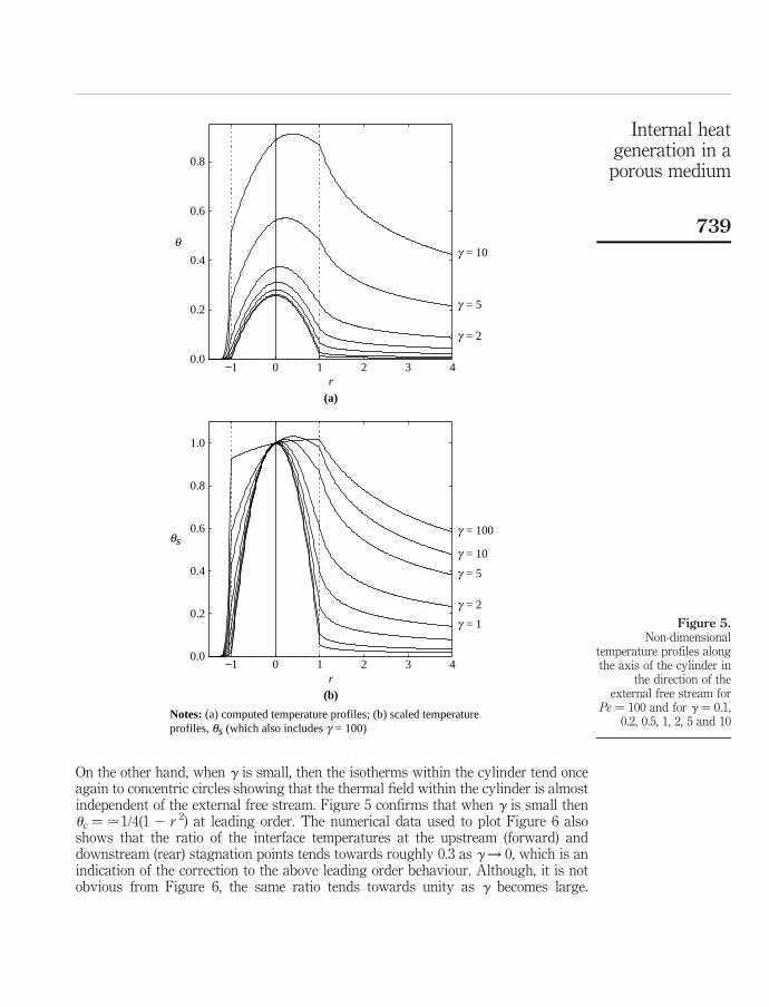
On the other hand, when g is small, then the isotherms within the cylinder tend onceagain to concentric circles showing that the thermal field within the cylinder is almostindependent of the external free stream. Figure 5 confirms that when g is small thenuc ¼ .1/4(1 2 r 2) at leading order. The numerical data used to plot Figure 6 alsoshows that the ratio of the interface temperatures at the upstream (forward) anddownstream (rear) stagnation points tends towards roughly 0.3 as g! 0, which is anindication of the correction to the above leading order behaviour. Although, it is notobvious from Figure 6, the same ratio tends towards unity as g becomes large.
Figure 5.Non-dimensional
temperature profiles alongthe axis of the cylinder in
the direction of theexternal free stream for
Pe ¼ 100 and for g ¼ 0.1,0.2, 0.5, 1, 2, 5 and 10
g = 10
g = 5
g = 2
−1 0 1 2 3 4r
0.0
0.2
0.4
0.6
0.8
q
(a)
g = 100
g = 10
g = 2
g = 1
g = 5
r
0.0
0.2
0.4
0.6
0.8
−1 0
Notes: (a) computed temperature profiles; (b) scaled temperatureprofiles, qs (which also includes g = 100)
1 2 3 4
1.0
qs
(b)
Internal heatgeneration in aporous medium
739

Figure 6.Non-dimensionaltemperature profiles alongthe surface of the cylinderfrom the rear stagnationpoint at f/p ¼ 1
0.0 0.2 0.4 0.6 1.00.8
0.0
0.2
0.4
0.6
0.8
1.0
g = 10
g = 5
g = 2
f / p
q
Notes: The parameters are given by Pe = 100 and g = 0.1, 0.2,0.5, 1, 2, 5 and 10. The dashed line denotes the horizontal axis
Figure 7.the effect of differentvalues of the conductivityratio g on the isothermsfor Pe ¼ 1
g = 10
g = 2
g = 0.5
g = 5
g = 1
g = 0.2
HFF18,6
740

The interface temperature profile when g ¼ 100, which is not shown in Figure 6 due tothe magnitude of their values, 6.601 and 7.227, yields a ratio of roughly 0.91. Finally, itis necessary to point out that the overall shape of the external thermal field shown inFigure 4 varies little with g. The apparent relative thickness of the wake region forg ¼ 100 as compared with the g ¼ 0.1 case is due to the fact that an equal number ofisotherms are plotted in each case. When g ¼ 100 most of the temperature variationtakes place within the porous medium, whereas the opposite occurs when g ¼ 0.1.
Figure 8.Non-dimensional
temperature profiles alongthe axis of the cylinder in
the direction of theexternal free stream forPe ¼ 1 and for g ¼ 0.1,
0.2, 0.5, 1, 2, 5 and 10
0.0 5.0 10.0 15.00
2
4
6
8
10
12
(a)
−1.0 0.0 1.0 2.00.0
0.2
0.4
0.6
0.8
1.0
(b)
g = 10
g = 5
g = 2
g = 0.1
g = 0.2
g = 1
g = 0.5
r
q
r
qs
Notes: (a) computed temperature profiles; (b) scaled temperatureprofiles, qs
Internal heatgeneration in aporous medium
741
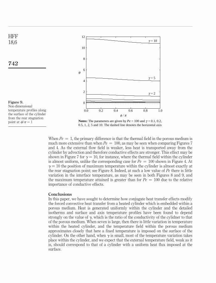
When Pe ¼ 1, the primary difference is that the thermal field in the porous medium ismuch more extensive than when Pe ¼ 100, as may be seen when comparing Figures 7and 4. As the external flow field is weaker, less heat is transported away from thecylinder by advection and therefore conductive effects are stronger. This effect may beshown in Figure 7 for g ¼ 10, for instance, where the thermal field within the cylinderis almost uniform, unlike the corresponding case for Pe ¼ 100 shown in Figure 4. Atg ¼ 10 the position of maximum temperature within the cylinder is almost exactly atthe rear stagnation point; see Figure 8. Indeed, at such a low value of Pe there is littlevariation in the interface temperature, as may be seen in both Figures 8 and 9, andthe maximum temperature attained is greater than for Pe ¼ 100 due to the relativeimportance of conductive effects.
ConclusionsIn this paper, we have sought to determine how conjugate heat transfer effects modifythe forced convective heat transfer from a heated cylinder which is embedded within aporous medium. Heat is generated uniformly within the cylinder and the detailedisotherms and surface and axis temperature profiles have been found to dependstrongly on the value of g, which is the ratio of the conductivity of the cylidner to thatof the porous medium. When seven is large, then there is little variation in temperaturewithin the heated cylinder, and the temperature field within the porous mediumapproximates closely that here a fixed temperature is imposed on the surface of thecylinder. On the other hand, when g is small, most of the temperature variation takesplace within the cylinder, and we expect that the external temperature field, weak as itis, should correspond to that of a cylinder with a uniform heat flux imposed at thesurface.
Figure 9.Non-dimensionaltemperature profiles alongthe surface of the cylinderfrom the rear stagnationpoint at f/p ¼ 1
0.0 0.2 0.4 0.6 0.8 1.0
0
2
4
6
8
10
12g = 10
g = 5
q
g = 2
f / p
Notes: The parameters are given by Pe = 100 and g = 0.1, 0.2,0.5, 1, 2, 5 and 10. The dashed line denotes the horizontal axis
HFF18,6
742

References
Bejan, A. and Kraus, A.D. (Eds) (2003), Heat Transfer Handbook, Wiley, New York, NY.
Bejan, A., Dincer, I., Lorente, S., Miguel, A.F. and Reis, A.H. (2004), Porous and Complex FlowStructures in Modern Technologies, Springer, New York, NY.
Ingham, D.B. and Pop, I. (Eds) (1998), Transport Phenomena in Porous Media Vol. I, Pergamon,Oxford.
Ingham, D.B. and Pop, I. (Eds) (2002), Transport Phenomena in Porous Media Vol. II, Pergamon,Oxford.
Ingham, D.B. and Pop, I. (Eds) (2005), Transport Phenomena in Porous Media Vol. III, Pergamon,Oxford.
Ingham, D.B., Bejan, A., Mamut, E. and Pop, I. (Eds) (2004), Emerging Technologies andTechniques in Porous Media, Kluwer, Dordrecht.
Kimura, S. (1988), “Forced-convection heat-transfer about an elliptic cylinder in a saturatedporous-medium”, Int. J. Heat Mass Transfer, Vol. 31, pp. 197-9.
Kimura, S. (1989), “Transient forced-convection heat-transfer from a circular-cylinder in asaturated porous-medium”, Int. J. Heat Mass Transfer, Vol. 32, pp. 192-5.
Kimura, S. and Pop, I. (1992), “Conjugate free-convection from a circular-cylinder in aporous-medium”, Int. J. Heat Mass Transfer, Vol. 35, pp. 3105-13.
Kimura, S. and Yoneya, M. (1992), “Forced convection heat transfer from a circular cylinder withconstant heat flux in a saturated porous ediu”, Heat Transfer Japanese Research, Vol. 21,pp. 250-8.
Kimura, S., Kiwata, T., Okajima, A. and Pop, I. (1997), “Conjugate natural convection in porousmedia”, Adv. Water Res., Vol. 20, pp. 111-26.
Kloker, M., Konzelmann, U. and Fasel, H. (1993), “Outflow boundary conditions for spatialNavier-Stokes simulations of transitional boundary layers”, AIAA Journal, Vol. 31,pp. 620-8.
Nasr, K., Ramadhyani, S. and Viskanta, R. (1994), “An experimental investigation onforced-convection heat-transfer from a cylinder embedded in a packed-bed”, Trans.A.S.M.E.J. Heat Transfer, Vol. 116, pp. 73-80.
Nield, D.A. and Bejan, A. (2005), Convection in Porous Media, 3rd ed., Springer, Berlin.
Pop, I. and Ingham, D.B. (2001), Convective Heat Transfer: Mathematical and ComputationalModelling of Viscous Fluids and Porous Media, Pergamon, Oxford.
Pop, I. and Nakayama, A. (1999), “Conjugate free and mixed convection heat transfer fromvertical fins embedded in porous media”, in Sunden, B. and Heggs, P.J. (Eds), RecentAdvances in Analysis of Heat Transfer for Fin Type Surfaces, Computational MechanicsPublications, Southampton, pp. 67-96.
Pop, I. and Yan, B. (1998), “Forced convection flow past a circular cylinder and a sphere in aDarcian fluid at large Peclet numbers”, Int. Comm. Heat Mass Transfer, Vol. 25, pp. 261-7.
Rees, D.A.S., Bassom, A.P. and Pop, I. (2003), “Forced convection past a heated cylinder in aporous medium using a thermal nonequilibrium model: boundary layer analysis”,Eur. J. Mech. B-Fluids, Vol. 22, pp. 473-86.
Vafai, K. (Ed.) (2000), Handbook of Porous Media Vol. I, Marcel Dekker, New York, NY.
Vafai, K. (Ed.) (2005), Handbook of Porous Media Vol. II, Marcel Dekker, New York, NY.
Vaszi, A.Z., Elliott, L., Ingham, D.B. and Pop, I. (2003), “Conjugate free convection from verticalfins embedded in a porous medium”, Num. Heat Transfer, Part A, Vol. 44, pp. 743-70.
Internal heatgeneration in aporous medium
743

Vaszi, A.Z., Elliott, L., Ingham, D.B. and Pop, I. (2004), “Conjugate free convection from a verticalplate fin with a rounded tip embedded in a porous medium”, Int. J. Heat Mass Transfer,Vol. 47, pp. 2785-94.
Wong, W.S., Rees, D.A.S. and Pop, I. (2004), “Forced convection past a heated cylinder ina porous medium using a thermal nonequilibrium model: finite Peclet number effects”,Int. J. Thermal Sci., Vol. 43, pp. 213-20.
Corresponding authorD.A.S. Rees can be contacted at: [email protected]
HFF18,6
744
To purchase reprints of this article please e-mail: [email protected] visit our web site for further details: www.emeraldinsight.com/reprints