conjugated polymers based on benzodithiophene for organic ... · conjugated polymers based on...
TRANSCRIPT

Conjugated Polymers Based on Benzodithiophene for Organic Solar Cells
Wei You
Department of Chemistry and
Institute for Advanced Materials, Nanoscience and Technology
University of North Carolina at Chapel Hill
Wake Forest Nanotechnology ConferenceOctober 19, 2009

Modules• 12 % efficiency
• $350/m2
• $3/Wp (from manufacturer)
• $6/Wp (installed)
2
$1/Wp~ $0.05/kWh
Current Industry Leader: Si Solar Cells

DOE numbersAverage cost of PV cell electricity(based on single crystal Si): $.27/kWhToday’s grid electricity: $0.06/kWh
3
Materials Efficiency Materials Cost Installed Cost $/kWh
Poly Si 12‐14% Expensive $4‐6/Wp $0.20‐0.30
CIGS 10‐11% Cheap $4/Wp $0.20
Organic 5‐6% Cheapest $3/Wp or lower $0.15 or lower
$1/Wp~ $0.05/kWh
If the efficiency could be further increased, the $/Wp would be even lower!
Comparison

Advantages of Organic Semiconductor (OSC) Based Photovoltaics Over Inorganic
• Low cost
• Light weight
• Compatible with plastic substrate and can be fabricated using high‐throughput printing techniques (large area; flexible)
• High optical absorption coefficients
• Band gap & energy levels can be fine‐tuned through molecular design
Konarka4
Low Cost Alternative: Organic Solar Cells

5
Excitonic Solar Cell: Donor‐Acceptor Interface

Light absorption(Exciton generation)
Charge collection Charge transfer (Exciton dissociation)
Exciton diffusion
ηEQE = ηA*ηED * ηCT* ηCC
6
Fundamental Physical Processes in OPVIt’s All about Exciton!

Brabec, C. & Durrant, J. MRS Bulletin 2008, 33, 6707
Bulk Heterojunction (BHJ) Polymer Solar Cells
e-
h+
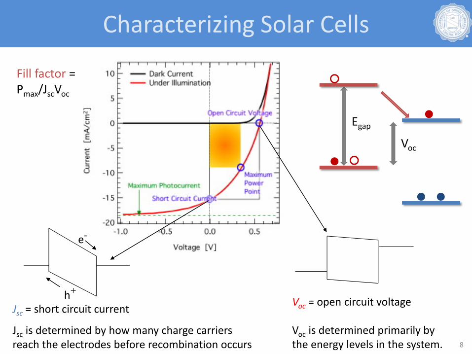
Jsc = short circuit current
Jsc is determined by how many charge carriers reach the electrodes before recombination occurs
Voc = open circuit voltage
Voc is determined primarily bythe energy levels in the system.
Fill factor = Pmax/JscVoc
Voc
Egap
8
Characterizing Solar Cells

External quantum efficiency (he)• Also known as IPCE (incident photon to converted electron) efficiency• Electron out/photons on the device
Internal quantum efficiency (hi) = Electrons out/photons absorbed
hi can be very high in a thin device because the electric field is high and the charge carriers don’t have far to go, but he is low because not many photons are absorbed.
Energy conversion efficiency =
=
electrical power generatedincident optical power
Voc Jsc FFPin
9
Efficiency Definitions

Jsc > 10 mA/cm2
Voc > 0.6 VFF > 65%Efficiency ~ 5%
Yang, Y. et. al. Nature Mater. 2005, 4, 864Heeger, A. J. et. al. Adv. Funct. Mater. 2005, 15, 1617
10
State‐of‐the‐art P3HT/PCBM

Factors:• Band gap• HOMO, LUMO energy level• Morphology
Bundgaard, E. et. al. Solar Energy Materials and Solar Cells 2007, 91, 954‐985. 11
A Bandgap Challenge

S
R
n S n
R
S
S
R
n
1.0‐1.3 eV1.7‐1.9 eV 0.9‐1.0 eV
2. Incorporating more stable quinoid resonance structures in the ground state
S n
R
S n
S
R
12
1. Alternating D‐A in conjugated backbone
D AD A
D+ A‐D+ A‐
“Donor”“Acceptor”
“D‐A” Low BandgapPolymer
Energy (e
V)
‐ 3
‐ 4
‐ 5
‐ 6
LBG
Controlling Bandgap of Conjugated Polymers

Type A
Voc
Egap
Type B
VocEgap
13
Different Types of Low Bandgap Polymers

Best Performing Low Bandgap PolymersHOMO (eV) LUMO (eV) Egap (opt) Voc Jsc FF η % Note
‐ 5.80 ‐ 3.5 1.03 6.3 0.43 2.8 Adv. Funct. Mater. 2006, 16, 667; APL 2007, 91, 071108 (3.5%)
‐ 6.30 ‐ 3.6 1.0 6.0 0.63 3.5 Adv. Funct. Mater. 2007, 17, 3836 (3.5%)
‐ 5.5 ‐ 3.6 1.88 0.89
0.88
6.92
10.6
0.63
0.66
3.6
6.1
(C70)
Adv. Mater. 2007, 19, 2295. JACS 2008, 130 ,732.
Nat. Photon. 2009, 3, 297 (6%)
‐ 5.39 1.82 0.90 9.5 0.507 5.4 APL 2008, 92, 033307.
‐ 5.3 ‐ 3.57 1.40 0.7 9
11
0.47 2.8
3.2 (C70)
Adv. Mater. 2006, 18, 2884.
Nat. Mater. 2007, 7, 497.
Jsc 16.2, Voc 0.62, FF 0.55, efficiency 5.5%, IPCE over 50%
‐ 5.43 ‐ 3.66 1.70 0.80
0.80
6.2
10.1
0.51
0.53
2.5
4.3 (C70)
JACS 2008, 130, 12828.
‐ 5.1 ‐ 3.4 1.7 (film) 0.66
0.61
9.4
11.3
0.47
0.58
2.9
4.0 (C70)
Adv. Mater. 2008, 20, 2556.
‐ 5.05 ‐ 3.27 1.45 0.68 12.7 0.55 5.1 (C70)
JACS 2008, 130, 16144.
‐ 4.90 ‐ 3.20 1.62 (film)
0.58
0.56
12.5
15.0
0.654
0.633
4.76
5.30 (C70)
JACS 2009, 131, 56.
JACS 2009, 131, 7792 (6.1%)

Energy (e
V)
‐ 3
‐ 4
‐ 5
‐ 6P3HT
“Ideal” Polymer PCBM
3.3
5.2
4.2
6.0
5.4
3.9
Weak donor
• Absorption
• Energy Level
• Morphology
• Low band gap• Broad absorption
Jsc (upper limit)
Voc
Jsc (attainable) FF
• Low HOMO level• Minimize voltage lost at electrodes
• Maximize D/A interface• High mobility & balanced• Biphasic
“Donor”
“Acceptor”
Strong acceptor
Weak donor Strong acceptorn 15
“Ideal” Polymer?

- 3.9
1.5
“Ideal” Polymer
P3HT
Scharber, M. C. et.al. Adv. Mater. 2006, 18, 789‐794
FF: 0.65IPCE: 65%
16
10% Possible?

• Fused ring: Increased π conjugation• π ‐ π stacking: mobility• Tuning HOMO level!
17
Fused Thiophenes
π

18
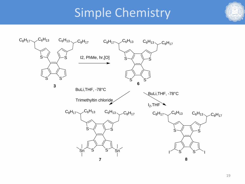
A Case Study of Benzodithiophene Series
S S
S
C6H13 C8H17
S
C6H13C8H17
6
S S
S
C6H13 C8H17
S
C6H13C8H17
I IS S
S
C6H13 C8H17
S
C6H13C8H17
Sn Sn
7 8
S S
S
C6H13 C8H17
S
C6H13C8H17
3
I2, PhMe, hr,[O]
BuLi,THF, -78°C
I2,THF
BuLi,THF, -78°C
Trimethyltin chloride
19
Simple Chemistry

S S
S
C6H13 C8H17
S
C6H13C8H17
Sn Sn7
S S
S
C6H13 C8H17
S
C6H13C8H17
I I8
S S
S
C6H13 C8H17
S
C6H13C8H17
n
Pd(PPh3)4PhMeReflux,Ar3days
HMPQTN
S S
S
C6H13 C8H17
S
C6H13C8H17
NSN
nS S
S
C6H13 C8H17
S
C6H13C8H17
Sn Sn7
Br Br
NS
N
+Pd(PPh3)4PhMeReflux,Ar24h
PQTN-BT
+
20
More Polymers

300 400 500 600 700 800 900 10000.00
0.05
0.10
0.15
0.20
0.25
HMPQTN PQTN-BT
Abs
orpt
ion
Wavelength (nm)
0.005mg/mL in CHCl3 at room temperature 21
Solution Absorption

300 400 500 600 700 800 9000.00
0.05
0.10
0.15
0.20
0.25
HMPQTN PQTN-BT
Abs
orpt
ion
Wavelength (nm)
Films of polymers from the solutions in PhCl3 at room temperature with thickness around 40‐60nm.
22
Film Absorption
Uv‐Vis absorption data Cyclic Voltammetry TD‐DFT
CHCl3 solution Film [V]
HOMO [eV]
[V]
LUMO [eV]
Calculated HOMO [eV}polymer
λmax[nm]
λonset[nm]
Eg[eV]
λmax [nm]
λonset[nm]
Eg[eV]
HMPQTN 573,530 612 2.04 592,545 620 2.0 0.58/‐5.38 NA/‐3.34 ‐5.38
PQTN‐BT 716,657 770 1.61 714,652 775 1.61 0.58/‐5.38 NA/‐3.77 ‐5.33
oxonestE
redonestE

HOMO LUMOHMPQTN
PQTN‐BT LUMOHOMO
23
Calculated HOMO/LUMO

- 3.9
1.5
FF: 0.65IPCE: 65%
HMPQTN
PQTN‐BT
24
What Might Be Achievable?

25
0.0 0.2 0.4 0.6 0.8 1.0 1.2-6
-4
-2
0
2
4
6
8
10
Cur
rent
Den
sity
(mA
/cm
2 )
Voltage (V)
HMPQTN (light) HMPQTN (dark)
400 450 500 550 600 6500.0
0.1
0.2
0.3
0.4
0.5
0
5
10
15
20
25
30
35
40
45
Abs
orba
nce
(a. u
.)
Wavelength (nm)
EQE
(%)
HMPQTN: PCBM = 1:2, 180 nm thick film
Voc ‐ 0.76 VJsc ‐ 5.02 mA/cm‐2
FF ‐ 53.08%η ‐ 2.03%
Optimized Devices

26
0.0 0.2 0.4 0.6 0.8 1.0 1.2-6
-4
-2
0
2
4
6
8
10
Cur
rent
Den
sity
(mA
/cm
2 )
Voltage (V)
PQTN-BT (light) PQTN-BT (dark)
400 450 500 550 600 650 700 750 8000.00
0.05
0.10
0.15
0
5
10
15
20
25
30
35
40
Abs
orba
nce
(a. u
.)
Wavelength (nm)
EQE
(%)
PQTN‐BT: PCBM = 1:2, 80 nm thick film
Voc ‐ 0.72 VJsc ‐ 5.69 mA/cm‐2
FF ‐ 50.26%η ‐ 2.06%
Optimized Devices

27
PolymerPCBM /Polym
er
Film Thickness (nm)
Voc (V)Js
(mA/cm2)FF η (%)
Mobility (cm2/V∙s)
HMPQTN 2:1 55 0.60 2.1 36 0.45
2:1 70 0.76 2.42 41 0.76
2:1 180 0.76 5.02 53.08 2.03 8.2×10‐5
200 0.72 3.7 50.57 1.35
PQTN‐BT 2:1 45 0.72 3.91 49.06 1.38
2:1 55 0.74 5.97 39.52 1.75
2:1 80 0.72 5.69 50.26 2.06 1.3×10‐5
115 0.60 2.18 37.46 0.49
Performance vs. Thickness

• “Ideal” polymers require low HOMO level (maximize Voc) and low bandgap (maximize Jsc) (when PCBM is used)
• Combining weak donor and strong acceptor would potentially lead to “ideal” polymers for OSC
• Mobility and morphology are crucial to approach the theoretical efficiency: attainable Jsc and FF
• Polycyclic, fused aromatic molecules are excellent building blocks for “ideal” polymers
(a) effectively lower the HOMO (b) improved π‐π interactions between polymer chains in thin
solid films would enhance the charge carrier mobility28
Conclusions
29
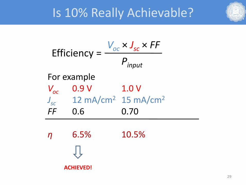
For exampleVoc 0.9 V 1.0 VJsc 12 mA/cm2 15 mA/cm2
FF 0.6 0.70
η 6.5% 10.5%
Voc × Jsc × FFEfficiency =Pinput
Is 10% Really Achievable?
ACHIEVED!

Acknowledgments
The You Group:
Sam Price (4th yr)
Jeremy Niskala (4th yr)
Andrew Stuart (3rd yr)
Huaxing Zhou (3rd yr)
Rycel Uy (2nd yr)
Liqiang Yang (2nd yr)
Sarah Stoneking (undergraduate)
Nabil Kleinhenz (undergraduate)
Dr. Shubin Liu
$$ Support:
30