connecting your editing equipment - avid technology
TRANSCRIPT

Part 0130-04419-01 Rev. A Connecting Your Editing Equipment
a
This document describes how to connect editing equipment to the IBM® IntelliStation® on which the Avid Xpress™ DV software will run. This document contains the following topics:
• Connecting the External SCSI Drives
• Connecting the Application Key
• Connecting the Editing Equipment
Connecting Your Editing Equipment
for the Avid Xpress™ DV Software
2 Connecting Your Editing Equipment
Connecting Your Editing Equipment Part 0130-04419-01 Rev. A
Contents
Symbols and Conventions . . . . . . . . . . . . . . . . . . . . . . . . . . . . . . . . . . . . . 2Connecting the External SCSI Drives. . . . . . . . . . . . . . . . . . . . . . . . . . . . 3
Installation Overview . . . . . . . . . . . . . . . . . . . . . . . . . . . . . . . . . . . . . 3Placing the Drives . . . . . . . . . . . . . . . . . . . . . . . . . . . . . . . . . . . . . . . . 4Cabling the Drives . . . . . . . . . . . . . . . . . . . . . . . . . . . . . . . . . . . . . . . . 5Determining the SCSI IDs. . . . . . . . . . . . . . . . . . . . . . . . . . . . . . . . . 10Setting the SCSI IDs. . . . . . . . . . . . . . . . . . . . . . . . . . . . . . . . . . . . . . 11
Connecting the Application Key . . . . . . . . . . . . . . . . . . . . . . . . . . . . . . 13Connecting the Editing Equipment . . . . . . . . . . . . . . . . . . . . . . . . . . . . 14
Overview of the Hardware Connections . . . . . . . . . . . . . . . . . . . . 15Cables Needed to Connect the Equipment . . . . . . . . . . . . . . . . . . 16
Cables Shipped with the IntelliStation . . . . . . . . . . . . . . . . . . .16Optional Cables . . . . . . . . . . . . . . . . . . . . . . . . . . . . . . . . . . . . . .17
Connecting a Digital Video Deck or Camera to the IntelliStation . . . . . . . . . . . . . . . . . . . . . . . . . . . . . . . . . . . . . . . . . . 18
Connecting an Analog Video Deck to the IntelliStation . . . . . . . 21Controlling an Analog Video Deck. . . . . . . . . . . . . . . . . . . . . . . . . 24
Symbols and Conventions
This document uses the following special symbols and conventions:
n A note provides important related information, reminders, recommendations, and strong suggestions.
c A caution means that a specific action you take could cause harm to your computer or cause you to lose data.
Connecting Your Editing Equipment 3
Part 0130-04419-01 Rev. A Connecting Your Editing Equipment
Connecting the External SCSI Drives
This section explains how to connect external SCSI drives to your Ultra2 LVD/SE SCSI board located at the rear of your IntelliStation. Because the Ultra2 LVD/SE SCSI board has a 68-pin, high-density connector, illustrations of SCSI drives show 68-pin, high-density connectors.
n If you purchased drives other than the illustrated ones, use the instructions that came with your drives.
This section contains:
• Installation Overview
• Placing the Drives
• Cabling the Drives
• Determining the SCSI IDs
• Setting the SCSI IDs
Installation Overview
Installing external SCSI drives is not very difficult; however, you must consider the following:
• Place the drives near your IntelliStation to save space, and posi-tion the drives so they can’t fall over.
• Cable the drives from your IntelliStation to the last drive in the chain, and terminate the last drive.
• Determine the SCSI IDs before you physically set them on the drive.
• Set the SCSI IDs so the system software and the Avid Xpress DV software can access them.

4 Connecting Your Editing Equipment
Connecting Your Editing Equipment Part 0130-04419-01 Rev. A
Placing the Drives
Placing the external drives is an important part of the installation. When you place the external drives, consider the following:
• Place the drives close to the IntelliStation. There is a maximum cable-length restriction of 20 feet when you use wide-type drives.
• Do not place the drives on the floor. They can pick up dust and dirt from the floor or carpet.
• When you have more than one external drive, you can stack the drives so they take up a minimal amount of desk space. If you use more than four drives, consider creating two drive stacks (see Figure 1).
c You should not stack more than four external SCSI drives.
Figure 1 Placing the External SCSI Drives
4
4
4
4
Two stacks of four drives
4
4
4
4
Connecting Your Editing Equipment 5
Part 0130-04419-01 Rev. A Connecting Your Editing Equipment
Cabling the Drives
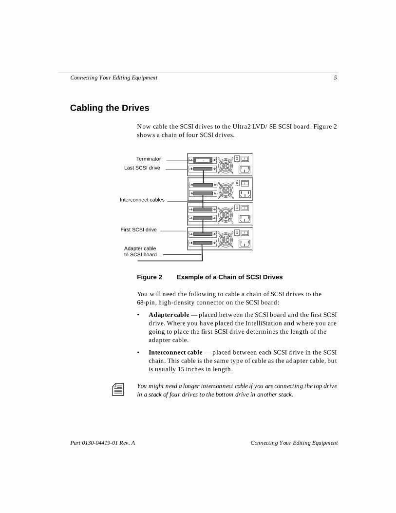
Now cable the SCSI drives to the Ultra2 LVD/SE SCSI board. Figure 2 shows a chain of four SCSI drives.
Figure 2 Example of a Chain of SCSI Drives
You will need the following to cable a chain of SCSI drives to the 68-pin, high-density connector on the SCSI board:
• Adapter cable — placed between the SCSI board and the first SCSI drive. Where you have placed the IntelliStation and where you are going to place the first SCSI drive determines the length of the adapter cable.
• Interconnect cable — placed between each SCSI drive in the SCSI chain. This cable is the same type of cable as the adapter cable, but is usually 15 inches in length.
n You might need a longer interconnect cable if you are connecting the top drive in a stack of four drives to the bottom drive in another stack.
4
4
4
4
Adapter cable
Interconnect cables
Terminator
First SCSI drive
Last SCSI drive
to SCSI board
6 Connecting Your Editing Equipment
Connecting Your Editing Equipment Part 0130-04419-01 Rev. A
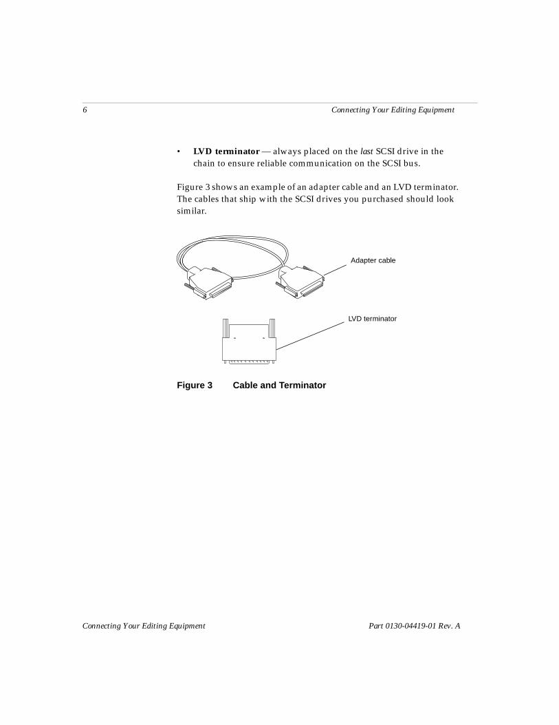
• LVD terminator — always placed on the last SCSI drive in the chain to ensure reliable communication on the SCSI bus.
Figure 3 shows an example of an adapter cable and an LVD terminator. The cables that ship with the SCSI drives you purchased should look similar.
Figure 3 Cable and Terminator
Adapter cable
LVD terminator
Connecting Your Editing Equipment 7
Part 0130-04419-01 Rev. A Connecting Your Editing Equipment
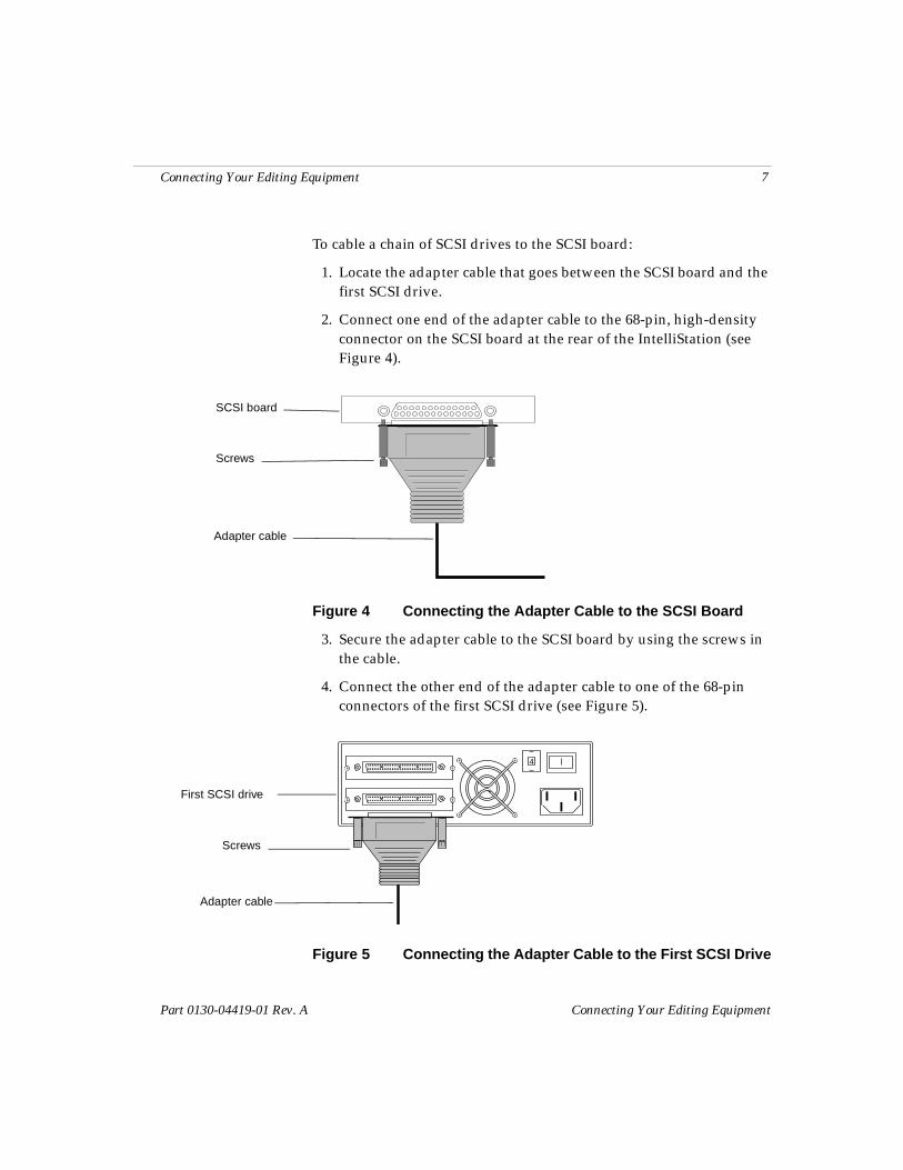
To cable a chain of SCSI drives to the SCSI board:
1. Locate the adapter cable that goes between the SCSI board and the first SCSI drive.
2. Connect one end of the adapter cable to the 68-pin, high-density connector on the SCSI board at the rear of the IntelliStation (see Figure 4).
Figure 4 Connecting the Adapter Cable to the SCSI Board
3. Secure the adapter cable to the SCSI board by using the screws in the cable.
4. Connect the other end of the adapter cable to one of the 68-pin connectors of the first SCSI drive (see Figure 5).
Figure 5 Connecting the Adapter Cable to the First SCSI Drive
SCSI board
Adapter cable
Screws
4
Adapter cable
Screws
First SCSI drive
8 Connecting Your Editing Equipment
Connecting Your Editing Equipment Part 0130-04419-01 Rev. A
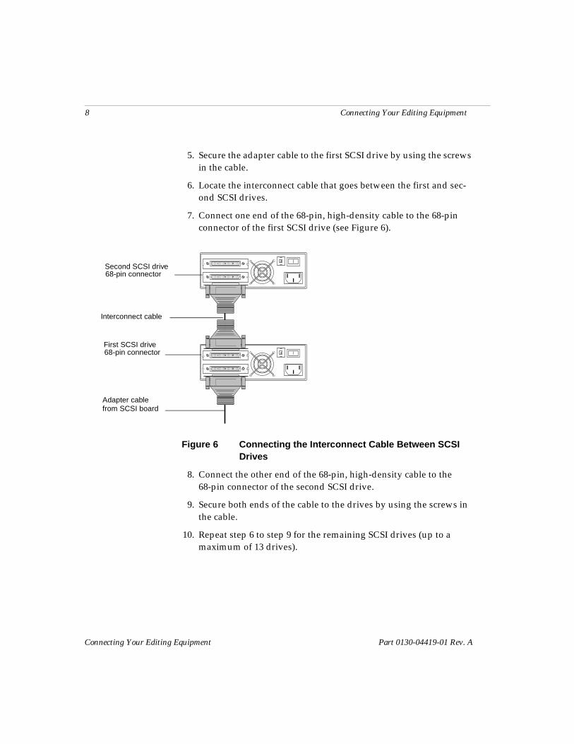
5. Secure the adapter cable to the first SCSI drive by using the screws in the cable.
6. Locate the interconnect cable that goes between the first and sec-ond SCSI drives.
7. Connect one end of the 68-pin, high-density cable to the 68-pin connector of the first SCSI drive (see Figure 6).
Figure 6 Connecting the Interconnect Cable Between SCSI Drives
8. Connect the other end of the 68-pin, high-density cable to the 68-pin connector of the second SCSI drive.
9. Secure both ends of the cable to the drives by using the screws in the cable.
10. Repeat step 6 to step 9 for the remaining SCSI drives (up to a maximum of 13 drives).
4
4
Interconnect cable
First SCSI drive
Second SCSI drive
68-pin connector
68-pin connector
Adapter cablefrom SCSI board
Connecting Your Editing Equipment 9
Part 0130-04419-01 Rev. A Connecting Your Editing Equipment
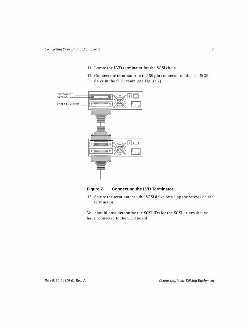
11. Locate the LVD terminator for the SCSI chain.
12. Connect the terminator to the 68-pin connector on the last SCSI drive in the SCSI chain (see Figure 7).
Figure 7 Connecting the LVD Terminator
13. Secure the terminator to the SCSI drive by using the screws on the terminator.
You should now determine the SCSI IDs for the SCSI drives that you have connected to the SCSI board.
4
4Terminator
Last SCSI drive
Screws
10 Connecting Your Editing Equipment
Connecting Your Editing Equipment Part 0130-04419-01 Rev. A
Determining the SCSI IDs
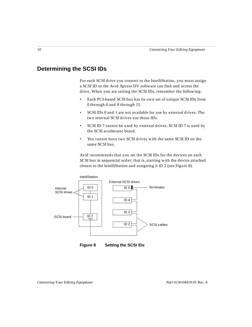
For each SCSI drive you connect to the IntelliStation, you must assign a SCSI ID so the Avid Xpress DV software can find and access the drive. When you are setting the SCSI IDs, remember the following:
• Each PCI-based SCSI bus has its own set of unique SCSI IDs from 0 through 6 and 8 through 15.
• SCSI IDs 0 and 1 are not available for use by external drives. The two internal SCSI drives use those IDs.
• SCSI ID 7 cannot be used by external drives. SCSI ID 7 is used by the SCSI accelerator board.
• You cannot have two SCSI drives with the same SCSI ID on the same SCSI bus.
Avid recommends that you set the SCSI IDs for the devices on each SCSI bus in sequential order; that is, starting with the device attached closest to the IntelliStation and assigning it ID 2 (see Figure 8).
Figure 8 Setting the SCSI IDs
ID 7SCSI board
IntelliStation
External SCSI drives
Terminator
SCSI cablesID 2
ID 3
ID 4
ID 5ID 0
ID 1
InternalSCSI drives
Connecting Your Editing Equipment 11
Part 0130-04419-01 Rev. A Connecting Your Editing Equipment
Setting the SCSI IDs
The following illustrations show how to set a SCSI ID by using a wide-type SCSI drive with switches and connections at the rear of the drives. If the drives you purchased do not look like the drives shown in the illustrations, use the installation instructions that came with the drives you purchased.
n If you are using the SCSI installations instructions that came with your drives, you still need to use the information in “Determining the SCSI IDs” on page 10.
To set a SCSI ID:
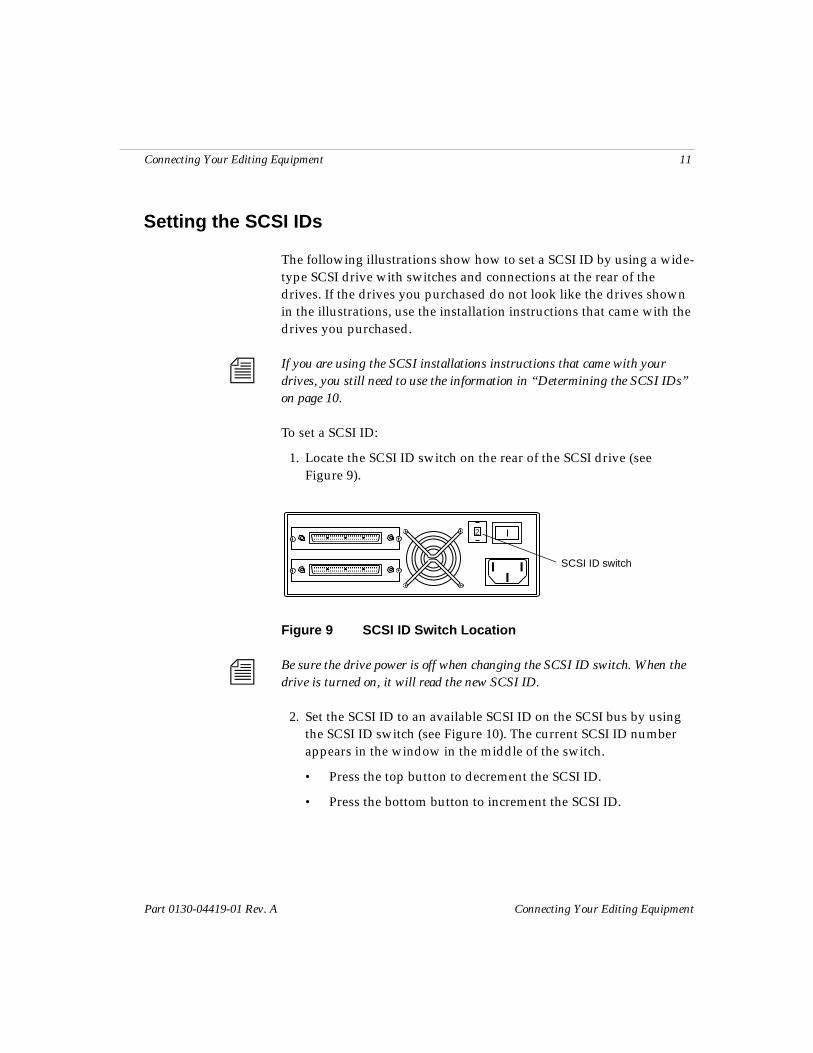
1. Locate the SCSI ID switch on the rear of the SCSI drive (see Figure 9).
Figure 9 SCSI ID Switch Location
n Be sure the drive power is off when changing the SCSI ID switch. When the drive is turned on, it will read the new SCSI ID.
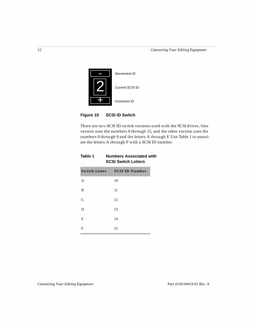
2. Set the SCSI ID to an available SCSI ID on the SCSI bus by using the SCSI ID switch (see Figure 10). The current SCSI ID number appears in the window in the middle of the switch.
• Press the top button to decrement the SCSI ID.
• Press the bottom button to increment the SCSI ID.
2
SCSI ID switch
12 Connecting Your Editing Equipment
Connecting Your Editing Equipment Part 0130-04419-01 Rev. A
Figure 10 SCSI ID Switch
There are two SCSI ID switch versions used with the SCSI drives. One version uses the numbers 0 through 15, and the other version uses the numbers 0 through 9 and the letters A through F. Use Table 1 to associ-ate the letters A through F with a SCSI ID number.
2-
+
Decrement ID
Increment ID
Current SCSI ID
Table 1 Numbers Associated with SCSI Switch Letters
Switch Letter SCSI ID Number
A 10
B 11
C 12
D 13
E 14
F 15
Connecting Your Editing Equipment 13
Part 0130-04419-01 Rev. A Connecting Your Editing Equipment
Connecting the Application Key
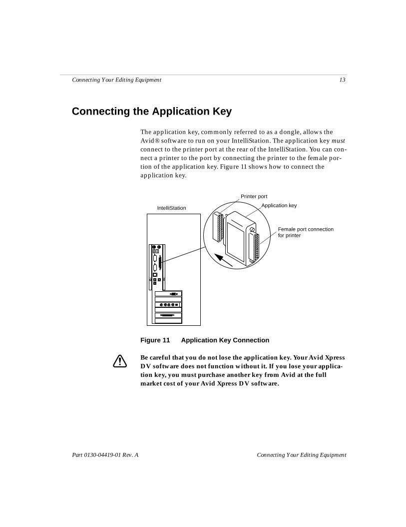
The application key, commonly referred to as a dongle, allows the Avid® software to run on your IntelliStation. The application key must connect to the printer port at the rear of the IntelliStation. You can con-nect a printer to the port by connecting the printer to the female por-tion of the application key. Figure 11 shows how to connect the application key.
Figure 11 Application Key Connection
c Be careful that you do not lose the application key. Your Avid Xpress DV software does not function without it. If you lose your applica-tion key, you must purchase another key from Avid at the full market cost of your Avid Xpress DV software.
Application key
Female port connection
IntelliStation
Printer port
for printer
14 Connecting Your Editing Equipment
Connecting Your Editing Equipment Part 0130-04419-01 Rev. A
Connecting the Editing Equipment
Make sure that you have completed the setup information provided in the Read Me First sheet that shipped with your IntelliStation. The Read Me First sheet provides instructions for setting up your IntelliStation, and attaching the monitor, keyboard, and mouse.
c Make sure that your IntelliStation is turned off before you connect the rest of the equipment.
Your editing equipment might be a camera, a digital video deck, or an analog video deck connected to a transcoder. This section provides illustrations and instructions to help you connect the cables between the editing equipment and the IntelliStation.
n The cameras, video decks, and transcoders in the illustrations represent the type of equipment supported by Avid Xpress DV. Therefore, the illustrations show cables that came with the camera, transcoder, video deck, or capture board. You can also purchase other cables from a local audio or video store.
This section is divided into five parts:
• Overview of the Hardware Connections
• Cables Needed to Connect the Equipment
• Connecting a Digital Video Deck or Camera to the IntelliStation
• Connecting an Analog Video Deck to the IntelliStation
• Controlling an Analog Video Deck
n See the Avid Xpress DV Getting Started Guide for a list of currently sup-ported cameras, transcoders, and video decks. As new equipment appears on the market, Avid will provide an up-to-date list of supported cameras, transcoders, and video decks in the Avid Customer Service Knowledge Center at http://www.avid.com.
Connecting Your Editing Equipment 15
Part 0130-04419-01 Rev. A Connecting Your Editing Equipment
Overview of the Hardware Connections
The type of data (digital or analog) you transfer between the editing equipment and the IntelliStation is used for different purposes by Avid Xpress DV. You should think of the data being transferred in terms of how it is being used.
• Digital video and digital audio (DV) — used for editing pur-poses. These signals come from either a digital video deck, a digi-tal camera, or a transcoder connected to an analog video deck using a 4-pin to 4-pin IEEE 1394 cable (see Figure 12) attached to the capture board plugged into your IntelliStation. As an output, the DV signals can be recorded and used to control a digital video deck or camera.
• Analog video — not used for editing purposes. These signals come from a digital video deck, camera, or transcoder to the cap-ture board. The capture board then loops the analog video to an optional Client monitor. This process allows you to monitor the video as you record the data or output the data. There are two forms of analog data (see Figure 12):
- Composite video using RCA® connectors
- S-Video using S-Video connectors
n The analog connection is also used when your camera or transcoder is connected to the IntelliStation and you play a clip from the Avid Xpress DV software. See Table 2 step 2 for more information.
• Analog audio — not used for editing purposes. The analog audio output of a digital video deck, camera, or a transcoder connects to the audio input at the rear of the IntelliStation. You can hear the analog audio through the speakers during the record process or when you play back the clips using the software.
16 Connecting Your Editing Equipment
Connecting Your Editing Equipment Part 0130-04419-01 Rev. A
Cables Needed to Connect the Equipment
You need cables to connect the IntelliStation to the camera, digital video deck, or transcoder used with an analog video deck. You receive some or all of these cables when you purchase most digital video decks, digital cameras, or transcoders. Because Avid Xpress DV sup-ports many digital cameras, the number and type of cables you receive cannot be determined. Given this fact, this section describes:
• Cables that ship with the Avid Xpress DV software and IntelliStation, and how to connect them to either a camera or transcoder
• Other cables, and what they are used for, in case you buy an optional transcoder, Client monitor, or analog video deck
n The cameras, video decks, and transcoders in the illustrations represent the type of equipment supported by Avid Xpress DV. Therefore, the illustrations show cables that came with the camera, transcoder, video deck, or capture board. You can also purchase other cables from a local audio or video store.
Cables Shipped with the IntelliStation
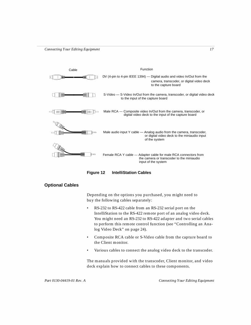
Figure 12 shows the cables shipped with the IntelliStation and their functions.
Connecting Your Editing Equipment 17
Part 0130-04419-01 Rev. A Connecting Your Editing Equipment
Figure 12 IntelliStation Cables
Optional Cables
Depending on the options you purchased, you might need to buy the following cables separately:
• RS-232 to RS-422 cable from an RS-232 serial port on the IntelliStation to the RS-422 remote port of an analog video deck. You might need an RS-232 to RS-422 adapter and two serial cables to perform this remote control function (see “Controlling an Ana-log Video Deck” on page 24).
• Composite RCA cable or S-Video cable from the capture board to the Client monitor.
• Various cables to connect the analog video deck to the transcoder.
The manuals provided with the transcoder, Client monitor, and video deck explain how to connect cables to these components.
Male audio input Y cable — Analog audio from the camera, transcoder,
Cable Function
S-Video — S-Video In/Out from the camera, transcoder, or digital video deck
Male RCA — Composite video In/Out from the camera, transcoder, or
Female RCA Y cable — Adapter cable for male RCA connectors from
DV (4-pin to 4-pin IEEE 1394) — Digital audio and video In/Out from the
digital video deck to the input of the capture board
or digital video deck to the miniaudio input
the camera or transcoder to the miniaudio input of the system
camera, transcoder, or digital video deck
to the input of the capture board
to the capture board
of the system
18 Connecting Your Editing Equipment
Connecting Your Editing Equipment Part 0130-04419-01 Rev. A
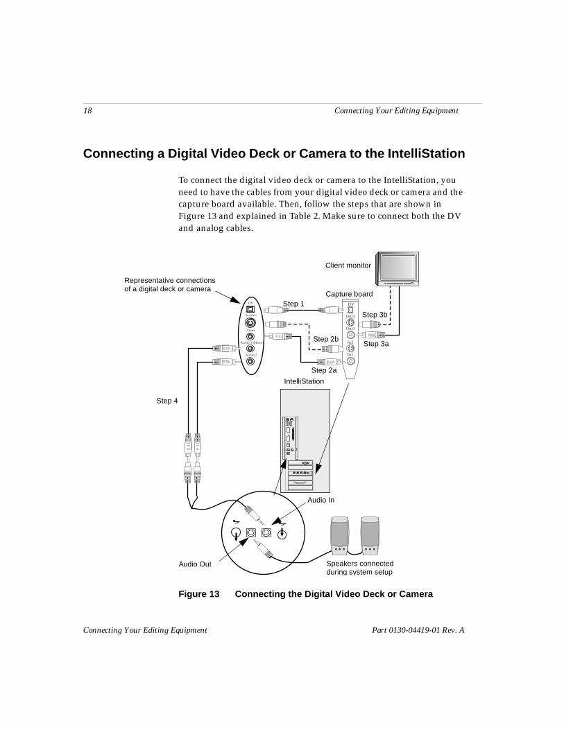
Connecting a Digital Video Deck or Camera to the IntelliStation
To connect the digital video deck or camera to the IntelliStation, you need to have the cables from your digital video deck or camera and the capture board available. Then, follow the steps that are shown in Figure 13 and explained in Table 2. Make sure to connect both the DV and analog cables.
Figure 13 Connecting the Digital Video Deck or Camera
DV
Out2
Out1
In2
In1
S-video
Video
Audio 1 (Mono)
Audio 2
DV Step 1
Step 2a
Step 3a
Step 4
IntelliStation
Speakers connected
Step 2b
during system setup
Step 3b
Audio In
Audio Out
Representative connectionsof a digital deck or camera
Capture board
Client monitor
Connecting Your Editing Equipment 19
Part 0130-04419-01 Rev. A Connecting Your Editing Equipment
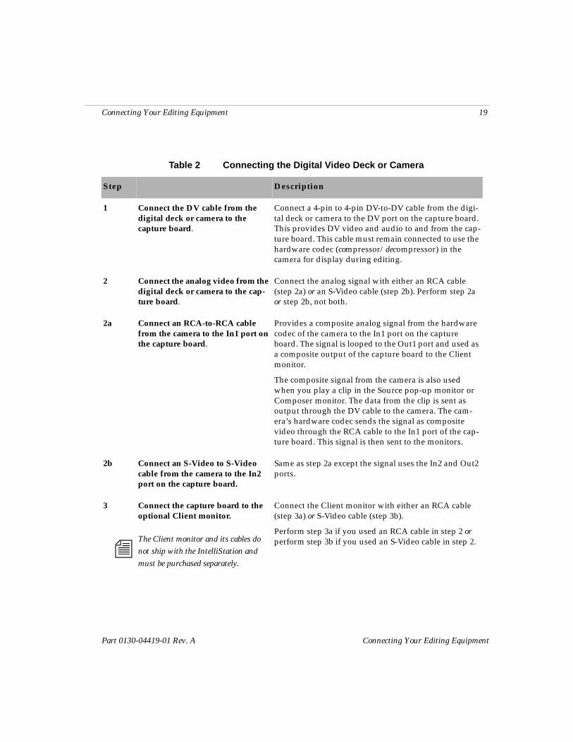
Table 2 Connecting the Digital Video Deck or Camera
Step Description
1 Connect the DV cable from the digital deck or camera to the capture board.
Connect a 4-pin to 4-pin DV-to-DV cable from the digi-tal deck or camera to the DV port on the capture board. This provides DV video and audio to and from the cap-ture board. This cable must remain connected to use the hardware codec (compressor/decompressor) in the camera for display during editing.
2 Connect the analog video from the digital deck or camera to the cap-ture board.
Connect the analog signal with either an RCA cable (step 2a) or an S-Video cable (step 2b). Perform step 2a or step 2b, not both.
2a Connect an RCA-to-RCA cable from the camera to the In1 port on the capture board.
Provides a composite analog signal from the hardware codec of the camera to the In1 port on the capture board. The signal is looped to the Out1 port and used as a composite output of the capture board to the Client monitor.
The composite signal from the camera is also used when you play a clip in the Source pop-up monitor or Composer monitor. The data from the clip is sent as output through the DV cable to the camera. The cam-era’s hardware codec sends the signal as composite video through the RCA cable to the In1 port of the cap-ture board. This signal is then sent to the monitors.
2b Connect an S-Video to S-Video cable from the camera to the In2 port on the capture board.
Same as step 2a except the signal uses the In2 and Out2 ports.
3
n
Connect the capture board to the optional Client monitor.
The Client monitor and its cables do not ship with the IntelliStation and must be purchased separately.
Connect the Client monitor with either an RCA cable (step 3a) or S-Video cable (step 3b).
Perform step 3a if you used an RCA cable in step 2 or perform step 3b if you used an S-Video cable in step 2.
20 Connecting Your Editing Equipment
Connecting Your Editing Equipment Part 0130-04419-01 Rev. A
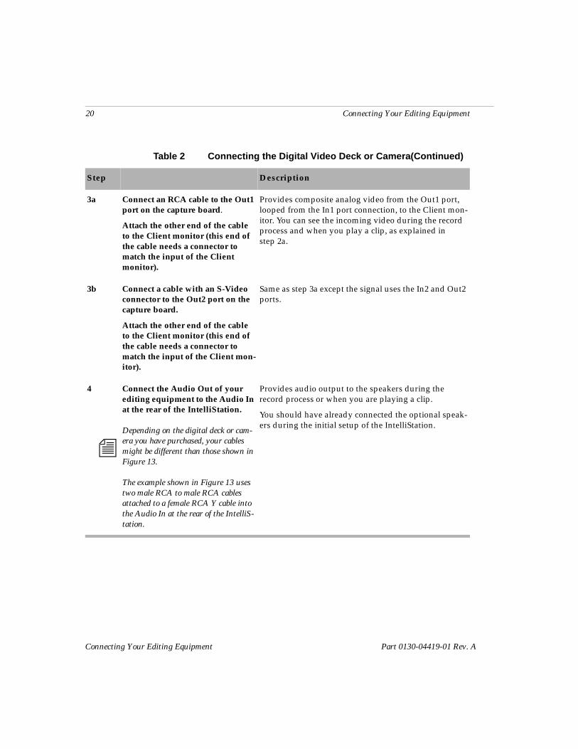
3a Connect an RCA cable to the Out1 port on the capture board.
Attach the other end of the cable to the Client monitor (this end of the cable needs a connector to match the input of the Client monitor).
Provides composite analog video from the Out1 port, looped from the In1 port connection, to the Client mon-itor. You can see the incoming video during the record process and when you play a clip, as explained in step 2a.
3b Connect a cable with an S-Video connector to the Out2 port on the capture board.
Attach the other end of the cable to the Client monitor (this end of the cable needs a connector to match the input of the Client mon-itor).
Same as step 3a except the signal uses the In2 and Out2 ports.
4
n
Connect the Audio Out of your editing equipment to the Audio In at the rear of the IntelliStation.
Depending on the digital deck or cam-era you have purchased, your cables might be different than those shown in Figure 13.
The example shown in Figure 13 uses two male RCA to male RCA cables attached to a female RCA Y cable into the Audio In at the rear of the IntelliS-tation.
Provides audio output to the speakers during the record process or when you are playing a clip.
You should have already connected the optional speak-ers during the initial setup of the IntelliStation.
Table 2 Connecting the Digital Video Deck or Camera(Continued)
Step Description
Connecting Your Editing Equipment 21
Part 0130-04419-01 Rev. A Connecting Your Editing Equipment
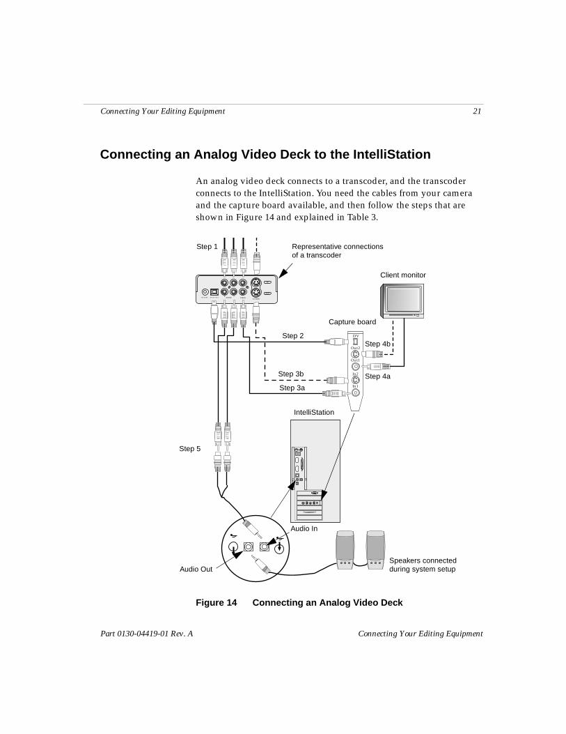
Connecting an Analog Video Deck to the IntelliStation
An analog video deck connects to a transcoder, and the transcoder connects to the IntelliStation. You need the cables from your camera and the capture board available, and then follow the steps that are shown in Figure 14 and explained in Table 3.
Figure 14 Connecting an Analog Video Deck
IN
OUT
S-VIDEOVIDEOAUDIODV IN / OUTDC IN 6V
LR
DV
Out2
Out1
In2
In1
Step 1
Step 2
Step 3a
Step 3b Step 4a
Step 4b
Step 5
Speakers connected during system setupAudio Out
Audio In
Capture board
Client monitor
Representative connectionsof a transcoder
IntelliStation
22 Connecting Your Editing Equipment
Connecting Your Editing Equipment Part 0130-04419-01 Rev. A
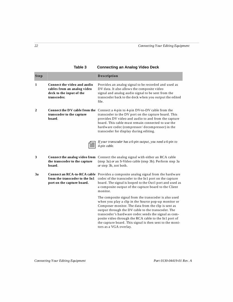
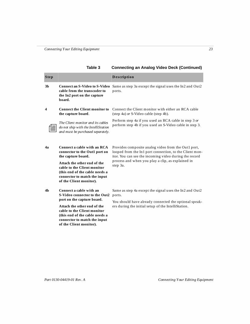
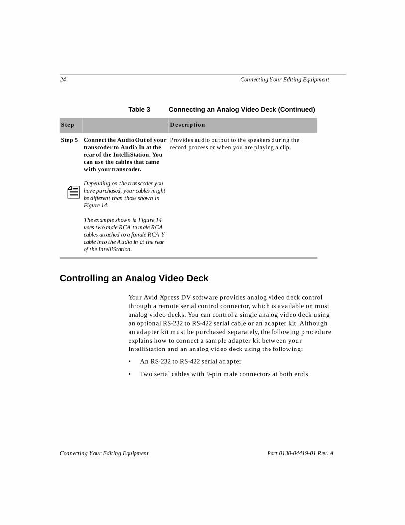
Table 3 Connecting an Analog Video Deck
Step Description
1 Connect the video and audio cables from an analog video deck to the input of the transcoder.
Provides an analog signal to be recorded and used as DV data. It also allows the composite video signal and analog audio signal to be sent from the transcoder back to the deck when you output the edited file.
2 Connect the DV cable from the transcoder to the capture board.
n
Connect a 4-pin to 4-pin DV-to-DV cable from the transcoder to the DV port on the capture board. This provides DV video and audio to and from the capture board. This cable must remain connected to use the hardware codec (compressor/decompressor) in the transcoder for display during editing.
If your transcoder has a 6-pin output, you need a 6-pin to 4-pin cable.
3 Connect the analog video from the transcoder to the capture board.
Connect the analog signal with either an RCA cable (step 3a) or an S-Video cable (step 3b). Perform step 3a or step 3b, not both.
3a Connect an RCA-to-RCA cable from the transcoder to the In1 port on the capture board.
Provides a composite analog signal from the hardware codec of the transcoder to the In1 port on the capture board. The signal is looped to the Out1 port and used as a composite output of the capture board to the Client monitor.
The composite signal from the transcoder is also used when you play a clip in the Source pop-up monitor or Composer monitor. The data from the clip is sent as output through the DV cable to the transcoder. The transcoder’s hardware codec sends the signal as com-posite video through the RCA cable to the In1 port of the capture board. This signal is then sent to the moni-tors as a VGA overlay.
Connecting Your Editing Equipment 23
Part 0130-04419-01 Rev. A Connecting Your Editing Equipment
3b Connect an S-Video to S-Video cable from the transcoder to the In2 port on the capture board.
Same as step 3a except the signal uses the In2 and Out2 ports.
4
n
Connect the Client monitor to the capture board.
The Client monitor and its cables do not ship with the IntelliStation and must be purchased separately.
Connect the Client monitor with either an RCA cable (step 4a) or S-Video cable (step 4b).
Perform step 4a if you used an RCA cable in step 3 or perform step 4b if you used an S-Video cable in step 3.
4a Connect a cable with an RCA connector to the Out1 port on the capture board.
Attach the other end of the cable to the Client monitor (this end of the cable needs a connector to match the input of the Client monitor).
Provides composite analog video from the Out1 port, looped from the In1 port connection, to the Client mon-itor. You can see the incoming video during the record process and when you play a clip, as explained in step 3a.
4b Connect a cable with an S-Video connector to the Out2 port on the capture board.
Attach the other end of the cable to the Client monitor (this end of the cable needs a connector to match the input of the Client monitor).
Same as step 4a except the signal uses the In2 and Out2 ports.
You should have already connected the optional speak-ers during the initial setup of the IntelliStation.
Table 3 Connecting an Analog Video Deck (Continued)
Step Description
24 Connecting Your Editing Equipment
Connecting Your Editing Equipment Part 0130-04419-01 Rev. A
Controlling an Analog Video Deck
Your Avid Xpress DV software provides analog video deck control through a remote serial control connector, which is available on most analog video decks. You can control a single analog video deck using an optional RS-232 to RS-422 serial cable or an adapter kit. Although an adapter kit must be purchased separately, the following procedure explains how to connect a sample adapter kit between your IntelliStation and an analog video deck using the following:
• An RS-232 to RS-422 serial adapter
• Two serial cables with 9-pin male connectors at both ends
Step 5
n
Connect the Audio Out of your transcoder to Audio In at the rear of the IntelliStation. You can use the cables that came with your transcoder.
Depending on the transcoder you have purchased, your cables might be different than those shown in Figure 14.
The example shown in Figure 14 uses two male RCA to male RCA cables attached to a female RCA Y cable into the Audio In at the rear of the IntelliStation.
Provides audio output to the speakers during the record process or when you are playing a clip.
Table 3 Connecting an Analog Video Deck (Continued)
Step Description
Connecting Your Editing Equipment 25
Part 0130-04419-01 Rev. A Connecting Your Editing Equipment
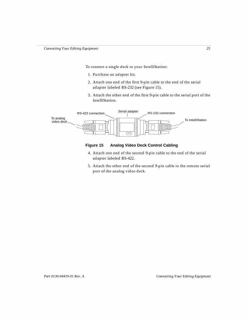
To connect a single deck to your IntelliStation:
1. Purchase an adapter kit.
2. Attach one end of the first 9-pin cable to the end of the serial adapter labeled RS-232 (see Figure 15).
3. Attach the other end of the first 9-pin cable to the serial port of the IntelliStation.
Figure 15 Analog Video Deck Control Cabling
4. Attach one end of the second 9-pin cable to the end of the serial adapter labeled RS-422.
5. Attach the other end of the second 9-pin cable to the remote serial port of the analog video deck.
To IntelliStation
Serial adapter RS-232 connectionRS-422 connection
To analogvideo deck
26 Connecting Your Editing Equipment
Connecting Your Editing Equipment Part 0130-04419-01 Rev. A
Copyright and DisclaimerProduct specifications are subject to change without notice and do not represent a commitment on the part of Avid Technology, Inc. The software described in this document is furnished under a license agreement. The software may not be reverse assembled and may be used or copied only in accordance with the terms of the license agreement. It is against the law to copy the software on any medium except as specifically allowed in the license agreement. Avid products or portions thereof are protected by one or more of the following United States patents: 4,746,994; 4,970,663; 5,045,940; 5,063,448; 5,077,604; 5,245,432; 5,267,351; 5,309,528; 5,325,200; 5,355,450; 5,396,594; 5,440,348; 5,452,378; 5,467,288; 5,513,375; 5,528,310; 5,557,423; 5,568,275; 5,577,190; 5,583,496; 5,584,006; 5,627,765; 5,634,020; 5,640,601; 5,644,364; 5,654,737; 5,701,404; 5,715,018; 5,719,570; 5,724,605; 5,726,717; 5,729,673; 5,731,819; 5,745,637; 5,752,029; 5,754,180; 5,754,851; 5,781,188; 5,799,150; 5,812,216; 5,828,678; 5,842,014; 5,852,435; 5,883,670; 5,889,532; 5,892,507; 5,905,841; D352,278; D372,478; D373,778; D392,267; D392,268; D392,269; D395,291; D396,853; D398,912. Additional U.S. and foreign patents pending. No part of this document may be reproduced or transmitted in any form or by any means, electronic or mechanical, including photocopying and recording, for any purpose without the express written permission of Avid Technology, Inc.
© 2000 Avid Technology, Inc. All rights reserved. Printed in USA.
Attn. Government User(s). Restricted Rights LegendU.S. GOVERNMENT RESTRICTED RIGHTS. This Software and its documentation are “commercial computer software” or “commercial computer software documentation.” In the event that such Soft-ware or documentation is acquired by or on behalf of a unit or agency of the U.S. Government, all rights with respect to this Software and documentation are subject to the terms of the License Agreement, pursuant to FAR §12.212(a) and/or DFARS §227.7202-1(a), as applicable.
TrademarksAirPlay, AudioVision, Avid, CamCutter, Digidesign, FieldPak, Film Composer, HIIP, Image Independence, Marquee, Media Composer, Media Recorder, NewsCutter, OMF, OMF Interchange, Open Media Framework, Pro Tools, and Softimage are registered trademarks and 888 I/O, AniMatte, AudioSuite, AutoSync, AVIDdrive, AVIDdrive Towers, AvidNet, AVIDstripe, Avid Unity, Avid Xpress, AVX, DAE, D-Fi, D-FX, D-Verb, ExpertRender, FilmScribe, Intraframe, iS9, iS18, iS23, iS36, Lo-Fi, Magic Mask, Matador, MCXpress, MEDIArray, MediaDock, MediaDock Shuttle, Media Fusion, Media Illusion, MediaLog, Media Reader, MediaShare, Meridien, NaturalMatch, OMM, QuietDrive, Recti-Fi, rS9, rS18, Sci-Fi, Sound Designer II, Symphony, tools for storytellers, Vari-Fi, and Video Slave Driver are trademarks of Avid Technology, Inc., or its subsidiaries or divisions.
IBM and IntelliStation are registered trademarks of International Business Machines Corporation. RCA is a registered trademark of General Electric Company.
atools for storytellers™