considerations for iva nde instrumentation for iss … · 1 considerations for iva nde...
TRANSCRIPT
1
Considerations for IVA NDE
Instrumentation
for ISS On-Orbit NDE Applications
In-space Inspection Workshop
July 15, 2014
Contributors: Ajay Koshti, Eric Madaras, Bill Prosser, Todd Hong, George Studor, Kornel Nagy, Elizabeth
Kalla, Duane Hightower, David Stanley, and Others
Sponsors: ISS Program,
JSC Engineering and
NASA Engineering Safety Center
Presenter: Ajay Koshti, D. Sc. PE

2
Summary
• Need for ISS On-orbit NDE Equipment
• Inspection Cases
• Damage Detection Requirements
• Assessment of NDE Equipment for Use on
ISS
• Ultrasonic Testing and Eddy Current
Testing Equipment
• NDE Test Protocols
• Ultrasonic and Eddy Current Scan
Demonstration Examples
• Engineering Assessment Considerations
• Conclusions and Recommendations
IVA – Intra-Vehicular Activity, activity inside a
habitable space vehicle such as
International Space Station
Leroy Chiao Inside Destiny Space Lab
Zvezda Service Module

3
Need for On-Orbit NDE Equipment
• There is a high risk of module damage/penetration from MMOD
impact to the ISS over the life of the program.
• At present, the is a greater than 33 percent probability of ISS
penetration from MMOD over a ten year period.
• MMOD threats have been changing as more debris is being
created and additional modules are being manifested.
• Although on-orbit leak repair kits are available for pressure loss
mitigation, these kits do not address structural repair needs.
• The needed NDE tools for damage and repair assessment are not
currently available on ISS.
MMOD – Micro-Meteoroid and Orbital Debris

4
Pressure Wall on US Modules
Test Plate
Grid Outside
5
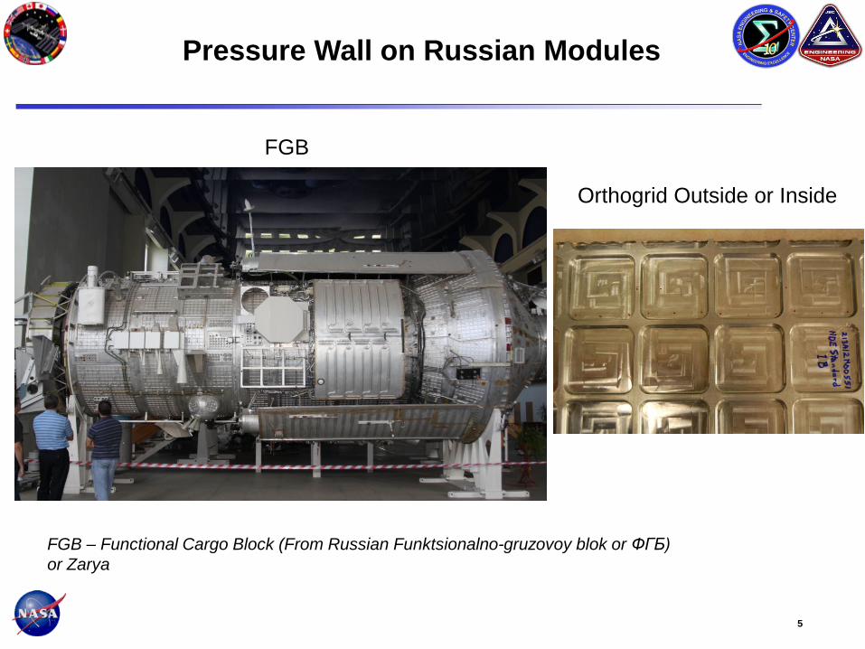
FGB
Orthogrid Outside or Inside
Pressure Wall on Russian Modules
FGB – Functional Cargo Block (From Russian Funktsionalno-gruzovoy blok or ФГБ)
or Zarya

6
Columbus Module
Location of
corner
panel
Limited
access behind
rack if not
removed
7
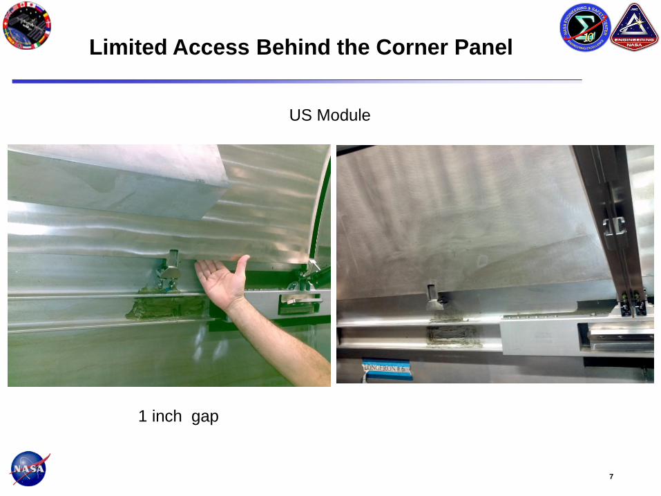
US Module
Limited Access Behind the Corner Panel
1 inch gap

8
Mitigation Step Onboard
ISS
Hardware
status Developer
New
CR
Req
1. IVA Leak Repair
Yes
USOS Cert completed
RS Cert in work US No
2a. IVA Leak location
ULD, “BAR” Set Yes Completed US, RSC E No
3. Autonomous leak detection system
UBNT Hdwe option No
On hold pending completion of
step 8 US Yes
4. NDE inspection
IVA GFE option No Planning and Draft CR in work US Yes
6. EVA Leak repair hardware
“Pressurizer” Yes
RS Cert completed
USOS Cert planning in work RSC E No
7. Permanent repair
Structural repair with bonded or welded doublers No Planning and Draft CR in work US Yes
8a. Environment characterization tests, ground
UBNT Phase I No Completed US No
8b. Environment characterization tests, ground
UBNT Phase II No
Planning in progress with
RSCE and Khrunichev US Yes
8c. Environment characterization tests, ISS on-orbit
UBNT Phase I
UBNT Phase II
Yes
No
Pending available crewtime
Planning in progress with
RSCE and Khrunichev
US Yes
Mitigation steps status for Risk 4669
“Pressurized Module Leak Detection and Repair“
Mitigation Steps for ISS Risk 4669
Requirements for NDE Inspection

9
Inspection Cases
Provide Capability for the Following Inspection Cases • Case 1: Damage to pressure wall with leak
- NDE after pressure repair (flexible patch or rigid dome)
- Ultrasonic sensor will contact pressure wall outside the repair due to inability
to sense damage through repair patch (Tape or dome)
- Shear wave scan
• Case 2: EVA Epoxy and Other Repair (future capability)
- Ultrasonic inspection of bondline, zero degree scan
• Case 3: Suspect impact damage on ISS pressure wall with no leak
- Ultrasonic zero degree scan and/or shear wave scan
• Case 4: Corrosion
- Ultrasonic zero degree scan
EVA – Extravehicular Activity such as activity outside space station

10
Inspection Case 1
Damaged area may be blocked by the leak repair patch
Flexible Patch - Single and double thickness aluminum tape
Rigid Patch - Dome-shaped aluminum plate with flexible seal
Rigid Patch Flexible Patch
11
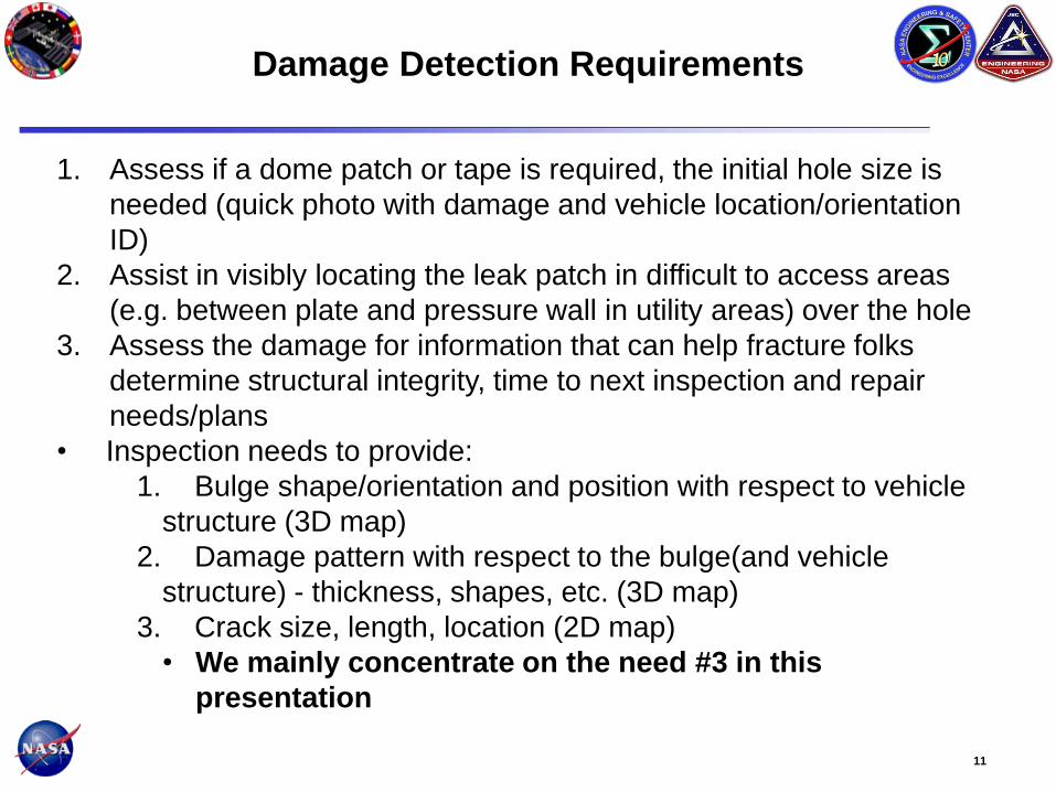
1. Assess if a dome patch or tape is required, the initial hole size is
needed (quick photo with damage and vehicle location/orientation
ID)
2. Assist in visibly locating the leak patch in difficult to access areas
(e.g. between plate and pressure wall in utility areas) over the hole
3. Assess the damage for information that can help fracture folks
determine structural integrity, time to next inspection and repair
needs/plans
• Inspection needs to provide:
1. Bulge shape/orientation and position with respect to vehicle
structure (3D map)
2. Damage pattern with respect to the bulge(and vehicle
structure) - thickness, shapes, etc. (3D map)
3. Crack size, length, location (2D map)
• We mainly concentrate on the need #3 in this
presentation
Damage Detection Requirements
12
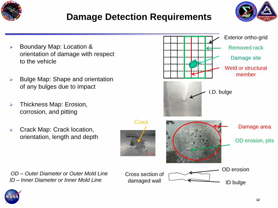
Damage Detection Requirements
Boundary Map: Location &
orientation of damage with respect
to the vehicle
Bulge Map: Shape and orientation
of any bulges due to impact
Thickness Map: Erosion,
corrosion, and pitting
Crack Map: Crack location,
orientation, length and depth
Exterior ortho-grid
Removed rack
Damage site
Weld or structural
member
I.D. bulge
Damage area
OD erosion, pits
OD erosion
ID bulge
Crack
Cross section of
damaged wall
OD – Outer Diameter or Outer Mold Line
ID – Inner Diameter or Inner Mold Line

13
Assessment of NDE Equipment for Use on ISS
The assessment focus is to recommend the optimal COTS NDE instrument for IVA
applications.
• Manufactured a range of relevant test samples
• Demonstrated/evaluated how well different instruments can detect critical flaw
types.
• Evaluated six different portable instruments.
• Three ultrasonic array systems, three eddy current systems.
• Evaluate on-orbit operational capabilities of each device.
• Evaluate potential certifiability of possible on-orbit instruments.
Photo of Astronaut
Don Pettit scanning a
curved machined
plate with artificial
flaws.
COTS – Commercial Off The Shelf

14
COTS Definition per
SSP 50835, Revision D, Appendix M
COTS is defined as commercially available hardware or software procured
directly from a vendor or authorized distributor. COTS must meet the
following criteria:
1. Is portable (is not structurally mounted). Items mounted via a Bogen Arm
are not considered structurally mounted.
2. Has no design modifications to vendor configuration
3. Has no reliability requirements
4. Will be soft stowed for launch
5. Is non-critical (2N, 2NR and 3)
6. Contains only previously certified alkaline (maximum 12 volts / 60 watts)
and/or coin cell batteries.
Assessment
• Ultrasonic Flaw Detector is considered to be “COTS”
COTS – Commercial Off The Shelf
15
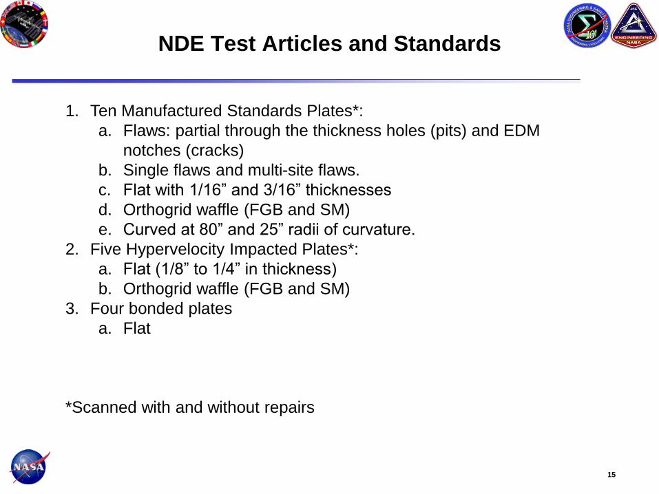
NDE Test Articles and Standards
1. Ten Manufactured Standards Plates*:
a. Flaws: partial through the thickness holes (pits) and EDM
notches (cracks)
b. Single flaws and multi-site flaws.
c. Flat with 1/16” and 3/16” thicknesses
d. Orthogrid waffle (FGB and SM)
e. Curved at 80” and 25” radii of curvature.
2. Five Hypervelocity Impacted Plates*:
a. Flat (1/8” to 1/4” in thickness)
b. Orthogrid waffle (FGB and SM)
3. Four bonded plates
a. Flat
*Scanned with and without repairs
16
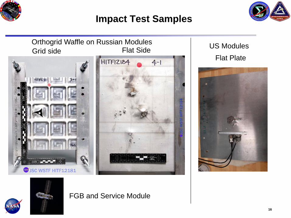
Impact Test Samples
FGB and Service Module
US Modules Orthogrid Waffle on Russian Modules
Flat Plate Grid side Flat Side

17
Test Sample With and Without Repairs
Unrepaired surface
Plate repair Tape repair

18
NDE Test Protocols
1. Ultrasonic Phased Array:
a. Angle Beam Wedge • Bends the ultrasound at an angle into the plates.
• Can penetrate along the plate under the patches.
• Simple, quick, natural way to make a two dimensional image.
• Mechanical scanner (encoder) in one direction.
• Time in the second direction.
• Used on the manufactured standard plates and impacted plates.
One Refracted Beam Path
Angle Beam Wedge
Pressure Wall
Ultrasonic Phased Array Probe
Array Sector Beams
Crack
Seal Plate
Rubber Seal

19
NDE Test Protocols
1. Ultrasonic Phased Array 0o Longitudinal Beam • Used for bondline plates
• Useful when there is no patch to deal with
• Can measure thickness of a plate.
Array
Array sector beam One reflected beam path
Zero-angle beam block
Pressure wall
20
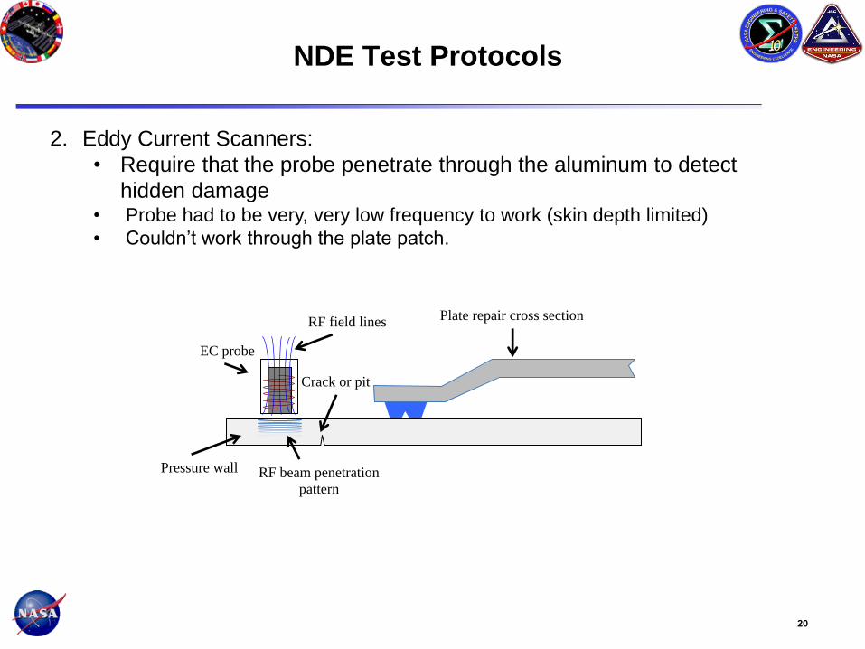
NDE Test Protocols
2. Eddy Current Scanners:
• Require that the probe penetrate through the aluminum to detect
hidden damage • Probe had to be very, very low frequency to work (skin depth limited)
• Couldn’t work through the plate patch.
EC probe
Pressure wall
Crack or pit
Plate repair cross section
RF beam penetration
pattern
RF field lines

21
Examples of Ultrasonic Scans:
Zero Degree and Shear Wave
Sonatest Veo with
5L64 Transducer All holes were detected.
Smallest and shallowest hole
C-scan Display
Standard 3
Standard 3
Translation
Direction
Beam Direction
Top Scan Display
Mosaic of
Two Scans
Scan 1
Beam
Direction
Scan 2
Beam
Direction
Ultrasonic Zero Degree Scan
Ultrasonic Shear Wave Scan
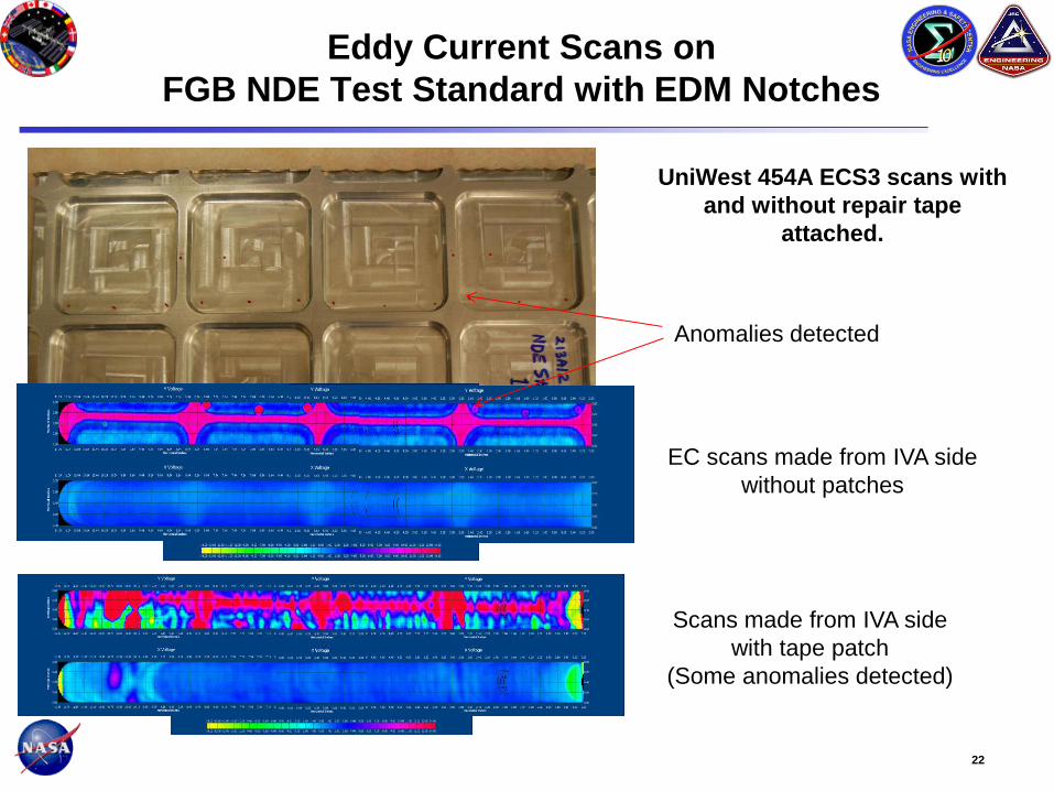
22
Eddy Current Scans on
FGB NDE Test Standard with EDM Notches
EC scans made from IVA side
without patches
Scans made from IVA side
with tape patch
(Some anomalies detected)
UniWest 454A ECS3 scans with
and without repair tape
attached.
Anomalies detected
23
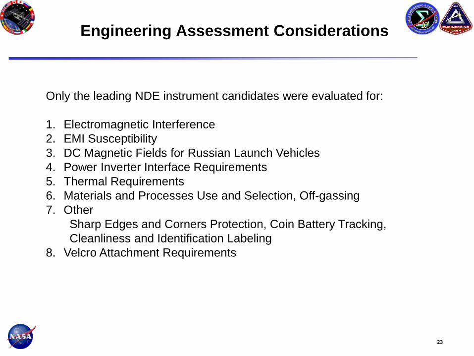
Engineering Assessment Considerations
Only the leading NDE instrument candidates were evaluated for:
1. Electromagnetic Interference
2. EMI Susceptibility
3. DC Magnetic Fields for Russian Launch Vehicles
4. Power Inverter Interface Requirements
5. Thermal Requirements
6. Materials and Processes Use and Selection, Off-gassing
7. Other
Sharp Edges and Corners Protection, Coin Battery Tracking,
Cleanliness and Identification Labeling
8. Velcro Attachment Requirements

24
Conclusions from On-Orbit COTS NDE
Equipment Assessment
1. NDE systems evaluated were sensitive to detecting structural
features such as orthogrid webs.
2. The systems evaluated were unable to detect damage directly
adjacent to the orthogrid web under a patch.
3. Ultrasonic Phased Array systems were more capable than eddy
current array/scanner systems in detecting and assessing damage
from all the manufactured test plates and simulated MMOD impacts
with the patches in place on ISS pressure wall specimens.
i. The Sonatest Veo and Olympus Omniscan MX-UT systems
performed equally, while the GE Phasor had a software
limitation.
4. The Sonatest Veo "Top-scan" saves the data from the different
inspection angles, allowing additional analysis of the results on the
ground.
25
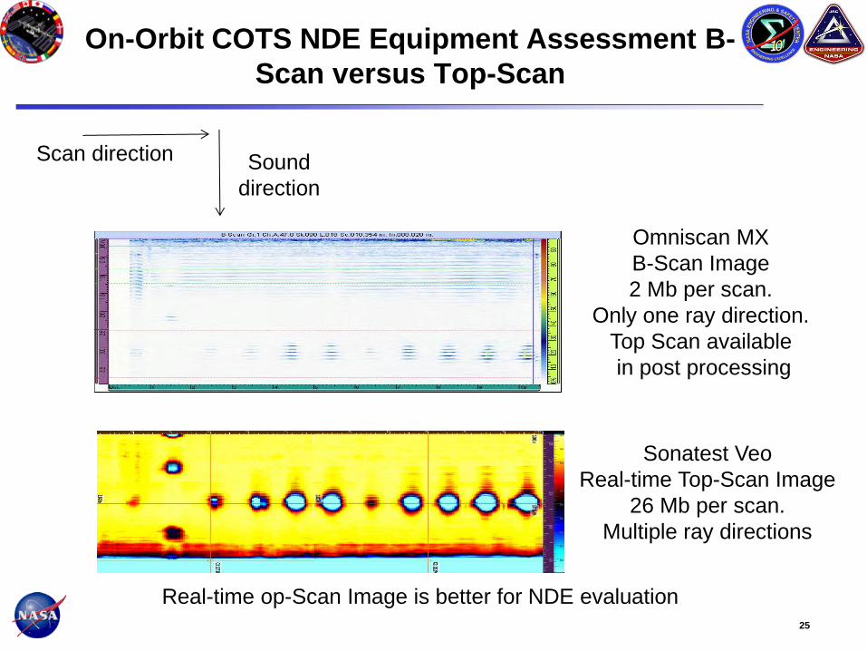
On-Orbit COTS NDE Equipment Assessment B-
Scan versus Top-Scan
Omniscan MX
B-Scan Image
2 Mb per scan.
Only one ray direction.
Top Scan available
in post processing
Sound
direction
Scan direction
Sonatest Veo
Real-time Top-Scan Image
26 Mb per scan.
Multiple ray directions
Real-time op-Scan Image is better for NDE evaluation

26
On-Orbit COTS NDE Equipment Assessment
Astronaut/Operations Testing Findings
5. ISS crew, without any additional training, were able to quickly assemble and
operate the NDE instruments evaluated using only simple one-page
procedures.
6. The need for an additional computer for image display, as required by the
UniWest 454A Eddy Current system with the ECS3 scanner was deemed
more complicated than desirable for on-orbit operations.
7. Spring-loaded position encoders used in a zero-G environment will require a
reaction force to keep the sensor in contact with the part undergoing
inspection, which will complicate operations.
8. The probes/scanning components of NDE systems evaluated are too large
(i.e. diameter and height) to permit inspections underneath racks and fixed
structure and behind panels, which limit inspection regions (i.e.
approximately 70 percent of U.S. module surface area and 30 percent of
Russian module surface area)
9. All NDE systems evaluated were deemed usable, but a preference for the
Sonatest Veo system was identified because of its simpler operating controls
and computer-human interface, and the visual display.

27
Assessment of NDE Instrumentation
for ISS-On-Orbit NDE Application
Ultrasonic Phased Array
Flaw Detectors
1. Olympus Omniscan MX UT
3. GE Phasor
2. Sonatest Veo
Eddy Current Systems
1. Olympus Omniscan MX
EC Linear Array
2. UniWest 454A with ECS3
Eddy Current Rotating Probe
Scanner
3. Jentek Sensors Grid
Station, Linear Array
Six astronauts participated in the assessment and gave
opinions on operations and suggestions for modifications • Pettit, Walker, Metcalf-Linenburger, Fincke, Yui, Aunon
• Suggestions:
• Try system out on zero-G flights.
• Didn’t like a spring loaded encoder (use an
optical encoder?).
• Want an edge guide to help with scanning.
• Like water for a couplant (easy clean up).
• Want simple procedures.
• Emulate Human Research Facility (HRF)
team’s process.
Operations criteria: 1. NDE Crew Time for measurements
2. # Crew required
3. Setup/Tear Down Time
4. NDE Expertise/Training Required by Crew
5. Preventive/Calibration/Upkeep actions
6. Access Requirements
7. ISS Interfaces
8. Size (Storage and Access impacts)
Instrument Model NDE Score
0 to 2
Ops/Astro.
Score
0 to 5
Eng. Score
0 to 5
Net Score
0 to 20
Olympus Omniscan MX
UT 1.62 3.15 3.95 11.5
Sonatest Veo 1.62 3.5 3.95 12.07
GE Phasor XS 0.98 2.7 N/A 2.65
Olympus Omniscan MX
EC 0.2 2.45 N/A 0.49
UniWest 454A ECS3 0.07 2.2 2 0.29
Jentek GridStation 0.04 N/A N/A 0 Sonatest Veo was selected by NESC Team based on the
comparative evaluation of these instruments

28
On-Orbit COTS NDE Equipment
Assessment Recommendations
The following NESC recommendations are directed to the ISS Program if a
decision is made to utilize commercial field portable NDE instrumentation
aboard the ISS to mitigate IRMA risk 4669.
1. Select the Sonatest Veo Ultrasonic Phased Array system for further
testing, modification, and eventual certification for flight

29
Objectives in Phase 1 and Later Phases
Provide capability to inspect ISS pressure wall for MMOD impact
damage before and after leak repair • Phase 1: Ultrasonic Flaw Detector for ISS
- Provide NDE capability in pressurized IVA environment to inspect areas
where direct hand access is available in U.S. and Russian modules (70% of
U.S. modules)
- Provide 2-D scanning capability on U.S. modules (not a requirement for
Russian modules due to interior ortho-grid but some coverage is be
possible)
• Later Phases - Provide IVA coverage for areas within a reach of a ~3 ft. long custom reach
tool
Custom scanner at the end of reach tool with attachment/hold-down
mechanism
Scanner should work within the 1” gap underneath U.S. module stand-
off areas and over the Russian module ortho-grid structure
Wireless encoder to improve ease of scanning operation

30
Ultrasonic Flaw Detector System Application
Requirements and Performance Characteristics
Ultrasonic Flaw Detector Application Requirements
• Capable of performing ultrasonic zero degree and shear wave scans on flat or slightly
contoured (radius > 25’) ISS aluminum pressure shell wall to provide evaluation of
suspect MMOD damage and repair of the same. Ultrasonic Flaw Detector is not meant for
detecting leak due to MMOD damage.
• Provide NDE capability in pressurized IVA environment to inspect areas where direct hand
access is available in U.S. (estimated 70% area) and Russian modules
• Capable of producing 2D scans on approximately 8” x 8” areas in presence or absence of a
dome or tape patch repair.
• See “inspection cases” and “damage detection requirements” for more details - Verify written procedures by scanning NDE Standard 3 and 5 on ground and on ISS (DTO)
Veo Performance Characteristics • USB port on Veo and USB memory stick for data storage and file transfer
- Verify on qualification unit
• Other instrument performance characteristics per Veo (16:128) specifications
- See “Veo specification” by Sonatest Inc.
- Ethernet and VGA ports are available on Veo but are not planned to be used.
- Verify on qualification unit
31
Physical Interface Requirements
• Restrained on-orbit by a Nylon hook-and-loop fastening system, “Velcro”™ • Use Velcro on Veo, NDE standards, transducer cables, encoder cables, soft cases etc.
• USB memory stick is used for data storage and file transfer
• Interface to the power inverter in USOS providing 110 VAC output for Ultrasonic Flaw Detector. Battery is not used to power the instrument.
• An ultrasonic transducer would contact the inspection surface. Potable water (approx. 1 teaspoon) is used as a couplant. Use water from crew drinking water bag. Water is preferred by crew over gel type medical ultrasound couplant Aquasonic 100 which is available on the ISS.
• An encoder (wheel) would contact the inspected surface during scanning.
• A 300mm steel ruler would be taped to the surface to act as a guide for scanning and to provide scale in photographs of the inspected area.
• A crew member would hold the transducer/encoder assembly in one or two hands and scan the part surface. A second crew member may be needed to operate the Veo instrument and assist the first crew member as needed. One crew member may be sufficient for the ISS demonstration of ultrasonic scanning on test pieces but if used in actual inspection of the pressure wall, two crew members would likely be needed.
32
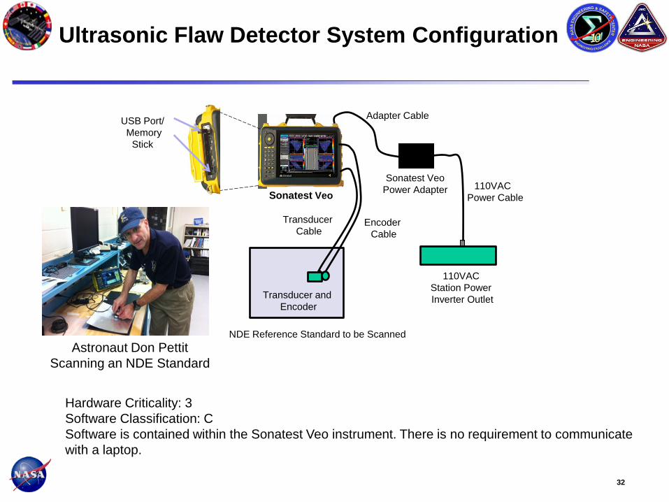
Ultrasonic Flaw Detector System Configuration
Sonatest Veo
Power Adapter
Adapter Cable
110VAC
Power Cable
110VAC
Station Power
Inverter Outlet Transducer and
Encoder
USB Port/
Memory
Stick
Sonatest Veo
NDE Reference Standard to be Scanned
Transducer
Cable Encoder
Cable
Hardware Criticality: 3
Software Classification: C
Software is contained within the Sonatest Veo instrument. There is no requirement to communicate
with a laptop.
Astronaut Don Pettit
Scanning an NDE Standard

33
Damaged Plate, Shear Wave Scan Paths and
Template
Scan A 1, A2, A11
Scan B3, B4
Scan C5, C6
Scan D7,D8
Scan E9, E10
Rib
Location
Transducer Path (Typical)
Ultrasonic Beam
Direction
(Typical)
34
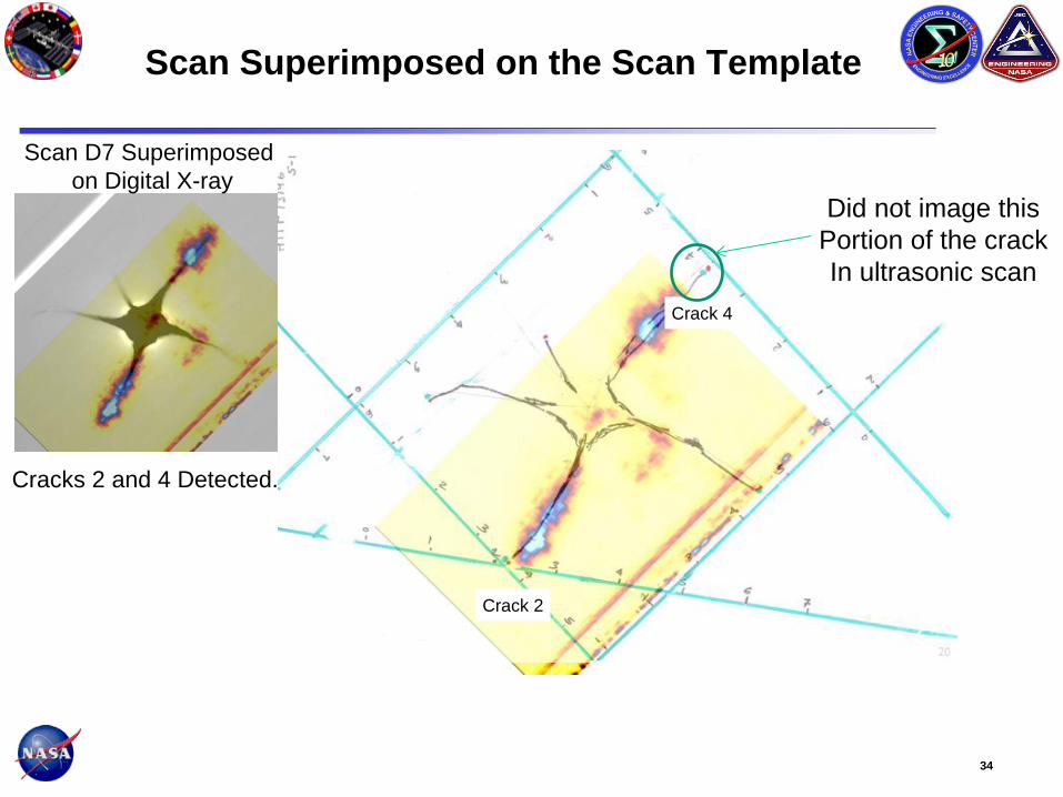
Scan Superimposed on the Scan Template
Cracks 2 and 4 Detected.
Crack 4
Crack 2
Did not image this
Portion of the crack
In ultrasonic scan
Scan D7 Superimposed
on Digital X-ray
35
Example of C-scan Image Comparison With
Damage Photo
The photo image matches with the superimposed scan image approximately. Ultrasonic scan shows
considerable variation in the signal response from the cracks. Crack orientation, depth and other
damage in the path of ultrasonic beam influences the ultrasonic signal amplitude from cracks. Overall
damage area given by the ultrasonic scan matches (+0.0, -0.4”) with the visually observed dark soot
region.
Mirror Image of
Impact Side Photo
Superimposed Scans
Dark region

36
Conclusions and Recommendations
• Ultrasonic and eddy current Scanning are viable for
IVA NDE applications however many improvements
are necessary
• Array eddy current systems need to become
compact
• Wireless or non-contact encoder would be
desirable so that the astronaut does not have to
move the encoder with transducer.
• Access under the ISS racks or corner panels is
very limited. Need NDE device on a stick.
• Software to mosaic, merge and superimpose NDE
scans s and images is needed.
NDE Reach Tool
(Shown:
Uniwest/Boeing/US Air
force Surgical NDE
Tool)
Mosaic, Merge, and
Superimpose
Scans and Images
(Shown: Manually
Superimposed
Composite Image)
Wireless Tracking or
Encoder Sensor
(Shown IR Sensor)
Wireless Tracking
or Encoder (Shown
Visible Light
Camera Tracking)

37
1. Eliminate wheeled encoder. Implement "wireless" or optical/infrared encoders
2. Lower profile transducers and scanners that can be attached to reach devices
3. Scan superimpose, mosaic and merge software.
4. Software/new camera sensors that can create a 3D map from simple
camera/borescope "pictures" of the damage.
5. Visible inspection in difficult to access areas - reach tools, more control for
existing videoscopes, tiny rovers, 3D - see where to position patch with the tool.
6. Monitoring inspection devices and procedures after initial damage inspection.
• Post inspection monitoring for damage change detection - e.g. Metis
sensors installed to trigger inspections
7. Penetrating imagers - see damage through a metal barrier - Aluminum tape
patch, aluminum dome patch or through the thicker plate that is near the
pressure wall along the utility runs
8. Making it possible for the astronaut to operate equipment with both hands and
not float away - temporary adhesion for feet/knees.
9. Glue-less temporary adhesion for sensors
List of Enhancements Needed for IVA and EVA
Inspections